Embed Size (px)
Citation preview

Maintenance Manual MM-96173
Q+TM LX500 andMX500 Cam Brakes
Issued 06-07

Service Notes
Service NotesThis maintenance manual describes the correct service and repair procedures for Meritor Q+TM LX500 and MX500 cam brakes. The information contained in this manual was current at time of printing and is subject to change without notice or liability.
You must follow your company procedures when you service or repair equipment or components. You must understand all procedures and instructions before you begin to work on a unit. Some procedures require the use of special tools for safe and correct service. Failure to use special tools when required can cause serious personal injury to service personnel, as well as damage to equipment and components.
Meritor uses the following notations to warn the user of possible safety problems and to provide information that will prevent damage to equipment and components.
A WARNING indicates a procedure that you must follow exactly to avoid seriouspersonal injury.
A CAUTION indicates a procedure that you must follow exactly to avoid damaging equipment or components. Serious personal injury can also occur.
NOTE: A NOTE indicates an operation, procedure or instruction that is important for proper service. A NOTE can also supply information that will help to make service quicker and easier.
This symbol indicates that fasteners mustbe tightened to a specific torque.
How to Obtain Additional Maintenance, Service and Product InformationVisit Literature on Demand at meritor.com to access and order additional information.
Contact the Meritor OnTrac™ Customer Call Center at 866-668-7221 (United States and Canada); 001-800-889-1834 (Mexico); or email [email protected].
WARNING
CAUTION

Table of Contents
Asbestos and Non-Asbestos Fibers Warnings . . . . . . . . . . . . . . . . . . . . . . . . . . . . . . . . . 1
Exploded Views . . . . . . . . . . . . . . . . . . . . . . . . . . . . . . . . . . . . . . . . . . . . . . . . . . . . . . . . . . . . . 2
Section 1: Introduction Q+TM LX500 Cam Brake Package with the Extended Lube Feature . . . . . . . . . . . . . . . . . . . . . . . . 4Q+TM MX500 Cam Brake with the Extended Maintenance Package Option Available for On-Highway Linehaul Applications Only Identifying Q+TM LX500 and MX500 Brakes Q+TM LX500 Cam Brakes Q+TM MX500 Cam Brakes . . . . . . . . . . . . . . . . . . . . . . . . . . . . . . . . . . . . . . . . . . . . . . . . . . . . 5Comparing 15-Inch Q+TM LX500 and MX500 Brakes with the 15-Inch Q Series Brake Q+TM LX500 and MX500 Features Specifications
Section 2: Disassembly Remove Wheel Components . . . . . . . . . . . . . . . . . . . . . . . . . . . . . . . . . . . . . . . . . . . . . . . . . . . 6Remove Brake Shoes . . . . . . . . . . . . . . . . . . . . . . . . . . . . . . . . . . . . . . . . . . . . . . . . . . . . . . . . 7Remove Camshaft and Slack Adjuster
Section 3: Prepare Parts for Assembly Cleaning Parts . . . . . . . . . . . . . . . . . . . . . . . . . . . . . . . . . . . . . . . . . . . . . . . . . . . . . . . . . . . . 8Dry Parts After Cleaning Corrosion Protection Inspect Parts Slack Adjusters . . . . . . . . . . . . . . . . . . . . . . . . . . . . . . . . . . . . . . . . . . . . . . . . . . . . . . . . . . . . 9Drums
Section 4: Assembly Install Camshaft, Seals and Bushings . . . . . . . . . . . . . . . . . . . . . . . . . . . . . . . . . . . . . . . . . . . . 10For Brake Assemblies with Cast Spiders . . . . . . . . . . . . . . . . . . . . . . . . . . . . . . . . . . . . . . . . . 11For Brake Assemblies with Stamped Spiders Install Brake Shoes . . . . . . . . . . . . . . . . . . . . . . . . . . . . . . . . . . . . . . . . . . . . . . . . . . . . . . . . 12Before Specified Time or Mileage Lubrication Intervals After Specified Time or Mileage Lubrication Intervals Q+TM LX500 and MX500 Specifications Lining Wear Sensor . . . . . . . . . . . . . . . . . . . . . . . . . . . . . . . . . . . . . . . . . . . . . . . . . . . . . . . . 14Installing Meritor’s Automatic Slack AdjusterHanded and Unhanded Slack Adjusters Pull Pawls . . . . . . . . . . . . . . . . . . . . . . . . . . . . . . . . . . . . . . . . . . . . . . . . . . . . . . . . . . . . . . 15Installation Procedure Checking Brake Chamber Push Rod Stroke and Adjusting the Clevis Position . . . . . . . . . . . . . . . . 16Brake Slack Adjuster Position (BSAP) Method Meritor’s Automatic Slack Adjuster Template . . . . . . . . . . . . . . . . . . . . . . . . . . . . . . . . . . . . . . 17Adjust the Brake . . . . . . . . . . . . . . . . . . . . . . . . . . . . . . . . . . . . . . . . . . . . . . . . . . . . . . . . . . 18
Section 5: Reline the Brakes Reline the Brakes . . . . . . . . . . . . . . . . . . . . . . . . . . . . . . . . . . . . . . . . . . . . . . . . . . . . . . . . . 19

Table of Contents
Section 6: LubricationLubrication Intervals for Q+TM LX500 and MX500 Cam Brakes with
Automatic Slack Adjusters . . . . . . . . . . . . . . . . . . . . . . . . . . . . . . . . . . . . . . . . . . . . . . . 20Do Not Lubricate the LX500 and MX500 Brakes and Automatic Slack Adjusters
Before Specified Time or Mileage Intervals Lubricating the Q+TM LX500 and MX500 Cam Brakes and Automatic Slack
Adjusters After Specified Time or Mileage Intervals
Section 7: Diagnostics . . . . . . . . . . . . . . . . . . . . . . . . . . . . . . . . . . . . . . . . . . . . . . . . . . . . . 22
Section 8: Recommended Periodic Service Recommended Periodic Service . . . . . . . . . . . . . . . . . . . . . . . . . . . . . . . . . . . . . . . . . . . . . . . 23
Section 9: Inspection Brake Inspections Before the Recommended Lubrication Interval . . . . . . . . . . . . . . . . . . . . . . . . 24Brake Inspections After the Recommended Lubrication Interval Visual Inspection . . . . . . . . . . . . . . . . . . . . . . . . . . . . . . . . . . . . . . . . . . . . . . . . . . . . . . . . . 25Federal Roadside Inspection Brake In-Service Adjustment Inspection Truck or Tractor . . . . . . . . . . . . . . . . . . . . . . . . . . . . . . . . . . . . . . . . . . . . . . . . . . . . . . . . . 26
Section 10: Torque Table . . . . . . . . . . . . . . . . . . . . . . . . . . . . . . . . . . . . . . . . . . . . . . . . . . . 27

Asbestos and Non-Asbestos Fibers
ASBESTOS FIBERS WARNING The following procedures for servicing brakes are recommended to reduce exposure to asbestos fiber dust, a cancer and lung disease hazard. Material Safety Data Sheets are available from Meritor.
Hazard SummaryBecause some brake linings contain asbestos, workers who service brakes must understand the potential hazards of asbestos and precautions for reducing risks. Exposure to airborne asbestos dust can cause serious and possibly fatal diseases, including asbestosis (a chronic lung disease) and cancer, principally lung cancer and mesothelioma (a cancer of the lining of the chest or abdominal cavities). Some studies show that the risk of lung cancer among persons who smoke and who are exposed to asbestos is much greater than the risk for non-smokers. Symptoms of these diseases may not become apparent for 15, 20 or more years after the first exposure to asbestos.Accordingly, workers must use caution to avoid creating and breathing dust when servicing brakes. Specific recommended work practices for reducing exposure to asbestos dust follow. Consult your employer for more details.
Recommended Work Practices1. Separate Work Areas. Whenever feasible, service brakes in a separate area away from other operations to reduce risks to unprotected persons. OSHA has set a maximum allowable level of exposure for asbestos of 0.1 f/cc as an 8-hour time-weighted average and 1.0 f/cc averaged over a 30-minute period. Scientists disagree, however, to what extent adherence to the maximum allowable exposure levels will eliminate the risk of disease that can result from inhaling asbestos dust. OSHA requires that the following sign be posted at the entrance to areas where exposures exceed either of the maximum allowable levels:
DANGER: ASBESTOSCANCER AND LUNG DISEASE HAZARD
AUTHORIZED PERSONNEL ONLYRESPIRATORS AND PROTECTIVE CLOTHING
ARE REQUIRED IN THIS AREA. 2. Respiratory Protection. Wear a respirator equipped with a high-efficiency (HEPA) filter approved by NIOSH or MSHA for use with asbestos at all times when servicing brakes, beginning with the removal of the wheels.3. Procedures for Servicing Brakes.a. Enclose the brake assembly within a negative pressure enclosure. The enclosure
should be equipped with a HEPA vacuum and worker arm sleeves. With the enclosure in place, use the HEPA vacuum to loosen and vacuum residue from the brake parts.
b. As an alternative procedure, use a catch basin with water and a biodegradable, non-phosphate, water-based detergent to wash the brake drum or rotor and other brake parts. The solution should be applied with low pressure to prevent dust from becoming airborne. Allow the solution to flow between the brake drum and the brake support or the brake rotor and caliper. The wheel hub and brake assembly components should be thoroughly wetted to suppress dust before the brake shoes or brake pads are removed. Wipe the brake parts clean with a cloth.
c. If an enclosed vacuum system or brake washing equipment is not available, employers may adopt their own written procedures for servicing brakes, provided that the exposure levels associated with the employer’s procedures do not exceed the levels associated with the enclosed vacuum system or brake washing equipment. Consult OSHA regulations for more details.
d. Wear a respirator equipped with a HEPA filter approved by NIOSH or MSHA for use with asbestos when grinding or machining brake linings. In addition, do such work in an area with a local exhaust ventilation system equipped with a HEPA filter.
e. NEVER use compressed air by itself, dry brushing, or a vacuum not equipped with a HEPA filter when cleaning brake parts or assemblies. NEVER use carcinogenic solvents, flammable solvents, or solvents that can damage brake components as wetting agents.
4. Cleaning Work Areas. Clean work areas with a vacuum equipped with a HEPA filter or by wet wiping. NEVER use compressed air or dry sweeping to clean work areas. When you empty vacuum cleaners and handle used rags, wear a respirator equipped with a HEPA filter approved by NIOSH or MSHA for use with asbestos. When you replace a HEPA filter, wet the filter with a fine mist of water and dispose of the used filter with care.5. Worker Clean-Up. After servicing brakes, wash your hands before you eat, drink or smoke. Shower after work. Do not wear work clothes home. Use a vacuum equipped with a HEPA filter to vacuum work clothes after they are worn. Launder them separately. Do not shake or use compressed air to remove dust from work clothes.6. Waste Disposal. Dispose of discarded linings, used rags, cloths and HEPA filters with care, such as in sealed plastic bags. Consult applicable EPA, state and local regulations on waste disposal.
Regulatory GuidanceReferences to OSHA, NIOSH, MSHA, and EPA, which are regulatory agencies in the United States, are made to provide further guidance to employers and workers employed within the United States. Employers and workers employed outside of the United States should consult the regulations that apply to them for further guidance.
NON-ASBESTOS FIBERS WARNING The following procedures for servicing brakes are recommended to reduce exposure to non-asbestos fiber dust, a cancer and lung disease hazard. Material Safety Data Sheets are available from Meritor.
Hazard SummaryMost recently manufactured brake linings do not contain asbestos fibers. These brake linings may contain one or more of a variety of ingredients, including glass fibers, mineral wool, aramid fibers, ceramic fibers and silica that can present health risks if inhaled. Scientists disagree on the extent of the risks from exposure to these substances. Nonetheless, exposure to silica dust can cause silicosis, a non-cancerous lung disease. Silicosis gradually reduces lung capacity and efficiency and can result in serious breathing difficulty. Some scientists believe other types of non-asbestos fibers, when inhaled, can cause similar diseases of the lung. In addition, silica dust and ceramic fiber dust are known to the State of California to cause lung cancer. U.S. and international agencies have also determined that dust from mineral wool, ceramic fibers and silica are potential causes of cancer.Accordingly, workers must use caution to avoid creating and breathing dust when servicing brakes. Specific recommended work practices for reducing exposure to non-asbestos dust follow. Consult your employer for more details.
Recommended Work Practices1. Separate Work Areas. Whenever feasible, service brakes in a separate area away from other operations to reduce risks to unprotected persons. 2. Respiratory Protection. OSHA has set a maximum allowable level of exposure for silica of 0.1 mg/m3 as an 8-hour time-weighted average. Some manufacturers of non-asbestos brake linings recommend that exposures to other ingredients found in non-asbestos brake linings be kept below 1.0 f/cc as an 8-hour time-weighted average. Scientists disagree, however, to what extent adherence to these maximum allowable exposure levels will eliminate the risk of disease that can result from inhaling non-asbestos dust.Therefore, wear respiratory protection at all times during brake servicing, beginning with the removal of the wheels. Wear a respirator equipped with a high-efficiency (HEPA) filter approved by NIOSH or MSHA, if the exposure levels may exceed OSHA or manufacturers’ recommended maximum levels. Even when exposures are expected to be within the maximum allowable levels, wearing such a respirator at all times during brake servicing will help minimize exposure.3. Procedures for Servicing Brakes.a. Enclose the brake assembly within a negative pressure enclosure. The enclosure
should be equipped with a HEPA vacuum and worker arm sleeves. With the enclosure in place, use the HEPA vacuum to loosen and vacuum residue from the brake parts.
b. As an alternative procedure, use a catch basin with water and a biodegradable, non-phosphate, water-based detergent to wash the brake drum or rotor and other brake parts. The solution should be applied with low pressure to prevent dust from becoming airborne. Allow the solution to flow between the brake drum and the brake support or the brake rotor and caliper. The wheel hub and brake assembly components should be thoroughly wetted to suppress dust before the brake shoes or brake pads are removed. Wipe the brake parts clean with a cloth.
c. If an enclosed vacuum system or brake washing equipment is not available, carefully clean the brake parts in the open air. Wet the parts with a solution applied with a pump-spray bottle that creates a fine mist. Use a solution containing water, and, if available, a biodegradable, non-phosphate, water-based detergent. The wheel hub and brake assembly components should be thoroughly wetted to suppress dust before the brake shoes or brake pads are removed. Wipe the brake parts clean with a cloth.
d. Wear a respirator equipped with a HEPA filter approved by NIOSH or MSHA when grinding or machining brake linings. In addition, do such work in an area with a local exhaust ventilation system equipped with a HEPA filter.
e. NEVER use compressed air by itself, dry brushing, or a vacuum not equipped with a HEPA filter when cleaning brake parts or assemblies. NEVER use carcinogenic solvents, flammable solvents, or solvents that can damage brake components as wetting agents.
4. Cleaning Work Areas. Clean work areas with a vacuum equipped with a HEPA filter or by wet wiping. NEVER use compressed air or dry sweeping to clean work areas. When you empty vacuum cleaners and handle used rags, wear a respirator equipped with a HEPA filter approved by NIOSH or MSHA, to minimize exposure. When you replace a HEPA filter, wet the filter with a fine mist of water and dispose of the used filter with care.5. Worker Clean-Up. After servicing brakes, wash your hands before you eat, drink or smoke. Shower after work. Do not wear work clothes home. Use a vacuum equipped with a HEPA filter to vacuum work clothes after they are worn. Launder them separately. Do not shake or use compressed air to remove dust from work clothes.6. Waste Disposal. Dispose of discarded linings, used rags, cloths and HEPA filters with care, such as in sealed plastic bags. Consult applicable EPA, state and local regulations on waste disposal.
Regulatory GuidanceReferences to OSHA, NIOSH, MSHA, and EPA, which are regulatory agencies in the United States, are made to provide further guidance to employers and workers employed within the United States. Employers and workers employed outside of the United States should consult the regulations that apply to them for further guidance.
1

Exploded Views
Exploded Views
1
2
3
4
56
78
12
13
9 11
10
1
1716
1824
2820
21
2519
22
23
2726
15
1611
10
14
29
15-Inch Q+TM LX500 and MX500 Cast Spider Brake
Item Description
1 Shoe and lining assembly
2 Spring — shoe retaining
3 Bushing — anchor pin
4 Anchor pin — brake shoe
5 Camshaft — LX500
6 Washer — camhead
7 Orange seal — camshaft
8 Bushing — camshaft 1.625" I.D.
9 Pin — return spring
10 Roller — brake shoe
11 Retainer — shoe roller
12 Spring — brake shoe return
13 Cast Spider — brake
14 Seal — chamber bracket
15 Bracket — camshaft & chamber
16 Capscrew — chamber bracket
17 Plug — pipe
18 Washer — camshaft (thick)
19 Slack adjuster — automatic
20 Washer — spacing
21 Snap ring — camshaft
22 Dust shield
23 Capscrew — dust shield
24 Seal — ASA
25 Orange seal — ASA
26 Bushing — camshaft 1.50" I.D.
27 Seal — camshaft
28 Washer — spacing (thin)
29 Lining Wear Sensor, If Equipped
Item Description Item Description
2

Exploded Views
Exploded Views
1
2
3
4
13
26
10
11
25
15
21
22
20
24
18
19
292317
2827
14
15
16
87
25
11
9
101
12
26
56
22
30
16.5-Inch Q+TM Drive Axle LX500 and MX500 Stamped Spider Brake
Item Description
1 Shoe and lining assembly
2 Spring — shoe retaining
3 Bushing — anchor pin
4 Anchor pin — brake shoe
5 Camshaft — “S” head
6 Washer — camhead
7 Orange seal — camshaft
8 Bushing — camshaft 1.625" I.D.
9 Pin — return spring
10 Roller — brake shoe
11 Retainer — shoe roller
12 Spring — brake shoe return
13 Stamped spider — brake
14 Bracket — camshaft & chamber
15 Capscrew — Grade 8
16 Plug — pipe
17 Washer — camshaft (thick)
18 Slack adjuster — automatic
19 Washer — spacing
20 Snap ring — camshaft
21 Dust shield
22 Capscrew — dust shield
23 Seal — ASA
24 Orange seal — ASA
25 Washer (4) — hard
26 Nut (4) — Grade 8
27 Bushing — camshaft 1.50" I.D.
28 Seal — camshaft
29 Washer — spacing (thin)
30 Lining Wear Sensor, If Equipped
Item Description Item Description
3

Section 1Introduction
Section 1IntroductionQ+TM LX500 Cam Brake Package with the Extended Lube Feature
WARNINGTo prevent serious eye injury, always wear safe eye protection when you perform vehicle maintenance or service.
NOTE: You must continue to observe all other brake preventive maintenance schedules and procedures for Q+TM LX500 and MX500 cam brakes with factory-installed Meritor automatic slack adjusters.
Meritor’s new Q+TM LX500 cam brake package includes:
� Q+TM LX500 cam brakes
� Meritor factory-installed automatic slack adjusters with threaded or welded clevises
� Extended Lube Feature: For on-highway linehaul applications, the Q+TM LX500 camshaft and slack adjusters do not require periodic lubrication for three years or 500,000 miles (805,000 km), whichever comes first. For all other vehicle applications, the lubrication interval is one year, regardless of mileage.
Q+TM MX500 Cam Brake with the Extended Maintenance Package Option
Available for On-Highway Linehaul Applications OnlyMeritor’s new Q+TM MX500 cam brake is available for on-highway linehaul applications only and includes:
� Extended Maintenance Package: Proprietary friction material on 5-inch shoes for steer axles and 8-inch shoes for drive axles for more wearable volume than LX500 Q+TM brakes.
� Extended Lube Feature: The Q+TM MX500 camshaft and slack adjusters do not require periodic lubrication for three years or 500,000 miles (805,000 km), whichever comes first.
� Meritor factory-installed automatic slack adjusters with threaded or welded clevises
Identifying Q+TM LX500 and MX500 BrakesNOTE: Do not remove the identification tag from the camshaft bracket during the extended maintenance period.
You can identify Q+TM LX500 and MX500 cam brakes by checking the identification tags affixed to the brake.
1. A brake shoe tag identifies the brake as Q+TM.
2. An additional identification tag imprinted with “SEE MERITOR MAINTENANCE MANUAL MM-96173 FOR LUBE INFO,” which is affixed to the brake chamber bracket over the top of the plugged grease hole, identifies the brake as a Q+TM LX500 or MX500 brake.
3. Q+TM LX500 and MX500 brakes and Meritor automatic slack adjusters do not have grease fittings.
Q+TM LX500 Cam BrakesThe Q+TM LX500 package consists of:
� 15-inch � 4-inch or 5-inch cam brakes on steer axle
� 16.5-inch � 7-inch or 8-inch cam brakes on drive axle
� 15-inch � 8-5/8-inch cam brakes on drive axle for 19.5-inch wheels. Figure 1.1.
Figure 1.1
16.5" Q+TM LX500 BRAKEWITH STAMPED SPIDER
4

Section 1Introduction
Q+TM MX500 Cam BrakesThe Q+TM MX500 package consists of:
� 15-inch � 5-inch cam brakes on steer axle with proprietary lining
� 16.5-inch � 8-inch cam brakes on rear drive axle with proprietary lining
� Plus LX500 components
Comparing 15-Inch Q+TM LX500 and MX500 Brakes with the 15-Inch Q Series BrakeQ+TM LX500 and MX500 15-inch cam brakes offer the following features not available on the 15-inch Q series brake.
� Double web shoe
� Cast spider
� 1.5-inch, 28-spline camshaft
� 1.75-inch offset
� 0.75-inch tapered block lining
Q+TM LX500 and MX500 Features� LX500 and MX500 seals, bushings and grease,
along with precision-machined components, keep water and contaminants out and lubrication in the assembly.
� A larger heat-treated cam head journal diameter reduces bearing stress to increase cam and bushing life.
� A new Teflon®-coated, steel-backed bushing at cam head.
� The MX500 package includes wider shoes with proprietary friction material for more wearable lining volume.
� New fiber-blended spline-end bushing improves wear resistance.
� Optional: An integrated brake spider is available on the Easy Steer PlusTM front axle.
SpecificationsNOTE: Specific applications require approval from Meritor brake engineering. For complete technical information, spec’ing assistance or original equipment manufacturer (OEM) replacement parts, contact the Meritor OnTrac™ Customer Call Center at 866-668-7221 or your Meritor representative.
Recommended GAWR* Range(lbs)
SizeDiameter � Width(inch)
Configuration
ApplicationsShoes Spiders
7-14,000 15 � 4 Fabricated Cast Steer Axle
10-14,600 15 � 5 Steer Axle
15-20,000 15 � 8-5/8 Drive Axle (19.5 Wheels)
17-23,000 16.5 � 7 Stamped Drive Axle
17-23,000 16.5 � 8 Drive Axle
* Gross Axle Weight Rating
5

Section 2Disassembly
Section 2DisassemblyRemove Wheel Components
WARNINGTo prevent serious eye injury, always wear safe eye protection when you perform vehicle maintenance or service.
Asbestos and Non-Asbestos Fibers Warning
Some brake linings contain asbestos fibers, a cancer and lung disease hazard. Some brake linings contain non-asbestos fibers, whose long-term effects to health are unknown. You must use caution when you handle both asbestos and non-asbestos materials.
WARNINGBlock the wheels to prevent the vehicle from moving. Support the vehicle with safety stands. Do not work under a vehicle supported only by jacks. Jacks can slip and fall over. Serious personal injury can result.
1. The vehicle must be on a level surface.
2. Put blocks under the wheels not being raised to keep the vehicle from moving.
3. Raise the vehicle so that the area to be serviced is off the ground. Support the vehicle with safety stands.
WARNINGWhen you work on a spring chamber, carefully follow the service instructions of the chamber manufacturer. Sudden release of a compressed spring can cause serious personal injury.
4. If the brake has spring chambers, carefully cage and lock the spring so that the spring cannot actuate during disassembly.
5. Fully release the slack adjusters so that the shoes retract and the drums clear the linings.
CAUTIONYou must disengage a pull pawl or remove a conventional pawl before rotating the manual adjusting nut, or you will damage the pawl teeth. A damaged pawl will not allow the slack adjuster to automatically adjust brake clearance. Replace damaged pawls before putting the vehicle in service.
6. Use a screwdriver or equivalent tool to disengage the pawl assembly. Figure 2.1.
Figure 2.1MANUAL
ADJUSTING NUT
DISENGAGEPAWL
7. Use a wrench to turn the manual adjusting nut until the brake shoes are fully retracted.
8. Remove the screwdriver so the pawl snaps back into engagement.
9. Use standard procedures to remove the wheels and drums from the axle.
6
Section 2Disassembly
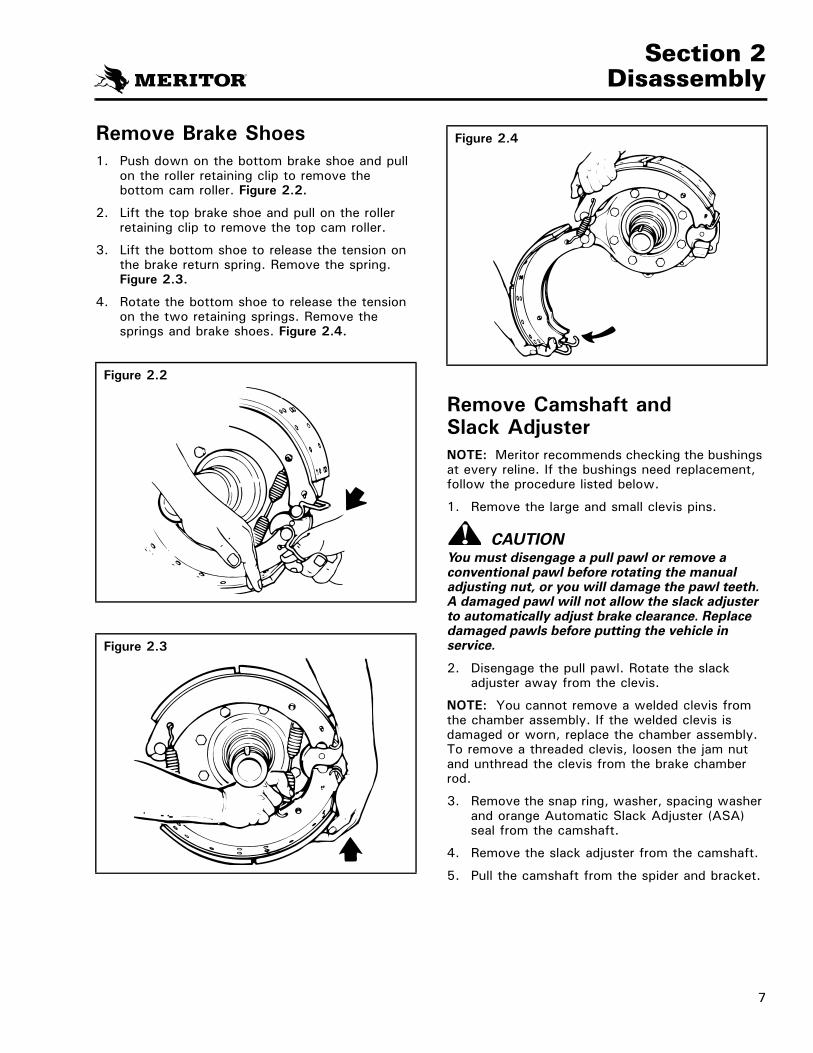
Remove Brake Shoes1. Push down on the bottom brake shoe and pull
on the roller retaining clip to remove the bottom cam roller. Figure 2.2.
2. Lift the top brake shoe and pull on the roller retaining clip to remove the top cam roller.
3. Lift the bottom shoe to release the tension on the brake return spring. Remove the spring. Figure 2.3.
4. Rotate the bottom shoe to release the tension on the two retaining springs. Remove the springs and brake shoes. Figure 2.4.
Figure 2.2
Figure 2.3
Figure 2.4
Remove Camshaft and Slack AdjusterNOTE: Meritor recommends checking the bushings at every reline. If the bushings need replacement, follow the procedure listed below.
1. Remove the large and small clevis pins.
CAUTIONYou must disengage a pull pawl or remove a conventional pawl before rotating the manual adjusting nut, or you will damage the pawl teeth. A damaged pawl will not allow the slack adjuster to automatically adjust brake clearance. Replace damaged pawls before putting the vehicle in service.
2. Disengage the pull pawl. Rotate the slack adjuster away from the clevis.
NOTE: You cannot remove a welded clevis from the chamber assembly. If the welded clevis is damaged or worn, replace the chamber assembly. To remove a threaded clevis, loosen the jam nut and unthread the clevis from the brake chamber rod.
3. Remove the snap ring, washer, spacing washer and orange Automatic Slack Adjuster (ASA) seal from the camshaft.
4. Remove the slack adjuster from the camshaft.
5. Pull the camshaft from the spider and bracket.
7

Section 3Prepare Parts for Assembly
Section 3Prepare Parts for Assembly
WARNING
To prevent serious eye injury, always wear safe eye protection when you perform vehicle maintenance or service.
Solvent cleaners can be flammable, poisonous and cause burns. Examples of solvent cleaners are carbon tetrachloride, emulsion-type cleaners and petroleum-based cleaners. To avoid serious personal injury when you use solvent cleaners, you must carefully follow the manufacturer’s product instructions and these procedures:
� Wear safe eye protection.
� Wear clothing that protects your skin.
� Work in a well-ventilated area.
� Do not use gasoline, or solvents that contain gasoline. Gasoline can explode.
� You must use hot solution tanks or alkaline solutions correctly. Follow the manufacturer’s instructions carefully.
CAUTION
Do not use hot solution tanks or water and alkaline solutions to clean ground or polished parts. Damage to parts will result.
Only use solvent cleaners on metal parts. Damage to parts will result.
Cleaning Parts
CAUTIONDo not disassemble the factory-installed automatic slack adjusters on Meritor’s Q+TM LX500 and MX500 cam brakes. Damage to components can result.
1. Use soap and water to clean non-metal parts.
2. Use soft paper or cloth that is free from dirt, oil or abrasives to dry the parts completely.
Dry Parts After CleaningDry the parts immediately after cleaning. Dry parts with clean paper or rags, or compressed air.
Corrosion ProtectionNOTE: Parts must be clean and dry before you lubricate them.
1. If you assemble parts immediately after you clean them: Lubricate parts with grease to prevent corrosion. Parts must be clean and dry before you lubricate them.
2. If you store parts after you clean them: Apply a corrosion-preventive material. Store parts in a special paper or other material that prevents corrosion.
Inspect PartsIt is important to carefully inspect all parts before assembly. Check all parts for wear or damage. Repair or replace them as required.
1. Check the spider for expanded anchor pin holes and for cracks. Replace damaged spiders and anchor pin bushings.
2. Check the camshaft bracket for broken welds, cracks and correct alignment. Replace damaged brackets.
3. Check anchor pins for corrosion and wear. Replace damaged anchor pins.
4. Check brake shoes for rust, expanded rivet holes, broken welds and correct alignment. Replace a shoe with any of the above conditions.
� On 16.5-inch brake shoes only: Anchor pin holes must not exceed 1.009-inches (25.63 mm) in diameter. The distance from the center of the anchor pin hole to the center of the roller hole must not exceed 12.779-inches (32.46 cm). Replace any shoe with measurements that do not meet specifications.
5. Check the camshaft for cracks, wear and corrosion. Check the cam head, bearing journals and splines. Replace damaged camshafts.
8

Section 3Prepare Parts for Assembly
Slack Adjusters
CAUTIONAlways replace used clevis pin retainer clips with new ones when servicing the automatic slack adjuster or chamber. Do not reuse clevis pin retainer clips after removing them. Discard used clips. When removed for maintenance or service, clevis pin retainer clips can be bent or “gapped apart” and can lose retention. Damage to components can result.
You must disengage a pull pawl or remove a conventional pawl before rotating the manual adjusting nut, or you will damage the pawl teeth. A damaged pawl will not allow the slack adjuster to automatically adjust brake clearance. Replace damaged pawls before putting the vehicle in service.
1. Check the clevis pins and the bushing in the arm of the slack adjuster. Replace the pins if they are worn. Replace the bushing if its diameter exceeds 0.531-inch (13.5 mm).
2. Check Meritor automatic slack adjusters by rotating the adjusting nut to the LEFT with an inch-pound torque wrench. Figure 3.1. Turn the gear 360 degrees (22 rotations of the adjusting nut).
� For a new slack adjuster, the torque MUST remain less than 25 lb-in (2.8 N•m) for 360 degrees.
� For an in-service slack adjuster, the torque MUST remain less than 40 lb-in (4.52 N•m) for 360 degrees.
Figure 3.1
ROTATEGEAR 360°
CAUTIONDo not disassemble the factory-installed automatic slack adjusters on Meritor’s Q+TM LX500 and MX500 cam brakes. Damage to components can result.
� If the torque value exceeds the specifications, the slack adjuster is not working correctly. Inspect and replace the slack adjuster as necessary.
DrumsNOTE: Meritor recommends that you do not turn or rebore a brake drum. Turning or reboring drums can decrease the strength and heat capacity of the drum.
1. Check the brake drums for cracks, severe heat checking, heat spotting, scoring, pitting and distortion. Replace drums as required.
2. Measure the inside diameter of the drum in several locations with a drum caliper or internal micrometer. Figure 3.2. Replace the drum if the diameter exceeds the specifications supplied by the drum manufacturer.
WARNINGDo not operate the vehicle with the brake drum worn or machined beyond the discard dimension indicated on the drum. The brake system may not operate correctly. Damage to components and serious personal injury can result.
3. Check dust shields for rust and distortion. Repair or replace damaged shields as necessary.
Figure 3.2
9

Section 4Assembly
Section 4AssemblyInstall Camshaft, Seals and Bushings
Figure 4.1
WARNINGTo prevent serious eye injury, always wear safe eye protection when you perform vehicle maintenance or service.
Asbestos and Non-Asbestos Fibers Warning
Some brake linings contain asbestos fibers, a cancer and lung disease hazard. Some brake linings contain non-asbestos fibers, whose long-term effects to health are unknown. You must use caution when you handle both asbestos and non-asbestos materials.
NOTE: To help avoid shorter lining life, Meritor recommends replacing springs, rollers, and anchor pins at each reline.
Figure 4.1
Camshaft seals closed endtoward slack adjuster.
RETAINING RING
SPACER WASHERS(0.03" [0.762 mm] MAX END PLAY)
SEAL, ORANGE
SLACK ADJUSTER
SEAL, BLACK
BUSHING,BLACK COMPOSITE
Seal lip towardslack adjuster.
Seal lip towardslack adjuster.
SPECIAL CAM HEADSEAL/WASHER FOR USEWITH STAMPED SPIDER
BRAKES ONLY
CAMSHAFT
SEAL, (ORANGE
STEEL BACKED BUSHING
SEAL
SPACER WASHER – THICK
CAST SPIDER VERSION
STAMPED SPIDER VERSION
10

Section 4Assembly
1. Check that all the spider mounting bolts are tightened to the correct torque specified inFigure 4.2.
Figure 4.2
BOLTSIZE TORQUE
7/16"-20 60-75 LB-FT 81-102 N•m1/2"-20 85-115 LB-FT 115-156 N•m9/16"-18 130-165 LB-FT 176-224 N•m5/8"-18 180-230 LB-FT 244-312 N•m
CAUTIONTo disassemble the bracket from the spider, remove the bolts. Rotate the bracket wing to loosen the bracket. Do not hit the end of the chamber bracket tube that protrudes from the spider. Damage to components can result.
2. If the camshaft bracket was removed, install the O-ring and bracket on the spider. Tighten the capscrews to the correct torque specified in the table in Section 10.
WARNINGTo prevent serious eye injury, always wear safe eye protection when you perform vehicle maintenance or service.
Prior to installing the camshaft into the brake:
3. Clean the journals with an emery cloth.
4. Lubricate the camshaft splines with Meritor specification O-695, NLGI Grade 2 lubricant.
For Brake Assemblies with Cast Spiders:� Install one seal and bushing in the spider.
� Install one seal and bushing in the chamber bracket tube. Figure 4.1.
For Brake Assemblies with Stamped Spiders:� Install both seals and bushings in the chamber
bracket tube. Figure 4.1.
1. Use a seal driver to install new camshaft bushings and seals in the spider and camshaft bracket. Figure 4.3.
Figure 4.3
CAUTIONYou must install both seals with the lips facing TOWARD the automatic slack adjuster, so that grease can purge from the slack adjuster end of the camshaft. If grease purges from the cam end, damage to components can result.
2. Install the seals with the seal lips facing TOWARD the automatic slack adjuster. Figure 4.4.
Figure 4.4
SPIDERCAMSHAFTBRACKET
SEALLIP
SEALLIP
11

Section 4Assembly
3. Install the cam head washer onto the camshaft with the bent flaps toward the spider.
4. Apply Meritor specification O-695 synthetic grease to the camshaft bushings and journals.
5. Install the camshaft through the spider and bracket so that the camshaft turns freely by hand. Figure 4.5.
Figure 4.5
Install Brake Shoes
Before Specified Time or Mileage Lubrication IntervalsWhen you install brake shoes on Q+TM LX500 and MX500 cam brakes BEFORE the specified time or mileage lubrication intervals, only grease clevis pins, anchor pins and shoe rollers. Refer to “Do Not Lubricate the LX500 and MX500 Brakes and Automatic Slack Adjusters Before Specified Time or Mileage Intervals” in Section 6 of this manual.
After Specified Time or Mileage Lubrication IntervalsWhen you install brake shoes on Q+TM LX500 and MX500 cam brakes after the specified time or mileage lubrication intervals, refer to “Lubricating the Q+TM LX500 and MX500 Cam Brakes and Automatic Slack Adjusters After Specified Time or Mileage Intervals” in Section 6 of this manual for service procedures.
Q+TM LX500 and MX500 SpecificationsThe illustrations below show specifications for 15-inch and 16.5-inch Q+TM LX500 and MX500 cam brake shoes and cams. Figure 4.6.
Figure 4.6 COMPONENTS
FMSI NO. 4707PLUS-SHAPED HOLES (+)
STAMPED IN TABLE
28 RIVET HOLESIN TABLE
NO BULGEON WEB
SHOE TAG16.5" SHOE
FMSI NO. 4702
USED WITH SPIDER
DOUBLE WEB
NO BULGEON WEB
16 RIVET HOLESIN TABLE
15" SHOE
PART NUMBERLOCATED HERE
1.18 DIA.
CAM TIP TO TIP = 4.25"
16.5" CAM (1.5" DIA.-28 SPLINES)
PART NUMBERLOCATED HERE
0.988 DIA.
CAM TIP TO TIP = 3.38"
15" CAM (1.5 DIA.-28 SPLINES)
12

Section 4Assembly
1. Put the upper brake shoe in position on the top anchor pin. Hold the lower brake shoe on the bottom anchor pin and install two new brake shoe retaining springs. Figure 4.7.
Figure 4.7
2. Rotate the lower brake shoe forward and install a new brake shoe return spring. Install the open end of the spring hooks toward the camshaft. Figure 4.8.
NOTE: Use of a spring tool may be required to assemble the new brake shoe return spring.
Figure 4.8
3. Pull each brake shoe away from the cam to permit enough space to install the cam rollers and retainers. Press the ears of the retainer together to permit the retainer to fit between the brake shoe webs. Figure 4.9.
4. Push the retainer into the brake shoe until its ears lock in the holes in the shoe webs. Figure 4.10.
Figure 4.9
WEBS
SQUEEZE
Figure 4.10
WEBHOLE
PUSH
13

Section 4Assembly
Installing Meritor’s Automatic Slack Adjuster
Handed and Unhanded Slack AdjustersThere are two different automatic slack adjuster designs: HANDED and UNHANDED. For most applications, install a HANDED automatic slack adjuster so that the pawl faces INBOARD on the vehicle.
The pawl can be on either side or on the front of the slack adjuster housing. Figure 4.11.
Pull PawlsPull pawls are spring loaded. Pry the pull pawl at least 1/32-inch to disengage the teeth. Figure 4.12. When you remove the pry bar, the “pull pawl” will re-engage automatically.
Installation ProcedureIf you are installing a new automatic slack adjuster, it must be the same type and size as the one you will replace. The table below shows slack adjuster lengths for each brake chamber size.
Chamber and Slack Adjuster Sizes
Length of Slack Adjuster (Inches)
Size of Chamber (Square Inches)
5-1/2 16, 20, 24, 30, 36
1. Install the thick large O.D. spacing washer on the camshaft.
2. Install the automatic slack adjuster seal on the camshaft in the direction shown in Figure 4.13.
3. Install the slack adjuster on the splines of the camshaft.
4. Install the orange slack adjuster seal in the direction shown in Figure 4.13.
5. Place the appropriate number of spacing washers between the slack adjuster and the snap ring to ensure less than 0.020-inch(0.51 mm) axial end play of the camshaft.
Figure 4.11
HANDED UNHANDED
Figure 4.12
PAWL
PRY UP
PULL PAWL
Figure 4.13
SEAL
ORANGESEAL
14

Section 4Assembly
CAUTIONYou must disengage a pull pawl or remove a conventional pawl before rotating the manual adjusting nut, or you will damage the pawl teeth. A damaged pawl will not allow the slack adjuster to automatically adjust brake clearance. Replace damaged pawls before putting the vehicle in service.
6. Disengage the pawl. Turn the manual adjusting nut to align the holes in the slack adjuster arm and the clevis. Figure 4.14.
CAUTIONAlways replace used clevis pin retainer clips with new ones when servicing the automatic slack adjuster or chamber. Do not reuse clevis pin retainer clips after removing them. Discard used clips. When removed for maintenance or service, clevis pin retainer clips can be bent or “gapped apart” and can lose retention. Damage to components can result.
For a Welded Clevis7. Apply anti-seize compound to the two clevis
pins. Install the clevis pins through the clevis and the slack adjuster.
8. Install the cotter pins or clevis pin retainer clips to hold the clevis pins in place. Figure 4.15.
For a Threaded Clevis� Refer to “Installing a Threaded Clevis” on
page 17.
Figure 4.14
Alignholes.
Disengagepawl.
Figure 4.15
CLEVISLARGE CLEVIS PIN
ANDRETAINER CLIP
ACTUATORROD
SMALL CLEVIS PINAND RETAINER CLIP
LARGE CLEVIS PINRETAINER CLIP
P/N 2257-D-1174
SMALL CLEVIS PINRETAINER CLIP
P/N 2257-C-1173
The clevis pin retainer clipsmust be fullyinstalled andpositioned around the side of clevis pin.
15

Section 4Assembly
Checking Brake Chamber Push Rod Stroke and Adjusting the Clevis PositionNOTE: You cannot adjust the clevis position on a chamber push rod that is equipped with a welded clevis.
There are two methods you can use to adjust the clevis position on a chamber push rod that is equipped with a threaded clevis:
� The Brake Slack Adjuster (BSAP) method.
� Meritor’s automatic slack adjuster template (for standard stroke chambers only).
Brake Slack Adjuster Position (BSAP) MethodWhen installing the automatic slack adjuster, verify that the BSAP dimension of the chamber matches the table in Figure 4.16.
Figure 4.16
NOTE: A welded clevis is long stroke only.
Standard Stroke(inch)
Long Stroke(inch)
2.75 2.25
SLACKLENGTH
5.50" (140 MM)
3.750" (95.25 MM)BRACKET OFFSET
BSAP 0.125"(3.175 MM)
+–
Meritor’s Automatic Slack Adjuster TemplateOrder the correct automatic slack adjuster template from the Meritor OnTrac™ Customer Call Center at 866-668-7221. Specify part number TP-4786 for truck or tractor drum brakes.
CAUTIONUse Meritor’s dark brown automatic slack adjuster template for truck or tractor drum brakes, part number TP-4786, to ensure that you install the automatic slack adjuster correctly. This template is not interchangeable with other Meritor slack adjuster templates. An incorrect installation can cause the automatic slack adjuster to overadjust or underadjust. Brake drag, increased stopping distances and damage to components can occur.
Measure the Automatic Slack Adjuster1. Use Meritor’s automatic slack adjuster template
part number TP-4786 to measure the length of the slack adjuster. Figure 4.17. The marks by the holes in the small end of the template indicate the length of the slack adjuster. Figure 4.18.
Figure 4.17
Color ofTemplate
PartNumber Brake Description
Dark brown
TP-4786 Truck or tractor drum brake
16

Section 4Assembly
Figure 4.18
Measure slackadjuster arm length.
CAMSHAFT CENTER
Installing a Threaded Clevis1. Install the large clevis pin through the large
holes in the template and the clevis.
2. Select the hole in the template that matches the length of the slack adjuster. Hold that hole on the center of the camshaft.
3. Look through the slot in the template. If necessary, adjust the position of the clevis until the small hole in the clevis is completely visible through the template slot. Figure 4.19.
Figure 4.19
THREADEDCLEVIS
SLOT
CAMSHAFT END
4. Check for these specifications:
� Thread engagement between the clevis and the push rod must be at least 1/2-inch (12.7 mm). Figure 4.20.
� The push rod must not extend through the clevis more than 1/8-inch (3.18 mm). If necessary, cut the push rod, or install a new push rod with a new air chamber.
Figure 4.20
MINIMUM 1/2" (12.7 MM)
MAXIMUM 1/8" (3.18 MM)
THREADED CLEVIS
5. Tighten the jam nut against the clevis to specifications in the table below.
Jam Nut Torque Specifications
Threads Torque
1/2-20 20-30 lb-ft (27-41 N•m)
5/8-18 35-50 lb-ft (48-68 N•m)
17

Section 4Assembly
Adjust the Brake
CAUTIONYou must disengage a pull pawl or remove a conventional pawl before rotating the manual adjusting nut, or you will damage the pawl teeth. A damaged pawl will not allow the slack adjuster to automatically adjust brake clearance. Replace damaged pawls before putting the vehicle in service.
1. Disengage the pawl. Turn the adjusting nut until the linings touch the drum. Turn the adjusting nut 1/2 turn in the opposite direction.
2. Measure the distance from the center of the large clevis pin to the bottom of the air chamber. Figure 4.21.
Figure 4.21Measure this distance
brakes off — brakes on.
THREADEDCLEVIS
WELDEDCLEVIS
3. Use a pry bar to move the slack adjuster so that the linings are against the drum. Measure the same distance again. The difference between this measurement and the measurement in Step 2 is the “free stroke.”
4. Turn the adjusting nut until free stroke is between 5/8–3/4-inch (15.9–19.1 mm).
5. Check the adjustment. Apply the brakes. Hold the pressure at 85 psi (586 kPa). Measure the distance from the center of the large clevis pin to the bottom of the air chamber.
6. The difference between the measurements in Step 2 and Step 5 is the adjusted chamber stroke. The adjusted stroke MUST NOT be greater than the dimensions shown in the Commercial Vehicle Safety Alliance (CVSA) North American Out-of-Service Criteria Reference Charts in Section 9.
7. Release the pawl assembly.
WARNINGWhen you work on a spring chamber, carefully follow the service instructions of the chamber manufacturer. Sudden release of a compressed spring can cause serious personal injury.
8. If the brake has spring chambers, carefully release the spring.
9. Test the vehicle to make sure that the brake system operates correctly before you put the vehicle into service.
18

Section 5Reline the Brakes
Section 5Reline the BrakesReline the Brakes
WARNINGTo prevent serious eye injury, always wear safe eye protection when you perform vehicle maintenance or service.
Asbestos and Non-Asbestos Fibers Warning
Some brake linings contain asbestos fibers, a cancer and lung disease hazard. Some brake linings contain non-asbestos fibers, whose long-term effects to health are unknown. You must use caution when you handle both asbestos and non-asbestos materials.
Vehicle brake systems require the correct lining material to perform as originally designed. The type of lining material that is specified is based on several technical considerations and DOT braking performance regulations. Always use the lining material specified by the vehicle manufacturer.
Always reline both wheels of a single axle and all four wheels of a tandem axle at the same time. Always install the same linings and drums on both wheels of a single axle and all four wheels of a tandem axle. It is not necessary for front and rear axles to have the same linings and drums.
Figure 5.1
19

Section 6Lubrication
Section 6LubricationLubrication Intervals for Q+TM LX500 and MX500 Cam Brakes with Automatic Slack Adjusters
WARNINGTo prevent serious eye injury, always wear safe eye protection when you perform vehicle maintenance or service.
The Q+TM LX500 and MX500 Cam Brake packages include factory-installed Meritor automatic slack adjusters. Q+TM LX500 and MX500 cam brakes and slack adjusters do not require lubrication for an extended period of time. (Refer to the table below.)
The camshaft hardware (seals, bushings and washers) do not require replacement for the same time period.
However, you must continue to observe all other brake preventive maintenance schedules and procedures for both Q+TM LX500 and MX500 cam brakes and Meritor automatic slack adjusters.
Lubrication Intervals
Q+TM LX500 Cam Brake
On-Highway Linehaul
3 years/500,000 miles (805,000 km)
All Other Applications
1 year, regardless of mileage
Q+TM MX500 Cam Brake
On-Highway Linehaul
3 years/500,000 miles (805,000 km)
Do Not Lubricate the LX500 and MX500 Brakes and Automatic Slack Adjusters Before Specified Time or Mileage Intervals
� Do not remove the identification tag that covers the grease plug.
� Do not grease the brake assembly or the automatic slack adjuster prior to the specified lubrication interval times or mileages in the table on this page.
Lubricating the Q+TM LX500 and MX500 Cam Brakes and Automatic Slack Adjusters After Specified Time or Mileage Intervals
1. Remove the identification tag from the chamber bracket.
2. Remove the grease plugs from both the chamber bracket and the automatic slack adjuster.
3. Install the grease fittings. Use Meritor-approved synthetic grease O-695 NLGI Grade 2 to lubricate the brake assembly through the grease fitting in the bracket until new grease flows from the inboard (slack end) seal.
4. Use Meritor-approved synthetic grease O-695 to lubricate the automatic slack adjuster through the grease fitting until new grease purges out of the pull pawl.
5. Replace the grease fittings with grease plugs. Cover the bracket plug with a new identification tag.
6. After the first lubrication, follow the manufacturer’s chassis lubrication schedule and your regular preventive maintenance schedule. You should also continue to perform periodic inspections of the brakes. (Refer to Section 9, page 24.)
20

Section 6Lubrication
Q+TM LX500 and MX500 Greasing Service Intervals and Specifications
Q+TM LX500 Cam Brake
On-Highway Linehaul
3 years/500,000 miles (805,000 km)
All Other Applications
1 year, regardless of mileage
Q+TM MX500 Cam Brake
On-Highway Linehaul
3 years/500,000 miles (805,000 km)
Approved Greases
Lubricant Recommendation
O-617-AO-617-B
Multi-Purpose Lithium Chassis Grease
O-645 Mobilgrease 28 (Military)
Mobiltemp SHC 32 (Industrial)
Aerospace Lubricants Inc. Tribolube 12-Grade 1
O-692 Amoco Super PermalubeTM #2Citgo Premium Lithium EP-2 #2Exxon Ronex MP-2 #2Kendall L-427 Super Blu #2Mobilith AW-1 #1Sohio Factran EP-2 #2
O-695 EVO-LUBE TEK-615
ComponentMeritor Specification
NLGI Grade Grease Type
OutsideTemperature
Camshaft Splines and Clevis Pins
O-695 2 Synthetic Polyurea –40°F (–40°C)
Anchor Pins
When the brake is disassembled, or when necessary, lubricate the anchor pins where they touch the brake shoes.
O-617-AorO-617-B
12
Lithium 12-Hydroxy Stearate orLithium Complex
Refer to the grease manufacturer’s specifications for the temperature service limits.
O-645 2 Synthetic Oil, Clay Base
Down to –65°F (–54°C)
O-692 1 and 2 Lithium Base Down to –40°F (–40°C)
Shoe Rollers
When the brake is disassembled, or when necessary, lubricate the rollers where they touch the brake shoes. DO NOT get grease on the part of the roller that touches the cam head.
O-617-AorO-617-B
12
Lithium 12-Hydroxy Stearate or Lithium Complex
Refer to the grease manufacturer’s specifications for the temperature service limits.
Automatic Slack Adjusters O-695 2 Synthetic Polyurea –40°F (–40°C)
Figure 6.1
21

Section 7Diagnostics
22
Section 7Diagnostics
WARNINGTo prevent serious eye injury, always wear safe eye protection when you perform vehicle maintenance or service.
Symptoms Possible Causes Corrective Actions
� Adjusted stroke is too long.
� No adjustment
� Incorrect slack adjuster part number � Check with Warehouse Distributor or Original Equipment Manufacturer.
� Clevis installed at wrong angle. � Use correct template or “BSAP” setting to install clevis correctly.
� Excessive wear between clevis and collar (more than 0.060" [1.52 mm])
� Replace with threaded clevis.
� Loose jam nut at clevis � Tighten to specification.
� Worn clevis pin bushing in slack arm (ID larger than 0.53" [13.46 mm])
� Replace bushing.
� Weak or broken return spring in air chamber (Spring force must be at least 32 lb. [142.4 N] at first push rod movement.)
� Replace return spring or air chamber.
� Spring brake does not retract fully. � Repair or replace spring brake.
� Worn or stripped teeth on pawl or actuator � Replace slack adjuster.
High torque is required to rotate worm when slack is removed from vehicle.
� In service slack, maximum worm torque: 45 lb-in (5.09 N•m)
� New or rebuilt slack, maximum worm torque: 25 lb-in (2.83 N•m)
� Replace slack adjuster.
� Excessive looseness between splines of camshaft and ASA gear
� Replace powershaft, gear or automatic slack adjuster as needed.
� Worn components (cam bushing, for example) in foundation brake
� Replace components.
� Adjusted stroke is too short.
� Linings drag.
� Non-Original Equipment Manufacturer replacement linings with excessive swell and/or growth
� Use Meritor approved linings.
� Incorrect slack adjuster part number � Check with Warehouse Distributor or Original Equipment Manufacturer.
� Clevis installed at wrong angle. � Use correct template to install clevis correctly.
� Loose jam nut at clevis � Tighten to specification.
� Spring brake does not retract fully. � Repair or replace spring brake.
� Wrong manual adjustment � Adjust brake
� Poor contact between linings and drum, or drum is out-of-round.
� Repair or replace drums or linings.
� Brake temperature imbalance � Correct brake balance.
Figure 7.1

Section 8Recommended Periodic Service
Section 8Recommended Periodic ServiceRecommended Periodic Service
WARNINGTo prevent serious eye injury, always wear safe eye protection when you perform vehicle maintenance or service.
CAUTIONDo not let brake lining wear to the point that the rivets or bolts touch the drum. Damage to the drum will occur.
Adjustment
� Adjust the brakes when the air chamber stroke exceeds the limits shown in the CVSA charts on page 26.
Lubrication
� Lubricate the brake and automatic slack adjuster according to the schedules on page 20.
Reline
� Reline the brake when lining thickness is 0.25-inch (6.3 mm) at the thinnest point.
� Replace shoe springs, check the drum and perform a major inspection.
Inspection
� Refer to Section 9 of this manual.
Complete Overhaul
� At every second reline, or as required.
A schedule for the periodic adjustment, cleaning, inspection and lubrication of the brake equipment must be made according to experience and the type of operation.
Brakes must be adjusted as frequently as required for correct operation and safety. The adjustments must give correct clearance between the lining and drum, correct pushrod travel and correct balance between the brakes.
NOTE: Correctly adjust wheel bearings before adjusting the brake.
Brakes must be cleaned, inspected and adjusted every time the wheel hubs are removed.
During a major overhaul, the following parts must be carefully checked and replaced with genuine Meritor Replacement Parts if required:
1. Spiders for distortion and loose bolts.
2. Anchor pins for wear and correct alignment.
3. Brake shoes for wear at anchor pin holes or roller slots.
4. Camshaft and camshaft bushings for wear.
5. Shoe return springs must be replaced.
6. Brake linings for grease on the lining, wear and loose rivets or bolts.
7. Drums for cracks, deep scratches or other damage.
To help ensure maximum lining life, Meritor recommends that springs, rollers, and anchor pins be replaced at each reline.
Figure 8.1
23

Section 9Inspection
Section 9InspectionBrake Inspections Before the Recommended Lubrication Interval
WARNINGTo prevent serious eye injury, always wear safe eye protection when you perform vehicle maintenance or service.
NOTE: You do not have to replace Q+TM LX500 and MX500 brake camshaft bushings and seals when you reline the brake prior to the recommended service interval.
1. Periodically inspect brake shoe linings. If the lining thickness is 0.25-inch (6.35 mm) at the thinnest point, reline the brakes. Refer to “Install Brake Shoes” in Section 4 of this manual.
2. Periodically inspect the brakes for correct clearance between the lining and drum. If you must manually adjust the brakes because of excessive air chamber stroke, correct the problem. Refer to “Adjust the Brake” in Section 4 of this manual.
Brake Inspections After the Recommended Lubrication Interval
At the first reline, inspect the cam-to-bushing radial free play and axial end play. Radial free play movement must be less than 0.020-inch (0.51 mm). Figure 9.1.
Figure 9.1
4001782a
� If radial free play movement is less than 0.020-inch (0.51 mm): Do not replace the bushings and seals.
� If radial free play movement exceeds 0.020-inch (0.51 mm): Replace the bushings and seals.
� If axial end play exceeds 0.030-inch (0.76 mm): Remove the snap ring. Add the appropriate number of spacing washers between the automatic slack adjuster and the snap ring to achieve between 0.005-inch and 0.030-inch (0.127-0.762 mm) axial free play movement.
24

Section 9Inspection
Visual Inspection
For safe operating conditions and longer component life, make these visual inspections before the vehicle is put into service:
1. Check the complete air system for worn hoses and connectors. With air pressure at 100 psi (689 kPa), brakes released and engine off, loss of tractor air pressure must not exceed two psi a minute. Total tractor and trailer loss must not exceed three psi per minute.
2. Check air compressor performance. Air system pressure must rise to approximately 100 psi (689 kPa) in two minutes.
3. The governor must be checked and set to the specifications supplied by the vehicle manufacturer.
4. The tractor or truck air system must match the specifications supplied by the vehicle manufacturer.
5. Both wheel ends of each axle must have the same linings and drums. All four wheel ends of tandem axles also must have the same linings and drums. It is not necessary for the front axle brakes to be the same as the rear driving axle brakes. Figure 9.2.
Figure 9.2
TANDEM AXLES FRONT AXLE
Both wheel ends of each axle musthave identical drums and lining.
6. Always follow the specifications supplied by the vehicle manufacturer for the correct lining to be used. Vehicle brake systems must have the correct friction material and these requirements can vary from vehicle to vehicle.
7. The return springs must retract the shoes completely when the brakes are released. Replace the return springs each time the brakes are relined. The spring brakes must retract completely when they are released.
8. Check the air chamber size and the slack adjuster length of all wheel ends. All drive axle wheel ends should have the same size air chamber and slack adjuster length. Both steer axle wheel ends should have the same size air chamber and slack adjuster length.
Federal Roadside Inspection
Brake In-Service Adjustment Inspection
NOTE: Check brake adjustment with 80-90 psi (551-620 kPa) air pressure in the brake chambers when the brakes are fully applied. 100 psi (689 kPa) in the air tanks with the engine OFF will supply 80-90 psi (551-620 kPa) in the chambers when the brakes are fully applied.
� If necessary run the engine to INCREASE the pressure to 100 psi (689 kPa).
� Turn the engine OFF. Apply and release the brakes to DECREASE the pressure to 100 psi (689 kPa).
25

Section 9Inspection
Truck or Tractor
Use the following procedures to check thein-service adjustment (adjusted chamber stroke) of truck or tractor air brakes with slack adjusters.
1. Check the gauges in the cab to make sure that the air pressure in the tanks is 100 psi (689 kPa) with the engine off and the spring chambers released.
2. With the brakes not applied, measure the distance from the bottom of the air chamber to the center of the large clevis pin on all the brakes. Figure 9.3A. Record each dimension.
3. Have another person apply and hold one full brake application. Figure 9.3B.
4. Repeat Step 2 and measure with the service brakes applied. Figure 9.3C. Record each dimension.
5. Release the brakes.
6. Calculate the adjusted chamber stroke of each brake:
a. Subtract the dimension that was measured in Step 2 from the dimension measured in Step 4.
b. The difference between the two dimensions is the adjusted chamber stroke. The adjusted chamber stroke must not be greater than the stroke length shown in the CVSA reference charts for that size and type of air chamber.
c. If the adjusted chamber stroke you measured is greater than the maximum stroke shown in the CVSA reference charts, inspect and replace the slack adjuster if necessary.
Commercial Vehicle Safety Alliance (CVSA) North American Out-of-Service Criteria Reference Charts
NOTE: A brake found at the adjustment limit is not a violation.
‘Standard Stroke’ Clamp Type Brake Chamber Data
TypeOutside Diameter(inches)
Brake Adjustment Limit (inches)
16
20
24
30
36
6-3/8
6-25/32
7-7/32
8-3/32
9
1-3/4
1-3/4
1-3/4
2
2-1/4
‘Long Stroke’ Clamp Type Brake Chamber Data
TypeOutside Diameter(inches)
Brake Adjustment Limit (inches)
16
20
24
24*
30
6-3/8
6-25/32
7-7/32
7-7/32
8-3/32
2.0
2.0
2.0
2.5
2.5
* For 3" maximum stroke type 24 chambers
Figure 9.3A Figure 9.3B Figure 9.3C
Measure Measure
• Spring brakesreleased
• Service brakesnot applied
• Spring brakesreleased
• Service brakesapplied 100 psi (689 kPa) in air
tank — engine OFF
26

Section 10Torque Table
27
Section 10Torque TableFastener Torque Table for Q+TM LX500 and MX500 Brakes
Grade 8 Nuts and Hard Flat Washers
Chamber Size 16 20 24 30 36 Spring Chamber
Bendix 30-45 lb-ft(41-61 N•m)
45-65 lb-ft(61-88 N•m)
65-85 lb-ft(88-115 N•m)
Midland 35-50 lb-ft(48-68 N•m)
70-100 lb-ft(95-136 N•m)
MGM 35-40 lb-ft(48-54 N•m)
100-115 lb-ft(136-156 N•m)
Anchorlok 110-115 lb-ft with hex nut and washer(149-203 N•m)
85-95 lb-ft with lock nut and washer(115-129 N•m)
Add camshaft spacingwashers to provide
between 0.005-0.030" (0.13-0.76 mm)
maximum end play.
BRAKE MOUNTING BOLTSGrade 8 bolts with lock nuts and two
hardened washers on each bolt.
T
CAST SPIDERTighten dust shield
mounting screws0.375-16, Grade 5 to
25-35 lb-ft(34-48 N•m)
DUST SHIELD MOUNTING (4) or (6)
STAMPED SPIDERTighten dust shield
mounting screws0.312-18, Grade 5 to
15-20 lb-ft(20-27 N•m) T
CAM BRACKET MOUNTING (4).500"-13 Thread (Cast Spider)
Grade 8 = 90-120 lb-ft (122-163 N•m)Grade 5 = 65-100 lb-ft (88-136 N•m)
.562"-12 Thread (Stamped Spider)Grade 8 = 180-190 lb-ft (243-257 N•m)
T
TPUSH ROD LOCK NUT (1).625"-18 Thread25-50 lb-ft (34-68 N•m)
.500"-20 Thread20-30 lb-ft (27-41 N•m)
T
T
AIR CHAMBER MOUNTING (2)
STAMPED SPIDERTighten chamberbracket Grade 8mounting nuts to180-19 lb-ft(244-257 N•m)
CAST SPIDERTighten chamberbracket mountingboltsGrade 5: 65-85 lb-ft(88-116 N•m)Grade 8: 90-120 lb-ft(122-163 N•m)
T
T
T
BoltSize Torque
1/2"-20 85-115 lb-ft (115-156 N•m)9/16"-18 130-165 lb-ft (176-223 N•m)5/8"-18 180-230 lb-ft (243-311 N•m)
T

Meritor Heavy Vehicle Systems, LLC2135 West Maple RoadTroy, MI 48084 USA
Information contained in this publication was in effect at the time the publication was approved for printing and is subject to change without notice or liability. Meritor Heavy Vehicle Systems, LLC, reserves the right to revise the information presented or discontinue the production of parts described at any time.
866-OnTrac1 (668-7221)meritor.com Copyright 1997 Maintenance Manual MM-96173
Meritor, Inc. Issued 06-97All Rights Reserved Printed in the USA 16579