Embed Size (px)
Citation preview
8/14/2019 Qservice ----- This Document is a Complete
http://slidepdf.com/reader/full/qservice-this-document-is-a-complete 1/100
Q s e r v i c e - - - - - T
h i s D o c u m e n t i s a c o m p l e t e s c a n f r o m t
h e O r i g i n a
l T e k t r o n i x M a n u a l - - - - -
Q s e r v i c e

8/14/2019 Qservice ----- This Document is a Complete
http://slidepdf.com/reader/full/qservice-this-document-is-a-complete 2/100
TEK070-6717-00
PRODUCT GROUP 46
First Printing October 1987
COMMITTED TO EXCELLENCE

8/14/2019 Qservice ----- This Document is a Complete
http://slidepdf.com/reader/full/qservice-this-document-is-a-complete 3/100
Copyright O 1987 Tektronix, Inc. All rights reserved. Contents
of this publication may not be reproduced in any form without
the written permission of Tektronix, Inc.
Products of Tektronix, Inc. and its subsidiaries are covered by
U.S. and foreign patents issued and pending.
Information in this publication supersedes that in all previously
published material. Specification and price change privileges re-
served. TEKTRONIX, TEK, PLOT 10, TEKTEST, SCOPE-MOBILE,
and are registered trademarks. For further information,
contact Tektronix, Inc. Corporate Offices, P.O. Box 500, Beaver-
ton, OR 97077. Phone: (503) 627-71 11; TWX: (910)467-8708;
TLX: 151754. Subsidiaries and distributors worldwide.
Printed in Hong Kong.
INSTR UM ENT SERl JMBERS
Each instrument has a serial number on a panel insert, tag, or
stamped on the chassis. The first number or letter designates
the country of manufacture. The last five digits of the serial
number are assigned sequentially and are unique to each instru-
ment. Those manufactured in the United States have six uniquedigits.
BOO0000 Tektronix, Inc., Beaverton, Oregon, U .S.A.
HK00001 Hong Kong
100000 Tektronix Guernsey, Ltd., Channel Islands
200000 Tektronix United Kingdom, Ltd., London
300000 Sony/Tektronix, Japan
700000 Tektronix Holland, NV, Heerenveen,
The Netherlands

8/14/2019 Qservice ----- This Document is a Complete
http://slidepdf.com/reader/full/qservice-this-document-is-a-complete 4/100
NOTICE to the userloperator:
The German Postal Service requires that Systems assembled by the
operatorluser of this instrument must also comply with Postal
Regulation, Vfg. 104611984, Par. 2, Sect. 1.
HlNWElS fiir den BenutzerIBetreiber:
Die vom Betreiber zusammengestellte Anlage, innerhalb derer dies
Gerat eingesetzt wird, mu0 ebenfalls den Voraussetzungen nach Par. 2,
Ziff. 1 der Vfg. 104611984 genugen.
NOTICE to the userloperator:
The German Postal Service requires that this equipment, when used ina
test setup, may only be operated if the requirements of Postal
Regulation, Vfg. 104611 984, Par. 2, Sect. 1.7.1 are complied with.
HlNWElS fur den BenutzerIBetreiber:
Dies Gerat darf in MeAaufbauten nur betrieben werden, wenn die
Voraussetzungen des Par. 2, Ziff. 1.7.1 der Vfg. 104611984 eingehalten
werden.

8/14/2019 Qservice ----- This Document is a Complete
http://slidepdf.com/reader/full/qservice-this-document-is-a-complete 5/100
Certificate of the ManufacturerIImporter
We hereby certify tha t the2205 OSCILLOSCOPE
AND ALL INSTALLED OPTIONS
complies with the RF Interference Suppression requirements ofAmtsbl.-Vfg 104611984.
The German Postal Service was notified that the equipment is beingmarketed.
The German Postal Service has the right to re-test the series and toverify that it complies.
TEKTRONIX
Bescheinigung des Herstellersllmporteurs
Hiermit wird bescheinigt, daA derldie ldas2205 OSCILLOSCOPE
AND ALL INSTALLED OPTIONS
i n ~be re ins t immun~it den Bestimmungen der Amtsblatt-Verfugung104611984 funkentstort ist.
Der Deutschen Bundespost wurde das lnverkehrbringen dieses Geratesangezeigt und die Berechtigung zur uberprufung der Serie auf Einhaltender Bestimmungen eingeraumt.
TEKTRONIX

8/14/2019 Qservice ----- This Document is a Complete
http://slidepdf.com/reader/full/qservice-this-document-is-a-complete 6/100
8/14/2019 Qservice ----- This Document is a Complete
http://slidepdf.com/reader/full/qservice-this-document-is-a-complete 7/100
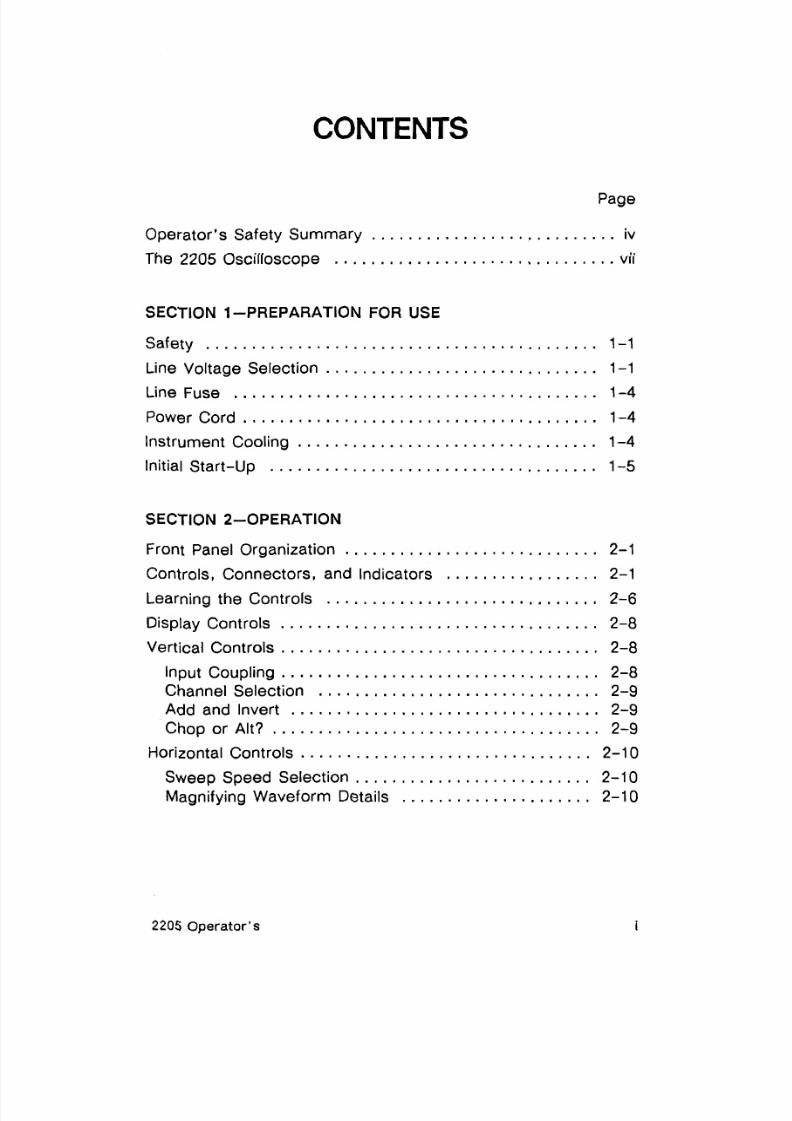
CONTENTS
Page
. . . . . . . . . . . . . . . . . . . . . . . . . . .perator's Safety Summary iv
. . . . . . . . . . . . . . . . . . . . . . . . . . . . . . .he 2205 Oscilloscope vii
SECTION 1 PREPARATION FOR USE
Safety . . . . . . . . . . . . . . . . . . . . . . . . . . . . . . . . . . . . . . . . . -1. . . . . . . . . . . . . . . . . . . . . . . . . . . . . .ine Voltage Selection 1-1
Line Fuse . . . . . . . . . . . . . . . . . . . . . . . . . . . . . . . . . . . . . . . . -4
Power Cord . . . . . . . . . . . . . . . . . . . . . . . . . . . . . . . . . . . . . . . 1-4
. . . . . . . . . . . . . . . . . . . . . . . . . . . . . . . . .nstrument Cooling 1-4
Initial Start-up . . . . . . . . . . . . . . . . . . . . . . . . . . . . . . . . . . . . 4-5
SECTION 2-OPERATION
. . . . . . . . . . . . . . . . . . . . . . . . . . . .ront Panel Organization 2-1
. . . . . . . . . . . . . . . . .ontrols. Connectors. and Indicators 2-1. . . . . . . . . . . . . . . . . . . . . . . . . . . . . .earning the Controls 2-6
. . . . . . . . . . . . . . . . . . .isplay Controls .... . .... . . . . 2-8
. . . . . . . . . . . . . . . . . . . . . . . . . . . . . . . . . . .ertical Controls 2-8
Input Coupling . . . . . . . . . . . . . . . . . . . . . . . . . . . . . . . . . . .2-8. . . . . . . . . . . . . . . . . . . . . . . . . . . . . . .hannel Selection 2-9
Add and Invert . . . . . . . . . . . . . . . . . . . . . . . . . . . . . . . . . . 2-9. . . . . . . . . . . . . . . . . . . . . . . . . . . . . . . . . . . .hop or Alt? 2-9
. . . . . . . . . . . . . . . . . . . . . . . . . . . . . . . .orizontal Controls 2-10
. . . . . . . . . . . . . . . . . . . . . . . . . .weep Speed Selection 2-10. . . . . . . . . . . . . . . . . . . . .agnifying Waveform Details 2-10
2205 Operator's

8/14/2019 Qservice ----- This Document is a Complete
http://slidepdf.com/reader/full/qservice-this-document-is-a-complete 8/100
SECTION 2-OPERATION (CONTINUED)
Trigger Controls . . . . . . . . . . . . . . . . . . . . . . . . . . . . . . . . . . 2-1 0
Which Mode to Use . . . . . . . . . . . . . . . . . . . . . . . . . . . . .Source . . . . . . . . . . . . . . . . . . . . . . . . . . . . . . . . . . . . . . . .Slope . . . . . . . . . . . . . . . . . . . . . . . . . . . . . . . . . . . . . . . . .Level . . . . . . . . . . . . . . . . . . . . . . . . . . . . . . . . . . . . . . . . .
Connecting Signals . . . . . . . . . . . . . . . . . . . . . . . . . . . . . . . .
Waveform Fidelity and Probe Grounds . . . . . . . . . . . . . .Probe Compensation . . . . . . . . . . . . . . . . . . . . . . . . . . . .Probe Handling . . . . . . . . . . . . . . . . . . . . . . . . . . . . . . . . .Coaxial Cables . . . . . . . . . . . . . . . . . . . . . . . . . . . . . . . . .
SECTION 3-APPLICATIONS
Amplitude Measurements . . . . . . . . . . . . . . . . . . . . . . . ... 3-1
Peak-to-peak Voltage . . . . . . . . . . . . . . . . . . . . . . . . . . . . 3-1
Instantaneous Voltage . . . . . . . . . . . . . . . . . . . . . . . . . . . .3-3
Algebraic Addition . . . . . . . . . . . . . . . . . . . . . . . . . . . . . . . 3-5
Common-mode Rejection . . . . . . . . . . . . . . . . . . . . . . . . . 3-6
Amplitude Comparison (Ratio) . . . . . . . . . . . . . . . . . . ... 3-7
Time Measurements. . . . . . . . . . . . . . . . . . . . . . . . . . . . . . .
3-8Time Duration . . . . . . . . . . . . . . . . . . . . . . . . . . . . . . . . . . . 3-8
Period and Frequency . . . . . . . . . . . . . . . . . . . . . . . . . . .3-1 0
Rise Time . . . . . . . . . . . . . . . . . . . . . . . . . . . . . . . . . . . . .3-1 0
Time Difference Between Pulses on
Time-Related Signals . . . . . . . . . . . . . . . . . . . . . . . . . . 3-1 2
Phase Difference . . . . . . . . . . . . . . . . . . . . . . . . . . . . . . . 3-1 4
Television Displays . . . . . . . . . . . . . . . . . . . . . . . . . ..... 3-1 7
TV Field Signals . . . . . . . . . . . . . . . . . . . . . . . . . . . . . . . .3-1 7
TV Line Signals . . . . . . . . . . . . . . . . . . . . . . . . . . . . . . . . .3-1 8
SECTION 4-CHECKS AND ADJUSTMENTS
Trace Rotation . . . . . . . . . . . . . . . . . . . . . . . . . . . . . . . . . . . . -1
Probe Compensation . . . . . . . . . . . . . . . . . . . . . . . . . . . . . . .4-1
2205 Operator's

8/14/2019 Qservice ----- This Document is a Complete
http://slidepdf.com/reader/full/qservice-this-document-is-a-complete 9/100
SEC TION 5-PERFORMANC E CHARACTE RISTICS
SEC TION 6-OPTIONS AND ACCESSO RIES
Standard Accessories . . . . . . . . . . . . . . . . . . . . . . . . . . . . . . 6-1
Options . . . . . . . . . . . . . . . . . . . . . . . . . . . . . . . . . . . . . . . . . . 6-1
Optional Accessories . . . . . . . . . . . . . . . . . . . . . . . . . . . . . . . 6-4
APPENDIX A - Magnif ied Sweep Speeds
APPENDIX B - Repackaging for Shipment
APPENDIX C - Glossary
2205 Operator's iii
8/14/2019 Qservice ----- This Document is a Complete
http://slidepdf.com/reader/full/qservice-this-document-is-a-complete 10/100
Operator's Safety Summary
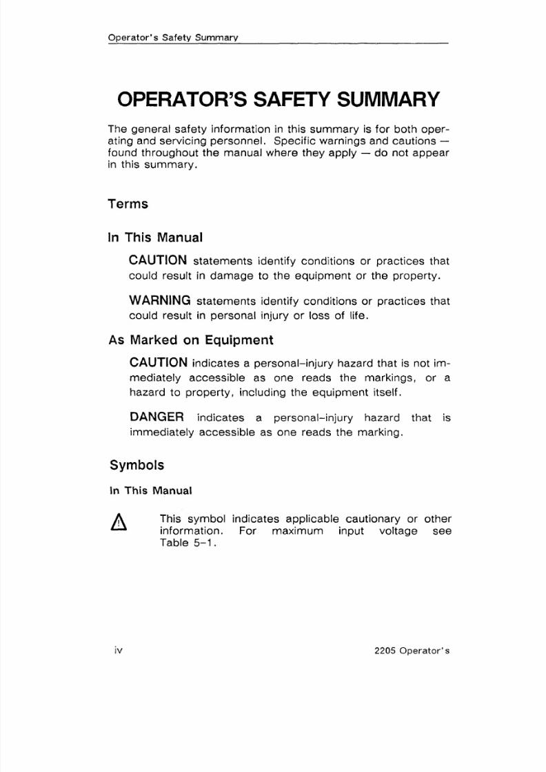
OPERATOR'S SAFETY SUMMARY
The general safety information in this summary is for both oper-ating and servicing personnel. Specific warnings and cautions -found throughout the manual where they apply - do not appear
in this summary.
Terms
In This Manual
CAUTION statements identify conditions or practices that
could result in damage to the equipment or the property.
WARNING statements identify conditions or practices that
could result in personal injury or loss of life.
As Marked on Equipment
CAUTION indicates a personal-injury hazard that is not im-
mediately accessible as one reads the markings, or a
hazard to property, including the equipment itself.
DANGER indicates a personal-injury hazard that is
immediately accessible as one reads the marking.
Symbols
In This Manual
This symbol indicates applicable cautionary or otherinformation. For maximum input voltage see
Table 5-1.
2205 Operator's

8/14/2019 Qservice ----- This Document is a Complete
http://slidepdf.com/reader/full/qservice-this-document-is-a-complete 11/100
Ooerator 's Safetv Summarv
As Marked on Equipment
DANGER-High voltage.
@ Protective ground (earth) terminal.
ATTENTION-Refer to manual.
Power Source
This product is intended to operate from a power source that
does not apply more than 250 V rms between the supply con-ductors or between either supply conductor and ground. A pro-tective ground connection, by way of the grounding conductor in
the power cord, is essential for safe operation.
Grounding the Product
This product is grounded through the grounding conductor of thepower cord. To avoid electrical shock, plug the power cord into
a properly wired receptacle before making any connections to
the product input or output terminals. A protective ground con-nection, by way of the grounding conductor in the power cord, is
essential for safe operation.
Danger Arising From Loss of Ground
Upon loss of the protective-ground connection, all accessible
conductive parts, including knobs and controls that may appearto be insulating, can render an electric shock.
Use the Proper Power Cord
Use only the power cord and connector specified for your
product.
The power cord must be in good condition.
2205 Operator 's

8/14/2019 Qservice ----- This Document is a Complete
http://slidepdf.com/reader/full/qservice-this-document-is-a-complete 12/100
Operator's Safety Summary
Read Section 1 for power-cord and connector information.
Use the Proper Fuse
To avoid fire hazard, use only a fuse of the correct type, volt-age rating and current rating as specified on the back of your
product and in Table 6-1.
Do Not Operate in an Explosive A tmosp here
To avoid explosion, do not operate this product in an explosive
atmosphere.
Do Not Remove Covers or Panels
To avoid personal injury, do not remove the product covers orpanels. Do not operate the product without the covers andpanels properly installed.
2205 Operator's

8/14/2019 Qservice ----- This Document is a Complete
http://slidepdf.com/reader/full/qservice-this-document-is-a-complete 13/100
Operator's Safety Summary
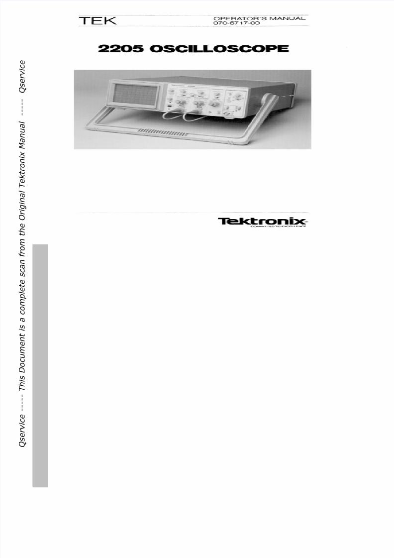
THE 2205 OSCILLOSCOPE
The TEKTRONIX 2205 Oscilloscope is a rugged, lightweight,
dual-channel, 20 MHz nstrument that features a bright, sharply
defined trace on an 80 by 100 mm cathode-ray tube (cr t) .
Its low-noise vertical system supplies calibrated deflection
factors from 5 mV to 5 V per division at full bandwidth.
Stable triggering is achieved over the full bandwidth of the verti-
cal system. The flexibility and high sensitivity of the trigger sys-
tem provides a range of conveniences such as hands-free trig-
gering with the peak-to-peak automatic mode, normal triggermode, independent selection of TV line and TV field triggering atany sweep speed, and single-sweep triggering. The trigger sig-nal is dc coupled. An external triggering signal or an externalZ-axis modulation signal can be applied via a front-panel
connector and the source-selector switches.
The horizontal system provides calibrated sweep speeds from0.5 s to 100 ns per division. For greater measurement accu-racy, a XI0 magnifier circuit extends the maximum sweep speed
to 10 ns per division.
Accessories
The instrument is shipped with the following accessories: opera-
tor's manual, two signal adapters, a power cord, and a power-
cord clamp. Part numbers for these standard accessories, as
well as for other optional accessories, are located in Section 6,Options and Accessories. The voltage-sensing signal adapterswere designed specifically to complement the performance ofyour 2205.
2205 Operator's vii

8/14/2019 Qservice ----- This Document is a Complete
http://slidepdf.com/reader/full/qservice-this-document-is-a-complete 14/100
For More Information
Should you need additional information about your 2205 Oscillo-
scope or about other Tektronix products; contact the nearestTektronix Sales Office or Distributor, consult the Tektronix prod-
uct catalog, or, in the U S , , all the Tektronix National MarketingCenter, toll free at 1-800-426-2200.
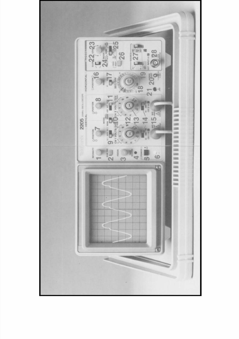
The 2205 Oscilloscope.
viii 2205 Operator's

8/14/2019 Qservice ----- This Document is a Complete
http://slidepdf.com/reader/full/qservice-this-document-is-a-complete 15/100
SECTION 1 IREPARATION
FOR USE
2205 Operator's

8/14/2019 Qservice ----- This Document is a Complete
http://slidepdf.com/reader/full/qservice-this-document-is-a-complete 16/100

8/14/2019 Qservice ----- This Document is a Complete
http://slidepdf.com/reader/full/qservice-this-document-is-a-complete 17/100
Q s e r v i c e - - - - - T h i s D o c u m e n t i s a c o m p l
e t e s c a n f r o m t
h e O r i g i n a
l T e k t r o n i x M a n u a l - - - - -
Q s e r v i c e

8/14/2019 Qservice ----- This Document is a Complete
http://slidepdf.com/reader/full/qservice-this-document-is-a-complete 18/100
Preparation for Use
Table 1-1
Power Plugs and Line Voltage Selection
LineVoltageSelector
1 5 V
PlugConfiguration
Powerlption
Std
ReferenceStandardsb
ANSl C73.11NEMA 5-15-PIEC 83UL 198.6
Plug Type
UnitedStates120 v
Europe220 v CEE (7), l, IV, VI I
IEC83IEC 127
UnitedKingdom240 V
BS 1363IEC 83IEC 127
Australia240 V
AS C112IEC 127
NorthAmerica240 V
ANSl C73.20NEMA 6-15-PIEC 83UL 198.6
Switzerland220 v
SEVIEC 127
a A 5 A, Type C fuse is installed inside the p lug of the Option A2 power co rd
b Reference Standards Abbreviations:ANSl --A merica n National Stand ards InstituteAS -Stan dards Asso ciation of AustraliaBS -British Stan dard s InstitutionCE E -International Comm ission on Rules for the Approval of Electric- quipmentIEC -International Electrote chnica l Comm issionNEM A-National Electrical Manu facturer's Asso ciationSEV -Schw eizerische r Elektrotechnischer VereinUL -Underwriters Laboratories Inc.
2205 Operator's
8/14/2019 Qservice ----- This Document is a Complete
http://slidepdf.com/reader/full/qservice-this-document-is-a-complete 19/100
Preparation for Use
PROTECTION REPLACE
O N L Y W IT H S P E C IF IE D
CAUTIONT Y P E A N D R A T E D F U S E
TO AVOID ELECTRIC
S H O C K , T H E P O W E R
CORD PROTECTION
G R O U N D IN G C O N D U C T O R
MU S T B E C O N N E C T E D
T O G R O U N D .
P O W E R
M A X W A T TS
M A X V A
D O N O T R E M O V E
COVERS. REFERS E R V IC IN G T O
[IUALIFIEO PERSONNEL.
LINE VOLTAGE
SELECTORHTEKTRONIX I N C . , BEAVERTON, OREGON, U . S . A
M A D E I N H O N G K O N G
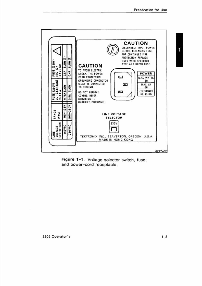
Figure f -1. Voltage selector switch, fuse,and power-cord receptacle.
2205 Operator's

8/14/2019 Qservice ----- This Document is a Complete
http://slidepdf.com/reader/full/qservice-this-document-is-a-complete 20/100
Preparation for Use
LINE FUSE
The fuse holder is located on the rear panel and contains the line
(mains) fuse. Use the following procedure to verify that theproper fuse is installed or to install a replacement fuse.
1. Unplug the power cord from the power source (if applica-
ble).
2 . Use a screwdriver to press in and slightly rotate the fuse-
holder cap counterclockwise to release it.
3. Pull the cap (with the fuse) out of the fuse holder.
4.Verify that the fuse is the same type listed on the back of theinstrument. The two type of fuses listed are not directly in-
terchangeable; they require different types of fuse caps.
5. Reinstall the fuse (or replacement fuse) in the fuse-holder
cap.
6. Replace the fuse holder and cap.
POWER CORD
This instrument has a detachable, three-wire power cord with athree-contact plug for connection to both the power source andprotective ground. The ground contact on the plug connects
through the power-cord to the external metal parts of the instru-
ment. For electrical shock protection, insert this plug only into a
power source outlet that has a properly grounded protective-
ground contact.
Instruments are shipped with the required power cord as or-
dered by the customer. Power cord plug information is pre-
sented in Table 1-1, and part numbers are listed in Table 6-1.
INSTRUMENT COOLING
Maintain adequate airflow to prevent instrument damage from
internally generated heat. Before turning on the power, check
that the spaces around the air-intake holes on the sides of the
cabinet are free of any obstruction to airflow.
2205 Operator's

8/14/2019 Qservice ----- This Document is a Complete
http://slidepdf.com/reader/full/qservice-this-document-is-a-complete 21/100
Preparation for Use
TlAL START-UP
to now, you should have made the following preparation:
Read the safety information.
Verified that the LINE VOLTAGE SELECTOR is set for thesource voltage to be used.
3. Verified the fuse.
4 . Attached the power cord.
5. Ensured adequate ventilation around the instrument.
6. Plugged the power cord into the appropriate power sourceoutlet.
Now turn on your oscilloscope by pressing in the POWER button.Observe that the Power-On indicator, located below the button,illuminates.
2205 Operator's
8/14/2019 Qservice ----- This Document is a Complete
http://slidepdf.com/reader/full/qservice-this-document-is-a-complete 22/100

8/14/2019 Qservice ----- This Document is a Complete
http://slidepdf.com/reader/full/qservice-this-document-is-a-complete 23/100
SECTION 2
OPERATION
2205 Operator's

8/14/2019 Qservice ----- This Document is a Complete
http://slidepdf.com/reader/full/qservice-this-document-is-a-complete 24/100
8/14/2019 Qservice ----- This Document is a Complete
http://slidepdf.com/reader/full/qservice-this-document-is-a-complete 25/100

8/14/2019 Qservice ----- This Document is a Complete
http://slidepdf.com/reader/full/qservice-this-document-is-a-complete 26/100
8/14/2019 Qservice ----- This Document is a Complete
http://slidepdf.com/reader/full/qservice-this-document-is-a-complete 27/100
Q s e r v i c e - - - - - T h i s D o c u m e n t i s a c o m p l
e t e s c a n f r o m t
h e O r i g i n a
l T e k t r o n i x M a n u a l - - - - -
Q s e r v i c e

8/14/2019 Qservice ----- This Document is a Complete
http://slidepdf.com/reader/full/qservice-this-document-is-a-complete 28/100
Table 2-1Summary of Controls, Connectors, and Indicators
Tit le Function Recommended Use
INTENSITY Adjusts tracebrightness.
Compensate for ambientlighting, trace speed,trigger frequency.
BEAM FIND Compresses displayto within CRT limits
Locate off-screenphenomena.
FOCUS Adjusts for finesttrace thickness.
Optimize displaydefinition.
TRACEROTATION
Adjusts traceparallel to center-line.
Compensate for earth'smagnetic field.
POWER Turns power onand off.
Control power to theinstrument.
PowerIndicator
Illuminates whenpower is turnedon.
Determine powercondition.
VERTICALPOSITION
Moves trace upor down on screen.
Position trace verticallyand compensate for dccomponent of signal.
View either channelindependently or bothchannels simultaneously.
Selects signalinputs for display.
NORM-INVERT Inverts the Channel2 signal display. Provide for differential
I H 1-CH 2) or summecCH 1 CH 2) signals
when ADD is selected.
ADD-ALT-CHOP
ADD shows alge-braic sum of CH 1and CH 2 signals.ALT displays eachchannel alternately.CHOP switches be-tween CH 1 andCH 2 signals duringthe sweep at500 kHz rate.
Display summed or indi-vidual signals.
Selects verticalsensitivity.
Adjust vertical signalto suitable size.
2205 Operator's

8/14/2019 Qservice ----- This Document is a Complete
http://slidepdf.com/reader/full/qservice-this-document-is-a-complete 29/100
Table 2-1 (cont'd)
No.
13
14
15
16
17
18
19
Title
AC-GND-DC
HORIZONTALPOSITION
MAG(X I -X1 0)
Funct ion
Provides continu-ously variable de-flection factorsbetween calibrated
ositions of thebOLTSIDIV switch.Reduces gain by a tleast 2 . 5 : l .
In AC, blocks dccomponent ofsignal. In GND,gives referencepoint and allows
Irecharging ofnput-couplingcapacitor. In DC,couples all com-ponents of signal.
Provides for inputsignal connections.CH 1 gives hori-zontal deflectionwhen SECIDIV isin X-Y; CH 2 pro-vides vertical de-flection.
POSITION movestraces horizontally.
Selects degree ofhorizontal magni-fication.
Selects time-basespeed.
Provides continu-ously variable un-calibrated sweep
speeds to at least2 .5 times the cali-brated setting.
Recommended Use
Match signals forcommon-modereadings. Adjust heightof pulse for rise-timecalculations.
Select method ofcoupling input signals tothe vertical deflectionsystem.
Apply signals to thevertical deflectionsystem.
Control trace positioningin horizontal direction.
Examine smallphenomena in detail.Extends sweep speed to10 nsldiv.
Set horizontal speedmost suited to require-ments.
Extend the slowestspeed to at least1 .25 sldiv.
2205 Operator's

8/14/2019 Qservice ----- This Document is a Complete
http://slidepdf.com/reader/full/qservice-this-document-is-a-complete 30/100

8/14/2019 Qservice ----- This Document is a Complete
http://slidepdf.com/reader/full/qservice-this-document-is-a-complete 31/100
Operation
Table 2-1 (cont'd)
No.
20
Title
PROBEADJUST
(GroundReceptacle)
SLOPE
LEVEL
TRIG'DREADY
MODE
Function
Provides approxi-mately 0.5-V ,1-kHz squarewave.
Provides safetyground and directconnection tosignal source.
Selects the slopeof the signal thattriggers the sweep
Select trigger-signal amplitudepoint.
Indicator lightswhen sweep istri gered in P-P~ 8 ~ 0 .ORM, orTV FIELD. inSingle Sweep
mode, indicatestriaaer Is armed.
P-P AUTO/TVLINE triggers fromwaveforms andtelevision lineshaving repetitionrates of at least20 Hz. NORMtriggers from ade-quate signal, withno trace in ab-sence of tri ersignal. TV+!iLDtr l ers from TV
fieW ignals; trig-get- polarity mustbe observed. SGLSWP triggerssweep only oncewhen- armed byRESET button:used for displayingor photographingnonrepetltive orunstable signals.
Recommended Use
Allows user to adjustcompensation of 1OXE obe. This source may
e used to check thebasic functioning ofvertical and horizontalcircuits but is not in-tended to check theiraccuracy.
Chassis groundconnection.
Provide ability to triggerfrom positive-going ornegative-going signals.
Select actual point oftrigger.
Indicate trigger state.
Select trigger mode.
2205 Operator's

8/14/2019 Qservice ----- This Document is a Complete
http://slidepdf.com/reader/full/qservice-this-document-is-a-complete 32/100
Operation
Table 2-1 (cont'd)
Title
RESET
SOURCE
EXT INPUT
Function
Arms tri ger cir-wit for 8GL SWP.
CH 1 , CH 2, LINE,and EXT triggersignals are selec-ted directly. InVERT MODE, trig-ger source is de-termined by theVERTICAL MODEselectors asfollows :
CH 1: trigger
comes from Chan-nel 1 signal.CH 2: triggercomes from Chan-nel 2 signal.BOTH-ADD andBOTH-CHOP:trigger is algebraicsum of Channel 1and Channel 2 sia-rials.BOTH-ALT : tria-ger comes f r o 6Channel 1 andChannel 2 onalternate sweeps.
Connectlon forapplying externalsignal for use asa trigger.
Recommended Use
Select source ofsignal that is coupledto the trigger circuit.
Trigger from a sourceother than verticalsignal. Also used forsingle-shot application
Connection forapplying externalsignal for intensitymodulation. Tointensity modulatethe dis lay, set theright TRIGGERSOURCE controlto EXT=Z.
Provide intensitymodulation fromindependent source.
2205 Operator's
8/14/2019 Qservice ----- This Document is a Complete
http://slidepdf.com/reader/full/qservice-this-document-is-a-complete 33/100
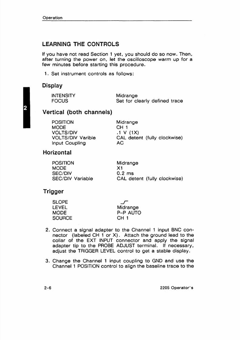
LEARNING THE CONTROLS
If you have not read Section 1 yet, you should do so now. Then,after turning the power on, let the oscilloscope warm up for a
few minutes before starting this procedure.
1. Set instrument controls as follows:
Display
INTENSITY
FOCUS
Vertical (both channels)I POSITIONMODE
VOLTSIDIVVOLTSIDIV Varible
Input Coupling
Horizontal
POSITIONMODE
SECIDIVSECIDIV Variable
Trigger
SLOPELEVEL
MODE
SOURCE
Midrange
Set for clearly defined trace
MidrangeCH 1. I v (1X)CAL detent (fully clockwise)
AC
MidrangeX1
0.2 msCAL detent (fully clockwise)
f
Midrange
P-P AUTO
CH 1
2. Connect a signal adapter to the Channel 1 input BNC con-nector (labeled CH 1 or X). Attach the ground lead to the
collar of the EXT INPUT connector and apply the signal
adapter tip to the PROBE ADJUST terminal. If necessary,
adjust the TRIGGER LEVEL control to get a stable display.
3. Change the Channel 1 input coupling to GND and use the
Channel 1 POSITION control to align the baseline trace to the
2-6 2205 Operator's
8/14/2019 Qservice ----- This Document is a Complete
http://slidepdf.com/reader/full/qservice-this-document-is-a-complete 34/100
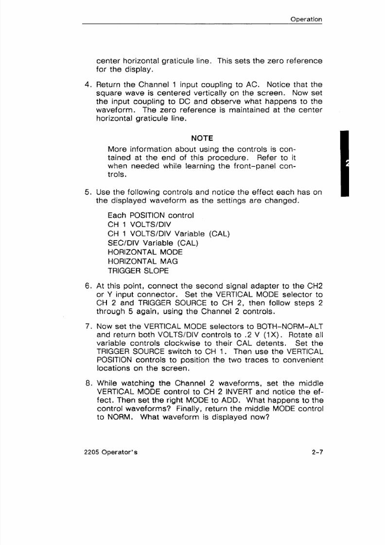
center horizontal graticule line. This sets the zero reference
for the display.
4. Return the Channel 1 input coupling to AC. Notice that the
square wave is centered vertically on the screen. Now setthe input coupling to DC and observe what happens to the
waveform. The zero reference is maintained at the center
horizontal graticule line.
NOTE
More information about using the controls is con-
tained at the end of this procedure. Refer to itwhen needed while learning the front-panel con-
t rols.
5. Use the following controls and notice the effect each has on
the displayed waveform as the settings are changed.
Each POSITION control
CH 1 VOLTSIDIV
CH 1 VOLTSIDIV Variable (CAL)
SEC/DIV Variable (CAL)
HORIZONTAL MODE
HORIZONTAL MAG
TRIGGER SLOPE
6. At this point, connect the second signal adapter to the CH2
or Y input connector. Set the VERTICAL MODE selector to
CH 2 and TRIGGER SOURCE to CH 2, then follow steps 2
through 5 again, using the Channel 2 controls.
7 . Now set the VERTICAL MODE selectors to BOTH-NORM-ALT
and return both VOLTSIDIV controls to .2 V (1X). Rotate all
variable controls clockwise to their CAL detents. Set theTRIGGER SOURCE switch to CH 1. Then use the VERTICAL
POSITION controls to position the two traces to convenient
locations on the screen.
8. While watching the Channel 2 waveforms, set the middle
VERTICAL MODE control to CH 2 INVERT and notice the ef-
fect. Then set the right MODE to ADD. What happens to the
control waveforms? Finally, return the middle MODE control
to NORM. What waveform is displayed now?
2205 Operator's
8/14/2019 Qservice ----- This Document is a Complete
http://slidepdf.com/reader/full/qservice-this-document-is-a-complete 35/100
Operation
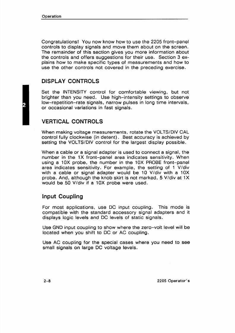
Congratulations! You now know how to use the 2205 front-panel
controls to display signals and move them about on the screen.
The remainder of this section gives you more information about
the controls and offers suggestions for their use. Section 3 ex-plains how to make specific types of measurements and how to
use the other controls not covered in the preceding exercise.
DISPLAY CONTROLS
Set the INTENSITY control for comfortable viewing, but not
brighter than you need. Use high-intensity settings to observe
low-repetition-rate signals, narrow pulses in long time intervals,
or occasional variations in fast signals.
VERTICAL CONTROLS
When making voltage measurements, rotate the VOLTSfDIV CALcontrol fully clockwise (in detent). Best accuracy is achieved by
setting the VOLTSIDIV control for the largest display possible.
When a cable or a signal adapter is used to connect a signal, thenumber in the 1X front-panel area indicates sensitivity. When
using a 10X probe, the number in the 10X PROBE front-panel
area indicates sensitivity. For example, the setting of 1 Vldivwith a cable or signal adapter would be 10 Vldiv with a 10X
probe. And, although the knob skirt is not marked, 5 Vldiv at 1X
would be 50 Vldiv if a 10X probe were used.
Input Coupling
For most applications, use DC input coupling. This mode is
compatible with the standard accessory signal adapters and itdisplays logic levels and DC levels of static signals.
Use GND input coupling to show where the zero-volt level will be
located when you shift to DC or AC coupling.
Use AC coupling for the special cases where you need to see
small signals on large DC voltage levels.
2205 Operator's
8/14/2019 Qservice ----- This Document is a Complete
http://slidepdf.com/reader/full/qservice-this-document-is-a-complete 36/100
Operation
Channel Selection
With the three VERTICAL MODE selectors, you can display com-
binations of the two vertical channels. When Channel 1 is se-
lected, the other two MODE switches are not active. When CH 2is selected, the middle MODE switch (NORMICH 2 INVERT) be-
comes active. And when BOTH channels are selected for dis-
play, all three MODE selectors are active.
ADD and INVERT
Select ADD mode to display the algebraic sum of the CHI and
CH 2 signals. When you use ADD, the CH 1 and CH 2 VOLTS/DIV settings should be equal.
Selecting CH 2 INVERT causes the polarity of the CH 2 waveform
to be inverted. This allows you to see the difference between
CH 1 and CH 2 signals on the ADD trace.
CHOP or ALT?
When BOTH channels are selected, the display is time-shared.
The CHOP mode displays each channel for a short time and mul-
tiplexes during the sweep to give the appearance of displaying
both channels at once. This mode (CHOP) works better thanALT for sweep speeds slower than 1 ms per division and for
low-repetition-rate signals that make the display flicker (up to 2psldivision) .The ALT mode displays each channel for the duration of a com-
plete sweep. It gives a cleaner display of multiple channels than
CHOP does and is usually preferred at moderate to high sweep
speeds.
Certain trigger conditions, including composite trigger selection,
can cause a display that implies a phase relationship or evensynchronization of independent waveforms. If in doubt about the
relative timing of CH 1 and CH 2 signals, experienced operators
set the TRIGGER SOURCE to either CH 1 or CH 2.
2205 Operator 's
8/14/2019 Qservice ----- This Document is a Complete
http://slidepdf.com/reader/full/qservice-this-document-is-a-complete 37/100
Operation
HORIZONTAL CONTROLS
Sweep-Speed Selection
The unmagnified sweep (MAG set to XI) is the horizontal func-
tion needed for most applications. Best measurement accuracyis achieved by setting the SECIDIV control for the fastest sweep
that will display the interval of interest. The variable control
(CAL) should be in its detent (fully clockwise).
Magnifying Waveform Details
The XI0 MAG mode expands the unmagnified trace. A magni-fied trace is useful for observing specific portions of a waveformwhen you are making accurat'e timing measurements or looking
at waveform details.
When selected, X I 0 MAG mode lets you examine details, suchas the entire leading edge of a pulse's second repetition, of a
trace up to 10 screen lengths from the trigger point.
Appendix A lists the sweep speeds for 10X magnification atevery SECIDIV control setting.
The one-division segment of the unmagnified trace centered on
the middle vertical graticule line is expanded and displayed asthe magnified trace. With the center vertical graticule line as the
reference, the investigation of waveform details around any
point on the unmagnified trace, as well as the measurement of
time with greater accuracy, become easy tasks.
TRIGGER CONTROL
For most signals, the trigger-control settings that will yield
hands-off triggering are:
MODE
SOURCE
P-P AUTO
VERT MODE
2205 Operator's

8/14/2019 Qservice ----- This Document is a Complete
http://slidepdf.com/reader/full/qservice-this-document-is-a-complete 38/100
Operation
Which Mod e to Use
P-P AUTOITV LINE-With this mode set, the range of the LEVEL
control is confined to the values between the triggering-signal
peaks. For example, selecting P-P AUTO and rotating the
LEVEL control to the center of its range establishes a trigger
point about midway between the peaks of the triggering signal.
In this mode, the absence of a triggering signal causes the
sweep to free-run. And with signals below 20 Hz, the P-P AUTO
circuit may not find the correct level.
Whenever TRIGGER SOURCE is set to VERT MODE, the trigger-
ing signal is supplied by the channel being displayed - or as
shown in Table 2-1.
The P-P AUTO mode is effective for monitoring logic signals and
television lines having at least 20 Hz repetition rate. SelectingP-P AUTO at the instrument front panel also sets the TV LINE
triggering mode.
NORM - This mode produces a sweep only when the triggering
signal meets the criteria set by the LEVEL and SLOPE controls.
With NORM mode selected, range of the LEVEL control is suffi-
cient to set any voltage threshold that can be displayed by the
instrument. In the absence of a triggering signal, no sweep
occurs.
Use the NORM mode for viewing infrequent events and erratic
signals.
SGL SWP When this mode is selected, the sweep is triggered
only once. Press the RESET button once to arm the trigger cir-
cuit and illuminate the READY indicator. When a trigger event
occurs, the sweep runs once and the READY light extinguishes.
Use the SGL SWP mode to display or photograph nonrepetitive
or unstable signals.
TV FIELD - This mode triggers the sweep at the beginning of a
television field. To change the TV field being displayed, you
must interrupt the trigger signal by setting the input coupling
switch momentarily to GND then back either DC or AC until the
desired field is displayed.
2205 Operator's
8/14/2019 Qservice ----- This Document is a Complete
http://slidepdf.com/reader/full/qservice-this-document-is-a-complete 39/100
Operation
To display Field 1 and Field 2 at the same time, connect the
same television signal to both the CH 1 and CH 2 inputs; set
VERTICAL MODE to BOTH and ALT; and set the SEC/DIV control
to 0.5 ms or faster sweep speed.
If you magnify the vertical display beyond the graticule, the trig-
ger may be degraded. To avoid trigger overload, use either CH1 or CH 2 for display and use the EXT INPUT channel with an
appropriate video signal as the trigger source. A composite
sync signal can be used for the trigger source as well as com-
posite video.
Source
Choose a single channel as the trigger source to correctly dis-play the timing relationships between two channels. Choose the
channel with the lowest frequency signal to avoid ambiguous dis-
plays.
With TRIGGER SOURCE set to VERT MODE and VERTICAL MODE
set to ADD or CHOP, the triggering signal is the algebraic sum of
the Channel 1 and Channel 2 input signals.
Use a composite trigger source only to view asynchronous
signals simultaneously. To generate a composite trigger: select
VERT MODE TRIGGER SOURCE and BOTH-ALT VERTICAL MODE.
Slope
Use the SLOPE control to select either the rising ( f ) or thefalling(1)dge of the signal to trigger the sweep.
Level
The LEVEL control gives you complete freedom to choose the
most appropriate threshold voltage on a signal to initiate sweeps
whenever any trigger mode except P-P AUTO is selected.
CONNECTING SIGNALS
The signal adapter supplied with the instrument is usually the
most convenient way to connect a signal to the 2205. These
signal adapters are shielded to prevent pickup of electromag-netic interference. When connected to the 2205 input, a signal
2-1 2 2205 Operator's
8/14/2019 Qservice ----- This Document is a Complete
http://slidepdf.com/reader/full/qservice-this-document-is-a-complete 40/100
Operation
adapter presents 1 M a and about 100 pF impedance to the cir-
cuit under test. If this capacitance is disruptive to the circuit be-
ing tested, use the optional 1OX probe.
Waveform Fidelity and Probe Grounds
When using a probe, its ground lead must be used for accurate
measurements and observations. Use the shortest ground con-nection possible for best waveform fidelity.
In some cases, a separate ground from the unit under test to the
ground receptacle on the oscilloscope front panel can reduceinterference from low-frequency hum and noise. For roughchecks of larger signals, such as 5 V logic, a ground lead sepa-rate from the probe - or even the safety ground connection,
which is shared with the unit under test - may work for a signalground. Fast signal transitions will be highly distorted, and extra-neous noise will be induced without the probe ground connec-tion, and/or with extra ground connections from the 2205 to the
circuit being tested.
Probe Compensation (Optional 1OX Probe)
Misadjustment of probe compensation is a common source ofmeasurement error. Due to variations in oscilloscope input
characteristics, probe compensation should be checked when-ever a 10X probe is moved from one oscilloscope to another orfrom one channel to another on the same oscilloscope. Always
compensate the probe to the channel on which it will be used.See the procedure in Section 4 , Checks and Adjustments.
Probe Handling (Optional 1OX Probe)
Both the probe and the probe accessories should be handledcarefully to prevent damage. Striking a hard surface can dam-
age both the probe body and the probe tip. Exercise care toprevent the cable from being crushed, kinked, or excessively
strained.
2205 Operator 's

8/14/2019 Qservice ----- This Document is a Complete
http://slidepdf.com/reader/full/qservice-this-document-is-a-complete 41/100
Coaxial Cables
To maintain good waveform fidelity and accuracy, use only high-
quality, low-loss coaxial cables. When you use 50 R or 75 flcoaxial cable, attach a matching external terminator. Some high
frequency response will be lost without external termination.
2205 Operator's

8/14/2019 Qservice ----- This Document is a Complete
http://slidepdf.com/reader/full/qservice-this-document-is-a-complete 42/100
SECTION 3
APPLICATIONS
2205 Operator's

8/14/2019 Qservice ----- This Document is a Complete
http://slidepdf.com/reader/full/qservice-this-document-is-a-complete 43/100
Q s e r v i c e - - - - - T h i s D o c u m e n t i s a c o m p l
e t e s c a n f r o m t
h e O r i g i n a
l T e k t r o n i x M a n u a l - - - - -
Q s e r v i c e

8/14/2019 Qservice ----- This Document is a Complete
http://slidepdf.com/reader/full/qservice-this-document-is-a-complete 44/100
POSITION TO
CENTERLINE
VERTICALDEFLECTION
MEASUREAMPLITUDEFROM A TO 6
6717-04
Figure 3-1. Measuring peak-to-peak voltage of a waveform.
NOTE
If the amplitude measurement is critical or i f the
trace is thick (because of hum or noise on thesignal), a more accurate result can be obtainedby measuring from the top of a peak to the top of
a valley. This will eliminate trace width from the
measurement.
8. Calculate the peak-to-peak voltage, using the following for-mula:
vertical VOLTSIDIV
Vp-P = deflection x setting
(divisions) (1OX Probe) *
* I f a I X probe is being used for the measurement, use theI X VOLTSIDIV setting.
3-2 2205 Operator's

8/14/2019 Qservice ----- This Document is a Complete
http://slidepdf.com/reader/full/qservice-this-document-is-a-complete 45/100
Applications
EXAMPLE. In Figure 3-1, the measured peak-to-peak verticaldeflection is 4 .4 divisions using a 10X attenuator probe with the
VOLTS/DIV switch set to 5V (1OX PROBE).
Substituting the given values:
Vp+ = 4.4 div x 5 V/div = 22 V.
Instantaneous Voltage
To measure the instantaneous voltage level at a given point on a
waveform, referred to ground, use the following procedure:
1. Apply the signal to either the CHI or the CH2 input connec-
tor and set the VERTICAL MODE selector to the channelused.
2. Verify that the VOLTS/DIV variable control is in the CAL
detent and set input coupling to GND.
3. Vertically position the trace to the center horizontal graticule
line. This establishes the ground reference location.
NOTE
If the measurements are to be made relative to a
voltage level other than ground, set the input cou-pling switch to DC and apply the reference voltage
to the input connector. Then position the trace tothe horizontal reference line.
4 . Set the input coupling control to DC. Points on thewaveform above the ground reference location are positive;points below are negative.
NOTE
If using Channel 2, ensure that the center VERTI-CAL MODE selector (NORM, CH 2 INVERT), is set
to NORM.
5 . If necessary, repeat Step 3 using a different horizontalground reference line that allows the waveform in Step 4 to
be displayed on screen.
2205 Opera to r 's

8/14/2019 Qservice ----- This Document is a Complete
http://slidepdf.com/reader/full/qservice-this-document-is-a-complete 46/100
Applications
6. Adjust the TRIGGER LEVEL control to obtain a stable display.
7. Set the SECIDIV control to a position that displays at least
one cycle of the signal.
8. Measure the divisions of vertical deflection between the
ground reference line and the point on the waveform at
which the level is to be determined (see Figure 3-2) .
Figure 3-2. Instantaneous voltage measurement.
9. Calculate the instantaneous voltage, using the following for-mula:
Instan- vertical polarity VOLTS/ DIV
taneous = deflection x (+ or -) x setting
Voltage (divisions) (1OX Probe) *
*If the signal adapter is being used for the measurement,use the I X VOLTSIDIV setting.
2205 Operator's

8/14/2019 Qservice ----- This Document is a Complete
http://slidepdf.com/reader/full/qservice-this-document-is-a-complete 47/100
Applications
EXAMPLE. In Figure 3-2, the zero-volt reference is as shown atthe center vertical graticule line, a 10X attenuation probe is be-
ing used, and VOLTSIDIV is set to 2 V (10X PROBE). Two un-known voltage levels, A and B, are marked on the waveform. A
is 1.5 divisions above the zero-volt reference level, and B isthree divisions below the zero-volt reference level. What are the
respective voltages of levels A and B?
Substituting the given values:
lnstantaneous Voltage A = 1.5 div x (+I x 2 Vldiv = 3.0 V.
lnstantaneous Voltage B = 3.0 div x (-1 ) x 2 Vldiv = -6.0 V.
Algebraic Addition
With the three VERTICAL MODE selectors set to BOTH-NORM-
ADD, the waveform displayed is the algebraic sum of the signalsapplied to the Channel 1 and Channel 2 inputs (CHI + CH2). If
the middle MODE selector is then set to CH2 INVERT, thewaveform displayed is the difference between the signals ap-plied to the Channel 1 and Channel 2 inputs (CHI - CH2). When
both VOLTSIDIV controls are set to the same deflection factor,
the deflection factor of the ADD trace is equal to the deflectionfactor indicated by either VOLTSIDIV control.
The following general precautions should be observed when us-ing ADD VERTICAL MODE.
1. Do not exceed the input voltage rating of the oscilloscope.
2. Do not apply signals whose peaks exceed the equivalent of
about +8 imes the VOLTSIDIV settings, because large volt-ages may distort the display. For example, with a VOLTS1
DIV setting of 0.5 V, the voltage applied to that channel
should not exceed approximately 4 V.
3. Position the Channel 1 and Channel 2 waveforms near ten-
ter screen, when viewed separately. This ensures the great-
est dynamic range for ADD mode operation.
4 . To attain similar responses from both channels, set theChannel 1 and Channel 2 input coupling selectors to the
same position.
2205 Operator 's
8/14/2019 Qservice ----- This Document is a Complete
http://slidepdf.com/reader/full/qservice-this-document-is-a-complete 48/100
Applications
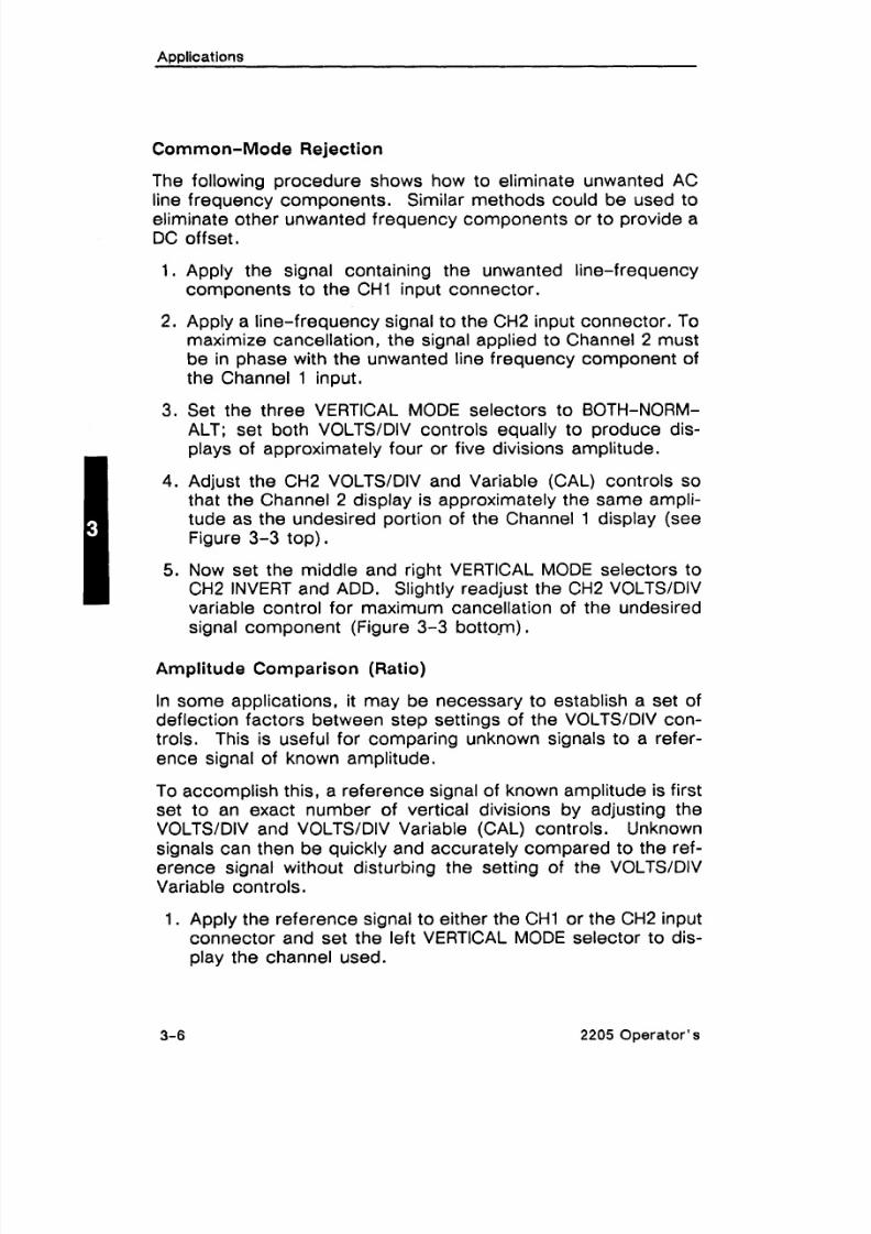
Common-Mode Rejection
The following procedure shows how to eliminate unwanted AC
line frequency components. Similar methods could be used toeliminate other unwanted frequency components or to provide a
DC off set.
1. Apply the signal containing the unwanted line-frequency
components to the CHI input connector.
2. Apply a line-frequency signal to the CH2 input connector. Tomaximize cancellation, the signal applied to Channel 2 mustbe in phase with the unwanted line frequency component ofthe Channel 1 input.
3. Set the three VERTICAL MODE selectors to BOTH-NORM-ALT; set both VOLTSIDIV controls equally to produce dis-plays of approximately four or five divisions amplitude.
4. Adjust the CH2 VOLTSIDIV and Variable (CAL) controls sothat the Channel 2 display is approximately the same ampli-tude as the undesired portion of the Channel 1 display (seeFigure 3-3 top).
5. Now set the middle and right VERTICAL MODE selectors toCH2 INVERT and ADD. Slightly readjust the CH2 VOLTSIDIV
variable control for maximum cancellation of the undesired
signal component (Figure 3-3 bo ttop) .Amplitude Comparison (Ratio)
In some applications, it may be necessary to establish a set of
deflection factors between step settings of the VOLTSIDIV con-trols. This is useful for comparing unknown signals to a refer-
ence signal of known amplitude.
To accomplish this, a reference signal of known amplitude is first
set to an exact number of vertical divisions by adjusting the
VOLTSIDIV and VOLTSIDIV Variable (CAL) controls. Unknownsignals can then be quickly and accurately compared to the ref-erence signal without disturbing the setting of the VOLTSIDIV
Variable controls.
1. Apply the reference signal to either the CHI or the CH2 inputconnector and set the left VERTICAL MODE selector to dis-
play the channel used.
3-6 2205 Operator's

8/14/2019 Qservice ----- This Document is a Complete
http://slidepdf.com/reader/full/qservice-this-document-is-a-complete 49/100
CH 1 SIGNALWITH UNWANTEDLlNE FREQUENCY
COMPONENT
CH 2-SIGNALFROM LINE
FREQUENCYSOURCE
INVERTED
SlGNAL WITHLlNE FREQUENCY
COMPONENTCANCELED
CH 1AND CH 2 SIGNALS
RESULTANT SIGNAL
67 7-01
Figure 3-3. Common-mode rejection.
2. Set the amplitude of the reference signal to 5 vertical divi-sions by adjusting the VOLTS/DIV and VOLTSIDIV Variable(CAL) controls.
3. Disconnect the reference signal and apply the unknown sig-nal to the same channel input. Adjust the vertical position ofthe waveform so that its bottom edge just touches the 0%line on the crt.
4. Horizontally position the waveform so that its topmost fea-tures cross the center vertical graticule line (see Fig-
ure 3-4 ) .
2205 Operator's

8/14/2019 Qservice ----- This Document is a Complete
http://slidepdf.com/reader/full/qservice-this-document-is-a-complete 50/100
Applications
READ PERCENTRATIO (30%)
Figure 3-4. Determining voltage ratio.
5. Read the percent ratio directly from the graduations on thevertical centerline, referring to the 0% and 100% percentagemarks on the left edge of the graticule (1 minor division
equals 4% for a 5-division display).
TIME MEASUREMENTS
Time Duration
To measure time between two points on a waveform, use the
following procedure:
1. Apply the signal to either the CHI or the CH2 input connec-
tor and set the VERTICAL MODE selector to display the chan-nel used.
2. Adjust the TRIGGER LEVEL control to obtain a stable display.
3. Set the SEC/DIV control to display between one and twocomplete repetitions of the waveform. Check that the SEC/
DIV variable control is in the CAL detent.
3-8 2205 Operator's

8/14/2019 Qservice ----- This Document is a Complete
http://slidepdf.com/reader/full/qservice-this-document-is-a-complete 51/100
Applications
4 . Position the display to place the time-measurement points
on the center horizontal graticule line (see Figure 3-5).
- . HORIZONTAL
DISTANCE
1 67 17-08]
Figure 3-5. Measuring time duration.
5. Measure the horizontal distance between the time measure-
ment points.
6. Calculate time duration using the following formula:
horizontal SEC/DIVdistance control
Time -- (divisions) setting
Duration magnification factor
EXAMPLE. In Figure 3-5, the distance between the time meas-urement points is 8.3 divisions, and the SECIDIV setting is 2 msper division, HORIZONTAL MAG is set to X I .
2205 Operator's
8/14/2019 Qservice ----- This Document is a Complete
http://slidepdf.com/reader/full/qservice-this-document-is-a-complete 52/100
Substituting the given values:
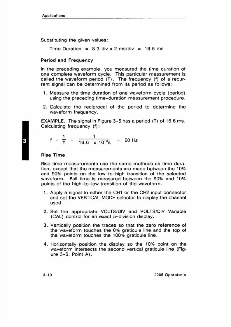
Time Duration = 8.3 div x 2 msldiv = 16.6 ms
Period and Frequency
In the preceding example, you measured the time duration of
one complete waveform cycle. This particular measurement is
called the waveform period (T) . The frequency (f) of a recur-rent signal can be determined from its period as follows:
1. Measure the time duration of one waveform cycle (period)
using the preceding time-duration measurement procedure.
2. Calculate the reciprocal of the period to determine the
waveform frequency.
I'
XAMPLE. The signal in 'Figure 3-5 has a period (T) of 16.6 ms.
Calculating frequency (f) :
1 1f = - -
T - 16.6 I O - ~ S= 60 Hz
Rise Time
Rise time measurements use the same methods as time dura-tion, except that the measurements are made between the 10%and 90% points on the low-to-high transition of the selectedwaveform. Fall time is measured between the 90% and 10%points of the high-to-low transition of the waveform.
1. Apply a signal to either the CHI or the CH2 input connector
and set the VERTICAL MODE selector to display the channel
used.
2. Set the appropriate VOLTSIDIV and VOLTSIDIV Variable(CAL) control for an exact 5-division display.
3. Vertically position the traces so that the zero reference ofthe waveform touches the 0% graticule line and the top of
the waveform touches the 100% graticule line.
4 . Horizontally position the display so the 10% point on the
waveform intersects the second vertical graticule line (Fig-
ure 3-6, Point A).
3-10 2205 Operator's

8/14/2019 Qservice ----- This Document is a Complete
http://slidepdf.com/reader/full/qservice-this-document-is-a-complete 53/100
7-IGNAL
AMPLITUDE
4ORIZONTAL DISTANCE)C
Figure 3-6. Measuring rise time.
NOTE
You can achieve better accuracy by using the
SECIDIV control, or horizontal magnification, to
expand the waveform transition so that it occupiesfrom four to six horizontal divisions between the10% and 90% amplitude points.
5. Measure the horizontal distance between the 10% and 90%points (Figure 3-6, Points A and B) and calculate time dura-tion using the following formula:
horizontal SECIDIVdistance control
Rise -- (divisions) setting
Time magnification factor
EXAMPLE. In Figure 3-6, the horizontal distance between the
10% and 90% amplitude points is 5 divisions, and the SECIDIVswitch is set to 1 ps per division. HORIZONTAL MAG is set to
X I .
2205 Operator's

8/14/2019 Qservice ----- This Document is a Complete
http://slidepdf.com/reader/full/qservice-this-document-is-a-complete 54/100
Substituting given values in the formula:
Rise Time =
5 div x 1 psldiv
1 = 5 ps
Time Difference Between Pulses on Time-Related Signals
The calibrated sweep speed and dual-trace features of the 2205
allow measurement of the time difference between two separate
events. To measure time difference, use the following proce-
dure:
1. Set the TRIGGER SOURCE to CHI.
2. Set both input coupling controls to the same position.
3. Using probes or cables with equal time delays, apply aknown reference signal to the CHI input connector and ap-
ply the comparison signal to the CH2 input.
4 . Set both VOLTSIDIV controls for a display of about five divi-
sions.
5. Set VERTICAL MODE to BOTH; then select either ALT orCHOP, depending on the frequency of the input signals.
6. If the two signals are opposite in polarity, set the middle
VERTICAL MODE selector to CH2 INVERT to invert the Chan-
nel 2 display.
7. Adjust the TRIGGER LEVEL control for a stable display.
8. Set the SECIDIV control to a sweep speed that providesthree or more divisions of horizontal separation betweenmeasurement points on the two displays. Center each of
the displays vertically (see Figure 3-7).
2205Operator's

8/14/2019 Qservice ----- This Document is a Complete
http://slidepdf.com/reader/full/qservice-this-document-is-a-complete 55/100
Applications
CHANNEL 1 (REFERENCE) CHANNEL 2
IHORIZONTAL
I- DIFFERENCE y-1 I
Figure 3-7. Time difference between pulses ontime-related signals.
9. Determine the horizontal difference between the two signalmeasurement points and calculate the time difference usingthe following formula:
horizontal SECJDIVdifference control
Time - (divisions) settingDifference
magnification factor
EXAMPLE. In Figure 3-7, the SECJDIV control is set to 50 psper division and HORIZONTAL MAG is set to X10. The horizontal
difference between waveform measurement points is 4.5 divi-sions.
Time - 50 mldiv x 4.5 divDifference 10
= 22.5 ps
2205 Operator's
8/14/2019 Qservice ----- This Document is a Complete
http://slidepdf.com/reader/full/qservice-this-document-is-a-complete 56/100
Applications
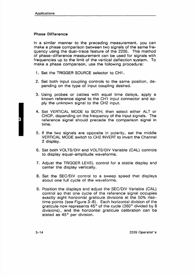
Phase Difference
In a similar manner to the preceding measurement, you can
make a phase comparison between two signals of the same fre-quency using the dual-trace feature of the 2205. This method
of phase-difference measurement can be used for signals withfrequencies up to the limit of the vertical deflection system. To
make a phase comparison, use the following procedure:
1. Set the TRIGGER SOURCE selector to CHI.
2. Set both input coupling controls to the same position, de-
pending on the type of input coupling desired.
3. Using probes or cables with equal time delays, apply a
known reference signal to the CHI input connector and ap-
ply the unknown signal to the CH2 input.
4 . Set VERTICAL MODE to BOTH; then select either ALT or
CHOP, depending on the frequency of the input signals. The
reference signal should precede the comparison signal intime.
5. If the two signals are opposite in polarity, set the middleVERTICAL MODE switch to CH2 INVERT to invert the Channel
2 display.
6. Set both VOLTSIDIV and VOLTSIDIV Variable (CAL) controls
to display equal-amplitude waveforms.
7. Adjust the TRIGGER LEVEL control for a stable display and
center the display vertically.
8. Set the SECIDIV control to a sweep speed that displays
about one full cycle of the waveforms.
9. Position the displays and adjust the SECIDIV Variable (CAL)control so that one cycle of the reference signal occupies
exactly eight horizontal graticule divisions at the 50% rise-
time points (see Figure 3-8). Each horizontal division of the
graticule now represents 45" of the cycle (360" divided by 8divisions), and the horizontal graticule calibration can be
stated as 45" per division.
3-1 4 2205 Operator's

8/14/2019 Qservice ----- This Document is a Complete
http://slidepdf.com/reader/full/qservice-this-document-is-a-complete 57/100
Applications
10. Measure the horizontal difference between corresponding
points on the two waveforms at the 50% rise-time points and
calculate the phase difference using the following formula:
horizontal graticulePhase - difference calibrationDifference - (divisions) (deg/div)
EXAMPLE. In Figure 3-8, the horizontal difference is 0.6 divi-
sion with a graticule calibration of 45" per division.
Substituting the given values into the phase-difference formula:
Phase Difference = 0.6 div x 45Otdiv = 27O.
CHANNEL 1 CHANNEL2(REFERENCE) f (LAGGING)
MEASURETIME FROM A TOB
HORIZONTALDIFFERENCE
Figure 3-8. Phase difference.
2205 Operator's

8/14/2019 Qservice ----- This Document is a Complete
http://slidepdf.com/reader/full/qservice-this-document-is-a-complete 58/100
Applications
More accurate phase measurements can be made by using thehorizontal magnifier function to increase the sweep speed with-
out changing the SECfDIV variable control setting. To do this,
set the HORIZONTAL MAG to X10.
With the sweep speed increased 10 times (MAG set to X I 0) , themagnified horizontal graticule calibration will be 4.5" per division
(45OIdivision divided by 10). Figure 3-9 shows the same signalsillustrated in Figure 3-8, but horizontally magnified by a factor of
10.
EXAMPLE. In Figure 3-9, the 10X magnified display results in a
horizontal difference of six divisions between the two signals.
Substituting the given values into the phase difference formula:
Phase Difference = 6 div x 4.5"Idiv = 27".
I CHANNEL1 (REFERENCE) CHANNEL2 (COMPARISON)
MEASURETIME FROM
ATOB
I- HORIZONTALI DIFFERENCE
+I
6717-1;
Figure 3-9. High-resolution phase difference.
2205 Operator's

8/14/2019 Qservice ----- This Document is a Complete
http://slidepdf.com/reader/full/qservice-this-document-is-a-complete 59/100
Applications
'TELEVlSlON DISPLAYS
T V Field Signals
The 2205 television feature can be used to display TV field sig-
nals. To do so, proceed as follows:
1. Set the TRIGGER MODE selector to TV FIELD and set theSECIDIV control to 2 ms.
2. Apply the television signal to either the CHI or the CH2 input
connector and set the VERTICAL MODE selector to display
the channel used.
3. For positive-going TV signal sync pulses, set the TRIGGERSLOPE to f nd rotate the LEVEL control fully counter-
wise. (Sometimes it may be necessary to move the LEVEL
control slightly clockwise to obtain stable triggering.)
4 . Set the appropriate VOLTSIDIV control to display one divi-sion or more of composite video signal.
5. To change the TV field being displayed, momentarily inter-
rupt the trigger signal by setting the input coupling to GND,
then back to DC or AC until the desired field is displayed.
INOTE
To examine a TV Field signal in more detail, set
HORIZONTAL MAG to X10.
6. To display either Field 1 or Field 2 individually, connect the
television signal to both the CHI and CH2 input connectors
and select BOTH and ALT VERTICAL MODE. Set the SECI
DIV control to 0.5 ms or faster sweep speed (displays lessthan one full field). This will synchronize the Channel 1 dis-
play to one field and the Channel 2 display to the other field.
2205 Opera to r 's

8/14/2019 Qservice ----- This Document is a Complete
http://slidepdf.com/reader/full/qservice-this-document-is-a-complete 60/100
Applications
TV Line Signals
The following procedure is used to display a TV Line signal.
1. Verify that TRIGGER MODE is set to P-P AUTO/TV LINE.
2. Apply the Television signal to either the CHI or the CH2 input
connector and set the VERTICAL MODE selector to displaythe channel used.
3. Set the SECIDIV control to 10 ps.
4 . For positive-going TV signal sync pulses, set the TRIGGER
SLOPE to f nd rotate the LEVEL control fully clockwise.
For negative-going sync pulses, set the TRIGGER SLOPE to'7, and rotate the LEVEL control fully counterclockwise.
(Sometimes it may be necessary to move the LEVEL control
I
lightly clockwise to obtain stable triggering.)
5. Set the appropriate VOLTS/DIV control to display one divi-
sion or more of composite sync signal.
NOTE
To examine a TV Line signal in more detail, set
HORIZONTAL MAG to X10.
6. To display a selected TV Line pulse, first trigger the sweep
on a TV Field sync pulse. Use the HORIZONTAL POSITION
control to select the desired line pulse, then set HORIZON-TAL MAG to X10.
Z-MODULATION
The Z-modulation system can be used to display time markers,
because it depends entirely upon the accuracy of the signal
source. It can also be used in any situation where external con-
trol of the brightness of some or all of the trace is required.
The Z, or intensity, modulation feature is operated in the follow-ing manner:
3-18 2205 Operator's
8/14/2019 Qservice ----- This Document is a Complete
http://slidepdf.com/reader/full/qservice-this-document-is-a-complete 61/100
Applications
1. Set the left and right TRIGGER SOURCE controls to EXT and
EXT=Z, respectively.
2. Apply a signal to either the CHI or the CH2 connector and
set the VERTICAL MODE selector to display the channel
used.
3. Apply the Z-modulation signal to the connector labeled EXTINPUT or Z .
When the Z-modulation and the vertical-input signals are syn-chronized, Z-modulation is seen as gaps in the trace at themodulation frequency. The size of the gap depends upon the
mark-to-space ratio of the Z-modulation signal. The positive-
going portion of the Z-modulation signal decreases display
brightness.
2205 Operator's

8/14/2019 Qservice ----- This Document is a Complete
http://slidepdf.com/reader/full/qservice-this-document-is-a-complete 62/100

8/14/2019 Qservice ----- This Document is a Complete
http://slidepdf.com/reader/full/qservice-this-document-is-a-complete 63/100
SECTION 4
CHECKS AND
ADJUSTMENTS
2205 Operator's

8/14/2019 Qservice ----- This Document is a Complete
http://slidepdf.com/reader/full/qservice-this-document-is-a-complete 64/100

8/14/2019 Qservice ----- This Document is a Complete
http://slidepdf.com/reader/full/qservice-this-document-is-a-complete 65/100
Q s e r v i c e - - - - - T h i s D o c u m e n t i s a c o m p l
e t e s c a n f r o m t
h e O r i g i n a
l T e k t r o n i x M a n u a l - - - - -
Q s e r v i c e

8/14/2019 Qservice ----- This Document is a Complete
http://slidepdf.com/reader/full/qservice-this-document-is-a-complete 66/100
8/14/2019 Qservice ----- This Document is a Complete
http://slidepdf.com/reader/full/qservice-this-document-is-a-complete 67/100
Checks and Adjustments
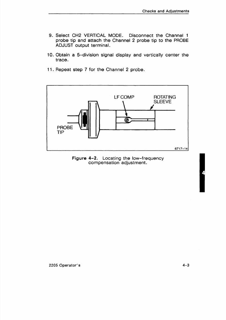
9. Select CH2 VERTICAL MODE. Disconnect the Channel 1
probe tip and attach the Channel 2 probe tip to the PROBEADJUST output terminal.
10. Obtain a 5-division signal display and vertically center thetrace.
11. Repeat step 7 for the Channel 2 probe.
LFCOMP ROTATINGSLEEVE
\@-?
Figure 4-2. Locating the low-frequency
compensation adjustment.
2205 Operator's

8/14/2019 Qservice ----- This Document is a Complete
http://slidepdf.com/reader/full/qservice-this-document-is-a-complete 68/100

8/14/2019 Qservice ----- This Document is a Complete
http://slidepdf.com/reader/full/qservice-this-document-is-a-complete 69/100
SECTION 5
PERFORMANCE
CHARACTERISTICS
2205 Operator's

8/14/2019 Qservice ----- This Document is a Complete
http://slidepdf.com/reader/full/qservice-this-document-is-a-complete 70/100

8/14/2019 Qservice ----- This Document is a Complete
http://slidepdf.com/reader/full/qservice-this-document-is-a-complete 71/100

8/14/2019 Qservice ----- This Document is a Complete
http://slidepdf.com/reader/full/qservice-this-document-is-a-complete 72/100
TABLE 5-1 (cont'd)
VERTICAL DEFLECTION SYSTEM (cont'd)
Characteristics Perform ance Req uireme nts
CHOP Mode Switching 1 500 kHz 5 30%.
Rate
Bandwidth (-3 dB)
+5"C to t35"C
O°C to +5"C and
+35"C to +40°C
AC Coupled Lower CutoffFrequency
Input Characteristics I
20 MHz or more.
15 MHz or more.
10 Hz or less at -3 dB.
Resistance I 1 M a ? 2 % .I
Capacitance 1 25 pF ?2pF.
Maximum Safe InputVoltage (DC or ACCou~led)
Trace Shift
400 V (dc + peak ac) or 800 Vac p-p to 10 kHz or less.
Common-Mode RejectionRatio (CMRR)
With VOLTSIDIVSwitch Rotation
At least 10 to 1 at 20 MHz.
0.75 division or less (Variablecontrol in CAL detent).
With VOLTSIDIV Variable 1 1.0 division or less.Control Rotation IWith Channel 2 I 1.5 divisions or less.Inverted
2205 Operator's
Channel Isolation Greater than 100 to 1at 10 MHz.

8/14/2019 Qservice ----- This Document is a Complete
http://slidepdf.com/reader/full/qservice-this-document-is-a-complete 73/100
Performance Characteristics
TABLE 5-1 (cont'd)
TRIGGER SY ST EM
Characteristics
Trigger Sensitivity
Performance Requirements
Lowest UsableFrequency in P-P
AUTO Mode
P-P AUTO/TV LINEand NORM Modes
Internal Signal
External Signal
Resistance I 1 M i l 2 10%.
5 MHz
0.3div
40 mV
TV FIELD Mode
External Input
Capacitance 1 25 pF 22.5 F.
30 MHz
1.0div
150 mV
1.0division of composite sync.
Maximum Voltage I 400 V (dc + peak ac) or 800 Vac p-p at 10 kHz or less.
Trigger Level Range I
2205 Operator's
NORM Mode
EXT Source
+_I5 divisions referred to theappropriate vertical input.
At least 2 1.6V, 3.2 V p-p.
8/14/2019 Qservice ----- This Document is a Complete
http://slidepdf.com/reader/full/qservice-this-document-is-a-complete 74/100
Performance Characteristics
TABLE 5-1 (cont'd)
HORIZONTAL DEFLECTION SYSTEM
Characteristics
Sweep Rate
Calibrated Range
Performance Requirements
Accuracy
Variable Control Range
Sweep Linearity
Position Control Range
Registration of Unmagni-fied and Magnified Traces
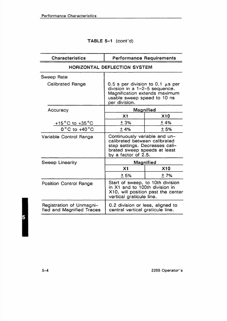
0.5 s per division to 0.1 ps perdivision in a 1-2-5 sequence.Magnification extends maximumusable sweep speed to 10 nsper division.
Ma nified
+ 3% + 4%
5 4 % 2 5%2ontinuously variable and un-
calibrated between calibratedstep settings. Decreases cali-brated sweep speeds at leastby a factor of 2.5.
Ma nified
2 7%
Start of sweep, to 10th divisionin XI and to 100th division inX10, will position past the centervertical graticule line.
0.2 division or less, aligned tocentral vertical graticule line.
2205 Operator's
8/14/2019 Qservice ----- This Document is a Complete
http://slidepdf.com/reader/full/qservice-this-document-is-a-complete 75/100
Performance Characteristics
TABLE 5-1 (cont'd)
Z-MODULATION
Characteristics Performance Requirements
Sensitivity
Usable Frequency Range
X-Y OPERATION (X I MOD E)
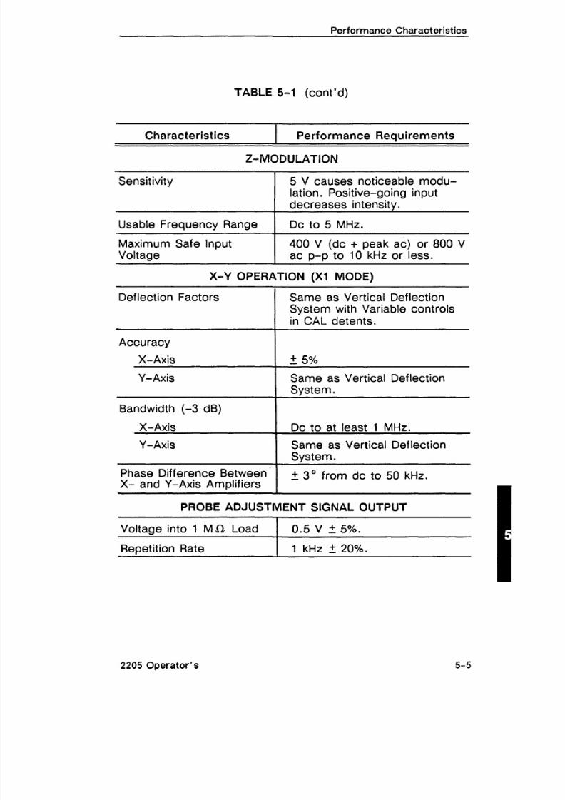
5 V causes noticeable modu-lation. Positive-going inputdecreases intensity.
Dc to 5 MHz.
Maximum Safe InputVoltage
Deflection Factors
400 V (dc + peak ac) or 800 Vac p-p to 10 kHz or less.
Same as Vertical DeflectionSystem with Variable controlsin CAL detents.
Accuracy
X- Axis
Bandwidth (-3 dB) IY- Axis
X- Axis I Dc to at least 1 MHz.I
Same as Vertical DeflectionSystem.
PROBE ADJUSTMENT SIGNAL OUTPUT
Y-Axis
Phase Difference BetweenX- and Y-Axis Amplifiers
Voltage into 1 M i l Load 1 0.5 V 2 5%.
I
Same as Vertical DeflectionSystem.
+ 3 O f rom dc to 50 k ~ z .
Re~etitionRate I 1 kHz It20%.
2205 Operator 's
8/14/2019 Qservice ----- This Document is a Complete
http://slidepdf.com/reader/full/qservice-this-document-is-a-complete 76/100
Performance Characteristics
TABLE 5-1 (cont'd)
POWER REQUIREMENTS
Characteristics
Line Voltage Ranges
Performance Requirements
1 15 V Settina
230 V Setting
Line Frequency
Maximum PowerConsumption
Line Fuse
115 V Setting
230 V Setting
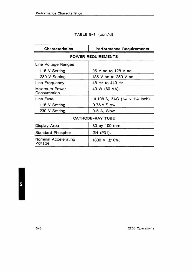
95 V ac to 128 V ac.
185 V ac to 250 V ac.
48 Hz to 440 Hz.
40 W (60 VA) .UL198.6, 3AG (114 x 1% inch)
0.75 A Slow
0.5 A, Slow
CATHODE-RAY TUBE
Display Area 1 80 by 100 mm.
Standard Phosphor I GH (P31).I
2205 Operator's
Nominal AcceleratingVoltage
1800 V 510%.
8/14/2019 Qservice ----- This Document is a Complete
http://slidepdf.com/reader/full/qservice-this-document-is-a-complete 77/100
Performance Characteristics
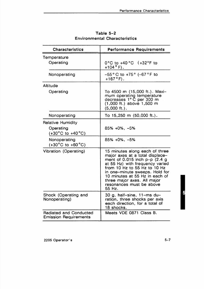
Table 5-2
Environmental Characteristics
Altitude
Operating
Characteristics
Temperature
Operating
Nonoperating
To 4500 m (15,000 ft.). Maxi-
mum operating temperaturedecreases 1" C per 300 m(1,000 ft.) above 1,500 m
(5,000 ft.).
Performance Requirements
0°C to +40 "C (t32"F to+lo4 O F).
-55 O C to +75 O (-67 O F tot167OF).
Vibration (Operating)
Nonoperating
Relative Humidity
Operating
(+30°C to +40 "C)
Nonoperating
(+30°C to +60°C)
Shock (Operating andNonoperating)
- -To 15,250 m (50,000 ft.).
85% to%, -5%
85% +O%, -5%
Radiated and ConductedEmission Requirements
major axes at atotal displace-ment of 0.015 inch p-p (2.4 gat 55 Hz) with frequency variedfrom 10 Hz to 55 Hz to 10 Hzin one-minute sweeps. Hold for10 minutes at 55 Hz in each ofthree major axes. All majorresonances must be above55 Hz.
30 g, half-sine, 11-ms du-ration, three shocks per axiseach direction, for a total of18 shocks.
Meets VDE 0871 Class B.
2205 Operator's 5-7

8/14/2019 Qservice ----- This Document is a Complete
http://slidepdf.com/reader/full/qservice-this-document-is-a-complete 78/100
Performance Characteristics
Table 5-3
Mechanical Characteristics
Characteristics I Performance Requirements--Weight With Power Cord
Height 1 138 mm (5.4 in).
8.25 kg ( 13.7 lbs ) or less.
Domestic Shipping Weight
Width
With Handle
9.1 kg (20.0 Ibs) or less.
Without Handle1
327 mm (12.9 in).Depth I
With HandleExtended
Without Front Cover
With Optional FrontCover
10kHz 50kHz 100kHz 500 kHz 1 MHz 100MHz
FREQUENCY
441 mm ( 17.4 in ).
455 mm ( 17.9 in ).
Figure 5-1. Maximum input voltage versus frequency deratingcurve for CH 1 OR X, CH 2 OR Y, and EXT INPUT connectors.
5-8 2205 Operator's

8/14/2019 Qservice ----- This Document is a Complete
http://slidepdf.com/reader/full/qservice-this-document-is-a-complete 79/100
SECTION 6
OPTIONS ANDACCESSORIES
2205 Operator's I

8/14/2019 Qservice ----- This Document is a Complete
http://slidepdf.com/reader/full/qservice-this-document-is-a-complete 80/100

8/14/2019 Qservice ----- This Document is a Complete
http://slidepdf.com/reader/full/qservice-this-document-is-a-complete 81/100
Q s e r v i c e - - - - - T h i s D o c u m e n t i s a c o m p l
e t e s c a n f r o m t
h e O r i g i n a
l T e k t r o n i x M a n u a l - - - - -
Q s e r v i c e

8/14/2019 Qservice ----- This Document is a Complete
http://slidepdf.com/reader/full/qservice-this-document-is-a-complete 82/100

8/14/2019 Qservice ----- This Document is a Complete
http://slidepdf.com/reader/full/qservice-this-document-is-a-complete 83/100

8/14/2019 Qservice ----- This Document is a Complete
http://slidepdf.com/reader/full/qservice-this-document-is-a-complete 84/100
Options and Accessories
TABLE 6-1
Power Cords and Fuses
Description
Standard (United States)
Power Cord, 2.5 m
Fuse, 0.75 A,250 V,3AG, V4" x 1 /4", Slow
Option A1 (UniversalEurope)
Power Cord. 2.5 m
Fuse, 0.5 A, 250 V ,
3AG, 114"x 1 /d; Slow
Option A2 (UnitedKingdom)
Power Cord, 2.5 m
Fuse, 0.5 A, 250 V,3AG, l14" x 11/4", Slow
Option A3 (Australia)
Power Cord. 2.5 mFuse, 0.5 A, 250 V,3AG, V4" x 1W: Slow
Option A4 (North America)
Power Cord, 2.5 m
Fuse, 0.5 A, 250 V,3AG, 114" x 11/4", Slow
Option A5 (Switzerland)
Power Cord, 2.5 mFuse, 0.5 A , 250 V,3AG, 114" x 11/4", Slow
Part Number
2205 Operator's

8/14/2019 Qservice ----- This Document is a Complete
http://slidepdf.com/reader/full/qservice-this-document-is-a-complete 85/100
Options and Accessories
OPTIONAL ACCESSORIES
Table 6-2 lists recommended optional accessories for your in-strument.
TABLE 6-2
Optional Accessories
Front Panel Protective Cover
Accessory Pouch
Front Panel Protective Coverand Accessory Pouch
Hand Carrying Case
CRT Light Filter, Clear
Rack Mount Conversion Kit
Viewing Hoods
Collapsible
Polarized
Binocular
Probe, 10X, 2 m, withaccessories
Alternative Power Cords
European
United Kingdom
Australian
North AmericanSwitzerland
2205 Operator's
Part Number

8/14/2019 Qservice ----- This Document is a Complete
http://slidepdf.com/reader/full/qservice-this-document-is-a-complete 86/100

8/14/2019 Qservice ----- This Document is a Complete
http://slidepdf.com/reader/full/qservice-this-document-is-a-complete 87/100
APPENDIX AMagnified Sweep Speeds
SEClDlVSetting
Magnified Sweep Speed(TimelDivision)
X I 0
50 ms
20 ms
10ms
5 ms
2 ms
1 ms
.5 ms
.2 ms
.1 ms
50 ps
20 ps
10 ps
5 JIS
2 PS
1 JIS
.5 JIS
.2 ps
. I ps
50 ns
20 ns
10 ns
2205 Operator's

8/14/2019 Qservice ----- This Document is a Complete
http://slidepdf.com/reader/full/qservice-this-document-is-a-complete 88/100
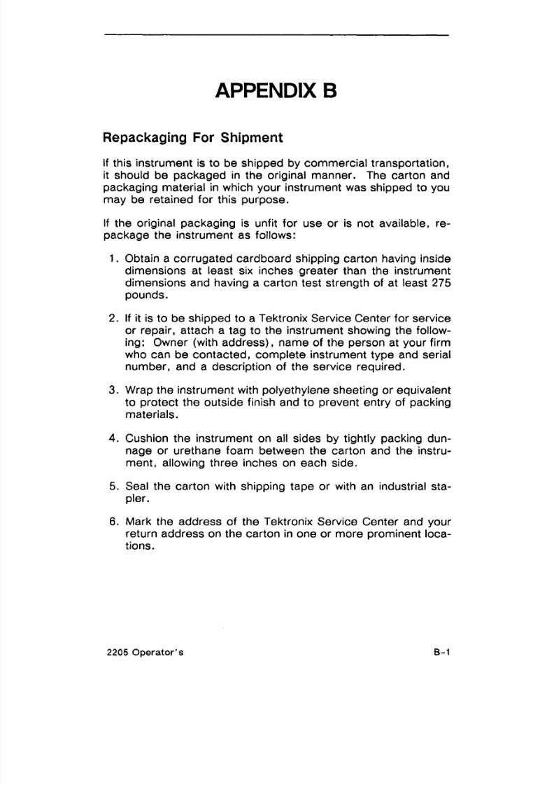
8/14/2019 Qservice ----- This Document is a Complete
http://slidepdf.com/reader/full/qservice-this-document-is-a-complete 89/100

8/14/2019 Qservice ----- This Document is a Complete
http://slidepdf.com/reader/full/qservice-this-document-is-a-complete 90/100

8/14/2019 Qservice ----- This Document is a Complete
http://slidepdf.com/reader/full/qservice-this-document-is-a-complete 91/100
APPENDIX C
GLOSSARY
DISPLAY CONTROLS
BEAM FIND-Finds the beam when it is off the screen.
FOCUS-Adjusts the trace for optimum focus.
INTENSITY-Adjusts the brightness of the trace.
POWER (ON-OFF)-Turns on AC power to the power supply.When the light is on the instrument operates; when the light is
off the instrument is off.
TRACE ROTATION-Adjusts the trace to be parallel with the fixed
graticule. (See OTHERS for graticule) .
VERTICAL CONTROLS
ADD-Combines Channel 1 and Channel 2 algebraically.
ALTERNATE (ALT)-Shows CH 1 and CH 2 alternately; first onesweep of Channel 1 then one sweep of Channel 2.
Alternating Coupling (AC)-Static signal components are
blocked and only the alternating components of the input signal
reach the channel.
BOTH-Displays CH 1 and CH 2 in ALT, CHOP, or ADD mode.
CAL-Changes the variable scale factor up to 2.5 times the
VOLTS/DIV setting.
Channel 1 (CH 1)-Displays only Ch 1 on the screen.
Channel 2 (CH 2)-Displays only Ch 2 on the screen.
Channel 2 Invert (CH 2 INVERT)-Inverts the polarity of CH 2.
(See OTHERS for polarity.)
CHOP-The scope will draw part of CH 1 , then part of CH 2 by
switching back and forth.
2205 Operator's

8/14/2019 Qservice ----- This Document is a Complete
http://slidepdf.com/reader/full/qservice-this-document-is-a-complete 92/100
Channel 1 VoltslDivision (CH 1 VOLTS1DIV)-This switch is the
scale factor for CH 1 .
Channel 2 VoltsIDivision (CH 2 VOLTS1DIV)-This switch is thescale factor for CH 2.
Direct Coupling (DC)-All components of the input signal reach
the input channel.
GROUND (/)I)-Shows where the zero level will be located when
shifted to AC or DC.
Normal (NORM)-CH 1 and Ch 2 both have the same polarity
when set to NORM. (See OTHERS for polarity.)
POSITION-Moves the trace vertically on the screen.
HORIZONTAL CONTROLS
CAL-Reduces the SEClDlV by up to 2.5 :1 .
Ground receptacle-Provides safety earth connection to signal
source.
Magnified times 1 (MAG XI)-Magnifies the SECIDIV by 1.
Magnified times 10 (MAG X10)-Magnifies the SECIDIV by 10.
POSITION-Moves the trace horizontally on the screen.
PROBE ADJUST-Provides a square wave for use as a reference
when adjusting compensation on 1OX probes.
SecondsIDivision (SEC1DIV)-Lets you select the rate at which
the beam sweeps across the screen.
TRIGGER CONTROLS
Channel 1 (CH 1)-Selects CH 1 signals to trigger the time base.
Channel 2 (CH 2)-Selects CH 2 signals to trigger the time base.
External (EXT)-Selects external signals to trigger the time base.
External 10 (EXTI 10) -Selects external signal, divides it by 10,
and connects it to the trigger circuit.
LEVEL-Determines signal level at which the trigger will occur.
C-2 2205 Operator's
8/14/2019 Qservice ----- This Document is a Complete
http://slidepdf.com/reader/full/qservice-this-document-is-a-complete 93/100
LINE-Another trigger source (the power line).
Normal (NORM) -Allows selection of any TRIGGER LEVEL within
approximately +I 5 divisions.
Peak to Peak Automatic (P-P AUTO)-Limits TRIGGER LEVEL to
a range determined by peaks of signal. If no signal appears in
about 5 ms, the sweep starts on its own to show a "baseline."
RESET-This button is used only in SGL SWP Mode to reset the
sweep. (See TRIGGER for single sweep.)
Single Sweep (SGL SWP)-A mode in which, when a trigger oc-
curs, only one sweep will run.
SLOPE-Determines whether the trigger point will occur on the
raising or falling edge of the signal.
Trigger Ready (TRIG'D)-Lights when the sweep is triggered.
Television Field (TV FIELD) -Trigger on tv fields.
Television Line (TV LINE)-Trigger on tv lines.
Vertical Mode (VERT MODE)-Trigger source is determined by
the Vertical Mode..
OTHERS
Alternation-A change in polarity, like a positive (+) changing
directions to a negative (-) and back again.
Cathode-Ray Tube (CRT) -The picture tube.
Divisions-The lines that divide CRT display area units into X and
Y components.
Graticule-The square boxes formed by lines on the CRT face.
Hertz-The basic unit of frequency.
Ohm (a)--The basic unit of resistance.
Polarity-The positive (+) or negative (- ) direction of voltage or
current.
2205 Operator's

8/14/2019 Qservice ----- This Document is a Complete
http://slidepdf.com/reader/full/qservice-this-document-is-a-complete 94/100
For further information, contact:
U. S. A. , Asia, Australia, Central & SouthAmerica, JapanTektronix, Inc.
P. 0. Box 1700
Beaverton, Oregon 97075
For additional literature, or the address and phone
number of the Tektronix Sales Office nearest you,contact:
Phone: (800) TEK-WIDE
Telex: (910) 467-8708
TLX: 151754
Cable: TEKWSGT
Europe, Africa, Middle EastTektronix Europe B. V.
European Headquarters
Postbox 827
1180 AV Amstelveen
The Netherlands
Phone: (20) 471 146
Telex: 18312-1 8328
CanadaTektronix Canada inc.
P. 0. Box 6500
Barrie, Ontario L4M 4V3
Phone: (705) 737-2700
Tektronix sales and service offices aroundthe world:Albania, Algeria, Angola, Argentina, Australia, Austria,
Bangladesh, Belgium, Bolivia, Brazil, Bulgaria, Canada,
Peoples Republic of China, Chile, Colombia, Costa Rica,
Czechoslovakia, Denmark, East Afr ica, Ecuador, Egypt,
Federal Republic of Germany, Fiji AWA New Zealand,
Finland, France, Greece, Hong Kong, Hungary, Iceland,
India, Indonesia, Ireland, Israel, Italy, Ivory Coast, Japan,
Jordan, Korea, Kuwait, Lebanon, Malaysia, Mexico,
Morocco, The Netherlands, New Zealand, Nigeria,
Norway, Pakistan, Panama, Peru, Philippines, Poland,
Portugal, Qatar, Republic of South Africa, Rumania,
Saudi Arabia, Singapore, Spain, Sri Lanka, Sudan,
Sweden, Switzerland, Syria, Taiwan, Thailand, Turkey,
Tunisia, United Arab Emira tes, United Kingdom, Uruguay,
USSR, Venezuela, Yugoslavia, Zambia, Zimbabwe.
Copyri h t@ 1987, Tektronix , Inc. All rights reserved.
Printej in U. S. A. Tektronix products are covered by U. S.
and foreign patents, issued and pending. Information in
this publication supersedes that in all previously published
material. Specificat ion and price change privileges
reserved. TEKTRONIX, TEK, SCOPE-MOBILE, andTELEQUIPMENT are registered trademarks. For further
information, contact : Tektronix, Inc, Corporate Offices,
P.O. Box 500, Beaverton, OR 97077. Phone (503)
627-7111; TLX: 151754; TW X: (910) 467-8708; Cable:
TEKWSGT; Subsidiaries and distributors worldwide.
COMMITTED TO EXCELLENCE
8/14/2019 Qservice ----- This Document is a Complete
http://slidepdf.com/reader/full/qservice-this-document-is-a-complete 95/100
MANUAL CHANGE INFORMATION
At Tektronix, we continually strive to keep up with latest electronicdevelopments
by adding circui t and component improvements to our instruments as soon as they
are developed and tested.
Sometimes, due to printing and shipping requirements, we can't get these
changes immediately into printed manuals. Hence, your manual may contain new
change information on follow ing pages.
A single change may affect several sections. Since the change info rmation sheets
are carried in the manual until all changes are permanently entered, some
duplication may occur. If no such change pages appear following this page, your
manual is correct as printed.

8/14/2019 Qservice ----- This Document is a Complete
http://slidepdf.com/reader/full/qservice-this-document-is-a-complete 96/100

8/14/2019 Qservice ----- This Document is a Complete
http://slidepdf.com/reader/full/qservice-this-document-is-a-complete 97/100
Rktronbc+ MANUAL CHANGE INFORMATIOND Q e * n B ) m v
Date:02-01 -90 Change Reference: C1/0290
q-oduct: 2205 Operators Manual Manual Part Number:070-6717-00-- -- - -DESCRIPTION Product Group
EFFECTIVE ALL SERIAL NUMBERS
Change page 6-2 to read:
Option 23
Two P6119 1X- 1OX Selectable-attenuation Probes areprovided in place of the standardP6103 10X Probes.
Option 24
Two P6lO3 ,dc to 50 MHz, 1OX Modular Probes are pro-vided.
Change page6-6:
Table 6-2 (cont'd)
Attenuator Voltage Probes1OX Standard10X Submininature10X Environmental1X-1OX Selectable100X High Voltage1000X High Voltage
Part Number
Page 1 of 1

8/14/2019 Qservice ----- This Document is a Complete
http://slidepdf.com/reader/full/qservice-this-document-is-a-complete 98/100
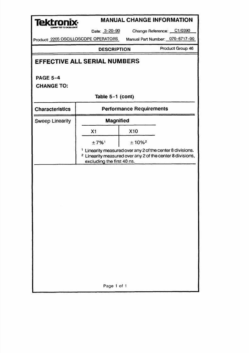
8/14/2019 Qservice ----- This Document is a Complete
http://slidepdf.com/reader/full/qservice-this-document-is-a-complete 99/100
MANUAL CHANGE INFORMATION
Date: 3-20-90 Change Reference: C1 0390
Product: 2205 OSCILLOSCOPE OPERATORS Manual Part Number: 070-6717-00
DESCRIPTION Product Group 46
EFFECTIVE ALL SERIAL NUMB ERS
I PAGE 5-4
CHANGE TO:
Characteristics
Sweep Linearity
Table 5-1 (cont)
Performance Requirements
MagnifiedI
Linearity measured over any 2of the center8divisions.
Linearity measured over any 2 of thecenter 8divisions,
excluding the first 40 ns.
Page 1 of 1

8/14/2019 Qservice ----- This Document is a Complete
http://slidepdf.com/reader/full/qservice-this-document-is-a-complete 100/100