Embed Size (px)
Citation preview
QoS: Policing and Shaping ConfigurationGuide, Cisco IOS Release 12.4T
Americas HeadquartersCisco Systems, Inc.170 West Tasman DriveSan Jose, CA 95134-1706USAhttp://www.cisco.comTel: 408 526-4000 800 553-NETS (6387)Fax: 408 527-0883

THE SPECIFICATIONS AND INFORMATION REGARDING THE PRODUCTS IN THIS MANUAL ARE SUBJECT TO CHANGE WITHOUT NOTICE. ALL STATEMENTS,INFORMATION, AND RECOMMENDATIONS IN THIS MANUAL ARE BELIEVED TO BE ACCURATE BUT ARE PRESENTED WITHOUT WARRANTY OF ANY KIND,EXPRESS OR IMPLIED. USERS MUST TAKE FULL RESPONSIBILITY FOR THEIR APPLICATION OF ANY PRODUCTS.
THE SOFTWARE LICENSE AND LIMITED WARRANTY FOR THE ACCOMPANYING PRODUCT ARE SET FORTH IN THE INFORMATION PACKET THAT SHIPPEDWITH THE PRODUCT AND ARE INCORPORATED HEREIN BY THIS REFERENCE. IF YOU ARE UNABLE TO LOCATE THE SOFTWARE LICENSE OR LIMITEDWARRANTY, CONTACT YOUR CISCO REPRESENTATIVE FOR A COPY.
The Cisco implementation of TCP header compression is an adaptation of a program developed by the University of California, Berkeley (UCB) as part of UCB’s public domain versionof the UNIX operating system. All rights reserved. Copyright © 1981, Regents of the University of California.
NOTWITHSTANDING ANY OTHER WARRANTY HEREIN, ALL DOCUMENT FILES AND SOFTWARE OF THESE SUPPLIERS ARE PROVIDED “AS IS” WITH ALLFAULTS. CISCO AND THE ABOVE-NAMED SUPPLIERS DISCLAIM ALL WARRANTIES, EXPRESSED OR IMPLIED, INCLUDING, WITHOUT LIMITATION, THOSE OFMERCHANTABILITY, FITNESS FOR A PARTICULAR PURPOSE AND NONINFRINGEMENT OR ARISING FROM A COURSE OF DEALING, USAGE, OR TRADEPRACTICE.
IN NO EVENT SHALL CISCO OR ITS SUPPLIERS BE LIABLE FOR ANY INDIRECT, SPECIAL, CONSEQUENTIAL, OR INCIDENTAL DAMAGES, INCLUDING,WITHOUT LIMITATION, LOST PROFITS OR LOSS OR DAMAGE TO DATA ARISING OUT OF THE USE OR INABILITY TO USE THIS MANUAL, EVEN IF CISCO ORITS SUPPLIERS HAVE BEEN ADVISED OF THE POSSIBILITY OF SUCH DAMAGES.
Cisco and the Cisco logo are trademarks or registered trademarks of Cisco and/or its affiliates in the U.S. and other countries. To view a list of Cisco trademarks, go to this URL: www.cisco.com/go/trademarks. Third-party trademarks mentioned are the property of their respective owners. The use of the word partner does not imply a partnership relationshipbetween Cisco and any other company. (1110R)
Any Internet Protocol (IP) addresses and phone numbers used in this document are not intended to be actual addresses and phone numbers. Any examples, command display output,network topology diagrams, and other figures included in the document are shown for illustrative purposes only. Any use of actual IP addresses or phone numbers in illustrative contentis unintentional and coincidental.
© 2012 Cisco Systems, Inc. All rights reserved.
C O N T E N T S
Policing and Shaping Overview 1
Finding Feature Information 1
What Is a Token Bucket 2
Policing with CAR 3
How CAR Works 3
Matching Criteria 3
Rate Limits 4
What Rate Limits Define 4
Extended Burst Value 4
How Extended Burst Capability Works 5
Recommended Burst Values 5
Actual and Compounded Debt Example 5
Conform and Exceed Actions 6
Multiple Rate Policies 6
Restrictions of CAR and VIP-Distributed CAR 7
Traffic Policing 7
Benefits of Traffic Policing 8
Restrictions for Traffic Policing 8
Prerequisites for Traffic Policing 9
Traffic Shaping to Regulate Packet Flow 9
Configuring Traffic Policing 11
Finding Feature Information 11
Feature Overview 11
Benefits 12
Restrictions 13
Supported Platforms 13
Supported Standards MIBs and RFCs 14
Prerequisites 14
Configuration Tasks 14
QoS: Policing and Shaping Configuration Guide, Cisco IOS Release 12.4T iii

Configuring Traffic Policing 15
Troubleshooting Tips 15
Monitoring and Maintaining Traffic Policing 15
Configuration Examples 15
Example Configuring a Service Policy that Includes Traffic Policing 16
Two-Rate Policer 17
Finding Feature Information 17
Prerequisites for Two-Rate Policer 17
Restrictions for Two-Rate Policer 18
Information About Two-Rate Policer 18
Benefits 19
How to Use the Two-Rate Policer 20
Configuring the Two-Rate Policer 20
Verifying the Two-Rate Policer Configuration 21
Troubleshooting Tips 21
Monitoring and Maintaining the Two-Rate Policer 21
Configuration Examples 21
Example Limiting the Traffic Using a Policer Class 21
Additional References 22
Feature Information for Two-Rate Policer 23
Policer Enhancement - Multiple Actions 25
Finding Feature Information 25
Feature Overview 25
Benefits 26
Restrictions 26
Related Features and Technologies 26
Related Documents 26
Supported Platforms 27
Supported Standards MIBs and RFCs 27
Prerequisites 28
Configuration Tasks 28
Configuring Multiple Policer Actions 28
Verifying the Multiple Policer Actions Configuration 28
Troubleshooting Tips 29
Monitoring and Maintaining the Multiple Policer Actions 29
Contents
QoS: Policing and Shaping Configuration Guide, Cisco IOS Release 12.4Tiv

Configuration Examples 29
Example Multiple Actions in a Two-Rate Policer 29
Example Verifying the Multiple Policer Actions 30
Percentage-Based Policing and Shaping 31
Finding Feature Information 31
Feature Overview 31
Benefits 32
Restrictions 32
Related Features and Technologies 32
Related Documents 32
Supported Standards MIBs and RFCs 33
Prerequisites 33
Configuration Tasks 34
Configuring Policing and Shaping Based on Bandwidth Percentage 34
Attaching the Policy Map to an Interface or a VC 35
Verifying the Policing and Shaping Bandwidth Percentage Setting 35
Troubleshooting Tips 35
Configuration Examples 35
Example Specifying Traffic Policing Based on a Bandwidth Percentage 35
Example Specifying Traffic Shaping Based on a Bandwidth Percentage 36
Example Verifying That CEF Is Enabled 36
Modular QoS CLI Three-Level Hierarchical Policer 39
Finding Feature Information 39
Restrictions for the Modular QoS CLI Three-Level Hierarchical Policer 40
Information About the Modular QoS CLI Three-Level Hierarchical Policer 41
Modular Quality of Service Command-Line Interface 41
Packet Flow in the Modular QoS CLI Three-Level Hierarchical Policer 42
Other Traffic Policing-Related Features 42
How to Configure the Modular QoS CLI Three-Level Hierarchical Policer 43
Configuring Traffic Policing 43
Attaching the Policy Map to an Interface 44
What to Do Next 46
Verifying the Configuration 46
Troubleshooting Tips 47
Configuration Examples for the Modular QoS CLI Three-Level Hierarchical Policer 48
Contents
QoS: Policing and Shaping Configuration Guide, Cisco IOS Release 12.4T v

Example Configuring the Modular QoS CLI Three-Level Hierarchical Policer 48
Additional References 50
ATM Policing by Service Category for SVC and SoftPVC 53
Finding Feature Information 53
Feature Overview 53
Benefits 54
Related Features and Technologies 54
Related Documents 54
Supported Platforms 54
Supported Standards MIBs and RFCs 54
Configuration Tasks 55
Configuring ATM Policing by Service Category for SVC and SoftPVC 55
Verifying ATM Policing by Service Category for SVC and SoftPVC 55
Troubleshooting Tips 56
Monitoring and Maintaining ATM Policing by Service Category for SVC and SoftPVC 57
Example Monitoring and Maintaining ATM Policing by Service Category for SVC and
SoftPVC 57
Configuration Examples 58
Example Non-UBR Traffic Policing 58
Modular QoS CLI Unconditional Packet Discard 59
Finding Feature Information 59
Feature Overview 59
Benefits 60
Restrictions 60
Related Features and Technologies 60
Related Documents 60
Supported Standards MIBs and RFCs 60
Configuration Tasks 61
Configuring the Class Map 61
Creating a Policy Map 62
Attaching the Policy Map to an Interface or a VC 63
Verifying the Discard Action Configuration in the Traffic Class 64
Configuration Examples 64
Example Configuring the Discard Action Configuration in a Traffic Class 64
Example Verifying the Discard Action Configuration in the Policy Map 64
Control Plane Policing 67
Contents
QoS: Policing and Shaping Configuration Guide, Cisco IOS Release 12.4Tvi

Finding Feature Information 67
Prerequisites for Control Plane Policing 67
Restrictions for Control Plane Policing 67
Information About Control Plane Policing 69
Benefits of Control Plane Policing 69
Terms to Understand 70
Control Plane Security and Packet QoS Overview 71
Aggregate Control Plane Services 72
Distributed Control Plane Services 73
Usage of Distributed CP Services 74
Output Rate-Limiting and Silent Mode Operation 75
How to Use Control Plane Policing 75
Defining Aggregate Control Plane Services 75
Defining Distributed Control Plane Services 77
Verifying Aggregate Control Plane Services 78
Verifying Distributed Control Plane Services 79
Configuration Examples for Control Plane Policing 81
Example Configuring Control Plane Policing on Input Telnet Traffic 81
Example Configuring Control Plane Policing on Output ICMP Traffic 81
Additional References 82
Feature Information for Control Plane Policing 83
Control Plane Protection 87
Finding Feature Information 87
Prerequisites for Control Plane Protection 87
Restrictions for Control Plane Protection 88
Information About Control Plane Protection 89
Benefits of Control Plane Protection 89
Control Plane Protection Architecture 90
Control-plane Interface and Subinterfaces 90
Control-plane Port-filtering 91
Control-plane Queue-thresholding 91
Aggregate Control-plane Services 92
Control Plane Protection Configuration 92
How to Configure Control Plane Protection 92
Defining Packet Classification Criteria for CoPP 93
Contents
QoS: Policing and Shaping Configuration Guide, Cisco IOS Release 12.4T vii
Defining a CoPP Service Policy 94
Entering Control Plane Configuration Mode 96
Applying CoPP Service Policy 97
Configuring Port-filter Policy 98
Restrictions 98
Defining Port-filter Packet Classification Criteria 99
Defining Port-filter Service Policy 100
Applying Port-filter Service Policy to the Host Subinterface 101
Examples 102
Configuring Queue-threshold Policy 103
Restrictions 103
Defining Queue-threshold Packet Classification Criteria 103
Defining a Queue-threshold Service Policy 105
Applying a Queue-threshold Policy to the Host Subinterface 106
Examples 107
Verifying Control Plane Protection 108
Examples 109
Additional References 109
Feature Information for Control Plane Protection 110
Control Plane Logging 113
Finding Feature Information 113
Prerequisites for Control Plane Logging 113
Restrictions for Control Plane Logging 114
Information About Control Plane Logging 114
Global Control Plane Logging 114
Feature-Specific or Class-Specific Logging 115
Global Logging Configuration 115
How to Configure Logging on a Control Plane Interface 116
Defining Packet Logging Classification Criteria for Global Logging 116
Defining the Logging Policy Map for Global Logging 118
Creating a Logging Service Policy on a Control Plane Interface for Global Logging 119
Configuring Feature-Specific or Class-Specific Logging 120
Verifying Control Plane Logging Information 122
Verification Examples for Control Plane Logging 123
Sample Output for a Global Logging Configuration 123
Contents
QoS: Policing and Shaping Configuration Guide, Cisco IOS Release 12.4Tviii

Sample Output for a Feature-Specific or Class-Specific Configuration 124
Sample Log Output 124
Configuration Examples for Control Plane Logging 125
Configuring Global Control Plane Logging for Dropped and Permitted Packets Example 125
Configuring Global Control Plane Logging for Dropped Packets Example 126
Configuring Logging for a Specific Class Example 126
Configuring Logging for a Port-Filter Policy Map Example 127
Additional References 128
Feature Information for Control Plane Logging 129
Class-Based Policing 131
Finding Feature Information 131
Feature Overview 132
Benefits 132
Restrictions 133
Prerequisites 133
Configuration Tasks 133
Configuring Traffic Policing 134
Verifying Traffic Policing 134
Troubleshooting Tips 134
Monitoring and Maintaining Traffic Policing 134
Configuration Examples 135
Example Configuring a Service Policy that Includes Traffic Policing 135
Additional References 136
QoS Percentage-Based Policing 139
Finding Feature Information 139
Prerequisites for QoS Percentage-Based Policing 139
Restrictions for QoS Percentage-Based Policing 139
Information About QoS Percentage-Based Policing 140
Benefits for QoS Percentage-Based Policing 140
Defining Class and Policy Maps for QoS Percentage-Based Policing 140
Traffic Regulation Mechanisms and Bandwidth Percentages 141
Burst Size in Milliseconds Option 141
How to Configure QoS Percentage-Based Policing 141
Configuring a Class and Policy Map for Percentage-Based Policing 142
Attaching the Policy Map to an Interface for Percentage-Based Policing 143
Contents
QoS: Policing and Shaping Configuration Guide, Cisco IOS Release 12.4T ix
Verifying the Percentage-Based Policing Configuration 144
Troubleshooting Tips for Percentage-Based Policing 145
Configuration Examples for QoS Percentage-Based Policing 146
Specifying Traffic Policing on the Basis of a Bandwidth Percentage Example 146
Verifying the Percentage-Based Policing Configuration Example 146
Additional References 148
Feature Information for QoS Percentage-Based Policing 150
Contents
QoS: Policing and Shaping Configuration Guide, Cisco IOS Release 12.4Tx
Policing and Shaping Overview
Cisco IOS QoS offers two kinds of traffic regulation mechanisms--policing and shaping.
The rate-limiting features of committed access rate (CAR) and the Traffic Policing feature provide thefunctionality for policing traffic. The features of Generic Traffic Shaping (GTS), Class-Based TrafficShaping, Distributed Traffic Shaping (DTS), and Frame Relay Traffic Shaping (FRTS) provide thefunctionality for shaping traffic.
You can deploy these features throughout your network to ensure that a packet, or data source, adheres toa stipulated contract and to determine the QoS to render the packet. Both policing and shapingmechanisms use the traffic descriptor for a packet--indicated by the classification of the packet--to ensureadherence and service.
Policers and shapers usually identify traffic descriptor violations in an identical manner. They usuallydiffer, however, in the way they respond to violations, for example:
• A policer typically drops traffic. (For example, the CAR rate-limiting policer will either drop thepacket or rewrite its IP precedence, resetting the type of service bits in the packet header.)
• A shaper typically delays excess traffic using a buffer, or queueing mechanism, to hold packets andshape the flow when the data rate of the source is higher than expected. (For example, GTS andClass-Based Shaping use a weighted fair queue to delay packets in order to shape the flow, and DTSand FRTS use either a priority queue, a custom queue, or a FIFO queue for the same, depending onhow you configure it.)
Traffic shaping and policing can work in tandem. For example, a good traffic shaping scheme shouldmake it easy for nodes inside the network to detect misbehaving flows. This activity is sometimes calledpolicing the traffic of the flow.
This module gives a brief description of the Cisco IOS QoS traffic policing and shaping mechanisms.Because policing and shaping all use the token bucket mechanism, this module first explains how a tokenbucket works. This module includes the following sections:
• Finding Feature Information, page 1• What Is a Token Bucket, page 2• Policing with CAR, page 3• Traffic Policing, page 7• Traffic Shaping to Regulate Packet Flow, page 9
Finding Feature InformationYour software release may not support all the features documented in this module. For the latest featureinformation and caveats, see the release notes for your platform and software release. To find information
QoS: Policing and Shaping Configuration Guide, Cisco IOS Release 12.4T 1

about the features documented in this module, and to see a list of the releases in which each feature issupported, see the Feature Information Table at the end of this document.
Use Cisco Feature Navigator to find information about platform support and Cisco software image support.To access Cisco Feature Navigator, go to www.cisco.com/go/cfn. An account on Cisco.com is not required.
What Is a Token BucketA token bucket is a formal definition of a rate of transfer. It has three components: a burst size, a mean rate,and a time interval (Tc). Although the mean rate is generally represented as bits per second, any two valuesmay be derived from the third by the relation shown as follows:
mean rate = burst size / time interval
Here are some definitions of these terms:
• Mean rate--Also called the committed information rate (CIR), it specifies how much data can be sentor forwarded per unit time on average.
• Burst size--Also called the Committed Burst (Bc) size, it specifies in bits (or bytes) per burst, howmuch traffic can be sent within a given unit of time to not create scheduling concerns. (For a shaper,such as GTS, it specifies bits per burst; for a policer, such as CAR, it specifies bytes per burst, persecond.)
• Time interval--Also called the measurement interval, it specifies the time quantum in seconds perburst.
By definition, over any integral multiple of the interval, the bit rate of the interface will not exceed themean rate. The bit rate, however, may be arbitrarily fast within the interval.
A token bucket is used to manage a device that regulates the data in a flow. For example, the regulatormight be a traffic policer, such as CAR, or a traffic shaper, such as FRTS or GTS. A token bucket itself hasno discard or priority policy. Rather, a token bucket discards tokens and leaves to the flow the problem ofmanaging its transmission queue if the flow overdrives the regulator. (Neither CAR nor FRTS and GTSimplement either a true token bucket or true leaky bucket.)
In the token bucket metaphor, tokens are put into the bucket at a certain rate. The bucket itself has aspecified capacity. If the bucket fills to capacity, newly arriving tokens are discarded. Each token ispermission for the source to send a certain number of bits into the network. To send a packet, the regulatormust remove from the bucket a number of tokens equal in representation to the packet size.
If not enough tokens are in the bucket to send a packet, the packet either waits until the bucket has enoughtokens (in the case of GTS) or the packet is discarded or marked down (in the case of CAR). If the bucket isalready full of tokens, incoming tokens overflow and are not available to future packets. Thus, at any time,the largest burst a source can send into the network is roughly proportional to the size of the bucket.
Note that the token bucket mechanism used for traffic shaping has both a token bucket and a data buffer, orqueue; if it did not have a data buffer, it would be a policer. For traffic shaping, packets that arrive thatcannot be sent immediately are delayed in the data buffer.
For traffic shaping, a token bucket permits burstiness but bounds it. It guarantees that the burstiness isbounded so that the flow will never send faster than the token bucket’s capacity, divided by the timeinterval, plus the established rate at which tokens are placed in the token bucket. See the following formula:
(token bucket capacity in bits / time interval in seconds) + established rate in bps = maximum flow speed in bps
This method of bounding burstiness also guarantees that the long-term transmission rate will not exceed theestablished rate at which tokens are placed in the bucket.
Policing and Shaping Overview What Is a Token Bucket
QoS: Policing and Shaping Configuration Guide, Cisco IOS Release 12.4T2

Policing with CARCommitted access rate (CAR) embodies a rate-limiting feature for policing traffic, in addition to its packetclassification feature discussed in the "Classification Overview" module. The rate-limiting feature of CARmanages the access bandwidth policy for a network by ensuring that traffic falling within specified rateparameters is sent, while dropping packets that exceed the acceptable amount of traffic or sending themwith a different priority. The exceed action for CAR is to drop or mark down packets.
The rate-limiting function of CAR does the following:
• Allows you to control the maximum rate of traffic sent or received on an interface.• Gives you the ability to define Layer 3 aggregate or granular incoming or outgoing (ingress or egress)
bandwidth rate limits and to specify traffic handling policies when the traffic either conforms to orexceeds the specified rate limits.
Aggregate bandwidth rate limits match all of the packets on an interface or subinterface. Granularbandwidth rate limits match a particular type of traffic based on precedence, MAC address, or otherparameters.
CAR is often configured on interfaces at the edge of a network to limit traffic into or out of the network.
• How CAR Works, page 3• Restrictions of CAR and VIP-Distributed CAR, page 7
How CAR WorksCAR examines traffic received on an interface or a subset of that traffic selected by access list criteria. Itthen compares the rate of the traffic to a configured token bucket and takes action based on the result. Forexample, CAR will drop the packet or rewrite the IP precedence by resetting the type of service (ToS) bits.You can configure CAR to send, drop, or set precedence.
CAR utilizes a token bucket measurement. Tokens are inserted into the bucket at the committed rate. Thedepth of the bucket is the burst size. Traffic arriving at the bucket when sufficient tokens are available issaid to conform, and the corresponding number of tokens are removed from the bucket. If a sufficientnumber of tokens are not available, then the traffic is said to exceed.
• Matching Criteria, page 3• Rate Limits, page 4• Conform and Exceed Actions, page 6• Multiple Rate Policies, page 6
Matching CriteriaTraffic matching entails identification of traffic of interest for rate limiting, precedence setting, or both.Rate policies can be associated with one of the following qualities:
• Incoming interface• All IP traffic• IP precedence (defined by a rate-limit access list)• MAC address (defined by a rate-limit access list)• Multiprotocol Label Switching (MPLS) experimental (EXP) value (defined by a rate-limit access list)• IP access list (standard and extended)
How CAR WorksPolicing with CAR
QoS: Policing and Shaping Configuration Guide, Cisco IOS Release 12.4T 3

CAR provides configurable actions, such as send, drop, or set precedence when traffic conforms to orexceeds the rate limit.
Note Matching to IP access lists is more processor intensive than matching based on other criteria.
Rate LimitsCAR propagates bursts. It does no smoothing or shaping of traffic, and therefore does no buffering andadds no delay. CAR is highly optimized to run on high-speed links--DS3, for example--in distributed modeon Versatile Interface Processors (VIPs) on the Cisco 7500 series.
CAR rate limits may be implemented either on input or output interfaces or subinterfaces including FrameRelay and ATM subinterfaces.
• What Rate Limits Define, page 4
• Extended Burst Value, page 4
• How Extended Burst Capability Works, page 5
• Recommended Burst Values, page 5
• Actual and Compounded Debt Example, page 5
What Rate Limits Define
Rate limits define which packets conform to or exceed the defined rate based on the following threeparameters:
• Average rate. The average rate determines the long-term average transmission rate. Traffic that fallsunder this rate will always conform.
• Normal burst size. The normal burst size determines how large traffic bursts can be before some trafficexceeds the rate limit.
• Excess Burst size. The Excess Burst (Be) size determines how large traffic bursts can be before alltraffic exceeds the rate limit. Traffic that falls between the normal burst size and the Excess Burst sizeexceeds the rate limit with a probability that increases as the burst size increases.
The maximum number of tokens that a bucket can contain is determined by the normal burst sizeconfigured for the token bucket.
When the CAR rate limit is applied to a packet, CAR removes from the bucket tokens that are equivalent innumber to the byte size of the packet. If a packet arrives and the byte size of the packet is greater than thenumber of tokens available in the standard token bucket, extended burst capability is engaged if it isconfigured.
Extended Burst Value
Extended burst is configured by setting the extended burst value greater than the normal burst value.Setting the extended burst value equal to the normal burst value excludes the extended burst capability. Ifextended burst is not configured, given the example scenario, the exceed action of CAR takes effectbecause a sufficient number of tokens are not available.
When extended burst is configured and this scenario occurs, the flow is allowed to borrow the neededtokens to allow the packet to be sent. This capability exists so as to avoid tail-drop behavior, and, instead,engage behavior like that of Random Early Detection (RED).
Policing and Shaping Overview Rate Limits
QoS: Policing and Shaping Configuration Guide, Cisco IOS Release 12.4T4
How Extended Burst Capability Works
Here is how the extended burst capability works. If a packet arrives and needs to borrow n number oftokens because the token bucket contains fewer tokens than its packet size requires, then CAR comparesthe following two values:
• Extended burst parameter value.• Compounded debt. Compounded debt is computed as the sum over all ai:
◦ a indicates the actual debt value of the flow after packet i is sent. Actual debt is simply a count ofhow many tokens the flow has currently borrowed.
◦ i indicates the ith packet that attempts to borrow tokens since the last time a packet was dropped.
If the compounded debt is greater than the extended burst value, the exceed action of CAR takes effect.After a packet is dropped, the compounded debt is effectively set to 0. CAR will compute a newcompounded debt value equal to the actual debt for the next packet that needs to borrow tokens.
If the actual debt is greater than the extended limit, all packets will be dropped until the actual debt isreduced through accumulation of tokens in the token bucket.
Dropped packets do not count against any rate or burst limit. That is, when a packet is dropped, no tokensare removed from the token bucket.
Note Though it is true the entire compounded debt is forgiven when a packet is dropped, the actual debt is notforgiven, and the next packet to arrive to insufficient tokens is immediately assigned a new compoundeddebt value equal to the current actual debt. In this way, actual debt can continue to grow until it is so largethat no compounding is needed to cause a packet to be dropped. In effect, at this time, the compoundeddebt is not really forgiven. This scenario would lead to excessive drops on streams that continually exceednormal burst. (See the example in the following section, "Actual and Compounded Debt Example, page5."
Testing of TCP traffic suggests that the chosen normal and extended burst values should be on the order ofseveral seconds worth of traffic at the configured average rate. That is, if the average rate is 10 Mbps, thena normal burst size of 10 to 20 Mb and an Excess Burst size of 20 to 40 Mb would be appropriate.
Recommended Burst Values
Cisco recommends the following values for the normal and extended burst parameters:
normal burst = configured rate * (1 byte)/(8 bits) * 1.5 secondsextended burst = 2 * normal burst
With the listed choices for parameters, extensive test results have shown CAR to achieve the configuredrate. If the burst values are too low, then the achieved rate is often much lower than the configured rate.
Actual and Compounded Debt Example
This example shows how the compounded debt is forgiven, but the actual debt accumulates.
For this example, assume the following parameters:
• Token rate is 1 data unit per time unit• Normal burst size is 2 data units• Extended burst size is 4 data units• 2 data units arrive per time unit
Policing and Shaping OverviewHow Extended Burst Capability Works
QoS: Policing and Shaping Configuration Guide, Cisco IOS Release 12.4T 5
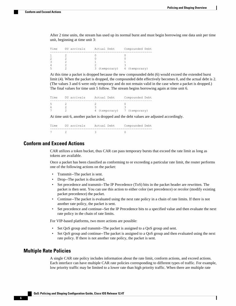
After 2 time units, the stream has used up its normal burst and must begin borrowing one data unit per timeunit, beginning at time unit 3:
Time DU arrivals Actual Debt Compounded Debt-------------------------------------------------------1 2 0 02 2 0 03 2 1 14 2 2 35 2 3 (temporary) 6 (temporary)
At this time a packet is dropped because the new compounded debt (6) would exceed the extended burstlimit (4). When the packet is dropped, the compounded debt effectively becomes 0, and the actual debt is 2.(The values 3 and 6 were only temporary and do not remain valid in the case where a packet is dropped.)The final values for time unit 5 follow. The stream begins borrowing again at time unit 6.
Time DU arrivals Actual Debt Compounded Debt-------------------------------------------------------5 2 2 06 2 3 37 2 4 (temporary) 7 (temporary)
At time unit 6, another packet is dropped and the debt values are adjusted accordingly.
Time DU arrivals Actual Debt Compounded Debt-------------------------------------------------------7 2 3 0
Conform and Exceed ActionsCAR utilizes a token bucket, thus CAR can pass temporary bursts that exceed the rate limit as long astokens are available.
Once a packet has been classified as conforming to or exceeding a particular rate limit, the router performsone of the following actions on the packet:
• Transmit--The packet is sent.• Drop--The packet is discarded.• Set precedence and transmit--The IP Precedence (ToS) bits in the packet header are rewritten. The
packet is then sent. You can use this action to either color (set precedence) or recolor (modify existingpacket precedence) the packet.
• Continue--The packet is evaluated using the next rate policy in a chain of rate limits. If there is notanother rate policy, the packet is sent.
• Set precedence and continue--Set the IP Precedence bits to a specified value and then evaluate the nextrate policy in the chain of rate limits.
For VIP-based platforms, two more actions are possible:
• Set QoS group and transmit--The packet is assigned to a QoS group and sent.• Set QoS group and continue--The packet is assigned to a QoS group and then evaluated using the next
rate policy. If there is not another rate policy, the packet is sent.
Multiple Rate PoliciesA single CAR rate policy includes information about the rate limit, conform actions, and exceed actions.Each interface can have multiple CAR rate policies corresponding to different types of traffic. For example,low priority traffic may be limited to a lower rate than high priority traffic. When there are multiple rate
Policing and Shaping Overview Conform and Exceed Actions
QoS: Policing and Shaping Configuration Guide, Cisco IOS Release 12.4T6

policies, the router examines each policy in the order entered until the packet matches. If no match is found,the default action is to send.
Rate policies can be independent: each rate policy deals with a different type of traffic. Alternatively, ratepolicies can be cascading: a packet may be compared to multiple different rate policies in succession.
Cascading of rate policies allows a series of rate limits to be applied to packets to specify more granularpolicies (for example, you could rate limit total traffic on an access link to a specified subrate bandwidthand then rate limit World Wide Web traffic on the same link to a given proportion of the subrate limit) or tomatch packets against an ordered sequence of policies until an applicable rate limit is encountered (forexample, rate limiting several MAC addresses with different bandwidth allocations at an exchange point).You can configure up to a 100 rate policies on a subinterface.
Restrictions of CAR and VIP-Distributed CARCAR and VIP-distributed CAR can only be used with IP traffic. Non-IP traffic is not rate limited.
CAR or VIP-distributed CAR can be configured on an interface or subinterface. However, CAR and VIP-distributed CAR are not supported on the following interfaces:
• Fast EtherChannel• Tunnel• PRI• Any interface that does not support Cisco Express Forwarding (CEF)
CAR is only supported on ATM subinterfaces with the following encapsulations: aal5snap, aal5mux, andaal5nlpid.
Note CAR provides rate limiting and does not guarantee bandwidth. CAR should be used with other QoSfeatures, such as distributed weighted fair queueing (DWFQ), if premium bandwidth assurances arerequired.
Traffic PolicingTraffic policing allows you to control the maximum rate of traffic sent or received on an interface, and topartition a network into multiple priority levels or class of service (CoS).
The Traffic Policing feature manages the maximum rate of traffic through a token bucket algorithm. Thetoken bucket algorithm can use the user-configured values to determine the maximum rate of trafficallowed on an interface at a given moment in time. The token bucket algorithm is affected by all trafficentering or leaving (depending on where the traffic policy with Traffic Policing configured) and is useful inmanaging network bandwidth in cases where several large packets are sent in the same traffic stream.
The token bucket algorithm provides users with three actions for each packet: a conform action, an exceedaction, and an optional violate action. Traffic entering the interface with Traffic Policing configured isplaced into one of these categories. Within these three categories, users can decide packet treatments. Forinstance, packets that conform can be configured to be transmitted, packets that exceed can be configuredto be sent with a decreased priority, and packets that violate can be configured to be dropped.
Traffic Policing is often configured on interfaces at the edge of a network to limit the rate of traffic enteringor leaving the network. In the most common Traffic Policing configurations, traffic that conforms is
Restrictions of CAR and VIP-Distributed CARTraffic Policing
QoS: Policing and Shaping Configuration Guide, Cisco IOS Release 12.4T 7

transmitted and traffic that exceeds is sent with a decreased priority or is dropped. Users can change theseconfiguration options to suit their network needs.
The Traffic Policing feature supports the following MIBs:
• CISCO-CLASS-BASED-QOS-MIB• CISCO-CLASS-BASED-QOS-CAPABILITY-MIB
This feature also supports RFC 2697, A Single Rate Three Color Marker.
For information on how to configure the Traffic Policing feature, see the "Configuring Traffic Policing"module.
• Benefits of Traffic Policing, page 8
• Restrictions for Traffic Policing, page 8
• Prerequisites for Traffic Policing, page 9
Benefits of Traffic Policing
Bandwidth Management Through Rate Limiting
Traffic policing allows you to control the maximum rate of traffic sent or received on an interface. Trafficpolicing is often configured on interfaces at the edge of a network to limit traffic into or out of the network.Traffic that falls within the rate parameters is sent, whereas traffic that exceeds the parameters is droppedor sent with a different priority.
Packet Marking Through IP Precedence, QoS Group, and DSCP Value Setting
Packet marking allows you to partition your network into multiple priority levels or classes of service(CoS), as follows:
• Use traffic policing to set the IP precedence or differentiated services code point (DSCP) values forpackets entering the network. Networking devices within your network can then use the adjusted IPPrecedence values to determine how the traffic should be treated. For example, the DWRED featureuses the IP Precedence values to determine the probability that a packet will be dropped.
• Use traffic policing to assign packets to a QoS group. The router uses the QoS group to determine howto prioritize packets.
Restrictions for Traffic PolicingThe following restrictions apply to the Traffic Policing feature:
• On a Cisco 7500 series router, traffic policing can monitor CEF switching paths only. In order to usethe Traffic Policing feature, CEF must be configured on both the interface receiving the packet and theinterface sending the packet.
• On a Cisco 7500 series router, traffic policing cannot be applied to packets that originated from or aredestined to a router.
• Traffic policing can be configured on an interface or a subinterface.• Traffic policing is not supported on the following interfaces:
◦ Fast EtherChannel◦ Tunnel◦ PRI
Benefits of Traffic Policing Traffic Policing
QoS: Policing and Shaping Configuration Guide, Cisco IOS Release 12.4T8

◦ Any interface on a Cisco 7500 series router that does not support CEF
Prerequisites for Traffic PolicingOn a Cisco 7500 series router, CEF must be configured on the interface before traffic policing can be used.
Traffic Shaping to Regulate Packet FlowRegulating the packet flow (that is, the flow of traffic) on the network is also known as traffic shaping.Traffic shaping allows you to control the speed of traffic leaving an interface. This way, you can match theflow of the traffic to the speed of the interface receiving the packet.
Cisco provides three mechanisms for regulating or shaping traffic: Class-Based Traffic Shaping, GenericTraffic Shaping (GTS), and Frame Relay Traffic Shaping (FRTS).
For more information about traffic shaping, see the "Regulating Packet Flow Using Traffic Shaping"module.
For information on configuring Frame Relay and FRTS, see the "Configuring Frame Relay" module andthe "MQC-Based Frame Relay Traffic Shaping" module, respectively.
Cisco and the Cisco logo are trademarks or registered trademarks of Cisco and/or its affiliates in the U.S.and other countries. To view a list of Cisco trademarks, go to this URL: www.cisco.com/go/trademarks.Third-party trademarks mentioned are the property of their respective owners. The use of the word partnerdoes not imply a partnership relationship between Cisco and any other company. (1110R)
Any Internet Protocol (IP) addresses and phone numbers used in this document are not intended to beactual addresses and phone numbers. Any examples, command display output, network topology diagrams,and other figures included in the document are shown for illustrative purposes only. Any use of actual IPaddresses or phone numbers in illustrative content is unintentional and coincidental.
Prerequisites for Traffic PolicingTraffic Shaping to Regulate Packet Flow
QoS: Policing and Shaping Configuration Guide, Cisco IOS Release 12.4T 9
Prerequisites for Traffic Policing
QoS: Policing and Shaping Configuration Guide, Cisco IOS Release 12.4T10

Configuring Traffic Policing
This feature module describes the Traffic Policing feature. Traffic policing allows you to control themaximum rate of traffic transmitted or received on an interface.
Use Cisco Feature Navigator to find information about platform support and Cisco IOS and Catalyst OSsoftware image support. To access Cisco Feature Navigator, go to http://www.cisco.com/go/cfn . Anaccount on Cisco.com is not required.
• Finding Feature Information, page 11• Feature Overview, page 11• Supported Platforms, page 13• Supported Standards MIBs and RFCs, page 14• Prerequisites, page 14• Configuration Tasks, page 14• Monitoring and Maintaining Traffic Policing, page 15• Configuration Examples, page 15
Finding Feature InformationYour software release may not support all the features documented in this module. For the latest featureinformation and caveats, see the release notes for your platform and software release. To find informationabout the features documented in this module, and to see a list of the releases in which each feature issupported, see the Feature Information Table at the end of this document.
Use Cisco Feature Navigator to find information about platform support and Cisco software image support.To access Cisco Feature Navigator, go to www.cisco.com/go/cfn. An account on Cisco.com is not required.
Feature OverviewThe Traffic Policing feature performs the following functions:
• Limits the input or output transmission rate of a class of traffic based on user-defined criteria• Marks packets by setting the ATM Cell Loss Priority (CLP) bit, Frame Relay Discard Eligibility (DE)
bit, IP precedence value, IP differentiated services code point (DSCP) value, MPLS experimentalvalue, and Quality of Service (QoS) group.
The Traffic Policing feature is applied when you attach a traffic policy contain the Traffic Policingconfiguration to an interface. A traffic policy is configured using the Modular Quality of Service (QoS)Command-Line Interface (CLI) (MQC).
The table below lists the feature history.
QoS: Policing and Shaping Configuration Guide, Cisco IOS Release 12.4T 11
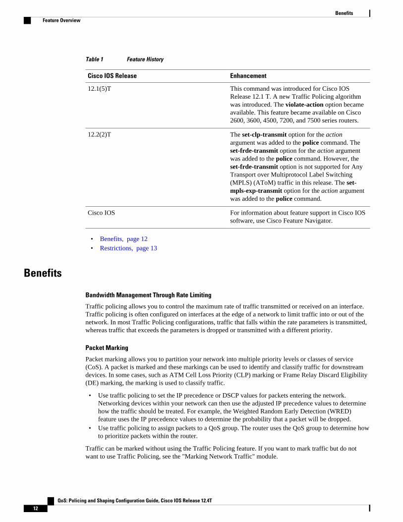
Table 1 Feature History
Cisco IOS Release Enhancement
12.1(5)T This command was introduced for Cisco IOSRelease 12.1 T. A new Traffic Policing algorithmwas introduced. The violate-action option becameavailable. This feature became available on Cisco2600, 3600, 4500, 7200, and 7500 series routers.
12.2(2)T The set-clp-transmit option for the actionargument was added to the police command. Theset-frde-transmit option for the action argumentwas added to the police command. However, theset-frde-transmit option is not supported for AnyTransport over Multiprotocol Label Switching(MPLS) (AToM) traffic in this release. The set-mpls-exp-transmit option for the action argumentwas added to the police command.
Cisco IOS For information about feature support in Cisco IOSsoftware, use Cisco Feature Navigator.
• Benefits, page 12
• Restrictions, page 13
Benefits
Bandwidth Management Through Rate Limiting
Traffic policing allows you to control the maximum rate of traffic transmitted or received on an interface.Traffic policing is often configured on interfaces at the edge of a network to limit traffic into or out of thenetwork. In most Traffic Policing configurations, traffic that falls within the rate parameters is transmitted,whereas traffic that exceeds the parameters is dropped or transmitted with a different priority.
Packet Marking
Packet marking allows you to partition your network into multiple priority levels or classes of service(CoS). A packet is marked and these markings can be used to identify and classify traffic for downstreamdevices. In some cases, such as ATM Cell Loss Priority (CLP) marking or Frame Relay Discard Eligibility(DE) marking, the marking is used to classify traffic.
• Use traffic policing to set the IP precedence or DSCP values for packets entering the network.Networking devices within your network can then use the adjusted IP precedence values to determinehow the traffic should be treated. For example, the Weighted Random Early Detection (WRED)feature uses the IP precedence values to determine the probability that a packet will be dropped.
• Use traffic policing to assign packets to a QoS group. The router uses the QoS group to determine howto prioritize packets within the router.
Traffic can be marked without using the Traffic Policing feature. If you want to mark traffic but do notwant to use Traffic Policing, see the "Marking Network Traffic" module.
Benefits Feature Overview
QoS: Policing and Shaping Configuration Guide, Cisco IOS Release 12.4T12

Packet Prioritization for Frame Relay Frames
The Traffic Policing feature allows users to mark the Frame Relay DE bit of the Frame Relay frame. TheFrame Relay DE bit is one bit and, therefore, can be set to either 0 or 1. In congested environments, frameswith the DE bit set to 1 are discarded before frames with the DE bit set to 0.
Packet Prioritization for ATM Cells
The Traffic Policing feature allows users to mark the ATM CLP bit in ATM cells. The ATM CLP bit isused to prioritize packets in ATM networks. The ATM CLP bit is one bit and, therefore, can be set to either0 or 1. In congested environments, cells with the ATM CLP bit set to 1 are discarded before cells with theATM CLP bit set to 0.
Restrictions• On a Cisco 7500 series router, traffic policing can monitor Cisco Express Forwarding (CEF) switching
paths only. In order to use the Traffic Policing feature, Cisco Express Forwarding must be configuredon both the interface receiving the packet and the interface sending the packet.
• On a Cisco 7500 series router, traffic policing cannot be applied to packets that originated from or aredestined to a router.
• Traffic policing can be configured on an interface or a subinterface.• Traffic policing is not supported on the following interfaces:
◦ Fast EtherChannel◦ Tunnel
Note Traffic policing is supported on tunnels that are using the Cisco generic routing encapsulation (GRE)tunneling protocol.
• ◦ PRI◦ Any interface on a Cisco 7500 series router that does not support Cisco Express Forwarding
Supported Platforms• Cisco 2500 series
Note Cisco IOS Release 12.2(2)T or later does not run on Cisco 2500 series routers.
• Cisco 2600 series• Cisco 3640 routers• Cisco 4500 series• Cisco 7000 series with RSP7000• Cisco 7100 series• Cisco 7200 series• Cisco 7500 series
RestrictionsSupported Platforms
QoS: Policing and Shaping Configuration Guide, Cisco IOS Release 12.4T 13

Note To use the set-clp-transmit action available with this feature, the Enhanced ATM Port Adapter (PA-A3) isrequired. Therefore, the set-clp-transmitaction is not supported on any platform that does not support thePA-A3 adapter (such as the Cisco 2600 series router, the Cisco 3640 router, and the 4500 series router). Formore information, see the documentation for your specific router.
Supported Standards MIBs and RFCsStandards
No new or modified standards are supported by this feature.
MIBs
Class-Based Quality of Service MIB
• CISCO-CLASS-BASED-QOS-MIB• CISCO-CLASS-BASED-QOS-CAPABILITY-MIB
For descriptions of supported MIBs and how to use MIBs, see the Cisco MIB web site on CCO at http://www.cisco.com/public/sw-center/netmgmt/cmtk/mibs.shtml.
RFCs
• RFC 2697, A Single Rate Three Color Marker
PrerequisitesOn a Cisco 7500 series router, Cisco Express Forwarding (CEF) must be configured on the interface beforetraffic policing can be used.
Configuration Tasks• Configuring Traffic Policing, page 15
• Troubleshooting Tips, page 15
Configuring Traffic Policing Supported Standards MIBs and RFCs
QoS: Policing and Shaping Configuration Guide, Cisco IOS Release 12.4T14

Configuring Traffic PolicingCommand Purpose
Router(config-pmap-c)# police bps burst-normalburst-max conform-action action exceed-actionaction violate-action action
Specifies a maximum bandwidth usage by a trafficclass.
Note The Traffic Policing feature works with atoken bucket mechanism. There arecurrently two types of token bucketalgorithms: a single token bucket algorithmand a two token bucket algorithm. A singletoken bucket system is used when theviolate-action option is not specified, and atwo token bucket system is used when theviolate-action option is specified.
Troubleshooting Tips• Check the interface type. Verify that your interface is not mentioned in the nonsupported interface
description in the Restrictions, page 13 section of this module.• For input traffic policing on a Cisco 7500 series router, verify that CEF is configured on the interface
where traffic policing is configured.• For output traffic policing on a Cisco 7500 series router, ensure that the incoming traffic is CEF-
switched. Traffic policing cannot be used on the switching path unless CEF switching is enabled.
Monitoring and Maintaining Traffic PolicingCommand Purpose
Router# show policy-map Displays all configured policy maps.
Router# show policy-map policy-map-name Displays the user-specified policy map.
Router# show policy-map interface Displays statistics and configurations of all inputand output policies that are attached to an interface.
Configuration Examples• Example Configuring a Service Policy that Includes Traffic Policing, page 16
Configuring Traffic PolicingMonitoring and Maintaining Traffic Policing
QoS: Policing and Shaping Configuration Guide, Cisco IOS Release 12.4T 15
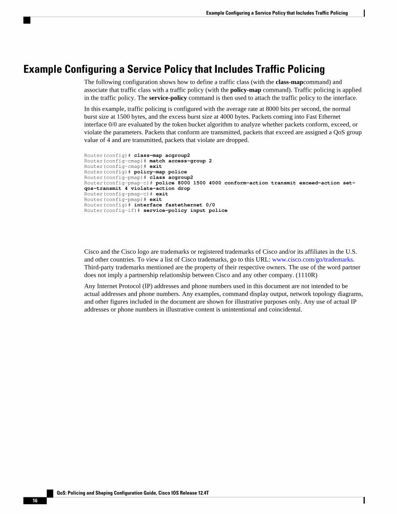
Example Configuring a Service Policy that Includes Traffic PolicingThe following configuration shows how to define a traffic class (with the class-mapcommand) andassociate that traffic class with a traffic policy (with the policy-map command). Traffic policing is appliedin the traffic policy. The service-policy command is then used to attach the traffic policy to the interface.
In this example, traffic policing is configured with the average rate at 8000 bits per second, the normalburst size at 1500 bytes, and the excess burst size at 4000 bytes. Packets coming into Fast Ethernetinterface 0/0 are evaluated by the token bucket algorithm to analyze whether packets conform, exceed, orviolate the parameters. Packets that conform are transmitted, packets that exceed are assigned a QoS groupvalue of 4 and are transmitted, packets that violate are dropped.
Router(config)# class-map acgroup2Router(config-cmap)# match access-group 2Router(config-cmap)# exitRouter(config)# policy-map policeRouter(config-pmap)# class acgroup2Router(config-pmap-c)# police 8000 1500 4000 conform-action transmit exceed-action set-qos-transmit 4 violate-action dropRouter(config-pmap-c)# exitRouter(config-pmap)# exitRouter(config)# interface fastethernet 0/0Router(config-if)# service-policy input police
Cisco and the Cisco logo are trademarks or registered trademarks of Cisco and/or its affiliates in the U.S.and other countries. To view a list of Cisco trademarks, go to this URL: www.cisco.com/go/trademarks.Third-party trademarks mentioned are the property of their respective owners. The use of the word partnerdoes not imply a partnership relationship between Cisco and any other company. (1110R)
Any Internet Protocol (IP) addresses and phone numbers used in this document are not intended to beactual addresses and phone numbers. Any examples, command display output, network topology diagrams,and other figures included in the document are shown for illustrative purposes only. Any use of actual IPaddresses or phone numbers in illustrative content is unintentional and coincidental.
Example Configuring a Service Policy that Includes Traffic Policing
QoS: Policing and Shaping Configuration Guide, Cisco IOS Release 12.4T16

Two-Rate Policer
This document describes the Two-Rate Policer feature and how to configure it. Two-Rate Policer allowsyou to manage traffic rates through an interface; it is especially helpful in managing network bandwidthwhere large packets are in the same traffic stream.
• Finding Feature Information, page 17• Prerequisites for Two-Rate Policer, page 17• Restrictions for Two-Rate Policer, page 18• Information About Two-Rate Policer, page 18• How to Use the Two-Rate Policer, page 20• Configuration Examples, page 21• Additional References, page 22• Feature Information for Two-Rate Policer, page 23
Finding Feature InformationYour software release may not support all the features documented in this module. For the latest featureinformation and caveats, see the release notes for your platform and software release. To find informationabout the features documented in this module, and to see a list of the releases in which each feature issupported, see the Feature Information Table at the end of this document.
Use Cisco Feature Navigator to find information about platform support and Cisco software image support.To access Cisco Feature Navigator, go to www.cisco.com/go/cfn. An account on Cisco.com is not required.
Prerequisites for Two-Rate PolicerSupported Platforms
• Cisco 2600 series• Cisco 3620• Cisco 3640• Cisco 7100 series• Cisco 7200 series• Cisco 7500 series (VIP-based platform only)
QoS: Policing and Shaping Configuration Guide, Cisco IOS Release 12.4T 17

Note The set-clp-transmit action available with Two-Rate Policer, the Enhanced ATM Port Adapter (PA-A3) isrequired. The set-clp-transmit action is not supported on any platform that does not support the PA-A3adapter (such as the Cisco 2600 series router, the Cisco 3620 router, and the 3640 router). For moreinformation, see the documentation for your specific router.
• On a Cisco 7500 series router, Cisco Express Forwarding or Distributed Cisco Express Forwardingmust be configured on the interface before you can use the Two-Rate Policer.
• A traffic class and a service policy must be created, and the service policy must be attached to aspecified interface. These tasks are performed using the Modular quality of service (QoS) Command-Line Interface (CLI) (MQC). For information on the MQC, see the "Applying QoS Features Using theMQC" module.
Restrictions for Two-Rate PolicerThe following restrictions apply to the Two-Rate Policer feature:
• On a Cisco 7500 series router, traffic policing can monitor Cisco Express Forwarding or DistributedCisco Express Forwarding switching paths only. Cisco Express Forwarding or Distributed CiscoExpress Forwarding must be configured on both the interface receiving the packet and the interfacesending the packet.
• On a Cisco 7500 series router, traffic policing cannot be applied to packets that originated from or aredestined to a router.
• Two-rate policing can be configured on an interface, a subinterface, a Frame Relay data-linkconnection identifier (DLCI), and an ATM permanent virtual circuit (PVC).
• Two-rate policing is not supported on the following interfaces:
◦ Fast EtherChannel◦ PRI◦ Any interface on a Cisco 7500 series router that does not support Cisco Express Forwarding or
Distributed Cisco Express Forwarding
Information About Two-Rate PolicerNetworks police traffic by limiting the input or output transmission rate of a class of traffic based on user-defined criteria. Policing traffic allows you to control the maximum rate of traffic sent or received on aninterface and to partition a network into multiple priority levels or class of service (CoS).
The Two-Rate Policer performs the following functions:
• Limits the input or output transmission rate of a class of traffic based on user-defined criteria.• Marks packets by setting the IP precedence value, IP differentiated services code point (DSCP) value,
Multiprotocol Label Switching (MPLS) experimental value, Quality of Service (QoS) group, ATMCell Loss Priority (CLP) bit, and the Frame Relay Discard Eligibility (DE) bit.
With the Two-Rate Policer, you can enforce traffic policing according to two separate rates--committedinformation rate (CIR) and peak information rate (PIR). You can specify the use of these two rates, alongwith their corresponding values, by using two keywords, cir and pir, of the police command.
The Two-Rate Policer manages the maximum rate of traffic through a token bucket algorithm. The tokenbucket algorithm can use the user-configured values to determine the maximum rate of traffic allowed on
Two-Rate Policer Restrictions for Two-Rate Policer
QoS: Policing and Shaping Configuration Guide, Cisco IOS Release 12.4T18
an interface at a given moment in time. The token bucket algorithm is affected by all traffic entering orleaving the interface (depending on the location of the interface on which the Two-Rate Policer isconfigured) and is useful in managing network bandwidth in cases where several large packets are sent inthe same traffic stream.
The token bucket algorithm provides users with three actions for each packet: a conform action, an exceedaction, and an optional violate action. Traffic coming into the interface with the Two-Rate Policerconfigured is assigned one of these categories. Within these three categories, users can decide packettreatments. For instance, packets that conform can be configured to be sent, packets that exceed can beconfigured to be sent with a decreased priority, and packets that violate can be configured to be dropped.
The Two-Rate Policer is often configured on interfaces at the edge of a network to limit the rate of trafficentering or leaving the network. In the most common configurations, traffic that conforms is sent andtraffic that exceeds is sent with a decreased priority or is dropped. Users can change these configurationoptions to suit their network needs.
Note Two-Rate Policer enables you to use Differentiated Services (DiffServ) Assured Forwarding (AF) Per-HopBehavior (PHB) traffic conditioning. For more information about DiffServ, see the "Implementing DiffServfor End-to-End Quality of Service Overview" module.
Note Starting with Cisco IOS Release 12.1(5)T, you can police traffic by using the Traffic Policing feature(sometimes referred to as the single-rate policer). The Two-Rate Policer (available with Cisco IOS Release12.2(4)T) is in addition to the Traffic Policing feature, and it provides additional functionality. For moreinformation about the Traffic Policing feature, see the "Traffic Policing" module.
• Benefits, page 19
Benefits
Bandwidth Management Through Rate Limiting
Two-Rate Policer provides improved bandwidth management through rate limiting. Before this feature wasavailable, you could police traffic with the single-rate Traffic Policing feature. The Traffic Policing featureprovided a certain amount of bandwidth management by allowing you to set the peak burst size (be). TheTwo-Rate Policer supports a higher level of bandwidth management and supports a sustained excess rate.With the Two-Rate Policer, you can enforce traffic policing according to two separate rates--CIR and PIR--specified in bits per second (bps).
Packet Marking Through IP Precedence, DSCP Value, MPLS Experimental Value, and the QoS GroupSetting
In addition to rate-limiting, the Two-Rate Policer allows you to independently mark the packet according towhether the packet conforms, exceeds, or violates a specified rate. Packet marking also allows you topartition your network into multiple priority levels or CoSs.
• Use the Two-Rate Policer to set the IP precedence value, the IP DSCP value, or the MPLSexperimental value for packets that enter the network. Then networking devices within your networkcan use this setting to determine how the traffic should be treated. For example, the Weighted Random
BenefitsInformation About Two-Rate Policer
QoS: Policing and Shaping Configuration Guide, Cisco IOS Release 12.4T 19

Early Detection (WRED) feature uses the IP precedence value to determine the probability that apacket will be dropped.
• Use the Two-Rate Policer to assign packets to a QoS group. The router uses the QoS group todetermine how to prioritize packets within the router.
If you want to mark traffic but do not want to use the Two-Rate Policer, see the "Marking Network Traffic"module.
Packet Marking for Frame Relay Frames
The Two-Rate Policer allows users to mark the Frame Relay DE bit of the Frame Relay frame. The FrameRelay DE bit is one bit and, therefore, can be set to either 0 or 1. In congested environments, frames thathave the DE bit set to 1 are discarded before frames that have the DE bit set to 0.
Packet Marking for ATM Cells
The Two-Rate Policer allows users to mark the ATM CLP bit in ATM cells. The ATM CLP bit is used toprioritize packets in ATM networks. The ATM CLP bit is one bit and, therefore, can be set to either 0 or 1.In congested environments, cells that have the ATM CLP bit set to 1 are discarded before cells that havethe ATM CLP bit set to 0.
How to Use the Two-Rate Policer• Configuring the Two-Rate Policer, page 20
• Verifying the Two-Rate Policer Configuration, page 21
• Troubleshooting Tips, page 21
• Monitoring and Maintaining the Two-Rate Policer, page 21
Configuring the Two-Rate PolicerCommand Purpose
Router(config-pmap-c)#
police cir cir [bc conform-burst] pir pir [be peak-burst
Specifies that both the CIR and the PIR are to beused for two-rate traffic policing. The bc and bekeywords and their associated arguments (conform-burst and peak-burst, respectively) are optional.
Specifies the action taken on a packet when youenable an optional action argument.
Note The Two-Rate Policer works by using atoken bucket mechanism. There arecurrently two types of token bucketalgorithms: a single token bucket algorithm(available through the Traffic Policingfeature) and a two token bucket algorithm(available through the Two-Rate Policer).
Configuring the Two-Rate Policer How to Use the Two-Rate Policer
QoS: Policing and Shaping Configuration Guide, Cisco IOS Release 12.4T20

Verifying the Two-Rate Policer ConfigurationCommand Purpose
Router#
show policy-map interface
Displays statistics and configurations of all inputand output policies attached to an interface.
Troubleshooting Tips• Check the interface type. Verify that your interface is not listed as a nonsupported interface in the
Restrictions for Two-Rate Policer, page 18 section of this module.• For input traffic policing on a Cisco 7500 series router, verify that Cisco Express Forwarding or
Distributed Cisco Express Forwarding is configured on the interface on which traffic policing isconfigured.
• For output traffic policing on a Cisco 7500 series router, ensure that the incoming traffic is CiscoExpress Forwarding-switched or Distributed Cisco Express Forwarding-switched. Traffic policingcannot be used on the switching path unless Cisco Express Forwarding or Distributed Cisco ExpressForwarding switching is enabled.
Monitoring and Maintaining the Two-Rate PolicerCommand Purpose
Router#
show policy-map
Displays all configured policy maps.
Router# show policy-map policy-map-nameDisplays the user-specified policy map.
Router#
show policy-map interface
Displays statistics and configurations of all inputand output policies that are attached to an interface.
Configuration Examples• Example Limiting the Traffic Using a Policer Class, page 21
Example Limiting the Traffic Using a Policer ClassIn this example, the Two-Rate Policer is configured on a class to limit traffic to an average committed rateof 500 kbps and a peak rate of 1 Mbps:
Router(config)# class-map policeRouter(config-cmap)# match access-group 101
Verifying the Two-Rate Policer ConfigurationConfiguration Examples
QoS: Policing and Shaping Configuration Guide, Cisco IOS Release 12.4T 21
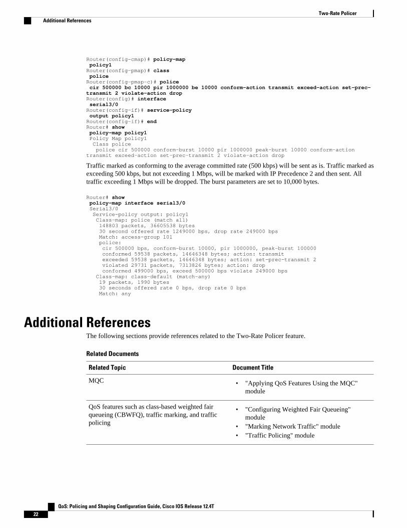
Router(config-cmap)# policy-map policy1Router(config-pmap)# class policeRouter(config-pmap-c)# police cir 500000 bc 10000 pir 1000000 be 10000 conform-action transmit exceed-action set-prec-transmit 2 violate-action dropRouter(config)# interface serial3/0Router(config-if)# service-policy output policy1Router(config-if)# endRouter# show policy-map policy1 Policy Map policy1 Class police police cir 500000 conform-burst 10000 pir 1000000 peak-burst 10000 conform-action transmit exceed-action set-prec-transmit 2 violate-action drop
Traffic marked as conforming to the average committed rate (500 kbps) will be sent as is. Traffic marked asexceeding 500 kbps, but not exceeding 1 Mbps, will be marked with IP Precedence 2 and then sent. Alltraffic exceeding 1 Mbps will be dropped. The burst parameters are set to 10,000 bytes.
Router# show policy-map interface serial3/0 Serial3/0 Service-policy output: policy1 Class-map: police (match all) 148803 packets, 36605538 bytes 30 second offered rate 1249000 bps, drop rate 249000 bps Match: access-group 101 police: cir 500000 bps, conform-burst 10000, pir 1000000, peak-burst 100000 conformed 59538 packets, 14646348 bytes; action: transmit exceeded 59538 packets, 14646348 bytes; action: set-prec-transmit 2 violated 29731 packets, 7313826 bytes; action: drop conformed 499000 bps, exceed 500000 bps violate 249000 bps Class-map: class-default (match-any) 19 packets, 1990 bytes 30 seconds offered rate 0 bps, drop rate 0 bps Match: any
Additional ReferencesThe following sections provide references related to the Two-Rate Policer feature.
Related Documents
Related Topic Document Title
MQC • "Applying QoS Features Using the MQC"module
QoS features such as class-based weighted fairqueueing (CBWFQ), traffic marking, and trafficpolicing
• "Configuring Weighted Fair Queueing"module
• "Marking Network Traffic" module• "Traffic Policing" module
Two-Rate Policer Additional References
QoS: Policing and Shaping Configuration Guide, Cisco IOS Release 12.4T22
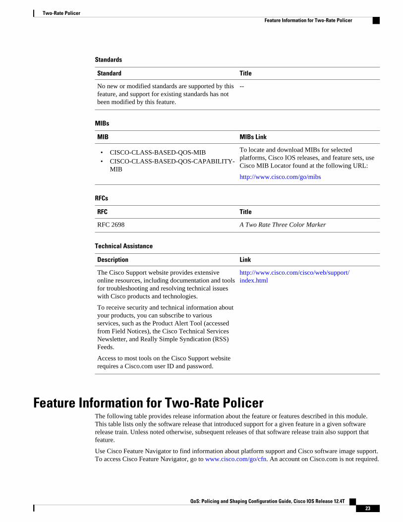
Standards
Standard Title
No new or modified standards are supported by thisfeature, and support for existing standards has notbeen modified by this feature.
--
MIBs
MIB MIBs Link
• CISCO-CLASS-BASED-QOS-MIB• CISCO-CLASS-BASED-QOS-CAPABILITY-
MIB
To locate and download MIBs for selectedplatforms, Cisco IOS releases, and feature sets, useCisco MIB Locator found at the following URL:
http://www.cisco.com/go/mibs
RFCs
RFC Title
RFC 2698 A Two Rate Three Color Marker
Technical Assistance
Description Link
The Cisco Support website provides extensiveonline resources, including documentation and toolsfor troubleshooting and resolving technical issueswith Cisco products and technologies.
To receive security and technical information aboutyour products, you can subscribe to variousservices, such as the Product Alert Tool (accessedfrom Field Notices), the Cisco Technical ServicesNewsletter, and Really Simple Syndication (RSS)Feeds.
Access to most tools on the Cisco Support websiterequires a Cisco.com user ID and password.
http://www.cisco.com/cisco/web/support/index.html
Feature Information for Two-Rate PolicerThe following table provides release information about the feature or features described in this module.This table lists only the software release that introduced support for a given feature in a given softwarerelease train. Unless noted otherwise, subsequent releases of that software release train also support thatfeature.
Use Cisco Feature Navigator to find information about platform support and Cisco software image support.To access Cisco Feature Navigator, go to www.cisco.com/go/cfn. An account on Cisco.com is not required.
Two-Rate PolicerFeature Information for Two-Rate Policer
QoS: Policing and Shaping Configuration Guide, Cisco IOS Release 12.4T 23
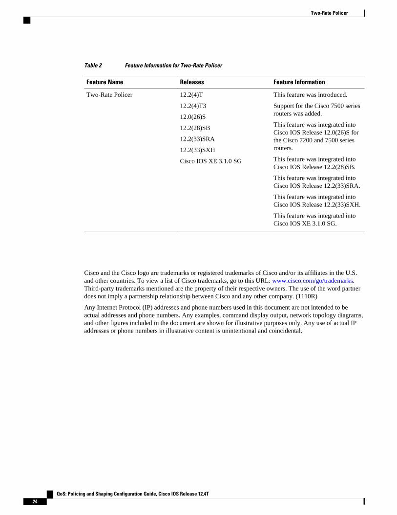
Table 2 Feature Information for Two-Rate Policer
Feature Name Releases Feature Information
Two-Rate Policer 12.2(4)T
12.2(4)T3
12.0(26)S
12.2(28)SB
12.2(33)SRA
12.2(33)SXH
Cisco IOS XE 3.1.0 SG
This feature was introduced.
Support for the Cisco 7500 seriesrouters was added.
This feature was integrated intoCisco IOS Release 12.0(26)S forthe Cisco 7200 and 7500 seriesrouters.
This feature was integrated intoCisco IOS Release 12.2(28)SB.
This feature was integrated intoCisco IOS Release 12.2(33)SRA.
This feature was integrated intoCisco IOS Release 12.2(33)SXH.
This feature was integrated intoCisco IOS XE 3.1.0 SG.
Cisco and the Cisco logo are trademarks or registered trademarks of Cisco and/or its affiliates in the U.S.and other countries. To view a list of Cisco trademarks, go to this URL: www.cisco.com/go/trademarks.Third-party trademarks mentioned are the property of their respective owners. The use of the word partnerdoes not imply a partnership relationship between Cisco and any other company. (1110R)
Any Internet Protocol (IP) addresses and phone numbers used in this document are not intended to beactual addresses and phone numbers. Any examples, command display output, network topology diagrams,and other figures included in the document are shown for illustrative purposes only. Any use of actual IPaddresses or phone numbers in illustrative content is unintentional and coincidental.
Two-Rate Policer
QoS: Policing and Shaping Configuration Guide, Cisco IOS Release 12.4T24

Policer Enhancement - Multiple Actions
Feature History
Release Modification
12.2(8)T This feature was introduced.
This document describes the Policer Enhancement -- Multiple Actions feature in Cisco IOS Release12.2(8)T. It includes the following sections:
• Finding Feature Information, page 25• Feature Overview, page 25• Supported Platforms, page 27• Supported Standards MIBs and RFCs, page 27• Prerequisites, page 28• Configuration Tasks, page 28• Monitoring and Maintaining the Multiple Policer Actions, page 29• Configuration Examples, page 29
Finding Feature InformationYour software release may not support all the features documented in this module. For the latest featureinformation and caveats, see the release notes for your platform and software release. To find informationabout the features documented in this module, and to see a list of the releases in which each feature issupported, see the Feature Information Table at the end of this document.
Use Cisco Feature Navigator to find information about platform support and Cisco software image support.To access Cisco Feature Navigator, go to www.cisco.com/go/cfn. An account on Cisco.com is not required.
Feature OverviewThis feature further extends the functionality of the Cisco IOS Traffic Policing feature (a single-ratepolicer) and the Two-Rate Policer feature. The Traffic Policing and Two-Rate Policer features are trafficpolicing mechanisms that allow you to control the maximum rate of traffic sent or received on an interface.Both of these traffic policing mechanisms mark packets as either conforming to, exceeding, or violating aspecified rate. After a packet is marked, you can specify an action to be taken on the packet based on thatmarking.
QoS: Policing and Shaping Configuration Guide, Cisco IOS Release 12.4T 25

With both the Traffic Policing feature and the Two-Rate Policer feature, you can specify only one conformaction, one exceed action, and one violate action. Now with the new Policer Enhancement -- MultipleActions feature, you can specify multiple conform, exceed, and violate actions for the marked packets.
• Benefits, page 26
• Restrictions, page 26
• Related Features and Technologies, page 26
• Related Documents, page 26
BenefitsBefore this feature, you could specify only one marking action for a packet, in addition to transmitting thepacket. This feature provides enhanced flexibility by allowing you to specify multiple marking actions for apacket, as required. For example, if you know the packet will be transmitted through both a TCP/IP and aFrame Relay environment, you can change the DSCP value of the exceeding or violating packet, and alsoset the Frame Relay Discard Eligibility (DE) bit from 0 to 1 to indicate lower priority.
Restrictions• On a Cisco 7500 series router, traffic policing can monitor Cisco Express Forwarding (CEF) or
distributed CEF (dCEF) switching paths only. To use the Two-Rate Policer, CEF or dCEF must beconfigured on both the interface receiving the packet and the interface sending the packet.
• On a Cisco 7500 series router, traffic policing cannot be applied to packets that originated from or aredestined to a router.
• Multiple policer actions can be configured on an interface, a subinterface, a Frame Relay data-linkconnection identifier (DLCI), and an ATM permanent virtual circuit (PVC) only.
• When using this feature, you can specify a maximum of four actions at one time.• Multiple policer actions are not supported on the following interfaces:
◦ Fast EtherChannel◦ PRI◦ Any interface on a Cisco 7500 series router that does not support CEF or dCEF
Related Features and Technologies• Modular Quality of Service (QoS) Command-Line Interface (CLI) (MQC)• Class-Based Weighted Fair Queueing (CBWFQ)• Class-Based Packet Marking• Traffic Policing• Two-Rate Policing
Related Documents• "Applying QoS Features Using the MQC" module• "Configuring Weighted Fair Queueing" module• Marking Network Traffic" module• "Policing and Shaping Overview" module
Benefits Feature Overview
QoS: Policing and Shaping Configuration Guide, Cisco IOS Release 12.4T26
• "Traffic Policing" module• "Two-Rate Policer" module• Cisco IOS Quality of Service Solutions Command Reference.• RFC 2697, A Single Rate Three Color Marker• RFC 2698, A Two Rate Three Color Marker
Supported Platforms• Cisco 1700 series• Cisco 2600 series• Cisco 3620• Cisco 3640• Cisco 3660• Cisco 7100 series• Cisco 7200 series• Cisco 7500 series (VIP-based platform only)• Cisco MC3810
Note To use the set-clp-transmitaction available with this feature, the Enhanced ATM Port Adapter (PA-A3) isrequired. Therefore, the set-clp-transmit action is not supported on any platform that does not support thePA-A3 adapter (such as the Cisco 2600 series router and the Cisco 3640 router). For more information,refer to the documentation for your specific router.
Supported Standards MIBs and RFCsStandards
No new or modified standards are supported by this feature.
MIBs
• CISCO-CLASS-BASED-QOS-MIB• CISCO-CLASS-BASED-QOS-CAPABILITY-MIB
To obtain lists of supported MIBs by platform and Cisco IOS release, and to download MIB modules, go tothe Cisco MIB website on Cisco.com at the following URL:
http://www.cisco.com/public/sw-center/netmgmt/cmtk/mibs.shtml
RFCs
• RFC 2697, A Single Rate Three Color Marker• RFC 2698, A Two Rate Three Color Marker
Policer Enhancement - Multiple ActionsSupported Platforms
QoS: Policing and Shaping Configuration Guide, Cisco IOS Release 12.4T 27

Prerequisites• On a Cisco 7500 series router, CEF or dCEF must be configured on the interface before you can use
the Policer Enhancement -- Multiple Actions feature.• To configure the Policer Enhancement -- Multiple Actions feature, a traffic class and a service policy
must be created, and the service policy must be attached to a specified interface.
Configuration Tasks• Configuring Multiple Policer Actions, page 28
• Verifying the Multiple Policer Actions Configuration, page 28
• Troubleshooting Tips, page 29
Configuring Multiple Policer Actions
SUMMARY STEPS
1. Router(config)# policy-map policy-map-name
2. Router(config-pmap)# class class-default
3. Router(config-pmap-c)# police {cir cir}[bc conform-burst]{pir pir} [be peak-burst] [conform-actionaction [exceed-action action [violate-action action]]]
DETAILED STEPS
Command or Action Purpose
Step 1 Router(config)# policy-map policy-map-name Creates a policy map. Enters policy-map configuration mode.
Step 2 Router(config-pmap)# class class-default Specifies the default traffic class for a service policy. Enters policy-map class configuration mode.
Step 3 Router(config-pmap-c)# police {cir cir}[bc conform-burst]{pir pir} [be peak-burst][conform-action action [exceed-action action[violate-action action]]]
Configures traffic policing and specifies multiple actions applied topackets marked as conforming to, exceeding, or violating a specificrate. Use one line per action that you want to specify. Enters policy-map class police configuration mode.
Verifying the Multiple Policer Actions ConfigurationCommand Purpose
Router#
show policy-map interface
Displays statistics and configurations of all inputand output policies attached to an interface.
Configuring Multiple Policer Actions Prerequisites
QoS: Policing and Shaping Configuration Guide, Cisco IOS Release 12.4T28

Troubleshooting Tips• Check the interface type. Verify that your interface is not listed as a nonsupported interface in the
"Restrictions" section of this document.• For input traffic policing on a Cisco 7500 series router, verify that CEF or dCEF is configured on the
interface on which traffic policing is configured.• For output traffic policing on a Cisco 7500 series router, ensure that the incoming traffic is CEF-
switched or dCEF-switched. Traffic policing cannot be used on the switching path unless CEF ordCEF switching is enabled.
Monitoring and Maintaining the Multiple Policer ActionsCommand Purpose
Router# show policy-mapDisplays all configured policy maps.
Router# show policy-map policy-map-nameDisplays the user-specified policy map.
Router# show policy-map interfaceDisplays statistics and configurations of all inputand output policies that are attached to an interface.
Configuration Examples• Example Multiple Actions in a Two-Rate Policer, page 29
• Example Verifying the Multiple Policer Actions, page 30
Example Multiple Actions in a Two-Rate PolicerIn the following example, a policy map called police is configured to use a two-rate policer to police trafficleaving an interface. Two rates, a committed information rate (CIR) of 1 Mbps and a peak information rate(PIR) of 2 Mbps, have been specified.
Router(config)# policy-map policeRouter(config-pmap)# class class-defaultRouter(config-pmap-c)# police cir 1000000 pir 2000000 Router(config-pmap-c-police)# conform-action transmitRouter(config-pmap-c-police)# exceed-action set-prec-transmit 4Router(config-pmap-c-police)# exceed-action set-frdeRouter(config-pmap-c-police)# violate-action set-prec-transmit 2Router(config-pmap-c-police)# violate-action set-frde-transmit Router(config-pmap-c-police)# end
The following actions will be performed on packets associated with the policy map called police:
• All packets marked as conforming to these rates (that is, packets conforming to the CIR) will betransmitted unaltered.
Troubleshooting TipsMonitoring and Maintaining the Multiple Policer Actions
QoS: Policing and Shaping Configuration Guide, Cisco IOS Release 12.4T 29
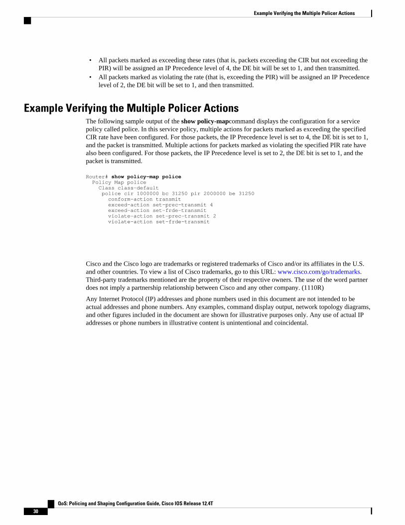
• All packets marked as exceeding these rates (that is, packets exceeding the CIR but not exceeding thePIR) will be assigned an IP Precedence level of 4, the DE bit will be set to 1, and then transmitted.
• All packets marked as violating the rate (that is, exceeding the PIR) will be assigned an IP Precedencelevel of 2, the DE bit will be set to 1, and then transmitted.
Example Verifying the Multiple Policer ActionsThe following sample output of the show policy-mapcommand displays the configuration for a servicepolicy called police. In this service policy, multiple actions for packets marked as exceeding the specifiedCIR rate have been configured. For those packets, the IP Precedence level is set to 4, the DE bit is set to 1,and the packet is transmitted. Multiple actions for packets marked as violating the specified PIR rate havealso been configured. For those packets, the IP Precedence level is set to 2, the DE bit is set to 1, and thepacket is transmitted.
Router# show policy-map police Policy Map police Class class-default police cir 1000000 bc 31250 pir 2000000 be 31250 conform-action transmit exceed-action set-prec-transmit 4 exceed-action set-frde-transmit violate-action set-prec-transmit 2 violate-action set-frde-transmit
Cisco and the Cisco logo are trademarks or registered trademarks of Cisco and/or its affiliates in the U.S.and other countries. To view a list of Cisco trademarks, go to this URL: www.cisco.com/go/trademarks.Third-party trademarks mentioned are the property of their respective owners. The use of the word partnerdoes not imply a partnership relationship between Cisco and any other company. (1110R)
Any Internet Protocol (IP) addresses and phone numbers used in this document are not intended to beactual addresses and phone numbers. Any examples, command display output, network topology diagrams,and other figures included in the document are shown for illustrative purposes only. Any use of actual IPaddresses or phone numbers in illustrative content is unintentional and coincidental.
Example Verifying the Multiple Policer Actions
QoS: Policing and Shaping Configuration Guide, Cisco IOS Release 12.4T30

Percentage-Based Policing and Shaping
Feature History
Release Modification
12.2(13)T This feature was introduced.
Supported Platforms
For platforms supported in Cisco IOS Release12.2(13)T, consult Cisco Feature Navigator.
This document describes the Percentage-Based Policing and Shaping feature in Cisco IOS Release12.2(13)T. It includes the following sections:
• Finding Feature Information, page 31• Feature Overview, page 31• Supported Standards MIBs and RFCs, page 33• Prerequisites, page 33• Configuration Tasks, page 34• Configuration Examples, page 35
Finding Feature InformationYour software release may not support all the features documented in this module. For the latest featureinformation and caveats, see the release notes for your platform and software release. To find informationabout the features documented in this module, and to see a list of the releases in which each feature issupported, see the Feature Information Table at the end of this document.
Use Cisco Feature Navigator to find information about platform support and Cisco software image support.To access Cisco Feature Navigator, go to www.cisco.com/go/cfn. An account on Cisco.com is not required.
Feature OverviewCisco IOS quality of service (QoS) offers two kinds of traffic regulation mechanisms--traffic policing andtraffic shaping. A traffic policer typically drops traffic that violates a specific rate. A traffic shaper typicallydelays excess traffic using a buffer to hold packets and shapes the flow when the data rate to a queue ishigher than expected.
QoS: Policing and Shaping Configuration Guide, Cisco IOS Release 12.4T 31

Traffic shaping and traffic policing can work in tandem and can be configured in a class map. Class mapsorganize data packets into specific categories ("classes") that can, in turn, receive a user-defined QoStreatment when used in policy maps (sometimes referred to as "service policies").
Before this feature, traffic policing and traffic shaping were configured on the basis of a user-specifiedamount of bandwidth available on the interface. Policy maps were then configured on the basis of thatspecific amount of bandwidth, meaning that separate policy maps were required for each interface.
This feature provides the ability to configure traffic policing and traffic shaping based on a percentage ofbandwidth available on the interface. Configuring traffic policing and traffic shaping in this manner enablescustomers to use the same policy map for multiple interfaces with differing amounts of bandwidth.
This feature also provides the option of specifying burst sizes in milliseconds (ms) when configuring trafficpolicing and shaping based on a percentage of bandwidth.
• Benefits, page 32
• Restrictions, page 32
• Related Features and Technologies, page 32
• Related Documents, page 32
Benefits
Increased Flexibility
This feature provides the ability to configure traffic policing and traffic shaping based on a percentage ofbandwidth available on an interface. Configuring traffic policing and traffic shaping in this manner enablescustomers to use the same policy map for multiple interfaces with differing amounts of bandwidth.
RestrictionsThe shape (percent) command, when used in "child" (nested) policy maps, is not supported on the Cisco7500, the Cisco 7200, or lower series routers. Therefore, the shape (percent) command cannot beconfigured for use in nested policy maps on these routers.
Related Features and Technologies• Modular QoS command-line interface (CLI) (Modular QoS CLI)• Class-based weighted fair queueing (CBWFQ)• Class-based packet marking• Cisco Express Forwarding (CEF) and Distributed CEF (dCEF)• Traffic policing• Two-rate policing• Traffic shaping
Related Documents• "Applying QoS Features Using the MQC" module• "Configuring Weighted Fair Queueing" module• "Marking Network Traffic" module
Benefits Feature Overview
QoS: Policing and Shaping Configuration Guide, Cisco IOS Release 12.4T32
• "Policing and Shaping Overview" module• "Traffic Policing" module• "Two-Rate Policer" module• "Policer Enhancements-Multiple Actions" module• "Cisco Express Forwarding Overview" module• Cisco IOS Quality of Service Solutions Command Reference• Cisco IOS Switching Services Command Reference• RFC 2697, A Single Rate Three Color Marker• RFC 2698, A Two Rate Three Color Marker
Supported Standards MIBs and RFCsStandards
None
MIBs
None
To locate and download MIBs for selected platforms, Cisco IOS releases, and feature sets, use Cisco MIBLocator found at the following URL:
http://tools.cisco.com/ITDIT/MIBS/servlet/index
If Cisco MIB Locator does not support the MIB information that you need, you can also obtain a list ofsupported MIBs and download MIBs from the Cisco MIBs page at the following URL:
http://www.cisco.com/public/sw-center/netmgmt/cmtk/mibs.shtml
To access Cisco MIB Locator, you must have an account on Cisco.com. If you have forgotten or lost youraccount information, send a blank e-mail to [email protected]. An automatic check will verify thatyour e-mail address is registered with Cisco.com. If the check is successful, account details with a newrandom password will be e-mailed to you. Qualified users can establish an account on Cisco.com byfollowing the directions found at this URL:
http://www.cisco.com/register
RFCs
• RFC 2697, A Single Rate Three Color Marker• RFC 2698, A Two Rate Three Color Marker
PrerequisitesOn a Cisco 7500 series router, Distributed Cisco Express Forwarding (dCEF) must be configured on theinterface before you can use the Percentage-Based Policing and Shaping feature.
Percentage-Based Policing and ShapingSupported Standards MIBs and RFCs
QoS: Policing and Shaping Configuration Guide, Cisco IOS Release 12.4T 33

Configuration Tasks• Configuring Policing and Shaping Based on Bandwidth Percentage, page 34
• Attaching the Policy Map to an Interface or a VC, page 35
• Verifying the Policing and Shaping Bandwidth Percentage Setting, page 35
• Troubleshooting Tips, page 35
Configuring Policing and Shaping Based on Bandwidth Percentage
SUMMARY STEPS
1. Router (config)# policy-mappolicy-name
2. Router(config-pmap)# class-mapclass-map-name
3. Router(config-pmap-c)# police cir percent percent[bcconform-burst-in-msec ] [ pir percent percent ][bepeak-burst-in-msec ]
4. Router(config-pmap-c)# shape {average | peak} percentpercent [bc ] [be ]
5. Router (config-pmap-c)# service-policypolicy-map-name
6. Router(config-pmap-c)# exit
DETAILED STEPS
Command or Action Purpose
Step 1 Router (config)# policy-mappolicy-name Specifies the name of the policy map to be created. Enters policy-map configuration mode.
Step 2 Router(config-pmap)# class-mapclass-map-name Specifies the name of the class map to be created. Enters policy-map class configuration mode.
Step 3 Router(config-pmap-c)# police cir percent percent[bcconform-burst-in-msec ] [ pir percent percent ] [bepeak-burst-in-msec ]
Configures traffic policing.
Step 4 Router(config-pmap-c)# shape {average | peak}percentpercent [bc ] [be ]
Configures traffic shaping using either an average or peak trafficshaping rate based on a percentage of available bandwidth.
Step 5 Router (config-pmap-c)# service-policypolicy-map-name
Specifies the name of a policy map to be used as a child policy mapfor this class.
Step 6 Router(config-pmap-c)# exit Exits policy-map class configuration mode.
Configuring Policing and Shaping Based on Bandwidth Percentage Configuration Tasks
QoS: Policing and Shaping Configuration Guide, Cisco IOS Release 12.4T34
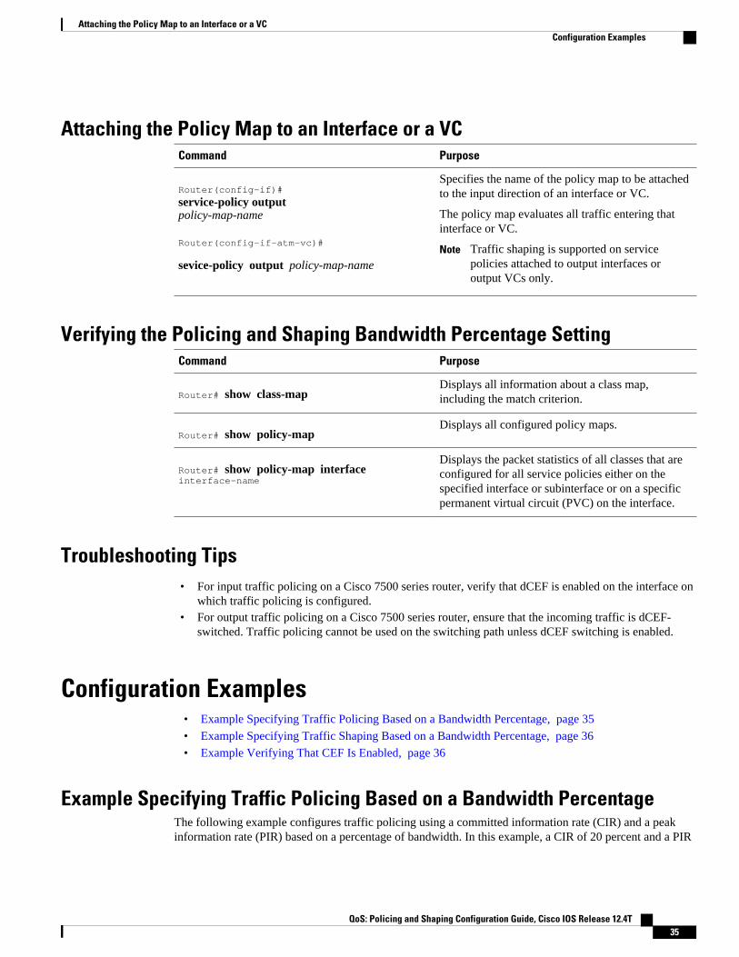
Attaching the Policy Map to an Interface or a VCCommand Purpose
Router(config-if)#
service-policy outputpolicy-map-name
Router(config-if-atm-vc)#
sevice-policy output policy-map-name
Specifies the name of the policy map to be attachedto the input direction of an interface or VC.
The policy map evaluates all traffic entering thatinterface or VC.
Note Traffic shaping is supported on servicepolicies attached to output interfaces oroutput VCs only.
Verifying the Policing and Shaping Bandwidth Percentage SettingCommand Purpose
Router# show class-mapDisplays all information about a class map,including the match criterion.
Router# show policy-map Displays all configured policy maps.
Router# show policy-map interface interface-name
Displays the packet statistics of all classes that areconfigured for all service policies either on thespecified interface or subinterface or on a specificpermanent virtual circuit (PVC) on the interface.
Troubleshooting Tips• For input traffic policing on a Cisco 7500 series router, verify that dCEF is enabled on the interface on
which traffic policing is configured.• For output traffic policing on a Cisco 7500 series router, ensure that the incoming traffic is dCEF-
switched. Traffic policing cannot be used on the switching path unless dCEF switching is enabled.
Configuration Examples• Example Specifying Traffic Policing Based on a Bandwidth Percentage, page 35
• Example Specifying Traffic Shaping Based on a Bandwidth Percentage, page 36
• Example Verifying That CEF Is Enabled, page 36
Example Specifying Traffic Policing Based on a Bandwidth PercentageThe following example configures traffic policing using a committed information rate (CIR) and a peakinformation rate (PIR) based on a percentage of bandwidth. In this example, a CIR of 20 percent and a PIR
Attaching the Policy Map to an Interface or a VCConfiguration Examples
QoS: Policing and Shaping Configuration Guide, Cisco IOS Release 12.4T 35

of 40 percent have been specified. Additionally, an optional bc value and be value (300 ms and 400 ms,respectively) have been specified.
Router (config)#
policy-map policy1
Router(config-pmap)# class-map class1
Router(config-pmap-c)# police cir percent 20 bc 300 ms pir percent 40 be 400 ms
Router (config-pmap-c)# service-policy child-policy1
Router(config-pmap-c)# exit
Router(config-pmap-c)# interface serial 3/1
Router(config-if)#
service-policy output policy1
The purpose of the burst parameters (bc and be values) is to drop packets gradually, as is done withWeighted Random Early Detection (WRED), and to avoid tail drop. Setting sufficiently high burst valueshelps to ensure good throughput.
Example Specifying Traffic Shaping Based on a Bandwidth PercentageThe following example configures traffic shaping using an average shaping rate based on a percentage ofbandwidth. In this example, 25 percent of the bandwidth has been specified. Additionally, an optional bcvalue and be value (300 ms and 400 ms, respectively) have been specified.
Router (config)#
policy-map policy1
Router(config-pmap)# class-map class1
Router(config-pmap-c)# shape average percent 25 300 ms 400 ms
Router (config-pmap-c)# service-policy child-policy1
Router(config-pmap-c)# exit
Router(config-pmap-c)# interface serial 3/1
Router(config-if)#
service-policy output policy1
The purpose of the bc and be values is to drop packets gradually, as is done with WRED, and to avoid taildrop. Setting sufficiently high burst values helps to ensure good throughput.
Example Verifying That CEF Is EnabledOn a Cisco 7500 series router, dCEF must be configured on the interface before you can use thePercentage-Based Policing and Shaping feature. The show ip cef summary command can be used to
Example Specifying Traffic Shaping Based on a Bandwidth Percentage Configuration Examples
QoS: Policing and Shaping Configuration Guide, Cisco IOS Release 12.4T36

confirm that dCEF is enabled and is being used for IP switching. In rare instances, this command displays"IP Distributed CEF without switching" in the command output. This indicates that dCEF is disabled. Thefollowing sample output of the show ip cef summary command indicates that dCEF is disabled:
Router# show ip cef summary IP Distributed CEF with switching (Table Version 36), flags=0x0 18 routes, 0 reresolve, 0 unresolved (0 old, 0 new), peak 3 18 leaves, 19 nodes, 22136 bytes, 45 inserts, 27 invalidations 0 load sharing elements, 0 bytes, 0 references universal per-destination load sharing algorithm, id 680E93E2 3(0) CEF resets, 1 revisions of existing leaves Resolution Timer:Exponential (currently 1s, peak 1s) 0 in-place/0 aborted modifications refcounts: 5136 leaf, 5120 node
When you configure a feature that requires special handling or is not yet supported in the dCEF switchingpaths, packets are forwarded to the next switching layer for handling. In this instance, the output of theshow cef interface command displays "Packets switched to this interface on line card are dropped to nextslow path" as shown in the following sample output.
Router# show cef interface Serial 10/0/0:28 Serial10/0/0:28 is up (if_number 38) Internet address is 90.0.0.1/8 ICMP redirects are never sent Per packet loadbalancing is disabled Inbound access list is not set Interface is marked as point to point interface Packets switched to this interface on linecard are dropped to next slow path Hardware idb is Serial10/0/0:28 Fast switching type 4, interface type 20 IP Distributed CEF switching enabled Fast flags 0x0. ifindex 37(37) Slot 10 Slot unit 0 VC 28 Hardware transmit queue ptr 0x48001AE0 (0x48001AE0) Transmit limit accumulator 0x48000102 (0x48000102) IP MTU 1500
Cisco and the Cisco logo are trademarks or registered trademarks of Cisco and/or its affiliates in the U.S.and other countries. To view a list of Cisco trademarks, go to this URL: www.cisco.com/go/trademarks.Third-party trademarks mentioned are the property of their respective owners. The use of the word partnerdoes not imply a partnership relationship between Cisco and any other company. (1110R)
Any Internet Protocol (IP) addresses and phone numbers used in this document are not intended to beactual addresses and phone numbers. Any examples, command display output, network topology diagrams,and other figures included in the document are shown for illustrative purposes only. Any use of actual IPaddresses or phone numbers in illustrative content is unintentional and coincidental.
Percentage-Based Policing and Shaping
QoS: Policing and Shaping Configuration Guide, Cisco IOS Release 12.4T 37

Example Verifying That CEF Is Enabled
QoS: Policing and Shaping Configuration Guide, Cisco IOS Release 12.4T38

Modular QoS CLI Three-Level HierarchicalPolicer
The Modular QoS CLI (MQC) Three-Level Hierarchical Policer extends the traffic policing functionalityby allowing you to configure traffic policing at three levels of policy map hierarchies; a primary level, asecondary level, and a tertiary level. Traffic policing may be configured at any or all of these levels,depending on the needs of your network. Configuring traffic policing in a three-level hierarchical structureprovides a high degree of granularity for traffic policing.
Feature Specifications for the Modular QoS CLI (MQC) Three-Level Hierarchical Policer
Feature History
Release Modification
12.2(13)T This feature was introduced.
Supported Platforms
For platforms supported in Cisco IOS Release12.2(13)T, consult Cisco Feature Navigator.
• Finding Feature Information, page 39• Restrictions for the Modular QoS CLI Three-Level Hierarchical Policer, page 40• Information About the Modular QoS CLI Three-Level Hierarchical Policer, page 41• How to Configure the Modular QoS CLI Three-Level Hierarchical Policer, page 43• Configuration Examples for the Modular QoS CLI Three-Level Hierarchical Policer, page 48• Additional References, page 50
Finding Feature InformationYour software release may not support all the features documented in this module. For the latest featureinformation and caveats, see the release notes for your platform and software release. To find informationabout the features documented in this module, and to see a list of the releases in which each feature issupported, see the Feature Information Table at the end of this document.
Use Cisco Feature Navigator to find information about platform support and Cisco software image support.To access Cisco Feature Navigator, go to www.cisco.com/go/cfn. An account on Cisco.com is not required.
QoS: Policing and Shaping Configuration Guide, Cisco IOS Release 12.4T 39

Restrictions for the Modular QoS CLI Three-LevelHierarchical Policer
If traffic policing is configured at both the top level and secondary levels, note the following caveats:
• When traffic policing is configured at both the primary and secondary levels, the traffic policer at thesecondary level acts only on packets sent by the policer at the top level.
However, the packet classification for the policy map at the secondary level occurs before the primary levelpolicer has acted on the classes. When this situation occurs, the class counters for the policy map at thesecondary level may not be equal to the number of packets acted upon by the second level policer.
The following output of the show policy-map interfacecommand helps to illustrate this point. In thissample output two policy maps (called "primary_level," and "secondary_level," respectively) have beenconfigured. The primary_level policy map contains a class map called "c1," and the secondary_level policymap contains a class map called "c3".
> > > show policy interface serial5/0.1> > > Serial5/0.1> > >> > > Service-policy output: primary_level> > >> > > Class-map: c1 (match-all)> > > 24038 packets, 3004750 bytes> > > 30 second offered rate 0 bps, drop rate 0 bps> > > Match: any> > > police:> > > cir 300000 bps, bc 9375 bytes> > > conformed 18105 packets, 2263125 bytes; actions:> > > transmit> > > exceeded 5933 packets, 741625 bytes; actions: (*)> > > drop> > > conformed 0 bps, exceed 0 bps> > >> > > Service-policy : secondary_level> > >> > > Class-map: c3 (match-all)> > > 24038 packets, 3004750 bytes > > > 30 second offered rate 0 bps, drop rate 0 bps> > > Match: any> > > police: (<= Indicates traffic policing has been configured)> > > cir 200000 bps, bc 3000 bytes> > > pir 250000 bps, be 3000 bytes> > > conformed 12047 packets, 1505875 bytes; actions: (**)> > > set-frde-transmit> > > exceeded 3004 packets, 375500 bytes; actions: (**)> > > set-frde-transmit> > > violated 3054 packets, 381750 bytes; actions: (**)> > > set-frde-transmit> > > conformed 0 bps, exceed 0 bps, violate 0 bps> > >> > > Class-map: class-default (match-any)> > > 0 packets, 0 bytes> > > 30 second offered rate 0 bps, drop rate 0 bps> > > Match: any> > > 0 packets, 0 bytes> > > 30 second rate 0 bps
Note the following about this example:
• ◦ The class counter for the class map called "c3" shows 24038 packets (italicized in the example).◦ Traffic policing has been configured in the policy map, and the traffic policing feature for class
map "c3" shows a total of 18105 packets -- 12047 conformed packets, plus 3004 exceeded
Modular QoS CLI Three-Level Hierarchical Policer Restrictions for the Modular QoS CLI Three-Level Hierarchical Policer
QoS: Policing and Shaping Configuration Guide, Cisco IOS Release 12.4T40
packets, plus 3054 violated packets (indicated by the double asterisks ("**") in the example). Thistotal is because 5933 packets have already been dropped in class map "c1" (indicated by the "*"in the example).
◦ Therefore, only 18105 packets (24038 packets minus 5933 packets) are acted upon by the trafficpolicing feature configured in the second_level policy map.
• In this implementation of the Modular QoS CLI (MQC) Three-Level Hierarchical Policer, trafficpolicing at the primary level does not guarantee fairness in sharing bandwidth among the child classes.If packets from two different classes arrive at the same rate and then go through a traffic policer, theoutput rates of the two classes could be different because this feature acts as an aggregate policer.
In other words, it is possible that the primary-level policer could drop packets in one class in favor of theother class. This situation would happen because the primary-level policer had enough tokens when thepackets for one class arrived, but there were not enough tokens left for the other class. This pattern couldcontinue indefinitely, based on the arrival pattern of the packets.
Information About the Modular QoS CLI Three-LevelHierarchical Policer
• Modular Quality of Service Command-Line Interface, page 41
• Packet Flow in the Modular QoS CLI Three-Level Hierarchical Policer, page 42
• Other Traffic Policing-Related Features, page 42
Modular Quality of Service Command-Line InterfaceThe MQC is a command-line interface (CLI) structure that allows you to create traffic policies and attachthese policies to interfaces.
In the MQC, the class-map command is used to define a traffic class (which is then associated with atraffic policy). The purpose of a traffic class is to classify traffic.
The Modular quality of service (QoS) CLI structure consists of the following three processes:
• Defining a traffic class with the class-map command.• Creating a traffic policy by associating the traffic class with one or more QoS features (using the
policy-map command).• Attaching the traffic policy to the interface with the service-policy command.
A traffic class contains three major elements: a name, a series of match commands, and, if more than onematch command exists in the traffic class, an instruction on how to evaluate these match commands. Thetraffic class is named in the class-map command line; that is, if you enter the class-map ciscocommandwhile configuring the traffic class in the CLI, the traffic class would be named "cisco".
The match commands are used to specify various criteria for classifying packets. Packets are checked todetermine whether they match the criteria specified in the match commands. If a packet matches thespecified criteria, that packet is considered a member of the class and is forwarded according to the QoSspecifications set in the traffic policy. Packets that fail to meet any of the matching criteria are classified asmembers of the default traffic class.
Modular Quality of Service Command-Line InterfaceInformation About the Modular QoS CLI Three-Level Hierarchical Policer
QoS: Policing and Shaping Configuration Guide, Cisco IOS Release 12.4T 41

Packet Flow in the Modular QoS CLI Three-Level Hierarchical PolicerThe figure below illustrates the flow of packets among policy maps configured for traffic policing at eachlevel in the hierarchy.
Figure 1 Packet Flow Among Policy Maps
In the figure above, three policy maps are configured: policy_map_level1 (the primary-level policy map),policy_map_level2 (the secondary-level policy map), and policy_map_level3 (the tertiary-level policymap). Traffic policing is configured in each policy map, and each policy map is attached to a service policyand to an interface.
In this simplified illustration, 500 packets arrive at the interface at which the policy map called"policy_map_level1" is attached. Because of the way traffic policing is configured in this policy map, 100packets are dropped and 400 packets are transmitted.
The traffic policer at the secondary-level policy map (policy_map_level2) then evaluates the packets andtreats them as determined by the way traffic policing is configured at this level. Of the 400 packetsreceived, 200 are dropped and 200 are transmitted.
The traffic policer at the tertiary-level policy map (policy_map_level3), in turn, evaluates the 200 packets ithas now received and applies the appropriate treatment as determined by the way the traffic policing isconfigured at this level.
Other Traffic Policing-Related FeaturesThe Cisco IOS traffic policing software features allow you to control the maximum rate of traffic sent orreceived on an interface. Traffic policing is often configured on interfaces at the edge of a network to limittraffic into or out of the network. Traffic that falls within the rate parameters is sent, whereas traffic thatexceeds or violates the parameters is dropped or sent with a different priority.
The Cisco IOS software currently includes the following traffic policing features:
• Traffic Policing (a single-rate policer)
Packet Flow in the Modular QoS CLI Three-Level Hierarchical Policer Information About the Modular QoS CLI Three-Level Hierarchical Policer
QoS: Policing and Shaping Configuration Guide, Cisco IOS Release 12.4T42
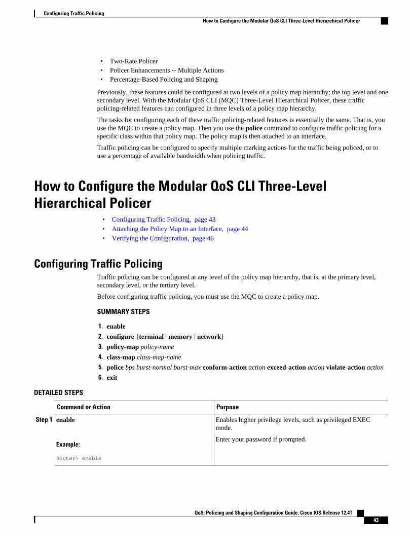
• Two-Rate Policer• Policer Enhancements -- Multiple Actions• Percentage-Based Policing and Shaping
Previously, these features could be configured at two levels of a policy map hierarchy; the top level and onesecondary level. With the Modular QoS CLI (MQC) Three-Level Hierarchical Policer, these trafficpolicing-related features can configured in three levels of a policy map hierarchy.
The tasks for configuring each of these traffic policing-related features is essentially the same. That is, youuse the MQC to create a policy map. Then you use the police command to configure traffic policing for aspecific class within that policy map. The policy map is then attached to an interface.
Traffic policing can be configured to specify multiple marking actions for the traffic being policed, or touse a percentage of available bandwidth when policing traffic.
How to Configure the Modular QoS CLI Three-LevelHierarchical Policer
• Configuring Traffic Policing, page 43
• Attaching the Policy Map to an Interface, page 44
• Verifying the Configuration, page 46
Configuring Traffic PolicingTraffic policing can be configured at any level of the policy map hierarchy, that is, at the primary level,secondary level, or the tertiary level.
Before configuring traffic policing, you must use the MQC to create a policy map.
SUMMARY STEPS
1. enable
2. configure {terminal | memory | network}
3. policy-map policy-name
4. class-map class-map-name
5. police bps burst-normal burst-max conform-action action exceed-action action violate-action action
6. exit
DETAILED STEPS
Command or Action Purpose
Step 1 enable
Example:
Router> enable
Enables higher privilege levels, such as privileged EXECmode.
Enter your password if prompted.
Configuring Traffic PolicingHow to Configure the Modular QoS CLI Three-Level Hierarchical Policer
QoS: Policing and Shaping Configuration Guide, Cisco IOS Release 12.4T 43
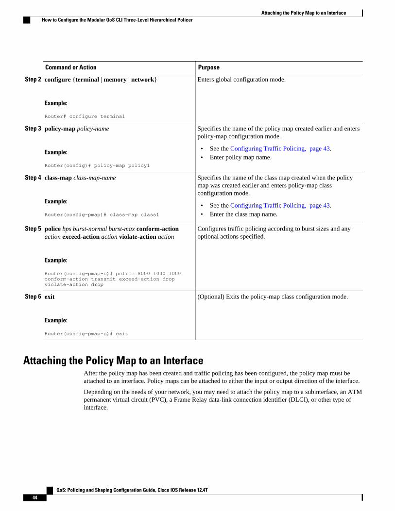
Command or Action Purpose
Step 2 configure {terminal | memory | network}
Example:
Router# configure terminal
Enters global configuration mode.
Step 3 policy-map policy-name
Example:
Router(config)# policy-map policy1
Specifies the name of the policy map created earlier and enterspolicy-map configuration mode.
• See the Configuring Traffic Policing, page 43.• Enter policy map name.
Step 4 class-map class-map-name
Example:
Router(config-pmap)# class-map class1
Specifies the name of the class map created when the policymap was created earlier and enters policy-map classconfiguration mode.
• See the Configuring Traffic Policing, page 43.• Enter the class map name.
Step 5 police bps burst-normal burst-max conform-actionaction exceed-action action violate-action action
Example:
Router(config-pmap-c)# police 8000 1000 1000 conform-action transmit exceed-action drop violate-action drop
Configures traffic policing according to burst sizes and anyoptional actions specified.
Step 6 exit
Example:
Router(config-pmap-c)# exit
(Optional) Exits the policy-map class configuration mode.
Attaching the Policy Map to an InterfaceAfter the policy map has been created and traffic policing has been configured, the policy map must beattached to an interface. Policy maps can be attached to either the input or output direction of the interface.
Depending on the needs of your network, you may need to attach the policy map to a subinterface, an ATMpermanent virtual circuit (PVC), a Frame Relay data-link connection identifier (DLCI), or other type ofinterface.
Attaching the Policy Map to an Interface How to Configure the Modular QoS CLI Three-Level Hierarchical Policer
QoS: Policing and Shaping Configuration Guide, Cisco IOS Release 12.4T44

SUMMARY STEPS
1. enable
2. configure {terminal | memory | network}
3. interface type number
4. pvc [name] vpi / vci [ilmi | qsaal | smds]
5. service-policy {input| output} policy-map-name
6. exit
DETAILED STEPS
Command or Action Purpose
Step 1 enable
Example:
Router> enable
Enables higher privilege levels, such as privileged EXEC mode.
• Enter your password if prompted.
Step 2 configure {terminal | memory | network}
Example:
Router# configure terminal
Enters global configuration mode.
Step 3 interface type number
Example:
Example:
Router(config-if)# interface s4/0
Configures an interface (or subinterface) type and enters interfaceconfiguration mode.
• Enter the interface type number.
Step 4 pvc [name] vpi / vci [ilmi | qsaal | smds]
Example:
Router(config-if)# pvc cisco 0/16 ilmi
(Optional) Creates or assigns a name to an ATM PVC and specifies theencapsulation type on an ATM PVC. Enters ATM virtual circuit (VC)configuration mode (config-if-atm-vc).
Note This step is required only if you are attaching the policy map to anATM PVC. If you are not attaching the policy map to an ATM PVC,skip this step and proceed with Attaching the Policy Map to anInterface, page 44.
Modular QoS CLI Three-Level Hierarchical PolicerHow to Configure the Modular QoS CLI Three-Level Hierarchical Policer
QoS: Policing and Shaping Configuration Guide, Cisco IOS Release 12.4T 45
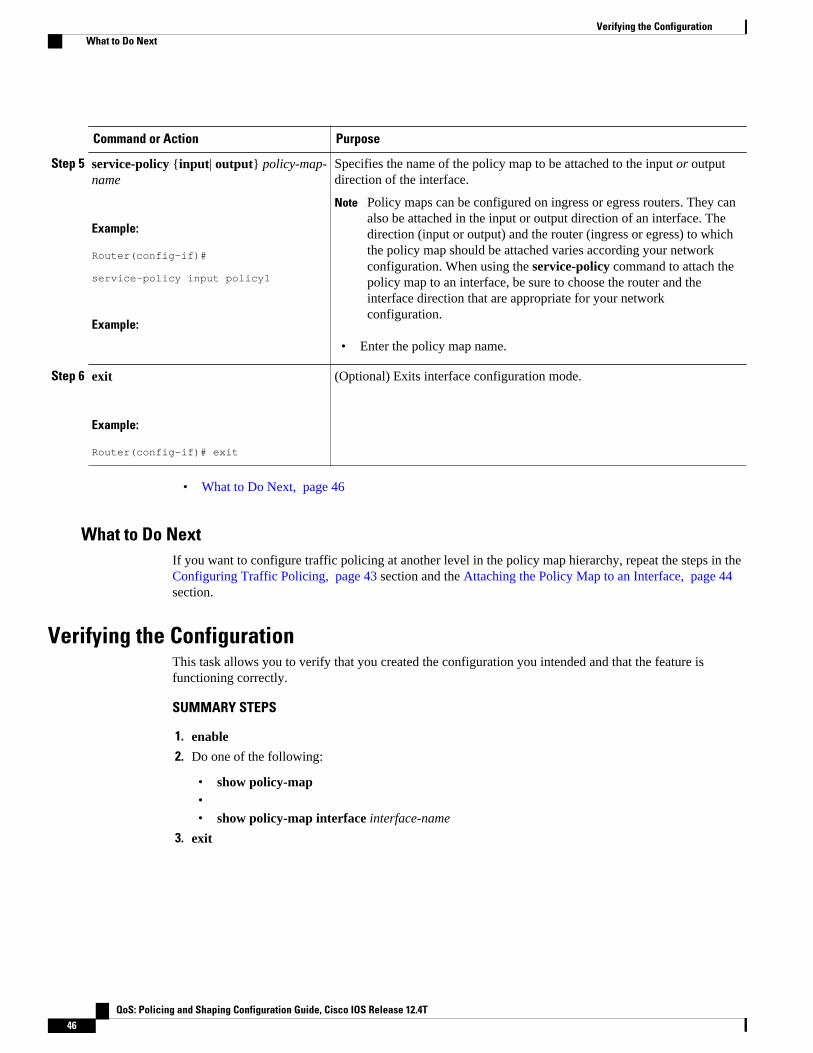
Command or Action Purpose
Step 5 service-policy {input| output} policy-map-name
Example:
Router(config-if)# service-policy input policy1
Example:
Specifies the name of the policy map to be attached to the input or outputdirection of the interface.
Note Policy maps can be configured on ingress or egress routers. They canalso be attached in the input or output direction of an interface. Thedirection (input or output) and the router (ingress or egress) to whichthe policy map should be attached varies according your networkconfiguration. When using the service-policy command to attach thepolicy map to an interface, be sure to choose the router and theinterface direction that are appropriate for your networkconfiguration.
• Enter the policy map name.
Step 6 exit
Example:
Router(config-if)# exit
(Optional) Exits interface configuration mode.
• What to Do Next, page 46
What to Do NextIf you want to configure traffic policing at another level in the policy map hierarchy, repeat the steps in the Configuring Traffic Policing, page 43 section and the Attaching the Policy Map to an Interface, page 44section.
Verifying the ConfigurationThis task allows you to verify that you created the configuration you intended and that the feature isfunctioning correctly.
SUMMARY STEPS
1. enable
2. Do one of the following:
• show policy-map•• show policy-map interface interface-name
3. exit
Verifying the Configuration What to Do Next
QoS: Policing and Shaping Configuration Guide, Cisco IOS Release 12.4T46

DETAILED STEPS
Command or Action Purpose
Step 1 enable
Example:
Router> enable
Enables higher privilege levels, such as privileged EXEC mode.
• Enter your password if prompted.
Step 2 Do one of the following:
• show policy-map•• show policy-map interface interface-name
Example:
Router# show policy-map
Example:
Example:
Router# show policy-map interface s4/0
Displays all configured policy maps.
or
Displays the packet statistics of all classes that are configured for allservice policies either on the specified interface or subinterface or on aspecific PVC on the interface.
• Enter the interface name.
Step 3 exit
Example:
Router(config-if)# exit
(Optional) Exits interface configuration mode.
• Troubleshooting Tips, page 47
Troubleshooting TipsThe commands in the Verifying the Configuration, page 46 section allow you to verify that you achievedthe intended configuration and that the feature is functioning correctly. If after using the show commandslisted above, the configuration is not correct or the feature is not functioning as expected, do the following:
If the configuration is not the one you intended, complete the following procedures:
• Use the show running-config command and analyze the output of the command.• If the policy map does not appear in the output of the show running-config command, enable the
logging console command.• Attach the policy map to the interface again.
Modular QoS CLI Three-Level Hierarchical PolicerTroubleshooting Tips
QoS: Policing and Shaping Configuration Guide, Cisco IOS Release 12.4T 47
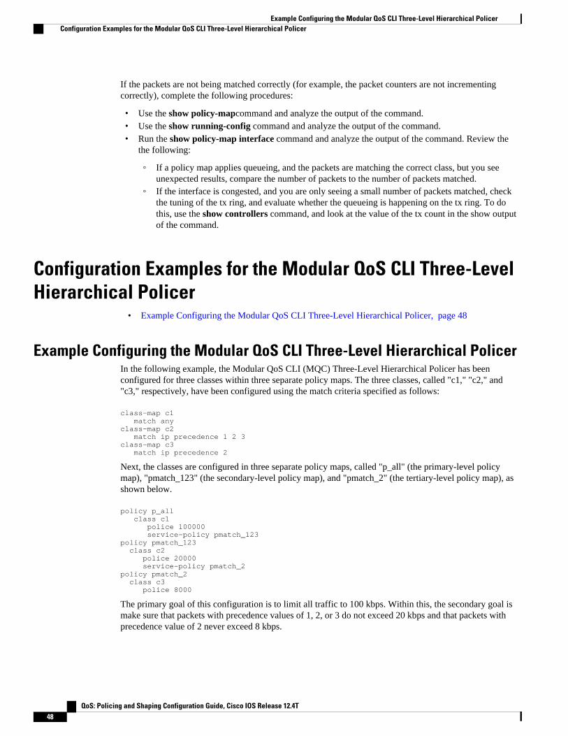
If the packets are not being matched correctly (for example, the packet counters are not incrementingcorrectly), complete the following procedures:
• Use the show policy-mapcommand and analyze the output of the command.• Use the show running-config command and analyze the output of the command.• Run the show policy-map interface command and analyze the output of the command. Review the
the following:
◦ If a policy map applies queueing, and the packets are matching the correct class, but you seeunexpected results, compare the number of packets to the number of packets matched.
◦ If the interface is congested, and you are only seeing a small number of packets matched, checkthe tuning of the tx ring, and evaluate whether the queueing is happening on the tx ring. To dothis, use the show controllers command, and look at the value of the tx count in the show outputof the command.
Configuration Examples for the Modular QoS CLI Three-LevelHierarchical Policer
• Example Configuring the Modular QoS CLI Three-Level Hierarchical Policer, page 48
Example Configuring the Modular QoS CLI Three-Level Hierarchical PolicerIn the following example, the Modular QoS CLI (MQC) Three-Level Hierarchical Policer has beenconfigured for three classes within three separate policy maps. The three classes, called "c1," "c2," and"c3," respectively, have been configured using the match criteria specified as follows:
class-map c1 match anyclass-map c2 match ip precedence 1 2 3class-map c3 match ip precedence 2
Next, the classes are configured in three separate policy maps, called "p_all" (the primary-level policymap), "pmatch_123" (the secondary-level policy map), and "pmatch_2" (the tertiary-level policy map), asshown below.
policy p_all class c1 police 100000 service-policy pmatch_123policy pmatch_123 class c2 police 20000 service-policy pmatch_2policy pmatch_2 class c3 police 8000
The primary goal of this configuration is to limit all traffic to 100 kbps. Within this, the secondary goal ismake sure that packets with precedence values of 1, 2, or 3 do not exceed 20 kbps and that packets withprecedence value of 2 never exceed 8 kbps.
Example Configuring the Modular QoS CLI Three-Level Hierarchical Policer Configuration Examples for the Modular QoS CLI Three-Level Hierarchical Policer
QoS: Policing and Shaping Configuration Guide, Cisco IOS Release 12.4T48

To verify that the classes have been configured correctly and to confirm the results of the traffic policingconfiguration in the policy maps, the show policy-map command and the show policy-mapinterfacecommand can be used, as shown in the following sections.
The following sample output of the show policy-mapcommand verifies the configuration of the classes inthe policy maps:
Router# show policy map Policy Map p_all Class c1 police cir 100000 bc 3000 conform-action transmit exceed-action drop service-policy pmatch_123 Policy Map pmatch_123 Class c2 police cir 20000 bc 1500 conform-action transmit exceed-action drop service-policy pmatch_2 Policy Map pmatch_2 Class c3 police cir 8000 bc 1500 conform-action transmit exceed-action drop
The following sample output of the show policy-map interface command confirms the results of thisconfiguration on the attached interface:
Router# show policy-map interface Ethernet3/1 Ethernet3/1 Service-policy output:p_all Class-map:c1 (match-all) 0 packets, 0 bytes 5 minute offered rate 0 bps, drop rate 0 bps Match:any police: cir 100000 bps, bc 3000 bytes conformed 0 packets, 0 bytes; actions: transmit exceeded 0 packets, 0 bytes; actions: drop conformed 0 bps, exceed 0 bps, Service-policy :pmatch_123 Class-map:c2 (match-all) 0 packets, 0 bytes 5 minute offered rate 0 bps, drop rate 0 bps Match:ip precedence 1 2 3 police: cir 20000 bps, bc 1500 bytes conformed 0 packets, 0 bytes; actions: transmit exceeded 0 packets, 0 bytes; actions: drop conformed 0 bps, exceed 0 bps, Service-policy :pmatch_2 Class-map:c3 (match-all) 0 packets, 0 bytes 5 minute offered rate 0 bps, drop rate 0 bps Match:ip precedence 2 police: cir 8000 bps, bc 1500 bytes conformed 0 packets, 0 bytes; actions: transmit exceeded 0 packets, 0 bytes; actions: drop conformed 0 bps, exceed 0 bps, Class-map:class-default (match-any) 0 packets, 0 bytes 5 minute offered rate 0 bps, drop rate 0 bps
Modular QoS CLI Three-Level Hierarchical PolicerConfiguration Examples for the Modular QoS CLI Three-Level Hierarchical Policer
QoS: Policing and Shaping Configuration Guide, Cisco IOS Release 12.4T 49
Match:any Class-map:class-default (match-any) 0 packets, 0 bytes 5 minute offered rate 0 bps, drop rate 0 bps Match:any Class-map:class-default (match-any) 0 packets, 0 bytes 5 minute offered rate 0 bps, drop rate 0 bps Match:any
Additional ReferencesThe following sections provide additional references related to the Modular QoS CLI (MQC) Three-LevelHierarchical Policer:
Related Documents
Related Topic Document Title
QoS commands: complete command syntax,command modes, command history, defaults, usageguidelines, and examples
Cisco IOS Quality of Service Solutions CommandReference
Additional information about configuring trafficpolicing
"Policing and Shaping Overview" module
Modular Quality of Service (QoS) Command-LineInterface (CLI) (MQC)
"Applying QoS Features Using the MQC" module
Two-rate traffic policing "Two-Rate Policer" module
Traffic policing using multiple policer actions "Policer Enhancements--Multiple Actions" module
Percentage-based traffic policing and shaping "Percentage-Based Policing and Shaping" module
Frame Relay configurations "Configuring Frame Relay" module
Frame Relay commands: complete commandsyntax, command modes, command history,defaults, usage guidelines, and examples
Cisco IOS Wide-Area Networking CommandReference
Standards
Standards Title
No new or modified standards are supported by thisfeature, and support for existing standards has notbeen modified by this feature.
--
Modular QoS CLI Three-Level Hierarchical Policer Additional References
QoS: Policing and Shaping Configuration Guide, Cisco IOS Release 12.4T50

MIBs
MIBs MIBs Link
• CISCO-CLASS-BASED-QOS-CAPABILITY-MIB
• CISCO-CLASS-BASED-QOS-MIB
To obtain lists of supported MIBs by platform andCisco IOS release, and to download MIB modules,go to the Cisco MIB website on Cisco.com at thefollowing URL:
http://www.cisco.com/public/sw-center/netmgmt/cmtk/mibs.shtml
RFCs
RFCs Title
RFC 2697 A Single Rate Three Color Marker
RFC 2698 A Two Rate Three Color Marker
Technical Assistance
Description Link
The Cisco Support and Documentation websiteprovides online resources to downloaddocumentation, software, and tools. Use theseresources to install and configure the software andto troubleshoot and resolve technical issues withCisco products and technologies. Access to mosttools on the Cisco Support and Documentationwebsite requires a Cisco.com user ID andpassword.
http://www.cisco.com/cisco/web/support/index.html
Cisco and the Cisco logo are trademarks or registered trademarks of Cisco and/or its affiliates in the U.S.and other countries. To view a list of Cisco trademarks, go to this URL: www.cisco.com/go/trademarks.Third-party trademarks mentioned are the property of their respective owners. The use of the word partnerdoes not imply a partnership relationship between Cisco and any other company. (1110R)
Any Internet Protocol (IP) addresses and phone numbers used in this document are not intended to beactual addresses and phone numbers. Any examples, command display output, network topology diagrams,and other figures included in the document are shown for illustrative purposes only. Any use of actual IPaddresses or phone numbers in illustrative content is unintentional and coincidental.
Modular QoS CLI Three-Level Hierarchical Policer
QoS: Policing and Shaping Configuration Guide, Cisco IOS Release 12.4T 51
Example Configuring the Modular QoS CLI Three-Level Hierarchical Policer
QoS: Policing and Shaping Configuration Guide, Cisco IOS Release 12.4T52

ATM Policing by Service Category for SVC andSoftPVC
Feature History
Release Modification
12.2(4)B This feature was introduced on the Cisco 6400NSP.
12.2(13)T This command was integrated into Cisco IOSRelease 12.2(13)T.
This module describes the ATM Policing by Service Category for SVC/SoftPVC feature in Cisco IOSRelease 12.2(13)T and includes the following sections:
• Finding Feature Information, page 53• Feature Overview, page 53• Supported Platforms, page 54• Supported Standards MIBs and RFCs, page 54• Configuration Tasks, page 55• Monitoring and Maintaining ATM Policing by Service Category for SVC and SoftPVC, page 57• Configuration Examples, page 58
Finding Feature InformationYour software release may not support all the features documented in this module. For the latest featureinformation and caveats, see the release notes for your platform and software release. To find informationabout the features documented in this module, and to see a list of the releases in which each feature issupported, see the Feature Information Table at the end of this document.
Use Cisco Feature Navigator to find information about platform support and Cisco software image support.To access Cisco Feature Navigator, go to www.cisco.com/go/cfn. An account on Cisco.com is not required.
Feature OverviewWhen configured, an ATM switch at the network side of a user-to-network (UNI) interface polices the flowof cells in the forward (into the network) direction of a virtual connection. These traffic policingmechanisms are known as usage parameter control (UPC). With UPC, the switch determines whether
QoS: Policing and Shaping Configuration Guide, Cisco IOS Release 12.4T 53

received cells comply with the negotiated traffic management values and takes one of the following actionson violating cells:
• Pass the cell without changing the cell loss priority (CLP) bit in the cell header.• Tag the cell with a CLP bit value of 1.• Drop (discard) the cell.
The SVC/SoftPVC feature enables you to specify which traffic to police, based on service category, onswitched virtual circuits (SVCs) or terminating VCs on the destination end of a soft VC.
• Benefits, page 54
• Related Features and Technologies, page 54
• Related Documents, page 54
BenefitsThis feature enables you to select which and how traffic is affected by UPC. For example, you canconfigure your switch to pass all UBR traffic, but tag all other traffic types.
Related Features and Technologies• Intelligent early packet discard (EPD)• Intelligent partial (tail) packet discard
Related Documents• ATM Switch Router Software Configuration Guide• ATM and Layer 3 Switch Router Command Reference• Guide to ATM Technology• ATM Forum UNI 3.1 Specification
Supported PlatformsThis feature is supported on the node switch processor (NSP) of the Cisco 6400 carrier-class broadbandaggregator.
Supported Standards MIBs and RFCsStandards
None
MIBs
CISCO-ATM-IF-MIB.my--New objects were created for per-service category SVC UPC intent.
Benefits Supported Platforms
QoS: Policing and Shaping Configuration Guide, Cisco IOS Release 12.4T54

To obtain lists of supported MIBs by platform and Cisco IOS release, and to download MIB modules, go tothe Cisco MIB website on Cisco.com at the following URL:
http://www.cisco.com/public/sw-center/netmgmt/cmtk/mibs.shtml
RFCs
None
Configuration Tasks• Configuring ATM Policing by Service Category for SVC and SoftPVC, page 55• Verifying ATM Policing by Service Category for SVC and SoftPVC, page 55• Troubleshooting Tips, page 56
Configuring ATM Policing by Service Category for SVC and SoftPVC
SUMMARY STEPS
1. Switch(config)# interface atmslot/subslot/port
2. Switch(config-if)# atm svc-upc-intent [{abr | cbr | vbr-rt | vbr-nrt | ubr}] {tag | pass | drop}
DETAILED STEPS
Command or Action Purpose
Step 1 Switch(config)# interface atmslot/subslot/port Selects the ATM interface.
Step 2 Switch(config-if)# atm svc-upc-intent [{abr | cbr | vbr-rt | vbr-nrt |ubr}] {tag | pass | drop}
Example:
Example:
(Repeat this step for each service category and UPC mode combination.)
Specifies the UPC mode. If no servicecategory is specified, then the UPC modeconfiguration is applied to all traffic types.
Verifying ATM Policing by Service Category for SVC and SoftPVC
SUMMARY STEPS
1. Enter the show atm vc or show atm vp EXEC command to display the UPC mode for a particular VCor VP.
2. Enter the show atm interface EXEC command. If the UPC mode is not the same for all servicecategories, the "Svc Upc Intent" field displays "by sc."
Configuring ATM Policing by Service Category for SVC and SoftPVCConfiguration Tasks
QoS: Policing and Shaping Configuration Guide, Cisco IOS Release 12.4T 55
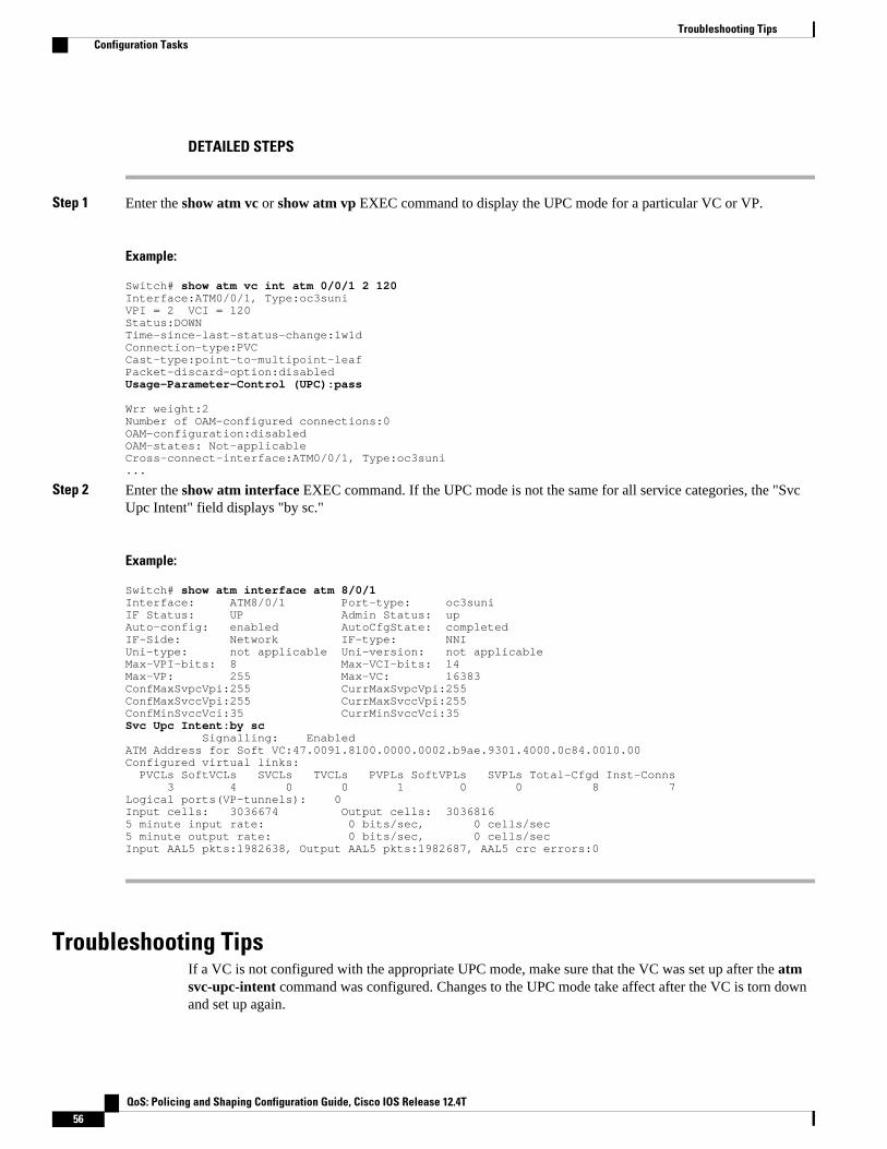
DETAILED STEPS
Step 1 Enter the show atm vc or show atm vp EXEC command to display the UPC mode for a particular VC or VP.
Example:
Switch# show atm vc int atm 0/0/1 2 120Interface:ATM0/0/1, Type:oc3suni VPI = 2 VCI = 120Status:DOWNTime-since-last-status-change:1w1dConnection-type:PVC Cast-type:point-to-multipoint-leafPacket-discard-option:disabledUsage-Parameter-Control (UPC):pass Wrr weight:2Number of OAM-configured connections:0OAM-configuration:disabledOAM-states: Not-applicableCross-connect-interface:ATM0/0/1, Type:oc3suni ...
Step 2 Enter the show atm interface EXEC command. If the UPC mode is not the same for all service categories, the "SvcUpc Intent" field displays "by sc."
Example:
Switch# show atm interface atm 8/0/1Interface: ATM8/0/1 Port-type: oc3suniIF Status: UP Admin Status: upAuto-config: enabled AutoCfgState: completedIF-Side: Network IF-type: NNIUni-type: not applicable Uni-version: not applicableMax-VPI-bits: 8 Max-VCI-bits: 14Max-VP: 255 Max-VC: 16383ConfMaxSvpcVpi:255 CurrMaxSvpcVpi:255ConfMaxSvccVpi:255 CurrMaxSvccVpi:255ConfMinSvccVci:35 CurrMinSvccVci:35Svc Upc Intent:by sc Signalling: EnabledATM Address for Soft VC:47.0091.8100.0000.0002.b9ae.9301.4000.0c84.0010.00Configured virtual links: PVCLs SoftVCLs SVCLs TVCLs PVPLs SoftVPLs SVPLs Total-Cfgd Inst-Conns 3 4 0 0 1 0 0 8 7Logical ports(VP-tunnels): 0Input cells: 3036674 Output cells: 30368165 minute input rate: 0 bits/sec, 0 cells/sec5 minute output rate: 0 bits/sec, 0 cells/secInput AAL5 pkts:1982638, Output AAL5 pkts:1982687, AAL5 crc errors:0
Troubleshooting TipsIf a VC is not configured with the appropriate UPC mode, make sure that the VC was set up after the atmsvc-upc-intent command was configured. Changes to the UPC mode take affect after the VC is torn downand set up again.
Troubleshooting Tips Configuration Tasks
QoS: Policing and Shaping Configuration Guide, Cisco IOS Release 12.4T56

Monitoring and Maintaining ATM Policing by ServiceCategory for SVC and SoftPVC
Command Purpose
Switch# show atm interfaceDisplays ATM-specific information about an ATMinterface.
Switch# show controllers atm slot/subslot/port
Displays information about a physical port device.Includes dropped (or discarded) cells.
Switch# show atm vc [interface atm slot/subslot/port]
Displays the configured UPC action and intelligentpacket discard mechanisms, as well as the numberof cells discarded due to UPC violations.
• Example Monitoring and Maintaining ATM Policing by Service Category for SVC and SoftPVC, page 57
Example Monitoring and Maintaining ATM Policing by Service Category forSVC and SoftPVC
Switch# show atm vc interface atm 3/0/1.51 51 16 Interface: ATM3/0/1.51, Type: oc3suni VPI = 51 VCI = 16 Status: DOWN Time-since-last-status-change: 2w0d Connection-type: PVC Cast-type: point-to-point Packet-discard-option: enabled Usage-Parameter-Control (UPC): pass Wrr weight: 32 Number of OAM-configured connections: 0 OAM-configuration: disabled OAM-states: Not-applicable Cross-connect-interface: ATM2/0/0, Type: ATM Swi/Proc Cross-connect-VPI = 0 Cross-connect-VCI = 73 Cross-connect-UPC: pass Cross-connect OAM-configuration: disabled Cross-connect OAM-state: Not-applicable Encapsulation: AAL5ILMI Threshold Group: 6, Cells queued: 0 Rx cells: 0, Tx cells: 0 Tx Clp0:0, Tx Clp1: 0 Rx Clp0:0, Rx Clp1: 0 Rx Upc Violations:0, Rx cell drops:0 Rx pkts:0, Rx pkt drops:0 Rx connection-traffic-table-index: 6 Rx service-category: UBR (Unspecified Bit Rate) Rx pcr-clp01: 424 Rx scr-clp01: none Rx mcr-clp01: none Rx cdvt: 1024 (from default for interface) Rx mbs: none
Example Monitoring and Maintaining ATM Policing by Service Category for SVC and SoftPVCMonitoring and Maintaining ATM Policing by Service Category for SVC and SoftPVC
QoS: Policing and Shaping Configuration Guide, Cisco IOS Release 12.4T 57

Tx connection-traffic-table-index: 6 Tx service-category: UBR (Unspecified Bit Rate) Tx pcr-clp01: 424 Tx scr-clp01: none Tx mcr-clp01: none Tx cdvt: none Tx mbs: none No AAL5 connection registered
Configuration Examples• Example Non-UBR Traffic Policing, page 58
Example Non-UBR Traffic PolicingIn the following example, the UBR traffic on ATM 3/0/0 is passed while all other traffic is policed:
Switch(config)# interface atm 3/0/0Switch(config-if)# atm svc-upc-intent ubr passSwitch(config-if)# atm svc-upc-intent cbr tagSwitch(config-if)# atm svc-upc-intent vbr-rt tagSwitch(config-if)# atm svc-upc-intent vbr-nrt tagSwitch(config-if)# atm svc-upc-intent abr drop
Cisco and the Cisco logo are trademarks or registered trademarks of Cisco and/or its affiliates in the U.S.and other countries. To view a list of Cisco trademarks, go to this URL: www.cisco.com/go/trademarks.Third-party trademarks mentioned are the property of their respective owners. The use of the word partnerdoes not imply a partnership relationship between Cisco and any other company. (1110R)
Any Internet Protocol (IP) addresses and phone numbers used in this document are not intended to beactual addresses and phone numbers. Any examples, command display output, network topology diagrams,and other figures included in the document are shown for illustrative purposes only. Any use of actual IPaddresses or phone numbers in illustrative content is unintentional and coincidental.
Example Non-UBR Traffic Policing Configuration Examples
QoS: Policing and Shaping Configuration Guide, Cisco IOS Release 12.4T58

Modular QoS CLI Unconditional PacketDiscard
Feature History
Release Modification
12.2(13)T This feature was introduced.
Supported Platforms
For platforms supported in Cisco IOS Release12.2(13)T, consult Cisco Feature Navigator.
This module describes the Modular QoS CLI (MQC) Unconditional Packet Discard feature in Cisco IOSRelease 12.2(13)T. It includes the following sections:
• Finding Feature Information, page 59• Feature Overview, page 59• Supported Standards MIBs and RFCs, page 60• Configuration Tasks, page 61• Configuration Examples, page 64
Finding Feature InformationYour software release may not support all the features documented in this module. For the latest featureinformation and caveats, see the release notes for your platform and software release. To find informationabout the features documented in this module, and to see a list of the releases in which each feature issupported, see the Feature Information Table at the end of this document.
Use Cisco Feature Navigator to find information about platform support and Cisco software image support.To access Cisco Feature Navigator, go to www.cisco.com/go/cfn. An account on Cisco.com is not required.
Feature OverviewThe Modular QoS CLI (MQC) Unconditional Packet Discard feature allows customers to classify trafficmatching certain criteria and then configure the system to unconditionally discard any packets matchingthat criteria. The Modular QoS CLI (MQC) Unconditional Packet Discard feature is configured using theModular Quality of Service Command-Line Interface (MQC) feature. Packets are unconditionallydiscarded by using the new drop command within the MQC.
QoS: Policing and Shaping Configuration Guide, Cisco IOS Release 12.4T 59

• Benefits, page 60
• Restrictions, page 60
• Related Features and Technologies, page 60
• Related Documents, page 60
Benefits
Enhanced System Utilization
This feature allows you to discard (drop), without any further system processing, the packets of a particularclass. This function is very useful when you want to discard all the packets for nonessential applications(for instance, Internet browsing applications or unauthorized video applications) and allocate systemresources to more essential applications. This feature allows the user to discard those nonessential packetsand simultaneously obtain the bit and drop rate statistics for that particular class and the traffic within thatclass. The statistics are gathered through the CISCO-CLASS-BASED-QOS-MIB.
RestrictionsPackets are unconditionally discarded by configuring the drop action inside a traffic class (inside of apolicy map). This drop action is accomplished with the new drop command. Note the following restrictionsfor configuring the drop action within a traffic class:
• The discarding action is the only action that can be configured in a traffic class. That is, no otheractions can be configured in the traffic class.
• When a traffic class is configured with the drop command, a "child" (nested) policy cannot beconfigured for this specific traffic class through the service policy command.
• The discarding action cannot be configured for the default class known as the class-default class.
Related Features and Technologies• Modular quality of service command-line interface (MQC)
Related Documents• "Applying QoS Features Using the MQC" module• "Classifying Network Traffic" module• "Marking Network Traffic" module• Cisco IOS Quality of Service Solutions Command Reference
Supported Standards MIBs and RFCsStandards
None
Benefits Supported Standards MIBs and RFCs
QoS: Policing and Shaping Configuration Guide, Cisco IOS Release 12.4T60
MIBs
• CISCO-CLASS-BASED-QOS-MIB• CISCO-CLASS-BASED-QOS-CAPABILITY-MIB
To locate and download MIBs for selected platforms, Cisco IOS releases, and feature sets, use Cisco MIBLocator found at the following URL:
http://tools.cisco.com/ITDIT/MIBS/servlet/index
If Cisco MIB Locator does not support the MIB information that you need, you can also obtain a list ofsupported MIBs and download MIBs from the Cisco MIBs page at the following URL:
http://www.cisco.com/public/sw-center/netmgmt/cmtk/mibs.shtml
To access Cisco MIB Locator, you must have an account on Cisco.com. If you have forgotten or lost youraccount information, send a blank e-mail to [email protected]. An automatic check will verify thatyour e-mail address is registered with Cisco.com. If the check is successful, account details with a newrandom password will be e-mailed to you. Qualified users can establish an account on Cisco.com byfollowing the directions found at this URL:
http://www.cisco.com/register
RFCs
None
Configuration Tasks• Configuring the Class Map, page 61
• Creating a Policy Map, page 62
• Attaching the Policy Map to an Interface or a VC, page 63
• Verifying the Discard Action Configuration in the Traffic Class, page 64
Configuring the Class Map
SUMMARY STEPS
1. Router(config)# class-mapclass-map-name
2. Router(config-cmap)# match access-group {access-group | nameaccess-group-name }
3. Router(config-cmap)# exit
DETAILED STEPS
Command or Action Purpose
Step 1 Router(config)# class-mapclass-map-name
Specifies the name of the class map to be created. If match-all or match-any is notspecified, traffic must match all the match criteria to be classified as part of the trafficclass. Enters class-map configuration mode.
Configuring the Class MapConfiguration Tasks
QoS: Policing and Shaping Configuration Guide, Cisco IOS Release 12.4T 61

Command or Action Purpose
Step 2 Router(config-cmap)# matchaccess-group {access-group |nameaccess-group-name }
Specifies that traffic matching the specified access group will be placed in the mapclass created above. This command provides just an example of the match criterionyou can specify. For more information about the additional match criteria available,see the "Applying QoS Features Using the MQC" module.
Step 3 Router(config-cmap)# exit Exits from the configuration mode.
Creating a Policy Map
SUMMARY STEPS
1. Router (config)# policy-mappolicy-name
2. Router (config-pmap)# classclass-name
3. Router (config-pmap)# drop
4. Router(config-cmap)# exit
DETAILED STEPS
Command or Action Purpose
Step 1 Router (config)# policy-mappolicy-name
Example:
Specifies the name of the policy map to be created. Enters policy-mapconfiguration mode.
Step 2 Router (config-pmap)# classclass-name Specifies the name of the traffic class configured earlier in the Configuring theClass Map, page 61 section above. This traffic class is used to classify traffic tothe policy map. Enters policy-map class configuration mode.
Step 3 Router (config-pmap)# drop Discards the packets in the specified traffic class.
Step 4 Router(config-cmap)# exit Exits policy-map configuration mode.
Creating a Policy Map Configuration Tasks
QoS: Policing and Shaping Configuration Guide, Cisco IOS Release 12.4T62

Attaching the Policy Map to an Interface or a VC
SUMMARY STEPS
1. Router(config)# interfacetype number [ name-tag
2. Router(config-if)# pvc [name] vpi/vci [ilmi | qsaal | smds]
3. Do one of the following:
• Router(config-if)# service-policy inputpolicy-map-name•••
4. Router(config-if)# exit
DETAILED STEPS
Command or Action Purpose
Step 1 Router(config)# interfacetype number [ name-tag
Example:
Configures the interface type and enters interface configurationmode.
Step 2 Router(config-if)# pvc [name] vpi/vci [ilmi | qsaal |smds]
(Optional) Creates or assigns a name to an ATM permanent virtualcircuit (PVC), and specifies the encapsulation type on an ATMPVC.
Enters ATM VC configuration mode (config-if-atm-vc).
This step is required only if you are attaching the policy map to anATM PVC.
Step 3 Do one of the following:
• Router(config-if)# service-policy inputpolicy-map-name
•••
Example:
Router(config-if-atm-vc)#
service-policy outputpolicy-map-name
Example:
Specifies the name of the policy map to be attached to the input oroutput direction of an interface or VC. The policy map evaluates alltraffic entering or leaving that interface or VC.
Attaching the Policy Map to an Interface or a VCConfiguration Tasks
QoS: Policing and Shaping Configuration Guide, Cisco IOS Release 12.4T 63

Command or Action Purpose
Step 4 Router(config-if)# exit Exits interface configuration mode.
Verifying the Discard Action Configuration in the Traffic ClassCommand Purpose
Router# show policy-mapDisplays the configuration of all classes for aspecified service policy map or all classes for allexisting policy maps.
Router# show policy-map interface interface-name
Displays the packet statistics of all classes that areconfigured for all service policies either on thespecified interface or subinterface or on a specificPVC on the interface.
Configuration Examples• Example Configuring the Discard Action Configuration in a Traffic Class, page 64
• Example Verifying the Discard Action Configuration in the Policy Map, page 64
Example Configuring the Discard Action Configuration in a Traffic ClassIn the following sample configuration, a traffic class called "class1" has been created and configured foruse in a policy-map called "policy1." The policy-map policy1 is attached to an output serial interface 2/0.All packets matching access-group 101 are placed in a class called "c1." Packets belonging to this class arediscarded.
Router(config)# class-map class1Router(config-cmap)# match access-group 101Router(config-cmap)# policy-map policy1Router(config-pmap)# class c1Router(config-pmap-c)# dropRouter(config-pmap-c)# interface s2/0Router(config-if)# service-policy output policy1Router(config-if)# exit
The following sample output of the show policy-map command displays the contents of the policy mapcalled "policy1." All the packets belonging to the class called "c1" are discarded.
Router# show policy-map policy1 Policy Map policy1 Class c1 drop
Example Verifying the Discard Action Configuration in the Policy MapThe following sample output of the show policy-map interface command displays the statistics for theSerial2/0 interface, to which a policy map called "policy1" is attached. The discard action has been
Verifying the Discard Action Configuration in the Traffic Class Configuration Examples
QoS: Policing and Shaping Configuration Guide, Cisco IOS Release 12.4T64

specified for all the packets belonging to a class called "c1." In this example, 32000 bps of traffic is sent("offered") to the class and all of them are dropped. Therefore, the drop rate shows 32000 bps.
Router# show policy-map interface Serial2/0 Serial2/0 Service-policy output: policy1 Class-map: c1 (match-all) 10184 packets, 1056436 bytes 5 minute offered rate 32000 bps, drop rate 32000 bps Match: ip precedence 0 drop
Cisco and the Cisco logo are trademarks or registered trademarks of Cisco and/or its affiliates in the U.S.and other countries. To view a list of Cisco trademarks, go to this URL: www.cisco.com/go/trademarks.Third-party trademarks mentioned are the property of their respective owners. The use of the word partnerdoes not imply a partnership relationship between Cisco and any other company. (1110R)
Any Internet Protocol (IP) addresses and phone numbers used in this document are not intended to beactual addresses and phone numbers. Any examples, command display output, network topology diagrams,and other figures included in the document are shown for illustrative purposes only. Any use of actual IPaddresses or phone numbers in illustrative content is unintentional and coincidental.
Modular QoS CLI Unconditional Packet Discard
QoS: Policing and Shaping Configuration Guide, Cisco IOS Release 12.4T 65

Example Verifying the Discard Action Configuration in the Policy Map
QoS: Policing and Shaping Configuration Guide, Cisco IOS Release 12.4T66
Control Plane Policing
The Control Plane Policing feature allows you to configure a quality of service (QoS) filter that managesthe traffic flow of control plane packets to protect the control plane of Cisco IOS routers and switchesagainst reconnaissance and denial-of-service (DoS) attacks. In this way, the control plane (CP) can helpmaintain packet forwarding and protocol states despite an attack or heavy traffic load on the router orswitch.
• Finding Feature Information, page 67• Prerequisites for Control Plane Policing, page 67• Restrictions for Control Plane Policing, page 67• Information About Control Plane Policing, page 69• How to Use Control Plane Policing, page 75• Configuration Examples for Control Plane Policing, page 81• Additional References, page 82• Feature Information for Control Plane Policing, page 83
Finding Feature InformationYour software release may not support all the features documented in this module. For the latest featureinformation and caveats, see the release notes for your platform and software release. To find informationabout the features documented in this module, and to see a list of the releases in which each feature issupported, see the Feature Information Table at the end of this document.
Use Cisco Feature Navigator to find information about platform support and Cisco software image support.To access Cisco Feature Navigator, go to www.cisco.com/go/cfn. An account on Cisco.com is not required.
Prerequisites for Control Plane PolicingThe Modular Quality of Service (QoS) Command-Line interface (CLI) (MQC) is used to configure thepacket classification and policing functionality of the Control Plane Policing feature.
Before configuring Control Plane Policing (CoPP), you should understand the procedures for using theMQC. For information about the MQC, see the "Applying QoS Features Using the MQC" module.
Restrictions for Control Plane Policing
QoS: Policing and Shaping Configuration Guide, Cisco IOS Release 12.4T 67
Aggregate and Distributed Control Plane Policing
Aggregate policing is supported in Cisco IOS Release 12.0(29)S, Cisco IOS Release 12.2(18)S, Cisco IOSRelease 12.3(4)T, and later releases.
Distributed policing is supported only in Cisco IOS Release 12.0(30)S and later Cisco IOS 12.0S releases.
Output Rate-Limiting Support
Output rate-limiting is performed in silent (packet discard) mode. Silent mode enables a router to silentlydiscard packets using policy maps applied to output control plane traffic with the service-policy outputcommand. For more information, see the Output Rate-Limiting and Silent Mode Operation, page 75.
Output rate-limiting (policing) in silent mode is supported only in:
• Cisco IOS Release 12.2(25)S and later Cisco IOS 12.2S releases• Cisco IOS Release 12.3(4)T and later Cisco IOS 12.3T releases
Output rate-limiting is not supported for distributed control plane services in Cisco IOS 12.0S releases or inCisco IOS 12.2SX releases.
Output rate-limiting is not supported on the Cisco 7500 series and Cisco 10720 Internet router.
MQC Restrictions
The Control Plane Policing feature requires the MQC to configure packet classification and policing. Allrestrictions that apply when you use the MQC to configure policing also apply when you configure controlplane policing. Only two MQC actions are supported in policy maps--police and drop.
Note On the Cisco 10720 Internet router, only the policecommand, not the drop command, is supported inpolicy maps. In addition, in a QoS service policy that is attached to the Cisco 10720 control plane, thepolicecommand does not support set actions as arguments in conform-action, exceed-action, and violate-action parameters.
Features that require Network-Based Application Recognition (NBAR) classification may not work well atthe control plane level. The following classification (match) criteria are supported on all platforms:
• Standard and extended IP access lists (ACLs).• In class-map configuration mode: match ip dscp, match ip precedence, and match protocol arp,and
match protocol pppoecommands.
Note In the Cisco IOS 12.2SX release, the match protocol arp command is not supported.
On the Cisco 10720 Internet router, the following MQC commands are also supported in class-mapconfiguration mode: match input-interface, match mpls experimental, match protocol ipv6, and matchqos-group. When using these commands for control plane policing on the Cisco 10720 Internet router, notethe following restrictions:
• Packet classification using match criteria is not supported for packets that cannot be classified in theCisco 10720 data path, such as unknown Layer 2 encapsulation and IP options.
• The following IPv6 fields are not be supported in packet classification for IPv6 QoS on the Cisco10720 Internet router and are, therefore, not supported for control plane policing:
◦ IPv6 source and destination addresses
Control Plane Policing Restrictions for Control Plane Policing
QoS: Policing and Shaping Configuration Guide, Cisco IOS Release 12.4T68

◦ Layer 2 class of service (CoS)◦ IPv6 routing header flag◦ IPv6 undetermined transport flag◦ IPv6 flow label◦ IP Real-Time transport Protocol (RTP)
Note Packets that are not supported for QoS packet classification on the Cisco 10720 Internet router are notpoliced in the default traffic class for control plane policing.
CISCO-CLASS-BASED-QOS-MIB Control Plane Support
In Cisco IOS Release 12.3(7)T and later Cisco IOS 12.3T releases, the CISCO-CLASS-BASED-QOS-MIBis extended to manage control plane QoS policies and provide information about the control plane.
Cisco IOS Release 12.2(18)SXD1
In Cisco IOS Release 12.2(18)SXD1 and later releases, Hardware Control Plane Interface for Control PlanePolicing has the following restrictions:
• Supported only with Supervisor Engine 720. Not supported with Supervisor Engine 2.• Does not support CoPP output rate-limiting (policing).• Does not support the CoPP silent operation mode.• Cisco IOS Release 12.2(18)SXD1 and later releases automatically install the CoPP service policy on
all DFC-equipped switching modules.
For more information about control plane policing in Cisco IOS Release 12.2(18)SXD1 and later releases,see either of these publications:
• For Catalyst 6500 series switches, see the "Configuring Control Plane Policing (CoPP)" module.• For Cisco 7600 series routers, see the "Configuring Denial of Service Protection" module.
Information About Control Plane Policing• Benefits of Control Plane Policing, page 69• Terms to Understand, page 70• Control Plane Security and Packet QoS Overview, page 71• Aggregate Control Plane Services, page 72• Distributed Control Plane Services, page 73• Usage of Distributed CP Services, page 74• Output Rate-Limiting and Silent Mode Operation, page 75
Benefits of Control Plane PolicingConfiguring the Control Plane Policing feature on your Cisco router or switch provides the followingbenefits:
• Protection against DoS attacks at infrastructure routers and switches• QoS control for packets that are destined to the control plane of Cisco routers or switches
Benefits of Control Plane PolicingInformation About Control Plane Policing
QoS: Policing and Shaping Configuration Guide, Cisco IOS Release 12.4T 69

• Ease of configuration for control plane policies• Better platform reliability and availability
Terms to UnderstandBecause different platforms can have different architectures, the following set of terms is defined. Thefigure below illustrates how control plane policing works.
Figure 2 Layout of Control Plane, Central Switch Engine, Distributed Switch Engines, and Line Cards on aRouter
• Control plane (CP)--A collection of processes that run at the process level on the route processor (RP).These processes collectively provide high-level control for most Cisco IOS functions.
• Central switch engine--A device that is responsible for high-speed routing of IP packets. It alsotypically performs high-speed input and output services for nondistributed interfaces. (Seenondistributed line cards.) The central switch engine is used to implement aggregate CP protection forall interfaces on the router.
Note All IP packets that are destined for the CP should pass through the central switch engine before they areforwarded to the process level.
On the Cisco 10720 Internet router, control plane policing is implemented on Cisco Parallel eXpressForwarding (PXF) in a Toaster-based architecture. PXF is a hardware-based central switch engine that canfilter traffic at a higher rate than the route processor. PXF switches all data traffic separately from the routeprocessor. PXF packet processing occurs at an intermediate step between the nondistributed line cards andthe route processor shown in the figure above. In addition to the regular punting, PXF also punts certaintypes of packets (such as unknown Layer 2 encapsulation and packets with IP options) to the RP for furtherprocessing at interrupt level.
Terms to Understand Information About Control Plane Policing
QoS: Policing and Shaping Configuration Guide, Cisco IOS Release 12.4T70

Note On the Cisco 10720 Internet router, you can configure enhanced RP protection by using the ip option dropcommand to drop IPv4 packets with IP options that are punted to the RP by PXF. Tunneled IPv4 packetsand IPv4 packets with an unsupported encapsulation method are not dropped. For more information, see the"ACL IP Options Selective Drop" module.
• Distributed switch engine--A device that is responsible for high-speed switching of IP packets ondistributed line cards without using resources from the central switch engine. It also typically performsinput and output services for the line card. Each distributed switch engine is used to implementdistributed CP services for all ports on a line card. Input CP services distribute the processing loadacross multiple line cards and conserve vital central switch engine resources. Distributed CP servicesare optional; however, they provide a more refined level of service than aggregate services.
• Nondistributed line cards--Line cards that are responsible for receiving packets and occasionallyperforming input and output services. All packets must be forwarded to the central switch engine for arouting or switching decision. Aggregate CP services provide coverage for nondistributed line cards.
Note Distributed CP services are supported only in Cisco IOS Release 12.0(30)S and later 12.0S releases.
Control Plane Security and Packet QoS OverviewTo protect the CP on a router from DoS attacks and to provide packet QoS, the Control Plane Policingfeature treats the CP as a separate entity with its own ingress (input) and egress (output) ports, which arelike ports on a router and switch. Because the Control Plane Policing feature treats the CP as a separateentity, a set of rules can be established and associated with the ingress and egress ports of the CP.
These rules are applied only after the packet has been determined to have the CP as its destination or whena packet exits the CP. Thereafter, you can configure a service policy to prevent unwanted packets fromprogressing after a specified rate limit has been reached; for example, a system administrator can limit allTCP/SYN packets that are destined for the CP to a maximum rate of 1 megabit per second.
Control Plane Security and Packet QoS OverviewInformation About Control Plane Policing
QoS: Policing and Shaping Configuration Guide, Cisco IOS Release 12.4T 71

Input CP services are executed after router input port services have been performed and after a routingdecision on the input path has been made. As shown in the figure below, CP security and packet QoS areapplied on:
Figure 3 Input Control Plane Services: Aggregate and Distributed Services
The following types of Layer 3 packets are forwarded to the control plane and processed by aggregate anddistributed control plane policing:
• Routing protocol control packets• Packets destined for the local IP address of the router• Packets from management protocols (such as Simple Network Management Protocol [SNMP], Telnet,
and secure shell [SSH])
Note Ensure that Layer 3 control packets have priority over other packet types that are destined for the controlplane.
Aggregate Control Plane ServicesAggregate control plane services provide control plane policing for all CP packets that are received from allline-card interfaces on the router.
The central switch engine executes normal input port services and makes routing decisions for an incomingpacket: if the packet is destined for the CP, aggregate services are performed. Because CP traffic from allline cards must pass through aggregate CP services, these services manage the cumulative amount of CPtraffic that reaches the CP.
Aggregate CP service steps are as follows:
Aggregate Control Plane Services Information About Control Plane Policing
QoS: Policing and Shaping Configuration Guide, Cisco IOS Release 12.4T72
1 The line card receives a packet and delivers it to the central switch engine.
Note Before the packet is sent to the central switch engine, additional processing may be necessary for platformsthat support hardware-level policing or platform-specific aggregate policing. It is possible that the packetmay undergo multiple checks before it undergoes the generic Cisco IOS check.
1 The interfaces perform normal (interface-level) input port services and QoS.2 The central switch engine performs Layer 3 switching or makes a routing decision, determining whether
or not the packet is destined for the CP.3 The central switch engine performs aggregate CP services for all CP packets.4 On the basis of the results of the aggregate CP services, the central switch engine either drops the
packet or delivers the packet to the CP for final processing.
Functionality Highlights of Aggregate CP Services
The following list highlights the functionality of aggregate CP services:
• Aggregate CP services are defined for a single input interface, such as the CP, and represent anaggregate for all ports on a router.
• Modular QoS is used to define CP services. Class maps and policy maps for both DoS protection andpacket QoS are defined for a single aggregate CP service policy.
• Modular QoS does not prevent a single bad port from consuming all allocated bandwidth. Class mapsthat match an interface or subinterface may be able to constrain the contribution of each interfacethrough an interface-specific policy map.
Distributed Control Plane ServicesDistributed control plane services provide control plane policing for all CP packets that are received fromthe interfaces on a line card.
A distributed switch engine executes normal input port services and makes routing decisions for a packet: ifthe packet is destined for the CP, distributed CP services are performed. Afterwards, CP traffic from eachline card is forwarded to the central switch engine where aggregate CP services are applied.
Note Distributed CP services may also forward conditioned packets to the central switch engine. In this case,aggregate CP services are also performed on the conditioned CP traffic.
Distributed CP service steps are as follows:
1 A line card receives a packet and delivers it to the distributed switch engine.2 The distributed switch engine performs normal (interface-level) input port services and QoS.3 The distributed switch engine performs Layer 2 or Layer 3 switching or makes a routing decision,
determining whether the packet is destined for the CP.4 The distributed switch engine performs distributed CP services for all CP packets.5 On the basis of the results of the distributed CP services, the distributed switch engine either drops the
packet or marks the packet and delivers it to the central switch engine for further processing.6 The central switch engine performs aggregate CP services and delivers the packet to the CP for final
processing.
Distributed Control Plane ServicesInformation About Control Plane Policing
QoS: Policing and Shaping Configuration Guide, Cisco IOS Release 12.4T 73
Functionality Highlights of Distributed CP Services
The following list highlights the functionality of distributed CP services:
• Distributed CP services are defined for a single input interface, such as the distributed CP, andrepresent an aggregate for all ports on a line card.
• The MQC is used to define CP services. Class maps and policy maps for both DoS protection andpacket QoS are defined for a single distributed CP service policy. Each line card may have a uniqueCP service policy that applies traffic classifications, QoS policies, and DoS services to packetsreceived from all ports on the line card in an aggregate way.
• The MQC does not prevent one bad port from consuming all allocated bandwidth on a line card. Classmaps that match an interface or subinterface may be able to constrain the contribution of each interfacethrough an interface-specific policy map.
• Distributed CP services allow you to limit the number of CP packets forwarded from a line card to thecentral switch engine. The total number of CP packets received from all line cards on a router mayexceed aggregate CP levels.
Usage of Distributed CP ServicesThe purpose of CP protection and packet QoS is to apply sufficient control to the packets that reach thecontrol plane. To successfully configure this level of CP protection, you must:
• Apply traditional QoS services using the MQC to CP packets.• Protect the path to the control plane against indiscriminate packet dropping due to resource exhaustion.
If packets are not dropped according to user-defined QoS policies, but are dropped due to a resourcelimitation, the QoS policy is not maintained.
Distributed CP services allow you to configure specific CP services that are enforced at the line-card leveland are required for the following reasons:
• While under a DoS attack, line-card resources may be consumed. In this case, you must configure adrop policy to identify important packets. The drop policy ensures that all important packets arrive tothe central switch engine for aggregate CP protection and arrive later to the CP. Distributed CPservices allow routers to apply the appropriate drop policy when resources are consumed and thereforemaintain the desired QoS priorities. If a line card indiscriminately drops packets, the aggregate CPfilter becomes ineffective and the QoS priorities are no longer maintained.
• It is not possible to prevent one interface from consuming all aggregate CP resources. A DoS attack onone port may negatively impact CP processing of traffic from other ports. Distributed CP servicesallow you to limit the amount of important traffic that is forwarded by a line card to the CP. Forexample, you can configure a layered approach in which the combined rates of all line cards are over-subscribed compared to the aggregate rate. The rate of each individual line card would be below theaggregate rate, but combined together, the rates of all line cards exceed it. This over-subscriptionmodel is commonly used for other resource-related functions and helps limit the contribution of CPpackets from any one line card.
• Distributed CP services provide for slot-level (line-card) filtering. Customer-facing interfaces mayhave greater security requirements (with more restrictions or for billing reasons) than network-facinginterfaces to backbone devices.
• Because distributed CP protection allows you to configure packet filters on a per-line-card basis,processing cycles on line cards may offload aggregate level processing. You can configure BorderGateway Protocol (BGP) filtering at the distributed level for interfaces that use BGP, allowing theaggregate level to filter packets with the remaining filter requirements. Or you can configure identicalfilters for distributed and aggregate CP services with a distributed packet marking scheme that informs
Usage of Distributed CP Services Information About Control Plane Policing
QoS: Policing and Shaping Configuration Guide, Cisco IOS Release 12.4T74

the aggregate filter that a packet has already been checked. Distributed CP service processing furtherreduces aggregate processing and can significantly reduce the load on aggregate CP services.
Output Rate-Limiting and Silent Mode OperationA router is automatically enabled to silently discard packets when you configure output policing on controlplane traffic using the service-policy output policy-map-name command.
Rate-limiting (policing) of output traffic from the CP is performed in silent mode. In silent mode, a routerthat is running Cisco IOS software operates without sending any system messages. If a packet that isexiting the control plane is discarded for output policing, you do not receive an error message.
When control plane policing is configured for output traffic, error messages are not generated in thefollowing cases:
• Traffic that is being transmitted to a port to which the router is not listening• A connection to a legitimate address and port that is rejected because of a malformed request
The silent mode functionality and output policing on CP traffic are supported only in:
• Cisco IOS Release 12.2(25)S and later Cisco IOS 12.2S releases• Cisco IOS Release 12.3(4)T and later Cisco IOS 12.3T releases
Silent mode and output policing on CP traffic are not supported for distributed control plane services.
How to Use Control Plane Policing• Defining Aggregate Control Plane Services, page 75
• Defining Distributed Control Plane Services, page 77
• Verifying Aggregate Control Plane Services, page 78
• Verifying Distributed Control Plane Services, page 79
Defining Aggregate Control Plane ServicesTo configure aggregate CP services, such as packet rate control and silent packet discard, for the activeroute processor, complete the following steps.
Before you enter control-plane configuration mode to attach an existing QoS policy to the control plane,you must first create the policy using MQC to define a class map and policy map for control plane traffic.
Note• Platform-specific restrictions, if any, are checked when the service policy is applied to the control
plane interface.• Support for output policing is available only in Cisco IOS Release 12.3(4)T and later T-train releases.
(Note that output policing does not provide any performance benefits. It simply controls theinformation that is leaving the device.)
>
Output Rate-Limiting and Silent Mode OperationHow to Use Control Plane Policing
QoS: Policing and Shaping Configuration Guide, Cisco IOS Release 12.4T 75

SUMMARY STEPS
1. enable
2. configure terminal
3. control-plane
4. service-policy {input| output policy-map-name
5. end
DETAILED STEPS
Command or Action Purpose
Step 1 enable
Example:
Router> enable
Enables privileged EXEC mode.
• Enter your password if prompted.
Step 2 configure terminal
Example:
Router# configure terminal
Enters global configuration mode.
Step 3 control-plane
Example:
Router(config)# control-plane
Enters control-plane configuration mode (a prerequisite for DefiningAggregate Control Plane Services, page 75).
Step 4 service-policy {input| output policy-map-name
Example:
Router(config-cp)# service-policy input control-plane-policy
Attaches a QoS service policy to the control plane. Note the followingpoints:
• input --Applies the specified service policy to packets received on thecontrol plane.
• output --Applies the specified service policy to packets transmittedfrom the control plane and enables the router to silently discardpackets.
• policy-map-name --Name of a service policy map (created using thepolicy-map command) to be attached. The name can be a maximumof 40 alphanumeric characters.
Step 5 end
Example:
Router(config-cp)# end
(Optional) Returns to privileged EXEC mode.
Control Plane Policing How to Use Control Plane Policing
QoS: Policing and Shaping Configuration Guide, Cisco IOS Release 12.4T76

Defining Distributed Control Plane ServicesTo configure distributed CP services, such as packet rate control, for packets that are destined for the CPand sent from the interfaces on a line card, complete the following steps.
Before you enter control-plane configuration mode to attach an existing QoS policy for performingdistributed control-plane services, you must first create the policy using MQC to define a class map andpolicy map for control-plane traffic.
Note• Platform-specific restrictions, if any, are checked when the service policy is applied to the control
plane interface.• Support for output policing is available only in Cisco IOS Release 12.3(4)T and later T-train releases.
(Note that output policing does not provide any performance benefits. It simply controls theinformation that is leaving the device.)
• With Cisco IOS 12.2SX releases, the Supervisor Engine 720 automatically installs the service policyon all DFC-equipped switching modules.
>
SUMMARY STEPS
1. enable
2. configure terminal
3. control-plane [slot slot-number]
4. service-policy input policy-map-name
5. end
DETAILED STEPS
Command or Action Purpose
Step 1 enable
Example:
Router> enable
Enables privileged EXEC mode.
• Enter your password if prompted.
Step 2 configure terminal
Example:
Router# configure terminal
Enters global configuration mode.
Defining Distributed Control Plane ServicesHow to Use Control Plane Policing
QoS: Policing and Shaping Configuration Guide, Cisco IOS Release 12.4T 77

Command or Action Purpose
Step 3 control-plane [slot slot-number]
Example:
Router(config)# control-plane slot 3
Enters control-plane configuration mode, which allows you to optionally attacha QoS policy (used to manage CP traffic) to the specified slot.
• Enter the slot keyword and the slot number, as applicable.
Step 4 service-policy input policy-map-name
Example:
Router(config-cp)# service-policy input control-plane-policy
Attaches a QoS policy map to filter and manage CP traffic on a specified linecard before the aggregate CP policy is applied. Note the following points:
• input --Applies the specified policy map using the distributed switchengine to CP packets that are received from all interfaces on the line card.
• policy-map-name --Name of a service policy map (created using thepolicy-map command) to be attached. The name can be a maximum of 40alphanumeric characters.
Note The service-policy output policy-map-name command is not supportedfor applying a QoS policy map for distributed control plane services.
Step 5 end
Example:
Router(config-cp)# end
(Optional) Returns to privileged EXEC mode.
Verifying Aggregate Control Plane ServicesTo display information about the service policy attached to the control plane for aggregate CP services,complete the following steps.
SUMMARY STEPS
1. enable
2. show policy-map control-plane [all] [input [class class-name] | output [class class-name]]
3. exit
DETAILED STEPS
Command or Action Purpose
Step 1 enable
Example:
Router> enable
Enables privileged EXEC mode.
• Enter your password if prompted.
Verifying Aggregate Control Plane Services How to Use Control Plane Policing
QoS: Policing and Shaping Configuration Guide, Cisco IOS Release 12.4T78

Command or Action Purpose
Step 2 show policy-map control-plane [all] [input[class class-name] | output [class class-name]]
Example:
Router# show policy-map control-plane all
Displays information about the control plane. Note the following points:
• all --(Optional) Service policy information about all QoS policiesused in aggregate and distributed CP services.
• input --(Optional) Statistics for the attached input policy.• output --(Optional) Statistics for the attached output policy.• class class-name --(Optional) Name of the traffic class whose
configuration and statistics are displayed.
Step 3 exit
Example:
Router(config-cp)# exit
(Optional) Exits privileged EXEC mode.
Examples
The following example shows that the policy map TEST is associated with the control plane. This policymap polices traffic that matches the class map TEST, while allowing all other traffic (that matches the classmap "class-default") to go through as is.
Router# show policy-map control-plane Control Plane Service-policy input:TESTClass-map:TEST (match-all) 20 packets, 11280 bytes 5 minute offered rate 0 bps, drop rate 0 bps Match:access-group 101 police: 8000 bps, 1500 limit, 1500 extended limit conformed 15 packets, 6210 bytes; action:transmit exceeded 5 packets, 5070 bytes; action:drop violated 0 packets, 0 bytes; action:drop conformed 0 bps, exceed 0 bps, violate 0 bpsClass-map:class-default (match-any) 105325 packets, 11415151 bytes 5 minute offered rate 0 bps, drop rate 0 bps Match:any
Verifying Distributed Control Plane ServicesTo display information about the service policy attached to the control plane to perform distributed CPservices, complete the following steps.
SUMMARY STEPS
1. enable
2. show policy-map control-plane [all][slot slot-number] [input [class class-name] | output [class class-name]]
3. exit
Verifying Distributed Control Plane ServicesHow to Use Control Plane Policing
QoS: Policing and Shaping Configuration Guide, Cisco IOS Release 12.4T 79

DETAILED STEPS
Command or Action Purpose
Step 1 enable
Example:
Router> enable
Enables privileged EXEC mode.
• Enter your password if prompted.
Step 2 show policy-map control-plane[all][slot slot-number] [input [classclass-name] | output [class class-name]]
Example:
Router# show policy-map control-plane slot 2
Displays information about the service policy used to apply distributed CP serviceson the router. Note the following points:
• all --(Optional) Service policy information about all QoS policies used inaggregate and distributed CP services.
• slot slot-number --(Optional) Service policy information about the QoS policymap used to perform distributed CP services on the specified line card.
• input --(Optional) Statistics for the attached input policy map.• output --(Optional) Statistics for the attached output policy map.• class class-name --(Optional) Name of the traffic class whose configuration
and statistics are displayed.
Step 3 exit
Example:
Router# exit
(Optional) Exits privileged EXEC mode.
Examples
The following example shows how to display information about the classes of CP traffic received from allinterfaces on the line card in slot 1 to which the policy map TESTII is applied for distributed CP services.This policy map polices traffic that matches the traffic class TESTII, while allowing all other traffic (thatmatches the class map "class-default") to go through as is.
Router# show policy-map control-plane slot 1Control Plane - slot 1Service-policy input: TESTII (1048)Class-map: TESTII (match-all) (1049/4) 0 packets, 0 bytes 5 minute offered rate 0 bps, drop rate 0 bps Match: protocol arp (1050) police: cir 8000 bps, bc 4470 bytes, be 4470 bytes conformed 0 packets, 0 bytes; actions: transmit exceeded 0 packets, 0 bytes; actions: drop violated 0 packets, 0 bytes; actions: drop conformed 0 bps, exceed 0 bps, violate 0 bpsClass-map: class-default (match-any) (1052/0) 0 packets, 0 bytes 5 minute offered rate 0 bps, drop rate 0 bps Match: any (1053)
Control Plane Policing How to Use Control Plane Policing
QoS: Policing and Shaping Configuration Guide, Cisco IOS Release 12.4T80
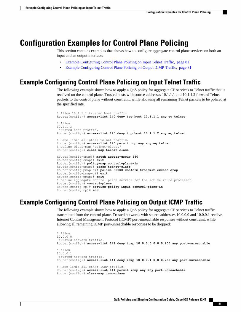
Configuration Examples for Control Plane PolicingThis section contains examples that shows how to configure aggregate control plane services on both aninput and an output interface:
• Example Configuring Control Plane Policing on Input Telnet Traffic, page 81• Example Configuring Control Plane Policing on Output ICMP Traffic, page 81
Example Configuring Control Plane Policing on Input Telnet TrafficThe following example shows how to apply a QoS policy for aggregate CP services to Telnet traffic that isreceived on the control plane. Trusted hosts with source addresses 10.1.1.1 and 10.1.1.2 forward Telnetpackets to the control plane without constraint, while allowing all remaining Telnet packets to be policed atthe specified rate.
! Allow 10.1.1.1 trusted host traffic.Router(config)# access-list 140 deny tcp host 10.1.1.1 any eq telnet ! Allow 10.1.1.2 trusted host traffic. Router(config)# access-list 140 deny tcp host 10.1.1.2 any eq telnet ! Rate-limit all other Telnet traffic.Router(config)# access-list 140 permit tcp any any eq telnet! Define class-map "telnet-class."Router(config)# class-map telnet-class Router(config-cmap)# match access-group 140Router(config-cmap)# exitRouter(config)# policy-map control-plane-inRouter(config-pmap)# class telnet-classRouter(config-pmap-c)# police 80000 conform transmit exceed dropRouter(config-pmap-c)# exitRouter(config-pmap)# exit! Define aggregate control plane service for the active route processor.Router(config)# control-planeRouter(config-cp)# service-policy input control-plane-inRouter(config-cp)# end
Example Configuring Control Plane Policing on Output ICMP TrafficThe following example shows how to apply a QoS policy for aggregate CP services to Telnet traffictransmitted from the control plane. Trusted networks with source addresses 10.0.0.0 and 10.0.0.1 receiveInternet Control Management Protocol (ICMP) port-unreachable responses without constraint, whileallowing all remaining ICMP port-unreachable responses to be dropped:
! Allow 10.0.0.0 trusted network traffic.Router(config)# access-list 141 deny icmp 10.0.0.0 0.0.0.255 any port-unreachable ! Allow 10.0.0.1 trusted network traffic.Router(config)# access-list 141 deny icmp 10.0.0.1 0.0.0.255 any port-unreachable ! Rate-limit all other ICMP traffic. Router(config)# access-list 141 permit icmp any any port-unreachableRouter(config)# class-map icmp-class
Example Configuring Control Plane Policing on Input Telnet TrafficConfiguration Examples for Control Plane Policing
QoS: Policing and Shaping Configuration Guide, Cisco IOS Release 12.4T 81
Router(config-cmap)# match access-group 141Router(config-cmap)# exitRouter(config)# policy-map control-plane-out! Drop all traffic that matches the class "icmp-class."Router(config-pmap)# class icmp-classRouter(config-pmap-c)# dropRouter(config-pmap-c)# exitRouter(config-pmap)# exitRouter(config)# control-plane! Define aggregate control plane service for the active route processor.Router(config-cp)# service-policy output control-plane-outRouter(config-cp)# end
Additional ReferencesThe following sections provide references related to the Control Plane Policing feature.
Related Documents
Related Topic Document Title
QoS commands: complete command syntax,command modes, command history, defaults, usageguidelines, and examples
Cisco IOS Quality of Service Solutions CommandReference
QoS features overview "Quality of Service Overview" module
MQC "Applying QoS Features Using the MQC" module
Security features overview "Control Plane Security Overview" module in theCisco IOS Security Configuration Guide: Securingthe Control Plane
Control plane policing in Cisco IOS Release12.2(18)SXD1 and later releases
For Catalyst 6500 series switches, see the"Configuring Control Plane Policing (CoPP)"module.
For Cisco 7600 series routers, see the "ConfiguringDenial of Service Protection" module.
Enhanced RP protection "ACL IP Options Selective Drop" module
Standards
Standard Title
No new or modified standards are supported by thisfeature, and support for existing standards has notbeen modified by this feature.
--
Control Plane Policing Additional References
QoS: Policing and Shaping Configuration Guide, Cisco IOS Release 12.4T82
MIBs
MIB MIBs Link
• CISCO-CLASS-BASED-QOS-MIB
Note Supported only in Cisco IOS Release12.3(7)T.
To locate and download MIBs for selectedplatforms, Cisco IOS releases, and feature sets, useCisco MIB Locator, found at the following URL:
http://www.cisco.com/go/mibs
RFCs
RFC Title
No new or modified RFCs are supported by thisfeature, and support for existing RFCs has not beenmodified by this feature.
--
Technical Assistance
Description Link
The Cisco Support and Documentation websiteprovides online resources to downloaddocumentation, software, and tools. Use theseresources to install and configure the software andto troubleshoot and resolve technical issues withCisco products and technologies. Access to mosttools on the Cisco Support and Documentationwebsite requires a Cisco.com user ID andpassword.
http://www.cisco.com/cisco/web/support/index.html
Feature Information for Control Plane PolicingThe following table provides release information about the feature or features described in this module.This table lists only the software release that introduced support for a given feature in a given softwarerelease train. Unless noted otherwise, subsequent releases of that software release train also support thatfeature.
Use Cisco Feature Navigator to find information about platform support and Cisco software image support.To access Cisco Feature Navigator, go to www.cisco.com/go/cfn. An account on Cisco.com is not required.
Control Plane PolicingFeature Information for Control Plane Policing
QoS: Policing and Shaping Configuration Guide, Cisco IOS Release 12.4T 83

Table 3 Feature Information for Control Plane Policing
Feature Name Releases Feature Information
Control Plane Policing 12.2(18)S 12.3(4)T 12.3(7)T12.0(29)S 12.2(18)SXD112.0(30)S 12.2(27)SBC12.0(32)S 12.3(31)SB2 15.0(1)S
The Control Plane Policingfeature allows users to configurea quality of service (QoS) filterthat manages the traffic flow ofcontrol plane packets to protectthe control plane of Cisco IOSrouters and switches againstreconnaissance and denial-of-service (DoS) attacks.
For Release 12.2(18)S, thisfeature was introduced.
For Release 12.3(4)T, this featurewas integrated into Cisco IOSRelease 12.3(4)T, and the outputrate-limiting (silent modeoperation) feature was added.
For Release 12.3(7)T, theCISCO-CLASS-BASED-QOS-MIB was extended to managecontrol plane QoS policies, andthe police ratecommand wasintroduced to support trafficpolicing on the basis of packetsper second for control planetraffic.
For Release 12.0(29)S, thisfeature was integrated into CiscoIOS Release 12.0(29)S.
For Release 12.2(18)SXD1, thisfeature was integrated into CiscoIOS Release 12.2(18)SXD1.
For Release 12.0(30)S, thisfeature was modified to includesupport for distributed controlplane services on the Cisco 12000series Internet router.
For Release 12.2(27)SBC, thisfeature was integrated into CiscoIOS Release 12.2(27)SBC.
For Release 12.0(32)S, thisfeature was modified to includesupport for aggregate controlplane services on the Cisco 10720Internet router.
For Release 12.3(31)SB2, thisfeature was implemented on the
Control Plane Policing Feature Information for Control Plane Policing
QoS: Policing and Shaping Configuration Guide, Cisco IOS Release 12.4T84
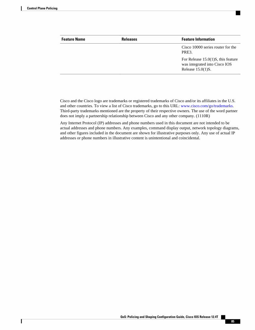
Feature Name Releases Feature Information
Cisco 10000 series router for thePRE3.
For Release 15.0(1)S, this featurewas integrated into Cisco IOSRelease 15.0(1)S.
Cisco and the Cisco logo are trademarks or registered trademarks of Cisco and/or its affiliates in the U.S.and other countries. To view a list of Cisco trademarks, go to this URL: www.cisco.com/go/trademarks.Third-party trademarks mentioned are the property of their respective owners. The use of the word partnerdoes not imply a partnership relationship between Cisco and any other company. (1110R)
Any Internet Protocol (IP) addresses and phone numbers used in this document are not intended to beactual addresses and phone numbers. Any examples, command display output, network topology diagrams,and other figures included in the document are shown for illustrative purposes only. Any use of actual IPaddresses or phone numbers in illustrative content is unintentional and coincidental.
Control Plane Policing
QoS: Policing and Shaping Configuration Guide, Cisco IOS Release 12.4T 85
Example Configuring Control Plane Policing on Output ICMP Traffic
QoS: Policing and Shaping Configuration Guide, Cisco IOS Release 12.4T86

Control Plane Protection
The Control Plane Protection feature is an extension of the policing functionality provided by the existingControl-Plane Policing feature. The Control-Plane Policing feature allows Quality of Service (QoS)policing of aggregate control-plane traffic destined to the route processor. The Control Plane Protectionfeature extends this policing functionality by allowing finer policing granularity.
The functionality added with Control Plane Protection includes a traffic classifier, which intercepts trafficand classifies it into three control-plane categories. New port-filtering and queue-thresholding featureshave also been added. The port-filtering feature provides for policing of packets going to closed ornonlistened TCP/UDP ports, while queue-thresholding limits the number of packets for a specifiedprotocol that will be allowed in the control-plane IP input queue.
• Finding Feature Information, page 87• Prerequisites for Control Plane Protection, page 87• Restrictions for Control Plane Protection, page 88• Information About Control Plane Protection, page 89• How to Configure Control Plane Protection, page 92• Additional References, page 109• Feature Information for Control Plane Protection, page 110
Finding Feature InformationYour software release may not support all the features documented in this module. For the latest featureinformation and caveats, see the release notes for your platform and software release. To find informationabout the features documented in this module, and to see a list of the releases in which each feature issupported, see the Feature Information Table at the end of this document.
Use Cisco Feature Navigator to find information about platform support and Cisco software image support.To access Cisco Feature Navigator, go to www.cisco.com/go/cfn. An account on Cisco.com is not required.
Prerequisites for Control Plane Protection• You understand the principles of Control-Plane Policing and how to classify control-plane traffic.• You understand the concepts and general configuration procedure (class map and policy map) for
applying QoS policies on a router.
For information about control plane policing and its capabilities, see the “Control Plane Policing” module.
QoS: Policing and Shaping Configuration Guide, Cisco IOS Release 12.4T 87

For information about Cisco IOS QoS and the procedure for configuring QoS in your network using theModular Quality of Service (QoS) Command-Line Interface (CLI) (MQC), see the QoS: Modular QoS:Command-Line Interface Configuration Guide.
Restrictions for Control Plane ProtectionControl Plane Protection for IPv4
Control Plane Protection is restricted to IPv4 input path only.
No Support for Direct ACL Configuration
The current release of Control Plane Protection does not support direct access control list (ACL)configuration in the control-plane subinterfaces, but rather can be configured using Modular QoS CLI(MQC) policies.
Requires CEF
Control Plane Protection depends on Cisco Express Forwarding (CEF) for IP packet redirection. If youdisable CEF globally, this will remove all active protect and policing policies configured on the control-plane subinterfaces. Aggregate control-plane interface policies will continue to function as normal.
Control-plane Feature Policy Restriction
Policies applicable on the control-plane host subinterface are subject to the following restrictions:
• The port-filter feature policy supports only TCP/UDP-based protocols.• The queue-thresholding feature policy supports only TCP/UDP-based protocols.
No Support for Distributed or Hardware Switching Platforms
This release does not provide support for distributed or hardware switching platforms.
Control-plane IP Traffic Classification Restrictions
The control-plane host subinterface only supports TCP/UDP-based host traffic. All IP packets entering thecontrol-plane matching any of the following conditions are not classified any further and are redirected tothe cef-exception subinterface:
• IP Packets with IP options.• IP Packets with TTL less than or equal to 1.
Protocols Auto-detected by the Port-filter
Some Cisco IOS TCP/UDP-based services, when configured, may not be auto-detected by the port-filter.That is, they do not get listed under the show control-plane host open ports output and they are notclassified as an open port. This type of port must be manually added to the active port-filter class-map to beunblocked.
Control Plane Protection Restrictions for Control Plane Protection
QoS: Policing and Shaping Configuration Guide, Cisco IOS Release 12.4T88

Control-plane Policing Subinterface Restrictions
There are no restrictions on existing aggregate control-plane policing policies. New control-plane policingpolicies that are configured on host subinterface will not process ARP traffic since ARP traffic is processedat the cef-exception and aggregate interfaces.
Information About Control Plane Protection• Benefits of Control Plane Protection, page 89
• Control Plane Protection Architecture, page 90
• Control-plane Interface and Subinterfaces, page 90
• Control-plane Port-filtering, page 91
• Control-plane Queue-thresholding, page 91
• Aggregate Control-plane Services, page 92
• Control Plane Protection Configuration, page 92
Benefits of Control Plane ProtectionConfiguring the Control Plane Protection feature on your Cisco router provides the following benefits:
• Extends protection against DoS attacks at infrastructure routers by providing mechanism for finerpolicing granularity for control-plane traffic that allows you to rate-limit each type individually.
• Provides a mechanism for early dropping of packets that are directed to closed or nonlistened IOSTCP/UDP ports.
• Provides ability to limit protocol queue usage such that no single protocol flood can overwhelm theinput interface.
• Provides QoS control for packets that are destined to the control-plane of Cisco routers.• Provides ease of configuration for control plane policies using MQC Infrastructure.• Provides better platform reliability, security and availability.• Provides dedicated control-plane subinterface for aggregate, host, transit and cef-exception control-
plane traffic processing.• Is highly flexible: permit, deny, rate-limit.• Provides CPU protection so it can be used for important jobs, such as routing.
Benefits of Control Plane ProtectionInformation About Control Plane Protection
QoS: Policing and Shaping Configuration Guide, Cisco IOS Release 12.4T 89

Control Plane Protection ArchitectureThe figure below shows control-plane architecture with the Control Plane Protection feature.
Figure 4 Control-plane Architecture with Control Plane Protection
The following sections describe the components of the Control Plane Protections feature.
Control-plane Interface and SubinterfacesControl Plane Policing (CoPP) introduced the concept of early rate-limiting protocol specific trafficdestined to the processor by applying QoS policies to the aggregate control-plane interface. Control PlaneProtection extends this control plane functionality by providing three additional control-plane subinterfacesunder the top-level (aggregate) control-plane interface. Each subinterface receives and processes a specifictype of control-plane traffic. The three subinterfaces are:
• Control-plane host subinterface . This interface receives all control-plane IP traffic that is directlydestined for one of the router interfaces. Examples of control-plane host IP traffic include tunneltermination traffic, management traffic or routing protocols such as SSH, SNMP, BGP, OSPF, andEIGRP. All host traffic terminates on and is processed by the router. Most control plane protectionfeatures and policies operate strictly on the control-plane host subinterface. Since most critical routercontrol plane services, such as routing protocols and management traffic, is received on the control-plane host subinterface, it is critical to protect this traffic through policing and protection policies.CoPP, port-filtering and per-protocol queue thresholding protection features can be applied on thecontrol-plane host subinterface.
Control Plane Protection Architecture Information About Control Plane Protection
QoS: Policing and Shaping Configuration Guide, Cisco IOS Release 12.4T90

Note Non-IP based Layer 2 protocol packets such as ARP or CDP do not fall within the control-plane hostsubinterface. These packets are currently classified in the control-plane CEF-exception subinterface traffic.
• Control-plane transit subinterface . This subinterface receives all control-plane IP traffic that issoftware switched by the route processor. This means packets that are not directly destined to therouter itself but rather traffic traversing through the router. Nonterminating tunnels handled by therouter is an example of this type of control-plane traffic. Control Plane Protection allows specificaggregate policing of all traffic received at this subinterface.
• Control-plane CEF-exception subinterface . This control-plane subinterface receives all traffic thatis either redirected as a result of a configured input feature in the CEF packet forwarding path forprocess switching or directly enqueued in the control plane input queue by the interface driver (i.e.ARP, L2 Keepalives and all non-IP host traffic). Control Plane Protection allows specific aggregatepolicing of this type of control plane traffic.
QoS policies attached on any of the control-plane interfaces or subinterfaces execute at interrupt level priorto packets being enqueued to the IP input queue and sent to the processor.
The transit and CEF-exception control plane subinterfaces exist in parallel to the control plane hostsubinterface. This release of Control Plane Protection allows for rate-limiting policies to be configured onthese paths as Control Plane Policing extensions. The port-filtering and per-protocol queue thresholdingfeatures are not available on these control-plane subinterfaces.
All protection features in the control plane are implemented as MQC policies that operate using the controlplane class-maps and policy-maps. New class-map and policy-map types have been created for the controlplane port-filter and per-protocol queue-threshold features.
Control-plane Port-filteringThe control-plane Port-filtering feature enhances control plane protection by providing for early droppingof packets directed toward closed or nonlistened IOS TCP/UDP ports on the router. The port-filter featurepolicy can be applied only to the control-plane host subinterface.
The port-filter maintains a global database of all open TCP and UDP ports on the router, including randomephemeral ports created by applications. The port database is dynamically populated with entries providedby the registered applications as they start listening on their advertised ports either by configuration of anapplication (that is SNMP) or initiation of an application (that is, TFTP transfer). An MQC class-map usingthe list of open ports can be configured and a simple drop policy can be applied to drop all packets destinedto closed or nonlistened ports. Port-filter class-maps also support direct match of any user configuredTCP/UDP port numbers.
Control-plane Queue-thresholdingControl-plane protocol Queue-thresholding feature provides a mechanism for limiting the number ofunprocessed packets a protocol can have at process-level. This feature can only be applied to the control-plane host subinterface. The intent of this feature is to prevent the input queue from being overwhelmed byany single protocol traffic. Per-protocol thresholding follows a protocol charge model. Each protocol'squeue usage is limited such that no single mis-behaving protocol process can jam the interface hold queue.In this release, only a subset of TCP/UDP protocols can be configured for thresholding. Non-IP and Layer2 protocols such as ARP and CDP cannot be configured. You can set queue limits for the followingprotocols:
• bgp—Border Gateway Protocol
Control-plane Port-filteringInformation About Control Plane Protection
QoS: Policing and Shaping Configuration Guide, Cisco IOS Release 12.4T 91

• dns—Domain Name Server lookup• ftp—File Transfer Protocol• http—World Wide Web traffic• igmp— Internet Group Management Protocol• snmp—Simple Network Management Protocol• ssh—Secure Shell Protocol• syslog—Syslog Server• telnet—Telnet• tftp—Trivial File Transfer Protocol• host-protocols—A wild card for all TCP/UDP protocol ports open on the router not specifically
matched/configured
Aggregate Control-plane ServicesControl-plane Policing is an existing Cisco IOS feature that allows QoS policing of aggregate control-planetraffic destined to the route processor. The Control Plane Protection feature enhances protection for therouter’s control-plane by providing finer granularity of policing of traffic destined to the router’s processorentering through any of the three control-plane subinterfaces. The CoPP feature is intended to be the firstControl Plane Protection feature encountered by packets before any other features/policies. Existing(aggregate) Control-plane Policing policies will not be affected when the Control Plane Protectionfunctionality is enabled. The aggregate Control-plane Policing policy will be applied on all control-planetraffic types. However, Control Plane Protection allows for additional and/or separate Control-planePolicing policies to be configured and applied on the different types of control-plane subinterfaces (host,transit, CEF-exception).
Control Plane Protection ConfigurationThe CLI for control-plane (introduced with the Control Plane Policing feature) has been extended to allowfor CoPP policies to be applied to individual control-plane subinterfaces (host, transit, CEF-exception). Thecommand syntax for creating CoPP Service Policies remains the same. In addition, the MQC class-map andpolicy-map CLI was modified to allow for additional types. The port-filter and queue-threshold policyfeatures available in the host subinterface uses these new class-map and policy-map “types”.
CoPP leverages MQC to define traffic classification criteria and to specify configurable policy actions forthe classified traffic. Traffic of interest must first be identified via class-maps, which are used to definepackets for a particular traffic class. Once classified, enforceable policy actions for the identified traffic arecreated with policy-maps. The control-plane global command allows the control-plane service policies tobe attached to the aggregate control-plane interface itself.
The CLI for configuring Control-plane Policing policies on the new control-plane subinterfaces remainsbasically the same as the CLI introduced for Control-plane Policing. The only difference is in how youapply or attach the CoPP policy to the different control-plane subinterfaces.
How to Configure Control Plane Protection• Defining Packet Classification Criteria for CoPP, page 93• Defining a CoPP Service Policy, page 94• Entering Control Plane Configuration Mode, page 96• Applying CoPP Service Policy, page 97
Aggregate Control-plane Services How to Configure Control Plane Protection
QoS: Policing and Shaping Configuration Guide, Cisco IOS Release 12.4T92
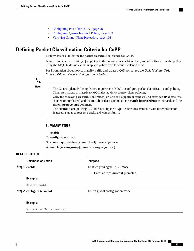
• Configuring Port-filter Policy, page 98
• Configuring Queue-threshold Policy, page 103
• Verifying Control Plane Protection, page 108
Defining Packet Classification Criteria for CoPPPerform this task to define the packet classification criteria for CoPP.
Before you attach an existing QoS policy to the control-plane subinterface, you must first create the policyusing the MQC to define a class map and policy map for control-plane traffic.
For information about how to classify traffic and create a QoS policy, see the QoS: Modular QoS:Command-Line Interface Configuration Guide.
Note• The Control-plane Policing feature requires the MQC to configure packet classification and policing.
Thus, restrictions that apply to MQC also apply to control-plane policing.• Only the following classification (match) criteria are supported: standard and extended IP access lists
(named or numbered) and the match ip dscp command, the match ip precedence command, and thematch protocol arp command.
• The control-plane policing CLI does not support “type” extensions available with other protectionfeatures. This is to preserve backward-compatibility.
SUMMARY STEPS
1. enable
2. configure terminal
3. class-map [match-any | match-all] class-map-name
4. match {access-group | name access-group-name}
DETAILED STEPS
Command or Action Purpose
Step 1 enable
Example:
Router> enable
Enables privileged EXEC mode.
• Enter your password if prompted.
Step 2 configure terminal
Example:
Router# configure terminal
Enters global configuration mode.
Defining Packet Classification Criteria for CoPPHow to Configure Control Plane Protection
QoS: Policing and Shaping Configuration Guide, Cisco IOS Release 12.4T 93

Command or Action Purpose
Step 3 class-map [match-any | match-all] class-map-name
Example:
Router(config)# class-map match-any control-plane-class
Enables class map global configuration command mode used to create atraffic class.
• match-any —Specifies that one of the match criterion must be metfor traffic entering the traffic class to be classified as part of thetraffic class.
• match-all —Specifies that all match criterion must be met for trafficentering the traffic class to be classified as part of the traffic class.
• class-map-name —Specifies the user-defined name of the trafficclass. Names can be a maximum of 40 alphanumeric characters.
Step 4 match {access-group | name access-group-name}
Example:
Router(config-cmap)# match access-group name cpp-igp-acl
Specifies the match criteria for the class-map.
Defining a CoPP Service PolicyTo define a service policy, use the policy-map global configuration command to specify the service policyname, and use the configuration commands to associate a traffic class that was configured with the class-map command, with the QoS action. The traffic class is associated with the service policy when the classcommand is used. You must issue the class command after entering policy-map configuration mode. Afterentering the class command, you are automatically in policy-map class configuration mode.
For information about how to classify traffic and create a QoS policy, see the QoS: Modular QoS:Command-Line Interface Configuration Guide.
Note• Platform-specific restrictions, if any, are checked when the service policy is applied to the control-
plane interface.• The Control-plane Policing feature requires the modular QoS command-line interface (CLI) (MQC) to
configure packet classification and policing. Thus, restrictions that apply to MQC also apply tocontrol-plane policing. Also, only two MQC actions are supported in policy maps - police and drop.
• Support for output policing is available only in Cisco IOS Release 12.3(4)T and later T-train releases,and only on the aggregate control-plane interface. Only input policing is available on the new control-plane host, transit and CEF-exception subinterfaces. (Note that output policing does not provide anyperformance benefits. It simply controls the information that is leaving the device.)
Defining a CoPP Service Policy How to Configure Control Plane Protection
QoS: Policing and Shaping Configuration Guide, Cisco IOS Release 12.4T94

SUMMARY STEPS
1. enable
2. configure terminal
3. policy-map policy-map-name
4. class class-name
5. police rate [burst-normal] [burst-max] conform-action action exceed-action action [violate-actionaction]
DETAILED STEPS
Command or Action Purpose
Step 1 enable
Example:
Router> enable
Enables privileged EXEC mode.
• Enter your password if prompted.
Step 2 configure terminal
Example:
Router# configure terminal
Enters global configuration mode.
Step 3 policy-map policy-map-name
Example:
Router(config)# policy-map control-plane-policy
Enters policy map configuration mode to define a policy.
• policy-map-name —Name of a service policy map. The name can be amaximum of 40 alphanumeric characters.
Step 4 class class-name
Example:
Router(config-pmap)# class control-plane-class
Enters class map configuration mode, which is used to associate a servicepolicy with a class.
• class-name —Name of a service policy class. The name can be amaximum of 40 alphanumeric characters.
Control Plane ProtectionHow to Configure Control Plane Protection
QoS: Policing and Shaping Configuration Guide, Cisco IOS Release 12.4T 95

Command or Action Purpose
Step 5 police rate [burst-normal] [burst-max]conform-action action exceed-actionaction [violate-action action]
Example:
Router(config-pmap-c)# police rate 50000 pps conform-action transmit exceed-action drop
To configure traffic policing, use the police command in policy-map classconfiguration mode or policy-map class police configuration mode.
• rate —Specifies the police rate. If the police rate is specified in pps, thevalid value range is 1 to 2000000. If the police rate is specified in bps, thevalid range of values is 8000 to 10000000000.
• pps —(Optional) Packets per second (pps) will be used to determine therate at which traffic is policed.
• conform-action action —Action to take on packets that conform to therate limit.
• exceed-action action —Action to take on packets that exceed the ratelimit.
Entering Control Plane Configuration ModeAfter you have created a class of traffic and defined the service policy for the control-plane, apply thepolicy to either the aggregate control-plane interface or one of the subinterfaces.
Note• Platform-specific restrictions, if any, are checked when the service policy is applied to the control-
plane interface.• Support for output policing is available only in Cisco IOS Release 12.3(4)T and later T-train releases,
and only on the aggregate control-plane interface. Only input policing is available on the new control-plane host, transit and CEF-exception subinterfaces. (Note that output policing does not provide anyperformance benefits. It simply controls the information that is leaving the device.)
SUMMARY STEPS
1. enable
2. configure terminal
3. control-plane [host | transit | cef-exception]
DETAILED STEPS
Command or Action Purpose
Step 1 enable
Example:
Router> enable
Enables privileged EXEC mode.
• Enter your password if prompted.
Entering Control Plane Configuration Mode How to Configure Control Plane Protection
QoS: Policing and Shaping Configuration Guide, Cisco IOS Release 12.4T96

Command or Action Purpose
Step 2 configure terminal
Example:
Router# configure terminal
Enters global configuration mode.
Step 3 control-plane [host | transit | cef-exception]
Example:
Router(config)# control-plane
Enters control-plane configuration mode to attach a QoS policy thatmanages CP traffic to specified control-plane subinterface:
• host —enters control-plane host subinterface configuration mode.• transit —enters control-plane transit subinterface configuration mode.• cef-exception —enters control-plane cef-exception subinterface
configuration mode.
Applying CoPP Service PolicyPerform this task to apply CoPP service policies to a control-plane interface.
Before you attach an existing QoS policy to the control-plane, you must first create the policy by usingMQC to define a class map and policy map for control-plane traffic.
For information about how to classify traffic and create a QoS policy, see the QoS: Modular QoS:Command-Line Interface Configuration Guide.
Note• Platform-specific restrictions, if any, are checked when the service policy is applied to the control-
plane interface.• Support for output policing is available only in Cisco IOS Release 12.3(4)T and later T-train releases,
and only on the aggregate control-plane interface. Only input policing is available on the new control-plane host, transit and CEF-exception subinterfaces. (Note that output policing does not provide anyperformance benefits. It simply controls the information that is leaving the device.)
SUMMARY STEPS
1. enable
2. configure terminal
3. control-plane [host | transit | cef-exception]
4. service-policy {input | output} policy-map-name
Applying CoPP Service PolicyHow to Configure Control Plane Protection
QoS: Policing and Shaping Configuration Guide, Cisco IOS Release 12.4T 97
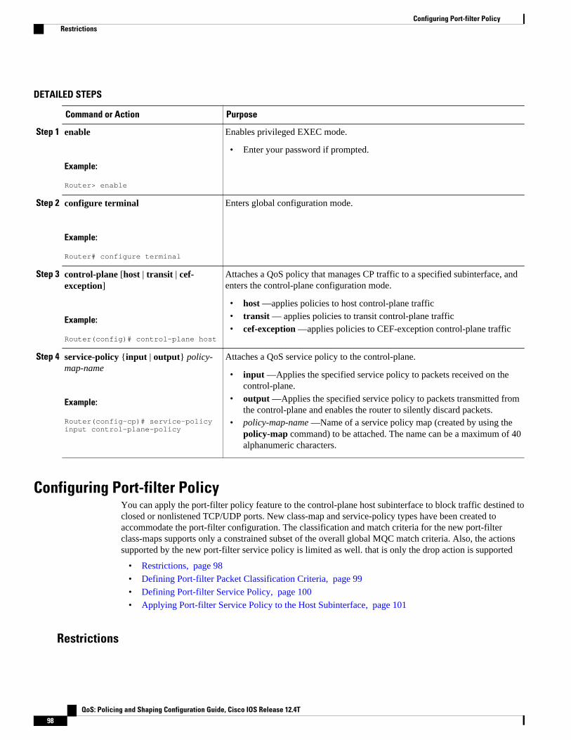
DETAILED STEPS
Command or Action Purpose
Step 1 enable
Example:
Router> enable
Enables privileged EXEC mode.
• Enter your password if prompted.
Step 2 configure terminal
Example:
Router# configure terminal
Enters global configuration mode.
Step 3 control-plane [host | transit | cef-exception]
Example:
Router(config)# control-plane host
Attaches a QoS policy that manages CP traffic to a specified subinterface, andenters the control-plane configuration mode.
• host —applies policies to host control-plane traffic• transit — applies policies to transit control-plane traffic• cef-exception —applies policies to CEF-exception control-plane traffic
Step 4 service-policy {input | output} policy-map-name
Example:
Router(config-cp)# service-policy input control-plane-policy
Attaches a QoS service policy to the control-plane.
• input —Applies the specified service policy to packets received on thecontrol-plane.
• output —Applies the specified service policy to packets transmitted fromthe control-plane and enables the router to silently discard packets.
• policy-map-name —Name of a service policy map (created by using thepolicy-map command) to be attached. The name can be a maximum of 40alphanumeric characters.
Configuring Port-filter PolicyYou can apply the port-filter policy feature to the control-plane host subinterface to block traffic destined toclosed or nonlistened TCP/UDP ports. New class-map and service-policy types have been created toaccommodate the port-filter configuration. The classification and match criteria for the new port-filterclass-maps supports only a constrained subset of the overall global MQC match criteria. Also, the actionssupported by the new port-filter service policy is limited as well. that is only the drop action is supported
• Restrictions, page 98
• Defining Port-filter Packet Classification Criteria, page 99
• Defining Port-filter Service Policy, page 100
• Applying Port-filter Service Policy to the Host Subinterface, page 101
Restrictions
Configuring Port-filter Policy Restrictions
QoS: Policing and Shaping Configuration Guide, Cisco IOS Release 12.4T98
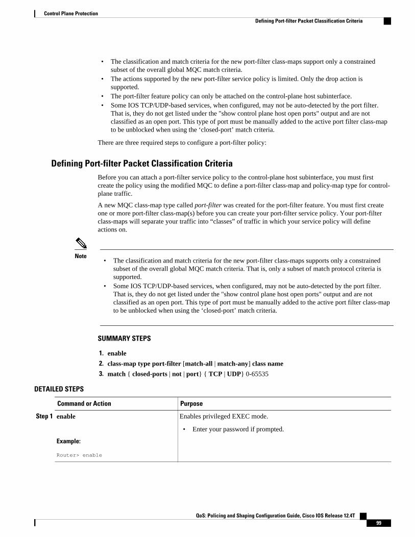
• The classification and match criteria for the new port-filter class-maps support only a constrainedsubset of the overall global MQC match criteria.
• The actions supported by the new port-filter service policy is limited. Only the drop action issupported.
• The port-filter feature policy can only be attached on the control-plane host subinterface.• Some IOS TCP/UDP-based services, when configured, may not be auto-detected by the port filter.
That is, they do not get listed under the "show control plane host open ports" output and are notclassified as an open port. This type of port must be manually added to the active port filter class-mapto be unblocked when using the ‘closed-port’ match criteria.
There are three required steps to configure a port-filter policy:
Defining Port-filter Packet Classification CriteriaBefore you can attach a port-filter service policy to the control-plane host subinterface, you must firstcreate the policy using the modified MQC to define a port-filter class-map and policy-map type for control-plane traffic.
A new MQC class-map type called port-filter was created for the port-filter feature. You must first createone or more port-filter class-map(s) before you can create your port-filter service policy. Your port-filterclass-maps will separate your traffic into “classes” of traffic in which your service policy will defineactions on.
Note• The classification and match criteria for the new port-filter class-maps supports only a constrained
subset of the overall global MQC match criteria. That is, only a subset of match protocol criteria issupported.
• Some IOS TCP/UDP-based services, when configured, may not be auto-detected by the port filter.That is, they do not get listed under the "show control plane host open ports" output and are notclassified as an open port. This type of port must be manually added to the active port filter class-mapto be unblocked when using the ‘closed-port’ match criteria.
SUMMARY STEPS
1. enable
2. class-map type port-filter [match-all | match-any] class name
3. match { closed-ports | not | port} { TCP | UDP} 0-65535
DETAILED STEPS
Command or Action Purpose
Step 1 enable
Example:
Router> enable
Enables privileged EXEC mode.
• Enter your password if prompted.
Control Plane ProtectionDefining Port-filter Packet Classification Criteria
QoS: Policing and Shaping Configuration Guide, Cisco IOS Release 12.4T 99
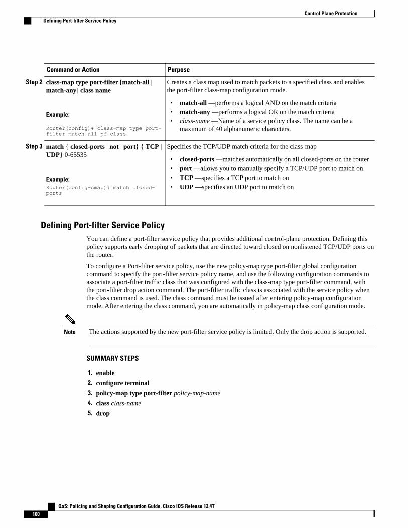
Command or Action Purpose
Step 2 class-map type port-filter [match-all |match-any] class name
Example:
Router(config)# class-map type port-filter match-all pf-class
Creates a class map used to match packets to a specified class and enablesthe port-filter class-map configuration mode.
• match-all —performs a logical AND on the match criteria• match-any —performs a logical OR on the match criteria• class-name —Name of a service policy class. The name can be a
maximum of 40 alphanumeric characters.
Step 3 match { closed-ports | not | port} { TCP |UDP} 0-65535
Example:Router(config-cmap)# match closed-ports
Specifies the TCP/UDP match criteria for the class-map
• closed-ports —matches automatically on all closed-ports on the router• port —allows you to manually specify a TCP/UDP port to match on.• TCP —specifies a TCP port to match on• UDP —specifies an UDP port to match on
Defining Port-filter Service PolicyYou can define a port-filter service policy that provides additional control-plane protection. Defining thispolicy supports early dropping of packets that are directed toward closed on nonlistened TCP/UDP ports onthe router.
To configure a Port-filter service policy, use the new policy-map type port-filter global configurationcommand to specify the port-filter service policy name, and use the following configuration commands toassociate a port-filter traffic class that was configured with the class-map type port-filter command, withthe port-filter drop action command. The port-filter traffic class is associated with the service policy whenthe class command is used. The class command must be issued after entering policy-map configurationmode. After entering the class command, you are automatically in policy-map class configuration mode.
Note The actions supported by the new port-filter service policy is limited. Only the drop action is supported.
SUMMARY STEPS
1. enable
2. configure terminal
3. policy-map type port-filter policy-map-name
4. class class-name
5. drop
Control Plane Protection Defining Port-filter Service Policy
QoS: Policing and Shaping Configuration Guide, Cisco IOS Release 12.4T100
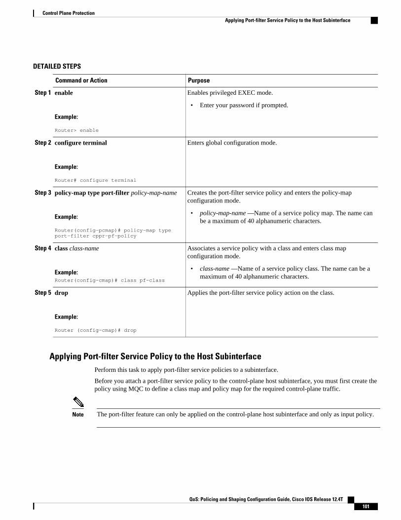
DETAILED STEPS
Command or Action Purpose
Step 1 enable
Example:
Router> enable
Enables privileged EXEC mode.
• Enter your password if prompted.
Step 2 configure terminal
Example:
Router# configure terminal
Enters global configuration mode.
Step 3 policy-map type port-filter policy-map-name
Example:
Router(config-pcmap)# policy-map type port-filter cppr-pf-policy
Creates the port-filter service policy and enters the policy-mapconfiguration mode.
• policy-map-name —Name of a service policy map. The name canbe a maximum of 40 alphanumeric characters.
Step 4 class class-name
Example:Router(config-cmap)# class pf-class
Associates a service policy with a class and enters class mapconfiguration mode.
• class-name —Name of a service policy class. The name can be amaximum of 40 alphanumeric characters.
Step 5 drop
Example:
Router (config-cmap)# drop
Applies the port-filter service policy action on the class.
Applying Port-filter Service Policy to the Host SubinterfacePerform this task to apply port-filter service policies to a subinterface.
Before you attach a port-filter service policy to the control-plane host subinterface, you must first create thepolicy using MQC to define a class map and policy map for the required control-plane traffic.
Note The port-filter feature can only be applied on the control-plane host subinterface and only as input policy.
Control Plane ProtectionApplying Port-filter Service Policy to the Host Subinterface
QoS: Policing and Shaping Configuration Guide, Cisco IOS Release 12.4T 101
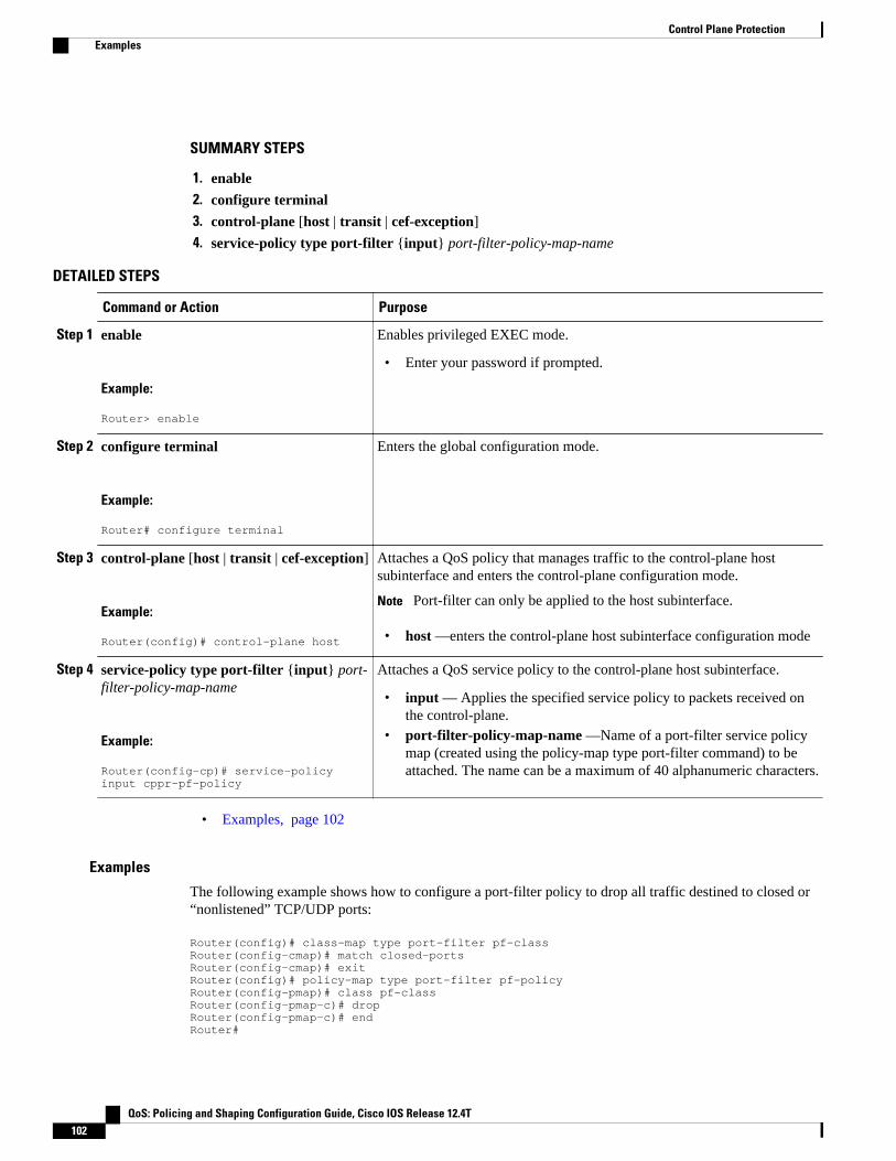
SUMMARY STEPS
1. enable
2. configure terminal
3. control-plane [host | transit | cef-exception]
4. service-policy type port-filter {input} port-filter-policy-map-name
DETAILED STEPS
Command or Action Purpose
Step 1 enable
Example:
Router> enable
Enables privileged EXEC mode.
• Enter your password if prompted.
Step 2 configure terminal
Example:
Router# configure terminal
Enters the global configuration mode.
Step 3 control-plane [host | transit | cef-exception]
Example:
Router(config)# control-plane host
Attaches a QoS policy that manages traffic to the control-plane hostsubinterface and enters the control-plane configuration mode.
Note Port-filter can only be applied to the host subinterface.
• host —enters the control-plane host subinterface configuration mode
Step 4 service-policy type port-filter {input} port-filter-policy-map-name
Example:
Router(config-cp)# service-policy input cppr-pf-policy
Attaches a QoS service policy to the control-plane host subinterface.
• input — Applies the specified service policy to packets received onthe control-plane.
• port-filter-policy-map-name —Name of a port-filter service policymap (created using the policy-map type port-filter command) to beattached. The name can be a maximum of 40 alphanumeric characters.
• Examples, page 102
Examples
The following example shows how to configure a port-filter policy to drop all traffic destined to closed or“nonlistened” TCP/UDP ports:
Router(config)# class-map type port-filter pf-classRouter(config-cmap)# match closed-portsRouter(config-cmap)# exitRouter(config)# policy-map type port-filter pf-policyRouter(config-pmap)# class pf-classRouter(config-pmap-c)# dropRouter(config-pmap-c)# end Router#
Control Plane Protection Examples
QoS: Policing and Shaping Configuration Guide, Cisco IOS Release 12.4T102

The following example shows how to configure a port-filter policy to drop all traffic destined to closed or“nonlistened” ports except NTP.
Router(config)# class-map type port-filter pf-classRouter(config-cmap)# match not port udp 123Router(config-cmap)# match closed-portsRouter(config-cmap)# exitRouter(config)# policy-map type port-filter pf-policyRouter(config-pmap)# class pf-classRouter(config-pmap-c)# dropRouter(config-pmap-c)# endRouter#
Configuring Queue-threshold PolicyThe Control Plane Protection feature includes a new queue-threshold policy feature that can be applied tothe control-plane host subinterface. The queue-threshold feature allows you to limit the number of packetsfor a given higher level protocol allowed in the control-plane IP input queue. Much like the port-filterfeature, new class-map and policy-map types have been created to accommodate the queue-thresholdfeature. As with the port-filter feature, the queue-threshold feature supports a very specific class-map andpolicy-map capabilities.
• Restrictions, page 103
• Defining Queue-threshold Packet Classification Criteria, page 103
• Defining a Queue-threshold Service Policy, page 105
• Applying a Queue-threshold Policy to the Host Subinterface, page 106
Restrictions
• The classification and match criteria for the new queue-threshold class-maps supports only aconstrained subset of the overall global MQC match criteria. That is, only a subset of match protocoloption.
• The actions supported by the new queue-threshold service policy is limited. Only the queue-limitaction is supported.
• The queue-threshold feature is supported only on the control-plane host subinterface as an inputpolicy.
There are three steps required to configure a Queue-threshold policy:
Defining Queue-threshold Packet Classification CriteriaYou can define a queue-threshold service policy when you want to limit the number of unprocessed packetsthat a protocol can have at process level.
Before you can attach a queue-threshold service policy to the control-plane host subinterface, you must firstcreate the policy using the modified MQC to define a queue-threshold class-map and policy-map type forcontrol-plane traffic.
A new MQC class-map type called queue-threshold was created for the queue-threshold feature. You mustfirst create one or more queue-threshold class-map(s) before you can create your queue-threshold servicepolicy. Your queue-threshold class-maps will separate your traffic into “classes” of traffic in which yourservice policy will define actions on.
Configuring Queue-threshold PolicyRestrictions
QoS: Policing and Shaping Configuration Guide, Cisco IOS Release 12.4T 103
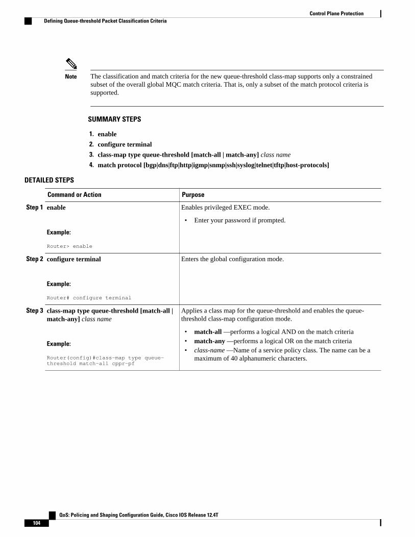
Note The classification and match criteria for the new queue-threshold class-map supports only a constrainedsubset of the overall global MQC match criteria. That is, only a subset of the match protocol criteria issupported.
SUMMARY STEPS
1. enable
2. configure terminal
3. class-map type queue-threshold [match-all | match-any] class name
4. match protocol [bgp|dns|ftp|http|igmp|snmp|ssh|syslog|telnet|tftp|host-protocols]
DETAILED STEPS
Command or Action Purpose
Step 1 enable
Example:
Router> enable
Enables privileged EXEC mode.
• Enter your password if prompted.
Step 2 configure terminal
Example:
Router# configure terminal
Enters the global configuration mode.
Step 3 class-map type queue-threshold [match-all |match-any] class name
Example:
Router(config)#class-map type queue-threshold match-all cppr-pf
Applies a class map for the queue-threshold and enables the queue-threshold class-map configuration mode.
• match-all —performs a logical AND on the match criteria• match-any —performs a logical OR on the match criteria• class-name —Name of a service policy class. The name can be a
maximum of 40 alphanumeric characters.
Control Plane Protection Defining Queue-threshold Packet Classification Criteria
QoS: Policing and Shaping Configuration Guide, Cisco IOS Release 12.4T104

Command or Action Purpose
Step 4 match protocol [bgp|dns|ftp|http|igmp|snmp|ssh|syslog|telnet|tftp|host-protocols]
Example:
Router(config-cmap)# match protocol bgp
Specifies the upper layer protocol match criteria for the class-map.
• bgp Border Gateway Protocol• dns —Domain Name Server lookup• ftp —File Transfer Protocol• http —World Wide Web traffic• igmp —Internet Group Management Protocol• snmp —Simple Network Management Protocol• ssh —Secure Shell Protocol• syslog —Syslog Server• telnet —Telnet• tftp —Trivial File Transfer Protocol• host-protocols —any open TCP/UDP port on the router.
Defining a Queue-threshold Service PolicyTo configure a queue-threshold service policy, use the new policy-map type called queue-threshold globalconfiguration command to specify the queue-threshold service policy name, and use the followingconfiguration commands to associate a queue-threshold traffic class that was configured with the class-maptype queue-threshold command, with the queue-threshold queue-limit action command. The queue-threshold traffic class is associated with the service policy when the class command is used. The classcommand must be issued after entering policy-map configuration mode. After entering the class command,you are automatically in policy-map class configuration mode.
Note The actions supported by the new queue-threshold service policy is limited. Only the queue-limit action issupported.
SUMMARY STEPS
1. enable
2. configure terminal
3. policy-map type queue-threshold policy-name
4. class class-name
5. queue-limit number
Control Plane ProtectionDefining a Queue-threshold Service Policy
QoS: Policing and Shaping Configuration Guide, Cisco IOS Release 12.4T 105

DETAILED STEPS
Command or Action Purpose
Step 1 enable
Example:
Router> enable
Enables privileged EXEC mode.
• Enter your password if prompted.
Step 2 configure terminal
Example:
Router# configure terminal
Enters the global configuration mode.
Step 3 policy-map type queue-threshold policy-name
Example:
Router(config)# policy-map type queue-threshold cppr-qt-policy
Enables the queue-threshold service policy configuration mode.
• policy-name —Name of a service policy map. The name can be amaximum of 40 alphanumeric characters.
Step 4 class class-name
Example:
Router(config-pcmap)# class qt-class
Enters class map configuration mode used to associate a servicepolicy with a class.
• class-name —Name of a service policy class. The name can be amaximum of 40 alphanumeric characters.
Step 5 queue-limit number
Example:
Router(config-cmap) #queue-limit 75
Applies the queue-threshold service policy action on the class.
Note Queue limit range is 0 to 255.
Applying a Queue-threshold Policy to the Host SubinterfacePerform this task to apply queue-threshold service policies to the control-plane host subinterface.
Before you attach a queue-threshold service policy to the control-plane host subinterface, you must firstcreate the policy by using MQC to define a class map and policy map for the required control-plane traffic.
Note The queue-threshold feature can only be applied on the control-plane host subinterface as an input policy.
Control Plane Protection Applying a Queue-threshold Policy to the Host Subinterface
QoS: Policing and Shaping Configuration Guide, Cisco IOS Release 12.4T106

SUMMARY STEPS
1. enable
2. configure terminal
3. control-plane [host | transit | cef-exception]
4. service-policy type queue-threshold {input} queue-threshold-policy-map-name
DETAILED STEPS
Command or Action Purpose
Step 1 enable
Example:
Router> enable
Enables privileged EXEC mode.
• Enter your password if prompted.
Step 2 configure terminal
Example:
Router# configure terminal
Enters the global configuration mode.
Step 3 control-plane [host | transit | cef-exception]
Example:
Router(config)# control-plane host
Attaches a QoS queue-threshold policy that manages traffic to the hostsubinterface and enters control-plane configuration mode.
• host —Enters the control-plane host subinterface configuration mode.
Note queue-threshold can only be applied to the host subinterface.
Step 4 service-policy type queue-threshold{input} queue-threshold-policy-map-name
Example:
Router(config-cp)# service-policy input cppr-qt-policy
Attaches a QoS service policy to the control-plane.
• input —Applies the specified service policy to packets received onthe control-plane.
• queue-threshold-policy-map-name —Name of a queue-thresholdservice policy map (created using the policy-map type queue-threshold command) to be attached. The name can be a maximum of40 alphanumeric characters.
• Examples, page 107
Examples
The following example shows how to configure a queue-threshold policy to set the queue limit for SNMPprotocol traffic to 50, telnet traffic to 50, and all other protocols to 150.
Router(config)# class-map type queue-threshold qt-snmp-classRouter(config-cmap)# match protocol snmpRouter(config-cmap)# class-map type queue-threshold qt-telnet-class Router(config-cmap)# match protocol telnetRouter(config-cmap)# class-map type queue-threshold qt-other-class Router(config-cmap)# match host-protocols
Control Plane ProtectionExamples
QoS: Policing and Shaping Configuration Guide, Cisco IOS Release 12.4T 107
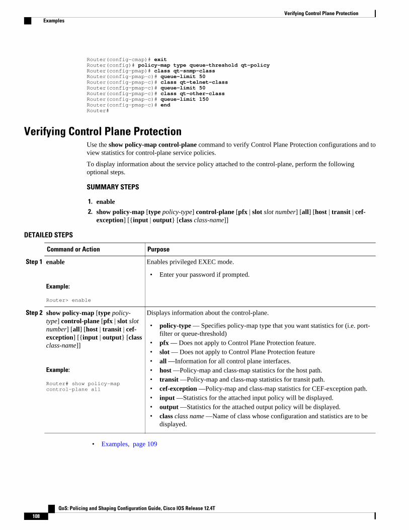
Router(config-cmap)# exitRouter(config)# policy-map type queue-threshold qt-policyRouter(config-pmap)# class qt-snmp-classRouter(config-pmap-c)# queue-limit 50Router(config-pmap-c)# class qt-telnet-classRouter(config-pmap-c)# queue-limit 50Router(config-pmap-c)# class qt-other-classRouter(config-pmap-c)# queue-limit 150Router(config-pmap-c)# endRouter#
Verifying Control Plane ProtectionUse the show policy-map control-plane command to verify Control Plane Protection configurations and toview statistics for control-plane service policies.
To display information about the service policy attached to the control-plane, perform the followingoptional steps.
SUMMARY STEPS
1. enable
2. show policy-map [type policy-type] control-plane [pfx | slot slot number] [all] [host | transit | cef-exception] [{input | output} [class class-name]]
DETAILED STEPS
Command or Action Purpose
Step 1 enable
Example:
Router> enable
Enables privileged EXEC mode.
• Enter your password if prompted.
Step 2 show policy-map [type policy-type] control-plane [pfx | slot slotnumber] [all] [host | transit | cef-exception] [{input | output} [classclass-name]]
Example:
Router# show policy-map control-plane all
Displays information about the control-plane.
• policy-type — Specifies policy-map type that you want statistics for (i.e. port-filter or queue-threshold)
• pfx — Does not apply to Control Plane Protection feature.• slot — Does not apply to Control Plane Protection feature• all —Information for all control plane interfaces.• host —Policy-map and class-map statistics for the host path.• transit —Policy-map and class-map statistics for transit path.• cef-exception —Policy-map and class-map statistics for CEF-exception path.• input —Statistics for the attached input policy will be displayed.• output —Statistics for the attached output policy will be displayed.• class class name —Name of class whose configuration and statistics are to be
displayed.
• Examples, page 109
Verifying Control Plane Protection Examples
QoS: Policing and Shaping Configuration Guide, Cisco IOS Release 12.4T108

ExamplesThe following example shows that the aggregate CoPP policy map named “copp-transit-policy” isassociated with the control-plane transit subinterface and displays the statistics for that policy:
Router# show policy-map control-plane transit control-plane Transit Service-policy input: copp-transit-policy Class-map: copp-transit-class (match-all) 8 packets, 592 bytes 5 minute offered rate 0 bps, drop rate 0 bps Match: any police: rate 2000 pps, burst 488 packets conformed 8 packets; actions: transmit exceeded 0 packets; actions: drop conformed 0 pps, exceed 0 pps Class-map: class-default (match-any) 0 packets, 0 bytes 5 minute offered rate 0 bps, drop rate 0 bps Match: any
The following example shows that the policy map “TEST” is associated with the aggregate control-planeinterface. This policy map polices traffic that matches the class map “TEST,” while allowing all othertraffic (that matches the class map “class-default”) to go through as is.
Router# show policy-map control-plane control-plane Service-policy input:TESTClass-map:TEST (match-all) 20 packets, 11280 bytes 5 minute offered rate 0 bps, drop rate 0 bps Match:access-group 101 police: 8000 bps, 1500 limit, 1500 extended limit conformed 15 packets, 6210 bytes; action:transmit exceeded 5 packets, 5070 bytes; action:drop violated 0 packets, 0 bytes; action:drop conformed 0 bps, exceed 0 bps, violate 0 bpsClass-map:class-default (match-any) 105325 packets, 11415151 bytes 5 minute offered rate 0 bps, drop rate 0 bps Match:any
Additional ReferencesRelated Documents
Related Topic Document Title
QoS commands: complete command syntax,command modes, command history, defaults, usageguidelines, and examples
Cisco IOS Quality of Service Solutions CommandReference
QoS feature overview “Quality of Service Overview” module
Control Plane ProtectionExamples
QoS: Policing and Shaping Configuration Guide, Cisco IOS Release 12.4T 109

Standards
Standard Title
No new or modified standards are supported by thisfeature, and support for existing standards has notbeen modified by this feature.
—
MIBs
MIB MIBs Link
• CISCO-CLASS-BASED-QOS-MIB
Note Supported only in Cisco IOS Release12.3(7)T.
To locate and download MIBs for selectedplatforms, Cisco IOS releases, and feature sets, useCisco MIB Locator, found at the following URL:
http://www.cisco.com/go/mibs
RFCs
RFC Title
None —
Technical Assistance
Description Link
The Cisco Technical Support website containsthousands of pages of searchable technical content,including links to products, technologies, solutions,technical tips, and tools. Registered Cisco.comusers can log in from this page to access even morecontent.
http://www.cisco.com/techsupport
Feature Information for Control Plane ProtectionThe following table provides release information about the feature or features described in this module.This table lists only the software release that introduced support for a given feature in a given softwarerelease train. Unless noted otherwise, subsequent releases of that software release train also support thatfeature.
Use Cisco Feature Navigator to find information about platform support and Cisco software image support.To access Cisco Feature Navigator, go to www.cisco.com/go/cfn. An account on Cisco.com is not required.
Control Plane Protection Feature Information for Control Plane Protection
QoS: Policing and Shaping Configuration Guide, Cisco IOS Release 12.4T110
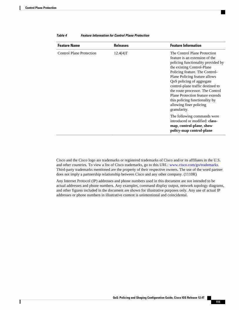
Table 4 Feature Information for Control Plane Protection
Feature Name Releases Feature Information
Control Plane Protection 12.4(4)T The Control Plane Protectionfeature is an extension of thepolicing functionality provided bythe existing Control-PlanePolicing feature. The Control-Plane Policing feature allowsQoS policing of aggregatecontrol-plane traffic destined tothe route processor. The ControlPlane Protection feature extendsthis policing functionality byallowing finer policinggranularity.
The following commands wereintroduced or modified: class-map, control-plane, showpolicy-map control-plane
Cisco and the Cisco logo are trademarks or registered trademarks of Cisco and/or its affiliates in the U.S.and other countries. To view a list of Cisco trademarks, go to this URL: www.cisco.com/go/trademarks.Third-party trademarks mentioned are the property of their respective owners. The use of the word partnerdoes not imply a partnership relationship between Cisco and any other company. (1110R)
Any Internet Protocol (IP) addresses and phone numbers used in this document are not intended to beactual addresses and phone numbers. Any examples, command display output, network topology diagrams,and other figures included in the document are shown for illustrative purposes only. Any use of actual IPaddresses or phone numbers in illustrative content is unintentional and coincidental.
Control Plane Protection
QoS: Policing and Shaping Configuration Guide, Cisco IOS Release 12.4T 111

Verifying Control Plane Protection
QoS: Policing and Shaping Configuration Guide, Cisco IOS Release 12.4T112

Control Plane Logging
The Cisco IOS Control Plane Protection features allow you to filter and rate-limit the packets that aregoing to the router’s control plane, and discard malicious and or error packets. The addition of the ControlPlane Logging feature enables logging of the packets that are dropped or permitted by these features. Youcan turn on logging for all or some packets that are processed by the control plane, without feature or classrestrictions, or you can enable logging for specific Control Plane Protection features such as control planepolicing, port-filtering, and queue-thresholding. The Control Plane Logging feature provides the loggingmechanism that is needed to efficiently deploy, monitor, and troubleshoot Control Plane Protectionfeatures.
• Finding Feature Information, page 113• Prerequisites for Control Plane Logging, page 113• Restrictions for Control Plane Logging, page 114• Information About Control Plane Logging, page 114• How to Configure Logging on a Control Plane Interface, page 116• Configuration Examples for Control Plane Logging, page 125• Additional References, page 128• Feature Information for Control Plane Logging, page 129
Finding Feature InformationYour software release may not support all the features documented in this module. For the latest featureinformation and caveats, see the release notes for your platform and software release. To find informationabout the features documented in this module, and to see a list of the releases in which each feature issupported, see the Feature Information Table at the end of this document.
Use Cisco Feature Navigator to find information about platform support and Cisco software image support.To access Cisco Feature Navigator, go to www.cisco.com/go/cfn. An account on Cisco.com is not required.
Prerequisites for Control Plane Logging• You understand the principles of control plane policing and how to classify control-plane traffic.• You understand the concepts and general configuration procedures for control plane protection,
including control plane policing, port-filtering, and queue-threshold.• You understand the concepts and general configuration procedure for applying QoS policies on a
router (class map and policy map).
For information about control plane policing and its capabilities, see the “Control Plane Policing” module.
QoS: Policing and Shaping Configuration Guide, Cisco IOS Release 12.4T 113

For information about control plane protection and its capabilities, see the “Control Plane Protection”module.
For information about Cisco IOS QoS and the procedure for configuring QoS in your network using theModular Quality of Service (QoS) Command-Line Interface (CLI) (MQC), see the QoS: Modular QoS:Command-Line Interface Configuration Guide.
Restrictions for Control Plane Logging• The Control Plane Logging feature logs control-plane packets only. This feature does not log data-
plane traffic that traverses the router on non-control-plane interfaces.• The Control Plane Logging feature logs IPv4 packets only. IPv6 packet logging is not supported.• Control plane logging is supported only on platforms that support control plane protection.• Packets permitted or dropped by the Management Plane Protection (MPP) feature can be logged only
via the Global Control Plane Logging mechanism. Feature-specific or class-specific control planelogging cannot be used to log MPP traffic.
• Global control plane logging can log only dropped or error packets on the aggregate control-planeinterface as a result of a control plane policing policy applied to the aggregate interface. To logallowed packets, you must apply the global control-plane logging policy to the host, transit, or cef-exception control-plane subinterface, or you must use feature-specific or class-specific logging.
• A packet that passes through the control plane can be logged only once using this feature. The stateprinted in the log message (PERMIT or DROP) is the final state of the packet on the control plane. Forexample, if there is a control-plane protection policy on the aggregate control-plane interface andanother on the host control-plane subinterface, with logging enabled on both, a packet that is allowedby both features will be logged only once (with a state of PERMIT). So a state of PERMIT whenlogged for a packet means that the packet was allowed by all control-plane protection features.
• Although logging control-plane traffic provides valuable insight into the details of control-planetraffic, logging excessive control-plane traffic might result in an overwhelming number of log entriesand possibly high router CPU usage. Use control plane logging for short periods of time and onlywhen needed to help classify, monitor, and troubleshoot control-plane traffic and features.
Information About Control Plane LoggingTo configure the Control Plane Logging feature, you should understand the following concepts:
• Global Control Plane Logging, page 114• Feature-Specific or Class-Specific Logging, page 115• Global Logging Configuration, page 115
Global Control Plane LoggingGlobal Control Plane Logging is a feature that allows logging of all or some packets processed by thecontrol plane, without feature or class restrictions. This can be used to log all, or a subset of, trafficpermitted or dropped by the Control Plane Protection Features. Packets to be logged can be filtered basedon the basis of multiple match criteria (for example, input interface, source IP address, or destination IPaddress).
Logging policies can also log packets on the basis of the action taken on them (that is, dropped orpermitted) by control plane features (that is, control plane policing, port-filtering or per-protocol queue-
Global Control Plane Logging Restrictions for Control Plane Logging
QoS: Policing and Shaping Configuration Guide, Cisco IOS Release 12.4T114
thresholding). Packets that are dropped by the control-plane infrastructure because of checksum errors canalso be filtered and logged. If you have not specified the kind of packet to be logged via the “permitted,”“dropped,” or “error” action match criteria, all packets (permitted, dropped, and error) will be consideredfor logging.
By default, the log messages contain source IP address, destination IP address, protocol name (IP/TCP/UDP), action (permit, drop, error), and port number. Additionally, there are options that can be configuredwith the log action that can enable logging of other fields in the IP header as well, such as TTL and packetlength. There is also an option to configure the rate-limit interval for which log messages are created; thatis, the interval between the logging of two messages.
The Global Control Plane Logging feature is configured using new MQC class-map, policy-map, andservice-policy types and can be applied on the aggregate control-plane interface or on a specific control-plane subinterface (that is, host, transit, or cef-exception).
Feature-Specific or Class-Specific LoggingFeature-specific or class-specific logging tracks only packets that match a specific class and that are actedupon by a specific control plane protection feature (that is, control plane policing, port-filtering, or per-protocol queue-thresholding). This type of logging differs from global logging, which allows you to log allpackets on a control-plane interface. With global logging, traffic that matches individual classes within acontrol plane protection feature policy cannot be distinguished. Global logging, for example, can log onlyall packets dropped on a control-plane interface as a whole. However, with feature-specific or class-specificlogging, packets that match a specific class and that are acted upon by a specific control plane protectionfeature will be separated out. Feature-specific or class-specific logging may be most valuable during theinitial stages of control plane protection deployment, when there is a need to know details about packetsthat match a specific class. For example, knowing what traffic is hitting your class-default class would helpin modifying your class maps or policy maps to account for stray packets or for determining characteristicsof an attack.
Feature-specific or class-specific logging provides feature-specific logging, making it possible to logpackets for a specific feature on a specific control-plane interface (for example, port-filtering on thecontrol-plane host interface).
Feature-specific or class-specific logging allows logging of packets that pass through a class map in acontrol plane protection feature service policy applied to a control-plane interface. When a feature, such ascontrol plane policing, is applied on a control-plane interface, feature-specific or class-specific logging canbe added as one of the actions to be performed on a class defined in the feature policy map. When loggingis added as an action for a class inside a policy map, all packets that match that class will be logged. Theonly packets filtered are those that the feature class map supports. There is no further classification done forlogging specifically. The log action keyword can be added by itself without any other policing actionsdefined in the class, or it can be added in addition to the police or drop action defined in the class. Whenthe log keyword is added as an action for a class inside a policy map, all packets (permitted and/ordropped) that match the class will be logged.
By default, the log messages contain source IP address, destination IP address, protocol name (IP/TCP/UDP), action (permit, drop, error), and port number. Additionally, there are options that can be configuredwith the log action that can enable logging of other fields in the IP header as well, such as TTL and packetlength. There is also an option to configure the rate-limit interval for which log messages are created; thatis, the interval between the logging of two messages.
Global Logging ConfigurationTo support global control plane logging, new MQC class-map, policy-map, and service-policy types werecreated. Policy-map type logging is used only for global control plane logging policies. Class-map type
Feature-Specific or Class-Specific LoggingInformation About Control Plane Logging
QoS: Policing and Shaping Configuration Guide, Cisco IOS Release 12.4T 115
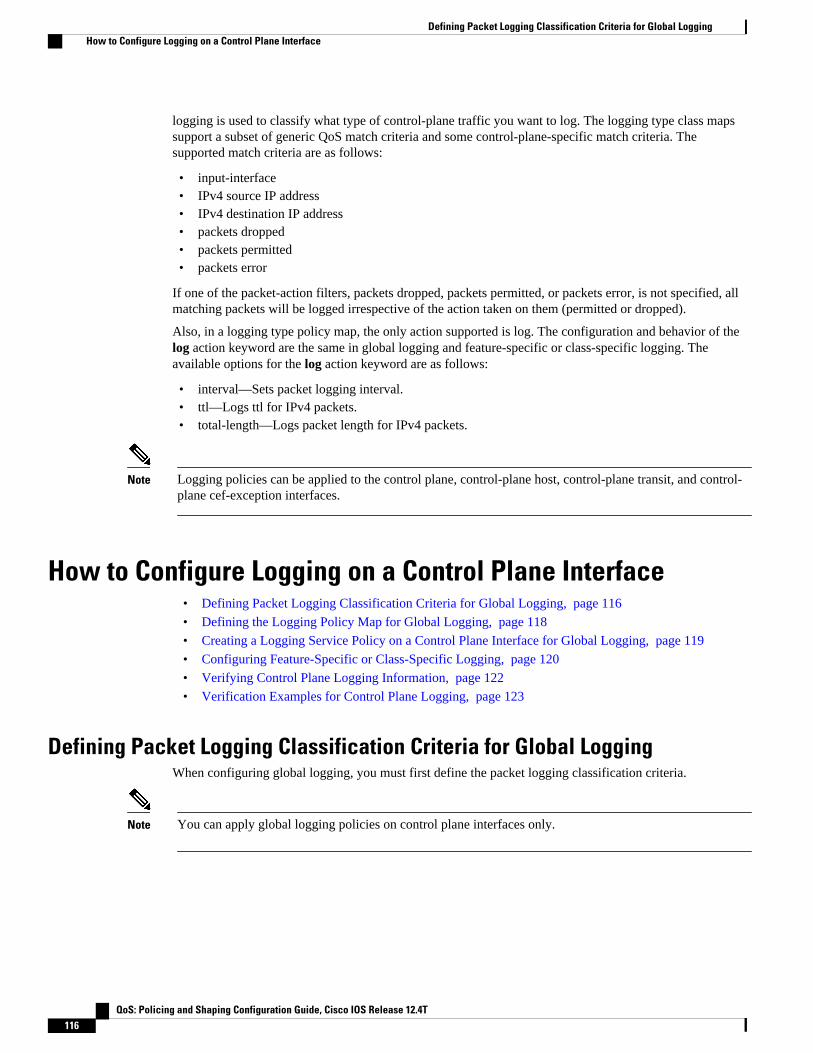
logging is used to classify what type of control-plane traffic you want to log. The logging type class mapssupport a subset of generic QoS match criteria and some control-plane-specific match criteria. Thesupported match criteria are as follows:
• input-interface• IPv4 source IP address• IPv4 destination IP address• packets dropped• packets permitted• packets error
If one of the packet-action filters, packets dropped, packets permitted, or packets error, is not specified, allmatching packets will be logged irrespective of the action taken on them (permitted or dropped).
Also, in a logging type policy map, the only action supported is log. The configuration and behavior of thelog action keyword are the same in global logging and feature-specific or class-specific logging. Theavailable options for the log action keyword are as follows:
• interval—Sets packet logging interval.• ttl—Logs ttl for IPv4 packets.• total-length—Logs packet length for IPv4 packets.
Note Logging policies can be applied to the control plane, control-plane host, control-plane transit, and control-plane cef-exception interfaces.
How to Configure Logging on a Control Plane Interface• Defining Packet Logging Classification Criteria for Global Logging, page 116
• Defining the Logging Policy Map for Global Logging, page 118
• Creating a Logging Service Policy on a Control Plane Interface for Global Logging, page 119
• Configuring Feature-Specific or Class-Specific Logging, page 120
• Verifying Control Plane Logging Information, page 122
• Verification Examples for Control Plane Logging, page 123
Defining Packet Logging Classification Criteria for Global LoggingWhen configuring global logging, you must first define the packet logging classification criteria.
Note You can apply global logging policies on control plane interfaces only.
Defining Packet Logging Classification Criteria for Global Logging How to Configure Logging on a Control Plane Interface
QoS: Policing and Shaping Configuration Guide, Cisco IOS Release 12.4T116

SUMMARY STEPS
1. enable
2. configure terminal
3. class-map [type {stack | access-control | port-filter | queue-threshold | logging}] [match-all |match-any] class-map-name
4. match [input-interface |ipv4source-address| ipv4destination-address | notinput-interface | packetspermitted | packets dropped | packets error]
5. end
DETAILED STEPS
Command or Action Purpose
Step 1 enable
Example:
Router> enable
Enables privileged EXEC mode.
• Enter your password if prompted.
Step 2 configure terminal
Example:
Router# configure terminal
Enters global configuration mode.
Step 3 class-map [type {stack | access-control | port-filter | queue-threshold | logging}] [match-all |match-any] class-map-name
Example:
Router(config)# class-map type logging match-all log-class
Creates a class map used to match packets to a specified class andenters class-map configuration mode. The following keywords andarguments can be used for control plane logging:
• type — (Optional) Identifies the class-map type. Use thelogging keywordfor control plane logging configurations.
• match-all — (Optional) Performs a logical AND on the matchcriteria.
• match-any — (Optional) Performs a logical OR on the matchcriteria.
• class-map name — Name of a class. The name can be amaximum of 40 alphanumeric characters.
Step 4 match [input-interface |ipv4source-address|ipv4destination-address | notinput-interface |packets permitted | packets dropped | packetserror]
Example:Router(config-cmap)# match packets dropped
Defines the match criteria for the logging class map.
Control Plane LoggingHow to Configure Logging on a Control Plane Interface
QoS: Policing and Shaping Configuration Guide, Cisco IOS Release 12.4T 117

Command or Action Purpose
Step 5 end
Example:
Router(config-cmap)# end
Exits class-map configuration mode and returns to privileged EXECmode.
Defining the Logging Policy Map for Global LoggingAfter you define packet logging criteria for global logging, you must define the logging policy map.
To configure global logging policy maps, use the new policy-map type logging configuration command.Then, use the class command, to associate a logging class-map that was configured with the class-maptype logging command, with the logging policy map. Use the log keyword to configure the log action forthe class that you associated with the policy map. The class command must be issued after entering thepolicy-map configuration mode. After entering the class command, you are automatically in policy-mapclass configuration mode. The action log can be configured while in policy-map class configuration mode.
Note You can apply global logging policies on control plane interfaces only.
SUMMARY STEPS
1. enable
2. configure terminal
3. policy-map [type {stack | access-control | port-filter | queue-threshold | logging}] policy-map-name
4. class class-name
5. log [interval seconds total-length ttl]
6. end
DETAILED STEPS
Command or Action Purpose
Step 1 enable
Example:
Router> enable
Enables privileged EXEC mode.
• Enter your password if prompted.
Step 2 configure terminal
Example:
Router# configure terminal
Enters global configuration mode.
Defining the Logging Policy Map for Global Logging How to Configure Logging on a Control Plane Interface
QoS: Policing and Shaping Configuration Guide, Cisco IOS Release 12.4T118

Command or Action Purpose
Step 3 policy-map [type {stack | access-control |port-filter | queue-threshold | logging}]policy-map-name
Example:
Router(config)# policy-map type logging log-policy
Creates the logging service policy and enters policy-map configurationmode.
• type — (Optional) Identifies the policy-map type. Use the loggingkeyword for control plane logging configurations.
• policy-map-name — Name of a policy map. The name can be amaximum of 40 alphanumeric characters.
Step 4 class class-name
Example:
Router(config-pmap)# class log-class
Associates a class with a policy map and enters class-map configurationmode.
• class-name — Name of a class of type logging. The name can be amaximum of 40 alphanumeric characters.
Step 5 log [interval seconds total-length ttl]
Example:
Router(config-pmap-c)# log interval 1000
Applies the log action to the logging class. With this command, you canenter the following optional parameters:
• interval seconds — (Optional) Sets packet logging interval.• total-length — (Optional) Logs packet length for IPv4 packets.• ttl — (Optional) Logs ttl for IPv4 packets.
Step 6 end
Example:
Router(config-pmap-c)# end
Exits from class-map configuration mode and returns to privileged EXECmode.
Creating a Logging Service Policy on a Control Plane Interface for GlobalLogging
After you define the logging service policy, you must apply the policy to a specific control plane interface.
Note You can apply global logging policies on control plane interfaces only.
SUMMARY STEPS
1. enable
2. configure terminal
3. control-plane [host | transit | cef-exception | cr]
4. service-policy type logging input logging-policy-map-name
5. end
Creating a Logging Service Policy on a Control Plane Interface for Global LoggingHow to Configure Logging on a Control Plane Interface
QoS: Policing and Shaping Configuration Guide, Cisco IOS Release 12.4T 119
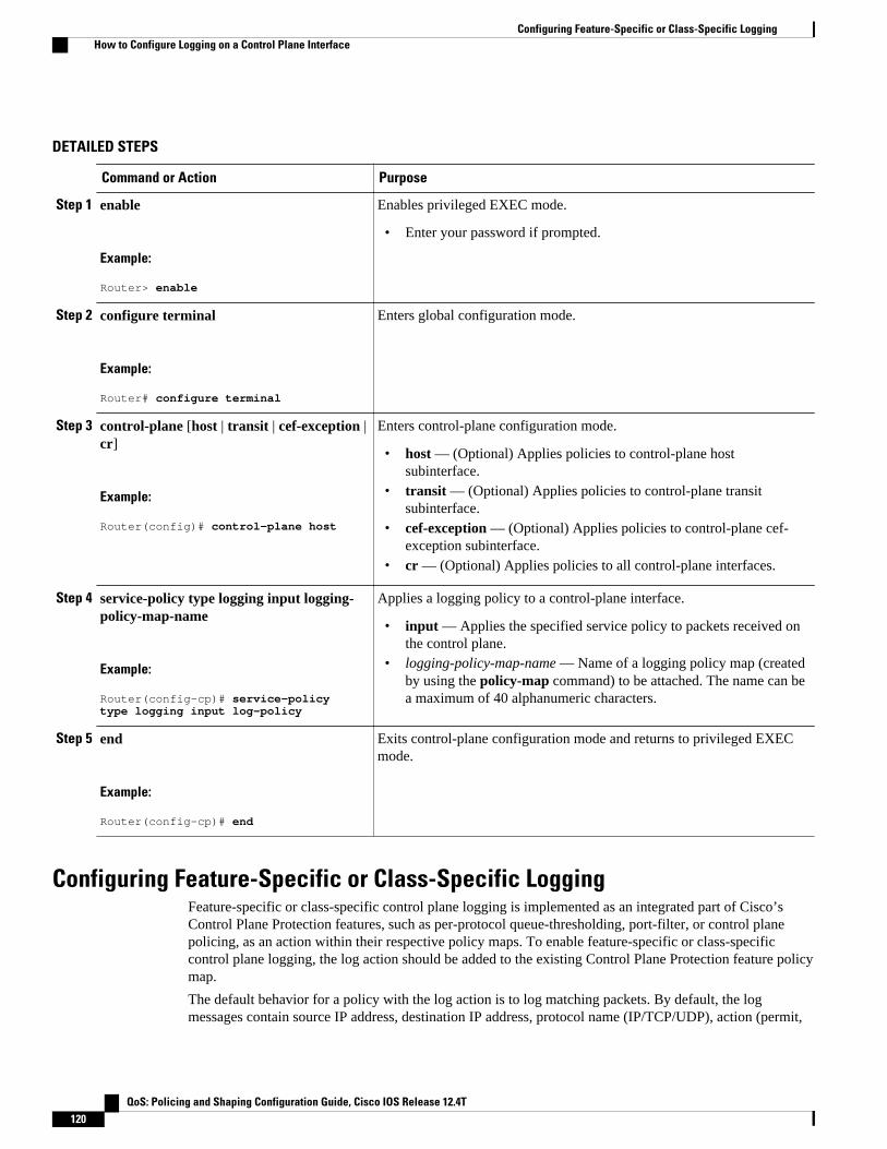
DETAILED STEPS
Command or Action Purpose
Step 1 enable
Example:
Router> enable
Enables privileged EXEC mode.
• Enter your password if prompted.
Step 2 configure terminal
Example:
Router# configure terminal
Enters global configuration mode.
Step 3 control-plane [host | transit | cef-exception |cr]
Example:
Router(config)# control-plane host
Enters control-plane configuration mode.
• host — (Optional) Applies policies to control-plane hostsubinterface.
• transit — (Optional) Applies policies to control-plane transitsubinterface.
• cef-exception — (Optional) Applies policies to control-plane cef-exception subinterface.
• cr — (Optional) Applies policies to all control-plane interfaces.
Step 4 service-policy type logging input logging-policy-map-name
Example:
Router(config-cp)# service-policy type logging input log-policy
Applies a logging policy to a control-plane interface.
• input — Applies the specified service policy to packets received onthe control plane.
• logging-policy-map-name — Name of a logging policy map (createdby using the policy-map command) to be attached. The name can bea maximum of 40 alphanumeric characters.
Step 5 end
Example:
Router(config-cp)# end
Exits control-plane configuration mode and returns to privileged EXECmode.
Configuring Feature-Specific or Class-Specific LoggingFeature-specific or class-specific control plane logging is implemented as an integrated part of Cisco’sControl Plane Protection features, such as per-protocol queue-thresholding, port-filter, or control planepolicing, as an action within their respective policy maps. To enable feature-specific or class-specificcontrol plane logging, the log action should be added to the existing Control Plane Protection feature policymap.
The default behavior for a policy with the log action is to log matching packets. By default, the logmessages contain source IP address, destination IP address, protocol name (IP/TCP/UDP), action (permit,
Configuring Feature-Specific or Class-Specific Logging How to Configure Logging on a Control Plane Interface
QoS: Policing and Shaping Configuration Guide, Cisco IOS Release 12.4T120
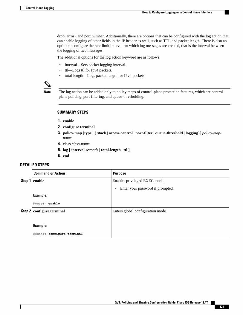
drop, error), and port number. Additionally, there are options that can be configured with the log action thatcan enable logging of other fields in the IP header as well, such as TTL and packet length. There is also anoption to configure the rate-limit interval for which log messages are created, that is the interval betweenthe logging of two messages.
The additional options for the log action keyword are as follows:
• interval—Sets packet logging interval.• ttl—Logs ttl for Ipv4 packets.• total-length—Logs packet length for IPv4 packets.
Note The log action can be added only to policy maps of control-plane protection features, which are controlplane policing, port-filtering, and queue-thresholding.
SUMMARY STEPS
1. enable
2. configure terminal
3. policy-map [type | { stack | access-control | port-filter | queue-threshold | logging}] policy-map-name
4. class class-name
5. log [ interval seconds | total-length | ttl ]
6. end
DETAILED STEPS
Command or Action Purpose
Step 1 enable
Example:
Router> enable
Enables privileged EXEC mode.
• Enter your password if prompted.
Step 2 configure terminal
Example:
Router# configure terminal
Enters global configuration mode.
Control Plane LoggingHow to Configure Logging on a Control Plane Interface
QoS: Policing and Shaping Configuration Guide, Cisco IOS Release 12.4T 121
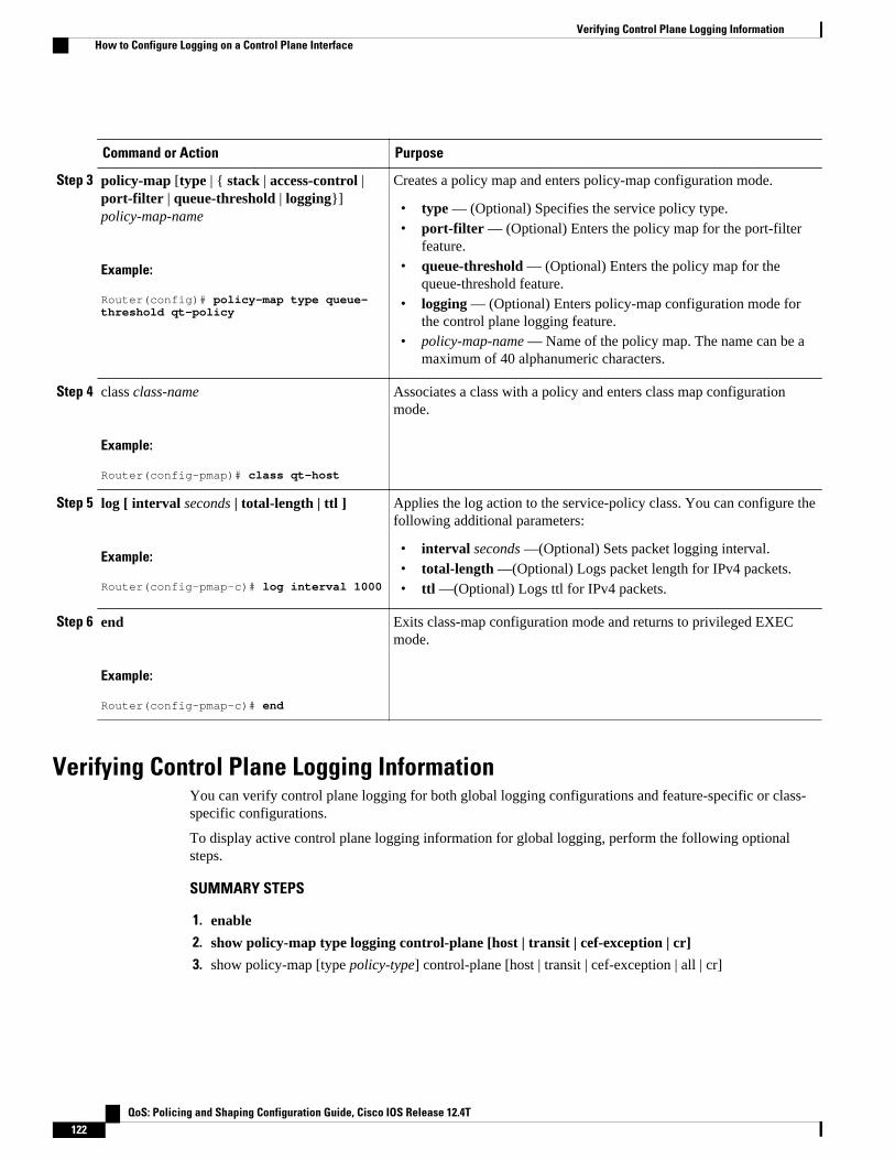
Command or Action Purpose
Step 3 policy-map [type | { stack | access-control |port-filter | queue-threshold | logging}]policy-map-name
Example:
Router(config)# policy-map type queue-threshold qt-policy
Creates a policy map and enters policy-map configuration mode.
• type — (Optional) Specifies the service policy type.• port-filter — (Optional) Enters the policy map for the port-filter
feature.• queue-threshold — (Optional) Enters the policy map for the
queue-threshold feature.• logging — (Optional) Enters policy-map configuration mode for
the control plane logging feature.• policy-map-name — Name of the policy map. The name can be a
maximum of 40 alphanumeric characters.
Step 4 class class-name
Example:
Router(config-pmap)# class qt-host
Associates a class with a policy and enters class map configurationmode.
Step 5 log [ interval seconds | total-length | ttl ]
Example:
Router(config-pmap-c)# log interval 1000
Applies the log action to the service-policy class. You can configure thefollowing additional parameters:
• interval seconds —(Optional) Sets packet logging interval.• total-length —(Optional) Logs packet length for IPv4 packets.• ttl —(Optional) Logs ttl for IPv4 packets.
Step 6 end
Example:
Router(config-pmap-c)# end
Exits class-map configuration mode and returns to privileged EXECmode.
Verifying Control Plane Logging InformationYou can verify control plane logging for both global logging configurations and feature-specific or class-specific configurations.
To display active control plane logging information for global logging, perform the following optionalsteps.
SUMMARY STEPS
1. enable
2. show policy-map type logging control-plane [host | transit | cef-exception | cr]
3. show policy-map [type policy-type] control-plane [host | transit | cef-exception | all | cr]
Verifying Control Plane Logging Information How to Configure Logging on a Control Plane Interface
QoS: Policing and Shaping Configuration Guide, Cisco IOS Release 12.4T122

DETAILED STEPS
Command or Action Purpose
Step 1 enable
Example:
Router> enable
Enables privileged EXEC mode.
• Enter your password if prompted.
Step 2 show policy-map type logging control-plane [host | transit |cef-exception | cr]
Example:
Router# show policy-map type
Display information for global control plane logging.
Step 3 show policy-map [type policy-type] control-plane [host | transit |cef-exception | all | cr]
Example:
Router# show policy-map type logging control-plane host
Display information for feature-specific or class-specific control plane logging.
Note The example shows feature-specific or class-specific logging enabled on a port-filter policy.
Verification Examples for Control Plane Logging• Sample Output for a Global Logging Configuration, page 123
• Sample Output for a Feature-Specific or Class-Specific Configuration, page 124
• Sample Log Output, page 124
Sample Output for a Global Logging ConfigurationThe following output displays the global logging service policy that was just added to the control-planehost feature path interface:
Router# show policy-map type logging control-plane host
Control Plane Host Service-policy logging input: cpplog-host-policy Class-map: cpplog-host-map (match-any) 0 packets, 0 bytes 5 minute offered rate 0 bps, drop rate 0 bps Match: packets dropped 0 packets, 0 bytes 5 minute rate 0 bps Match: packets permitted 0 packets, 0 bytes 5 minute rate 0 bps Class-map: class-default (match-any) 0 packets, 0 bytes 5 minute offered rate 0 bps, drop rate 0 bps Match: any
Verification Examples for Control Plane LoggingSample Output for a Global Logging Configuration
QoS: Policing and Shaping Configuration Guide, Cisco IOS Release 12.4T 123

Sample Output for a Feature-Specific or Class-Specific ConfigurationThe following output displays the logging policy map that was just added to the control-plane host featurepath interface:
Router# show policy-map cpp-policy
Policy Map cpp-policy Class cppclass-igp Class cppclass-management police rate 250 pps burst 61 packets conform-action transmit exceed-action drop Class cppclass-monitoring police rate 100 pps burst 24 packets conform-action transmit exceed-action drop Class cppclass-undesirable drop log interval 5000 Class class-default police rate 50 pps burst 12 packets conform-action transmit exceed-action drop
Sample Log OutputThe following example shows log output for a configuration that sends IP traffic to the router:
Router#%CP-6-IP: PERMIT ttl=59 length=20 209.165.200.225 -> 209.165.200.254 %CP-6-IP: PERMIT ttl=59 length=20 209.165.200.225 -> 209.165.200.254 %CP-6-IP: PERMIT ttl=59 length=20 209.165.200.225 -> 209.165.200.254 %CP-6-IP: PERMIT ttl=59 length=20 209.165.200.225 -> 209.165.200.254
The following is a description of the log information displayed in the preceeding example:
• IP denotes the kind of traffic received.• PERMIT means that no control-plane feature dropped the packet.• ttl gives the ttl value in the IP header.• length gives the total-length field in the IP header.• 209.165.200.225 is the source IP address.• 209.165.200.254 is the destination IP address.
The following example shows log output for a configuration that sends TCP traffic to the router:
Router#
%CP-6-TCP: PERMIT ttl=59 length=40 209.165.200.225(18611) -> 209.165.200.254(23)%CP-6-TCP: PERMIT ttl=59 length=40 209.165.200.225(18611) -> 209.165.200.254(23)%CP-6-TCP: PERMIT ttl=59 length=40 209.165.200.225(18611) -> 209.165.200.254(23)%CP-6-TCP: PERMIT ttl=59 length=40 209.165.200.225(18611) -> 209.165.200.254(23)
The following is a description of the log information displayed in the preceding example:
• TCP denotes the kind of traffic received.• PERMIT means that no control-plane feature dropped the packet.• ttl gives the ttl value in the IP header.• length gives the total-length field in the IP header.• 209.165.200.225 is the source IP address.• 18611 is the source TCP port.
Control Plane Logging Sample Output for a Feature-Specific or Class-Specific Configuration
QoS: Policing and Shaping Configuration Guide, Cisco IOS Release 12.4T124

• 209.165.200.254 is the destination IP address.• 23 is the destination TCP port.
Configuration Examples for Control Plane LoggingThis section provides the following configuration examples:
• Configuring Global Control Plane Logging for Dropped and Permitted Packets Example, page 125• Configuring Global Control Plane Logging for Dropped Packets Example, page 126• Configuring Logging for a Specific Class Example, page 126• Configuring Logging for a Port-Filter Policy Map Example, page 127
Configuring Global Control Plane Logging for Dropped and PermittedPackets Example
The following example shows how to configure a global control-plane logging service policy to log alldropped and permitted packets that hit the control-plane host feature path only, regardless of the interfacefrom which the packets enter the router. Also, the router rate-limits the log messages to one every 5seconds.
! Define a class map of type logging to specify what packets will be logged.Router# configure terminal
Enter configuration commands, one per line. End with CNTL/Z.Router(config)# class-map type logging match-any cpplog-host-mapRouter(config-cmap)# match packets droppedRouter(config-cmap)# match packets permittedRouter(config-cmap)# exit
! Define a policy map of type logging using your logging class map and rate-limit log messages to one every 5 seconds.Router(config)# policy-map type logging cpplog-host-policyRouter(config-pmap)# class cpplog-host-mapRouter(config-pmap-c)# log interval 5000Router(config-pmap-c)# exitRouter(config-pmap)# exit
! Apply the new logging policy map to the control-plane host feature path interface.Router(config)# control-plane hostRouter(config-cp)# service-policy type logging input cpplog-host-policyRouter(config-cp)# endRouter#Aug 8 17:57:57.359: %SYS-5-CONFIG_I: Configured from console by cisco on consoleRouter#
The following output displays the logging policy map that was just added to the control-plane host featurepath interface:
Router# show policy-map type logging control-plane host
Control Plane Host Service-policy logging input: cpplog-host-policy Class-map: cpplog-host-map (match-any) 0 packets, 0 bytes 5 minute offered rate 0 bps, drop rate 0 bps Match: packets dropped 0 packets, 0 bytes 5 minute rate 0 bps Match: packets permitted 0 packets, 0 bytes
Configuring Global Control Plane Logging for Dropped and Permitted Packets ExampleConfiguration Examples for Control Plane Logging
QoS: Policing and Shaping Configuration Guide, Cisco IOS Release 12.4T 125

5 minute rate 0 bps log interval 5000 Class-map: class-default (match-any) 0 packets, 0 bytes 5 minute offered rate 0 bps, drop rate 0 bps Match: any
Configuring Global Control Plane Logging for Dropped Packets ExampleThe following example shows how to configure a global control-plane logging service policy to log alldropped packets that come from GigabitEthernet interface 0/3 that hit the aggregate control-plane interface.
! Define a class map of type logging to specify what packets will be logged.Router# configure terminal
Enter configuration commands, one per line. End with CNTL/Z.Router(config)# class-map type logging match-all cpplog-gigRouter(config-cmap)# match input-interface gigabitethernet 0/3Router(config-cmap)# match packets droppedRouter(config-cmap)# exit
! Define a policy map of type logging using your logging type class map.Router(config)# policy-map type logging cpplog-gig-policy
Router(config-pmap)# class cpplog-gigRouter(config-pmap-c)# logRouter(config-pmap-c)# exitRouter(config-pmap)# exit
! Apply the new logging policy map to the aggregate control-plane interface.Router(config)# control-planeRouter(config-cp)# service-policy type logging input cpplog-gig-policyRouter(config-cp)# endRouter#Aug 8 12:53:08.618: %SYS-5-CONFIG_I: Configured from console by cisco on consoleRouter#
The following output displays the logging policy map that was just added to the aggregate control-planeinterface:
Router# show policy-map type logging control-plane
Control Plane Service-policy logging input: cpplog-gig-policy Class-map: cpplog-gig (match-all) 0 packets, 0 bytes 5 minute offered rate 0 bps, drop rate 0 bps Match: input-interface GigabitEthernet0/3 Match: dropped-packets log Class-map: class-default (match-any) 0 packets, 0 bytes 5 minute offered rate 0 bps, drop rate 0 bps Match: any
Configuring Logging for a Specific Class ExampleThe following example shows how to configure class-specific control plane logging for a specific classconfigured in a control plane policing service policy. This example also shows how to configure rate-limiting of logs to output only one log message every 5 seconds. For this example, you have a control planepolicing service policy with classes defined for Interior Gateway Protocol (IGP), management, monitoringand, undesirable traffic. The undesirable class is configured to match packets that are destined to the routeron UDP port 1434. The service policy is configured to drop all packets that hit the undesirable class (in thiscase, packets that are destined for port 1434). For this example, you want to log all packets being droppedby the undesirable class, so that you will be aware that you are being attacked by 1434 packets.
Configuring Global Control Plane Logging for Dropped Packets Example Configuration Examples for Control Plane Logging
QoS: Policing and Shaping Configuration Guide, Cisco IOS Release 12.4T126

In this example, you have the following control plane policing service policy configured:
Router# show policy-map cpp-policy
Policy Map cpp-policy Class cppclass-igp Class cppclass-management police rate 250 pps burst 61 packets conform-action transmit exceed-action drop Class cppclass-monitoring police rate 100 pps burst 24 packets conform-action transmit exceed-action drop Class cppclass-undesirable drop Class class-default police rate 50 pps burst 12 packets conform-action transmit exceed-action drop
To log all traffic for the undesirable class in the above service policy, perform the following steps:
! Enter control plane policing policy-map configuration mode.Router# configure terminal
Enter configuration commands, one per line. End with CNTL/Z.Router(config)# policy-map cpp-policy
! Enter policy-map class configuration mode for the undesirable class.Router(config-pmap)# class cppclass-undesirable
! Configure the log keyword with a rate limit of one log message every 5 seconds.Router(config-pmap-c)# log interval 5000Router(config-pmap-c)# end
Use the following command to verify that the log action has been added to the policy map under theundesirable class:
Router# show policy-map cpp-policy
Policy Map cpp-policy Class cppclass-igp Class cppclass-management police rate 250 pps burst 61 packets conform-action transmit exceed-action drop Class cppclass-monitoring police rate 100 pps burst 24 packets conform-action transmit exceed-action drop Class cppclass-undesirable droplog interval 5000 Class class-default police rate 50 pps burst 12 packets conform-action transmit exceed-action drop
Configuring Logging for a Port-Filter Policy Map ExampleThe following example shows how to configure class-specific control plane logging for a specific classconfigured in a Control Plane Protection port-filter policy map. This example also shows how to configurelogging to display the packet-length field from the IP header for each packet that hits the port-filter class.For this example, you have a port-filter policy map configured to drop all traffic that is destined to closedTCP/UDP ports. For this example, you want to log all packets that are being dropped or allowed by theport-filter class.
Configuring Logging for a Port-Filter Policy Map ExampleConfiguration Examples for Control Plane Logging
QoS: Policing and Shaping Configuration Guide, Cisco IOS Release 12.4T 127
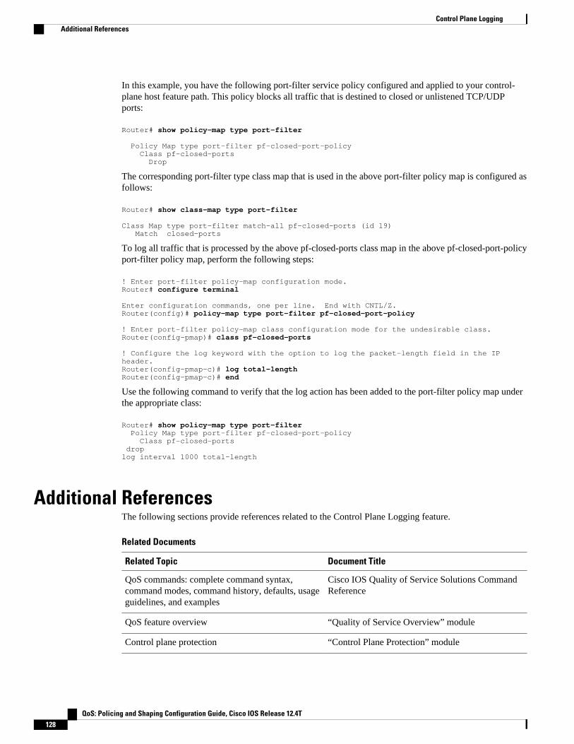
In this example, you have the following port-filter service policy configured and applied to your control-plane host feature path. This policy blocks all traffic that is destined to closed or unlistened TCP/UDPports:
Router# show policy-map type port-filter
Policy Map type port-filter pf-closed-port-policy Class pf-closed-ports Drop
The corresponding port-filter type class map that is used in the above port-filter policy map is configured asfollows:
Router# show class-map type port-filter Class Map type port-filter match-all pf-closed-ports (id 19) Match closed-ports
To log all traffic that is processed by the above pf-closed-ports class map in the above pf-closed-port-policyport-filter policy map, perform the following steps:
! Enter port-filter policy-map configuration mode.Router# configure terminal
Enter configuration commands, one per line. End with CNTL/Z.Router(config)# policy-map type port-filter pf-closed-port-policy
! Enter port-filter policy-map class configuration mode for the undesirable class.Router(config-pmap)# class pf-closed-ports
! Configure the log keyword with the option to log the packet-length field in the IP header. Router(config-pmap-c)# log total-length Router(config-pmap-c)# end
Use the following command to verify that the log action has been added to the port-filter policy map underthe appropriate class:
Router# show policy-map type port-filter Policy Map type port-filter pf-closed-port-policy Class pf-closed-ports droplog interval 1000 total-length
Additional ReferencesThe following sections provide references related to the Control Plane Logging feature.
Related Documents
Related Topic Document Title
QoS commands: complete command syntax,command modes, command history, defaults, usageguidelines, and examples
Cisco IOS Quality of Service Solutions CommandReference
QoS feature overview “Quality of Service Overview” module
Control plane protection “Control Plane Protection” module
Control Plane Logging Additional References
QoS: Policing and Shaping Configuration Guide, Cisco IOS Release 12.4T128

Standards
Standard Title
No new or modified standards are supported by thisfeature, and support for existing standards has notbeen modified by this feature.
—
MIBs
MIB MIBs Link
None To locate and download MIBs for selectedplatforms, Cisco IOS releases, and feature sets, useCisco MIB Locator found at the following URL:
http://www.cisco.com/go/mibs
RFCs
RFC Title
None —
Technical Assistance
Description Link
The Cisco Technical Support website containsthousands of pages of searchable technical content,including links to products, technologies, solutions,technical tips, and tools. Registered Cisco.comusers can log in from this page to access even morecontent.
http://www.cisco.com/techsupport
Feature Information for Control Plane LoggingThe following table provides release information about the feature or features described in this module.This table lists only the software release that introduced support for a given feature in a given softwarerelease train. Unless noted otherwise, subsequent releases of that software release train also support thatfeature.
Use Cisco Feature Navigator to find information about platform support and Cisco software image support.To access Cisco Feature Navigator, go to www.cisco.com/go/cfn. An account on Cisco.com is not required.
Control Plane LoggingFeature Information for Control Plane Logging
QoS: Policing and Shaping Configuration Guide, Cisco IOS Release 12.4T 129

Table 5 Feature Information for Control Plane Logging
Feature Name Releases Feature Information
Control Plane Logging 12.4(6)T Allows the control plane featuresto log all packets that match theclass-map entries.
The following commands wereintroduced or modified: class-map, debug control-plane ,policy-map
Cisco and the Cisco logo are trademarks or registered trademarks of Cisco and/or its affiliates in the U.S.and other countries. To view a list of Cisco trademarks, go to this URL: www.cisco.com/go/trademarks.Third-party trademarks mentioned are the property of their respective owners. The use of the word partnerdoes not imply a partnership relationship between Cisco and any other company. (1110R)
Any Internet Protocol (IP) addresses and phone numbers used in this document are not intended to beactual addresses and phone numbers. Any examples, command display output, network topology diagrams,and other figures included in the document are shown for illustrative purposes only. Any use of actual IPaddresses or phone numbers in illustrative content is unintentional and coincidental.
Control Plane Logging
QoS: Policing and Shaping Configuration Guide, Cisco IOS Release 12.4T130

Class-Based Policing
Feature History
Release Modification
12.1(5)T This command was introduced for Cisco IOSRelease 12.1 T. A new Class-Based Policingalgorithm was introduced. The violate-actionoption became available. This feature becameavailable on Cisco 2600, 3600, 4500, 7200, and7500 series routers.
12.2(2)T The set-clp-transmit option for the actionargument was added to the police command. Theset-frde-transmit option for the action argumentwas added to the police command. The set-mpls-exp-transmit option for the action argument wasadded to the police command.
12.0(26)S This feature was integrated into Cisco IOSRelease 12.0(26)S for the Cisco 7200 and 7500series routers. The name of the feature changedfrom Traffic Policing to Class-Based Policing.
• Finding Feature Information, page 131• Feature Overview, page 132• Prerequisites, page 133• Configuration Tasks, page 133• Monitoring and Maintaining Traffic Policing, page 134• Configuration Examples, page 135• Additional References, page 136
Finding Feature InformationYour software release may not support all the features documented in this module. For the latest featureinformation and caveats, see the release notes for your platform and software release. To find informationabout the features documented in this module, and to see a list of the releases in which each feature issupported, see the Feature Information Table at the end of this document.
Use Cisco Feature Navigator to find information about platform support and Cisco software image support.To access Cisco Feature Navigator, go to www.cisco.com/go/cfn. An account on Cisco.com is not required.
QoS: Policing and Shaping Configuration Guide, Cisco IOS Release 12.4T 131

Feature OverviewThis feature module describes the Class-Based Policing feature. The Class-Based Policing feature performsthe following functions:
• Limits the input or output transmission rate of a class of traffic based on user-defined criteria• Marks packets by setting the ATM Cell Loss Priority (CLP) bit, Frame Relay Discard Eligibility (DE)
bit, IP precedence value, IP differentiated services code point (DSCP) value, MPLS experimentalvalue, and Quality of Service (QoS) group.
Class-Based Policing allows you to control the maximum rate of traffic transmitted or received on aninterface. The Class-Based Policing feature is applied when you attach a traffic policy contain the Class-Based Policing configuration to an interface. A traffic policy.
• Benefits, page 132
• Restrictions, page 133
Benefits
Bandwidth Management Through Rate Limiting
Class-Based Policing allows you to control the maximum rate of traffic transmitted or received on aninterface. Class-Based Policing is often configured on interfaces at the edge of a network to limit trafficinto or out of the network. In most Class-Based Policing configurations, traffic that falls within the rateparameters is transmitted, whereas traffic that exceeds the parameters is dropped or transmitted with adifferent priority.
Packet Marking
Packet marking allows you to partition your network into multiple priority levels or classes of service(CoS). A packet is marked and these markings can be used to identify and classify traffic for downstreamdevices. In some cases, such as ATM Cell Loss Priority (CLP) marking or Frame Relay Discard Eligibility(DE) marking, the marking is used to classify traffic.
• Use Class-Based Policing to set the IP precedence or DSCP values for packets entering the network.Networking devices within your network can then use the adjusted IP precedence values to determinehow the traffic should be treated. For example, the Weighted Random Early Detection (WRED)feature uses the IP precedence values to determine the probability that a packet will be dropped.
• Use Class-Based Policing to assign packets to a QoS group. The router uses the QoS group todetermine how to prioritize packets within the router.
Traffic can be marked without using the Class-Based Policing feature. If you want to mark traffic but donot want to use Class-Based Policing, see the "Marking Network Traffic" module.
Packet Prioritization for Frame Relay Frames
The Class-Based Policing feature allows users to mark the Frame Relay DE bit of the Frame Relay frame.The Frame Relay DE bit is one bit and, therefore, can be set to either 0 or 1. In congested environments,frames with the DE bit set to 1 are discarded before frames with the DE bit set to 0.
Benefits Feature Overview
QoS: Policing and Shaping Configuration Guide, Cisco IOS Release 12.4T132
Packet Prioritization for ATM Cells
The Class-Based Policing feature allows users to mark the ATM CLP bit in ATM cells. The ATM CLP bitis used to prioritize packets in ATM networks. The ATM CLP bit is one bit and, therefore, can be set toeither 0 or 1. In congested environments, cells with the ATM CLP bit set to 1 are discarded before cellswith the ATM CLP bit set to 0.
Restrictions• To use the set-clp-transmitaction available with this feature, the Enhanced ATM Port Adapter (PA-
A3) is required. Therefore, the set-clp-transmit action is not supported on any platform that does notsupport the PA-A3 adapter (such as the Cisco 2600 series router, the Cisco 3640 router, and the 4500series router). For more information, see the documentation for your specific router.
• On a Cisco 7500 series router, Class-Based Policing can monitor Cisco Express Forwarding (CEF)switching paths only. In order to use the Class-Based Policing feature, Cisco Express Forwarding mustbe configured on both the interface receiving the packet and the interface sending the packet.
• On a Cisco 7500 series router, Class-Based Policing cannot be applied to packets that originated fromor are destined to a router.
• Class-Based Policing can be configured on an interface or a subinterface.• Class-Based Policing is not supported on the following interfaces:
◦ Fast EtherChannel◦ Tunnel
Note Class-Based Policing is supported on tunnels that are using the Cisco generic routing encapsulation (GRE)tunneling protocol.
• ◦ PRI◦ Any interface on a Cisco 7500 series router that does not support Cisco Express Forwarding
PrerequisitesOn a Cisco 7500 series router, Cisco Express Forwarding (CEF) must be configured on the interface beforeClass-Based Policing can be used.
Configuration Tasks• Configuring Traffic Policing, page 134
• Verifying Traffic Policing, page 134
• Troubleshooting Tips, page 134
RestrictionsPrerequisites
QoS: Policing and Shaping Configuration Guide, Cisco IOS Release 12.4T 133

Configuring Traffic PolicingCommand Purpose
Router(config-pmap-c)# police bps burst-normalburst-max conform-action action exceed-actionaction violate-action action
Specifies a maximum bandwidth usage by a trafficclass.
Note The Class-Based Policing feature workswith a token bucket mechanism. There arecurrently two types of token bucketalgorithms: a single token bucket algorithmand a two token bucket algorithm. A singletoken bucket system is used when theviolate-action option is not specified, and atwo token bucket system is used when theviolate-action option is specified.
Verifying Traffic PolicingUse the show policy-map interface EXEC command to verify that the Class-Based Policing feature isconfigured on your interface. If the feature is configured on your interface, the show policy-map interfacecommand output displays policing statistics:
Router# show policy-map interface Ethernet1/7 service-policy output: x class-map: a (match-all) 0 packets, 0 bytes 5 minute rate 0 bps match: ip precedence 0 police: 1000000 bps, 10000 limit, 10000 extended limit conformed 0 packets, 0 bytes; action: transmit exceeded 0 packets, 0 bytes; action: drop conformed 0 bps, exceed 0 bps, violate 0 bps
Troubleshooting Tips• Check the interface type. Verify that your interface is not mentioned in the nonsupported interface
description in the Restrictions, page 133 section of this module.• For input Class-Based Policing on a Cisco 7500 series router, verify that CEF is configured on the
interface where Class-Based Policing is configured.• For output Class-Based Policing on a Cisco 7500 series router, ensure that the incoming traffic is CEF-
switched. Class-Based Policing cannot be used on the switching path unless CEF switching is enabled.
Monitoring and Maintaining Traffic PolicingCommand Purpose
Router# show policy-map Displays all configured policy maps.
Configuring Traffic Policing Monitoring and Maintaining Traffic Policing
QoS: Policing and Shaping Configuration Guide, Cisco IOS Release 12.4T134

Command Purpose
Router# show policy-map policy-map-name Displays the user-specified policy map.
Router# show policy-map interface Displays statistics and configurations of all inputand output policies that are attached to an interface.
Router# show policy-map interface serviceinstance
Displays the policy map information for a givenservice instance under a port channel.
Configuration Examples• Example Configuring a Service Policy that Includes Traffic Policing, page 135
Example Configuring a Service Policy that Includes Traffic PolicingIn the following example, Class-Based Policing is configured with the average rate at 8000 bits per second,the normal burst size at 1000 bytes, and the excess burst size at 1000 bytes for all packets leaving FastEthernet interface 0/0.
class-map access-matchmatch access-group 1exitpolicy-map police-settingclass access-matchpolice 8000 1000 1000 conform-action transmit exceed-action set-qos-transmit 1 violate-action dropexitexitservice-policy output police-setting
The treatment of a series of packets leaving Fast Ethernet interface 0/0 depends on the size of the packetand the number of bytes remaining in the conform and exceed token buckets. The series of packets arepoliced based on the following rules:
• If the previous arrival of the packet was at T1 and the current arrival of the packet is at T, the bucket isupdated with T -T1 worth of bits based on the token arrival rate. The refill tokens are placed in theconform bucket. If the tokens overflow the conform bucket, the overflow tokens are placed in theexceed bucket. The token arrival rate is calculated as follows:
(time between packets <which is equal to T - T1> * policer rate)/8 bytes
• If the number of bytes in the conform bucket B is greater than or equal to 0, the packet conforms andthe conform action is taken on the packet. If the packet conforms, B bytes are removed from theconform bucket and the conform action is taken. The exceed bucket is unaffected in this scenario.
• If the number of bytes in the conform bucket B is less than 0, the excess token bucket is checked forbytes by the packet. If the number of bytes in the exceed bucket B is greater than or equal to 0, theexceed action is taken and B bytes are removed from the exceed token bucket. No bytes are removedfrom the conform bucket in this scenario.
• If the number bytes in the exceed bucket B is fewer than 0, the packet violates the rate and the violateaction is taken. The action is complete for the packet.
Example Configuring a Service Policy that Includes Traffic PolicingConfiguration Examples
QoS: Policing and Shaping Configuration Guide, Cisco IOS Release 12.4T 135

In this example, the initial token buckets starts full at 1000 bytes. If a 450-byte packet arrives, the packetconforms because enough bytes are available in the conform token bucket. The conform action (send) istaken by the packet and 450 bytes are removed from the conform token bucket (leaving 550 bytes).
If the next packet arrives 0.25 seconds later, 250 bytes are added to the conform token bucket
((0.25 * 8000)/8), leaving 800 bytes in the conform token bucket. If the next packet is 900 bytes, the packetdoes not conform because only 800 bytes are available in the conform token bucket.
The exceed token bucket, which starts full at 1000 bytes (as specified by the excess burst size) is thenchecked for available bytes. Because enough bytes are available in the exceed token bucket, the exceedaction (set the QoS transmit value of 1) is taken and 900 bytes are taken from the exceed bucket (leaving100 bytes in the exceed token bucket.
If the next packet arrives 0.40 seconds later, 400 bytes are added to the token buckets ((.40 * 8000)/8).Therefore, the conform token bucket now has 1000 bytes (the maximum number of tokens available in theconform bucket) and 200 bytes overflow the conform token bucket (because it only 200 bytes were neededto fill the conform token bucket to capacity). These overflow bytes are placed in the exceed token bucket,giving the exceed token bucket 300 bytes.
If the arriving packet is 1000 bytes, the packet conforms because enough bytes are available in the conformtoken bucket. The conform action (transmit) is taken by the packet, and 1000 bytes are removed from theconform token bucket (leaving 0 bytes).
If the next packet arrives 0.20 seconds later, 200 bytes are added to the token bucket ((.20 * 8000)/8).Therefore, the conform bucket now has 200 bytes. If the arriving packet is 400 bytes, the packet does notconform because only 200 bytes are available in the conform bucket. Similarly, the packet does not exceedbecause only 300 bytes are available in the exceed bucket. Therefore, the packet violates and the violateaction (drop) is taken.
Additional ReferencesThe following sections provide references related to Traffic Policing.
Related Documents
Related Topic Document Title
Traffic policing "Traffic Policing" module
Modular Quality of Service Command-LineInterface (MQC)
"Applying QoS Features Using the MQC" module
Standards
Standards Title
No new or modified standards are supported by thisfeature, and support for existing standards has notbeen modified by this feature.
--
Class-Based Policing Additional References
QoS: Policing and Shaping Configuration Guide, Cisco IOS Release 12.4T136

MIBs
MIBs MIBs Link
Class-Based Quality of Service MIB
• CISCO-CLASS-BASED-QOS-MIB• CISCO-CLASS-BASED-QOS-CAPABILITY-
MIB
To locate and download MIBs for selectedplatforms, Cisco IOS releases, and feature sets, useCisco MIB Locator found at the following URL:
http://www.cisco.com/go/mibs
RFCs
RFCs Title
RFC 2697 A Single Rate Three Color Marker
Technical Assistance
Description Link
The Cisco Support and Documentation websiteprovides online resources to downloaddocumentation, software, and tools. Use theseresources to install and configure the software andto troubleshoot and resolve technical issues withCisco products and technologies. Access to mosttools on the Cisco Support and Documentationwebsite requires a Cisco.com user ID andpassword.
http://www.cisco.com/cisco/web/support/index.html
Cisco and the Cisco logo are trademarks or registered trademarks of Cisco and/or its affiliates in the U.S.and other countries. To view a list of Cisco trademarks, go to this URL: www.cisco.com/go/trademarks.Third-party trademarks mentioned are the property of their respective owners. The use of the word partnerdoes not imply a partnership relationship between Cisco and any other company. (1110R)
Any Internet Protocol (IP) addresses and phone numbers used in this document are not intended to beactual addresses and phone numbers. Any examples, command display output, network topology diagrams,and other figures included in the document are shown for illustrative purposes only. Any use of actual IPaddresses or phone numbers in illustrative content is unintentional and coincidental.
Class-Based Policing
QoS: Policing and Shaping Configuration Guide, Cisco IOS Release 12.4T 137

Example Configuring a Service Policy that Includes Traffic Policing
QoS: Policing and Shaping Configuration Guide, Cisco IOS Release 12.4T138
QoS Percentage-Based Policing
The QoS Percentage-Based Policing feature allows you to configure traffic policing and traffic shaping onthe basis of a percentage of bandwidth available on the interface. This feature also allows you to specifythe committed burst (bc) size and the excess burst (be) size (used for configuring traffic policing) inmilliseconds (ms). Configuring traffic policing in this manner enables you to use the same policy map formultiple interfaces with differing amounts of bandwidth.
• Finding Feature Information, page 139• Prerequisites for QoS Percentage-Based Policing, page 139• Restrictions for QoS Percentage-Based Policing, page 139• Information About QoS Percentage-Based Policing, page 140• How to Configure QoS Percentage-Based Policing, page 141• Configuration Examples for QoS Percentage-Based Policing, page 146• Additional References, page 148• Feature Information for QoS Percentage-Based Policing, page 150
Finding Feature InformationYour software release may not support all the features documented in this module. For the latest featureinformation and caveats, see the release notes for your platform and software release. To find informationabout the features documented in this module, and to see a list of the releases in which each feature issupported, see the Feature Information Table at the end of this document.
Use Cisco Feature Navigator to find information about platform support and Cisco software image support.To access Cisco Feature Navigator, go to www.cisco.com/go/cfn. An account on Cisco.com is not required.
Prerequisites for QoS Percentage-Based Policing• For input traffic policing on a Cisco 7500 series router, verify that distributed Cisco Express
Forwarding (dCEF) is enabled on the interface on which traffic policing is configured.• For output traffic policing on a Cisco 7500 series router, ensure that the incoming traffic is dCEF-
switched. Traffic policing cannot be used on the switching path unless dCEF switching is enabled.
Restrictions for QoS Percentage-Based Policing
QoS: Policing and Shaping Configuration Guide, Cisco IOS Release 12.4T 139
The shape (percent) command, when used in "child" (nested) policy maps, is not supported on the Cisco7500, the Cisco 7200, or lower series routers. Therefore, the shape (percent) command cannot beconfigured for use in nested policy maps on these routers.
Information About QoS Percentage-Based Policing• Benefits for QoS Percentage-Based Policing, page 140
• Defining Class and Policy Maps for QoS Percentage-Based Policing, page 140
• Traffic Regulation Mechanisms and Bandwidth Percentages, page 141
• Burst Size in Milliseconds Option, page 141
Benefits for QoS Percentage-Based PolicingThis feature provides the ability to configure traffic policing and traffic shaping on the basis of a percentageof bandwidth available on an interface, and it allows you to specify burst sizes in milliseconds. Configuringtraffic policing and traffic shaping in this manner enables you to use the same policy map for multipleinterfaces with differing amounts of bandwidth. That is, you do not have to recalculate the bandwidth foreach interface or configure a different policy map for each type of interface.
Defining Class and Policy Maps for QoS Percentage-Based PolicingTo configure the QoS Percentage-Based Policing feature, you must define a traffic class, configure a policymap, and then attach that policy map to the appropriate interface. These three tasks can be accomplished byusing the Modular Quality of Service (QoS) Command-Line Interface (CLI) (MQC).
The MQC is a command-line interface that allows you to define traffic classes, create and configure trafficpolicies (policy maps), and then attach these traffic policies to interfaces.
In the MQC, the class-map command is used to define a traffic class (which is then associated with atraffic policy). The purpose of a traffic class is to classify traffic.
The MQC consists of the following three processes:
• Defining a traffic class with the class-map command.• Creating a traffic policy by associating the traffic class with one or more QoS features (using the
policy-map command).• Attaching the traffic policy to the interface with the service-policy command.
A traffic class contains three major elements: a name, a series of match commands, and, if more than onematch command exists in the traffic class, an instruction on how to evaluate these match commands (thatis, match-all or match-any). The traffic class is named in the class-map command line; for example, if youenter the class-map cisco command while configuring the traffic class in the CLI, the traffic class would benamed "cisco".
The match commands are used to specify various criteria for classifying packets. Packets are checked todetermine whether they match the criteria specified in the match commands. If a packet matches thespecified criteria, that packet is considered a member of the class and is forwarded according to the QoSspecifications set in the traffic policy. Packets that fail to meet any of the matching criteria are classified asmembers of the default traffic class.
Benefits for QoS Percentage-Based Policing Information About QoS Percentage-Based Policing
QoS: Policing and Shaping Configuration Guide, Cisco IOS Release 12.4T140

Traffic Regulation Mechanisms and Bandwidth PercentagesCisco IOS quality of service (QoS) offers two kinds of traffic regulation mechanisms--traffic policing andtraffic shaping. A traffic policer typically drops traffic that violates a specific rate. A traffic shaper typicallydelays excess traffic using a buffer to hold packets and shapes the flow when the data rate to a queue ishigher than expected.
Traffic shaping and traffic policing can work in tandem and can be configured in a class map. Class mapsorganize data packets into specific categories ("classes") that can, in turn, receive a user-defined QoStreatment when used in policy maps (sometimes referred to as "service policies").
Before this feature, traffic policing and traffic shaping were configured on the basis of a user-specifiedamount of bandwidth available on the interface. Policy maps were then configured on the basis of thatspecific amount of bandwidth, meaning that separate policy maps were required for each interface.
This feature provides the ability to configure traffic policing and traffic shaping on the basis of apercentage of bandwidth available on the interface. Configuring traffic policing and traffic shaping in thismanner enables customers to use the same policy map for multiple interfaces with differing amounts ofbandwidth.
Configuring traffic policing and shaping on the basis of a percentage of bandwidth is accomplished byusing the police (percent) and shape (percent) commands.
Burst Size in Milliseconds OptionThe purpose of the burst parameters (bc and be) is to drop packets gradually, as is done with WeightedRandom Early Detection (WRED), and to avoid tail drop. Setting sufficiently high burst values helps toensure good throughput.
This feature allows you the option of specifying the committed burst (bc) size and the extended burst (be)as milliseconds (ms) of the class bandwidth when you configure traffic policing. The number ofmilliseconds is used to calculate the number of bytes that will be used by the QoS Percentage-BasedPolicing feature.
Specifying these burst sizes in milliseconds is accomplished by using the bc and be keywords (and theirassociated arguments) of the police (percent) and shape (percent) commands.
How to Configure QoS Percentage-Based Policing• Configuring a Class and Policy Map for Percentage-Based Policing, page 142
• Attaching the Policy Map to an Interface for Percentage-Based Policing, page 143
• Verifying the Percentage-Based Policing Configuration, page 144
Traffic Regulation Mechanisms and Bandwidth PercentagesHow to Configure QoS Percentage-Based Policing
QoS: Policing and Shaping Configuration Guide, Cisco IOS Release 12.4T 141
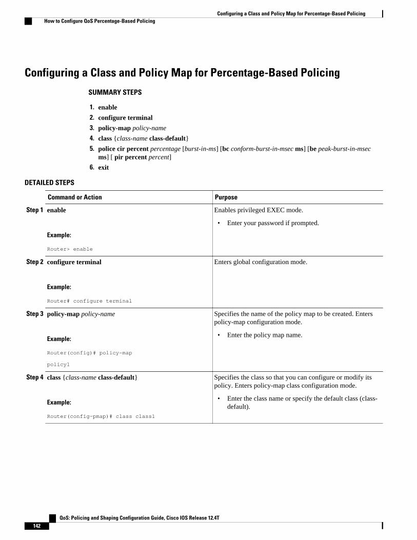
Configuring a Class and Policy Map for Percentage-Based Policing
SUMMARY STEPS
1. enable
2. configure terminal
3. policy-map policy-name
4. class {class-name class-default}
5. police cir percent percentage [burst-in-ms] [bc conform-burst-in-msec ms] [be peak-burst-in-msecms] [ pir percent percent]
6. exit
DETAILED STEPS
Command or Action Purpose
Step 1 enable
Example:
Router> enable
Enables privileged EXEC mode.
• Enter your password if prompted.
Step 2 configure terminal
Example:
Router# configure terminal
Enters global configuration mode.
Step 3 policy-map policy-name
Example:
Router(config)# policy-map policy1
Specifies the name of the policy map to be created. Enterspolicy-map configuration mode.
• Enter the policy map name.
Step 4 class {class-name class-default}
Example:
Router(config-pmap)# class class1
Specifies the class so that you can configure or modify itspolicy. Enters policy-map class configuration mode.
• Enter the class name or specify the default class (class-default).
Configuring a Class and Policy Map for Percentage-Based Policing How to Configure QoS Percentage-Based Policing
QoS: Policing and Shaping Configuration Guide, Cisco IOS Release 12.4T142

Command or Action Purpose
Step 5 police cir percent percentage [burst-in-ms] [bc conform-burst-in-msec ms] [be peak-burst-in-msec ms] [ pir percent percent]
Example:
Router(config-pmap-c)# police cir percent 20 bc 300 ms be 400 ms pir percent 40
Configures traffic policing on the basis of the specifiedbandwidth percentage and optional burst sizes. Enterspolicy-map class police configuration mode.
• Enter the bandwidth percentage and optional burstsizes.
Step 6 exit
Example:
Router(config-pmap-c-police)# exit
Exits policy-map class police configuration mode.
Attaching the Policy Map to an Interface for Percentage-Based Policing
SUMMARY STEPS
1. enable
2. configure terminal
3. interface type number
4. pvc [name] vpi / vci [ilmi | qsaal | smds]
5. service-policy {input| output} policy-map-name
6. exit
DETAILED STEPS
Command or Action Purpose
Step 1 enable
Example:
Router> enable
Enables privileged EXEC mode.
• Enter your password if prompted.
Step 2 configure terminal
Example:
Router# configure terminal
Enters global configuration mode.
Attaching the Policy Map to an Interface for Percentage-Based PolicingHow to Configure QoS Percentage-Based Policing
QoS: Policing and Shaping Configuration Guide, Cisco IOS Release 12.4T 143

Command or Action Purpose
Step 3 interface type number
Example:
Router(config)# interface serial4/0
Configures an interface (or subinterface) type and enters interfaceconfiguration mode.
• Enter the interface type number.
Note Depending on the needs of your network, you may need to attach thepolicy map to a subinterface, an ATM PVC, a Frame Relay DLCI, orother type of interface.
Step 4 pvc [name] vpi / vci [ilmi | qsaal | smds]
Example:
Router(config-if)# pvc cisco 0/16 ilmi
(Optional) Creates or assigns a name to an ATM PVC and specifies theencapsulation type on an ATM PVC. Enters ATM VC configuration mode.
Note This step is required only if you are attaching the policy map to anATM PVC. If you are not attaching the policy map to an ATM PVC,skip this step and proceed with Attaching the Policy Map to anInterface for Percentage-Based Policing, page 143.
Step 5 service-policy {input| output} policy-map-name
Example:
Router(config-if)# service-policy input policy1
Example:
Specifies the name of the policy map to be attached to the input or outputdirection of the interface.
Note Policy maps can be configured on ingress or egress routers. They canalso be attached in the input or output direction of an interface. Thedirection (input or output) and the router (ingress or egress) to whichthe policy map should be attached varies according your networkconfiguration. When using the service-policy command to attach thepolicy map to an interface, be sure to choose the router and theinterface direction that are appropriate for your network configuration.
• Enter the policy map name.
Step 6 exit
Example:
Router(config-if)# exit
(Optional) Exits interface configuration mode.
Verifying the Percentage-Based Policing Configuration
SUMMARY STEPS
1. enable
2. show class-map [class-map-name]
3. show policy-map interface interface-name
4. exit
Verifying the Percentage-Based Policing Configuration How to Configure QoS Percentage-Based Policing
QoS: Policing and Shaping Configuration Guide, Cisco IOS Release 12.4T144

DETAILED STEPS
Command or Action Purpose
Step 1 enable
Example:
Router> enable
Enables privileged EXEC mode.
• Enter your password if prompted.
Step 2 show class-map [class-map-name]
Example:
Router# show class-map class1
Displays all information about a class map, including the match criterion.
• Enter class map name.
Step 3 show policy-map interface interface-name
Example:
Router# show policy-map interface serial4/0
Displays the packet statistics of all classes that are configured for all servicepolicies either on the specified interface or subinterface or on a specific PVCon the interface.
• Enter the interface name.
Step 4 exit
Example:
Router# exit
(Optional) Exits privileged EXEC mode.
• Troubleshooting Tips for Percentage-Based Policing, page 145
Troubleshooting Tips for Percentage-Based PolicingThe commands in the Verifying the Percentage-Based Policing Configuration, page 144 section allow youto verify that you achieved the intended configuration and that the feature is functioning correctly. If, afterusing the show commands listed above, you find that the configuration is not correct or the feature is notfunctioning as expected, perform these operations:
If the configuration is not the one you intended, complete the following procedures:
1 Use the show running-config command and analyze the output of the command.2 If the policy map does not appear in the output of the show running-config command, enable the
logging console command.3 Attach the policy map to the interface again.
If the packets are not being matched correctly (for example, the packet counters are not incrementingcorrectly), complete the following procedures:
1 Run the show policy-mapcommand and analyze the output of the command.2 Run the show running-config command and analyze the output of the command.
QoS Percentage-Based PolicingTroubleshooting Tips for Percentage-Based Policing
QoS: Policing and Shaping Configuration Guide, Cisco IOS Release 12.4T 145

3 Use the show policy-map interface command and analyze the output of the command. Check the thefollowing findings:
a If a policy map applies queueing, and the packets are matching the correct class, but you seeunexpected results, compare the number of the packets in the queue with the number of the packetsmatched.
b If the interface is congested, and only a small number of the packets are being matched, check thetuning of the transmission (tx) ring, and evaluate whether the queueing is happening on the tx ring.To do this, use the show controllers command, and look at the value of the tx count in the output ofthe command.
Configuration Examples for QoS Percentage-Based Policing• Specifying Traffic Policing on the Basis of a Bandwidth Percentage Example, page 146
• Verifying the Percentage-Based Policing Configuration Example, page 146
Specifying Traffic Policing on the Basis of a Bandwidth PercentageExample
The following example configures traffic policing using a committed information rate (CIR) and a peakinformation rate (PIR) on the basis of a percentage of bandwidth. In this example, a CIR of 20 percent anda PIR of 40 percent have been specified. Additionally, an optional bc value and be value (300 ms and 400ms, respectively) have been specified.
Router> enableRouter# configure terminalRouter(config)# policy-map policy1Router(config-pmap)# class class1Router(config-pmap-c)# police cir percent 20 bc 300 ms be 400 ms pir percent 40 Router(config-pmap-c-police)# exit
After the policy map and class maps are configured, the policy map is attached to interface as shown in thefollowing example.
Router> enableRouter# configure terminalRouter(config-if)# interface serial4/0 Router(config-if)# service-policy input policy1Router(config-if)# exit
Verifying the Percentage-Based Policing Configuration ExampleThis section contains sample output from the show policy-map interface command and the show policy-map command. The output from these commands can be used to verify and monitor the featureconfiguration on your network.
The following is sample output from the show policy-map command. This sample output displays thecontents of a policy map called "policy1." In policy 1, traffic policing on the basis of a CIR of 20 percent
Specifying Traffic Policing on the Basis of a Bandwidth Percentage Example Configuration Examples for QoS Percentage-Based Policing
QoS: Policing and Shaping Configuration Guide, Cisco IOS Release 12.4T146

has been configured, and the bc and be have been specified in milliseconds. As part of the traffic policingconfiguration, optional conform, exceed, and violate actions have been specified.
Router# show policy-map policy1 Policy Map policy1 Class class1 police cir percent 20 bc 300 ms pir percent 40 be 400 ms conform-action transmit exceed-action drop violate-action drop
The following is sample output from the show policy-map interface command. This sample displays thestatistics for the serial 2/0 interface on which traffic policing has been enabled. The committed burst (bc)and excess burst (be) are specified in milliseconds (ms).
Router# show policy-map interface serial2/0 Serial2/0 Service-policy output: policy1 (1050) Class-map: class1 (match-all) (1051/1) 0 packets, 0 bytes 5 minute offered rate 0 bps, drop rate 0 bps Match: ip precedence 0 (1052) police: cir 20 % bc 300 ms cir 409500 bps, bc 15360 bytes pir 40 % be 400 ms pir 819000 bps, be 40960 bytes conformed 0 packets, 0 bytes; actions: transmit exceeded 0 packets, 0 bytes; actions: drop violated 0 packets, 0 bytes; actions: drop conformed 0 bps, exceed 0 bps, violate 0 bps Class-map: class-default (match-any) (1054/0) 0 packets, 0 bytes 5 minute offered rate 0 bps, drop rate 0 bps Match: any (1055) 0 packets, 0 bytes 5 minute rate 0 bps
In this example, the CIR and PIR are displayed in bps, and both the committed burst (bc) and excess burst(be) are displayed in bits.
The CIR, PIR bc, and be are calculated on the basis of the formulas described below.
Formula for Calculating the CIR
When calculating the CIR, the following formula is used:
• CIR percentage specified (as shown in the output of the show policy-mapcommand) * bandwidth(BW) of the interface (as shown in the output of the show interfaces command) = total bits per second
On serial interface 2/0, the bandwidth (BW) is 2048 kbps. To see the bandwidth of the interface, use theshow interfaces command. A sample is shown below:
Router# show interfaces serial2/0Serial2/0 is administratively down, line protocol is down Hardware is M4T MTU 1500 bytes, BW 2048 Kbit, DLY 20000 usec, rely 255/255, load 1/255
The following values are used for calculating the CI:.
20 % * 2048 kbps = 409600 bps
QoS Percentage-Based PolicingConfiguration Examples for QoS Percentage-Based Policing
QoS: Policing and Shaping Configuration Guide, Cisco IOS Release 12.4T 147

Formula for Calculating the PIR
When calculating the PIR, the following formula is used:
• PIR percentage specified (as shown in the output of the show policy-mapcommand) * bandwidth(BW) of the interface (as shown in the output of the show interfaces command) = total bits per second
On serial interface 2/0, the bandwidth (BW) is 2048 kbps. To see the bandwidth of the interface, use theshow interfaces command. A sample is shown below:
Router# show interfaces serial2/0Serial2/0 is administratively down, line protocol is down Hardware is M4T MTU 1500 bytes, BW 2048 Kbit, DLY 20000 usec, rely 255/255, load 1/255
The following values are used for calculating the PIR:
40 % * 2048 kbps = 819200 bps
Note Discrepancies between this total and the total shown in the output of the show policy-map interfacecommand can be attributed to a rounding calculation or to differences associated with the specific interfaceconfiguration.
Formula for Calculating the Committed Burst (bc)
When calculating the bc, the following formula is used:
• The bc in milliseconds (as shown in the show policy-map command) * the CIR in bits per seconds =total number bytes
The following values are used for calculating the bc:
300 ms * 409600 bps = 15360 bytes
Formula for Calculating the Excess Burst (be)
When calculating the bc and the be, the following formula is used:
• The be in milliseconds (as shown in the show policy-map command) * the PIR in bits per seconds =total number bytes
The following values are used for calculating the be:
400 ms * 819200 bps = 40960 bytes
Additional ReferencesThe following sections provide references related to the QoS Percentage-Based Policing feature.
QoS Percentage-Based Policing Additional References
QoS: Policing and Shaping Configuration Guide, Cisco IOS Release 12.4T148

Related Documents
Related Topic Document Title
QoS commands: complete command syntax,command modes, command history, defaults, usageguidelines, and examples
Cisco IOS Quality of Service Solutions CommandReference
Modular QoS Command-Line Interface (CLI)(MQC), including information about attachingpolicy maps
"Applying QoS Features Using the MQC" module
Traffic shaping and traffic policing "Policing and Shaping Overview" module
Commands related to dCEF Cisco IOS Switching Command Reference
Standard
Standard Title
No new or modified standards are supported by thisfeature, and support for existing standards has notbeen modified by this feature.
--
MIB
MIB MIBs Link
No new or modified MIBs are supported by thisfeature, and support for existing MIBs has not beenmodified by this feature.
To locate and download MIBs for selectedplatforms, Cisco IOS releases, and feature sets, useCisco MIB Locator found at the following URL:
http://www.cisco.com/go/mibs
RFCs
RFC Title
RFC 2697 A Single Rate Three Color Marker
RFC 2698 A Two Rate Three Color Marker
QoS Percentage-Based PolicingAdditional References
QoS: Policing and Shaping Configuration Guide, Cisco IOS Release 12.4T 149
Technical Assistance
Description Link
The Cisco Support and Documentation websiteprovides online resources to downloaddocumentation, software, and tools. Use theseresources to install and configure the software andto troubleshoot and resolve technical issues withCisco products and technologies. Access to mosttools on the Cisco Support and Documentationwebsite requires a Cisco.com user ID andpassword.
http://www.cisco.com/cisco/web/support/index.html
Feature Information for QoS Percentage-Based PolicingThe following table provides release information about the feature or features described in this module.This table lists only the software release that introduced support for a given feature in a given softwarerelease train. Unless noted otherwise, subsequent releases of that software release train also support thatfeature.
Use Cisco Feature Navigator to find information about platform support and Cisco software image support.To access Cisco Feature Navigator, go to www.cisco.com/go/cfn. An account on Cisco.com is not required.
QoS Percentage-Based Policing Feature Information for QoS Percentage-Based Policing
QoS: Policing and Shaping Configuration Guide, Cisco IOS Release 12.4T150
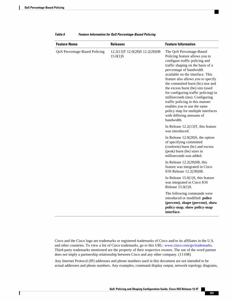
Table 6 Feature Information for QoS Percentage-Based Policing
Feature Name Releases Feature Information
QoS Percentage-Based Policing 12.2(13)T 12.0(28)S 12.2(28)SB15.0(1)S
The QoS Percentage-BasedPolicing feature allows you toconfigure traffic policing andtraffic shaping on the basis of apercentage of bandwidthavailable on the interface. Thisfeature also allows you to specifythe committed burst (bc) size andthe excess burst (be) size (usedfor configuring traffic policing) inmilliseconds (ms). Configuringtraffic policing in this mannerenables you to use the samepolicy map for multiple interfaceswith differing amounts ofbandwidth.
In Release 12.2(13)T, this featurewas introduced.
In Release 12.0(28)S, the optionof specifying committed(conform) burst (bc) and excess(peak) burst (be) sizes inmilliseconds was added.
In Release 12.2(28)SB, thisfeature was integrated in CiscoIOS Release 12.2(28)SB.
In Release 15.0(1)S, this featurewas integrated in Cisco IOSRelease 15.0(1)S.
The following commands wereintroduced or modified: police(percent), shape (percent), showpolicy-map, show policy-mapinterface.
Cisco and the Cisco logo are trademarks or registered trademarks of Cisco and/or its affiliates in the U.S.and other countries. To view a list of Cisco trademarks, go to this URL: www.cisco.com/go/trademarks.Third-party trademarks mentioned are the property of their respective owners. The use of the word partnerdoes not imply a partnership relationship between Cisco and any other company. (1110R)
Any Internet Protocol (IP) addresses and phone numbers used in this document are not intended to beactual addresses and phone numbers. Any examples, command display output, network topology diagrams,
QoS Percentage-Based Policing
QoS: Policing and Shaping Configuration Guide, Cisco IOS Release 12.4T 151

and other figures included in the document are shown for illustrative purposes only. Any use of actual IPaddresses or phone numbers in illustrative content is unintentional and coincidental.
QoS Percentage-Based Policing
QoS: Policing and Shaping Configuration Guide, Cisco IOS Release 12.4T152