Embed Size (px)
Citation preview

LS1020AQorIQ LS1020A Data SheetFeatures
• Arm® Cortex®-A7 MPCore compliant with Armv7-A™ architecture
• LS1020A contains a dual-core Cortex-A7. Each coreincludes:– 32 KB L1 Instruction Cache (ECC protection)– 32 KB L1 Data Cache (ECC protection)– NEON Co-processor– Floating Point (FPU)– QorIQ Trust Architecture and Arm TrustZone®
• Snoop Control Unit (SCU)
• 512 KB unified I/D L2 Cache (ECC protection)
• Hierarchical interconnect fabric– The platform has a single 128-bit AMBA 4 AXI
Coherency Extensions (ACE) master port, whichconnects to CCI-400 Interconnect.
• One 8/16/32-bit DDR3L/DDR4 SDRAM memorycontrollers– ECC and interleaving support
• VeTSEC Ethernet complex– Up to 3x Gigabit Ethernet– MII, RMII, RGMII, and SGMII support– QoS, lossless flow control, and IEEE® 1588
• Up to 4 SerDes lanes for high-speed peripheralinterfaces– Two PCI Express Gen2 controllers– One Serial ATA 3.0 (SATA 1.5, 3.0, 6.0 Gbps)
controller– Two SGMII interfaces supporting 1000 Mbps
• Integrated audio block– Four synchronous audio interfaces (SAI)– I2S, AC97, and Codec/DSP interfaces– Sony/Philips Digital Interconnect Format (S/PDIF)– Asynchronous Sample Rate Converter (ASRC)
• Additional peripheral interfaces– One high-speed USB 3.0 controller with integrated
PHY– One high-speed USB 2.0 controller with ULPI– Enhanced secure digital host controller
(eSDHC/MMC/eMMC)– Three I2C controllers– FlexTimer/PWM– SPI interface– QuadSPI controller– Two DUARTs– Six LPUART interfaces– Integrated flash controller supporting NAND and
NOR flash– TDM interface– Four GPIO controllers supporting up to 109 general
purpose I/O signals– One 4-channel qDMA controller and one eDMA
controller– Global interrupt controller (GIC)– Thermal monitor unit (TMU)
• QUICC Engine ULite block– 32-bit RISC controller for flexible support of the
communications peripherals– Serial DMA channel for receive and transmit on all
serial channels– Two universal communication controllers (TDM
and HDLC) supporting 64 multichannels, eachrunning at 64 Kbps
• 525 FC-PBGA package, 19 mm x 19 mm
NXP Semiconductors Document Number LS1020A
Data Sheet: Technical Data Rev. 6, 09/2017
NXP reserves the right to change the production detail specifications as may berequired to permit improvements in the design of its products.

Table of Contents1 Introduction.......................................................................................... 3
2 Pin assignments.................................................................................... 4
2.1 LS1020A Ball Map and Pin List............................................... 4
3 Electrical characteristics.......................................................................48
3.1 Overall DC electrical characteristics......................................... 48
3.2 Power sequencing......................................................................54
3.3 Power-down requirements.........................................................58
3.4 Power characteristics................................................................. 58
3.5 I/O DC power supply recommendation.....................................60
3.6 Power-on ramp rate................................................................... 63
3.7 Input clocks............................................................................... 64
3.8 RESET initialization..................................................................70
3.9 DDR3L and DDR4 SDRAM controller.................................... 71
3.10 DUART interface...................................................................... 77
3.11 Ethernet interface, Ethernet management interface, IEEE Std
1588........................................................................................... 79
3.12 QUICC engine specifications....................................................96
3.13 USB 2.0 interface...................................................................... 102
3.14 USB 3.0 interface...................................................................... 105
3.15 Integrated flash controller (IFC)................................................109
3.16 LPUART interface.....................................................................118
3.17 Flextimer interface.....................................................................120
3.18 SAI/I2S interface.......................................................................122
3.19 SPDIF interface......................................................................... 125
3.20 SPI interface.............................................................................. 127
3.21 QuadSPI interface......................................................................133
3.22 Enhanced secure digital host controller (eSDHC).....................135
3.23 JTAG controller.........................................................................144
3.24 I2C interface.............................................................................. 147
3.25 GPIO interface...........................................................................150
3.26 GIC interface............................................................................. 152
3.27 High-speed serial interfaces (HSSI).......................................... 154
4 Hardware design considerations...........................................................175
4.1 Power supply design..................................................................175
4.2 Decoupling recommendations...................................................180
4.3 SerDes block power supply decoupling recommendations.......181
4.4 Connection recommendations................................................... 181
4.5 Thermal......................................................................................186
4.6 Recommended thermal model...................................................187
4.7 Temperature diode.....................................................................187
4.8 Thermal management information............................................ 187
5 Package information.............................................................................191
5.1 Mechanical dimensions of the FC-PBGA (no lid).................... 191
5.2 Mechanical dimensions of the FC-PBGA (with lid)................. 193
6 Security fuse processor.........................................................................195
7 Ordering information............................................................................195
7.1 Part numbering nomenclature....................................................195
7.2 Orderable part numbers addressed by this document................196
8 Revision history....................................................................................198
QorIQ LS1020A Data Sheet, Rev. 6, 09/2017
2 NXP Semiconductors

1 IntroductionA member of the Layerscape (LS1) series, the LS102xA family is a cost-effective,power-efficient, and highly integrated system-on-chip (SoC) design that extends thereach of the NXP value-performance line of QorIQ communications processors.Featuring a pair of extremely power-efficient 32-bit Arm® Cortex®-A7 cores with ECC-protected L1 and L2 cache memories for high reliability, running up to 1 GHz, andproviding pre-silicon CoreMark® performance of over 5,000, the LS102xA familydelivers greater performance than any previous sub-4W communication processor.
This chip can be used for networking and wireless access points, industrial gateways,industrial automation, printing, imaging, and M2M for enterprise and consumernetworking and router applications.
This figure shows the block diagram of the LS1020A chip.
Introduction
QorIQ LS1020A Data Sheet, Rev. 6, 09/2017
NXP Semiconductors 3

QorIQ LS1020A Processor Block Diagram
DDR3L/4Memory
Controller
Security(XoR,CRC)
128 KBSRAM
512 KB Coherent L2 Cache
32 KBD Cache
32 KBI Cache
32 KBD Cache
32 KBI Cache
System Interfaces
System Control
IFC Flash
QuadSPI Flash
1x SD/MMC
2x DUART, 6x LPUART
Internal Boot ROM
Security Monitor
Security Fuses
Power Management
eDMA
3x I 2 C, 2x SPI, 4x GPIO
USB 2.0
8x FlexTimer/PWM
USB 3.0 w/ PHY
Audio Subsystem:4x SAI, ASRC, SPDIF
Eth
erne
t
Eth
erne
t
PC
Ie 2
.0
PC
Ie 2
.0
4-Lane 6 GHz SerDes
SAT
A 3
.0
Core Complex Basic Peripherals and Interconnect
Accelerators and Memory Control Networking Elements
Arm ®
Cortex ®-A7Core
NEONFPU
Arm ®
Cortex ®-A7Core
NEONFPU
qDMACache Coherent Interconnect (CCI-400)
SMMU SMMU SMMU SMMU
Eth
erne
t
2x WDOG
GIC-400
TMU
(HDLC,TDM,PB)
QUICCEngine
Figure 1. LS1020A block diagram
2 Pin assignments
LS1020A Ball Map and Pin List
2.1.1 525 ball layout diagrams
This figure shows the complete view of the LS1020A ball map diagram. Figure 3, Figure4, Figure 5, and Figure 6 show quadrant views.
2.1
Pin assignments
QorIQ LS1020A Data Sheet, Rev. 6, 09/2017
4 NXP Semiconductors

1 2 3 4 5 6 7 8 9 10 11 12 13 14 15 16 17 18 19 20 21 22 23
1 2 3 4 5 6 7 8 9 10 11 12 13 14 15 16 17 18 19 20 21 22 23
A
B
C
D
E
F
G
H
J
K
L
M
N
P
R
T
U
V
W
Y
AA
AB
AC
A
B
C
D
E
F
G
H
J
K
L
M
N
P
R
T
U
V
W
Y
AA
AB
AC
DDR Interface 1 IFC DUART I2C eSDHC
Interrupts Trust System Control ASLEEP SYSCLK
DDR Clocking RTC DIFF_SYSCLK Debug DFT
JTAG Analog Signals Serdes 1 USB PHY Ethernet MI 1
Ethernet Cont. 1 Ethernet Cont. 2 Ethernet Cont. 3 QE TDM eSDHC
Power Ground No Connects Reserved
SEE DETAIL A SEE DETAIL B
SEE DETAIL C SEE DETAIL D
Figure 2. Complete BGA Map for the LS1020A
LS1020A Ball Map and Pin List
QorIQ LS1020A Data Sheet, Rev. 6, 09/2017
NXP Semiconductors 5

1 2 3 4 5 6 7 8 9 10 11 12
1 2 3 4 5 6 7 8 9 10 11 12
A
B
C
D
E
F
G
H
J
K
L
M
A
B
C
D
E
F
G
H
J
K
L
M
IFC_AD00
IFC_AD01
IFC_AD02
IFC_AD03
IFC_AD04
IFC_AD05
IFC_AD06
IFC_AD07
IFC_AD08
IFC_AD09
IFC_A16
IFC_A17
IFC_A18
IFC_A19
IFC_A20
IFC_A21
IFC_A22
IFC_A23
IFC_A24
IFC_A25
UART1_SIN
IIC2_SCL
IIC2_SDA
SDHC_CMD
SDHC_DAT0
SDHC_DAT1
SDHC_DAT2
SDHC_DAT3
SDHC_CLK
IRQ0 IRQ1
IRQ4
IRQ5
EVT9_B
TA_TMP_
DETECT_B
PORESET_B
HRESET_B
RESET_REQ_B
ASLEEP
SYSCLK
RTC
EVT0_B
EVT1_B
EVT2_B
EVT3_B
EVT4_B
CKSTP_OUT_B
CLK_OUT
SCAN_MODE_B
TEST_SEL_B
TCKTDI
TDO TMSTRST_B
TD1_ANODE
TD1_CATHODE
FA_ANALOG_
PIN
USB1_D_P
USB1_D_M
USB1_VBUS
USB1_ID
USB1_TX_
P
USB1_TX_M
USB1_RX_
P
USB1_RX_
M
USB1_RESREF
TDMA_RXD
TDMA_RSYNC
TDMA_TXD
TDMA_TSYNC
TDMA_RQ
TDMB_RXD
TDMB_RSYNC
TDMB_TXD
TDMB_TSYNC
TDMB_RQ CLK09
CLK10
CLK11
SDHC_DAT4
SDHC_DAT5
SDHC_DAT6
SDHC_DAT7
DIFF_SYSCLK
DIFF_SYSCLK_B
NC_L6
NC_M6
DDR Interface 1 IFC DUART I2C eSDHC
Interrupts Trust System Control ASLEEP SYSCLK
DDR Clocking RTC DIFF_SYSCLK Debug DFT
JTAG Analog Signals Serdes 1 USB PHY Ethernet MI 1
Ethernet Cont. 1 Ethernet Cont. 2 Ethernet Cont. 3 QE TDM eSDHC
GND001 GND002
GND005 GND006 GND007 GND008 GND009
GND014 GND015
GND018 GND019
GND022 GND023 GND024
GND030 GND031
GND034 GND035 GND036 GND037 GND038 GND039 GND040
GND050 GND051 GND052 GND053
GND058 GND059 GND060 GND061
GND066 GND067 GND068
O1VDD1 O1VDD2 OVDD
D1VDD
DVDD1 DVDD2
EVDD
FA_VL
PROG_MTR
TA_PROG_
SFP
VDD01
VDD03
VDD05
VDDC1
VDDC2
AVDD_CGA1
AVDD_PLAT
USB_HVDD
USB1_SDVDD
USB1_SPVDD
USB1_SXVDD
Power Ground No Connects Reserved
Figure 3. Detail A
LS1020A Ball Map and Pin List
QorIQ LS1020A Data Sheet, Rev. 6, 09/2017
6 NXP Semiconductors

12 13 14 15 16 17 18 19 20 21 22 23
12 13 14 15 16 17 18 19 20 21 22 23
A
B
C
D
E
F
G
H
J
K
L
M
A
B
C
D
E
F
G
H
J
K
L
M
D1_MDQ00
D1_MDQ01
D1_MDQ04
D1_MDQ05
D1_MDQ08
D1_MDQ09
D1_MDQ12
D1_MDQ13
D1_MDQ16
D1_MDQ17
D1_MDQ18
D1_MDQ19
D1_MDQ20
D1_MDQ21
D1_MDQ22
D1_MDQ23
D1_MDQ24
D1_MDQ25
D1_MDQ26
D1_MDQ27
D1_MDQ28
D1_MDQ29
D1_MDQ30
D1_MDQ31
D1_MECC0
D1_MECC1
D1_MECC2
D1_MECC3
D1_MDM0
D1_MDM1
D1_MDM2
D1_MDM3
D1_MDM8
D1_MDQS1
D1_MDQS2
D1_MDQS3
D1_MDQS8
D1_MDQS1_B
D1_MDQS2_B
D1_MDQS3_B
D1_MDQS8_B
IFC_AD08
IFC_AD09
IFC_AD10
IFC_AD11
IFC_AD12
IFC_AD13
IFC_AD14
IFC_AD15
IFC_A24
IFC_A25
IFC_A26
IFC_A27
IFC_PAR0
IFC_PAR1
IFC_CS0_B
IFC_CS1_B
IFC_CS2_B
IFC_CS3_B
IFC_WE0_B
IFC_BCTL
IFC_TE
IFC_NDDQS
IFC_AVD
IFC_CLE
IFC_OE_B
IFC_WP0_B
IFC_RB0_B
IFC_RB1_B
IFC_PERR_B
IFC_CLK0
IFC_CLK1
IFC_NDDDR_
CLK
DDRCLK
D1_MVREF
FA_ANALOG_
PIN
FA_ANALOG_
G_VTH_TPA
NC_F19
NC_G18
NC_H19
NC_J17
SPARE1
SPARE2
DDR Interface 1 IFC DUART I2C eSDHC
Interrupts Trust System Control ASLEEP SYSCLK
DDR Clocking RTC DIFF_SYSCLK Debug DFT
JTAG Analog Signals Serdes 1 USB PHY Ethernet MI 1
Ethernet Cont. 1 Ethernet Cont. 2 Ethernet Cont. 3 QE TDM eSDHC
GND003 GND004
GND010 GND011 GND012 GND013
GND016 GND017
GND020 GND021
GND024 GND025 GND026 GND027
GND028 GND029
GND032 GND033
GND040 GND041 GND042 GND043 GND044 GND045
GND046 GND047 GND048 GND049
GND054 GND055 GND056 GND057
GND061 GND062 GND063 GND064 GND065
GND069 GND070 GND071 GND072 GND073
SENSEGND
OVDD BVDD1 BVDD2 BVDD3
G1VDD01
G1VDD02
G1VDD03
FA_VL
TH_VDD
VDD01 VDD02
VDD04
VDD05 VDD06
AVDD_D1
SENSEVDD
Power Ground No Connects Reserved
Figure 4. Detail B
LS1020A Ball Map and Pin List
QorIQ LS1020A Data Sheet, Rev. 6, 09/2017
NXP Semiconductors 7

1 2 3 4 5 6 7 8 9 10 11 12
1 2 3 4 5 6 7 8 9 10 11 12
M
N
P
R
T
U
V
W
Y
AA
AB
AC
M
N
P
R
T
U
V
W
Y
AA
AB
AC
UART1_SOUT
UART2_SOUT
UART1_SIN
UART2_SIN
UART1_RTS_B
UART2_RTS_B
UART1_CTS_B
UART2_CTS_B
IIC1_SCL
IIC1_SDA
IRQ2
IRQ3
IRQ5
TA_BB_TMP_
DETECT_B
SD1_TX0_
P
SD1_TX1_
P
SD1_TX0_
N
SD1_TX1_
N
SD1_RX0_
P
SD1_RX1_
P
SD1_RX0_
N
SD1_RX1_
N
SD1_REF_
CLK1_P
SD1_REF_
CLK1_N
SD1_IMP_
CAL_RX
SD1_PLL1_TPA
SD1_PLL1_TPD
EMI1_MDC
EMI1_MDIO
EC1_TXD3
EC1_TXD2
EC1_TXD1
EC1_TXD0
EC1_TX_EN
EC1_GTX_CLK
EC1_GTX_
CLK125
EC1_RXD3
EC1_RXD2
EC1_RXD1
EC1_RXD0
EC1_RX_CLK
EC1_RX_DV
EC2_TXD3
EC2_TXD2
EC2_TXD1
EC2_TXD0
EC2_TX_EN
EC2_GTX_CLK
EC2_GTX_
CLK125
EC2_RXD3
EC2_RXD2
EC2_RXD1
EC2_RXD0
EC2_RX_CLK
EC2_RX_DV
EC3_TXD3
EC3_TXD2
EC3_TXD1
EC3_TXD0
EC3_TX_EN
EC3_GTX_CLK
EC3_GTX_
CLK125
EC3_RXD3
EC3_RXD2
EC3_RXD1
EC3_RXD0
EC3_RX_CLK
EC3_RX_DV
TDMB_TXD
TDMB_TSYNC CLK11
CLK12
TA_BB_RTC
NC_M6
NC_V7
DDR Interface 1 IFC DUART I2C eSDHC
Interrupts Trust System Control ASLEEP SYSCLK
DDR Clocking RTC DIFF_SYSCLK Debug DFT
JTAG Analog Signals Serdes 1 USB PHY Ethernet MI 1
Ethernet Cont. 1 Ethernet Cont. 2 Ethernet Cont. 3 QE TDM eSDHC
GND066 GND067 GND068
GND074 GND075 GND076 GND077
GND081 GND082 GND083 GND084
GND090 GND091
GND095 GND096
GND099 GND100
GND102
GND103
GND104
GND106
GND107 GND108
GND109
X1GND01 X1GND02
X1GND05 X1GND06
X1GND08 X1GND09
S1GND01 S1GND02 S1GND03
S1GND06
S1GND07 S1GND08 S1GND09 S1GND10 S1GND11 S1GND12
S1GND18 S1GND19 S1GND20
S1GND23 S1GND24 S1GND25
AGND_SD1_PLL
1SENSEGNDC
D1VDD
L1VDD1
L1VDD2
LVDD1
LVDD2
S1VDD1 S1VDD2
X1VDD1 X1VDD2
X1VDD4
VDD05
VDD07 VDD08
VDD10
VDDC2
VDDC3
VDDC4
TA_BB_VDD
AVDD_SD1_PLL1
SENSEVDDC
Power Ground No Connects Reserved
Figure 5. Detail C
LS1020A Ball Map and Pin List
QorIQ LS1020A Data Sheet, Rev. 6, 09/2017
8 NXP Semiconductors

12 13 14 15 16 17 18 19 20 21 22 23
12 13 14 15 16 17 18 19 20 21 22 23
M
N
P
R
T
U
V
W
Y
AA
AB
AC
M
N
P
R
T
U
V
W
Y
AA
AB
AC
D1_MDQ01
D1_MDQ02
D1_MDQ03
D1_MDQ06
D1_MDQ07
D1_MDQ10
D1_MDQ11
D1_MDQ14
D1_MDQ15
D1_MAPAR_ERR_B
D1_MAPAR_
OUT
D1_MDM0
D1_MDQS0
D1_MDQS1
D1_MDQS0_B
D1_MDQS1_B
D1_MBA0
D1_MBA1
D1_MBA2
D1_MA00
D1_MA01
D1_MA02
D1_MA03
D1_MA04
D1_MA05
D1_MA06
D1_MA07
D1_MA08
D1_MA09
D1_MA10
D1_MA11
D1_MA12
D1_MA13
D1_MA14
D1_MA15
D1_MWE_B
D1_MRAS_B
D1_MCAS_B
D1_MCS0_B
D1_MCS1_B
D1_MCS2_B
D1_MCS3_B
D1_MCKE0
D1_MCKE1
D1_MCK0
D1_MCK1
D1_MCK0_B
D1_MCK1_B
D1_MODT0
D1_MODT1
D1_MDIC0
D1_MDIC1
D1_TPA
SD1_TX2_
P
SD1_TX3_
P
SD1_TX2_
N
SD1_TX3_
N
SD1_RX2_
P
SD1_RX3_
P
SD1_RX2_
N
SD1_RX3_
N
SD1_REF_
CLK2_P
SD1_REF_
CLK2_N
SD1_IMP_
CAL_TX
SD1_PLL2_TPA
SD1_PLL2_TPD
NC_U16
NC_V16
NC_W16
NC_W17
NC_DET
DDR Interface 1 IFC DUART I2C eSDHC
Interrupts Trust System Control ASLEEP SYSCLK
DDR Clocking RTC DIFF_SYSCLK Debug DFT
JTAG Analog Signals Serdes 1 USB PHY Ethernet MI 1
Ethernet Cont. 1 Ethernet Cont. 2 Ethernet Cont. 3 QE TDM eSDHC
GND069 GND070 GND071 GND072 GND073
GND077 GND078 GND079 GND080
GND085 GND086 GND087 GND088 GND089
GND092 GND093 GND094
GND097 GND098
GND101
GND105
X1GND03 X1GND04
X1GND06 X1GND07
X1GND09 X1GND10
S1GND03 S1GND04 S1GND05
S1GND06
S1GND12 S1GND13 S1GND14 S1GND15 S1GND16 S1GND17
S1GND20 S1GND21 S1GND22
S1GND25 S1GND26 S1GND27
AGND_SD1_PLL
2
G1VDD03
G1VDD04
G1VDD05 G1VDD06 G1VDD07
G1VDD08 G1VDD09
G1VDD10 G1VDD11
G1VDD12 G1VDD13 G1VDD14
G1VDD15 G1VDD16 G1VDD17
G1VDD18 G1VDD19 G1VDD20
S1VDD2 S1VDD3
X1VDD2 X1VDD3
VDD05 VDD06
VDD09
VDD10 VDD11
AVDD_SD1_PLL2
Power Ground No Connects Reserved
Figure 6. Detail D
LS1020A Ball Map and Pin List
QorIQ LS1020A Data Sheet, Rev. 6, 09/2017
NXP Semiconductors 9

2.1.2 Pinout list
This table provides the pinout listing for the LS1020A by bus. Primary functions arebolded in the table.
Table 1. Pinout list by bus
Signal Signal description Packagepin
number
Pintype
Power supply Notes
DDR SDRAM Memory Interface 1
D1_MA00 Address AC22 O G1VDD ---
D1_MA01 Address Y19 O G1VDD ---
D1_MA02 Address V21 O G1VDD ---
D1_MA03 Address AC20 O G1VDD ---
D1_MA04 Address AA20 O G1VDD ---
D1_MA05 Address W20 O G1VDD ---
D1_MA06 Address AB21 O G1VDD ---
D1_MA07 Address U20 O G1VDD ---
D1_MA08 Address T20 O G1VDD ---
D1_MA09 Address Y21 O G1VDD ---
D1_MA10 Address AA19 O G1VDD ---
D1_MA11 Address U21 O G1VDD ---
D1_MA12 Address AA18 O G1VDD ---
D1_MA13 Address T21 O G1VDD ---
D1_MA14 Address AC19 O G1VDD ---
D1_MA15 Address R18 O G1VDD ---
D1_MAPAR_ERR_B Address Parity Error W21 I G1VDD 1, 6
D1_MAPAR_OUT Address Parity Out U22 O G1VDD ---
D1_MBA0 Bank Select AC21 O G1VDD ---
D1_MBA1 Bank Select AA21 O G1VDD ---
D1_MBA2 Bank Select AB19 O G1VDD ---
D1_MCAS_B Column Address Strobe W18 O G1VDD ---
D1_MCK0 Clock AA22 O G1VDD ---
D1_MCK0_B Clock Complement AA23 O G1VDD ---
D1_MCK1 Clock W22 O G1VDD ---
D1_MCK1_B Clock Complement W23 O G1VDD ---
D1_MCKE0 Clock Enable V19 O G1VDD 2
D1_MCKE1 Clock Enable U18 O G1VDD 2
D1_MCS0_B Chip Select U19 O G1VDD ---
D1_MCS1_B Chip Select T18 O G1VDD ---
D1_MCS2_B Chip Select V17 O G1VDD ---
Table continues on the next page...
LS1020A Ball Map and Pin List
QorIQ LS1020A Data Sheet, Rev. 6, 09/2017
10 NXP Semiconductors

Table 1. Pinout list by bus (continued)
Signal Signal description Packagepin
number
Pintype
Power supply Notes
D1_MCS3_B Chip Select U17 O G1VDD ---
D1_MDIC0 Driver Impedence Calibration V23 IO G1VDD 3
D1_MDIC1 Driver Impedence Calibration Y23 IO G1VDD 3
D1_MDM0 Data Mask M23 O G1VDD 1
D1_MDM1 Data Mask L20 O G1VDD 1
D1_MDM2 Data Mask E23 O G1VDD 1
D1_MDM3 Data Mask E21 O G1VDD 1
D1_MDM8 Data Mask B21 O G1VDD 1
D1_MDQ00 Data K23 IO G1VDD ---
D1_MDQ01 Data M22 IO G1VDD ---
D1_MDQ02 Data R23 IO G1VDD ---
D1_MDQ03 Data T23 IO G1VDD ---
D1_MDQ04 Data K22 IO G1VDD ---
D1_MDQ05 Data L23 IO G1VDD ---
D1_MDQ06 Data P23 IO G1VDD ---
D1_MDQ07 Data R22 IO G1VDD ---
D1_MDQ08 Data K21 IO G1VDD ---
D1_MDQ09 Data L21 IO G1VDD ---
D1_MDQ10 Data N21 IO G1VDD ---
D1_MDQ11 Data P21 IO G1VDD ---
D1_MDQ12 Data K19 IO G1VDD ---
D1_MDQ13 Data L19 IO G1VDD ---
D1_MDQ14 Data N20 IO G1VDD ---
D1_MDQ15 Data N19 IO G1VDD ---
D1_MDQ16 Data C23 IO G1VDD ---
D1_MDQ17 Data D23 IO G1VDD ---
D1_MDQ18 Data H22 IO G1VDD ---
D1_MDQ19 Data J23 IO G1VDD ---
D1_MDQ20 Data B23 IO G1VDD ---
D1_MDQ21 Data D22 IO G1VDD ---
D1_MDQ22 Data G23 IO G1VDD ---
D1_MDQ23 Data H23 IO G1VDD ---
D1_MDQ24 Data D19 IO G1VDD ---
D1_MDQ25 Data E20 IO G1VDD ---
D1_MDQ26 Data H21 IO G1VDD ---
D1_MDQ27 Data J21 IO G1VDD ---
D1_MDQ28 Data C20 IO G1VDD ---
D1_MDQ29 Data D21 IO G1VDD ---
Table continues on the next page...
LS1020A Ball Map and Pin List
QorIQ LS1020A Data Sheet, Rev. 6, 09/2017
NXP Semiconductors 11

Table 1. Pinout list by bus (continued)
Signal Signal description Packagepin
number
Pintype
Power supply Notes
D1_MDQ30 Data G20 IO G1VDD ---
D1_MDQ31 Data J20 IO G1VDD ---
D1_MDQS0 Data Strobe N23 IO G1VDD ---
D1_MDQS0_B Data Strobe N22 IO G1VDD ---
D1_MDQS1 Data Strobe M19 IO G1VDD ---
D1_MDQS1_B Data Strobe M20 IO G1VDD ---
D1_MDQS2 Data Strobe F23 IO G1VDD ---
D1_MDQS2_B Data Strobe F22 IO G1VDD ---
D1_MDQS3 Data Strobe G21 IO G1VDD ---
D1_MDQS3_B Data Strobe F21 IO G1VDD ---
D1_MDQS8 Data Strobe A21 IO G1VDD ---
D1_MDQS8_B Data Strobe A20 IO G1VDD ---
D1_MECC0 Error Correcting Code B19 IO G1VDD 27
D1_MECC1 Error Correcting Code A19 IO G1VDD 27
D1_MECC2 Error Correcting Code C21 IO G1VDD 27
D1_MECC3 Error Correcting Code B22 IO G1VDD 27
D1_MODT0 On Die Termination R20 O G1VDD 2
D1_MODT1 On Die Termination R19 O G1VDD 2
D1_MRAS_B Row Address Strobe AC18 O G1VDD ---
D1_MWE_B Write Enable W19 O G1VDD ---
Integrated Flash Controller
IFC_A16/QSPI_CS_A0 IFC Address C8 O BVDD 1, 5
IFC_A17/QSPI_CS_A1 IFC Address D8 O BVDD 1, 5
IFC_A18/QSPI_CK_A IFC Address C9 O BVDD 1, 5
IFC_A19/QSPI_CS_B0 IFC Address D9 O BVDD 1, 5
IFC_A20/QSPI_CS_B1 IFC Address C10 O BVDD 1, 5
IFC_A21/QSPI_CK_B/cfg_dram_type
IFC Address D10 O BVDD 1, 4
IFC_A22/QSPI_DIO_A0/IFC_WP1_B
IFC Address C11 O BVDD 1
IFC_A23/QSPI_DIO_A1/IFC_WP2_B
IFC Address D11 O BVDD 1
IFC_A24/QSPI_DIO_A2/IFC_WP3_B
IFC Address C12 O BVDD 1
IFC_A25/GPIO2_25/QSPI_DIO_A3/FTM5_CH0/IFC_RB2_B/IFC_CS4_B
IFC Address D12 O BVDD 1, 6
IFC_A26/GPIO2_26/FTM5_CH1/IFC_RB3_B/IFC_CS5_B
IFC Address C13 O BVDD 1, 6
Table continues on the next page...
LS1020A Ball Map and Pin List
QorIQ LS1020A Data Sheet, Rev. 6, 09/2017
12 NXP Semiconductors

Table 1. Pinout list by bus (continued)
Signal Signal description Packagepin
number
Pintype
Power supply Notes
IFC_A27/GPIO2_27/FTM5_EXTCLK/IFC_CS6_B
IFC Address D13 O BVDD 1, 6
IFC_AD00/cfg_gpinput0 IFC Address / Data A7 IO BVDD 4
IFC_AD01/cfg_gpinput1 IFC Address / Data B8 IO BVDD 4
IFC_AD02/cfg_gpinput2 IFC Address / Data A8 IO BVDD 4
IFC_AD03/cfg_gpinput3 IFC Address / Data B9 IO BVDD 4
IFC_AD04/cfg_gpinput4 IFC Address / Data A9 IO BVDD 4
IFC_AD05/cfg_gpinput5 IFC Address / Data A10 IO BVDD 4
IFC_AD06/cfg_gpinput6 IFC Address / Data B11 IO BVDD 4
IFC_AD07/cfg_gpinput7 IFC Address / Data A11 IO BVDD 4
IFC_AD08/cfg_rcw_src0/SPI1_PCS1
IFC Address / Data B12 IO BVDD 4
IFC_AD09/cfg_rcw_src1/SPI1_PCS2
IFC Address / Data A12 IO BVDD 4
IFC_AD10/cfg_rcw_src2/SPI1_PCS3
IFC Address / Data A13 IO BVDD 4
IFC_AD11/cfg_rcw_src3/SPI1_PCS4
IFC Address / Data B14 IO BVDD 4
IFC_AD12/cfg_rcw_src4/SPI1_PCS5
IFC Address / Data A14 IO BVDD 4
IFC_AD13/cfg_rcw_src5/SPI1_SOUT
IFC Address / Data B15 IO BVDD 4
IFC_AD14/cfg_rcw_src6 IFC Address / Data A15 IO BVDD 4
IFC_AD15/cfg_rcw_src7 IFC Address / Data A16 IO BVDD 4
IFC_AVD IFC Address Valid C16 O BVDD 1, 5
IFC_BCTL IFC Buffer control E14 O BVDD 2
IFC_CLE/cfg_rcw_src8 IFC Command Latch Enable /Write Enable
E17 O BVDD 1, 4
IFC_CLK0 IFC Clock A17 O BVDD 1
IFC_CLK1 IFC Clock B17 O BVDD 1
IFC_CS0_B IFC Chip Select C17 O BVDD 1, 6
IFC_CS1_B/GPIO2_10/SPI1_PCS0/FTM7_CH0
IFC Chip Select D17 O BVDD 1, 6
IFC_CS2_B/GPIO2_11/SPI1_SCK/FTM7_CH1/IIC3_SCL
IFC Chip Select C18 O BVDD 1, 6
IFC_CS3_B/GPIO2_12/QSPI_DIO_B3/IIC3_SDA/FTM7_EXTCLK
IFC Chip Select F18 O BVDD 1, 6
IFC_CS4_B/IFC_A25/GPIO2_25/QSPI_DIO_A3/FTM5_CH0/IFC_RB2_B
IFC Chip Select D12 O BVDD 1
Table continues on the next page...
LS1020A Ball Map and Pin List
QorIQ LS1020A Data Sheet, Rev. 6, 09/2017
NXP Semiconductors 13

Table 1. Pinout list by bus (continued)
Signal Signal description Packagepin
number
Pintype
Power supply Notes
IFC_CS5_B/IFC_A26/GPIO2_26/FTM5_CH1/IFC_RB3_B
IFC Chip Select C13 O BVDD 1
IFC_CS6_B/IFC_A27/GPIO2_27/FTM5_EXTCLK
IFC Chip Select D13 O BVDD 1
IFC_NDDDR_CLK IFC NAND DDR Clock C14 O BVDD 1
IFC_NDDQS IFC DQS Strobe D16 IO BVDD ---
IFC_OE_B/cfg_eng_use1 IFC Output Enable E16 O BVDD 1, 4, 5
IFC_PAR0/GPIO2_13/QSPI_DIO_B0/FTM6_CH0
IFC Address & Data Parity D15 IO BVDD ---
IFC_PAR1/GPIO2_14/QSPI_DIO_B1/FTM6_CH1
IFC Address & Data Parity E13 IO BVDD ---
IFC_PERR_B/GPIO2_15/QSPI_DIO_B2/FTM6_EXTCLK
IFC Parity Error C15 I BVDD 1, 6
IFC_RB0_B IFC Ready / Busy CS0 F16 I BVDD 6
IFC_RB1_B/SPI1_SIN IFC Ready / Busy CS1 F15 I BVDD 6
IFC_RB2_B/IFC_A25/GPIO2_25/QSPI_DIO_A3/FTM5_CH0/IFC_CS4_B
IFC Ready / Busy CS 2 D12 I BVDD 1
IFC_RB3_B/IFC_A26/GPIO2_26/FTM5_CH1/IFC_CS5_B
IFC Ready / Busy CS 3 C13 I BVDD 1
IFC_TE/cfg_ifc_te IFC External TransceiverEnable
D14 O BVDD 1, 4
IFC_WE0_B/cfg_eng_use0 IFC Write Enable F14 O BVDD 1, 22
IFC_WP0_B/cfg_eng_use2 IFC Write Protect E18 O BVDD 1, 4, 5
IFC_WP1_B/IFC_A22/QSPI_DIO_A0
IFC Write Protect C11 O BVDD 1
IFC_WP2_B/IFC_A23/QSPI_DIO_A1
IFC Write Protect D11 O BVDD 1
IFC_WP3_B/IFC_A24/QSPI_DIO_A2
IFC Write Protect C12 O BVDD 1
DUART
UART1_CTS_B/GPIO1_21/UART3_SIN/LPUART2_SIN/SPI2_SIN
Clear To Send N4 I DVDD 1
UART1_RTS_B/GPIO1_19/UART3_SOUT/LPUART2_SOUT/SPI2_SOUT
Ready to Send N3 O DVDD 1
UART1_SIN/GPIO1_17 Receive Data M1 I DVDD 1
UART1_SOUT/GPIO1_15 Transmit Data N1 O DVDD 1
UART2_CTS_B/GPIO1_22/UART4_SIN/SPI2_SCK/
Clear To Send P5 I D1VDD 1
Table continues on the next page...
LS1020A Ball Map and Pin List
QorIQ LS1020A Data Sheet, Rev. 6, 09/2017
14 NXP Semiconductors

Table 1. Pinout list by bus (continued)
Signal Signal description Packagepin
number
Pintype
Power supply Notes
LPUART1_CTS_B/LPUART4_SIN
UART2_RTS_B/GPIO1_20/UART4_SOUT/LPUART1_RTS_B/LPUART4_SOUT/SPI2_PCS2
Ready to Send P3 O D1VDD 1
UART2_SIN/GPIO1_18/LPUART1_SIN/SPI2_PCS1
Receive Data P2 I D1VDD 1
UART2_SOUT/GPIO1_16/SPI2_PCS0/LPUART1_SOUT
Transmit Data P1 O D1VDD 1
UART3_SIN/UART1_CTS_B/GPIO1_21/LPUART2_SIN/SPI2_SIN
Receive Data N4 I DVDD 1
UART3_SOUT/UART1_RTS_B/GPIO1_19/LPUART2_SOUT/SPI2_SOUT
Transmit Data N3 O DVDD 1
UART4_SIN/UART2_CTS_B/GPIO1_22/SPI2_SCK/LPUART1_CTS_B/LPUART4_SIN
Receive Data P5 I D1VDD 1
UART4_SOUT/UART2_RTS_B/GPIO1_20/LPUART1_RTS_B/LPUART4_SOUT/SPI2_PCS2
Transmit Data P3 O D1VDD 1
LPUART
LPUART1_CTS_B/UART2_CTS_B/GPIO1_22/UART4_SIN/SPI2_SCK/LPUART4_SIN
Clear To Send P5 I D1VDD 1
LPUART1_RTS_B/UART2_RTS_B/GPIO1_20/UART4_SOUT/LPUART4_SOUT/SPI2_PCS2
Ready to Send P3 O D1VDD 1
LPUART1_SIN/UART2_SIN/GPIO1_18/SPI2_PCS1
Receive Data P2 I D1VDD 1
LPUART1_SOUT/UART2_SOUT/GPIO1_16/SPI2_PCS0
Transmit Data P1 O D1VDD 1
LPUART2_CTS_B/SDHC_DAT2/GPIO2_07/LPUART5_SIN
Clear to Send F1 I EVDD 1
LPUART2_RTS_B/SDHC_DAT1/GPIO2_06/LPUART5_SOUT
Ready to Send F2 O EVDD 1
LPUART2_SIN/UART1_CTS_B/GPIO1_21/UART3_SIN/SPI2_SIN
Receive Data N4 I DVDD 1
Table continues on the next page...
LS1020A Ball Map and Pin List
QorIQ LS1020A Data Sheet, Rev. 6, 09/2017
NXP Semiconductors 15

Table 1. Pinout list by bus (continued)
Signal Signal description Packagepin
number
Pintype
Power supply Notes
LPUART2_SOUT/UART1_RTS_B/GPIO1_19/UART3_SOUT/SPI2_SOUT
Transmit Data N3 O DVDD 1
LPUART3_CTS_B/SDHC_CLK/GPIO2_09/LPUART6_SIN
Clear to Send D1 I EVDD 1
LPUART3_RTS_B/SDHC_DAT3/GPIO2_08/LPUART6_SOUT
Ready to Send G1 O EVDD 1
LPUART3_SIN/SDHC_DAT0/GPIO2_05
Receive Data E1 I EVDD 1
LPUART3_SOUT/SDHC_CMD/GPIO2_04
Transmit Data E2 O EVDD 1
LPUART4_SIN/UART2_CTS_B/GPIO1_22/UART4_SIN/SPI2_SCK/LPUART1_CTS_B
Receive Data P5 I D1VDD 1
LPUART4_SOUT/UART2_RTS_B/GPIO1_20/UART4_SOUT/LPUART1_RTS_B/SPI2_PCS2
Transmit Data P3 O D1VDD 1
LPUART5_SIN/SDHC_DAT2/GPIO2_07/LPUART2_CTS_B
Receive Data F1 I EVDD 1
LPUART5_SOUT/SDHC_DAT1/GPIO2_06/LPUART2_RTS_B
Transmit Data F2 O EVDD 1
LPUART6_SIN/SDHC_CLK/GPIO2_09/LPUART3_CTS_B
Receive Data D1 I EVDD 1
LPUART6_SOUT/SDHC_DAT3/GPIO2_08/LPUART3_RTS_B
Transmit Data G1 O EVDD 1
I2C
IIC1_SCL Serial Clock N6 IO D1VDD 7, 8
IIC1_SDA Serial Data P6 IO D1VDD 7, 8
IIC2_SCL/GPIO4_27/SDHC_CD_B/SPI2_PCS3
Serial Clock K1 IO DVDD 7, 8
IIC2_SDA/GPIO4_28/SDHC_WP/SPI2_PCS4
Serial Data L1 IO DVDD 7, 8
IIC3_SCL/IFC_CS2_B/GPIO2_11/SPI1_SCK/FTM7_CH1
Serial Clock C18 IO BVDD ---
IIC3_SDA/IFC_CS3_B/GPIO2_12/QSPI_DIO_B3/FTM7_EXTCLK
Serial Data F18 IO BVDD ---
eSDHC
Table continues on the next page...
LS1020A Ball Map and Pin List
QorIQ LS1020A Data Sheet, Rev. 6, 09/2017
16 NXP Semiconductors

Table 1. Pinout list by bus (continued)
Signal Signal description Packagepin
number
Pintype
Power supply Notes
SDHC_CD_B/IIC2_SCL/GPIO4_27/SPI2_PCS3
Command/Response K1 I DVDD 1
SDHC_CLK/GPIO2_09/LPUART3_CTS_B/LPUART6_SIN
Host to Card Clock D1 IO EVDD ---
SDHC_CMD/GPIO2_04/LPUART3_SOUT
Command/Response E2 IO EVDD ---
SDHC_DAT0/GPIO2_05/LPUART3_SIN
Data E1 IO EVDD ---
SDHC_DAT1/GPIO2_06/LPUART2_RTS_B/LPUART5_SOUT
Data F2 IO EVDD ---
SDHC_DAT2/GPIO2_07/LPUART2_CTS_B/LPUART5_SIN
Data F1 IO EVDD ---
SDHC_DAT3/GPIO2_08/LPUART3_RTS_B/LPUART6_SOUT
Data G1 IO EVDD ---
SDHC_WP/IIC2_SDA/GPIO4_28/SPI2_PCS4
Write Protect L1 I DVDD 1
Programmable Interrupt Controller
EVT9_B/GPIO2_24 Event 9 D7 IO O1VDD 6, 7
IRQ0 External Interrupt G6 I O1VDD 1
IRQ1 External Interrupt G8 I OVDD 1
IRQ2 External Interrupt W7 I L1VDD 1
IRQ3/GPIO1_23 External Interrupt R5 I LVDD 1
IRQ4/GPIO1_24/SDHC_VS External Interrupt L2 I DVDD 1
IRQ5/GPIO1_25/SDHC_CLK_SYNC_IN/SPI2_PCS5
External Interrupt M2 I DVDD 1
Battery Backed Trust
TA_BB_RTC Reserved R6 I TA_BB_VDD 1, 15
TA_BB_TMP_DETECT_B Battery Backed Tamper Detect U6 I TA_BB_VDD ---
TA_TMP_DETECT_B Tamper Detect F9 I OVDD 1
System Control
HRESET_B Hard Reset E5 IO O1VDD 6, 7
PORESET_B Power On Reset G9 I O1VDD 24
RESET_REQ_B Reset Request (POR or Hard) G5 O O1VDD 1, 5
Power Management
ASLEEP/GPIO1_13 Asleep E6 O O1VDD 1, 5
SYSCLK
SYSCLK System Clock F5 I O1VDD ---
Table continues on the next page...
LS1020A Ball Map and Pin List
QorIQ LS1020A Data Sheet, Rev. 6, 09/2017
NXP Semiconductors 17

Table 1. Pinout list by bus (continued)
Signal Signal description Packagepin
number
Pintype
Power supply Notes
DDR Clocking
DDRCLK DDR Controller Clock H18 I OVDD ---
RTC
RTC/GPIO1_14 Real Time Clock E10 I OVDD 1
DSYSCLK
DIFF_SYSCLK Single Source System ClockDifferential (positive)
F4 I O1VDD ---
DIFF_SYSCLK_B Single Source System ClockDifferential (negative)
G4 I O1VDD ---
Debug
CKSTP_OUT_B Reserved E11 O OVDD 1, 6, 7
CLK_OUT Clock Out C6 O O1VDD 2
EVT0_B Event 0 C5 IO O1VDD 9
EVT1_B Event 1 D5 IO O1VDD ---
EVT2_B Event 2 A6 IO O1VDD 24
EVT3_B Event 3 B6 IO O1VDD ---
EVT4_B Event 4 C7 IO O1VDD ---
DFT
SCAN_MODE_B Reserved G3 I O1VDD 10, 24
TEST_SEL_B Reserved F3 I O1VDD 24
JTAG
TCK Test Clock E8 I OVDD ---
TDI Test Data In E7 I OVDD 9
TDO Test Data Out F7 O OVDD 2
TMS Test Mode Select F8 I OVDD 9
TRST_B Test Reset F6 I OVDD 9
Analog Signals
D1_MVREF SSTL Reference Voltage L17 IO G1VDD/2 ---
D1_TPA DDR Controller 1 Test PointAnalog
N17 IO - 12
FA_ANALOG_G_V Reserved G13 IO - 15
FA_ANALOG_PIN Reserved F12 IO - 15
TD1_ANODE THERMAL DIODE ANODE J6 IO - 19
TD1_CATHODE THERMAL DIODE CATHODE K6 IO - 19
TH_TPA Thermal Test Point Analog G17 - - 12
Serdes 1
SD1_IMP_CAL_RX SerDes Receive ImpedenceCalibration
U9 I S1VDD 11
Table continues on the next page...
LS1020A Ball Map and Pin List
QorIQ LS1020A Data Sheet, Rev. 6, 09/2017
18 NXP Semiconductors

Table 1. Pinout list by bus (continued)
Signal Signal description Packagepin
number
Pintype
Power supply Notes
SD1_IMP_CAL_TX SerDes Transmit ImpedanceCalibration
T14 I X1VDD 16
SD1_PLL1_TPA SerDes PLL 1 Test PointAnalog
T10 O AVDD_SD1_PLL1 12
SD1_PLL1_TPD SerDes Test Point Digital W8 O X1VDD 12
SD1_PLL2_TPA SerDes PLL 2 Test PointAnalog
U15 O AVDD_SD1_PLL2 12
SD1_PLL2_TPD SerDes Test Point Digital Y16 O X1VDD 12
SD1_REF_CLK1_N SerDes PLL 1 Reference ClockComplement
AB8 I S1VDD 20
SD1_REF_CLK1_P SerDes PLL 1 Reference Clock AC8 I S1VDD 20
SD1_REF_CLK2_N SerDes PLL 2 Reference ClockComplement
AB16 I S1VDD 20
SD1_REF_CLK2_P SerDes PLL 2 Reference Clock AC16 I S1VDD 20
SD1_RX0_N SerDes Receive Data(negative)
AB10 I S1VDD 20
SD1_RX0_P SerDes Receive Data(positive)
AC10 I S1VDD 20
SD1_RX1_N SerDes Receive Data(negative)
AB11 I S1VDD 20
SD1_RX1_P SerDes Receive Data(positive)
AC11 I S1VDD 20
SD1_RX2_N SerDes Receive Data(negative)
AB13 I S1VDD 20
SD1_RX2_P SerDes Receive Data(positive)
AC13 I S1VDD 20
SD1_RX3_N SerDes Receive Data(negative)
AB14 I S1VDD 20
SD1_RX3_P SerDes Receive Data(positive)
AC14 I S1VDD 20
SD1_TX0_N SerDes Transmit Data(negative)
Y10 O X1VDD ---
SD1_TX0_P SerDes Transmit Data(positive)
W10 O X1VDD ---
SD1_TX1_N SerDes Transmit Data(negative)
Y11 O X1VDD ---
SD1_TX1_P SerDes Transmit Data(positive)
W11 O X1VDD ---
SD1_TX2_N SerDes Transmit Data(negative)
Y13 O X1VDD ---
SD1_TX2_P SerDes Transmit Data(positive)
W13 O X1VDD ---
SD1_TX3_N SerDes Transmit Data(negative)
Y14 O X1VDD ---
Table continues on the next page...
LS1020A Ball Map and Pin List
QorIQ LS1020A Data Sheet, Rev. 6, 09/2017
NXP Semiconductors 19

Table 1. Pinout list by bus (continued)
Signal Signal description Packagepin
number
Pintype
Power supply Notes
SD1_TX3_P SerDes Transmit Data(positive)
W14 O X1VDD ---
USB PHY
USB1_D_M USB PHY Data Minus C3 IO - ---
USB1_D_P USB PHY Data Plus D3 IO - ---
USB1_ID USB PHY ID Detect E3 I - ---
USB1_RESREF USB PHY ImpedanceCalibration
J7 IO - ---
USB1_RX_M USB PHY 3.0 Receive Data(negative)
A4 I - ---
USB1_RX_P USB PHY 3.0 Receive Data(positive)
B4 I - ---
USB1_TX_M USB PHY 3.0 Transmit Data(negative)
A2 O - ---
USB1_TX_P USB PHY 3.0 Transmit Data(positive)
B2 O - ---
USB1_VBUS USB PHY VBUS C1 I - 31
Ethernet Management Interface 1
EMI1_MDC/GPIO3_00 Management Data Clock AB2 O L1VDD 1
EMI1_MDIO/GPIO3_01 Management Data In/Out AB3 IO L1VDD ---
Ethernet Controller 1
EC1_GTX_CLK/GPIO3_07/EC1_TX_CLK/SAI2_TX_BCLK/FTM1_EXTCLK
Transmit Clock Out Y7 O L1VDD 1
EC1_GTX_CLK125/GPIO3_08/EC1_RX_ER/EXT_AUDIO_MCLK2
Reference Clock AA4 I L1VDD 1
EC1_RXD0/GPIO3_12/SAI2_RX_SYNC/FTM1_CH0
Receive Data AB6 I L1VDD 1
EC1_RXD1/GPIO3_11/SAI1_RX_SYNC/FTM1_CH1
Receive Data AC5 I L1VDD 1
EC1_RXD2/GPIO3_10/SAI2_RX_DATA/FTM1_CH6
Receive Data AC4 I L1VDD 1
EC1_RXD3/GPIO3_09/SAI1_RX_DATA/FTM1_CH4
Receive Data AB4 I L1VDD 1
EC1_RX_CLK/GPIO3_13/SAI1_RX_BCLK/FTM1_QD_PHA
Receive Clock AC3 I L1VDD 1
EC1_RX_DV/GPIO3_14/SAI2_RX_BCLK/FTM1_QD_PHB
Receive Data Valid AC6 I L1VDD 1
EC1_TXD0/GPIO3_05/SAI2_TX_SYNC/FTM1_CH2
Transmit Data AA6 O L1VDD 1
Table continues on the next page...
LS1020A Ball Map and Pin List
QorIQ LS1020A Data Sheet, Rev. 6, 09/2017
20 NXP Semiconductors

Table 1. Pinout list by bus (continued)
Signal Signal description Packagepin
number
Pintype
Power supply Notes
EC1_TXD1/GPIO3_04/SAI1_TX_SYNC/FTM1_CH3
Transmit Data Y6 O L1VDD 1
EC1_TXD2/GPIO3_03/SAI2_TX_DATA/FTM1_CH7
Transmit Data AA5 O L1VDD 1
EC1_TXD3/GPIO3_02/SAI1_TX_DATA/FTM1_CH5
Transmit Data W5 O L1VDD 1
EC1_TX_EN/GPIO3_06/SAI1_TX_BCLK/FTM1_FAULT
Transmit Enable W6 O L1VDD 1, 14
Ethernet Controller 2
EC2_GTX_CLK/GPIO3_20/EC2_TX_CLK/USB2_CLK/FTM2_EXTCLK
Transmit Clock Out U3 O LVDD 1
EC2_GTX_CLK125/GPIO3_21/EC2_RX_ER/USB2_PWRFAULT
Reference Clock U5 I LVDD 1
EC2_RXD0/GPIO3_25/USB2_D0/FTM2_CH0
Receive Data U2 I LVDD 1
EC2_RXD1/GPIO3_24/USB2_D1/FTM2_CH1
Receive Data U1 I LVDD 1
EC2_RXD2/GPIO3_23/USB2_D2/FTM2_CH6
Receive Data T1 I LVDD 1
EC2_RXD3/GPIO3_22/USB2_D3/FTM2_CH4
Receive Data R2 I LVDD 1
EC2_RX_CLK/GPIO3_26/USB2_DIR/FTM2_QD_PHA
Receive Clock R1 I LVDD 1
EC2_RX_DV/GPIO3_27/USB2_NXT/FTM2_QD_PHB
Receive Data Valid V1 I LVDD 1
EC2_TXD0/GPIO3_18/USB2_D4/FTM2_CH2
Transmit Data T3 O LVDD 1
EC2_TXD1/GPIO3_17/USB2_D5/FTM2_CH3
Transmit Data T4 O LVDD 1
EC2_TXD2/GPIO3_16/USB2_D6/FTM2_CH7
Transmit Data R3 O LVDD 1
EC2_TXD3/GPIO3_15/USB2_D7/FTM2_CH5
Transmit Data R4 O LVDD 1
EC2_TX_EN/GPIO3_19/USB2_STP/FTM2_FAULT
Transmit Enable T5 O LVDD 1, 14
Ethernet Controller 3
EC3_GTX_CLK/GPIO4_01/EC2_TX_ER/FTM3_CH0/EC3_TX_CLK
Transmit Clock Out V5 O LVDD 1
EC3_GTX_CLK125/GPIO4_02/EC2_COL/USB2_DRVVBUS/EC3_RX_ER
Reference Clock Y4 I LVDD 1
Table continues on the next page...
LS1020A Ball Map and Pin List
QorIQ LS1020A Data Sheet, Rev. 6, 09/2017
NXP Semiconductors 21

Table 1. Pinout list by bus (continued)
Signal Signal description Packagepin
number
Pintype
Power supply Notes
EC3_RXD0/GPIO4_06/TSEC_1588_TRIG_IN2/EC2_CRS/FTM3_CH2
Receive Data AA1 I LVDD 1
EC3_RXD1/GPIO4_05/TSEC_1588_PULSE_OUT1/FTM3_CH3
Receive Data Y2 I LVDD 1
EC3_RXD2/GPIO4_04/EC1_COL/FTM3_EXTCLK
Receive Data Y1 I LVDD 1
EC3_RXD3/GPIO4_03/EC1_CRS/FTM3_FAULT
Receive Data W1 I LVDD 1
EC3_RX_CLK/GPIO4_07/TSEC_1588_CLK_IN/FTM3_QD_PHA
Receive Clock V2 I LVDD 1
EC3_RX_DV/GPIO4_08/TSEC_1588_TRIG_IN1/FTM3_QD_PHB
Receive Data Valid AA2 I LVDD 1
EC3_TXD0/GPIO3_31/TSEC_1588_PULSE_OUT2/FTM3_CH4
Transmit Data W4 O LVDD 1
EC3_TXD1/GPIO3_30/TSEC_1588_CLK_OUT/FTM3_CH5
Transmit Data W3 O LVDD 1
EC3_TXD2/GPIO3_29/TSEC_1588_ALARM_OUT1/FTM3_CH6
Transmit Data V4 O LVDD 1
EC3_TXD3/GPIO3_28/TSEC_1588_ALARM_OUT2/FTM3_CH7
Transmit Data V3 O LVDD 1
EC3_TX_EN/GPIO4_00/EC1_TX_ER/FTM3_CH1
Transmit Enable Y3 O LVDD 1, 14
TDM
CLK09/GPIO4_19/BRGO2/SAI3_RX_BCLK/FTM4_QD_PHA
External Clock K5 I DVDD 1
CLK10/GPIO4_20/BRGO3/SAI3_RX_SYNC/FTM4_QD_PHB
External Clock L5 I DVDD 1
CLK11/GPIO4_21/BRGO4/SAI4_RX_SYNC/FTM8_CH0
External Clock M5 I DVDD 1
CLK12/GPIO4_22/BRGO1/FTM8_CH1
External Clock N5 I DVDD 1, 17
TDMA_RQ/GPIO4_13/UC1_CDB_RXER/EXT_AUDIO_MCLK1/FTM4_CH3
Request H5 O DVDD 1
Table continues on the next page...
LS1020A Ball Map and Pin List
QorIQ LS1020A Data Sheet, Rev. 6, 09/2017
22 NXP Semiconductors

Table 1. Pinout list by bus (continued)
Signal Signal description Packagepin
number
Pintype
Power supply Notes
TDMA_RSYNC/GPIO4_10/UC1_CTSB_RXDV/SAI3_TX_BCLK/FTM4_CH6
Receive Sync J3 I DVDD 1
TDMA_RXD/GPIO4_09/UC1_RXD7/SAI3_RX_DATA/FTM4_CH7
Receive Data H3 I DVDD 1
TDMA_TSYNC/GPIO4_12/UC1_RTSB_TXEN/SAI3_TX_SYNC/FTM4_CH4
Transmit Sync J5 I DVDD 1
TDMA_TXD/GPIO4_11/UC1_TXD7/SAI3_TX_DATA/FTM4_CH5
Transmit Data J4 O DVDD 1
TDMB_RQ/GPIO4_18/UC3_CDB_RXER/SPDIF_EXTCLK/SAI4_RX_BCLK/FTM4_EXTCLK
Request K4 O DVDD 1
TDMB_RSYNC/GPIO4_15/UC3_CTSB_RXDV/SPDIF_PLOCK/SAI4_TX_BCLK/FTM4_CH1
Receive Sync L3 I DVDD 1
TDMB_RXD/GPIO4_14/UC3_RXD7/SPDIF_IN/SAI4_RX_DATA/FTM4_CH2
Receive Data K3 I DVDD 1
TDMB_TSYNC/GPIO4_17/UC3_RTSB_TXEN/SPDIF_SRCLK/SAI4_TX_SYNC/FTM4_FAULT
Transmit Sync M4 I DVDD 1
TDMB_TXD/GPIO4_16/UC3_TXD7/SPDIF_OUT/SAI4_TX_DATA/FTM4_CH0
Transmit Data M3 O DVDD 1
eSDHC
SDHC_CLK_SYNC_IN/IRQ5/GPIO1_25/SPI2_PCS5
Clock Synchronizer Input M2 I DVDD 1
SDHC_CLK_SYNC_OUT/SDHC_DAT4/GPIO4_23
Clock Synchronous Output H2 O DVDD 1
SDHC_CMD_DIR/SDHC_DAT5/GPIO4_24
Command Direction H1 O DVDD 1
SDHC_DAT0_DIR/SDHC_DAT6/GPIO4_25/USB1_DRVVBUS
Data Direction J2 O DVDD 1
SDHC_DAT123_DIR/SDHC_DAT7/GPIO4_26/USB1_PWRFAULT
Data Direction J1 O DVDD 1
SDHC_DAT4/GPIO4_23/SDHC_CLK_SYNC_OUT
Data H2 IO DVDD ---
Table continues on the next page...
LS1020A Ball Map and Pin List
QorIQ LS1020A Data Sheet, Rev. 6, 09/2017
NXP Semiconductors 23

Table 1. Pinout list by bus (continued)
Signal Signal description Packagepin
number
Pintype
Power supply Notes
SDHC_DAT5/GPIO4_24/SDHC_CMD_DIR
Data H1 IO DVDD ---
SDHC_DAT6/GPIO4_25/USB1_DRVVBUS/SDHC_DAT0_DIR
Data J2 IO DVDD ---
SDHC_DAT7/GPIO4_26/USB1_PWRFAULT/SDHC_DAT123_DIR
Data J1 IO DVDD ---
SDHC_VS/IRQ4/GPIO1_24 VS L2 O DVDD 1
Power-On-Reset Configuration
cfg_dram_type/IFC_A21/QSPI_CK_B
Power-On-Reset ConfigurationSignal
D10 I BVDD 1, 4
cfg_eng_use0/IFC_WE0_B Power-On-Reset ConfigurationSignal
F14 I BVDD 1
cfg_gpinput0/IFC_AD00 Power-On-Reset ConfigurationSignal
A7 I BVDD 1, 4
cfg_gpinput1/IFC_AD01 Power-On-Reset ConfigurationSignal
B8 I BVDD 1, 4
cfg_gpinput2/IFC_AD02 Power-On-Reset ConfigurationSignal
A8 I BVDD 1, 4
cfg_gpinput3/IFC_AD03 Power-On-Reset ConfigurationSignal
B9 I BVDD 1, 4
cfg_gpinput4/IFC_AD04 Power-On-Reset ConfigurationSignal
A9 I BVDD 1, 4
cfg_gpinput5/IFC_AD05 Power-On-Reset ConfigurationSignal
A10 I BVDD 1, 4
cfg_gpinput6/IFC_AD06 Power-On-Reset ConfigurationSignal
B11 I BVDD 1, 4
cfg_gpinput7/IFC_AD07 Power-On-Reset ConfigurationSignal
A11 I BVDD 1, 4
cfg_ifc_te/IFC_TE Power-On-Reset ConfigurationSignal
D14 I BVDD 1, 4
cfg_rcw_src0/IFC_AD08/SPI1_PCS1
Power-On-Reset ConfigurationSignal
B12 I BVDD 1, 4
cfg_rcw_src1/IFC_AD09/SPI1_PCS2
Power-On-Reset ConfigurationSignal
A12 I BVDD 1, 4
cfg_rcw_src2/IFC_AD10/SPI1_PCS3
Power-On-Reset ConfigurationSignal
A13 I BVDD 1, 4
cfg_rcw_src3/IFC_AD11/SPI1_PCS4
Power-On-Reset ConfigurationSignal
B14 I BVDD 1, 4
cfg_rcw_src4/IFC_AD12/SPI1_PCS5
Power-On-Reset ConfigurationSignal
A14 I BVDD 1, 4
cfg_rcw_src5/IFC_AD13/SPI1_SOUT
Power-On-Reset ConfigurationSignal
B15 I BVDD 1, 4
Table continues on the next page...
LS1020A Ball Map and Pin List
QorIQ LS1020A Data Sheet, Rev. 6, 09/2017
24 NXP Semiconductors

Table 1. Pinout list by bus (continued)
Signal Signal description Packagepin
number
Pintype
Power supply Notes
cfg_rcw_src6/IFC_AD14 Power-On-Reset ConfigurationSignal
A15 I BVDD 1, 4
cfg_rcw_src7/IFC_AD15 Power-On-Reset ConfigurationSignal
A16 I BVDD 1, 4
cfg_rcw_src8/IFC_CLE Power-On-Reset ConfigurationSignal
E17 I BVDD 1, 4
QSPI
QSPI_CK_A/IFC_A18 Channel A Clock C9 O BVDD 1, 5
QSPI_CK_B/IFC_A21/cfg_dram_type
Channel B Clock D10 O BVDD 1, 4
QSPI_CS_A0/IFC_A16 Channel A Chip Select 0 C8 O BVDD 1, 5
QSPI_CS_A1/IFC_A17 Channel A Chip Select 1 D8 O BVDD 1, 5
QSPI_CS_B0/IFC_A19 Channel B Chip Select 0 D9 O BVDD 1, 5
QSPI_CS_B1/IFC_A20 Channel B Chip Select 1 C10 O BVDD 1, 5
QSPI_DIO_A0/IFC_A22/IFC_WP1_B
Channel A Data I/O 0 C11 IO BVDD ---
QSPI_DIO_A1/IFC_A23/IFC_WP2_B
Channel A Data I/O 1 D11 IO BVDD ---
QSPI_DIO_A2/IFC_A24/IFC_WP3_B
Channel A Data I/O 2 C12 IO BVDD ---
QSPI_DIO_A3/IFC_A25/GPIO2_25/FTM5_CH0/IFC_RB2_B/IFC_CS4_B
Channel A Data I/O 3 D12 IO BVDD ---
QSPI_DIO_B0/IFC_PAR0/GPIO2_13/FTM6_CH0
Channel B Data I/O 0 D15 IO BVDD ---
QSPI_DIO_B1/IFC_PAR1/GPIO2_14/FTM6_CH1
Channel B Data I/O 1 E13 IO BVDD ---
QSPI_DIO_B2/IFC_PERR_B/GPIO2_15/FTM6_EXTCLK
Channel B Data I/O 2 C15 IO BVDD ---
QSPI_DIO_B3/IFC_CS3_B/GPIO2_12/IIC3_SDA/FTM7_EXTCLK
Channel B Data I/O 3 F18 IO BVDD ---
General Purpose Input/Output
GPIO1_13/ASLEEP General Purpose Input/Output E6 O O1VDD 1, 5
GPIO1_14/RTC General Purpose Input/Output E10 IO OVDD ---
GPIO1_15/UART1_SOUT General Purpose Input/Output N1 IO DVDD ---
GPIO1_16/UART2_SOUT/SPI2_PCS0/LPUART1_SOUT
General Purpose Input/Output P1 IO D1VDD ---
GPIO1_17/UART1_SIN General Purpose Input/Output M1 IO DVDD ---
GPIO1_18/UART2_SIN/LPUART1_SIN/SPI2_PCS1
General Purpose Input/Output P2 IO D1VDD ---
Table continues on the next page...
LS1020A Ball Map and Pin List
QorIQ LS1020A Data Sheet, Rev. 6, 09/2017
NXP Semiconductors 25

Table 1. Pinout list by bus (continued)
Signal Signal description Packagepin
number
Pintype
Power supply Notes
GPIO1_19/UART1_RTS_B/UART3_SOUT/LPUART2_SOUT/SPI2_SOUT
General Purpose Input/Output N3 IO DVDD ---
GPIO1_20/UART2_RTS_B/UART4_SOUT/LPUART1_RTS_B/LPUART4_SOUT/SPI2_PCS2
General Purpose Input/Output P3 IO D1VDD ---
GPIO1_21/UART1_CTS_B/UART3_SIN/LPUART2_SIN/SPI2_SIN
General Purpose Input/Output N4 IO DVDD ---
GPIO1_22/UART2_CTS_B/UART4_SIN/SPI2_SCK/LPUART1_CTS_B/LPUART4_SIN
General Purpose Input/Output P5 IO D1VDD ---
GPIO1_23/IRQ3 General Purpose Input/Output R5 IO LVDD ---
GPIO1_24/IRQ4/SDHC_VS General Purpose Input/Output L2 IO DVDD ---
GPIO1_25/IRQ5/SDHC_CLK_SYNC_IN/SPI2_PCS5
General Purpose Input/Output M2 IO DVDD ---
GPIO2_04/SDHC_CMD/LPUART3_SOUT
General Purpose Input/Output E2 IO EVDD ---
GPIO2_05/SDHC_DAT0/LPUART3_SIN
General Purpose Input/Output E1 IO EVDD ---
GPIO2_06/SDHC_DAT1/LPUART2_RTS_B/LPUART5_SOUT
General Purpose Input/Output F2 IO EVDD ---
GPIO2_07/SDHC_DAT2/LPUART2_CTS_B/LPUART5_SIN
General Purpose Input/Output F1 IO EVDD ---
GPIO2_08/SDHC_DAT3/LPUART3_RTS_B/LPUART6_SOUT
General Purpose Input/Output G1 IO EVDD ---
GPIO2_09/SDHC_CLK/LPUART3_CTS_B/LPUART6_SIN
General Purpose Input/Output D1 IO EVDD ---
GPIO2_10/IFC_CS1_B/SPI1_PCS0/FTM7_CH0
General Purpose Input/Output D17 IO BVDD ---
GPIO2_11/IFC_CS2_B/SPI1_SCK/FTM7_CH1/IIC3_SCL
General Purpose Input/Output C18 IO BVDD ---
GPIO2_12/IFC_CS3_B/QSPI_DIO_B3/IIC3_SDA/FTM7_EXTCLK
General Purpose Input/Output F18 IO BVDD ---
GPIO2_13/IFC_PAR0/QSPI_DIO_B0/FTM6_CH0
General Purpose Input/Output D15 IO BVDD ---
Table continues on the next page...
LS1020A Ball Map and Pin List
QorIQ LS1020A Data Sheet, Rev. 6, 09/2017
26 NXP Semiconductors

Table 1. Pinout list by bus (continued)
Signal Signal description Packagepin
number
Pintype
Power supply Notes
GPIO2_14/IFC_PAR1/QSPI_DIO_B1/FTM6_CH1
General Purpose Input/Output E13 IO BVDD ---
GPIO2_15/IFC_PERR_B/QSPI_DIO_B2/FTM6_EXTCLK
General Purpose Input/Output C15 IO BVDD ---
GPIO2_24/EVT9_B General Purpose Input/Output D7 IO O1VDD ---
GPIO2_25/IFC_A25/QSPI_DIO_A3/FTM5_CH0/IFC_RB2_B/IFC_CS4_B
General Purpose Input/Output D12 IO BVDD ---
GPIO2_26/IFC_A26/FTM5_CH1/IFC_RB3_B/IFC_CS5_B
General Purpose Input/Output C13 IO BVDD ---
GPIO2_27/IFC_A27/FTM5_EXTCLK/IFC_CS6_B
General Purpose Input/Output D13 IO BVDD ---
GPIO3_00/EMI1_MDC General Purpose Input/Output AB2 IO L1VDD ---
GPIO3_01/EMI1_MDIO General Purpose Input/Output AB3 IO L1VDD ---
GPIO3_02/EC1_TXD3/SAI1_TX_DATA/FTM1_CH5
General Purpose Input/Output W5 IO L1VDD ---
GPIO3_03/EC1_TXD2/SAI2_TX_DATA/FTM1_CH7
General Purpose Input/Output AA5 IO L1VDD ---
GPIO3_04/EC1_TXD1/SAI1_TX_SYNC/FTM1_CH3
General Purpose Input/Output Y6 IO L1VDD ---
GPIO3_05/EC1_TXD0/SAI2_TX_SYNC/FTM1_CH2
General Purpose Input/Output AA6 IO L1VDD ---
GPIO3_06/EC1_TX_EN/SAI1_TX_BCLK/FTM1_FAULT
General Purpose Input/Output W6 IO L1VDD ---
GPIO3_07/EC1_GTX_CLK/EC1_TX_CLK/SAI2_TX_BCLK/FTM1_EXTCLK
General Purpose Input/Output Y7 IO L1VDD ---
GPIO3_08/EC1_GTX_CLK125/EC1_RX_ER/EXT_AUDIO_MCLK2
General Purpose Input/Output AA4 IO L1VDD ---
GPIO3_09/EC1_RXD3/SAI1_RX_DATA/FTM1_CH4
General Purpose Input/Output AB4 IO L1VDD ---
GPIO3_10/EC1_RXD2/SAI2_RX_DATA/FTM1_CH6
General Purpose Input/Output AC4 IO L1VDD ---
GPIO3_11/EC1_RXD1/SAI1_RX_SYNC/FTM1_CH1
General Purpose Input/Output AC5 IO L1VDD ---
GPIO3_12/EC1_RXD0/SAI2_RX_SYNC/FTM1_CH0
General Purpose Input/Output AB6 IO L1VDD ---
GPIO3_13/EC1_RX_CLK/SAI1_RX_BCLK/FTM1_QD_PHA
General Purpose Input/Output AC3 IO L1VDD ---
Table continues on the next page...
LS1020A Ball Map and Pin List
QorIQ LS1020A Data Sheet, Rev. 6, 09/2017
NXP Semiconductors 27

Table 1. Pinout list by bus (continued)
Signal Signal description Packagepin
number
Pintype
Power supply Notes
GPIO3_14/EC1_RX_DV/SAI2_RX_BCLK/FTM1_QD_PHB
General Purpose Input/Output AC6 IO L1VDD ---
GPIO3_15/EC2_TXD3/USB2_D7/FTM2_CH5
General Purpose Input/Output R4 IO LVDD ---
GPIO3_16/EC2_TXD2/USB2_D6/FTM2_CH7
General Purpose Input/Output R3 IO LVDD ---
GPIO3_17/EC2_TXD1/USB2_D5/FTM2_CH3
General Purpose Input/Output T4 IO LVDD ---
GPIO3_18/EC2_TXD0/USB2_D4/FTM2_CH2
General Purpose Input/Output T3 IO LVDD ---
GPIO3_19/EC2_TX_EN/USB2_STP/FTM2_FAULT
General Purpose Input/Output T5 IO LVDD ---
GPIO3_20/EC2_GTX_CLK/EC2_TX_CLK/USB2_CLK/FTM2_EXTCLK
General Purpose Input/Output U3 IO LVDD ---
GPIO3_21/EC2_GTX_CLK125/EC2_RX_ER/USB2_PWRFAULT
General Purpose Input/Output U5 IO LVDD ---
GPIO3_22/EC2_RXD3/USB2_D3/FTM2_CH4
General Purpose Input/Output R2 IO LVDD ---
GPIO3_23/EC2_RXD2/USB2_D2/FTM2_CH6
General Purpose Input/Output T1 IO LVDD ---
GPIO3_24/EC2_RXD1/USB2_D1/FTM2_CH1
General Purpose Input/Output U1 IO LVDD ---
GPIO3_25/EC2_RXD0/USB2_D0/FTM2_CH0
General Purpose Input/Output U2 IO LVDD ---
GPIO3_26/EC2_RX_CLK/USB2_DIR/FTM2_QD_PHA
General Purpose Input/Output R1 IO LVDD ---
GPIO3_27/EC2_RX_DV/USB2_NXT/FTM2_QD_PHB
General Purpose Input/Output V1 IO LVDD ---
GPIO3_28/EC3_TXD3/TSEC_1588_ALARM_OUT2/FTM3_CH7
General Purpose Input/Output V3 IO LVDD ---
GPIO3_29/EC3_TXD2/TSEC_1588_ALARM_OUT1/FTM3_CH6
General Purpose Input/Output V4 IO LVDD ---
GPIO3_30/EC3_TXD1/TSEC_1588_CLK_OUT/FTM3_CH5
General Purpose Input/Output W3 IO LVDD ---
GPIO3_31/EC3_TXD0/TSEC_1588_PULSE_OUT2/FTM3_CH4
General Purpose Input/Output W4 IO LVDD ---
GPIO4_00/EC3_TX_EN/EC1_TX_ER/FTM3_CH1
General Purpose Input/Output Y3 IO LVDD ---
Table continues on the next page...
LS1020A Ball Map and Pin List
QorIQ LS1020A Data Sheet, Rev. 6, 09/2017
28 NXP Semiconductors

Table 1. Pinout list by bus (continued)
Signal Signal description Packagepin
number
Pintype
Power supply Notes
GPIO4_01/EC3_GTX_CLK/EC2_TX_ER/FTM3_CH0/EC3_TX_CLK
General Purpose Input/Output V5 IO LVDD ---
GPIO4_02/EC3_GTX_CLK125/EC2_COL/USB2_DRVVBUS/EC3_RX_ER
General Purpose Input/Output Y4 IO LVDD ---
GPIO4_03/EC3_RXD3/EC1_CRS/FTM3_FAULT
General Purpose Input/Output W1 IO LVDD ---
GPIO4_04/EC3_RXD2/EC1_COL/FTM3_EXTCLK
General Purpose Input/Output Y1 IO LVDD ---
GPIO4_05/EC3_RXD1/TSEC_1588_PULSE_OUT1/FTM3_CH3
General Purpose Input/Output Y2 IO LVDD ---
GPIO4_06/EC3_RXD0/TSEC_1588_TRIG_IN2/EC2_CRS/FTM3_CH2
General Purpose Input/Output AA1 IO LVDD ---
GPIO4_07/EC3_RX_CLK/TSEC_1588_CLK_IN/FTM3_QD_PHA
General Purpose Input/Output V2 IO LVDD ---
GPIO4_08/EC3_RX_DV/TSEC_1588_TRIG_IN1/FTM3_QD_PHB
General Purpose Input/Output AA2 IO LVDD ---
GPIO4_09/TDMA_RXD/UC1_RXD7/SAI3_RX_DATA/FTM4_CH7
General Purpose Input/Output H3 IO DVDD ---
GPIO4_10/TDMA_RSYNC/UC1_CTSB_RXDV/SAI3_TX_BCLK/FTM4_CH6
General Purpose Input/Output J3 IO DVDD ---
GPIO4_11/TDMA_TXD/UC1_TXD7/SAI3_TX_DATA/FTM4_CH5
General Purpose Input/Output J4 IO DVDD ---
GPIO4_12/TDMA_TSYNC/UC1_RTSB_TXEN/SAI3_TX_SYNC/FTM4_CH4
General Purpose Input/Output J5 IO DVDD ---
GPIO4_13/TDMA_RQ/UC1_CDB_RXER/EXT_AUDIO_MCLK1/FTM4_CH3
General Purpose Input/Output H5 IO DVDD ---
GPIO4_14/TDMB_RXD/UC3_RXD7/SPDIF_IN/SAI4_RX_DATA/FTM4_CH2
General Purpose Input/Output K3 IO DVDD ---
GPIO4_15/TDMB_RSYNC/UC3_CTSB_RXDV/SPDIF_PLOCK/SAI4_TX_BCLK/FTM4_CH1
General Purpose Input/Output L3 IO DVDD ---
Table continues on the next page...
LS1020A Ball Map and Pin List
QorIQ LS1020A Data Sheet, Rev. 6, 09/2017
NXP Semiconductors 29

Table 1. Pinout list by bus (continued)
Signal Signal description Packagepin
number
Pintype
Power supply Notes
GPIO4_16/TDMB_TXD/UC3_TXD7/SPDIF_OUT/SAI4_TX_DATA/FTM4_CH0
General Purpose Input/Output M3 IO DVDD ---
GPIO4_17/TDMB_TSYNC/UC3_RTSB_TXEN/SPDIF_SRCLK/SAI4_TX_SYNC/FTM4_FAULT
General Purpose Input/Output M4 IO DVDD ---
GPIO4_18/TDMB_RQ/UC3_CDB_RXER/SPDIF_EXTCLK/SAI4_RX_BCLK/FTM4_EXTCLK
General Purpose Input/Output K4 IO DVDD ---
GPIO4_19/CLK09/BRGO2/SAI3_RX_BCLK/FTM4_QD_PHA
General Purpose Input/Output K5 IO DVDD ---
GPIO4_20/CLK10/BRGO3/SAI3_RX_SYNC/FTM4_QD_PHB
General Purpose Input/Output L5 IO DVDD ---
GPIO4_21/CLK11/BRGO4/SAI4_RX_SYNC/FTM8_CH0
General Purpose Input/Output M5 IO DVDD ---
GPIO4_22/CLK12/BRGO1/FTM8_CH1
General Purpose Input/Output N5 IO DVDD ---
GPIO4_23/SDHC_DAT4/SDHC_CLK_SYNC_OUT
General Purpose Input/Output H2 IO DVDD ---
GPIO4_24/SDHC_DAT5/SDHC_CMD_DIR
General Purpose Input/Output H1 IO DVDD ---
GPIO4_25/SDHC_DAT6/USB1_DRVVBUS/SDHC_DAT0_DIR
General Purpose Input/Output J2 IO DVDD ---
GPIO4_26/SDHC_DAT7/USB1_PWRFAULT/SDHC_DAT123_DIR
General Purpose Input/Output J1 IO DVDD ---
GPIO4_27/IIC2_SCL/SDHC_CD_B/SPI2_PCS3
General Purpose Input/Output K1 IO DVDD ---
GPIO4_28/IIC2_SDA/SDHC_WP/SPI2_PCS4
General Purpose Input/Output L1 IO DVDD ---
FTM1
FTM1_CH0/EC1_RXD0/GPIO3_12/SAI2_RX_SYNC
FTM 1 Channel 0 AB6 IO L1VDD ---
FTM1_CH1/EC1_RXD1/GPIO3_11/SAI1_RX_SYNC
FTM 1 Channel 1 AC5 IO L1VDD ---
FTM1_CH2/EC1_TXD0/GPIO3_05/SAI2_TX_SYNC
FTM 1 Channel 2 AA6 IO L1VDD ---
FTM1_CH3/EC1_TXD1/GPIO3_04/SAI1_TX_SYNC
FTM 1 Channel 3 Y6 IO L1VDD ---
Table continues on the next page...
LS1020A Ball Map and Pin List
QorIQ LS1020A Data Sheet, Rev. 6, 09/2017
30 NXP Semiconductors

Table 1. Pinout list by bus (continued)
Signal Signal description Packagepin
number
Pintype
Power supply Notes
FTM1_CH4/EC1_RXD3/GPIO3_09/SAI1_RX_DATA
FTM 1 Channel 4 AB4 IO L1VDD ---
FTM1_CH5/EC1_TXD3/GPIO3_02/SAI1_TX_DATA
FTM 1 Channel 5 W5 IO L1VDD ---
FTM1_CH6/EC1_RXD2/GPIO3_10/SAI2_RX_DATA
FTM 1 Channel 6 AC4 IO L1VDD ---
FTM1_CH7/EC1_TXD2/GPIO3_03/SAI2_TX_DATA
FTM 1 Channel 7 AA5 IO L1VDD ---
FTM1_EXTCLK/EC1_GTX_CLK/GPIO3_07/EC1_TX_CLK/SAI2_TX_BCLK
FTM 1 External Clock Y7 I L1VDD 1
FTM1_FAULT/EC1_TX_EN/GPIO3_06/SAI1_TX_BCLK
FTM 1 Fault W6 I L1VDD 1
FTM1_QD_PHA/EC1_RX_CLK/GPIO3_13/SAI1_RX_BCLK
FTM 1 QD Phase A AC3 I L1VDD 1
FTM1_QD_PHB/EC1_RX_DV/GPIO3_14/SAI2_RX_BCLK
FTM 1 QD Phase B AC6 I L1VDD 1
FTM2
FTM2_CH0/EC2_RXD0/GPIO3_25/USB2_D0
FTM 2 Channel 0 U2 IO LVDD ---
FTM2_CH1/EC2_RXD1/GPIO3_24/USB2_D1
FTM 2 Channel 1 U1 IO LVDD ---
FTM2_CH2/EC2_TXD0/GPIO3_18/USB2_D4
FTM 2 Channel 2 T3 IO LVDD ---
FTM2_CH3/EC2_TXD1/GPIO3_17/USB2_D5
FTM 2 Channel 3 T4 IO LVDD ---
FTM2_CH4/EC2_RXD3/GPIO3_22/USB2_D3
FTM 2 Channel 4 R2 IO LVDD ---
FTM2_CH5/EC2_TXD3/GPIO3_15/USB2_D7
FTM 2 Channel 5 R4 IO LVDD ---
FTM2_CH6/EC2_RXD2/GPIO3_23/USB2_D2
FTM 2 Channel 6 T1 IO LVDD ---
FTM2_CH7/EC2_TXD2/GPIO3_16/USB2_D6
FTM 2 Channel 7 R3 IO LVDD ---
FTM2_EXTCLK/EC2_GTX_CLK/GPIO3_20/EC2_TX_CLK/USB2_CLK
FTM 2 External Clock U3 I LVDD 1
FTM2_FAULT/EC2_TX_EN/GPIO3_19/USB2_STP
FTM 2 Fault T5 I LVDD 1
FTM2_QD_PHA/EC2_RX_CLK/GPIO3_26/USB2_DIR
FTM 2 QD Phase A R1 I LVDD 1
FTM2_QD_PHB/EC2_RX_DV/GPIO3_27/USB2_NXT
FTM 2 QD Phase B V1 I LVDD 1
Table continues on the next page...
LS1020A Ball Map and Pin List
QorIQ LS1020A Data Sheet, Rev. 6, 09/2017
NXP Semiconductors 31

Table 1. Pinout list by bus (continued)
Signal Signal description Packagepin
number
Pintype
Power supply Notes
FTM3
FTM3_CH0/EC3_GTX_CLK/GPIO4_01/EC2_TX_ER/EC3_TX_CLK
FTM 3 Channel 0 V5 IO LVDD ---
FTM3_CH1/EC3_TX_EN/GPIO4_00/EC1_TX_ER
FTM 3 Channel 1 Y3 IO LVDD ---
FTM3_CH2/EC3_RXD0/GPIO4_06/TSEC_1588_TRIG_IN2/EC2_CRS
FTM 3 Channel 2 AA1 IO LVDD ---
FTM3_CH3/EC3_RXD1/GPIO4_05/TSEC_1588_PULSE_OUT1
FTM 3 Channel 3 Y2 IO LVDD ---
FTM3_CH4/EC3_TXD0/GPIO3_31/TSEC_1588_PULSE_OUT2
FTM 3 Channel 4 W4 IO LVDD ---
FTM3_CH5/EC3_TXD1/GPIO3_30/TSEC_1588_CLK_OUT
FTM 3 Channel 5 W3 IO LVDD ---
FTM3_CH6/EC3_TXD2/GPIO3_29/TSEC_1588_ALARM_OUT1
FTM 3 Channel 6 V4 IO LVDD ---
FTM3_CH7/EC3_TXD3/GPIO3_28/TSEC_1588_ALARM_OUT2
FTM 3 Channel 7 V3 IO LVDD ---
FTM3_EXTCLK/EC3_RXD2/GPIO4_04/EC1_COL
FTM 3 External Clock Y1 I LVDD 1
FTM3_FAULT/EC3_RXD3/GPIO4_03/EC1_CRS
FTM 3 Fault W1 I LVDD 1
FTM3_QD_PHA/EC3_RX_CLK/GPIO4_07/TSEC_1588_CLK_IN
FTM 3 QD Phase A V2 I LVDD 1
FTM3_QD_PHB/EC3_RX_DV/GPIO4_08/TSEC_1588_TRIG_IN1
FTM 3 QD Phase B AA2 I LVDD 1
FTM4
FTM4_CH0/TDMB_TXD/GPIO4_16/UC3_TXD7/SPDIF_OUT/SAI4_TX_DATA
FTM 4 Channel 0 M3 IO DVDD ---
FTM4_CH1/TDMB_RSYNC/GPIO4_15/UC3_CTSB_RXDV/SPDIF_PLOCK/SAI4_TX_BCLK
FTM 4 Channel 1 L3 IO DVDD ---
FTM4_CH2/TDMB_RXD/GPIO4_14/UC3_RXD7/SPDIF_IN/SAI4_RX_DATA
FTM 4 Channel 2 K3 IO DVDD ---
Table continues on the next page...
LS1020A Ball Map and Pin List
QorIQ LS1020A Data Sheet, Rev. 6, 09/2017
32 NXP Semiconductors

Table 1. Pinout list by bus (continued)
Signal Signal description Packagepin
number
Pintype
Power supply Notes
FTM4_CH3/TDMA_RQ/GPIO4_13/UC1_CDB_RXER/EXT_AUDIO_MCLK1
FTM 4 Channel 3 H5 IO DVDD ---
FTM4_CH4/TDMA_TSYNC/GPIO4_12/UC1_RTSB_TXEN/SAI3_TX_SYNC
FTM 4 Channel 4 J5 IO DVDD ---
FTM4_CH5/TDMA_TXD/GPIO4_11/UC1_TXD7/SAI3_TX_DATA
FTM 4 Channel 5 J4 IO DVDD ---
FTM4_CH6/TDMA_RSYNC/GPIO4_10/UC1_CTSB_RXDV/SAI3_TX_BCLK
FTM 4 Channel 6 J3 IO DVDD ---
FTM4_CH7/TDMA_RXD/GPIO4_09/UC1_RXD7/SAI3_RX_DATA
FTM 4 Channel 7 H3 IO DVDD ---
FTM4_EXTCLK/TDMB_RQ/GPIO4_18/UC3_CDB_RXER/SPDIF_EXTCLK/SAI4_RX_BCLK
FTM 4 External Clock K4 I DVDD 1
FTM4_FAULT/TDMB_TSYNC/GPIO4_17/UC3_RTSB_TXEN/SPDIF_SRCLK/SAI4_TX_SYNC
FTM 4 Fault M4 I DVDD 1
FTM4_QD_PHA/CLK09/GPIO4_19/BRGO2/SAI3_RX_BCLK
FTM 4 QD Phase A K5 I DVDD 1
FTM4_QD_PHB/CLK10/GPIO4_20/BRGO3/SAI3_RX_SYNC
FTM 4 QD Phase B L5 I DVDD 1
FTM5
FTM5_CH0/IFC_A25/GPIO2_25/QSPI_DIO_A3/IFC_RB2_B/IFC_CS4_B
FTM 5 Channel 0 D12 IO BVDD ---
FTM5_CH1/IFC_A26/GPIO2_26/IFC_RB3_B/IFC_CS5_B
FTM 5 Channel 1 C13 IO BVDD ---
FTM5_EXTCLK/IFC_A27/GPIO2_27/IFC_CS6_B
FTM 5 External Clock D13 I BVDD 1
FTM6
FTM6_CH0/IFC_PAR0/GPIO2_13/QSPI_DIO_B0
FTM 6 Channel 0 D15 IO BVDD ---
FTM6_CH1/IFC_PAR1/GPIO2_14/QSPI_DIO_B1
FTM 6 Channel 1 E13 IO BVDD ---
FTM6_EXTCLK/IFC_PERR_B/GPIO2_15/QSPI_DIO_B2
FTM 6 External Clock C15 I BVDD 1
FTM7
Table continues on the next page...
LS1020A Ball Map and Pin List
QorIQ LS1020A Data Sheet, Rev. 6, 09/2017
NXP Semiconductors 33

Table 1. Pinout list by bus (continued)
Signal Signal description Packagepin
number
Pintype
Power supply Notes
FTM7_CH0/IFC_CS1_B/GPIO2_10/SPI1_PCS0
FTM 7 Channel 0 D17 IO BVDD ---
FTM7_CH1/IFC_CS2_B/GPIO2_11/SPI1_SCK/IIC3_SCL
FTM 7 Channel 1 C18 IO BVDD ---
FTM7_EXTCLK/IFC_CS3_B/GPIO2_12/QSPI_DIO_B3/IIC3_SDA
FTM7 External Clock F18 I BVDD 1
FTM8
FTM8_CH0/CLK11/GPIO4_21/BRGO4/SAI4_RX_SYNC
FTM 8 Channel 0 M5 IO DVDD ---
FTM8_CH1/CLK12/GPIO4_22/BRGO1
FTM 8 Channel 1 N5 IO DVDD ---
SAI1
EXT_AUDIO_MCLK2/EC1_GTX_CLK125/GPIO3_08/EC1_RX_ER
External Audio Clock (used forboth SAI1 and SAI2)
AA4 I L1VDD 1
SAI1_RX_BCLK/EC1_RX_CLK/GPIO3_13/FTM1_QD_PHA
Receive Bit Clock AC3 IO L1VDD ---
SAI1_RX_DATA/EC1_RXD3/GPIO3_09/FTM1_CH4
Receive Data AB4 I L1VDD 1
SAI1_RX_SYNC/EC1_RXD1/GPIO3_11/FTM1_CH1
Receive Sync AC5 IO L1VDD ---
SAI1_TX_BCLK/EC1_TX_EN/GPIO3_06/FTM1_FAULT
Transmit Bit Clock W6 IO L1VDD ---
SAI1_TX_DATA/EC1_TXD3/GPIO3_02/FTM1_CH5
Transmit Data W5 O L1VDD 1
SAI1_TX_SYNC/EC1_TXD1/GPIO3_04/FTM1_CH3
Transmit Sync Y6 IO L1VDD ---
SAI2
SAI2_RX_BCLK/EC1_RX_DV/GPIO3_14/FTM1_QD_PHB
Receive Bit Clock AC6 IO L1VDD ---
SAI2_RX_DATA/EC1_RXD2/GPIO3_10/FTM1_CH6
Receive Data AC4 I L1VDD 1
SAI2_RX_SYNC/EC1_RXD0/GPIO3_12/FTM1_CH0
Receive Sync AB6 IO L1VDD ---
SAI2_TX_BCLK/EC1_GTX_CLK/GPIO3_07/EC1_TX_CLK/FTM1_EXTCLK
Transmit Bit Clock Y7 IO L1VDD ---
SAI2_TX_DATA/EC1_TXD2/GPIO3_03/FTM1_CH7
Transmit Data AA5 O L1VDD 1
SAI2_TX_SYNC/EC1_TXD0/GPIO3_05/FTM1_CH2
Transmit Sync AA6 IO L1VDD ---
SAI3
Table continues on the next page...
LS1020A Ball Map and Pin List
QorIQ LS1020A Data Sheet, Rev. 6, 09/2017
34 NXP Semiconductors

Table 1. Pinout list by bus (continued)
Signal Signal description Packagepin
number
Pintype
Power supply Notes
EXT_AUDIO_MCLK1/TDMA_RQ/GPIO4_13/UC1_CDB_RXER/FTM4_CH3
External Audio Clock (used forboth SAI3 and SAI4)
H5 I DVDD 1
SAI3_RX_BCLK/CLK09/GPIO4_19/BRGO2/FTM4_QD_PHA
Receive Bit Clock K5 IO DVDD ---
SAI3_RX_DATA/TDMA_RXD/GPIO4_09/UC1_RXD7/FTM4_CH7
Receive Data H3 I DVDD 1
SAI3_RX_SYNC/CLK10/GPIO4_20/BRGO3/FTM4_QD_PHB
Receive Sync L5 IO DVDD ---
SAI3_TX_BCLK/TDMA_RSYNC/GPIO4_10/UC1_CTSB_RXDV/FTM4_CH6
Transmit Bit Clock J3 IO DVDD ---
SAI3_TX_DATA/TDMA_TXD/GPIO4_11/UC1_TXD7/FTM4_CH5
Transmit Data J4 O DVDD 1
SAI3_TX_SYNC/TDMA_TSYNC/GPIO4_12/UC1_RTSB_TXEN/FTM4_CH4
Transmit Sync J5 IO DVDD ---
SAI4
SAI4_RX_BCLK/TDMB_RQ/GPIO4_18/UC3_CDB_RXER/SPDIF_EXTCLK/FTM4_EXTCLK
Receive Bit Clock K4 IO DVDD ---
SAI4_RX_DATA/TDMB_RXD/GPIO4_14/UC3_RXD7/SPDIF_IN/FTM4_CH2
Receive Data K3 I DVDD 1
SAI4_RX_SYNC/CLK11/GPIO4_21/BRGO4/FTM8_CH0
Receive Sync M5 IO DVDD ---
SAI4_TX_BCLK/TDMB_RSYNC/GPIO4_15/UC3_CTSB_RXDV/SPDIF_PLOCK/FTM4_CH1
Transmit Bit Clock L3 IO DVDD ---
SAI4_TX_DATA/TDMB_TXD/GPIO4_16/UC3_TXD7/SPDIF_OUT/FTM4_CH0
Transmit Data M3 O DVDD 1
SAI4_TX_SYNC/TDMB_TSYNC/GPIO4_17/UC3_RTSB_TXEN/SPDIF_SRCLK/FTM4_FAULT
Transmit Sync M4 IO DVDD ---
MII1
EC1_COL/EC3_RXD2/GPIO4_04/FTM3_EXTCLK
Collision Y1 I LVDD 1
Table continues on the next page...
LS1020A Ball Map and Pin List
QorIQ LS1020A Data Sheet, Rev. 6, 09/2017
NXP Semiconductors 35

Table 1. Pinout list by bus (continued)
Signal Signal description Packagepin
number
Pintype
Power supply Notes
EC1_CRS/EC3_RXD3/GPIO4_03/FTM3_FAULT
Carrier Sense W1 I LVDD 1
EC1_RX_ER/EC1_GTX_CLK125/GPIO3_08/EXT_AUDIO_MCLK2
Receive Error AA4 I L1VDD 1
EC1_TX_CLK/EC1_GTX_CLK/GPIO3_07/SAI2_TX_BCLK/FTM1_EXTCLK
Transmit Clock Y7 I L1VDD 1
EC1_TX_ER/EC3_TX_EN/GPIO4_00/FTM3_CH1
Transmit Error Y3 O LVDD 1
MII2
EC2_COL/EC3_GTX_CLK125/GPIO4_02/USB2_DRVVBUS/EC3_RX_ER
Collision Y4 I LVDD 1
EC2_CRS/EC3_RXD0/GPIO4_06/TSEC_1588_TRIG_IN2/FTM3_CH2
Carrier Sense AA1 I LVDD 1
EC2_RX_ER/EC2_GTX_CLK125/GPIO3_21/USB2_PWRFAULT
Receive Error U5 I LVDD 1
EC2_TX_CLK/EC2_GTX_CLK/GPIO3_20/USB2_CLK/FTM2_EXTCLK
Transmit Clock U3 I LVDD 1
EC2_TX_ER/EC3_GTX_CLK/GPIO4_01/FTM3_CH0/EC3_TX_CLK
Transmit Error V5 O LVDD 1
RMII3
EC3_RX_ER/EC3_GTX_CLK125/GPIO4_02/EC2_COL/USB2_DRVVBUS
Reserved Y4 I LVDD 1
EC3_TX_CLK/EC3_GTX_CLK/GPIO4_01/EC2_TX_ER/FTM3_CH0
Reserved V5 I LVDD 1
USB Host Port 1
USB1_DRVVBUS/SDHC_DAT6/GPIO4_25/SDHC_DAT0_DIR
USB1 5V Supply Enable J2 O DVDD 1
USB1_PWRFAULT/SDHC_DAT7/GPIO4_26/SDHC_DAT123_DIR
USB1 Power Fault J1 I DVDD 1
USB Host Port 2
Table continues on the next page...
LS1020A Ball Map and Pin List
QorIQ LS1020A Data Sheet, Rev. 6, 09/2017
36 NXP Semiconductors

Table 1. Pinout list by bus (continued)
Signal Signal description Packagepin
number
Pintype
Power supply Notes
USB2_CLK/EC2_GTX_CLK/GPIO3_20/EC2_TX_CLK/FTM2_EXTCLK
USB2 Clock U3 I LVDD 1
USB2_D0/EC2_RXD0/GPIO3_25/FTM2_CH0
Data U2 IO LVDD ---
USB2_D1/EC2_RXD1/GPIO3_24/FTM2_CH1
Data U1 IO LVDD ---
USB2_D2/EC2_RXD2/GPIO3_23/FTM2_CH6
Data T1 IO LVDD ---
USB2_D3/EC2_RXD3/GPIO3_22/FTM2_CH4
Data R2 IO LVDD ---
USB2_D4/EC2_TXD0/GPIO3_18/FTM2_CH2
Data T3 IO LVDD ---
USB2_D5/EC2_TXD1/GPIO3_17/FTM2_CH3
Data T4 IO LVDD ---
USB2_D6/EC2_TXD2/GPIO3_16/FTM2_CH7
Data R3 IO LVDD ---
USB2_D7/EC2_TXD3/GPIO3_15/FTM2_CH5
Data R4 IO LVDD ---
USB2_DIR/EC2_RX_CLK/GPIO3_26/FTM2_QD_PHA
USB2 Direction R1 I LVDD 1
USB2_DRVVBUS/EC3_GTX_CLK125/GPIO4_02/EC2_COL/EC3_RX_ER
USB2 5V Supply Enable Y4 O LVDD 1
USB2_NXT/EC2_RX_DV/GPIO3_27/FTM2_QD_PHB
USB2 Next V1 I LVDD 1
USB2_PWRFAULT/EC2_GTX_CLK125/GPIO3_21/EC2_RX_ER
USB2 Power Fault U5 I LVDD 1
USB2_STP/EC2_TX_EN/GPIO3_19/FTM2_FAULT
USB2 Stop T5 O LVDD 1
IEEE1588
TSEC_1588_ALARM_OUT1/EC3_TXD2/GPIO3_29/FTM3_CH6
Alarm Out 1 V4 O LVDD 1
TSEC_1588_ALARM_OUT2/EC3_TXD3/GPIO3_28/FTM3_CH7
Alarm Out 2 V3 O LVDD 1
TSEC_1588_CLK_IN/EC3_RX_CLK/GPIO4_07/FTM3_QD_PHA
Clock In V2 I LVDD 1
TSEC_1588_CLK_OUT/EC3_TXD1/GPIO3_30/FTM3_CH5
Clock Out W3 O LVDD 1
Table continues on the next page...
LS1020A Ball Map and Pin List
QorIQ LS1020A Data Sheet, Rev. 6, 09/2017
NXP Semiconductors 37

Table 1. Pinout list by bus (continued)
Signal Signal description Packagepin
number
Pintype
Power supply Notes
TSEC_1588_PULSE_OUT1/EC3_RXD1/GPIO4_05/FTM3_CH3
Pulse Out 1 Y2 O LVDD 1
TSEC_1588_PULSE_OUT2/EC3_TXD0/GPIO3_31/FTM3_CH4
Pulse Out 2 W4 O LVDD 1
TSEC_1588_TRIG_IN1/EC3_RX_DV/GPIO4_08/FTM3_QD_PHB
Trigger In 1 AA2 I LVDD 1
TSEC_1588_TRIG_IN2/EC3_RXD0/GPIO4_06/EC2_CRS/FTM3_CH2
Trigger In 2 AA1 I LVDD 1
BRGO
BRGO1/CLK12/GPIO4_22/FTM8_CH1
BRGO N5 O DVDD 1
BRGO2/CLK09/GPIO4_19/SAI3_RX_BCLK/FTM4_QD_PHA
BRGO K5 O DVDD 1
BRGO3/CLK10/GPIO4_20/SAI3_RX_SYNC/FTM4_QD_PHB
BRGO L5 O DVDD 1
BRGO4/CLK11/GPIO4_21/SAI4_RX_SYNC/FTM8_CH0
BRGO M5 O DVDD 1
SPDIF
SPDIF_EXTCLK/TDMB_RQ/GPIO4_18/UC3_CDB_RXER/SAI4_RX_BCLK/FTM4_EXTCLK
External Clock K4 I DVDD 1
SPDIF_IN/TDMB_RXD/GPIO4_14/UC3_RXD7/SAI4_RX_DATA/FTM4_CH2
SPDIF Input Line K3 I DVDD 1
SPDIF_OUT/TDMB_TXD/GPIO4_16/UC3_TXD7/SAI4_TX_DATA/FTM4_CH0
SPDIF Output Line M3 O DVDD 1
SPDIF_PLOCK/TDMB_RSYNC/GPIO4_15/UC3_CTSB_RXDV/SAI4_TX_BCLK/FTM4_CH1
P Lock L3 O DVDD 1
SPDIF_SRCLK/TDMB_TSYNC/GPIO4_17/UC3_RTSB_TXEN/SAI4_TX_SYNC/FTM4_FAULT
SR Clock M4 O DVDD 1
SPI Interface
SPI1_PCS0/IFC_CS1_B/GPIO2_10/FTM7_CH0
Chip Select 0 D17 IO BVDD ---
Table continues on the next page...
LS1020A Ball Map and Pin List
QorIQ LS1020A Data Sheet, Rev. 6, 09/2017
38 NXP Semiconductors

Table 1. Pinout list by bus (continued)
Signal Signal description Packagepin
number
Pintype
Power supply Notes
SPI1_PCS1/IFC_AD08/cfg_rcw_src0
Chip Select 1 B12 O BVDD 1, 4
SPI1_PCS2/IFC_AD09/cfg_rcw_src1
Chip Select 2 A12 O BVDD 1, 4
SPI1_PCS3/IFC_AD10/cfg_rcw_src2
Chip Select 3 A13 O BVDD 1, 4
SPI1_PCS4/IFC_AD11/cfg_rcw_src3
Chip Select 4 B14 O BVDD 1, 4
SPI1_PCS5/IFC_AD12/cfg_rcw_src4
Chip Select 5 A14 O BVDD 1, 4
SPI1_SCK/IFC_CS2_B/GPIO2_11/FTM7_CH1/IIC3_SCL
SPI Clock C18 IO BVDD ---
SPI1_SIN/IFC_RB1_B Serial Input F15 I BVDD ---
SPI1_SOUT/IFC_AD13/cfg_rcw_src5
Serial Output B15 O BVDD 1, 4
SPI2_PCS0/UART2_SOUT/GPIO1_16/LPUART1_SOUT
Chip Select 0 P1 IO D1VDD ---
SPI2_PCS1/UART2_SIN/GPIO1_18/LPUART1_SIN
Chip Select 1 P2 O D1VDD 1
SPI2_PCS2/UART2_RTS_B/GPIO1_20/UART4_SOUT/LPUART1_RTS_B/LPUART4_SOUT
Chip Select 2 P3 O D1VDD 1
SPI2_PCS3/IIC2_SCL/GPIO4_27/SDHC_CD_B
Chip Select 3 K1 O DVDD 1
SPI2_PCS4/IIC2_SDA/GPIO4_28/SDHC_WP
Chip Select 4 L1 O DVDD 1
SPI2_PCS5/IRQ5/GPIO1_25/SDHC_CLK_SYNC_IN
Chip Select 5 M2 O DVDD 1
SPI2_SCK/UART2_CTS_B/GPIO1_22/UART4_SIN/LPUART1_CTS_B/LPUART4_SIN
SPI Clock P5 IO D1VDD ---
SPI2_SIN/UART1_CTS_B/GPIO1_21/UART3_SIN/LPUART2_SIN
Serial Input N4 I DVDD 1
SPI2_SOUT/UART1_RTS_B/GPIO1_19/UART3_SOUT/LPUART2_SOUT
Serial Output N3 O DVDD 1
Power and Ground Signals
GND001 GND A3 --- --- ---
GND002 GND A5 --- --- ---
GND003 GND A18 --- --- ---
GND004 GND A22 --- --- ---
Table continues on the next page...
LS1020A Ball Map and Pin List
QorIQ LS1020A Data Sheet, Rev. 6, 09/2017
NXP Semiconductors 39

Table 1. Pinout list by bus (continued)
Signal Signal description Packagepin
number
Pintype
Power supply Notes
GND005 GND B1 --- --- ---
GND006 GND B3 --- --- ---
GND007 GND B5 --- --- ---
GND008 GND B7 --- --- ---
GND009 GND B10 --- --- ---
GND010 GND B13 --- --- ---
GND011 GND B16 --- --- ---
GND012 GND B18 --- --- ---
GND013 GND B20 --- --- ---
GND014 GND C2 --- --- ---
GND015 GND C4 --- --- ---
GND016 GND C19 --- --- ---
GND017 GND C22 --- --- ---
GND018 GND D2 --- --- ---
GND019 GND D6 --- --- ---
GND020 GND D18 --- --- ---
GND021 GND D20 --- --- ---
GND022 GND E4 --- --- ---
GND023 GND E9 --- --- ---
GND024 GND E12 --- --- ---
GND025 GND E15 --- --- ---
GND026 GND E19 --- --- ---
GND027 GND E22 --- --- ---
GND028 GND F17 --- --- ---
GND029 GND F20 --- --- ---
GND030 GND G2 --- --- ---
GND031 GND G7 --- --- ---
GND032 GND G19 --- --- ---
GND033 GND G22 --- --- ---
GND034 GND H4 --- --- ---
GND035 GND H6 --- --- ---
GND036 GND H8 --- --- ---
GND037 GND H9 --- --- ---
GND038 GND H10 --- --- ---
GND039 GND H11 --- --- ---
GND040 GND H12 --- --- ---
GND041 GND H13 --- --- ---
GND042 GND H14 --- --- ---
Table continues on the next page...
LS1020A Ball Map and Pin List
QorIQ LS1020A Data Sheet, Rev. 6, 09/2017
40 NXP Semiconductors

Table 1. Pinout list by bus (continued)
Signal Signal description Packagepin
number
Pintype
Power supply Notes
GND043 GND H15 --- --- ---
GND044 GND H17 --- --- ---
GND045 GND H20 --- --- ---
GND046 GND J16 --- --- ---
GND047 GND J18 --- --- ---
GND048 GND J19 --- --- ---
GND049 GND J22 --- --- ---
GND050 GND K2 --- --- ---
GND051 GND K7 --- --- ---
GND052 GND K9 --- --- ---
GND053 GND K10 --- --- ---
GND054 GND K13 --- --- ---
GND055 GND K16 --- --- ---
GND056 GND K18 --- --- ---
GND057 GND K20 --- --- ---
GND058 GND L4 --- --- ---
GND059 GND L7 --- --- ---
GND060 GND L10 --- --- ---
GND061 GND L12 --- --- ---
GND062 GND L14 --- --- ---
GND063 GND L16 --- --- ---
GND064 GND L18 --- --- ---
GND065 GND L22 --- --- ---
GND066 GND M7 --- --- ---
GND067 GND M9 --- --- ---
GND068 GND M11 --- --- ---
GND069 GND M13 --- --- ---
GND070 GND M16 --- --- ---
GND071 GND M17 --- --- ---
GND072 GND M18 --- --- ---
GND073 GND M21 --- --- ---
GND074 GND N2 --- --- ---
GND075 GND N7 --- --- ---
GND076 GND N10 --- --- ---
GND077 GND N12 --- --- ---
GND078 GND N14 --- --- ---
GND079 GND N16 --- --- ---
GND080 GND N18 --- --- ---
Table continues on the next page...
LS1020A Ball Map and Pin List
QorIQ LS1020A Data Sheet, Rev. 6, 09/2017
NXP Semiconductors 41

Table 1. Pinout list by bus (continued)
Signal Signal description Packagepin
number
Pintype
Power supply Notes
GND081 GND P4 --- --- ---
GND082 GND P7 --- --- ---
GND083 GND P9 --- --- ---
GND084 GND P11 --- --- ---
GND085 GND P13 --- --- ---
GND086 GND P16 --- --- ---
GND087 GND P18 --- --- ---
GND088 GND P20 --- --- ---
GND089 GND P22 --- --- ---
GND090 GND R7 --- --- ---
GND091 GND R10 --- --- ---
GND092 GND R14 --- --- ---
GND093 GND R16 --- --- ---
GND094 GND R17 --- --- ---
GND095 GND T2 --- --- ---
GND096 GND T7 --- --- ---
GND097 GND T16 --- --- ---
GND098 GND T22 --- --- ---
GND099 GND U4 --- --- ---
GND100 GND U8 --- --- ---
GND101 GND U23 --- --- ---
GND102 GND V6 --- --- ---
GND103 GND W2 --- --- ---
GND104 GND Y5 --- --- ---
GND105 GND Y17 --- --- ---
GND106 GND AA3 --- --- ---
GND107 GND AB1 --- --- ---
GND108 GND AB5 --- --- ---
GND109 GND AC2 --- --- ---
X1GND01 Serdes1 transceiver GND V10 --- --- ---
X1GND02 Serdes1 transceiver GND V11 --- --- ---
X1GND03 Serdes1 transceiver GND V13 --- --- ---
X1GND04 Serdes1 transceiver GND V14 --- --- ---
X1GND05 Serdes1 transceiver GND W9 --- --- ---
X1GND06 Serdes1 transceiver GND W12 --- --- ---
X1GND07 Serdes1 transceiver GND W15 --- --- ---
X1GND08 Serdes1 transceiver GND Y9 --- --- ---
X1GND09 Serdes1 transceiver GND Y12 --- --- ---
Table continues on the next page...
LS1020A Ball Map and Pin List
QorIQ LS1020A Data Sheet, Rev. 6, 09/2017
42 NXP Semiconductors

Table 1. Pinout list by bus (continued)
Signal Signal description Packagepin
number
Pintype
Power supply Notes
X1GND10 Serdes1 transceiver GND Y15 --- --- ---
S1GND01 Serdes core logic GND T9 --- --- ---
S1GND02 Serdes core logic GND T11 --- --- ---
S1GND03 Serdes core logic GND T12 --- --- ---
S1GND04 Serdes core logic GND T13 --- --- ---
S1GND05 Serdes core logic GND T15 --- --- ---
S1GND06 Serdes core logic GND U12 --- --- ---
S1GND07 Serdes core logic GND AA7 --- --- ---
S1GND08 Serdes core logic GND AA8 --- --- ---
S1GND09 Serdes core logic GND AA9 --- --- ---
S1GND10 Serdes core logic GND AA10 --- --- ---
S1GND11 Serdes core logic GND AA11 --- --- ---
S1GND12 Serdes core logic GND AA12 --- --- ---
S1GND13 Serdes core logic GND AA13 --- --- ---
S1GND14 Serdes core logic GND AA14 --- --- ---
S1GND15 Serdes core logic GND AA15 --- --- ---
S1GND16 Serdes core logic GND AA16 --- --- ---
S1GND17 Serdes core logic GND AA17 --- --- ---
S1GND18 Serdes core logic GND AB7 --- --- ---
S1GND19 Serdes core logic GND AB9 --- --- ---
S1GND20 Serdes core logic GND AB12 --- --- ---
S1GND21 Serdes core logic GND AB15 --- --- ---
S1GND22 Serdes core logic GND AB17 --- --- ---
S1GND23 Serdes core logic GND AC7 --- --- ---
S1GND24 Serdes core logic GND AC9 --- --- ---
S1GND25 Serdes core logic GND AC12 --- --- ---
S1GND26 Serdes core logic GND AC15 --- --- ---
S1GND27 Serdes core logic GND AC17 --- --- ---
AGND_SD1_PLL1 Serdes1 PLL 1 GND U10 --- --- ---
AGND_SD1_PLL2 Serdes1 PLL 2 GND U13 --- --- ---
SENSEGND GND Sense pin G16 --- --- ---
SENSEGNDC GND Sense pin for VDDCdomain
U7 --- --- ---
O1VDD1 General I/O supply - always on J10 --- O1VDD ---
O1VDD2 General I/O supply - always on J11 --- O1VDD ---
OVDD General I/O supply - switchable J12 --- OVDD ---
BVDD1 IFC/QSPI/SPI1 I/O supply -switchable
J13 --- BVDD ---
Table continues on the next page...
LS1020A Ball Map and Pin List
QorIQ LS1020A Data Sheet, Rev. 6, 09/2017
NXP Semiconductors 43

Table 1. Pinout list by bus (continued)
Signal Signal description Packagepin
number
Pintype
Power supply Notes
BVDD2 IFC/QSPI/SPI1 I/O supply -switchable
J14 --- BVDD ---
BVDD3 IFC/QSPI/SPI1 I/O supply -switchable
J15 --- BVDD ---
D1VDD UART/I2C supply - always on M8 --- D1VDD ---
DVDD1 UART/I2C/QE supply -switchable
L8 --- DVDD ---
DVDD2 UART/I2C/QE supply -switchable
L9 --- DVDD ---
EVDD eSDHC supply - switchable K8 --- EVDD ---
L1VDD1 Ethernet controller 1 supply -always on
R8 --- L1VDD ---
L1VDD2 Ethernet controller 1 supply -always on
T8 --- L1VDD ---
LVDD1 Ethernet controller 2 & 3supply - switchable
N8 --- LVDD ---
LVDD2 Ethernet controller 2 & 3supply - switchable
P8 --- LVDD ---
G1VDD01 DDR supply - switchable K15 --- G1VDD ---
G1VDD02 DDR supply - switchable L15 --- G1VDD ---
G1VDD03 DDR supply - switchable M15 --- G1VDD ---
G1VDD04 DDR supply - switchable N15 --- G1VDD ---
G1VDD05 DDR supply - switchable P15 --- G1VDD ---
G1VDD06 DDR supply - switchable P17 --- G1VDD ---
G1VDD07 DDR supply - switchable P19 --- G1VDD ---
G1VDD08 DDR supply - switchable R15 --- G1VDD ---
G1VDD09 DDR supply - switchable R21 --- G1VDD ---
G1VDD10 DDR supply - switchable T17 --- G1VDD ---
G1VDD11 DDR supply - switchable T19 --- G1VDD ---
G1VDD12 DDR supply - switchable V18 --- G1VDD ---
G1VDD13 DDR supply - switchable V20 --- G1VDD ---
G1VDD14 DDR supply - switchable V22 --- G1VDD ---
G1VDD15 DDR supply - switchable Y18 --- G1VDD ---
G1VDD16 DDR supply - switchable Y20 --- G1VDD ---
G1VDD17 DDR supply - switchable Y22 --- G1VDD ---
G1VDD18 DDR supply - switchable AB18 --- G1VDD ---
G1VDD19 DDR supply - switchable AB20 --- G1VDD ---
G1VDD20 DDR supply - switchable AB22 --- G1VDD ---
S1VDD1 SerDes1 core logic supply R11 --- S1VDD ---
S1VDD2 SerDes1 core logic supply R12 --- S1VDD ---
Table continues on the next page...
LS1020A Ball Map and Pin List
QorIQ LS1020A Data Sheet, Rev. 6, 09/2017
44 NXP Semiconductors

Table 1. Pinout list by bus (continued)
Signal Signal description Packagepin
number
Pintype
Power supply Notes
S1VDD3 SerDes1 core logic supply R13 --- S1VDD ---
X1VDD1 SerDes1 transceiver supply V9 --- X1VDD ---
X1VDD2 SerDes1 transceiver supply V12 --- X1VDD ---
X1VDD3 SerDes1 transceiver supply V15 --- X1VDD ---
X1VDD4 SerDes1 transceiver supply Y8 --- X1VDD ---
FA_VL Reserved G12 --- FA_VL 15
PROG_MTR Reserved F10 --- PROG_MTR 15
TA_PROG_SFP SFP Fuse Programming F11 --- TA_PROG_SFP 23
TH_VDD Thermal monitor unit supply G15 --- TH_VDD 28
VDD01 Supply for cores and platform K12 --- VDD ---
VDD02 Supply for cores and platform K14 --- VDD ---
VDD03 Supply for cores and platform L11 --- VDD ---
VDD04 Supply for cores and platform L13 --- VDD ---
VDD05 Supply for cores and platform M12 --- VDD ---
VDD06 Supply for cores and platform M14 --- VDD ---
VDD07 Supply for cores and platform N9 --- VDD ---
VDD08 Supply for cores and platform N11 --- VDD ---
VDD09 Supply for cores and platform N13 --- VDD ---
VDD10 Supply for cores and platform P12 --- VDD ---
VDD11 Supply for cores and platform P14 --- VDD ---
VDDC1 Always ON supply K11 --- VDDC ---
VDDC2 Always ON supply M10 --- VDDC ---
VDDC3 Always ON supply P10 --- VDDC ---
VDDC4 Always ON supply R9 --- VDDC ---
TA_BB_VDD Battery Backed SecurityMonitor Supply
T6 --- TA_BB_VDD ---
AVDD_CGA1 CPU Cluster Group A PLL1supply
G11 --- AVDD_CGA1 ---
AVDD_PLAT Platform PLL supply G10 --- AVDD_PLAT ---
AVDD_D1 DDR1 PLL supply K17 --- AVDD_D1 ---
AVDD_SD1_PLL1 SerDes1 PLL 1 supply U11 --- AVDD_SD1_PLL1 ---
AVDD_SD1_PLL2 SerDes1 PLL 2 supply U14 --- AVDD_SD1_PLL2 ---
SENSEVDD Vdd Sense pin H16 --- SENSEVDD ---
SENSEVDDC Vddc Sense pin V8 --- SENSEVDDC ---
USB_HVDD 3.3V High Supply D4 --- USB_HVDD ---
USB1_SDVDD Analog and digital HS supply H7 --- USB1_SDVDD ---
USB1_SPVDD Analog and digital SS supply J9 --- USB1_SPVDD ---
USB1_SXVDD Transmit supply J8 --- USB1_SXVDD ---
No Connection Pins
Table continues on the next page...
LS1020A Ball Map and Pin List
QorIQ LS1020A Data Sheet, Rev. 6, 09/2017
NXP Semiconductors 45

Table 1. Pinout list by bus (continued)
Signal Signal description Packagepin
number
Pintype
Power supply Notes
NC_F19 No Connection F19 --- --- 12
NC_G18 No Connection G18 --- --- 12
NC_H19 No Connection H19 --- --- 12
NC_J17 No Connection J17 --- --- 12
NC_L6 No Connection L6 --- --- 12
NC_M6 No Connection M6 --- --- 12
NC_U16 No Connection U16 --- --- 12
NC_V7 No Connection V7 --- --- 12
NC_V16 No Connection V16 --- --- 12
NC_W16 No Connection W16 --- --- 12
NC_W17 No Connection W17 --- --- 12
NC_DET No Connection AB23 --- --- 12
Reserved Pins
SPARE1 --- G14 --- --- 12
SPARE2 --- F13 --- --- 12
1. Functionally, this pin is an output or an input, but structurally it is an I / O because iteither sample configuration input during reset, is a muxed pin, or has other manufacturingtest functions. This pin will therefore be described as an I / O for boundary scan.
2. This output is actively driven during reset rather than being tri-stated during reset.
3. MDIC[0] is grounded through an 162Ω precision 1% resistor and MDIC[1] isconnected to GVDD through an 162Ω precision 1% resistor. For either full or half driverstrength calibration of DDR IOs, use the same MDIC resistor value of 162Ω. Memorycontroller register setting can be used to determine automatic calibration is done to full orhalf drive strength. These pins are used for automatic calibration of the DDR3L/DDR4IOs. The MDIC[0:1] pins must be connected to 162Ω precision 1% resistors.
4. This pin is a reset configuration pin. It has a weak (~20 kΩ) internal pull-up P-FET thatis enabled only when the processor is in its reset state. The internal pull-up resistor valuefor applicable IFC pins is ~33kΩ. This pull-up is designed such that it can beoverpowered by an external 4.7 kΩ resistor. However, if the signal is intended to be highafter reset, and if there is any device on the net that might pull down the value of the netat reset, a pull-up or active driver is needed.
LS1020A Ball Map and Pin List
QorIQ LS1020A Data Sheet, Rev. 6, 09/2017
46 NXP Semiconductors

5. Pin must NOT be pulled down during power-on reset. This pin may be pulled up,driven high, or if there are any externally connected devices, left in tristate. If this pin isconnected to a device that pulls down during reset, an external pull-up is required to drivethis pin to a safe state during reset.
6. Recommend that a weak pull-up resistor (2-10 kΩ) be placed on this pin to therespective power supply.
7. This pin is an open-drain signal.
8. Recommend that a weak pull-up resistor (1 kΩ) be placed on this pin to the respectivepower supply.
9. This pin has a weak (~20 kΩ) internal pull-up P-FET that is always enabled.
10. These are test signals for factory use only and must be pulled up (100Ω to 1-kΩ) tothe respective power supply for normal operation.
11. This pin requires a 200Ω pull-up to respective power-supply.
12. Do not connect. These pins should be left floating.
14. This pin requires an external 1-kΩ pull-down resistor to prevent PHY from seeing avalid Transmit Enable before it is actively driven.
15. These pins must be pulled to ground (GND).
16. This pin requires a 698Ω pull-up to respective power-supply.
17. CLK12 is connected to CLK8 internally.
19. These pins should be tied to ground if the diode is not utilized for temperaturemonitoring.
20. These pins must be connected to S1GND.
22. This pin has a weak (~20 kΩ) internal pull-up P-FET that is enabled only when theprocessor is in its reset state. This pin should have an optional pull down resistor 4.7 kΩon board. This is required to support DIFF_SYSCLK/DIFF_SYSCLK_B.
23. Connect to ground when fuses are read-only.
24. For boundary scan, TEST_SEL_B and PORESET_B pins must be pulled to ground(GND), and SCAN_MODE_B and EVT2_B pins must be pulled up.
27. The prime DQ bit of the DRAM must connect to 1 of the ECC[0:3] pins. In addition,if using a 16-bit data bus in DDR4 mode, then DQ[0:1] of the DRAM must connect toECC[0:1] pins. The prime DQ bit of the DRAM is defined as DQ[0] for some DRAMvendors and any of DQ bits for other DRAM vendors.
LS1020A Ball Map and Pin List
QorIQ LS1020A Data Sheet, Rev. 6, 09/2017
NXP Semiconductors 47

28. TH_VDD must be tied to the recommended supply level per the Recommendedoperating conditions section.
31. The permissible voltage range is 0-5.5 V.
WarningSee "Connection Recommendations" for additional details onproperly connecting these pins for specific applications.
3 Electrical characteristicsThis section describes the DC and AC electrical specifications for the chip. The chip iscurrently targeted to these specifications, some of which are independent of the I/O cellbut are included for a more complete reference. These are not purely I/O buffer designspecifications.
3.1 Overall DC electrical characteristics
This section describes the ratings, conditions, and other characteristics.
3.1.1 Absolute maximum ratings
This table provides the absolute maximum ratings.
Table 2. Absolute maximum ratings1
Characteristic Symbol Max Value Unit Notes
Core and platform supply voltage VDD -0.3 to 1.03 V 9
Always ON supply voltage VDDC -0.3 to 1.03 V —
PLL supply voltage (core PLL/eSDHC, platform, DDR) AVDD_CGA1
AVDD_PLAT
AVDD_D1
-0.3 to 1.98 V —
PLL supply voltage (SerDes, filtered from X1VDD) AVDD_SD1_PLL1
AVDD_SD1_PLL2
-0.3 to 1.48 V —
SFP Fuse Programming TA_PROG_SFP -0.3 to 1.98 V —
Thermal monitor unit supply TH_VDD -0.3 to 1.98 V
System control and power management, GPIO1, GPIO2,debug, and IRQ
O1VDD-0.3 to 1.98 V —
Clocking, debug, DDRCLK supply, JTAG, RTC, and IRQ OVDD -0.3 to 1.98 V —
Table continues on the next page...
Electrical characteristics
QorIQ LS1020A Data Sheet, Rev. 6, 09/2017
48 NXP Semiconductors

Table 2. Absolute maximum ratings1 (continued)
Characteristic Symbol Max Value Unit Notes
DUART, I2C, DMA, TDM, QE, LPUART1, 2, 4, GPIO1, eSDHC,SAI(I2S) 3, 4, SPDIF, FTM4, FTM8, SPI2, IRQ
D1VDD
DVDD
-0.3 to 3.63
-0.3 to 1.98
V 10
QSPI, SPI1, IFC, GPIO2, FTM5, FTM6, FTM7, I2C BVDD -0.3 to 3.63
-0.3 to 1.98
V —
GPIO2, eSDHC, LPUART3, 5, 6 EVDD -0.3 to 3.63
-0.3 to 1.98
V —
DDR4 and DDR3L DRAM I/O voltage G1VDD -0.3 to 1.48
-0.3 to 1.32
V —
Main power supply for internal circuitry of SerDes and padpower supply for SerDes receivers
S1VDD -0.3 to 1.03 V —
Pad power supply for SerDes transmitter X1VDD -0.3 to 1.48 V —
Ethernet interface 2 and 3, 1588, GPIO1, GPIO3, USB2,FTM2, FTM3, Ethernet management interface 1 (EMI1)
LVDD -0.3 to 3.63
-0.3 to 2.75
-0.3 to 1.98
V —
Ethernet interface 1, GPIO3, SAI(I2S) 1, 2, FTM1 L1VDD -0.3 to 3.63
-0.3 to 2.75
-0.3 to 1.98
V —
USB PHY Transceiver supply voltage USB_HVDD -0.3 to 3.63 V —
USB1_SDVDD -0.3 to 1.03 V —
USB1_SXVDD -0.3 to 1.03 V —
USB PHY Analog supply voltage USB1_SPVDD -0.3 to 1.03 V —
Battery Backed Security Monitor supply TA_BB_VDD -0.3 to 1.03 V —
Input voltage DDR4 and DDR3L DRAM signals MVIN -0.3 to (G1VDD + 0.3) V 2, 11
DDR4 and DDR3L DRAM reference D1_MVREF -0.3 to (G1VDD/2+ 0.3) V 5
Ethernet interface 2 and 3, Ethernetmanagement interface 1 (EMI1), 1588,GPIO1, GPIO3, USB2, FTM2, FTM3
LVIN -0.3 to (LVDD + 0.3) V 4, 5
Ethernet interface 1, GPIO3, SAI(I2S) 1, 2,FTM1
L1VIN -0.3 to (L1VDD + 0.3) V 4, 5
Clocking, debug, DDRCLK supply, JTAG,RTC, IRQ
OVIN -0.3 to (OVDD + 0.3) V 3, 5
System control and power management,GPIO1, GPIO2, debug, IRQ
O1VIN -0.3 to (O1VDD + 0.3) V 3, 5
GPIO2, eSDHC, LPUART3, 5, 6 signals EVIN -0.3 to (EVDD + 0.3) V 5, 6, 7
QSPI, SPI1, IFC, GPIO2, FTM5, FTM6,FTM7, I2C signals
BVIN -0.3 to (BVDD + 0.3) V 5, 8
DUART, I2C, DMA, TDM, QE, LPUART1, 2,4, GPIO1, eSDHC, SAI(I2S) 3, 4, SPDIF,FTM4, FTM8, SPI2, IRQ
DVIN
D1VIN
-0.3 to (DnVDD + 0.3) V 5, 6, 10
SerDes signals S1VIN -0.4 to (S1VDD + 0.3) V 5
USB PHY Transceiver signals USB_HVIN -0.3 to (USB_HVDD +0.3)
V 5
Table continues on the next page...
Electrical characteristics
QorIQ LS1020A Data Sheet, Rev. 6, 09/2017
NXP Semiconductors 49

Table 2. Absolute maximum ratings1 (continued)
Characteristic Symbol Max Value Unit Notes
Storage temperature range TSTG -55 to 150 °C —
Notes:
1. Functional operating conditions are given in Table 3. Absolute maximum ratings are stress ratings only, and functionaloperation at the maximums is not guaranteed. Stresses beyond those listed may affect device reliability or cause permanentdamage to the device.
2. Caution: MVIN must not exceed GVDD by more than 0.3 V. This limit may be exceeded for a maximum of 20 ms duringpower-on reset and power-down sequences.
3. Caution: OVIN must not exceed OVDD by more than 0.3 V. This limit may be exceeded for a maximum of 20 ms duringpower-on reset and power-down sequences.
4. Caution: LVIN must not exceed LVDD by more than 0.3 V. This limit may be exceeded for a maximum of 20 ms duringpower-on reset and power-down sequences.
5. (S,B,L,O,D,E)VIN, USBn_HVIN, and Dn_MVREF may overshoot/undershoot to a voltage and for a maximum duration asshown in Figure 7.
6. Caution: DVIN must not exceed DVDD by more than 0.3 V. This limit may be exceeded for a maximum of 20 ms duringpower-on reset and power-down sequences.
7. Caution: EVIN must not exceed EVDD by more than 0.3 V. This limit may be exceeded for a maximum of 20 ms duringpower-on reset and power-down sequences.
8. Caution: BVIN must not exceed BVDD by more than 0.3 V. This limit may be exceeded for a maximum of 20 ms duringpower-on reset and power-down sequences.
9. Supply voltage specified at the voltage sense pin. Voltage input pins should be regulated to provide specified voltage at thesense pin.
10. See the power supply column in Table 1 to determine which power supply rail is used for each interface.
11. Typical DDR interface uses ODT enabled mode. For tests purposes with ODT off mode, simulation should be done firstso as to make sure that the overshoot signal level at the input pin does not exceed GVDD by more than 10%. The overshoot/undershoot period should comply with JEDEC standards.
3.1.2 Recommended operating conditions
This table provides the recommended operating conditions for this chip.
NOTEThe values shown are the recommended operating conditionsand proper device operation outside these conditions is notguaranteed.
Table 3. Recommended operating conditions
Characteristic Symbol Power domain indeep sleep
RecommendedValue
Unit Notes
Core and platform supply voltage VDD OFF 1.0 V ± 30 mV V 3, 4, 5
Always ON core and platform supply VDDC ON 1.0 V ± 30 mV V
Battery backed security monitor supply TA_BB_VDD OFF 1.0 V ± 30 mV V —
Table continues on the next page...
Electrical characteristics
QorIQ LS1020A Data Sheet, Rev. 6, 09/2017
50 NXP Semiconductors

Table 3. Recommended operating conditions (continued)
Characteristic Symbol Power domain indeep sleep
RecommendedValue
Unit Notes
PLL supply voltage (core PLL/eSDHC,platform, DDR)
AVDD_CGA1
AVDD_PLAT
AVDD_D1
OFF
ON
OFF
1.8 V ± 90 mV V 8
PLL supply voltage (SerDes, filtered fromX1VDD)
AVDD_SD1_PLL1
AVDD_SD1_PLL2
OFF
OFF
1.35 V ± 67 mV V —
SFP Fuse Programming TA_PROG_SFP Refer to table note 1.8 V ± 90 mV V 2
Thermal monitor unit supply TH_VDD OFF 1.8 V ± 90 mV V
Clocking, debug, DDRCLK supply, JTAG,RTC, IRQ
OVDD OFF 1.8 V ± 90 mV V —
System control and power management,GPIO1, GPIO2, debug, IRQ
O1VDD ON 1.8 V ± 90 mV V —
DUART, I2C, DMA, QE, TDM, LPUART1, 2,4, GPIO1, eSDHC, SAI(I2S) 3, 4, SPDIF,FTM4, FTM8, SPI2, IRQ
D1VDD
DVDD
ON
OFF
3.3 V ± 165 mV
1.8 V ± 90 mV
V 6, 7
QSPI, SPI1, IFC, FTM5, FTM6, FTM7, I2C,GPIO3
BVDD OFF 3.3 V ± 165mV
1.8 V ± 90mV
V —
GPIO2, eSDHC, LPUART3, 5, 6 EVDD OFF 3.3 V ±165 mV
1.8 V ± 90 mV
V —
DDR DRAM I/Ovoltage
DDR4 G1VDD OFF 1.2V ± 60 mV V —
DDR3L OFF 1.35 V ± 67 mV
Main power supply for internal circuitry ofSerDes and pad power supply for SerDesreceivers
S1VDD OFF 1.0 V ± 30 mV V —
Pad power supply for SerDes transmitters X1VDD OFF 1.35 V ± 67 mV V —
Ethernet interface 2 and 3, Ethernetmanagement interface 1 (EMI1), 1588,GPIO1, GPIO3, USB2, FTM2, FTM3
LVDD OFF 3.3 V ± 165 mV
2.5 V ± 125 mV
1.8 V ± 90 mV
V 1, 7
Ethernet interface 1, GPIO3, SAI(I2S) 1, 2,FTM1
L1VDD ON 3.3 V ± 165 mV
2.5 V ± 125 mV
1.8 V ± 90 mV
V 1, 7
USB PHY Transceiver supply voltage USB_HVDD OFF 3.3 V ± 165 mV V —
USB1_SDVDD OFF 1.0 V ± 30 mV V —
USB1_SXVDD OFF 1.0 V ± 30 mV V —
USB PHY Analog supply voltage USB1_SPVDD OFF 1.0 V ± 30 mV V —
Input voltage DDR3L and DDR4DRAM signals
MVIN — GND to G1VDD V —
DDR3L and DDR4DRAM reference
D1_MVREF — G1VDD/2 V —
Table continues on the next page...
Electrical characteristics
QorIQ LS1020A Data Sheet, Rev. 6, 09/2017
NXP Semiconductors 51

Table 3. Recommended operating conditions (continued)
Characteristic Symbol Power domain indeep sleep
RecommendedValue
Unit Notes
Ethernet interface 2and 3, Ethernetmanagement interface1 (EMI1), 1588,GPIO1, GPIO3, USB2,FTM2, FTM3
LVIN — GND to LVDD V —
Ethernet interface 1,GPIO3, SAI(I2S),FTM1
L1VIN — GND to L1VDD V —
Clocking, debug,DDRCLK supply,JTAG, RTC, IRQ
OVIN — GND to OVDD V —
System control andpower management,debug, GPIO1, GPIO2,IRQ
O1VIN — GND to O1VDD V —
QSPI, SPI1, IFC,GPIO3, FTM5, FTM6,FTM7, I2C
BVIN — GND to BVDD V —
DUART, I2C, DMA,TDM, QE, eSDHC,LPUART1, 2, 4,GPIO1, SAI(I2S) 3, 4,SPDIF, FTM4, FTM8,SPI2, IRQ
DVIN
D1VIN
— GND to DVDD
GND to D1VDD
V 6
GPIO, eSDHC EVIN — GND to EVDD V —
SerDes signals SVIN — GND to S1VDD V —
USB PHY Transceiversignals
USB_HVIN — GND to USB_HVDD V —
Operatingtemperature range
Normal operation TA,
TJ
— TA = 0 (min) to
TJ = 105(max)
°C —
Extended temperature TA,
TJ
— TA = -40 (min) to
TJ = 105(max)
°C —
Secure boot fuseprogramming
TA,
TJ
— TA = 0°C (min) to
TJ = 105°C (max)
°C 2
Notes:
1. RGMII is supported at 2.5 V or 1.8 V. RMII/MII are supported at 3.3 V.
2. TA_PROG_SFP must be supplied 1.8 V and the chip must operate in the specified fuse programming temperature rangeonly during secure boot fuse programming. For all other operating conditions, TA_PROG_SFP must be tied to GND, subjectto the power sequencing constraints shown in Power sequencing.
3. Refer to Core and platform supply voltage filtering for additional information.
4. Supply voltage specified at the voltage sense pin. Voltage input pins should be regulated to provide specified voltage at thesense pin.
5. Operation at 1.1 V is allowable for up to 25 ms at initial power on.
6. See the power supply column in Table 1 to determine which power supply rail is used for each interface.
Electrical characteristics
QorIQ LS1020A Data Sheet, Rev. 6, 09/2017
52 NXP Semiconductors

Table 3. Recommended operating conditions
Characteristic Symbol Power domain indeep sleep
RecommendedValue
Unit Notes
7. LVDD and L1VDD must always be the same voltage. This also applies to DVDD and D1VDD
8. AVDD_PLAT, AVDD_CGA1 and AVDD_D1 are measured at the input to the filter (as shown in AN4971) and not at the pinof the device.
This figure shows the undershoot and overshoot voltages at the interfaces of the chip.
VIH
Maximum overshoot
VIL
GND
Minimum undershoot
Notes:
D/B/X/S/G/L/OVDD
The overshoot/undershoot period should be less than 10% of shortest possible toggling period of the input signal or per input signal specific protocol requirement. For GPIO input signal overshoot/undershoot period, it should be less than 10% of the SYSCLK period.
Overshoot/undershoot period
Figure 7. Overshoot/undershoot voltage for G1VDD/L1VDD/O1VDD/OVDD/X1VDD/S1VDD/D1VDD/DVDD/BVDD/ LVDD/EVDD
See Table 3 for actual recommended core voltage. Voltage to the processor interface I/Osare provided through separate sets of supply pins and must be provided at the voltagesshown in Table 3. The input voltage threshold scales with respect to the associated I/Osupply voltage. DVDD-, OVDD-, and LVDD-based receivers are simple CMOS I/O circuitsand satisfy appropriate LVCMOS type specifications. The DDR SDRAM interface usesdifferential receivers referenced by the externally supplied Dn_MVREF signal (nominallyset to G1VDD/2) as is appropriate for the SSTL_1.35/SSTL_1.2 electrical signalingstandard. The DDR DQS receivers cannot be operated in single-ended fashion. Thecomplement signal must be properly driven and cannot be grounded.
Electrical characteristics
QorIQ LS1020A Data Sheet, Rev. 6, 09/2017
NXP Semiconductors 53

3.1.3 Output driver characteristics
This table provides information on the characteristics of the output driver strengths. Notethat these values are preliminary estimates.
Table 4. Output driver capability
Driver type Output impedance (Ω) Supply voltage Notes
Min2 Typical Max3
DDR3L signal — 18 (full-strengthmode)
27 (half-strengthmode)
— G1VDD = 1.35 V 1
DDR4 signal — 18 (full-strengthmode)
27 (half-strengthmode)
— G1VDD = 1.2 V 1
Ethernet signals 45 — 90 L1VDD/LVDD = 3.3V —
40 90 L1VDD/LVDD = 2.5V
40 75 L1VDD/LVDD = 1.8V
GPIO, system control and power management, clocking,debug, DDRCLK supply, and JTAG I/O voltage
23 — 51 OVDD, O1VDD = 1.8V
—
DUART, QE, TDM, I2C, LPUART, GPIO, eSDHC, SAI(I2S),SPDIF, FTM
40 — 75 D1VDD/DVDD = 1.8V —
45 90 D1VDD/DVDD = 3.3V
QSPI, IFC, FTM, I2C 40 — 75 BVDD = 1.8V —
45 — 90 BVDD = 3.3V —
eSDHC 40 — 75 EVDD = 1.8V —
GPIO 45 — 90 EVDD = 3.3V
Note:
1. The drive strength of the DDR4 or DDR3L interface in half-strength mode is at Tj = 105 °C and at G1VDD (min).
2. Estimated number based on best case processed device.
3. Estimated number based on worst case processed device.
Electrical characteristics
QorIQ LS1020A Data Sheet, Rev. 6, 09/2017
54 NXP Semiconductors

3.2 Power sequencing
Apply the power rails in a specific sequence to ensure proper device operation. Therequired power-up sequence is as follows:
Table 5. Power-up sequence
Step Proceedure Notes
1. BVDD, AVDD_CGA1, AVDD_PLAT, AVDD_D1, O1VDD, OVDD, D1VDD, DVDD, L1VDD, LVDD, EVDD,TH_VDD, USB_HVDD. Drive PROG_SFP = GND.
1
2. VDDC, VDD, S1VDD, TA_BB_VDD, USB1_SPVDD, USB1_SDVDD, USB1_SXVDD 2, 3
3. G1VDD, AVDD_SD1_PLL1, AVDD_SD1_PLL2, X1VDD 4, 5
Notes:
1. PORESET_B should be driven, asserted, and held during this step.
2. When deep sleep mode is used, VDDC should ramp up before VDD. Alternatively, VDD may ramp up together with VDDCprovided that the relative timing between VDDC and VDD ramp up conforms to Figure 8.
3. When deep sleep is not used, it is recommended source VDD and VDDC from the same power supply.
4. When using DDR4, AVDD_SD1_PLL1, AVDD_SD1_PLL2, X1VDD may ramp up with step 1 supplies.
5. When using DDR3L, all supplies in step 3 above may be sourced from the same supply.
Required sequence for exiting deep sleep mode:
Table 6. Sequence for exiting deep sleep mode
Step Proceedure Notes
1. USB_HVDD, BVDD, AVDD_CGA1, AVDD_D1, DVDD, LVDD, EVDD, TH_VDD 1
2. VDD, S1VDD, TA_BB_VDD, USB1_SPVDD, USB1_SDVDD, USB1_SXVDD
3. G1VDD, AVDD_SD1_PLL1, AVDD_SD1_PLL2, X1VDD 2, 3
Notes:
1. PORESET_B should be driven, asserted, and held during this step.
2. When using DDR4, AVDD_SD1_PLL1, AVDD_SD1_PLL2, X1VDD may ramp up with step 1 supplies.
3. When using DDR3L, all supplies in step 3 above may be sourced from the same supply.
Items on the same line have no ordering requirement with respect to one another. Itemson separate lines must be ordered sequentially such that voltage rails on a previous stepmust reach 90% of their value before the voltage rails on the current step reach 10% oftheir value.
All supplies must be at their stable values within 400 ms.
Negate PORESET_B input when the required assertion/hold time has been met per thetable in section Power-on ramp rate.
Electrical characteristics
QorIQ LS1020A Data Sheet, Rev. 6, 09/2017
NXP Semiconductors 55

The supplies mentioned as OFF in the "Power Domain in Deep Sleep" column of Table 3are switched ON during exit from deep sleep power management mode. These suppliesshould also follow the same power up sequence as mentioned above.
NOTE• While VDD is ramping, current may be supplied from
VDD through the LS1021A to G1VDD.• EVT2_B may be unstable when PORESET_B is asserted.
The signal should not be used to enable switchable powersupplies during this period.
• Ramp rate requirements should be met per section Power-on ramp rate.
NOTEOnly 300,000 POR cycles are permitted per lifetime of adevice. Note that this value is based on design estimates and ispreliminary.
This figure shows the VDDC and VDD ramp-up diagram.
VDD
VDDC
10%
90%
90%
10%
T1 <= 1 us T2 <= 1 us
Figure 8. VDDC and VDD ramp-up diagram
Electrical characteristics
QorIQ LS1020A Data Sheet, Rev. 6, 09/2017
56 NXP Semiconductors

For secure boot fuse programming, use the following steps:1. After negation of PORESET_B, drive TA_PROG_SFP = 1.8 V after a required
minimum delay per Table 7.2. After fuse programming is complete, it is required to return TA_PROG_SFP = GND
before the system is power cycled (PORESET_B assertion) or powered down (VDDramp down) per the required timing specified in Table 7. See Security fuse processorfor additional details.
3. If using trust architecture security monitor battery backed features, prior to VDDramping up to the 0.5V level, ensure that OVDD is ramped to recommendedoperational voltage and SYSCLK or DIFF_SYSCLK/DIFF_SYSCLK_B is running.These clocks should have a minimum frequency of 800Hz and a maximum frequencyno greater than the supported system clock frequency for the device.
WarningNo activity other than that required for secure boot fuseprogramming is permitted while TA_PROG_SFP is driven toany voltage above GND, including the reading of the fuseblock. The reading of the fuse block may only occur whileTA_PROG_SFP = GND.
This figure shows the TA_PROG_SFP timing diagram.
TA_PROG_SFP
VDD
PORESET_B90% OVDD
Fuse programming
tTA_PROG_SFP_PROG
NOTE: TA_PROG_SFP must be stable at 1.8 V prior to initiating fuse programming.
tTA_PROG_SFP_DELAY
10% TA_PROG_SFP
tTA_PROG_SFP_RST
tTA_PROG_SFP_VDD
10% TA_PROG_SFP
90% VDD
90% OVDD
Figure 9. TA_PROG_SFP timing diagram
This table provides information on the power-down and power-up sequence parametersfor TA_PROG_SFP.
Table 7. TA_PROG_SFP timing 5
Driver type Min Max Unit Notes
tTA_PROG_SFP_DELAY 100 — SYSCLKs 1
tTA_PROG_SFP_PROG 0 — us 2
tTA_PROG_SFP_VDD 0 — us 3
Table continues on the next page...
Electrical characteristics
QorIQ LS1020A Data Sheet, Rev. 6, 09/2017
NXP Semiconductors 57

Table 7. TA_PROG_SFP timing 5 (continued)
Driver type Min Max Unit Notes
tTA_PROG_SFP_RST 0 — us 4
Notes:
1. Delay required from the deassertion of PORESET_B to driving TA_PROG_SFP ramp up. Delay measured fromPORESET_B deassertion at 90% OVDD to 10% TA_PROG_SFP ramp up.
2. Delay required from fuse programming completion to TA_PROG_SFP ramp down start. Fuse programming must completewhile TA_PROG_SFP is stable at 1.8 V. No activity other than that required for secure boot fuse programming is permittedwhile TA_PROG_SFP is driven to any voltage above GND, including the reading of the fuse block. The reading of the fuseblock may only occur while TA_PROG_SFP = GND. After fuse programming is complete, it is required to returnTA_PROG_SFP = GND.
3. Delay required from TA_PROG_SFP ramp-down complete to VDD ramp-down start. TA_PROG_SFP must be grounded tominimum 10% TA_PROG_SFP before VDD reaches 90% VDD.
4. Delay required from TA_PROG_SFP ramp-down complete to PORESET_B assertion. TA_PROG_SFP must be groundedto minimum 10% TA_PROG_SFP before PORESET_B assertion reaches 90% OVDD.
5. Only two secure boot fuse programming events are permitted per lifetime of a device.
3.3 Power-down requirements
The power-down cycle must complete such that power supply values are below 0.4 Vbefore a new power-up cycle can be started.
If performing secure boot fuse programming per the requirements in Power sequencing, itis required that TA_PROG_SFP = GND before the system is power cycled(PORESET_B assertion) or powered down (VDD ramp down) per the required timingspecified in Power sequencing.
3.4 Power characteristics
This table provides the power dissipations of the VDD and VDDC supply for variousoperating platform clock frequencies versus the core and DDR clock frequencies.
Table 8. Core power dissipation
Powermode
Corefreq
(MHz)
Platformfreq
(MHz)
DDRdatarate
(MT/s)
VDDC,
VDD,
S1VDD,
TA_BB_VD
D
(V)
Junctiontemperature (ºC)
Totalcore andplatformpower
(W)1
Power (W) Notes
VD
D
VD
DC
S1V
DD
TA
_BB
_VD
D
Typical 1200 300 1600 1.0 65 2.14 1.61 0.22 0.29 0.01 2, 3
Table continues on the next page...
Electrical characteristics
QorIQ LS1020A Data Sheet, Rev. 6, 09/2017
58 NXP Semiconductors

Table 8. Core power dissipation (continued)
Powermode
Corefreq
(MHz)
Platformfreq
(MHz)
DDRdatarate
(MT/s)
VDDC,
VDD,
S1VDD,
TA_BB_VD
D
(V)
Junctiontemperature (ºC)
Totalcore andplatformpower
(W)1
Power (W) Notes
VD
D
VD
DC
S1V
DD
TA
_BB
_VD
D
Thermal 105 3.72 2.95 0.42 0.32 0.02 6, 7
Maximum 3.86 3.08 0.44 0.32 0.02 4, 5
Typical 1000 300 1600 1.0 65 2.09 1.59 0.20 0.29 0.01 2, 3
Thermal 105 3.68 2.94 0.40 0.32 0.02 6, 7
Maximum 3.82 3.06 0.41 0.32 0.02 4, 5
Typical 800 300 1300 1.0 65 1.97 1.49 0.18 0.29 0.01 2, 3
Thermal 105 3.56 2.84 0.38 0.32 0.02 6, 7
Maximum 3.68 2.95 0.39 0.32 0.02 4, 5
Notes:
1. Combined power of VDD, VDDC, S1VDD, and TA_BB_VDD with DDR controller and all SerDes banks active. Does notinclude I/O power.
2. Typical power assumes Dhrystone running with activity factor of 80% (on all cores) and executing DMA on the platformwith 100% activity factor.
3. Typical power based on nominal processed device.
4. Maximum power assumes multicore Dhrystone running with a 100% activity factor and executing DMA on the platform witha 115% activity factor.
5. Maximum power is provided for power supply design sizing.
6. Thermal power assumes multicore Dhrystone running with an 80% activity factor and executing DMA on the platform witha 115% activity factor.
7. Thermal and maximum power are based on worst-case processed device.
3.4.1 Low power mode saving estimation
Refer to this table for low power mode savings.
Table 9. Low power mode savings, 1.0 V, 65C1, 2, 3
Mode Core Frequency =800 MHz
Core Frequency =1.0 GHz
Core Frequency =1.2 GHz
Units Notes
PW15 0.04 0.05 0.06 Watts 4
PCL10 0.06 0.07 0.08 Watts
LMP20 0.33 0.39 0.45 Watts 5
Notes:
1. Power for VDD only
Electrical characteristics
QorIQ LS1020A Data Sheet, Rev. 6, 09/2017
NXP Semiconductors 59

Table 9. Low power mode savings, 1.0 V, 65C1, 2, 3
2. Typical power assumes Dhrystone running with activity factor of 80%
3. Typical power based on nominal process distribution for this device.
4. PW15 power savings with 1 core. Maximum savings would be N times, where N is the number of used cores.
5. LPM20 has all platform clocks disabled.
3.4.2 LPM35 Deep sleep power dissipation, 1.0 V, 35C1
Power (W) Total core and platform power (W)
VDD VDDC S1VDD
- 0.15 - 0.15
Notes:
1. VDD and S1VDD are switched off during deep sleep mode.
3.5 I/O DC power supply recommendation
The following table provides the estimated I/O power numbers for each block. Thenumbers listed below are based on design estimates only.
Table 10. Estimated I/O power supply values values
Interface I/O Power supply Parameter Typical(W)
Max (W)8 Notes
System control and powermanagement, clocking,debug, DDRCLK supply,GPIO, and JTAG I/O voltage
LVCMOS OVDD/O1VDD1.8V
0.015 0.021 1,3,4,6
QSPI LVCMOS BVDD 1.8V 0.038 0.038 1,3,4,6
LVCMOS BVDD 3.3V 0.101 0.101 1,3,4,6
SPI LVCMOS BVDD 1.8V 0.012 0.015 1,3,4,6
LVCMOS BVDD 3.3V 0.026 0.032 1,3,4,6
IFC LVCMOS BVDD 1.8V 0.094 0.097 1,3,4,6
LVCMOS BVDD 3.3V 0.245 0.250 1,3,4,6
Ethernet interface LVCMOS LVDD/L1VDD
1.8V
0.103 0.104 1,3,4,6
LVCMOS LVDD/L1VDD
2.5V
0.169 0.171 1,3,4,6
LVCMOS LVDD/L1VDD 0.275 0.278 1,3,4,6
Table continues on the next page...
Electrical characteristics
QorIQ LS1020A Data Sheet, Rev. 6, 09/2017
60 NXP Semiconductors

Table 10. Estimated I/O power supply values values (continued)
Interface I/O Power supply Parameter Typical(W)
Max (W)8 Notes
3.3V
1588 LVCMOS LVDD 1.8V 0.012 0.014 1,3,4,6
LVCMOS LVDD 2.5V 0.019 0.022 1,3,4,6
LVCMOS LVDD 3.3V 0.030 0.034 1,3,4,6
GPIO LVCMOS LVDD/L1VDD/
DVDD/EVDD
1.8V
0.009 0.013 1,3,4,6
LVCMOS LVDD/L1VDD
2.5V
0.013 0.018 1,3,4,6
LVCMOS LVDD/L1VDD/
DVDD/EVDD
3.3V
0.019 0.026 1,3,4,6
USB2 LVCMOS LVDD 1.8V 0.015 0.018 1,3,4,6
LVCMOS LVDD 2.5V 0.022 0.026 1,3,4,6
LVCMOS LVDD 3.3V 0.033 0.040 1,3,4,6
FlexTimer LVCMOS LVDD/L1VDD/
DVDD
1.8V
0.019 0.026 1,3,4,6
LVCMOS LVDD/L1VDD/
DVDD
2.5V
0.026 0.036 1,3,4,6
LVCMOS LVDD/L1VDD/
DVDD
3.3V
0.038 0.052 1,3,4,6
Ethernet Management
Interface
LVCMOS LVDD 1.8V 0.002 0.003 1,3,4,6
LVCMOS LVDD 2.5V 0.003 0.004 1,3,4,6
LVCMOS LVDD 3.3V 0.005 0.006 1,3,4,6
SAI(I2S) LVCMOS L1VDD/DVDD
1.8V
0.016 0.019 1,3,4,6
LVCMOS L1VDD
2.5V
0.024 0.029 1,3,4,6
LVCMOS L1VDD/DVDD
3.3V
0.037 0.044 1,3,4,6
DUART LVCMOS DVDD 1.8V 0.004 0.005 1,3,4,6
LVCMOS DVDD 3.3V 0.008 0.010 1,3,4,6
I2C LVCMOS DVDD/BVDD
1.8V
0.003 0.004 1,3,4,6
LVCMOS DVDD/BVDD 0.006 0.009 1,3,4,6
Table continues on the next page...
Electrical characteristics
QorIQ LS1020A Data Sheet, Rev. 6, 09/2017
NXP Semiconductors 61

Table 10. Estimated I/O power supply values values (continued)
Interface I/O Power supply Parameter Typical(W)
Max (W)8 Notes
3.3V
QE LVCMOS DVDD 1.8V 0.014 0.018 1,3,4,6
LVCMOS DVDD 3.3V 0.033 0.040 1,3,4,6
LPUART LVCMOS DVDD 1.8V 0.009 0.012 1,3,4,6
LVCMOS DVDD 3.3V 0.019 0.024 1,3,4,6
SPDIF LVCMOS DVDD 1.8V 0.006 0.007 1,3,4,6
LVCMOS DVDD 3.3V 0.015 0.017 1,3,4,6
eSDHC LVCMOS EVDD/DVDD
1.8V
0.026 0.027 1,3,4,6
LVCMOS EVDD/DVDD
3.3V
0.071 0.075 1,3,4,6
DDR3L DDR I/O GVDD 1.35V 1000 MT/s 0.350 0.684 1,2,5,6
DDR I/O GVDD 1.35V 1300 MT/s 0.393 0.772 1,2,5,6
DDR I/O GVDD 1.35V 1600 MT/s 0.448 0.883 1,2,5,6
DDR4 DDR I/O GVDD 1.2V 1300 MT/s 0.311 0.619 1,2,5,6
DDR I/O GVDD 1.2V 1600 MT/s 0.354 0.698 1,2,5,6
USB PHY USB_PHY USB1_SXVDD1.0V
0.019 0.026 1,6
USB_PHY USB1_SPVDD1.0V
0.032 0.044 1,6
USB_PHY USB_SDVDD1.0V
0.006 0.011 1,6
USB_PHY USB_HVDD 3.3V 0.125 0.146 1,6
PLL PLL core andsystem
AVDD_CGA1AVDD_PLAT 1.8V
0.02 0.02 3,6
PLL DDR AVDD_D1 1.8V 0.02 0.02 3,6
PLL LYNX AVDD_D1_PLL1.35V
0.03 0.04 3,6
SGMII SerDes1.35V
X1VDD (x1)1.25G-baud
0.076 0.084 1,6,7
SATA SerDes1.35V
X1VDD (x1)3.0G-baud 0.076 0.083 1,6,7
PEX SerDes1.35V
X1VDD (x1)5.0G-baud 0.082 0.090 1,6,7
SerDes1.35V
X1VDD (x2)5.0G-baud 0.115 0.122 1,6,7
SerDes1.35V
X1VDD (x4)5.0G-baud 0.179 0.187 1,6,7
Notes:
Electrical characteristics
QorIQ LS1020A Data Sheet, Rev. 6, 09/2017
62 NXP Semiconductors

Table 10. Estimated I/O power supply values values
Interface I/O Power supply Parameter Typical(W)
Max (W)8 Notes
1. The maximum values are dependent on actual use case such as what application, external components used,environmental conditions such as temperature voltage and frequency. This is not intended to be the maximum guaranteedpower. Expect different results depending on the use case. The maximum values are estimated and they are based onsimulations at 105 °C junction temperature.
2. Typical DDR power numbers are based on one 2-rank DIMM with 40% utilization.
3. Assuming 15pF total capacitance load.
4. GPIOs are supported on 1.8 V, 2.5 V, and 3.3 V rails as specified in the hardware specification.
5. Maximum DDR power numbers are based on one 2-rank DIMM with 100% utilization.
6. The typical values are estimates and based on simulations at nominal recommended voltage for the IO power supply andassuming at 65° C junction temperature.
7. The total power numbers of X1VDD is dependent on customer application use case. This table lists all the SerDesconfigurations possible for the device. To get the X1VDD power numbers, the user should add the combined lanes to matchto the total SerDes Lanes used, not simply multiply the power numbers by the number of lanes.
8. The maximum values are dependent on actual use case such as what application, external components used,environmental conditions such as temperature voltage and frequency. This is not intended to be the maximum guaranteedpower. Expect different results depending on the use case. The maximum values are estimated and they are based onsimulations at 105°C junction temperature.
This table shows the estimated power dissipation on the TA_BB_VDD supply atallowable voltage levels.
Table 11. TA_BB_VDD power dissipation
Supply Maximum Unit Notes
TA_BB_VDD (SoC off, 40 °C) 40 μW 1
TA_BB_VDD (SoC off, 70 °C) 55 μW 1
Note:
1. When SoC is off, TA_BB_VDD may be supplied by battery power to retain the Zeroizable Master Key and other trustarchitecture state. Board should implement a PMIC, which switches TA_BB_VDD to battery when SoC powered down. Seethe Device reference manual trust architecture chapter for more information.
3.6 Power-on ramp rate
This section describes the AC electrical specifications for the power-on ramp raterequirements. Controlling the maximum power-on ramp rate is required to avoid excessin-rush current.
This table provides the power supply ramp rate specifications.
Electrical characteristics
QorIQ LS1020A Data Sheet, Rev. 6, 09/2017
NXP Semiconductors 63

Table 12. Power supply ramp rate
Parameter Min Max Unit Notes
Required ramp rate for all voltage supplies (except for TA_PROG_SFP andUSB_HVDD)
— 25 V/ms 1, 2
TA_PROG_SFP — 25 V/ms 1, 2
USB_HVDD — 26.7 V/ms 1, 2
Notes:
1. Ramp rate is specified as a linear ramp from 10% to 90%. If non-linear (for example, exponential), the maximum rate ofchange from 200 mV to 500 mV is the most critical as this range might falsely trigger the ESD circuitry.
2. Over full recommended operating temperature range. See Table 3.
3.7 Input clocks
3.7.1 System clock (SYSCLK)
This section describes the system clock DC electrical characteristics and AC timingspecifications.
3.7.1.1 SYSCLK DC electrical characteristics
This table provides the SYSCLK DC characteristics.
Table 13. SYSCLK DC electrical characteristics3
Parameter Symbol Min Typical Max Unit Notes
Input high voltage VIH 0.7 x O1VDD — — V 1
Input low voltage VIL — — 0.2 x O1VDD V 1
Input capacitance CIN — 7 12 pF —
Input current (O1VIN= 0 V or O1VIN =O1VDD)
IIN — — ± 50 µA 2
Notes:
1. The min VILand max VIH values are based on the respective min and max O1VIN values found in Table 3.
2. The symbol OVIN, in this case, represents the O1VIN symbol referenced in Table 3.
3. At recommended operating conditions with O1VDD = 1.8 V. See Table 3.
3.7.1.2 SYSCLK AC timing specifications
This table provides the SYSCLK AC timing specifications.
Electrical characteristics
QorIQ LS1020A Data Sheet, Rev. 6, 09/2017
64 NXP Semiconductors

Table 14. SYSCLK AC timing specifications1, 5
Parameter/condition Symbol Min Typ Max Unit Notes
SYSCLK frequency fSYSCLK 64.0 — 133.3 MHz 2
SYSCLK cycle time tSYSCLK 7.5 — 15.6 ns 1, 2
SYSCLK duty cycle tKHK/tSYSCLK 40 — 60 % 2
SYSCLK slew rate — 1 — 4 V/ns 3
SYSCLK peak period jitter — — — ± 150 ps —
SYSCLK jitter phase noise at -56 dBc — — — 500 kHz 4
AC Input Swing Limits at 1.8 VO1VDD
ΔVAC 1.08 — 1.8 V —
Notes:
1. Caution: The relevant clock ratio settings must be chosen such that the resulting SYSCLK frequencies do not exceed theirrespective maximum or minimum operating frequencies.
2. Measured at the rising edge and/or the falling edge at O1VDD/2.
3. Slew rate as measured from 0.35 x O1VDD to 0.65 x O1VDD.
4. Phase noise is calculated as FFT of TIE jitter.
5. At recommended operating conditions with O1VDD = 1.8 V. See Table 3.
3.7.2 Spread-spectrum sources
Spread-spectrum clock sources are an increasingly popular way to controlelectromagnetic interference emissions (EMI) by spreading the emitted noise to a widerspectrum and reducing the peak noise magnitude in order to meet industry andgovernment requirements. These clock sources intentionally add long-term jitter todiffuse the EMI spectral content.
The jitter specification given in this table considers short-term (cycle-to-cycle) jitter only.The clock generator's cycle-to-cycle output jitter should meet the chip's input cycle-to-cycle jitter requirement.
Frequency modulation and spread are separate concerns; the chip is compatible withspread-spectrum sources if the recommendations listed in this table are observed.
Table 15. Spread-spectrum clock source recommendations3
Parameter Min Max Unit Notes
Frequency modulation — 60 kHz —
Frequency spread — 1.0 % 1, 2
Notes:
1. SYSCLK frequencies that result from frequency spreading and the resulting core frequency must meet the minimum andmaximum specifications given in Table 14.
Electrical characteristics
QorIQ LS1020A Data Sheet, Rev. 6, 09/2017
NXP Semiconductors 65

Table 15. Spread-spectrum clock source recommendations3
Parameter Min Max Unit Notes
2. Maximum spread-spectrum frequency may not result in exceeding any maximum operating frequency of the device.
3. At recommended operating conditions with O1VDD = 1.8 V. See Table 3.
CAUTIONThe processor's minimum and maximum SYSCLK and core/platform/DDR frequencies must not be exceeded, regardless ofthe type of clock source. Therefore, systems in which theprocessor is operated at its maximum rated core/platform/DDRfrequency should use only down-spreading to avoid violatingthe stated limits.
3.7.3 Real-time clock timing (RTC)
This table provides the real-time clock recommendations.
Table 16. Real-time clock recommendations
Parameter Min Typical Max Unit Notes
RTC 32.000 -100 ppm 32.000 32.768 +100 ppm kHz 1
3.7.4 Gigabit Ethernet reference clock timing
This table provides the Ethernet gigabit reference clock DC electrical characteristics withL1VDD/LVDD = 1.8 V.
Table 17. ECn_GTX_CLK125 DC electrical characteristics (L1VDD/LVDD = 1.8 V)1
Parameter Symbol Min Typical Max Unit Notes
Input high voltage VIH 0.7 xL1VDD
— — V 2
Input low voltage VIL — — 0.2 xL1VDD
V 2
Input capacitance CIN — — 6 pF —
Input current (VIN = 0 V or VIN = L1VDD)/LVDD) IIN — — ± 50 µA 3
Notes:
1. For recommended operating conditions, see Table 3.
2. The min VIL and max VIH values are based on the respective min and max VIN values found in Table 3.
3. The symbol VIN, in this case, represents the L1VIN/LVIN symbol referenced in Table 3.
Electrical characteristics
QorIQ LS1020A Data Sheet, Rev. 6, 09/2017
66 NXP Semiconductors

This table provides the Ethernet gigabit reference clock DC electrical characteristics withL1VDD/LVDD = 2.5 V.
Table 18. ECn_GTX_CLK125 DC electrical characteristics (L1VDD/LVDD = 2.5 V)1
Parameter Symbol Min Typical Max Unit Notes
Input high voltage VIH 0.7 xL1VDD
— — V 2
Input low voltage VIL — — 0.2 xL1VDD
V 2
Input capacitance CIN — — 6 pF —
Input current (VIN = 0 V or VIN = L1VDD)/LVDD) IIN — — ± 50 µA 3
Notes:
1. For recommended operating conditions, see Table 3.
2. The min VIL and max VIH values are based on the respective min and max VIN values found in Table 3.
3. The symbol VIN, in this case, represents the L1VIN/LVIN symbol referenced in Table 3.
This table provides the Ethernet gigabit reference clock AC timing specifications.
Table 19. ECn_GTX_CLK125 AC timing specifications 1, 4
Parameter/Condition Symbol Min Typical Max Unit Notes
ECn_GTX_CLK125 frequency tG125 125-100ppm 125 125+100ppm MHz —
ECn_GTX_CLK125 cycle time tG125 — 8 — ns —
ECn_GTX_CLK125 rise and fall time
L1/LVDD = 1.8 V
L1/LVDD = 2.5 V
tG125R/tG125F — — 0.54
0.75
ns 2
ECn_GTX_CLK125 duty cycle
1000Base-T for RGMII
tG125H/tG125 40 — 60 % 3
ECn_GTX_CLK125 jitter — — — ± 150 ps 3
Notes:
1. At recommended operating conditions with L1/LVDD = 1.8 V ± 90mV / 2.5 V ± 125 mV. See Table 3.
2. Rise and fall times for ECn_GTX_CLK125 are measured from 0.5 and 2.0 V for L1/LVDD = 2.5 V.
3. ECn_GTX_CLK125 is used to generate the GTX clock for the Ethernet transmitter with 2% degradation. TheECn_GTX_CLK125 duty cycle can be loosened from 47% to 53%, as long as the PHY device can tolerate the duty cyclegenerated by the GTX_CLK. See RGMII AC timing specifications for duty cycle for the 10Base-T and 100Base-T referenceclocks.
4. The frequency of ECn_RX_CLK (input) should not exceed the frequency of EC_GTX_CLK125/ECn_TX_CLK (input) bymore than 300 ppm.
Electrical characteristics
QorIQ LS1020A Data Sheet, Rev. 6, 09/2017
NXP Semiconductors 67

3.7.5 DDR clock (DDRCLK)
This section provides the DDRCLK DC electrical characteristics and AC timingspecifications.
3.7.5.1 DDRCLK DC electrical characteristics
This table provides the DDRCLK DC electrical characteristics.
Table 20. DDRCLK DC electrical characteristics3
Parameter Symbol Min Typical Max Unit Notes
Input high voltage VIH 0.7 x OVDD — — V 1
Input low voltage VIL — — 0.2 x OVDD V 1
Input capacitance CIN — 7 12 pF —
Input current (OVIN= 0 V or OVIN =OVDD)
IIN — — ± 100 μA 2
Notes:
1. The min VILand max VIH values are based on the respective min and max OVIN values found in Table 3.
2. The symbol OVIN, in this case, represents the OVIN symbol referenced in Table 3.
3. At recommended operating conditions with OVDD = 1.8 V. See Table 3.
3.7.5.2 DDRCLK AC timing specifications
This table provides the DDRCLK AC timing specifications.
Table 21. DDRCLK AC timing specifications5
Parameter/Condition Symbol Min Typ Max Unit Notes
DDRCLK frequency fDDRCLK 64.0 — 133.3 MHz 1, 2
DDRCLK cycle time tDDRCLK 7.5 — 15.6 ns 1, 2
DDRCLK duty cycle tKHK/tDDRCLK 40 — 60 % 2
DDRCLK slew rate — 1 — 4 V/ns 3
DDRCLK peak period jitter — — — ± 150 ps —
DDRCLK jitter phase noise at -56 dBc — — — 500 kHz 4
AC input swing limits at 1.8 V OVDD ΔVAC 1.08 — 1.8 V —
Notes:
1. Caution: The relevant clock ratio settings must be chosen such that the resulting DDRCLK frequencies do not exceedtheir respective maximum or minimum operating frequencies.
2. Measured at the rising edge and/or the falling edge at OVDD/2.
3. Slew rate as measured from 0.35 x OVDD to 0.65 x OVDD.
4. Phase noise is calculated as FFT of TIE jitter.
5. At recommended operating conditions with OVDD = 1.8V. See Table 3.
Electrical characteristics
QorIQ LS1020A Data Sheet, Rev. 6, 09/2017
68 NXP Semiconductors

3.7.6 Differential system clock (DIFF_SYSCLK/DIFF_SYSCLK_B)timing specifications
Single-source clocking mode requires the single onboard oscillator to provide referenceclock input to the differential system clock pair, DIFF_SYSCLK/DIFF_SYSCLK_B.This differential clock pair input provides clocking to the core, platform, DDR, and USBPLLs. The following figure shows a receiver reference diagram of the differential systemclock.
100 Ω
DIFF_SYSCLK
DIFF_SYSCLK_B
LVDSRX
Figure 10. LVDS receiver
This section provides the differential system clock DC electrical characteristics and ACtiming specifications.
3.7.6.1 Differential system clock DC electrical characteristics
The differential system clock receiver's core power supply voltage requirements (O1VDD)are specified in Recommended operating conditions.
The differential system clock can also be single-ended. For this, DIFF_SYSCLK_Bshould be connected to O1VDD/2.
Table 22. Differential system clock DC electrical characteristics
Parameter Symbol Min Typical Max Unit Notes
Input differentialvoltage swing
Vid 100 — 600 mV 3
Input commonmode voltage
Vicm 50 — 1570 mV —
Power supplycurrent
Icc — — 5 mA —
Inputcapacitance
Cin — 4 — pF 2
Note:
1. At recommended operation conditions with O1VDD=1.8V.
2. The die capacitance may cause reflection of the clock signal through the package back to the pin. This should not affectthe signal quality seen by internal PLL. Recommend verifying signal quality using IBIS simulations.
3. Input differential voltage swing (Vid) specified is equal to |VDIFF_SYSCLK_P - VDIFF_SYSCLK_N|
Electrical characteristics
QorIQ LS1020A Data Sheet, Rev. 6, 09/2017
NXP Semiconductors 69

3.7.6.2 Differential system clock AC timing specifications
The DIFF_SYSCLK/DIFF_SYSCLK_B input pair supports an input clock frequency of100 MHz.
Spread-spectrum clocking is not supported on differential system clock pair input.
Table 23. Differential system clock AC electrical characteristics2, 3
Parameter Symbol Min Typical Max Unit Notes
DIFF_SYSCLK/DIFF_SYSCLK_B frequencyrange
tDIFF_SYSCLK — 100 — MHz —
DIFF_SYSCLK/DIFF_SYSCLK_B frequencytolerance
tDIFF_TOL -300 — -300 ppm —
Duty cycle tDIFF_DUTY 40 50 60 % —
Clock periodjitter (peak topeak)
tDIFF_TJ — — 100 ps 2
Notes:
1. At recommended operating conditions with O1VDD=1.8 V.
2. This is evaluated with supply noise profile at ±5% sine wave.
3. The 100 MHz reference frequency is needed if USB is used. The reference clock to USB PHY is selectable betweenSYSCLK or DIFF_SYSCLK/DIF_SYSCLK_B. The selected clock must meet the clock specifications for USB.
3.7.7 Other input clocks
A description of the overall clocking of this device is available in the chip referencemanual in the form of a clock subsystem block diagram. For information about the inputclock requirements of functional modules sourced external of the chip, such as SerDes,Ethernet management, eSDHC, and IFC, see the specific interface section.
3.8 RESET initialization
This table provides the AC timing specifications for the RESET initialization timing.
Table 24. RESET initialization timing specifications
Parameter/Condition Min Max Unit Notes
Required assertion time of PORESET_B 1 — ms 1
Table continues on the next page...
Electrical characteristics
QorIQ LS1020A Data Sheet, Rev. 6, 09/2017
70 NXP Semiconductors

Table 24. RESET initialization timing specifications(continued)
Parameter/Condition Min Max Unit Notes
Required input assertion time of HRESET_B 32 — SYSCLKs 2, 3
Maximum rise/fall time of HRESET_B — 10 SYSCLKs 4, 5
Maximum rise/fall time of PORESET_B — 1 SYSCLKs 4, 6
Input setup time for POR configs (other than cfg_eng_use0) withrespect to negation of PORESET_B
4 — SYSCLKs 2, 7
Input hold time for all POR configs with respect to negation ofPORESET_B
2 — SYSCLKs 2
Maximum valid-to-high impedance time for actively driven PORconfigs with respect to negation of PORESET_B
— 5 SYSCLKs 2
Notes:
1. PORESET_B must be driven asserted before the core and platform power supplies are powered up.
2. SYSCLK is the primary clock input for the chip.
3. The device asserts HRESET_B as an output when PORESET_B is asserted to initiate the power-on reset process. Thedevice releases HRESET_B sometime after PORESET_B is deasserted. The exact sequencing of HRESET_B deassertion isdocumented in the reference manual's "Power-on Reset Sequence" section.
4. The system/board must be designed to ensure the input requirement to the device is achieved. Proper device operation isguaranteed for inputs meeting this requirement by design, simulation, characterization, or functional testing.
5. For HRESET_B the rise/fall time should not exceed 10 SYSCLKs. Rise time refers to signal transitions from 20% to 70% ofO1VDD. Fall time refers to transitions from 70% to 20% of O1VDD.
6. For PORESET_B the rise/fall time should not exceed 1 SYSCLK. Rise time refers to signal transitions from 20% to 70% ofO1VDD. Fall time refers to transitions from 70% to 20% of O1VDD.
7. For proper clock selection, terminate cfg_eng_use0 with a pull up or pull down of 4.7 kΩ to ensure that the signal has avalid state as soon as the IO voltage reaches its operating condition.
This table provides the phase-locked loop (PLL) lock times.
Table 25. PLL lock times
Parameter/Condition Min Max Unit Notes
PLL lock times (Core, platform, DDR only) — 100 μs —
3.9 DDR3L and DDR4 SDRAM controller
This section describes the DC and AC electrical specifications for the DDR3L and DDR4SDRAM controller interface. Note that the required G1VDD(typ) voltage is 1.35 V wheninterfacing to DDR3L SDRAM, and the required G1VDD(typ) voltage is 1.2 V wheninterfacing to DDR4 SDRAM.
Electrical characteristics
QorIQ LS1020A Data Sheet, Rev. 6, 09/2017
NXP Semiconductors 71

3.9.1 DDR3L and DDR4 SDRAM interface DC electricalcharacteristics
This table provides the recommended operating conditions for the DDR SDRAMcontroller when interfacing to DDR3L SDRAM.
Table 26. DDR3L SDRAM interface DC electrical characteristics (G1VDD = 1.35 V)1, 8
Parameter Symbol Min Max Unit Note
I/O reference voltage Dn_MVREF 0.49 x G1VDD 0.51 x G1VDD V 2, 3, 4
Input high voltage VIH Dn_MVREF + 0.090 G1VDD V 5
Input low voltage VIL GND Dn_MVREF - 0.090 V 5
I/O leakage current IOZ -165 165 μA 6
Notes:
1. G1VDD is expected to be within 50 mV of the DRAM's voltage supply at all times. The DRAM's and memory controller'svoltage supply may or may not be from the same source.
2. Dn_MVREF is expected to be equal to 0.5 x G1VDD and to track G1VDD DC variations as measured at the receiver. Peak-to-peak noise on Dn_MVREF may not exceed the Dn_MVREF DC level by more than ±1% of G1VDD (that is, ±13.5 mV).
3. VTT is not applied directly to the device. It is the supply to which far-end signal termination is made, and it is expected to beequal to Dn_MVREF with a min value of Dn_MVREF - 0.04 and a max value of Dn_MVREF + 0.04. VTT should track variations inthe DC level of Dn_MVREF.
4. The voltage regulator for Dn_MVREF must meet the specifications stated in Table 28.
5. Input capacitance load for DQ, DQS, and DQS_B are available in the IBIS models.
6. Output leakage is measured with all outputs disabled (0 V ≤ VOUT ≤ G1VDD).
7. Refer to the IBIS model for the complete output IV curve characteristics.
8. For recommended operating conditions, see Table 3.
This table provides the recommended operating conditions for the DDR SDRAMcontroller when interfacing to DDR4 SDRAM.
Table 27. DDR4 SDRAM interface DC electrical characteristics (G1VDD = 1.2 V)1, 5
Parameter Symbol Min Max Unit Note
Input high voltage VIH 0.7 x GVDD + 0.175 — V 2, 7
Input low voltage VIL — 0.7 x GVDD - 0.175 V 2, 7
I/O leakage current IOZ -165 165 μA 3
Notes:
1. G1VDD is expected to be within 60 mV of the DRAM's voltage supply at all times. The DRAM's and memory controller'svoltage supply may or may not be from the same source.
2. Input capacitance load for MDQ, MDQS, and MDQS_B are available in the IBIS models.
3. Output leakage is measured with all outputs disabled (0 V ≤ VOUT ≤ G1VDD).
Electrical characteristics
QorIQ LS1020A Data Sheet, Rev. 6, 09/2017
72 NXP Semiconductors

Table 27. DDR4 SDRAM interface DC electrical characteristics (G1VDD = 1.2 V)1, 5
Parameter Symbol Min Max Unit Note
4. Refer to the IBIS model for the complete output IV curve characteristics.
5. For recommended operating conditions, see Table 3.
6. VTT and VREFCA are applied directly to the DRAM device. Both VTT and VREFCA voltages must track G1VDD/2.
7. Internal Vref for data bus must be set to 0.7 x G1VDD.
This table provides the current draw characteristics for Dn_MVREF.
Table 28. Current draw characteristics for Dn_MVREF1
Parameter Symbol Min Max Unit Notes
Current draw for DDR3L SDRAM forDn_MVREF
IDn_MVREF — 500 μA —
Note:
1. For recommended operating conditions, see Table 3.
3.9.2 DDR3L and DDR4 SDRAM interface AC timing specifications
This section provides the AC timing specifications for the DDR SDRAM controllerinterface. The DDR controller supports DDR3L and DDR4 memories. Note that therequired G1VDD(typ) voltage is 1.35 V or 1.2 V when interfacing to DDR3L or DDR4SDRAM respectively.
3.9.2.1 DDR3L and DDR4 SDRAM interface input AC timing specifications
This table provides the input AC timing specifications for the DDR controller wheninterfacing to DDR4 SDRAM.
Table 29. DDR4 SDRAM interface input AC timing specifications (GVDD = 1.2 V ± 5%)4
ParameterSymbol Min Max Unit Notes
AC input low voltage ≤ 1600MT/s datarate
VILAC — 0.7 x GVDD +0.175
V —
AC input high voltage ≤ 1600MT/s datarate
VIHAC 0.7 x GVDD +0.175
— V —
This table provides the input AC timing specifications for the DDR controller wheninterfacing to DDR3L and DDR4 SDRAM.
Electrical characteristics
QorIQ LS1020A Data Sheet, Rev. 6, 09/2017
NXP Semiconductors 73

Table 30. DDR3L and DDR4 SDRAM interface input AC timing specifications3
Parameter Symbol Min Max Unit Notes
Controller skew for MDQS-MDQ/MECC
tCISKEW — — ps 1
1600 MT/s data rate -112 112 1
1333 MT/s data rate -125 125 1
1200 MT/s data rate -142 142 1, 3
1000 MT/s data rate -170 170 1, 3
Tolerated skew for MDQS-MDQ/MECC
tDISKEW — — ps 2
1600 MT/s data rate -200 200 2
1333 MT/s data rate -250 250 2
1200 MT/s data rate -275 275 2, 3
1000 MT/s data rate -300 300 2, 3
Notes:
1. tCISKEW represents the total amount of skew consumed by the controller between MDQS[n] and any corresponding bit thatis captured with MDQS[n]. This must be subtracted from the total timing budget.
2. The amount of skew that can be tolerated from MDQS to a corresponding MDQ signal is called tDISKEW.This can bedetermined by the following equation: tDISKEW = ±(T ÷ 4 - abs(tCISKEW)) where T is the clock period and abs(tCISKEW) is theabsolute value of tCISKEW.
3. DDR3L only
This figure shows the DDR3L and DDR4 SDRAM interface input timing diagram.
tMCK
MCK_B[n]
MCK[n]
MDQS[n]
MDQ[x]
tDISKEW
tDISKEW
tDISKEW
D0 D1
Figure 11. DDR3L and DDR4 SDRAM interface input timing diagram
Electrical characteristics
QorIQ LS1020A Data Sheet, Rev. 6, 09/2017
74 NXP Semiconductors

3.9.2.2 DDR3L and DDR4 SDRAM interface output AC timingspecifications
This table provides the output AC timing targets for the DDR3L and DDR4 SDRAMinterface.
Table 31. DDR3L and DDR4 SDRAM interface output AC timing specifications7
Parameter Symbol1 Min Max Unit Notes
MCK[n] cycle time tMCK 1250 2000 ps 2
ADDR/CMD/CNTL output setup with respect to MCK tDDKHAS — — ps 3
1600 MT/s data rate 495 — 3
1333 MT/s data rate 606 — 3
1200 MT/s data rate 675 — 3, 6
1000 MT/s data rate 744 — 3, 6
ADDR/CMD/CNTL output hold with respect to MCK tDDKHAX — — ps 3
1600 MT/s data rate 495 — 3
1333 MT/s data rate 606 — 3
1200 MT/s data rate 675 — 3, 6
1000 MT/s data rate 744 — 3, 6
MCK to MDQS skew tDDKHMH — — ps 4
1000 MT/s data rate, ≤ 1600MT/s data rate -245 245 4, 7
MDQ/MECC/MDM output data eye tDDKXDEYE — — ps 5
1600 MT/s data rate 400 — 5
1333 MT/s data rate 500 — 5
1200 MT/s data rate 550 — 5, 6
1000 MT/s data rate 600 — 5, 6
MDQS preamble tDDKHMP 900 x tMCK — ps —
MDQS postamble tDDKHME 400 x tMCK 600 x tMCK ps —
Notes:
1. The symbols used for timing specifications follow these patterns: t(first two letters of functional block)(signal)(state) (reference)(state) forinputs and t(first two letters of functional block)(reference)(state)(signal)(state) for outputs. Output hold time can be read as DDR timing (DD)from the rising or falling edge of the reference clock (KH or KL) until the output went invalid (AX or DX). For example, tDDKHASsymbolizes DDR timing (DD) for the time tMCK memory clock reference (K) goes from the high (H) state until outputs (A) aresetup (S) or output valid time. Also, tDDKLDX symbolizes DDR timing (DD) for the time tMCK memory clock reference (K) goeslow (L) until data outputs (D) are invalid (X) or data output hold time.
2. All MCK/MCK_B and MDQS/MDQS_B referenced measurements are made from the crossing of the two signals. Note:The range of operating frequency for MCK are part dependent, enter the range that applies to your part.
3. ADDR/CMD includes all DDR SDRAM output signals except MCK/MCK_B, MCS_B, and MDQ/MECC/MDM/MDQS.
4. tDDKHMH follows the symbol conventions described in note 1. For example, tDDKHMH describes the DDR timing (DD) fromthe rising edge of the MCK[n] clock (KH) until the MDQS signal is valid (MH). tDDKHMH can be modified through control of theMDQS override bits (called WR_DATA_DELAY) in the TIMING_CFG_2 register. This is typically set to the same delay as inDDR_SDRAM_CLK_CNTL[CLK_ADJUST]. The timing parameters listed in the table assume that these two parameters havebeen set to the same adjustment value. See the chip reference manual for a description and explanation of the timingmodifications enabled by the use of these bits.
Electrical characteristics
QorIQ LS1020A Data Sheet, Rev. 6, 09/2017
NXP Semiconductors 75

Table 31. DDR3L and DDR4 SDRAM interface output AC timing specifications7
Parameter Symbol1 Min Max Unit Notes
5. Available eye for data (MDQ), ECC (MECC), and data mask (MDM) outputs at the pin of the processor. Memory controllerwill center the strobe (MDQS) in the available data eye at the DRAM (end point) during the initialization.
6. DDR3L only
7. It is required to program the start value of the DQS adjust for write leveling. Note: tDDKHMH is required to program thestart value of the DQS adjust for write leveling. This is a more relaxed timing window than meeting tDQSS at the DRAM. Thisis why the tDDKHMH numbers for 1200/1333/1600 consume a higher percentage of the timing budget.
NOTEFor the ADDR/CMD setup and hold specifications in Table 3, itis assumed that the clock control register is set to adjust thememory clocks by ½ applied cycle.
This figure shows the DDR3L and DDR4 SDRAM interface output timing for the MCKto MDQS skew measurement (tDDKHMH).
tMCK
MCK_B[n]
MCK[n]
MDQS
MDQS
tDDKHMH(max)
tDDKHMH(min)
Figure 12. tDDKHMH timing diagram
This figure shows the DDR3L and DDR4 SDRAM output timing diagram.
Electrical characteristics
QorIQ LS1020A Data Sheet, Rev. 6, 09/2017
76 NXP Semiconductors

tMCK
MCK_B
MCK
MDQS[n]
MDQ[x]
tDDKXDEYE
D0 D1
tDDKHMH
tDDKHME
tDDKHMP
ADDR/CMD Write A0 NOOP
tDDKHAS
tDDKHAX
tDDKXDEYE
Figure 13. DDR3L and DDR4 output timing diagram
3.10 DUART interface
This section describes the DC and AC electrical specifications for the DUART interface.
3.10.1 DUART DC electrical characteristics
This table provides the DC electrical characteristics for the DUART interface atDVDD/D1VDD = 3.3 V.
Table 32. DUART DC electrical characteristics (3.3 V)3
Parameter Symbol Min Max Unit Notes
Input high voltage VIH 0.7 xD1VDD
— V 1
Input low voltage VIL — 0.2 xD1VDD
V 1
Input current (DVIN /D1VIN = 0 V or DVIN = DVDD/D1VDD) IIN — ±50 µA 2
Table continues on the next page...
Electrical characteristics
QorIQ LS1020A Data Sheet, Rev. 6, 09/2017
NXP Semiconductors 77

Table 32. DUART DC electrical characteristics (3.3 V)3 (continued)
Parameter Symbol Min Max Unit Notes
Output high voltage (IOH = -2.0 mA) VOH 2.4 — V —
Output low voltage (IOL = 2.0 mA) VOL — 0.4 V —
Notes:
1. The min VILand max VIH values are based on the respective min and max DVIN/D1VIN values found in Table 3.
2. The symbol DVIN/D1VIN represents the input voltage of the supply referenced in Table 3.
3. For recommended operating conditions, see Table 3.
This table provides the DC electrical characteristics for the DUART interface atDVDD/D1VDD = 1.8 V.
Table 33. DUART DC electrical characteristics (1.8 V)3
Parameter Symbol Min Max Unit Notes
Input high voltage VIH 0.7 xD1VDD
— V 1
Input low voltage VIL — 0.2 xD1VDD
V 1
Input current (DVIN = 0 V or DVIN = DVDD/D1VDD) IIN — ±50 µA 2
Output high voltage (DVDD/D1VDD = min, IOH = -0.5 mA) VOH 1.35 — V —
Output low voltage (DVDD/D1VDD = min, IOL = 0.5 mA) VOL — 0.4 V —
Notes:
1. The min VILand max VIH values are based on the min and max DVIN/D1VIN respective values found in Table 3.
2. The symbol DVIN/D1VIN represents the input voltage of the supply referenced in Table 3.
3. For recommended operating conditions, see Table 3.
3.10.2 DUART AC timing specifications
This table provides the AC timing specifications for the DUART interface.
Table 34. DUART AC timing specifications
Parameter Value Unit Notes
Minimum baud rate fPLAT/(2 x 1,048,576) baud 1, 3
Maximum baud rate fPLAT/(2 x 16) baud 1, 2
Notes:
1. fPLAT refers to the internal platform clock.
2. The actual attainable baud rate is limited by the latency of interrupt processing.
3. The middle of a start bit is detected as the eighth sampled 0 after the 1-to-0 transition of the start bit. Subsequent bit valuesare sampled each 16th sample.
Electrical characteristics
QorIQ LS1020A Data Sheet, Rev. 6, 09/2017
78 NXP Semiconductors

3.11 Ethernet interface, Ethernet management interface, IEEEStd 1588™
This section describes the DC and AC electrical characteristics for the Ethernetcontroller, Ethernet management, and IEEE Std 1588 interfaces.
3.11.1 SGMII interface
Each SGMII port features a 4-wire AC-coupled serial link from the SerDes interface ofthe chip, as shown in Figure 14, where CTX is the external (on board) AC-coupledcapacitor. Each SerDes transmitter differential pair features 100-Ω output impedance.Each input of the SerDes receiver differential pair features 50-Ω on-die termination toXGNDn. The reference circuit of the SerDes transmitter and receiver is shown in Figure79.
3.11.1.1 SGMII clocking requirements for SD1_REF_CLK1_P andSD1_REF_CLK1_N
When operating in SGMII mode, the ECn_GTX_CLK125 clock is not required for thisport. Instead, a SerDes reference clock is required on SD1_REF_CLK[1:2]_P andSD1_REF_CLK[1:2]_N pins. SerDes lanes may be used for SerDes SGMIIconfigurations based on the RCW Configuration field SRDS_PRTCL.
For more information on these specifications, see SerDes reference clocks.
3.11.1.2 SGMII DC electrical characteristics
This section describes the electrical characteristics for the SGMII interface.
3.11.1.2.1 SGMII transmit DC electrical characteristics
This table provides the SGMII SerDes transmitter AC-coupled DC electricalcharacteristics. Transmitter DC characteristics are measured at the transmitter outputs(SDn_TXn_P and SDn_TXn_N), as shown in Figure 15.
Table 35. SGMII DC transmitter electrical characteristics (X1VDD = 1.35 V)4
Parameter Symbol Min Typ Max Unit Notes
Output high voltage VOH — — 1.35 x VOD-
max
mV 1
Output low voltage VOL VOD-min/2 — — mV 1
Table continues on the next page...
Electrical characteristics
QorIQ LS1020A Data Sheet, Rev. 6, 09/2017
NXP Semiconductors 79

Table 35. SGMII DC transmitter electrical characteristics (X1VDD = 1.35 V)4 (continued)
Parameter Symbol Min Typ Max Unit Notes
Output differential voltage
(XVDD-Typ at 1.35 V)
VOD 320 500.0 725.0 mV 2, 3, 5
LNmTECR0[AMP_RED]=0b000000
293.8 459.0 665.6 2, 3, 5
LNmTECR0[AMP_RED]=0b000001
266.9 417.0 604.7 2, 3, 5
LNmTECR0[AMP_RED]=0b000011
240.6 376.0 545.2 2, 3, 5
LNmTECR0[AMP_RED]=0b000010
213.1 333.0 482.9 2, 3, 5
LNmTECR0[AMP_RED]=0b000110
186.9 292.0 423.4 2, 3, 5
LNmTECR0[AMP_RED]=0b000111
160.0 250.0 362.5 2, 3, 5
LNmTECR0[AMP_RED]=0b010000
Output impedance (differential) RO 80 100 120 Ω —
Notes:
1. This does not align to DC-coupled SGMII.
2. VOD = VSD_TXn_P - VSD_TXn_N. VOD is also referred to as output differential peak voltage. VTX-DIFFp-p = 2 x VOD.
3. The VOD value shown in the Typ column is based on the condition of X1VDD-Typ = 1.35 V, no common mode offsetvariation. SerDes transmitter is terminated with 100-Ω differential load between SDn _TXn_P and SDn_TXn_N.
4. For recommended operating conditions, see Table 3.
5. Example amplitude reduction setting for SGMII on SerDes1 lane E: SRDS1LN4TECR0[AMP_RED] = 0b000001 for anoutput differential voltage of 459 mV typical.
This figure shows an example of a 4-wire AC-coupled SGMII serial link connection.
Electrical characteristics
QorIQ LS1020A Data Sheet, Rev. 6, 09/2017
80 NXP Semiconductors

100 Ω
50 Ω
50 Ω
Transmitter
SGMIISerDes Interface
SDn_TXn_P
SDn_TXn_N SDn_RXn_N
SDn_RXn_PCTX
CTX
Receiver
100 Ω
50 Ω
50 Ω
Transmitter
SDn_TXn_P
SDn_TXn_NSDn_RXn_N
SDn_RXn_PCTX
CTX
Receiver
Figure 14. 4-wire AC-coupled SGMII serial link connection example
This figure shows the SGMII transmitter DC measurement circuit.
Electrical characteristics
QorIQ LS1020A Data Sheet, Rev. 6, 09/2017
NXP Semiconductors 81

100 Ω
50 Ω
50 Ω
Transmitter
SGMIISerDes Interface
SDn_TXn_P
SDn_TXn_N
VOD
Figure 15. SGMII transmitter DC measurement circuit
3.11.1.2.2 SGMII receiver DC electrical characteristics
This table provides the SGMII receiver DC electrical characteristics. Source-synchronousclocking is not supported. Clock is recovered from the data.
Table 36. SGMII receiver DC electrical characteristics (S1VDD = 1.0V)4
Parameter Symbol Min Typ Max Unit Notes
DC input voltage range — N/A — 1
Input differential voltage — VRX_DIFFp-p 100 — 1200 mV 2
— 175 —
Loss of signal threshold — VLOS 30 — 100 mV 3
— 65 — 175
Receiver differential input impedance ZRX_DIFF 80 — 120 Ω —
Notes:
1. Input must be externally AC coupled.
2. VRX_DIFFp-p is also referred to as peak-to-peak input differential voltage.
3. The concept of this parameter is equivalent to the electrical idle detect threshold parameter in PCI Express. For furtherexplanation, see PCI Express DC physical layer receiver specifications, and PCI Express AC physical layer receiverspecifications.
4. For recommended operating conditions, see Table 3.
Electrical characteristics
QorIQ LS1020A Data Sheet, Rev. 6, 09/2017
82 NXP Semiconductors

3.11.1.3 SGMII AC timing specifications
This section describes the AC timing specifications for the SGMII interface.
3.11.1.3.1 SGMII transmit AC timing specifications
This table provides the SGMII transmit AC timing specifications. Source-synchronousclocking is not supported. The AC timing specifications do not include RefClk jitter.
Table 37. SGMII transmit AC timing specifications4
Parameter Symbol Min Typ Max Unit Notes
Deterministic jitter JD — — 0.17 UI p-p —
Total jitter JT — — 0.35 UI p-p 2
Unit Interval: 1.25 GBaud (SGMII) UI 800 - 100 ppm 800 800 + 100 ppm ps 1
AC coupling capacitor CTX 10 — 200 nF 3
Notes:
1. Each UI is 800 ps ± 100 ppm or 320 ps ± 100 ppm.
2. See Figure 17 for single frequency sinusoidal jitter measurements.
3. The external AC coupling capacitor of 100 nF is required. It is recommended to place it near the device transmitter outputs.
4. For recommended operating conditions, see Table 3.
3.11.1.3.2 SGMII AC measurement details
Transmitter and receiver AC characteristics are measured at the transmitter outputs(SDn_TXn_P and SDn_TXn_N) or at the receiver inputs (SDn_RXn_P andSDn_RXn_N) respectively, as shown in this figure.
Transmittersilicon
+ package
D + package pin
D - package pin
C = CTX
C = CTX
R = 50 Ω R = 50 Ω
Figure 16. SGMII AC test/measurement load
Electrical characteristics
QorIQ LS1020A Data Sheet, Rev. 6, 09/2017
NXP Semiconductors 83

3.11.1.3.3 SGMII receiver AC timing specifications
This table provides the SGMII receiver AC timing specifications. Source-synchronousclocking is not supported. Clock is recovered from the data. These AC timingspecifications do not include RefClk jitter.
Table 38. SGMII Receive AC timing specifications3
Parameter Symbol Min Typ Max Unit Notes
Deterministic jitter tolerance JD — — 0.37 UI p-p 1
Combined deterministic and random jitter tolerance JDR — — 0.55 UI p-p 1
Total jitter tolerance JT — — 0.65 UI p-p 1, 2
Bit error ratio BER — — 10-12 — —
Unit Interval: 1.25 GBaud (SGMII) UI 800 - 100 ppm 800 800 + 100 ppm ps 1
Notes:
1. Measured at the receiver.
2. Total jitter tolerance is composed of three components: deterministic jitter, random jitter, and single-frequency sinusoidaljitter. The sinusoidal jitter may have any amplitude and frequency in the unshaded region of Figure 17. The sinusoidal jittercomponent is included to ensure margin for low frequency jitter, wander, noise, crosstalk, and other variable system effects.
3. For recommended operating conditions, see Table 3.
The sinusoidal jitter in the total jitter tolerance may have any amplitude and frequency inthe unshaded region of this figure.
Electrical characteristics
QorIQ LS1020A Data Sheet, Rev. 6, 09/2017
84 NXP Semiconductors

20 dB/dec
0.10 UI p-p
20 MHz
Sinuosidal Jitter
Amplitude
Frequency
8.5 UI p-p
baud/142000 baud/1667
Figure 17. Single-frequency sinusoidal jitter limits
3.11.2 RGMII electrical specifications
This section describes the electrical characteristics for the RGMII interface.
3.11.2.1 RGMII DC electrical characteristics
This table provides the DC electrical characteristics for the RGMII interface at LVDD,L1VDD = 2.5 V.
Table 39. RGMII DC electrical characteristics (LVDD, L1VDD = 2.5 V)4
Parameters Symbol Min Max Unit Notes
Input high voltage VIH 0.7 x L1VDD — V 1
Input low voltage VIL — 0.2 x L1VDD V 1
Input current (LVIN=0 V or LVIN= LVDD) IIH — ±50 µA 2, 3
Output high voltage (LVDD = min,IOH = -1.0 mA) VOH 2.00 — V 3
Output low voltage (LVDD = min, IOL = 1.0 mA) VOL — 0.4 V 3
Notes:
1. The min VILand max VIH values are based on the respective min and max LVIN values found in Table 3.
2. The symbol LVIN, in this case, represents the LVIN and L1VIN symbol referenced in Table 3.
Electrical characteristics
QorIQ LS1020A Data Sheet, Rev. 6, 09/2017
NXP Semiconductors 85

Table 39. RGMII DC electrical characteristics (LVDD, L1VDD = 2.5 V)4
Parameters Symbol Min Max Unit Notes
3. The symbol LVDD, in this case, represents the LVDD and L1VDD symbol referenced in Table 3.
4. For recommended operating conditions, see Table 3.
This table provides the DC electrical characteristics for the RGMII interface at LVDD,L1VDD = 1.8 V.
Table 40. RGMII DC electrical characteristics (LVDD, L1VDD = 1.8 V)4
Parameter Symbol Min Max Unit Notes
Input high voltage VIH 0.7 x L1VDD — V 1
Input low voltage VIL — 0.2 xL1VDD
V 1
Input current (LVIN = 0 V or L1VIN= LVDD) IIN — ±50 µA 2, 3
Output high voltage (LVDD = min, IOH = -0.5 mA) VOH 1.35 — V 3
Output low voltage (LVDD = min, IOL = 0.5 mA) VOL — 0.4 V 3
Notes:
1. The min VILand max VIH values are based on the min and max LVIN values found in Table 3.
2. The symbol LVIN, in this case, represents the LVIN and L1VIN symbol referenced in Table 3.
3. The symbol LVDD, in this case, represents the LVDD and L1VDD symbol referenced in Table 3.
4. For recommended operating conditions, see Table 3.
3.11.2.2 RGMII AC timing specifications
This table provides the RGMII AC timing specifications.
Table 41. RGMII AC timing specifications (LVDD, L1VDD = 2.5 /1.8 V)8
Parameter/Condition Symbol1 Min Typ Max Unit Notes
Data to clock output skew (at transmitter) tSKRGT_TX -770 0 700 ps 7
Data to clock input skew (at receiver) tSKRGT_RX 1.4 — 2.6 ns 2
Clock period duration tRGT 7.2 8.0 8.8 ns 3
Duty cycle for 10BASE-T and 100BASE-TX tRGTH/tRGT 40 50 60 % 3, 4
Duty cycle for Gigabit tRGTH/tRGT 45 50 55 % —
Rise time (20%-80%)
L1/LVDD = 2.5V
L1/LVDD = 1.8V
tRGTR — — —
0.75
0.54
ns 5, 6
Fall time (20%-80%)
L1/LVDD = 2.5V
L1/LVDD = 1.8V
tRGTF — — —
0.75
0.54
ns 5, 6
Table continues on the next page...
Electrical characteristics
QorIQ LS1020A Data Sheet, Rev. 6, 09/2017
86 NXP Semiconductors

Table 41. RGMII AC timing specifications (LVDD, L1VDD = 2.5 /1.8 V)8 (continued)
Parameter/Condition Symbol1 Min Typ Max Unit Notes
Notes:
1. In general, the clock reference symbol representation for this section is based on the symbols RGT to represent RGMIItiming. Note that the notation for rise (R) and fall (F) times follows the clock symbol that is being represented. For symbolsrepresenting skews, the subscript is skew (SK) followed by the clock that is being skewed (RGT).
2. This implies that PC board design will require clocks to be routed such that an additional trace delay of greater than 1.5 nsis added to the associated clock signal. Many PHY vendors already incorporate the necessary delay inside their device. If so,additional PCB delay is probably not needed.
3. For 10 and 100 Mbps, tRGT scales to 400 ns ± 40 ns and 40 ns ± 4 ns, respectively.
4. Duty cycle may be stretched/shrunk during speed changes or while transitioning to a received packet's clock domains aslong as the minimum duty cycle is not violated and stretching occurs for no more than three tRGT of the lowest speedtransitioned between.
5. Applies to inputs and outputs.
6. The system/board must be designed to ensure this input requirement to the chip is achieved. Proper device operation isguaranteed for inputs meeting this requirement by design, simulation, characterization, or functional testing.
7. The frequency of ECn_RX_CLK (input) should not exceed the frequency of ECn_GTX_CLK (output) by more than300 ppm.
8. For recommended operating conditions, see Table 3.
This figure shows the RGMII AC timing and multiplexing diagrams.
Electrical characteristics
QorIQ LS1020A Data Sheet, Rev. 6, 09/2017
NXP Semiconductors 87

GTX_CLK
tRGTtRGTH
tSKRGT_TX
TX_CTL
TXD[8:5] TXD[7:4]
TXD[9] TXERR TXD[4]
TXEN
TXD[3:0]
(At MAC, output)
TXDS[8:5][3:0] TXD[7:4][3:0]
TX_CLK (At PHY, input)
RX_CTL
RXD[8:5] RXD[7:4]
RXD[9] RXERR RXD[4]
RXDV
RXD[3:0]
RX_CLK (At MAC, input)
tSKRGT_RX
tRGTHtRGT
RX_CLK (At PHY, output)
RXD[8:5][3:0] RXD[7:4][3:0]
tSKRGT_RX
PHY equivalent to tSKRGT_TX
tSKRGT_TX
PHY equivalent to tSKRGT_RXPHY equivalent to tSKRGT_RX
(At MAC, output)
(At MAC, output)
(At PHY, output)
(At PHY, output)
PHY equivalent to tSKRGT_TX
Figure 18. RGMII AC timing and multiplexing diagrams
WarningNXP guarantees timings generated from the MAC. Boarddesigners must ensure delays needed at the PHY or the MAC.
3.11.3 MII, RMII electrical specifications
This section describes the electrical characteristics for the MII and RMII interfaces.
3.11.3.1 MII, RMII DC electrical characteristics
This table provides the MII and RMII DC electrical characteristics when operating atLVDD, L1VDD = 3.3 V.
Electrical characteristics
QorIQ LS1020A Data Sheet, Rev. 6, 09/2017
88 NXP Semiconductors

Table 42. MII and RMII DC electrical characteristics
Parameter Symbol Min Max Unit Notes
Input high voltage VIH 0.7 x L1VDD — V 1
Input low voltage VIL — 0.2 x L1VDD V —
Input high current (VIN= L1VDD) IIH — 50 µA 2
Input low current (VIN= GND) IIL -50 — µA 2
Output high voltage (L1VDD = min, IOH = -2.0 mA) VOH 2.4 — V —
Output low voltage (L1VDD = min, IOL= 2.0 mA) VOL — 0.40 V —
Notes:
1. The min VIL and max VIH values are based on the respective min and max L1VIN values found in Table 3
2. The symbol VIN, in this case, represents the L1VIN symbol referenced in Table 3
3.11.3.2 MII AC timing specifications
This table describes the MII transmit and receive AC timing specifications.
Table 43. MII transmit AC timing specifications
Parameter Symbol Min Typ Max Unit
TX_CLK clock period 10 Mbps tMTX — 400 — ns
TX_CLK clock period 100 Mbps tMTX — 40 — ns
TX_CLK duty cycle tMTXH/tMTX 35 — 65 %
TX_CLK to MII data TXD[3:0], TX_ER, TX_EN delay tMTKHDX 0 — 25 ns
TX_CLK data clock rise (20%-80%) tMTXR 1.0 — 4.0 ns
TX_CLK data clock fall (80%-20%) tMTXF 1.0 — 4.0 ns
This figure shows the MII transmit AC timing diagram.
TXD[3:0]TX_ENTX_ER
TX_CLK
MTXt
MTXHt MTXFt
MTKHDXt
MTXRt
Figure 19. MII transmit AC timing diagram
This table provides the MII receive AC timing specifications.
Electrical characteristics
QorIQ LS1020A Data Sheet, Rev. 6, 09/2017
NXP Semiconductors 89

Table 44. MII receive AC timing specifications1
Parameter Symbol Min Typ Max Unit
RX_CLK clock period 10 Mbps tMRX — 400 — ns
RX_CLK clock period 100 Mbps tMRX — 40 — ns
RX_CLK duty cycle tMRXH/tMRX 35 — 65 %
RXD[3:0], RX_DV, RX_ER setup time to RX_CLK tMRDVKH 10.0 — — ns
RXD[3:0], RX_DV, RX_ER hold time to RX_CLK tMRDXKH 10.0 — — ns
RX_CLK clock rise (20%-80%) tMRXR 1.0 — 4.0 ns
RX_CLK clock fall time (80%-20%) tMRXF 1.0 — 4.0 ns
Note:
1. The frequency of RX_CLK (input) should not exceed the frequency of TX_CLK (input) by more than 300 ppm.
This figure shows the AC test load for the Ethernet controller.
Output Z0= 50 Ω
RL = 50 Ω
LVDD/2
Figure 20. Ethernet controller AC test load
This figure shows the MII receive AC timing diagram.
RXD[3:0]RX_DVRX_ER
RX_CLK
MRDVKHt
MRXt
MRXHt
MRDXKLt
MRXFt
MRXRt
Valid Data
Figure 21. MII receive AC timing diagram
Electrical characteristics
QorIQ LS1020A Data Sheet, Rev. 6, 09/2017
90 NXP Semiconductors

3.11.4 RMII AC timing specifications
In RMII mode, the reference clock should be fed to TSECn_TX_CLK. This sectiondescribes the RMII transmit and receive AC timing specifications.
This table provides the RMII transmit AC timing specifications.
Table 45. RMII transmit AC timing specifications1
Parameter Symbol Min Typ Max Unit
TSECn_TX_CLK clock period tRMT — 20.0 — ns
TSECn_TX_CLK duty cycle tRMTH 35 — 65 %
TSECn_TX_CLK peak-to-peak jitter tRMTJ — — 250 ps
Rise time TSECn_TX_CLK (20%-80%) tRMTR 1.0 — 5.0 ns
Fall time TSECn_TX_CLK (80%-20%) tRMTF 1.0 — 5.0 ns
TSECn_TX_CLK to RMII data TXD[1:0], TX_EN delay tRMTDX 2.0 — 10.0 ns
This figure shows the RMII transmit AC timing diagram.
TXD[1:0]TX_ENTX_ER
TSECn_TX_CLK
RMTt
RMTHt RMTFt
RMTDXt
RMTRt
Figure 22. RMII transmit AC timing diagram
This table provides the RMII receive AC timing specifications.
Table 46. RMII receive AC timing specifications1
Parameter Symbol Min Typ Max Unit
TSECn_TX_CLK clock period tRMR — 20.0 — ns
TSECn_TX_CLK duty cycle tRMRH 35 — 65 %
TSECn_TX_CLK peak-to-peak jitter tRMRJ — — 250 ps
Rise time TSECn_TX_CLK (20%-80%) tRMRR 1.0 — 5.0 ns
Fall time TSECn_TX_CLK (80%-20%) tRMRF 1.0 — 5.0 ns
RXD[1:0], CRS_DV, RX_ER set-up time to TSECn_TX_CLKrising edge
tRMRDV 4.0 — — ns
RXD[1:0], CRS_DV, RX_ER hold time to TSECn_TX_CLKrising edge
tRMRDX 2.0 — — ns
This figure shows the AC test load for Ethernet controller.
Electrical characteristics
QorIQ LS1020A Data Sheet, Rev. 6, 09/2017
NXP Semiconductors 91

Output Z0= 50 Ω
RL = 50 Ω
LVDD/2
Figure 23. Ethernet controller AC test load
This figure shows the RMII receive AC timing diagram.
RXD[1:0]CRS_DV
RX_ER
TSECn_TX_CLK
RMRDVt
RMRt
RMRHt
RMRDXt
RMRFt
RMRRt
Valid Data
Figure 24. RMII receive AC timing diagram
3.11.5 Ethernet management interface 1 (EMI1)
This section describes the electrical characteristics for the EMI1 interface.
The EMI1 interface timing is compatible with IEEE Std 802.3™ clause 22.
3.11.5.1 EMI1 DC electrical characteristics
This section describes the DC electrical characteristics for EMI1_MDIO andEMI1_MDC. The pins are available on L1VDD. Please refer to Table 3 for operatingvoltages.
This table provides the EMI1 DC electrical characteristics when L1VDD = 3.3 V.
Table 47. EMI1 DC electrical characteristics (L1VDD = 3.3 V) 2
Parameter Symbol Min Max Unit Notes
Input high voltage VIH 0.7 x L1VDD — V 1
Input low voltage VIL — 0.2 xL1VDD
V 1
Input current (L1VIN = 0 V or L1VIN= L1VDD) IIN — ±50 µA —
Table continues on the next page...
Electrical characteristics
QorIQ LS1020A Data Sheet, Rev. 6, 09/2017
92 NXP Semiconductors

Table 47. EMI1 DC electrical characteristics (L1VDD = 3.3 V) 2 (continued)
Parameter Symbol Min Max Unit Notes
Output high voltage (L1VDD = min, IOH = -2 mA) VOH 2.4 — V —
Output low voltage (L1VDD = min, IOL = 2 mA) VOL — 0.4 V —
Notes:
1. The min VILand max VIH values are based on the respective min and max L1VIN values found in Table 3.
2. For recommended operating conditions, see Table 3.
This table provides the EMI1 DC electrical characteristics when L1VDD = 2.5 V.
Table 48. EMI1 DC electrical characteristics (L1VDD = 2.5 V)2
Parameters Symbol Min Max Unit Notes
Input high voltage VIH 0.7 x L1VDD — V 1
Input low voltage VIL — 0.2 x L1VDD V 1
Input current (L1VIN = 0 or L1VIN = L1VDD) IIN — ±50 µA —
Output high voltage (L1VDD = min, IOH = -1.0 mA) VOH 2.00 — V —
Output low voltage (L1VDD = min, IOL = 1.0 mA) VOL — 0.40 V —
Notes:
1. The min VILand max VIH values are based on the respective min and max L1VIN values found in Table 3.
2. For recommended operating conditions, see Table 3.
This table provides the EMI1 DC electrical characteristics when L1VDD = 1.8 V.
Table 49. EMI1 DC electrical characteristics (L1VDD = 1.8 V)2
Parameter Symbol Min Max Unit Notes
Input high voltage VIH 0.7 x L1VDD — V 1
Input low voltage VIL — 0.2 xL1VDD
V 1
Input current (L1VIN = 0 V or L1VIN = L1VDD) IIN — ±50 µA —
Output high voltage (L1VDD = min, IOH = -0.5 mA) VOH 1.35 — V —
Output low voltage (L1VDD = min, IOL = 0.5 mA) VOL — 0.4 V —
Notes:
1. The min VILand max VIH values are based on the min and max L1VIN respective values found in Table 3.
2. For recommended operating conditions, see Table 3.
3.11.5.2 EMI1 AC timing specifications
This table provides the EMI1 AC timing specifications.
Electrical characteristics
QorIQ LS1020A Data Sheet, Rev. 6, 09/2017
NXP Semiconductors 93

Table 50. EMI1 AC timing specifications5
Parameter/Condition Symbol1 Min Typ Max Unit Notes
MDC frequency fMDC — — 2.5 MHz 2
MDC clock pulse width high tMDCH 160 — — ns —
MDC to MDIO delay tMDKHDX (3 x tenet_clk) - 3 — (5 x tenet_clk) + 3 ns 3, 4
MDIO to MDC setup time tMDDVKH 8 — — ns —
MDIO to MDC hold time tMDDXKH 0 — — ns —
Notes:
1. The symbols used for timing specifications follow these patterns: t(first two letters of functional block)(signal)(state)(reference)(state) forinputs and t(first two letters of functional block)(reference)(state)(signal)(state) for outputs. For example, tMDKHDX symbolizes managementdata timing (MD) for the time tMDC from clock reference (K) high (H) until data outputs (D) are invalid (X) or data hold time.Also, tMDDVKH symbolizes management data timing (MD) with respect to the time data input signals (D) reach the valid state(V) relative to the tMDC clock reference (K) going to the high (H) state or setup time.
2. This parameter is dependent on the Ethernet clock frequency. The eTSEC_MDIO_MIIMCFG[MgmtClk field determinesthe clock frequency of the MII management clock.
3. This parameter is dependent on the Ethernet clock frequency (CCB clock)/2. The delay is equal to 3 Ethernet clock periods± 3 ns. For example, with an Ethernet clock of 400 MHz, the min/max delay is 12.5 ns ± 3 ns.
4. tenet_clk is the Ethernet clock period (Ethernet clock period x 2).
5. For recommended operating conditions, see Table 3.
3.11.6 IEEE 1588 electrical specifications
3.11.6.1 IEEE 1588 DC electrical characteristics
This table provides the IEEE 1588 DC electrical characteristics when operating atLVDD = 2.5 V supply.
Table 51. IEEE 1588 DC electrical characteristics(LVDD = 2.5 V)3
Parameters Symbol Min Max Unit Notes
Input high voltage VIH 0.7 x LVDD — V 1
Input low voltage VIL — 0.2 x LVDD V 1
Input current (LVIN= 0 V or LVIN= LVDD) IIH — ±50 µA 2
Output high voltage (LVDD = min, IOH = -1.0 mA) VOH 2.00 — V —
Output low voltage (LVDD = min, IOL = 1.0 mA) VOL — 0.40 V —
Notes:
1. The min VILand max VIH values are based on the respective min and max LVIN values found in Table 3.
2. The symbol LVIN, in this case, represents the LVIN symbol referenced in Table 3.
3. For recommended operating conditions, see Table 3.
This table provides the IEEE 1588 DC electrical characteristics when operating atLVDD = 1.8 V supply.
Electrical characteristics
QorIQ LS1020A Data Sheet, Rev. 6, 09/2017
94 NXP Semiconductors

Table 52. IEEE 1588 DC electrical characteristics(LVDD = 1.8 V)3
Parameters Symbol Min Max Unit Notes
Input high voltage VIH 0.7 x LVDD — V 1
Input low voltage VIL — 0.2 x LVDD V 1
Input current (LVIN= 0 V or LVIN= LVDD) IIH — ±50 µA 2
Output high voltage (LVDD = min, IOH = -0.5 mA) VOH 1.35 — V —
Output low voltage (LVDD = min, IOL = 0.5 mA) VOL — 0.40 V —
Notes:
1. The min VILand max VIH values are based on the respective min and max LVIN values found in Table 3.
2. The symbol LVIN, in this case, represents the LVIN symbol referenced in Table 3.
3. For recommended operating conditions, see Table 3.
3.11.6.2 IEEE 1588 AC timing specifications
This table provides the IEEE 1588 AC timing specifications.
Table 53. IEEE 1588 AC timing specifications5
Parameter/Condition Symbol Min Typ Max Unit Notes
TSEC_1588_CLK_IN clock period tT1588CLK FM_CLK/2 — TRX_CLK x 7 ns 1, 3, 6
TSEC_1588_CLK_IN duty cycle tT1588CLKH/tT1588CLK
40 50 60 % 2
TSEC_1588_CLK_IN peak-to-peak jitter tT1588CLKINJ — — 250 ps —
Rise time TSEC_1588_CLK_IN(20%-80%)
tT1588CLKINR 1.0 — 2.0 ns —
Fall time TSEC_1588_CLK_IN(80%-20%)
tT1588CLKINF 1.0 — 2.0 ns —
TSEC_1588_CLK_OUT clock period tT1588CLKOUT 5.0 — — ns 4
TSEC_1588_CLK_OUT duty cycle tT1588CLKOTH/tT1588CLKOUT
30 50 70 % —
TSEC_1588_PULSE_OUT1/2,
TSEC_1588_ALARM_OUT1/2
tT1588OV -0.85 — 3.8 ns —
TSEC_1588_TRIG_IN1/2 pulse width tT1588TRIGH 2 x tT1588CLK_MAX — — ns 3
Notes:
1. TRX_CLK is the maximum clock period of the ethernet receiving clock selected by TMR_CTRL[CKSEL]. See the chipreference manual for a description of TMR_CTRL registers.
2. This needs to be at least two times the clock period of the clock selected by TMR_CTRL[CKSEL]. See the chip referencemanual for a description of TMR_CTRL registers.
3. The maximum value of tT1588CLK is not only defined by the value of TRX_CLK, but also defined by the recovered clock. Forexample, for 10/100/1000 Mbps modes, the maximum value of tT1588CLK will be 2800, 280, and 56 ns, respectively.
4. There are three input clock sources for 1588: TSEC_1588_CLK_IN, RTC, and MAC clock / 2. When usingTSEC_1588_CLK_IN, the minimum clock period is 2 x tT1588CLK.
Electrical characteristics
QorIQ LS1020A Data Sheet, Rev. 6, 09/2017
NXP Semiconductors 95

Table 53. IEEE 1588 AC timing specifications5
Parameter/Condition Symbol Min Typ Max Unit Notes
5. For recommended operating conditions, see Table 3.
6. FM_CLK = platform clock
This figure shows the data and command output AC timing diagram.
TSEC_1588_CLK_OUT
TSEC_1588_ALARM_OUT1/2
TSEC_1588_PULSE_OUT1/2
tT1588OV
tT1588CLKOUTH
tT1588CLKOUT
Note: The output delay is counted starting at the rising edge if tT1588CLKOUT is non-inverting. Otherwise, it is counted starting at the falling edge.
Figure 25. IEEE 1588 output AC timing
This figure shows the data and command input AC timing diagram.
TSEC_1588_CLK_IN
TSEC_1588_TRIG_IN1/2
tT1588CLK
tT1588CLKH
tT1588TRIGH
Figure 26. IEEE 1588 input AC timing
3.12 QUICC engine specifications
3.12.1 HDLC interface
This section describes the DC and AC electrical specifications for the high-level data linkcontrol (HDLC) interface.
Electrical characteristics
QorIQ LS1020A Data Sheet, Rev. 6, 09/2017
96 NXP Semiconductors

3.12.1.1 HDLC, transparent, and synchronous UART DC electricalcharacteristics
This table provides the DC electrical characteristics for the HDLC, transparent, andsynchronous UART protocols when DVDD = 3.3 V.
Table 54. HDLC, transparent, and synchronous UART DC electrical characteristics(DVDD = 3.3 V)3
Parameter Symbol Min Max Unit Notes
Input high voltage VIH 0.7 x DVDD — V 1
Input low voltage VIL — 0.2 x DVDD V 1
Input current (VIN = 0 V or VIN = DVDD) IIN — ±50 μA 2
Output high voltage (DVDD = min, IOH = -2 mA) VOH 2.4 — V —
Output low voltage (DVDD = min, IOH = 2 mA) VOL — 0.4 V —
Notes:
1. The min VILand max VIH values are based on the respective min and max DVIN values found in Table 3.
2. The symbol VIN, in this case, represents the input voltage of the supply referenced in Table 3.
3. For recommended operating conditions, see Table 3.
This table provides the DC electrical characteristics for the HDLC, transparent, andsynchronous UART protocols when DVDD = 1.8 V.
Table 55. HDLC, transparent, and synchronous UART DC electrical characteristics(DVDD = 1.8 V)3
Parameter Symbol Min Max Unit Notes
Input high voltage VIH 0.7 x DVDD — V 1
Input low voltage VIL — 0.2 x DVDD V 1
Input current (VIN = 0 V or VIN = DVDD) IIN — ±50 μA 2
Output high voltage (DVDD = min, IOH = -0.5 mA) VOH 1.35 — V —
Output low voltage (DVDD = min, IOH = 0.5 mA) VOL — 0.4 V —
Notes:
1. The min VILand max VIH values are based on the respective min and max DVIN values found in Table 3.
2. The symbol VIN, in this case, represents the input voltage of the supply referenced in Table 3.
3. For recommended operating conditions, see Table 3.
3.12.1.2 HDLC, transparent, and synchronous UART AC timingspecifications
This table provides the input and output AC timing specifications for HDLC andtransparent UART protocols.
Electrical characteristics
QorIQ LS1020A Data Sheet, Rev. 6, 09/2017
NXP Semiconductors 97

Table 56. HDLC and transparent AC timing specifications2
Parameter Symbol Min Max Unit Notes
Outputs-Internal clock delay tHIKHOV 0 5.5 ns 1
Outputs-External clock delay tHEKHOV 1 9.15 ns 1
Outputs-Internal clock high impedance tHIKHOX 0 5.5 ns 1
Outputs-External clock high impedance tHEKHOX 1 8 ns 1
Inputs-Internal clock input setup time tHIIVKH 8 — ns —
Inputs-External clock input setup time tHEIVKH 4 — ns —
Inputs-Internal clock input hold time tHIIXKH 0 — ns —
Inputs-External clock input hold time tHEIXKH 1.1 — ns —
Notes:
1. Output specifications are measured from the 50% level of the rising edge of CLKIN to the 50% level of the signal. Timingsare measured at the pin.
2. For recommended operating conditions, see Table 3.
This table provides the input and output AC timing specifications for the synchronousUART protocols.
Table 57. Synchronous UART AC timing specifications2
Parameter Symbol Min Max Unit Notes
Outputs-Internal clock delay tHIKHOV 0 11 ns 1
Outputs-External clock delay tHEKHOV 1 14 ns 1
Outputs-Internal clock High Impedance tHIKHOX 0 11 ns 1
Outputs-External clock High Impedance tHEKHOX 1 14 ns 1
Inputs-Internal clock input setup time tHIIVKH 10 — ns —
Inputs-External clock input setup time tHEIVKH 8 — ns —
Inputs-Internal clock input Hold time tHIIXKH 0 — ns —
Inputs-External clock input hold time tHEIXKH 1.1 — ns —
Notes:
1. Output specifications are measured from the 50% level of the rising edge of CLKIN to the 50% level of the signal. Timingsare measured at the pin.
2. For recommended operating conditions, see Table 3.
This figure shows the AC test load.
Electrical characteristics
QorIQ LS1020A Data Sheet, Rev. 6, 09/2017
98 NXP Semiconductors

Output Z0= 50 Ω
RL = 50 Ω
OVDD/2
Figure 27. AC test load
These figures represent the AC timing from Table 56 and Table 57. Note that, althoughthe specifications generally reference the rising edge of the clock, these AC timingdiagrams also apply when the falling edge is the active edge.
This figure shows the timing with an external clock.
Serial CLK (input)
Input Signals:(see Note)
Output Signals:(see Note)
Note: The clock edge is selectable.
tHEIVKHtHEIXKH
tHEKHOV
tHEKHOX
Figure 28. AC timing (external clock) diagram
This figure shows the timing with an internal clock.
Electrical characteristics
QorIQ LS1020A Data Sheet, Rev. 6, 09/2017
NXP Semiconductors 99

Serial CLK (output)
Input Signals:(see Note)
Output Signals:(see Note)
Note: The clock edge is selectable.
tHIIVKHtHIIXKH
tHIKHOV
tHIKHOX
Figure 29. AC timing (internal clock) diagram
3.12.2 Time-division-multiplexed and serial interface (TDM/SI)
This section describes the DC and AC electrical specifications for the TDM/SI.
3.12.2.1 TDM/SI DC electrical characteristics
This table provides the TDM/SI DC electrical characteristics when DVDD = 3.3 V.
Table 58. TDM/SI DC electrical characteristics (DVDD = 3.3 V)3
Parameter Symbol Min Max Unit Notes
Input high voltage VIH 0.7 x DVDD — V 1
Input low voltage VIL — 0.2 x DVDD V 1
Input current (VIN = 0 V or VIN = DVDD) IIN — ±50 μA 2
Output high voltage (DVDD = min, IOH = -2 mA) VOH 2.4 — V —
Output low voltage (DVDD = min, IOH = 2 mA) VOL — 0.4 V —
Notes:
1. The min VILand max VIH values are based on the respective min and max BVIN values found in Table 3.
2. The symbol VIN, in this case, represents the input voltage of the supply referenced in Table 3.
3. For recommended operating conditions, see Table 3.
This table provides the TDM/SI DC electrical characteristics when DVDD = 1.8 V.
Table 59. TDM/SI DC electrical characteristics (DVDD = 1.8 V)3
Parameter Symbol Min Max Unit Notes
Input high voltage VIH 0.7 x DVDD — V 1
Table continues on the next page...
Electrical characteristics
QorIQ LS1020A Data Sheet, Rev. 6, 09/2017
100 NXP Semiconductors

Table 59. TDM/SI DC electrical characteristics (DVDD = 1.8 V)3 (continued)
Parameter Symbol Min Max Unit Notes
Input low voltage VIL — 0.2 x DVDD V 1
Input current (VIN = 0 V or VIN = DVDD) IIN — ±50 μA 2
Output high voltage (DVDD = min, IOH = -0.5 mA) VOH 1.35 — V —
Output low voltage (DVDD = min, IOH = 0.5 mA) VOL — 0.4 V —
Notes:
1. The min VILand max VIH values are based on the respective min and max BVIN values found in Table 3.
2. The symbol VIN, in this case, represents the input voltage of the supply referenced in Table 3.
3. For recommended operating conditions, see Table 3.
3.12.2.2 TDM/SI AC timing specifications
This table provides the TDM/SI input and output AC timing specifications.
Table 60. TDM/SI AC timing specifications 1
Parameter Symbol 1 Min Max Unit
TDM/SI outputs-External clock delay tSEKHOV 2 11 ns
TDM/SI outputs-External clock High Impedance tSEKHOX 2 10 ns
TDM/SI inputs-External clock input setup time tSEIVKH 5 — ns
TDM/SI inputs-External clock input hold time tSEIXKH 2 — ns
Notes:
1. Output specifications are measured from the 50% level of the rising edge of CLKIN to the 50% level of the signal. Timingsare measured at the pin.
NOTEThe rise/fall time on QUICC engine block input pins should notexceed 5 ns. This should be enforced especially on clocksignals. Rise time refers to signal transitions from 10% to 90%of VDD. Fall time refers to transitions from 90% to 10% ofVDD.
This figure shows the AC test load for the TDM/SI.
Electrical characteristics
QorIQ LS1020A Data Sheet, Rev. 6, 09/2017
NXP Semiconductors 101
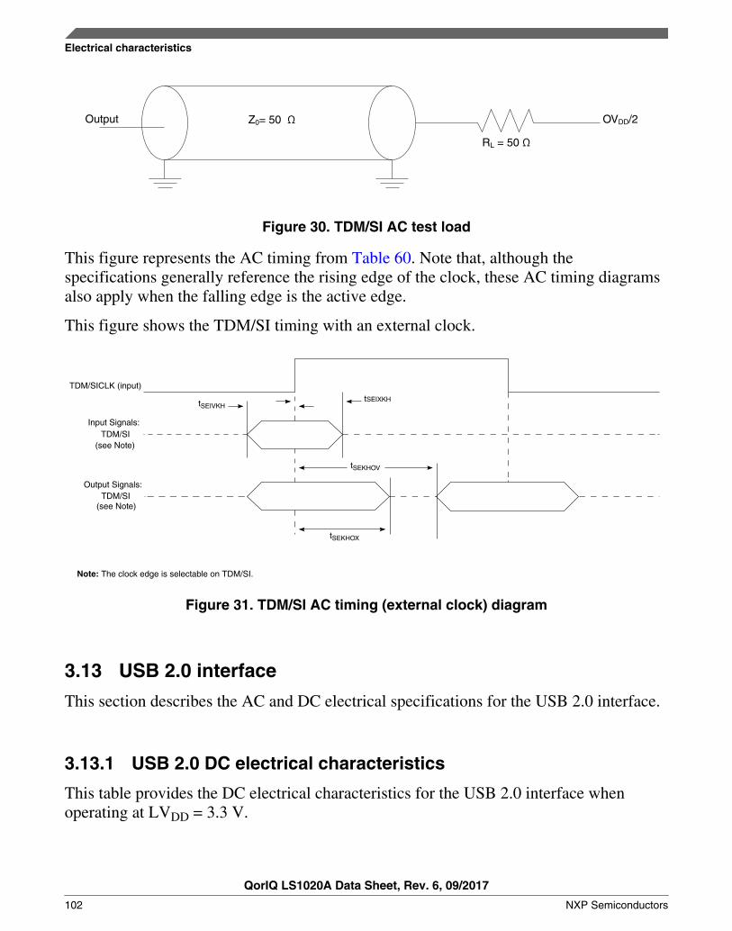
Output Z0= 50 Ω
RL = 50 Ω
OVDD/2
Figure 30. TDM/SI AC test load
This figure represents the AC timing from Table 60. Note that, although thespecifications generally reference the rising edge of the clock, these AC timing diagramsalso apply when the falling edge is the active edge.
This figure shows the TDM/SI timing with an external clock.
TDM/SICLK (input)
Input Signals:
(see Note)
Output Signals:
(see Note)
Note: The clock edge is selectable on TDM/SI.
tSEIVKHtSEIXKH
tSEKHOV
tSEKHOX
TDM/SI
TDM/SI
Figure 31. TDM/SI AC timing (external clock) diagram
3.13 USB 2.0 interface
This section describes the AC and DC electrical specifications for the USB 2.0 interface.
3.13.1 USB 2.0 DC electrical characteristics
This table provides the DC electrical characteristics for the USB 2.0 interface whenoperating at LVDD = 3.3 V.
Electrical characteristics
QorIQ LS1020A Data Sheet, Rev. 6, 09/2017
102 NXP Semiconductors

Table 61. USB 2.0 DC electrical characteristics (3.3 V)3
Parameter Symbol Min Max Unit Notes
Input high voltage VIH 0.7 x LVDD — V 1
Input low voltage VIL — 0.2 x LVDD V 1
Input current (VIN = 0 V or VIN= LVDD) IIN — ±50 μA 2
Output high voltage
(LVDD = min, IOH = -2 mA)
VOH 2.4 — V —
Output low voltage
(LVDD = min, IOL = 2 mA)
VOL — 0.4 V —
Notes:
1. The min VILand max VIH values are based on the respective min and max LVIN values found in Table 3.
2. The symbol VIN, in this case, represents the LVIN symbol referenced in Table 3.
3. For recommended operating conditions, see Table 3.
This table provides the DC electrical characteristics for the USB 2.0 interface whenoperating at LVDD = 2.5 V.
Table 62. USB 2.0 DC electrical characteristics (2.5 V)3
Parameter Symbol Min Max Unit Notes
Input high voltage VIH 0.7 x LVDD — V 1
Input low voltage VIL — 0.2 x LVDD V 1
Input current (VIN = 0 V or VIN= LVDD/L1VDD)
IIN — ±50 μA 2
Output high voltage
(LVDD/L1VDD = min, IOH = -1 mA)
VOH 2.0 — V —
Output low voltage
(LVDD/L1VDD = min, IOL = 1 mA)
VOL — 0.4 V —
Notes:
1. The min VILand max VIH values are based on the respective min and max LVIN/L1VIN values found in Table 3.
2. The symbol VIN, in this case, represents the LVIN/L1VIN symbol referenced in Table 3.
3. For recommended operating conditions, see Table 3.
This table provides the DC electrical characteristics for the USB 2.0 interface whenoperating at LVDD = 1.8 V.
Table 63. USB 2.0 DC electrical characteristics (1.8 V)3
Parameter Symbol Min Max Unit Notes
Input high voltage VIH 0.7 x LVDD — V 1
Input low voltage VIL — 0.2 x LVDD V 1
Input current (VIN = 0 V or VIN = LVDD) IIN — ±50 μA 2
Table continues on the next page...
Electrical characteristics
QorIQ LS1020A Data Sheet, Rev. 6, 09/2017
NXP Semiconductors 103

Table 63. USB 2.0 DC electrical characteristics (1.8 V)3 (continued)
Parameter Symbol Min Max Unit Notes
Output high voltage
(LVDD = min, IOH = -0.5 mA)
VOH 1.35 — V —
Output low voltage
(LVDD = min, IOL = 0.5 mA)
VOL — 0.4 V —
Notes:
1. The min VILand max VIH values are based on the respective min and max LVIN values found in Table 3.
2. The symbol VIN, in this case, represents the LVIN symbol referenced in Table 3.
3. For recommended operating conditions, see Table 3.
3.13.2 USB 2.0 AC timing specifications
3.13.2.1 USB 2.0 AC timing specifications for ULPI mode
This table provides the general timing parameters of the USB 2.0 interface for ULPImode.
Table 64. USB 2.0 general timing parameters (ULPI mode only)1, 6, 7
Parameter Symbol1,
6
Min Max Unit Notes
USB clock cycle time tUSCK 15 — ns 2, 3, 4, 5
Input setup to USB clock--all inputs tUSIVKH 4 — ns 2, 3, 4, 5
Input hold to USB clock--all inputs tUSIXKH 1 — ns 2, 3, 4, 5
USB clock to output valid--all outputs tUSKHOV — 7 ns 2, 3, 4, 5
Output hold from USB clock--all outputs tUSKHOX 2 — ns 2, 3, 4, 5
Notes:
1. The symbols for timing specifications follow these patterns: t(First two letters of functional block)(signal)(state)(reference)(state) for inputsand t(First two letters of functional block)(reference)(state)(signal)(state) for outputs. For example, tUSIXKH symbolizes USB timing (US) for theinput (I) to go invalid (X) with respect ot the time the USB clock reference (K) goes high (H). Also, tUSKHOX symbolizes USBtiming (US) for the USB clock reference (K) to go high (H) with respect to the output (O) going invalid (X) or output hold time.
2. All timings are in reference to the USB 2.0 clock.
3. All signals are measured from OVDD/2 of the rising edge of the USB 2.0 clock to 0.4 x OVDD of the signal in question for3.3 V signaling levels.
4. Input timings are measured at the pin.
5. For active/float timing measurements, the high impedance or off state is defined to be when the total current deliveredthrough the component pin is less than or equal to that of the leakage current specification.
6.When switching the data pins from outputs to inputs using the USBn_DIR pin, the output timings will be violated on thatcycle because the output buffers are tristated asynchronously. This should not be a problem, because the PHY should not befunctionally looking at these signals on that cycle as per ULPI specifications.
7. For recommended operating conditions, see Table 3.
Electrical characteristics
QorIQ LS1020A Data Sheet, Rev. 6, 09/2017
104 NXP Semiconductors

This figure provides the AC test load for the USB 2.0.
Output Z0= 50 Ω
RL = 50 Ω
(L/O) VDD/2
Figure 32. USB 2.0 AC test load
This figure provides the AC signals for the USB 2.0 interface for ULPI mode.
USB0_CLK/USB1_CLK/DR_CLK
Inpu t S igna ls
O u tpu t S ign a ls
tUSKHOV tUSKHOX
tUSIVKH
tUSIXKH
Figure 33. USB 2.0 ULPI mode AC Signals
This table provides the USB 2.0 clock input (USB_CLK_IN) AC timing specifications.
Table 65. USB_CLK_IN AC timingspecifications
Parameter Condition Symbol Min Typ Max Unit
Frequency range Steady state fUSB_CLK_IN 59.97 60 60.03 MHz
Clock frequency tolerance — tCLK_TOL - 0.05 0 0.05 %
Reference clock duty cycle Measured at risingedge and/or fallingedge at LVDD/2
tCLK_DUTY 40 50 60 %
Total input jitter time interval error Peak-to-peak valuemeasured with asecond-order, high-pass filter of 500-kHzbandwidth
tCLK_PJ — — 200 ps
Electrical characteristics
QorIQ LS1020A Data Sheet, Rev. 6, 09/2017
NXP Semiconductors 105

3.14 USB 3.0 interface
This section describes the DC and AC electrical specifications for the USB 3.0 interface.
3.14.1 USB 3.0 PHY transceiver supply DC voltage
This table provides the DC electrical characteristics for the USB 3.0 interface whenoperating at USB_HVDD = 3.3 V.
Table 66. USB 3.0 PHY transceiver supply DC voltage (USB_HVDD = 3.3 V)2
Parameter Symbol Min Max Unit Notes
Input high voltage VIH 2.0 — V 1
Input low voltage VIL — 0.8 V 1
Output high voltage (USB_HVDD = min, IOH = -2 mA) VOH 2.8 — V —
Output low voltage (USB_HVDD = min, IOL = 2 mA) VOL — 0.3 V —
Notes:
1. The min VILand max VIH values are based on the respective min and max USB_HVIN values found in Table 3.
2. For recommended operating conditions, see Table 3.
3.14.2 USB 3.0 DC electrical characteristics
This table provides the USB 3.0 transmitter DC electrical characteristics at package pins.
Table 67. USB 3.0 transmitter DC electrical characteristics1
Characteristic Symbol Min Nom Max Unit
Differential output voltage Vtx-diff-pp 800 1000 1200 mVp-p
Low power differential output voltage Vtx-diff-pp-low 400 — 1200 mVp-p
Tx de-emphasis Vtx-de-ratio 3 — 4 dB
Differential impedance ZdiffTX 72 100 120 Ohm
Tx common mode impedance RTX-DC 18 — 30 Ohm
Absolute DC common mode voltage between U1 and U0 TTX-CM-DC-
ACTIVEIDLE-
DELTA
— — 200 mV
DC electrical idle differential output voltage VTX-IDLE-
DIFF-DC
0 — 10 mV
Note:
1. For recommended operating conditions, see Table 3.
This table provides the USB 3.0 receiver DC electrical characteristics at the Rx packagepins.
Electrical characteristics
QorIQ LS1020A Data Sheet, Rev. 6, 09/2017
106 NXP Semiconductors

Table 68. USB 3.0 receiver DC electrical characteristics
Characteristic Symbol Min Nom Max Unit Notes
Differential Rx input impedance RRX-DIFF-DC 72 100 120 Ohm —
Receiver DC common mode impedance RRX-DC 18 — 30 Ohm —
DC input CM input impedance for V > 0 duringreset or power down
ZRX-HIGH-IMP-DC
25 K — — Ohm —
LFPS detect threshold VRX-IDLE-DET-DC-DIFFpp
100 — 300 mV 1
Note:
1. Below the minimum is noise. Must wake up above the maximum.
3.14.3 USB 3.0 AC timing specifications
This table provides the USB 3.0 transmitter AC timing specifications at package pins.
Table 69. USB 3.0 transmitter AC timing specifications1
Parameter Symbol Min Nom Max Unit Notes
Speed — — 5.0 — Gb/s —
Transmitter eye tTX-Eye 0.625 — — UI —
Unit interval UI 199.94 — 200.06 ps 2
AC coupling capacitor ACcouplingcapacitor
75 — 200 nF —
Note:
1. For recommended operating conditions, see Table 3.
2. UI does not account for SSC-caused variations.
This table provides the USB 3.0 receiver AC timing specifications at Rx package pins.
Table 70. USB 3.0 receiver AC timing specifications1
Parameter Symbol Min Nom Max Unit Notes
Unit interval UI 199.94 — 200.06 ps 2
Notes:
1. For recommended operating conditions, see Table 3.
2. UI does not account for SSC-caused variations.
Electrical characteristics
QorIQ LS1020A Data Sheet, Rev. 6, 09/2017
NXP Semiconductors 107

3.14.4 USB 3.0 reference clock requirements
This table summarizes the requirements of the reference clock provided to the USB 3.0SSPHY. There are two options for the reference clock of USB PHY: SYSCLK orDIFF_SYSCLK/DIFF_SYSCLK_B. The following table provides the additionalrequirements when SYSCLK or DIFF_SYSCLK/DIFF_SYSCLK_B is used as USBREFCLK. This table can also be used for 100 MHz reference clock requirements.
Table 71. Reference clock requirements
Parameter Symbol Min Typ Max Unit Notes
Reference clock frequency offset FREF_OFFSET -300 — 300 ppm —
Reference clock random jitter (RMS) RMSJREF_CLK — — 3 ps 1, 2
Reference clock deterministic jitter DJREF_CLK — — 150 ps 3
Duty cycle DCREF_CLK 40 — 60 % —
Notes:
1. 1.5 MHz to Nyquist frequency. For example, for 100 MHz reference clock, the Nyquist frequency is 50 MHz.
2. The peak-to-peak Rj specification is calculated as 14.069 times the RMS Rj for 10-12 BER.
3. DJ across all frequencies.
3.14.5 USB 3.0 LFPS specifications
This table provides the key LFPS electrical specifications at the transmitter.
Table 72. LFPS electrical specifications at the transmitter
Parameter Symbol Min Typ Max Unit Notes
Period tPeriod 20 — 100 ns —
Peak-to-peak differential amplitude VTX-DIFF-PP-LFPS 800 — 1200 mV —
Low-power peak-to-peak differentialamplitude
VTX-DIFF-PP-LFPS-LP 400 — 600 mV —
Rise/fall time tRiseFall2080 — — 4 ns 1
Duty cycle Duty cycle 40 — 60 % 1
Note:
1. Measured at compliance TP1. See Figure 34 for details.
This figure shows the Tx normative setup with reference channel as per USB 3.0specifications.
Electrical characteristics
QorIQ LS1020A Data Sheet, Rev. 6, 09/2017
108 NXP Semiconductors

Measurement Tool Reference Test Channel Reference Cable DUTSMP
TP1
Figure 34. Tx normative setup
3.15 Integrated flash controller (IFC)
This section describes the DC and AC electrical specifications for the integrated flashcontroller (IFC).
3.15.1 IFC DC electrical characteristics
This table provides the DC electrical characteristics for the IFC when operating atBVDD= 3.3 V.
Table 73. IFC DC electrical characteristics (3.3 V)3
Parameter Symbol Min Max Unit Notes
Input high voltage VIH 0.7 x BVDD — V 1
Input low voltage VIL — 0.2 x BVDD V 1
Input current (VIN = 0 V or VIN= BVDD) IIN — ±50 μA 2
Output high voltage
(BVDD = min, IOH = -2 mA)
VOH 2.4 — V —
Output low voltage
(BVDD = min, IOL = 2 mA)
VOL — 0.4 V —
Notes:
1. The min VILand max VIH values are based on the respective min and max BVIN values found in Table 3.
2. The symbol VIN, in this case, represents the BVIN symbol referenced in Table 3.
3. For recommended operating conditions, see Table 3.
This table provides the DC electrical characteristics for the IFC when operating at BVDD= 1.8 V.
Table 74. IFC DC electrical characteristics (1.8 V)3
Parameter Symbol Min Max Unit Note
Input high voltage VIH 0.7 x BVDD — V 1
Input low voltage VIL — 0.2 x BVDD V 1
Table continues on the next page...
Electrical characteristics
QorIQ LS1020A Data Sheet, Rev. 6, 09/2017
NXP Semiconductors 109

Table 74. IFC DC electrical characteristics (1.8 V)3 (continued)
Parameter Symbol Min Max Unit Note
Input current
(VIN = 0 V or VIN = BVDD)
IIN — ±50 µA 2
Output high voltage
(BVDD = min, IOH = -0.5 mA)
VOH 1.35 — V —
Output low voltage
(BVDD = min, IOL = 0.5 mA)
VOL — 0.4 V —
Notes:
1. The min VILand max VIH values are based on the respective min and max BVIN values found in Table 3.
2. The symbol VIN, in this case, represents the BVIN symbol referenced in Table 3.
3. For recommended operating conditions, see Table 3.
3.15.2 IFC AC timing specifications
This section describes the AC timing specifications for the IFC.
3.15.2.1 Test condition
This figure shows the AC test load for the IFC.
Output Z0= 50 Ω
RL = 50 Ω
OVDD/2
Figure 35. IFC AC test load
3.15.2.2 IFC input AC timing specifications
This table provides the input AC timing specifications of the IFC-GPCM and IFC-GASIC interfaces.
Table 75. IFC input timing specifications for GPCM and GASIC mode (BVDD = 1.8/3.3 V)
Parameter Symbol Min Max Unit Notes
Input setup tIBIVKH1 4 — ns —
Table continues on the next page...
Electrical characteristics
QorIQ LS1020A Data Sheet, Rev. 6, 09/2017
110 NXP Semiconductors

Table 75. IFC input timing specifications for GPCM and GASIC mode (BVDD = 1.8/3.3 V)(continued)
Parameter Symbol Min Max Unit Notes
Input hold tIBIXKH1 1 — ns —
This figure shows the input AC timing diagram for the IFC-GPCM and IFC-GASICinterfaces.
IFC_CLK[0]
Input Signals
t IBIVKH 1
tIBIXKH1
Figure 36. IFC-GPCM and IFC-GASIC input AC timings
This table provides the input timing specifications of the IFC-NOR interface.
Table 76. IFC input timing specifications for NOR mode (BVDD = 1.8/3.3 V)2
Parameter Symbol Min Max Unit Notes
Input setup tIBIVKH2 (2 x tIP_CLK) + 2 — ns 1
Input hold tIBIXKH2 1 x tIP_CLK — ns 1
Notes:
1. tIP_CLK is the period of ip clock (not the IFC_CLK) on which IFC is running.
2. For recommended operating conditions, see Table 3.
This figure shows the AC input timing diagram for input signals of the IFC-NORinterface. Here, TRAD is a programmable delay parameter. Refer to the IFC section ofLS1020A QorIQ Advanced Multicore Processor Reference Manual for more information.
Electrical characteristics
QorIQ LS1020A Data Sheet, Rev. 6, 09/2017
NXP Semiconductors 111

OE_B
AD (Data Phase, Read)
(TRAD+1) x tIP_CLK
tIBIVKH2tIBIXKH2
Note: IP_CLK is the internal clock on which IFC is running. It is not available on interface pins.
Figure 37. IFC-NOR interface input AC timings
This table provides the input timing specifications of the IFC-NAND interface.
Table 77. IFC input timing specifications for NAND mode (BVDD = 1.8/3.3 V)2
Parameter Symbol Min Max Unit Notes
Input setup tIBIVKH3 (2 x tIP_CLK) + 2 — ns 1
Input hold tIBIXKH3 1 x tIP_CLK — ns 1
IFC_RB_B pulse width tIBCH 2 — tIP_CLK 1
Notes:
1. tIP_CLK is the period of ip clock on which IFC is running.
2. For recommended operating conditions, see Table 3.
This figure shows the AC input timing diagram for input signals of the IFC-NANDinterface. Here, TRAD is a programmable delay parameter. Refer to the IFC section ofLS1020A QorIQ Advanced Multicore Processor Reference Manual for more information.
I/O [0:5]
OE_B (TRAD +1 ) x tIP_CLK
tIBIVKH3IBIVKH3t
Note: tIP_CLK is the period of IP clock (not the IFC_CLK) on which IFC is running.
Figure 38. IFC-NAND interface input AC timings
Electrical characteristics
QorIQ LS1020A Data Sheet, Rev. 6, 09/2017
112 NXP Semiconductors

3.15.2.3 IFC output AC timing specifications
This table provides the output AC timing specifications of the IFC-GPCM and IFC-GASIC interface.
Table 78. IFC-GPCM and IFC-GASIC interface output timing specifications (BVDD = 1.8/3.3V)2
Parameter Symbol Min Max Unit Notes
IFC_CLK cycle time tIBK 10 — ns —
IFC_CLK duty cycle tIBKH/ tIBK 45 55 % —
Output delay tIBKLOV1 — 1.5 ns —
Output hold tIBKLOX — -2 ns 1
IFC_CLK[0] to IFC_CLK[m] skew tIBKSKEW 0 ±150 ps —
Notes:
1. Output hold is negative. This means that output transition happens earlier than the falling edge of IFC_CLK.
2. For recommended operating conditions, see Table 3.
This figure shows the output AC timing diagram for the IFC-GPCM and IFC-GASICinterfaces.
Output Signals
IFC_CLK_0
tIBKLOX t
IBKLOX
Figure 39. IFC-GPCM and IFC-GASIC signals
This table provides the output AC timing specifications of the IFC-NOR interface.
Table 79. IFC-NOR interface output timing specifications (BVDD = 1.8/3.3 V)
Parameter Symbol Min Max Unit Notes
Output delay tIBKLOV2 — +/-1.5 ns 1
Notes:
Electrical characteristics
QorIQ LS1020A Data Sheet, Rev. 6, 09/2017
NXP Semiconductors 113

Table 79. IFC-NOR interface output timing specifications (BVDD = 1.8/3.3 V)
Parameter Symbol Min Max Unit Notes
1. This effectively means that a signal change may appear anywhere within ±tIBKLOV2 (max) duration, from the point where itis expected to change.
2. For recommended operating conditions, see Table 3.
This figure shows the AC timing diagram for output signals of the IFC-NOR interface.
The timing specifications have been illustrated here by taking timings between twosignals, CS_B and OE_B, as an example. OE_B is intended to change TACO (aprogrammable delay) time after CS_B. Refer to the IFC section of LS1020A QorIQAdvanced Multicore Processor Reference Manual for more information.
Because of skew between the signals, OE_B may change anywhere within the timewindow tIBKLOV2 (min) and tIBKLOV2 (max). This concept applies to other output signalsof the IFC-NOR interface, as well.
CS_B
OE_B
TACOIBKLOV2t
Figure 40. IFC-NOR Interface output AC timings
This table provides the output AC timing specifications of the IFC-NAND interface.
Table 80. IFC-NAND interface output timing specifications (BVDD = 1.8/3.3 V)2
Parameter Symbol Min Max Unit Notes
Output delay tIBKLOV3 — +/-1.5 ns 1
Notes:
1. This effectively means that a signal change may appear anywhere within tIBKLOV3 (min) to tIBKLOV3 (max) duration, from thepoint where it is expected to change.
2. For recommended operating conditions, see Table 3.
This figure shows the AC timing diagram for output signals of the IFC-NAND interface.
The timing specifications have been illustrated here by taking timings between twosignals, CS_B and CLE, as an example. CLE is intended to change TCCST (aprogrammable delay) time after CS_B. Refer to the IFC section of LS1020A QorIQAdvanced Multicore Processor Reference Manual for more information.
Electrical characteristics
QorIQ LS1020A Data Sheet, Rev. 6, 09/2017
114 NXP Semiconductors

Because of skew between the signals, CLE may change anywhere within the timewindow tIBKLOV3 (min) and tIBKLOV3 (max). This concept applies to other output signalsof the IFC-NAND interface, as well.
CS_B
CLE
TCCST tIBKLOV3
Figure 41. IFC-NAND interface output AC timings
3.15.3 IFC NAND Source Synchronous interface AC timingspecifications
This table describes the AC timing specifications of the IFC-NAND Source Synchronousinterface.
Table 81. IFC-NAND Source Synchronous interface AC timing specifications (BVDD = 1.8/3.3V)4
Parameter Symbol I/O Min Max Unit Notes
Command/address DQ hold time tCAH O 2.5 — ns —
CLE and ALE hold time tCALH O 2.5 — ns —
CLE and ALE setup time tCALS O 2.5 — ns —
Command/address DQ setup time tCAS O 2.5 — ns —
CE# hold time tCH O 2.5 — ns —
Data DQ setup time tDS O 1 — ns —
Data DQ hold time tDH O 1 — ns —
Average clock cycle time (reference signal pinname IFC_NDDDR_CLK)
tCK(avg) ortCK
O 13.33 — ns 1
Absolute clock period tCK(abs) O tCK(avg)-0.5
tCK(avg)+0.5
ns —
Clock cycle high tCKH(abs) O 0.44 0.56 tCK 2
Clock cycle low tCKL(abs) O 0.44 0.56 tCK —
DQS output high pulse width tDQSH O 0.43 0.57 tCK 3
DQS output low pulse width tDQSL O 0.43 0.57 tCK 3
DQS-DQ skew, DQS to last DQ valid, per access tDQSQ I — 1ns=1.8V
570ps=3.3V
— 5
Table continues on the next page...
Electrical characteristics
QorIQ LS1020A Data Sheet, Rev. 6, 09/2017
NXP Semiconductors 115

Table 81. IFC-NAND Source Synchronous interface AC timing specifications (BVDD = 1.8/3.3V)4 (continued)
Parameter Symbol I/O Min Max Unit Notes
Data output to first DQS latching transition tDQSS O (0.75 * tCK)+150ps
(1.25 *tCK) -150ps
tCK —
DQS cycle time tDSC O 10 — ns —
DQS falling edge to CLK rising – hold time tDSH O (0.2 * tck) +150ps
— tCK —
DQS falling edge to CLK rising – setup time tDSS O 0.3 — tCK —
Input data valid window tDVW I 2.1ns=1.8V
2.95ns=3.3V
— ns 5
Half-clock period tHP O 4.4 — ns —
The deviation of a given tCK(abs) from tCK(avg) tJIT(per) O -0.5 0.5 ns —
DQ-DQS hold, DQS to first DQ to go non-valid,per access
tQH I 4.64 — ns —
Notes:
1. tCK(avg) is the average clock period over any consecutive 200 cycle window.
2. tCKH(abs) and tCKL(abs) include static off set and duty cycle jitter.
3. tDQSL and tDQSH are relative to tCK when CLK is running . If CLK is stopped during data input, then tDQSL and tDQSH arerelative to tDSC.
4. For recommended operating conditions, see Table 3
5. These AC parameters do not meet ONFI standard. The board designer needs to take into account trace length for thesesignals to meet the timing requirement.
These figures show the AC timing diagram for IFC-NAND source synchronous interface.
Electrical characteristics
QorIQ LS1020A Data Sheet, Rev. 6, 09/2017
116 NXP Semiconductors

CE_B
CLE
ALE
CLK
W/R_B
DQS
DQ[7:0]
tCALS
tCALS
tCALS tCALH
tCKL tCKH
tCK
tCALS
tDQSHZ
tCALH
tCAS tCAH
tCH
Command
Figure 42. Command cycle
CE#
CLE
ALE
CLK
W/R#
DQS
DQ[7:0]
tCALS
tCALS
tCALS tCALH
tCKL tCKH
tCK
tCALS
tDQSHZ
tCALH
tCAS tCAH
tCH
Address
Figure 43. Address cycle
Electrical characteristics
QorIQ LS1020A Data Sheet, Rev. 6, 09/2017
NXP Semiconductors 117

CE#
CLE
ALE
CLK
W/R#
DQS
DQ[7:0]
tCKL tCKH
tCK
tCAD
tCALS
tCALS
tCALH
tCALH
tCH
tDQSS tDSH tDSS tDSH
tDQSHtDQSL tDQSH tDQSL tDQSH
tDSStDSH tDSStDSH
tDHtDS
tDH
D0 D1tDS
DN-2D3D2 DN-1 DN
Figure 44. Write cycle
CE_B
CLE
ALE
CLK
W/R_B
DQS
DQ[7:0]
tCALS
tCALS tCALH
tCALHtCALS
tHPtHP
tDSC
tDQSD
tCKH tCKL
tDVW tDVW tDVW
tCALS tDQSHZ
tDQSQ
Don't Care
tCK
tHPtHP
tHPtHP
tDQSQtQH tQH tQH tQH
tDQSQ tDQSQ
Data Transitioning Device Driving
tCH
D1D0
tDVW tDVW
D2 D3 D0 D0 D0 D0
Figure 45. Read cycle
3.16 LPUART interface
This section describes the DC and AC electrical specifications for the LPUART interface.
Electrical characteristics
QorIQ LS1020A Data Sheet, Rev. 6, 09/2017
118 NXP Semiconductors

3.16.1 LPUART DC electrical characteristics
This table provides the DC electrical characteristics for the LPUART interface whenoperating at DVDD = 3.3 V.
Table 82. LPUART DC electrical characteristics (3.3 V)2
Parameter Symbol Min Max Unit Notes
Input high voltage VIH 0.7 x DVDD — V 1
Input low voltage VIL — 0.2 xDVDD
V 1
Input current (DVIN = 0 V or DVIN = DVDD) IIN — ±50 μA —
Output high voltage ( IOH = -2.0 mA) VOH 2.4 — V —
Output low voltage ( IOL = 2.0 mA) VOL — 0.4 V —
Notes:
1. The min VILand max VIH values are based on the min and max DVDD respective values found in Table 3.
2. For recommended operating conditions, see Table 3.
This table provides the DC electrical characteristics for the LPUART interface whenoperating at DVDD = 1.8 V.
Table 83. LPUART DC electrical characteristics (1.8 V)3
Parameter Symbol Min Max Unit Notes
Input high voltage VIH 0.7 x DVDD — V 1
Input low voltage VIL — 0.2 xDVDD
V 1
Input current (DVIN = 0 V or DVIN = DVDD) IIN — ±50 μA 2
Output high voltage (DVDD = min, IOH = -0.5 mA) VOH 1.35 — V —
Output low voltage (DVDD = min, IOL = 0.5 mA) VOL — 0.4 V —
Notes:
1. The min VILand max VIH values are based on the min and max DVDD respective values found in Table 3.
2. The symbol DVIN represents the input voltage of the supply referenced in Table 3.
3. For recommended operating conditions, see Table 3.
3.16.2 LPUART AC timing specifications
This table provides the AC timing specifications for the LPUART interface.
Table 84. LPUART AC timing specifications
Parameter Value Unit Notes
Minimum baud rate fPLAT/(2 x 32 x 8192) baud 1, 3, 4
Table continues on the next page...
Electrical characteristics
QorIQ LS1020A Data Sheet, Rev. 6, 09/2017
NXP Semiconductors 119

Table 84. LPUART AC timing specifications(continued)
Parameter Value Unit Notes
Maximum baud rate fPLAT/(2 x 4) baud 1, 2, 4
Notes:
1. fPLAT refers to the internal platform clock.
2. The actual attainable baud rate is limited by the latency of interrupt processing.
3. Every bit can be over sampled with a sample clock rate of 8 and 64 times (software configurable) and each bit is themajority of the values sampled at the sample rate divided by two, (sample rate/2)+1 and (sample rate/2)+2.
4. The 1-to-0 transition during a data word can cause a resynchronization of the sample point.
3.17 Flextimer interface
This section describes the DC and AC electrical characteristics for the Flextimerinterface. There are Flextimer pins on various power supplies in this device.
3.17.1 Flextimer DC electrical characteristics
This table provides the DC electrical characteristics for Flextimer pins operating atL/L1/D/BVDD = 3.3 V.
Table 85. Flextimer DC electrical characteristics (3.3 V)3
Parameter Symbol Min Max Unit Notes
Input high voltage VIH 0.7 x nVDD — V 1
Input low voltage VIL — 0.2 x nVDD V 1
Input current (VIN = 0 V or VIN= L/L1/D/BVDD)
IIN — ±50 μA 2
Output high voltage
(L/L1/D/BVDD = min, IOH = -2 mA)
VOH 2.4 — V —
Output low voltage
(L/L1/D/BVDD = min, IOL = 2 mA)
VOL — 0.4 V —
Notes:
1. The min VILand max VIH values are based on the respective min and max L/L1/D/BVIN values found in Table 3.
2. The symbol VIN, in this case, represents the L/L1/D/BVIN symbol referenced in Table 3.
3. For recommended operating conditions, see Table 3.
This table provides the DC electrical characteristics for Flextimer pins operating atLVDD/L1VDD = 2.5 V.
Electrical characteristics
QorIQ LS1020A Data Sheet, Rev. 6, 09/2017
120 NXP Semiconductors

Table 86. Flextimer DC electrical characteristics (2.5 V)3
Parameter Symbol Min Max Unit Notes
Input high voltage VIH 0.7 x nVDD — V 1
Input low voltage VIL — 0.2 x nVDD V 1
Input current (VIN = 0 V or VIN= LVDD/L1VDD)
IIN — ±50 μA 2
Output high voltage
(LVDD/L1VDD = min, IOH = -1 mA)
VOH 2.0 — V —
Output low voltage
(LVDD/L1VDD = min, IOL = 1 mA)
VOL — 0.4 V —
Notes:
1. The min VILand max VIH values are based on the respective min and max LVIN/L1VIN values found in Table 3.
2. The symbol VIN, in this case, represents the LVIN/L1VIN symbol referenced in Table 3.
3. For recommended operating conditions, see Table 3.
This table provides the DC electrical characteristics for Flextimer pins operating atL/L1/D/BVDD = 1.8 V.
Table 87. Flextimer DC electrical characteristics (1.8 V)3
Parameter Symbol Min Max Unit Notes
Input high voltage VIH 0.7 x nVDD — V 1
Input low voltage VIL — 0.2 x nVDD V 1
Input current (VIN = 0 V or VIN = L/L1/D/BVDD)
IIN — ±50 μA 2
Output high voltage
(L/L1/D/BVDD = min, IOH = -0.5 mA)
VOH 1.35 — V —
Output low voltage
(L/L1/D/BVDD = min, IOL = 0.5 mA)
VOL — 0.4 V —
Notes:
1. The min VILand max VIH values are based on the respective min and max L/L1/D/BVIN values found in Table 3.
2. The symbol VIN, in this case, represents the L/L1/D/BVIN symbol referenced in Table 3.
3. For recommended operating conditions, see Table 3.
3.17.2 Flextimer AC timing specifications
This table provides the Flextimer AC timing specifications.
Electrical characteristics
QorIQ LS1020A Data Sheet, Rev. 6, 09/2017
NXP Semiconductors 121

Table 88. Flextimer AC timing specifications2
Parameter Symbol Min Unit Notes
Flextimer inputs—minimum pulse width tPIWID 20 ns 1
Notes:
1. Flextimer inputs and outputs are asynchronous to any visible clock. Flextimer outputs should be synchronized before useby any external synchronous logic. Flextimer inputs are required to be valid for at least tPIWID to ensure proper operation.
2. For recommended operating conditions, see Table 3.
This figure provides the AC test load for the Flextimer.
Output Z0= 50 Ω
RL = 50 Ω
(L/O) VDD/2
Figure 46. Flextimer AC test load
3.18 SAI/I2S interface
This section describes the DC and AC electrical characteristics for the SAI/I2S interface.There are SAI/I2S pins on various power supplies in this device.
3.18.1 SAI/I2S DC electrical characteristics
This table provides the SAI/I2S DC electrical characteristics when L1VDD/DVDD = 3.3 V.
Table 89. SAI/I2S DC electrical characteristics (L1VDD/DVDD = 3.3 V) 4
Parameter Symbol Min Max Unit Notes
Input high voltage VIH 0.7 x nVDD — V 1
Input low voltage VIL — 0.2 x nVDD V 1
Input current (L1VIN = 0 V or L1VIN = L1VDD) IIN — ±50 µA 2, 3
Output high voltage (L1VDD = min, IOH = -2 mA) VOH 2.4 — V —
Output low voltage (L1VDD = min, IOL = 2 mA) VOL — 0.4 V —
Notes:
1. The min VILand max VIH values are based on the respective min and max L1VIN/DVIN values found in Table 3.
2. The symbol L1VIN, in this case, represents the L1VIN/DVIN symbol referenced in Table 3.
Electrical characteristics
QorIQ LS1020A Data Sheet, Rev. 6, 09/2017
122 NXP Semiconductors

Table 89. SAI/I2S DC electrical characteristics (L1VDD/DVDD = 3.3 V) 4
Parameter Symbol Min Max Unit Notes
3. The symbol L1VDD, in this case, represents the L1VDD/DVDD symbols referenced in Table 3.
4. For recommended operating conditions, see Table 3.
This table provides the SAI/I2S DC electrical characteristics when L1VDD = 2.5 V.
Table 90. SAI/I2S DC electrical characteristics (L1VDD/DVDD = 2.5 V)4
Parameters Symbol Min Max Unit Notes
Input high voltage VIH 0.7 x nVDD — V 1
Input low voltage VIL — 0.2 x nVDD V 1
Input current (L1VIN = 0 or L1VIN = L1VDD/DVDD) IIN — ±50 µA 2, 3
Output high voltage (L1VDD = min, IOH = -1.0 mA) VOH 2.00 — V —
Output low voltage (L1VDD = min, IOL = 1.0 mA) VOL — 0.40 V —
Notes:
1. The min VILand max VIH values are based on the respective min and max L1VIN/DVDD values found in Table 3.
2. The symbol VIN, in this case, represents the L1VIN/DVDD symbols referenced in Table 3.
3. The symbol L1VDD, in this case, represents the L1VDD/DVDD symbols referenced in Table 3.
4. For recommended operating conditions, see Table 3.
This table provides the SAI/I2S DC electrical characteristics when L1VDD/DVDD = 1.8 V.
Table 91. SAI/I2S DC electrical characteristics (L1VDD/DVDD = 1.8 V)4
Parameter Symbol Min Max Unit Notes
Input high voltage VIH 0.7 x nVDD — V 1
Input low voltage VIL — 0.2 x nVDD V 1
Input current (L1VIN = 0 V or L1VIN = L1VDD) IIN — ±50 µA 2, 3
Output high voltage (L1VDD = min, IOH = -0.5 mA) VOH 1.35 — V 3
Output low voltage (L1VDD = min, IOL = 0.5 mA) VOL — 0.4 V 3
Notes:
1. The min VILand max VIH values are based on the min and max L1VIN/DVDD respective values found in Table 3.
2. The symbol L1VIN represents the L1VIN/DVDD symbols referenced in Table 3.
3. The symbol L1VDD, in this case, represents the L1VDD/DVDD symbols referenced in Table 3.
4. For recommended operating conditions, see Table 3.
3.18.2 SAI/I2S AC timing specifications
This section provides the AC timings for the synchronous audio interface (SAI) in master(clocks driven) and slave (clocks input) modes.
Electrical characteristics
QorIQ LS1020A Data Sheet, Rev. 6, 09/2017
NXP Semiconductors 123

This table provides the SAI timing in master mode.
Table 92. Master mode SAI timing
Parameter Symbol Min Max Unit
SAIn_TX_BCLK/SAIn_RX_BCLK cycletime
tSAIC 20 - ns
SAIn_TX_BCLK/SAIn_RX_BCLK pulsewidth high/low
tSAIL/tSAIH 35% 65% BCLK period
SAIn_TX_BCLK to SAIn_TX_SYNCoutput valid
tSAIMFSLOV - 15 ns
SAIn_TX_BCLK to SAIn_TX_SYNCoutput invalid
tSAIMFSLOX 0 - ns
SAIn_TX_BCLK to SAIn_TX_DATA valid tSAIMLDV - 15 ns
SAIn_TX_BCLK to SAIn_TX_DATA invalid tSAIMLDX 0 - ns
SAIn_RX_DATA/SAIn_RX_SYNC inputsetup before SAIn_RX_BCLK
tSAIMVKH 15 - ns
SAIn_RX_DATA/SAIn_RX_SYNC inputhold after SAIn_RX_BCLK
tSAIMXKH 0 - ns
This figure shows the SAI timing in master modes.
tSAIC
tSAIH
tSAIL
tSAIMFSLOV
tSAIMLOV
tSAIMVKH tSAIMXKH
tSAIMLOX
tSAIMFSLOX
tSAIMXKH
SAIn_Tx_BCLK
SAIn_Tx_SYNC
SAIn_Rx_SYNC
SAIn_Tx_DATA
SAIn_Rx_DATA
tSAIMVKH
tSAIMLOV
tSAIMLOX
Figure 47. SAI timing — master modes
This table provides the SAI timing in slave mode.
Table 93. Slave mode SAI timing
Parameter Symbol Min Max Unit
SAIn_TX_BCLK/SAIn_RX_BCLK cycletime (input)
tSAIC 20 - ns
SAIn_TX_BCLK/SAIn_RX_BCLK pulsewidth high/low (input)
tSAIL/tSAIH 35% 65% BCLK period
Table continues on the next page...
Electrical characteristics
QorIQ LS1020A Data Sheet, Rev. 6, 09/2017
124 NXP Semiconductors

Table 93. Slave mode SAI timing (continued)
SAIn_RX_SYNC input setup beforeSAIn_RX_BCLK
tSAISFSVKH 10 - ns
SAIn_RX_SYNC input hold afterSAIn_RX_BCLK
tSAISFSXKH 2.1 - ns
SAIn_TX_BCLK to SAIn_TX_DATA /SAIn_TX_SYNC output valid
tSAISLOV - 20 ns
SAIn_TX_BCLK to SAIn_TX_DATA/SAIn_TX_SYNC output invalid
tSAISLOX 0 - ns
SAIn_RX_DATA setup beforeSAIn_RX_BCLK
tSAISVKH 10 - ns
SAIn_RX_DATA hold afterSAIn_RX_BCLK
tSAISXKH 2.1 - ns
This figure shows the SAI timing in slave modes.
tSAISFSLOV
tSAISFSVKH
tSAISVKH tSAISXKH
tSAISLOX
tSAIC
tSAIH
tSAIL
SAIn_Rx_BCLK
SAIn_Tx_SYNC
SAIn_Rx_SYNC
SAIn_Tx_DATA
SAIn_Rx_DATA
tSAISFSLOV
tSAISFSLOV
tSAISXKH
tSAISFSXKH
tSAISLOX
Figure 48. SAI timing — slave modes
3.19 SPDIF interface
This section describes the DC and AC electrical characteristics for the Sony/PhilipsDigital Interconnent Formal (SPDIF) interface.
3.19.1 SPDIF DC electrical characteristics
This table provides the DC electrical characteristics for the SPDIF interface whenoperating at DVDD = 3.3 V.
Electrical characteristics
QorIQ LS1020A Data Sheet, Rev. 6, 09/2017
NXP Semiconductors 125

Table 94. SPDIF DC electrical characteristics (DVDD = 3.3 V)3
Parameter Symbol Min Max Unit Notes
Input high voltage VIH 0.7 x DVDD — V 1
Input low voltage VIL — 0.2 x DVDD V 1
Input current (VIN = 0 V or VIN = DVDD) IIN — ±50 μA 2
Output high voltage (DVDD = min, IOH = -2 mA) VOH 2.4 — V —
Output low voltage (DVDD = min, IOH = 2 mA) VOL — 0.4 V —
Notes:
1. The min VILand max VIH values are based on the respective min and max DVIN values found in Table 3.
2. The symbol VIN, in this case, represents the input voltage of the supply referenced in Table 3.
3. For recommended operating conditions, see Table 3.
This table provides the DC electrical characteristics for the SPDIF interface whenoperating at DVDD = 1.8 V.
Table 95. SPDIF DC electrical characteristics (DVDD = 1.8 V)3
Parameter Symbol Min Max Unit Notes
Input high voltage VIH 0.7 x DVDD — V 1
Input low voltage VIL — 0.2 x DVDD V 1
Input current (VIN = 0 V or VIN = DVDD) IIN — ±50 μA 2
Output high voltage (DVDD = min, IOH = -0.5 mA) VOH 1.35 — V —
Output low voltage (DVDD = min, IOH = 0.5 mA) VOL — 0.4 V —
Notes:
1. The min VILand max VIH values are based on the respective min and max DVIN values found in Table 3.
2. The symbol VIN, in this case, represents the input voltage of the supply referenced in Table 3.
3. For recommended operating conditions, see Table 3.
3.19.2 SPDIF AC timing specifications
This table provides the AC timing specifications for the SPDIF interface.
Table 96. SPDIF AC timing specifications
Characteristics Symbol Min Max Unit
SPDIF_IN
Skew: Asynchronous inputs, no specifications apply
— — 0.7 ns
SPDIF_OUT output (load = 50 pf) Skew — — 1.5 ns
Transition rising — — 24.2 ns
Transition falling — — 31.3 ns
Table continues on the next page...
Electrical characteristics
QorIQ LS1020A Data Sheet, Rev. 6, 09/2017
126 NXP Semiconductors

Table 96. SPDIF AC timing specifications(continued)
Characteristics Symbol Min Max Unit
SPDIF_SRCLK period srckp 40.0 — ns
SPDIF_SRCLK high period srckph 16.0 — ns
SPDIF_SRCLK low period srckpl 16.0 — ns
SPDIF_EXTCLK period stclkp 40.0 — ns
SPDIF_EXTCLK high period stclkph 16.0 — ns
SPDIF_EXTCLK low period stclkpl 16.0 — ns
This figure shows the timing for SPDIF_SRCLK.
SPDIF_SRCLK(Output)
srckpl
srckp
srckph
VM VM
Figure 49. SPDIF_SRCLK timing
This figure shows the timing for SPDIF_EXTCLK.
SPDIF_EXTCLK(Input)
stclkpl
stclkp
stclkph
VM VM
Figure 50. SPDIF_EXTCLK timing
3.20 SPI interface
This section describes the DC and AC electrical characteristics for the SPI interface.
3.20.1 SPI DC electrical characteristics
This table provides the DC electrical characteristics for the SPI interface operating atBVDD = 3.3 V.
Electrical characteristics
QorIQ LS1020A Data Sheet, Rev. 6, 09/2017
NXP Semiconductors 127

Table 97. SPI DC electrical characteristics (3.3 V)3
Parameter Symbol Min Max Unit Notes
Input high voltage VIH 0.7 x BVDD — V 1
Input low voltage VIL — 0.2 x BVDD V 1
Input current (VIN = 0 V or VIN= BVDD) IIN — ±50 μA 2
Output high voltage
(BVDD = min, IOH = -2 mA)
VOH 2.4 — V —
Output low voltage
(BVDD = min, IOL = 2 mA)
VOL — 0.4 V —
Notes:
1. The min VILand max VIH values are based on the respective min and max BVIN values found in Table 3.
2. The symbol VIN, in this case, represents the BVIN symbol referenced in Table 3.
3. For recommended operating conditions, see Table 3.
This table provides the DC electrical characteristics for the SPI interface operating atBVDD = 1.8 V.
Table 98. SPI DC electrical characteristics (1.8 V)3
Parameter Symbol Min Max Unit Notes
Input high voltage VIH 0.7 x BVDD — V 1
Input low voltage VIL — 0.2 x BVDD V 1
Input current (VIN = 0 V or VIN = BVDD) IIN — ±50 μA 2
Output high voltage
(BVDD = min, IOH = -0.5 mA)
VOH 1.35 — V —
Output low voltage
(BVDD = min, IOL = 0.5 mA)
VOL — 0.4 V —
Notes:
1. The min VILand max VIH values are based on the respective min and max BVIN values found in Table 3.
2. The symbol VIN, in this case, represents the BVIN symbol referenced in Table 3.
3. For recommended operating conditions, see Table 3.
3.20.2 SPI AC timing specifications
This table provides the SPI timing specifications.
Table 99. SPI AC timing specifications
Parameter Symbol Condition Min Max Unit
SCK Cycle Time tSCK — TPlat*8 — ns
Table continues on the next page...
Electrical characteristics
QorIQ LS1020A Data Sheet, Rev. 6, 09/2017
128 NXP Semiconductors

Table 99. SPI AC timing specifications(continued)
Parameter Symbol Condition Min Max Unit
SCK Clock Pulse Width tSDC — 40% 60% tSCK
CS to SCK Delay tCSC Master 16 — ns
After SCK Delay tASC Master 16 — ns
Slave Access Time (SS active to SOUT driven) tA Slave — 15 ns
Slave Disable Time (SS inactive to SOUT High-Z or invalid) tDI Slave — 10 ns
Data Setup Time for Inputs tNIIVKH Master 8 — ns
tNEIVKH Slave 4 —
Data Hold Time for Inputs tNIIXKH Master 0 — ns
tNEIXKH Slave 2 —
Data Valid (after SCK edge) for Outputs tNIKHOV Master — 5 ns
tNEKHOV Slave — 10
Data Hold Time for Outputs tNIKHOX Master 0 — ns
tNEKHOX Slave 0 —
This figure shows the SPI timing master when CPHA = 0.
Electrical characteristics
QorIQ LS1020A Data Sheet, Rev. 6, 09/2017
NXP Semiconductors 129

SCK Output(CPOL = 0)
SCK Output(CPOL = 1)
CSx
tCSC tASC
tSDC tSCK
tSDC
tNIIVKH
tNIIXKH
tNIKHOX tNIKHOV
SIN
SOUT
First Data Data Last Data
First Data Data Last Data
Figure 51. SPI timing master, CPHA = 0
This figure shows the SPI timing master when CPHA = 1.
Electrical characteristics
QorIQ LS1020A Data Sheet, Rev. 6, 09/2017
130 NXP Semiconductors

SCK Output(CPOL = 0)
SCK Output(CPOL = 1)
CSx
tNIIVKH
t NIKHOX tNIKHOV
SIN
SOUT
First Data Data Last Data
First Data Data Last Data
tNIIXKH
Figure 52. SPI timing master, CPHA = 1
This figure shows the SPI timing slave when CPHA = 0.
Electrical characteristics
QorIQ LS1020A Data Sheet, Rev. 6, 09/2017
NXP Semiconductors 131

SCK Input(CPOL = 0)
SCK Input(CPOL = 1)
SS
t CSC
tASC
tSDC
tSCK
tSDC
tNEIVKHtNEIXKH
tNEKHOX
tNEKHOV
SOUT
SIN
First Data Data Last Data
First Data Data Last Data
tA tDI
Figure 53. SPI timing slave, CPHA = 0
This figure shows the SPI timing slave when CPHA = 1.
Electrical characteristics
QorIQ LS1020A Data Sheet, Rev. 6, 09/2017
132 NXP Semiconductors

SCK Input(CPOL = 0)
SCK Input(CPOL = 1)
SS
tNEIVKH
t
NEIXKHt
NEKHOX
tNEKHOV
SOUT
SIN
First Data Data Last Data
First Data Data Last Data
tA
t DI
Figure 54. SPI timing slave, CPHA = 1
3.21 QuadSPI interface
This section describes the DC and AC electrical characteristics for the QuadSPI interface.
3.21.1 QuadSPI DC electrical characteristics
This table provides the DC electrical characteristics for the QuadSPI interface operatingat BVDD = 3.3 V.
Table 100. QuadSPI DC electrical characteristics (3.3 V)3
Parameter Symbol Min Max Unit Notes
Input high voltage VIH 0.7 x BVDD — V 1
Input low voltage VIL — 0.2 x BVDD V 1
Input current (VIN = 0 V or VIN= BVDD) IIN — ±50 μA 2
Output high voltage VOH 2.4 — V —
Table continues on the next page...
Electrical characteristics
QorIQ LS1020A Data Sheet, Rev. 6, 09/2017
NXP Semiconductors 133

Table 100. QuadSPI DC electrical characteristics (3.3 V)3 (continued)
Parameter Symbol Min Max Unit Notes
(BVDD = min, IOH = -2 mA)
Output low voltage
(BVDD = min, IOL = 2 mA)
VOL — 0.4 V —
Notes:
1. The min VILand max VIH values are based on the respective min and max BVIN values found in Table 3.
2. The symbol VIN, in this case, represents the BVIN symbol referenced in Table 3.
3. For recommended operating conditions, see Table 3.
This table provides the DC electrical characteristics for the QuadSPI interface operatingat BVDD = 1.8 V.
Table 101. QuadSPI DC electrical characteristics (1.8 V)3
Parameter Symbol Min Max Unit Notes
Input high voltage VIH 0.7 x BVDD — V 1
Input low voltage VIL — 0.2 x BVDD V 1
Input current (VIN = 0 V or VIN = BVDD) IIN — ±50 μA 2
Output high voltage
(BVDD = min, IOH = -0.5 mA)
VOH 1.35 — V —
Output low voltage
(BVDD = min, IOL = 0.5 mA)
VOL — 0.4 V —
Notes:
1. The min VILand max VIH values are based on the respective min and max BVIN values found in Table 3.
2. The symbol VIN, in this case, represents the BVIN symbol referenced in Table 3.
3. For recommended operating conditions, see Table 3.
3.21.2 QuadSPI AC timing specifications
This section describes the QuadSPI timing specifications in SDR mode. All data is basedon a negative edge data launch from the device and a positive edge data capture, asshown in the timing figures in this section.
3.21.2.1 QuadSPI timing SDR mode
This table provides the QuadSPI input and output timing in SDR mode.
Electrical characteristics
QorIQ LS1020A Data Sheet, Rev. 6, 09/2017
134 NXP Semiconductors

Table 102. SDR mode QuadSPI input and output timing
Parameter Symbol Min Max Unit
Clock rise/fall time TRISE/TFALL 1 — ns
CS output hold time tNIKHOX2 -3.4 — ns
CS output delay tNIKHOV2 — 3.5 ns
Setup time for incoming data tNIIVKH 8.6 — ns
Hold time requirement for incoming data tNIIXKH 0.4 — ns
Output data valid tNIKHOV
tNIKLOV
— 4.5 ns
Output data hold tNIKHOX
tNIKLOX
-4.4 — ns
Notes:
1. The input timing is relative to the sampling clock edge which is configurable. Please refer to register QuadSPI_SMPR fromLS102xA Reference Manual for more information.
This figure shows the QuadSPI AC timing in SDR mode.
Freescale Confidential ProprietaryPreliminary—Subject to Change Without Notice
Freescale Internal Use Only
Freescale Semiconductor 3
tNIKHOV
Input Signals:
Output Signals:
tNIKHOX
tNIKHOV2tNIKHOX2
QSPI_CK_A QSPI_CK_B
QSPI_CS_A0 QSPI_CS_A1 QSPI_CS_B0 QSPI_CS_B1
tNIIVKHtNIIXKH
Figure 55. QuadSPI AC timing — SDR mode
3.22 Enhanced secure digital host controller (eSDHC)
This section describes the DC and AC electrical specifications for the eSDHC interface.
Note: This section is preliminary and is subject to further change.
Electrical characteristics
QorIQ LS1020A Data Sheet, Rev. 6, 09/2017
NXP Semiconductors 135

3.22.1 eSDHC DC electrical characteristics
This table provides the DC electrical characteristics for the eSDHC interface operating atD/EVDD = 3.3 V.
Table 103. eSDHC interface DC electrical characteristics3
Characteristic Symbol Condition Min Max Unit Notes
Input high voltage VIH — 0.7 x EVDD — V 1
Input low voltage VIL — — 0.2 x EVDD V 1
Output high voltage VOH IOH = -100 μA at EVDDmin
0.75 x EVDD — V —
Output low voltage VOL IOL = 100 μA at EVDDmin
— 0.125 x EVDD V —
Output high voltage VOH IOH = -100 μA EVDD - 0.2 — V 2
Output low voltage VOL IOL = 2 mA — 0.3 V 2
Input/output leakage current IIN/IOZ — -10 10 μA —
Notes:
1. The min VIL and max VIH values are based on the respective min and max EVIN values found in Table 3.
2. Open-drain mode is for MMC cards only.
3. The eSDHC interface is powered by DVDD and EVDD.
This table provides the DC electrical characteristics for the eSDHC interface operating atD/EVDD = 1.8 V or 3.3 V.
Table 104. eSDHC interface DC electrical characteristics (dual-voltage cards)1, 4
Characteristic Symbol Condition Min Max Unit Notes
Input high voltage VIH — 0.7 x EVDD — V 2
Input low voltage VIL — — 0.25 x EVDD V 2
Output high voltage VOH IOH = -100 μA at EVDDmin
EVDD - 0.2 V — V —
Output low voltage VOL IOL= 100 μA at EVDDmin
— 0.2 V —
Output high voltage VOH IOH = -100 μA EVDD - 0.2 — V 3
Output low voltage VOL IOL = 2 mA — 0.3 V 3
Input/Output leakage current IIN/IOZ — -10 10 μA —
Notes:
1. The eSDHC interface is powered by DVDD and EVDD.
2. The min VIL and VIH values are based on the respective min and max D/EVIN values found in Table 3.
3. Open-drain mode is for MMC cards only.
4. For recommended operating conditions, see Table 3.
Electrical characteristics
QorIQ LS1020A Data Sheet, Rev. 6, 09/2017
136 NXP Semiconductors

3.22.2 eSDHC AC timing specifications
This section provides the AC timing specifications.
This table provides the eSDHC AC timing specifications as defined in Figure 56 andFigure 57 (EVDD/DVDD = 1.8 V or 3.3 V).
Table 105. eSDHC AC timing specifications (high speed/ full speed)6
Parameter Symbol1 Min Max Unit Notes
SDHC_CLK clock frequency SD/SDIO (full-speed/high-speedmode)
fSHSCK 0 25/46.5 MHz 2, 4
MMC full-speed/high-speed mode 20/46.5
SDHC_CLK clock low time (full-speed/high-speed mode) tSHSCLK 10/7 — ns 4
SDHC_CLK clock high time (full-speed/high-speed mode) tSHSSCKH 10/7 — ns 4
SDHC_CLK clock rise and fall times tSHSCKR/
tSHSCKF
— 3 ns 4
Input setup times: SDHC_CMD, SDHC_DATx, to SDHC_CLK tSHIVKH 4.1 — ns 3, 4, 5
Input hold times: SDHC_CMD, SDHC_DATx, to SDHC_CLK tSHIXKH 2.5 — ns 3, 4, 5
Output hold time: SDHC_CLK to SDHC_CMD, SDHC_DATx valid tSHKHOX -3 — ns 3, 4, 5
Output delay time: SDHC_CLK to SDHC_CMD, SDHC_DATx valid tSHKHOV — 3.3 ns 3, 4, 5
Notes:
1. The symbols used for timing specifications follow these patterns: t(first three letters of functional block)(signal)(state) (reference)(state) forinputs and t(first three letters of functional block)(reference)(state)(signal)(state) for outputs. For example, tSHDKHOX symbolizes eSDHC devicetiming (SH) Data (D) Command (C) clock reference (K) going to the high (H) state, with respect to the output (O) reaching theinvalid state (X) or output hold time. Note that, in general, the clock reference symbol is based on five letters representing theclock of a particular function. For rise and fall times, the latter convention is used with the appropriate letter: R (rise) or F (fall).
2. In full-speed mode, the clock frequency value can be 0-25 MHz for an SD/SDIO card and 0-20 MHz for an MMC card. Inhigh-speed mode, the clock frequency value can be 0-50 MHz for an SD/SDIO card and 0-52 MHz for an MMC card.
3. Without voltage translator and SDHC_CLK_SYNC_IN and SDHC_CLK_SYNC_OUT, to satisfy setup timing, one-wayboard-routing delay between host and card, on SDHC_CLK, SDHC_CMD, and SDHC_DATx should not exceed 1 ns for anyhigh-speed MMC card. For any high-speed or default-speed mode SD card, the one-way board routing delay between hostand card, on SDHC_CLK, SDHC_CMD, and SDHC_DATx should not exceed 1.5 ns. With a voltage translator, a 1.7 ns skewfor input setup time and 0.5 ns skew for output delay time are considered in the table.
4. CCARD ≤ 10 pF, (1 card), and CL = CBUS + CHOST + CCARD ≤ 40 pF.
5. The parameter values apply to both full-speed and high-speed modes.
6. For recommended operating conditions, see Table 3.
This figure shows the eSDHC clock input timing diagram.
Electrical characteristics
QorIQ LS1020A Data Sheet, Rev. 6, 09/2017
NXP Semiconductors 137

eSDHCexternal clock
operational mode
VM VM VM
tSHSCK
tSHSCKL tSHSCKH
tSHSCKR tSHSCKF
VM = Midpoint voltage (EVDD/2)
Figure 56. eSDHC clock input timing diagram
This figure shows the eSDHC input AC timing diagram for high-speed mode.
SDHC_CLK
SDHC_DAT/SDHC_CMDinputs
VM VM VM VM
tSHIXKH
tSHIVKH
VM = Midpoint voltage (EVDD/2)
Figure 57. eSDHC high-speed mode input AC timing diagram
This figure shows the eSDHC output AC timing diagram for high-speed mode.
Electrical characteristics
QorIQ LS1020A Data Sheet, Rev. 6, 09/2017
138 NXP Semiconductors

SDHC_CLK
SDHC_CMD/SDHC_CMD_DIRSDHC_DAT/SDHC_DATn_DIR
outputs
VM VM VM VM
tSHKHOV tSHKHOX
VM = Midpoint voltage (EVDD/2)
Figure 58. eSDHC high-speed mode output AC timing diagram
This table provides the eSDHC AC timing specifications for SDR50 mode (EVDD/DVDD= 1.8 V).
Table 106. eSDHC AC timing specifications (SDR50)2
Parameter Symbol Min Max Units Notes
SDHC_CLK clock frequency fSHSCK — 82 MHz —
SDHC_CLK duty cycle — 45 55 % —
SDHC_CLK clock rise and fall times tSHSCKR/
tSHSCKF
— 1 ns 1
Input setup times: SDHC_CMD, SDHC_DATx, toSDHC_CLK_SYNC_IN
tSHIVKH 2.8 — ns —
Input hold times: SDHC_CMD, SDHC_DATx, toSDHC_CLK_SYNC_IN
tSHIXKH 0.9 — ns —
Output hold time: SDHC_CLK to SDHC_CMD,SDHC_DATx valid, SDHC_DATx_DIR,SDHC_CMD_DIR
tSHKHOX 1.9 — ns —
Output delay time: SDHC_CLK to SDHC_CMD,SDHC_DATx valid, SDHC_DATx_DIR,SDHC_CMD_DIR
tSHKHOV — 7.7 ns —
Notes:
1. CCARD ≤ 10 pF, (1 card), and CL = CBUS + CHOST + CCARD ≤ 30 pF.
2. For recommended operating conditions, see Table 3.
This figure shows the eSDHC clock input timing diagram for SDR50 mode.
Electrical characteristics
QorIQ LS1020A Data Sheet, Rev. 6, 09/2017
NXP Semiconductors 139

eSDHCexternal clock
operational mode
VM VM VM
tSHSCK
tSHSCKR tSHSCKF
VM = Midpoint voltage (EVDD/2)
Figure 59. eSDHC SDR50 mode clock input timing diagram
This figure shows the eSDHC input AC timing diagram for SDR50 mode.
SDHC_CLK_SYNC_IN
SDHC_CMD/SDHC_DAT
input
TCLK
TSHIVKH TSHIXKH
Figure 60. eSDHC SDR50 mode input AC timing diagram
This figure shows the eSDHC output AC timing diagram for SDR50 mode.
SDHC_CMD/SD_CMD_DIRSD_DAT/SD_DATn_DIR
output
SHKHOVT
SHKHOXT
CLKT
SDHC_CLK
Figure 61. eSDHC SDR50 mode output AC timing diagram
Electrical characteristics
QorIQ LS1020A Data Sheet, Rev. 6, 09/2017
140 NXP Semiconductors

This table provides the eSDHC AC timing specifications for DDR50/eMMC DDR mode(EVDD/DVDD = 1.8 V for DDR50, EVDD/DVDD = 1.8 V or 3.3 V for eMMC DDRmode).
Table 107. eSDHC AC timing specifications (DDR50/eMMC DDR)3
Parameter Symbol Min Max Units Notes
SDHC_CLK clock frequency SD/SDIO DDR50 mode fSHSCK — 44 MHz —
eMMC DDR mode 44
SDHC_CLK duty cycle — 47 53 % —
SDHC_CLK clock rise and falltimes
SD/SDIO DDR50 mode tSHSCKR/
tSHSCKF
— 4 ns 1
eMMC DDR mode 2 2
Input setup times: SDHC_DATxto SDHC_CLK_SYNC_IN
SD/SDIO DDR50 mode tSHDIVKH 1.8V =1.98ns
— ns —
eMMC DDR mode 3.3V = 3.2ns
1.8V =1.98ns
Input hold times: SDHC_DATx toSDHC_CLK_SYNC_IN
SD/SDIO DDR50 mode tSHDIXKH 1.0 — ns —
eMMC DDR mode 1.8V = 1.0ns
3.3V = 1.2ns
Output hold time: SDHC_CLK toSDHC_DATx valid,SDHC_DATx_DIR
SD/SDIO DDR50 mode tSHDKHOX 2.2 — ns —
eMMC DDR mode 3.92
Output delay time: SDHC_CLK toSDHC_DATx valid,SDHC_DATx_DIR
SD/SDIO DDR50 mode tSHDKHOV — 6.1 ns —
eMMC DDR mode 6.3
Input setup times: SDHC_CMD toSDHC_CLK
SD/SDIO DDR50 mode tSHCIVKH 3.3 — ns —
eMMC DDR mode 3.45
Input hold times: SDHC_CMD toSDHC_CLK
SD/SDIO DDR50 mode tSHCIXKH 0.4 — ns —
eMMC DDR mode 0.38
Output hold time: SDHC_CLK toSDHC_CMD valid,SDHC_CMD_DIR
SD/SDIO DDR50 mode tSHCKHOX 2.2 — ns —
eMMC DDR mode 4.42
Output delay time: SDHC_CLK toSDHC_CMD valid,SDHC_CMD_DIR
SD/SDIO DDR50 mode tSHCKHOV — 12.2 ns —
eMMC DDR mode 15.35
Notes:
1. CCARD ≤ 10 pF, (1 card).
2. CL = CBUS + CHOST + CCARD ≤ 20 pF for MMC, 40 pF for SD.
3. For recommended operating conditions, see Table 3.
This figure shows the eSDHC DDR50/eMMC DDR mode input AC timing diagram.
Electrical characteristics
QorIQ LS1020A Data Sheet, Rev. 6, 09/2017
NXP Semiconductors 141

SDHC_CLK_SYNC_IN
SDHC_DATinput
SDHC_CMDinput
TSHCK
TSHCIVKH
TSHCIXKH
TSHDIVKH TSHDIXKH TSHDIVKH TSHDIXKH
Figure 62. eSDHC DDR50/eMMC DDR mode input AC timing diagram
This figure shows the DDR50/eMMC DDR mode output AC timing diagram.
Electrical characteristics
QorIQ LS1020A Data Sheet, Rev. 6, 09/2017
142 NXP Semiconductors

SDHC_CLK
SDHC_DAT/SDHC_DATn_DIR
output
SDHC_CMD/SD_CMD_DIR
output
TSHCK
TSHCKHOV
TSHCKHOX
TSHDKHOV TSHDKHOV
TSHDKHOXTSHDKHOX
Figure 63. eSDHC DDR50/eMMC DDR mode output AC timing diagram
This table provides the eSDHC AC timing specifications for SDR104/eMMC HS200mode (EVDD/DVDD = 1.8 V).
Table 108. eSDHC AC timing specifications (SDR104/eMMC HS200)2
Parameter Symbol Min Max Units Notes
SDHC_CLK clock frequency SD/SDIO SDR104 mode fSHSCK — 166 MHz —
eMMC HS200 mode
SDHC_CLK duty cycle — 40 60 % —
SDHC_CLK clock rise and fall times tSHSCKR/
tSHSCKF
— 1 ns 1
Output hold time: SDHC_CLK toSDHC_CMD, SDHC DATx valid,SDHC_CMD_DIR,SDHC_DATx_DIR
SD/SDIO SDR104 mode TSHKHOX 1.7 — ns —
eMMC HS200 mode
Output delay time: SDHC_CLK toSDHC_CMD, SDHC DATx valid,SDHC_CMD_DIR,SDHC_DATx_DIR
SD/SDIO SDR104 TSHKHOV — 3.82 ns —
eMMC HS200 mode
Input data window (UI) SD/SDIO SDR104 mode tSHIDV 0.5 — Unitinterval
—
eMMC HS200 mode
Notes:
1. CL = CBUS + CHOST + CCARD ≤ 10 pF.
2. For recommended operating conditions, see Table 3.
Electrical characteristics
QorIQ LS1020A Data Sheet, Rev. 6, 09/2017
NXP Semiconductors 143

This figure shows the SDR104/HS200 mode AC timing diagram.
SDHC_CLK
SDHC_CMD/SDHC_DAT input
SDHC_CMD/SDHC_CMD_DIRSDHC_DAT/SDHC_DATn_DIR
output
DATA
DATA DATA
TNIKHOV
TNIKHOX
TCLK
TIDV
Figure 64. SDR104/eMMC HS200 mode AC timing diagram
3.23 JTAG controller
This section describes the DC and AC electrical specifications for the IEEE 1149.1(JTAG) interface.
3.23.1 JTAG DC electrical characteristics
This table provides the JTAG DC electrical characteristics.
Table 109. JTAG DC electrical characteristics (OVDD = 1.8V)3
Parameter Symbol Min Max Unit Notes
Input high voltage VIH 0.7 x OVDD — V 1
Table continues on the next page...
Electrical characteristics
QorIQ LS1020A Data Sheet, Rev. 6, 09/2017
144 NXP Semiconductors

Table 109. JTAG DC electrical characteristics (OVDD = 1.8V)3 (continued)
Parameter Symbol Min Max Unit Notes
Input low voltage VIL — 0.2 x OVDD V 1
Input current (OVIN = 0 V or OVIN = OVDD) IIN — -100/+50 µA 2, 4
Output high voltage (OVDD = min, IOH = -0.5 mA) VOH 1.35 — V —
Output low voltage (OVDD = min, IOL= 0.5 mA) VOL — 0.4 V —
Notes:
1. The min VILand max VIH values are based on the respective min and max OVIN values found in Table 3.
2. The symbol VIN, in this case, represents the OVIN symbol found in Table 3.
3. For recommended operating conditions, see Table 3.
4. TMI, TMS, and TRST_B have internal pull-ups per the IEEE Std 1149.1 specification.
3.23.2 JTAG AC timing specifications
This table provides the JTAG AC timing specifications as defined in Figure 65, Figure66, Figure 67, and Figure 68.
Table 110. JTAG AC timing specifications4
Parameter Symbol1 Min Max Unit Notes
JTAG external clock frequency of operation fJTG 0 33.3 MHz —
JTAG external clock cycle time tJTG 30 — ns —
JTAG external clock pulse width measured at 1.4 V tJTKHKL 15 — ns —
JTAG external clock rise and fall times tJTGR/tJTGF 0 2 ns —
TRST_B assert time tTRST 25 — ns 2
Input setup times tJTDVKH 4 — ns —
Input hold times tJTDXKH 10 — ns —
Output valid times Boundary-scan data tJTKLDV — 15 ns 3
TDO — 10
Output hold times tJTKLDX 0 — ns 3
Notes:
1. The symbols used for timing specifications follow these patterns: t(first two letters of functional block)(signal)(state)(reference)(state) forinputs and t(first two letters of functional block)(reference)(state)(signal)(state) for outputs. For example, tJTDVKH symbolizes JTAG devicetiming (JT) with respect to the time data input signals (D) reaching the valid state (V) relative to the tJTG clock reference (K)going to the high (H) state or setup time. Also, tJTDXKH symbolizes JTAG timing (JT) with respect to the time data input signals(D) reaching the invalid state (X) relative to the tJTG clock reference (K) going to the high (H) state. Note that, in general, theclock reference symbol representation is based on three letters representing the clock of a particular function. For rise and falltimes, the latter convention is used with the appropriate letter: R (rise) or F (fall).
2.TRST_B is an asynchronous level sensitive signal. The setup time is for test purposes only.
3. All outputs are measured from the midpoint voltage of the falling edge of tTCLK to the midpoint of the signal in question. Theoutput timings are measured at the pins. All output timings assume a purely resistive 50-Ω load. Time-of-flight delays must beadded for trace lengths, vias, and connectors in the system.
4. For recommended operating conditions, see Table 3.
Electrical characteristics
QorIQ LS1020A Data Sheet, Rev. 6, 09/2017
NXP Semiconductors 145

This figure shows the AC test load for TDO and the boundary-scan outputs of the device.
Output Z0= 50 Ω
RL = 50 Ω
OVDD/2
Figure 65. AC test load for the JTAG interface
This figure shows the JTAG clock input timing diagram.
JTAG external clockVM VM VM
tJTKHKL
tJTG
VM
VM = Midpoint voltage (OVDD/2)
tJTGR
tJTGF
Figure 66. JTAG clock input timing diagram
This figure shows the TRST_B timing diagram.
tTRST
VM = Midpoint voltage (OVDD/2)
VM VM
TRST_B
Figure 67. TRST_B timing diagram
This figure shows the boundary-scan timing diagram.
Electrical characteristics
QorIQ LS1020A Data Sheet, Rev. 6, 09/2017
146 NXP Semiconductors

JTAG External Clock
Boundary Data Inputs
Boundary Data Outputs
VMVM
Input Data Valid
Output Data Valid
VM = Midpoint Voltage (OVDD/2)
tJTKLDV
tJTKLDX
tJTDVKH
tJTDXKH
Figure 68. Boundary-scan timing diagram
3.24 I2C interface
This section describes the DC and AC electrical characteristics for the I2C interfaces.
3.24.1 I2C DC electrical characteristics
This table provides the DC electrical characteristics for the I2C1 interfaces operating atD1VDD = 3.3 V, the I2C2 interfaces operating at DVDD = 3.3 V, and the I2C3 interfacesoperating at BVDD = 3.3 V.
Table 111. I2C DC electrical characteristics (DVDD, D1VDD = 3.3 V)4
Parameter Symbol Min Max Unit Notes
Input high voltage VIH 0.7 xnVDD
— V 1
Input low voltage VIL — 0.2 xnVDD
V 1
Output low voltage
(DVDD = min, IOL = 3 mA)
VOL — 0.4 V —
Pulse width of spikes which must be suppressed by the input filter tI2KHKL 0 50 ns 2
Input current each I/O pin (input voltage is between 0.1 x DVDD and 0.9x DVDD(max)
II -50 50 µA 3
Capacitance for each I/O pin CI — 10 pF —
Notes:
1. The min VILand max VIH values are based on the respective min and max DVIN values found in Table 3.
Electrical characteristics
QorIQ LS1020A Data Sheet, Rev. 6, 09/2017
NXP Semiconductors 147

Table 111. I2C DC electrical characteristics (DVDD, D1VDD = 3.3 V)4
Parameter Symbol Min Max Unit Notes
2. See the chip reference manual for information about the digital filter used.
3. I/O pins obstruct the SDA and SCL lines if DVDD is switched off.
4. For recommended operating conditions, see Table 3.
This table provides the DC electrical characteristics for the I2C1 interfaces operating atD1VDD = 1.8 V, the I2C2 interfaces operating at DVDD = 1.8 V, and the I2C3 interfacesoperating at BVDD = 1.8 V.
Table 112. I2C DC electrical characteristics (DVDD, D1VDD = 1.8 V)4
Parameter Symbol Min Max Unit Notes
Input high voltage VIH 0.7 xnVDD
— V 1
Input low voltage VIL — 0.2 xnVDD
V 1
Output low voltage (DVDD = min, IOL = 2 mA) VOL 0 0.4 V —
Pulse width of spikes which must be suppressed by the input filter tI2KHKL 0 50 ns 2
Input current each I/O pin (input voltage is between 0.1 x DVDD and 0.9x DVDD(max)
II -50 50 µA 3
Capacitance for each I/O pin CI — 10 pF —
Notes:
1. The min VILand max VIH values are based on the respective min and max DVIN values found in Table 3.
2. See the chip reference manual for information about the digital filter used.
3. I/O pins obstruct the SDA and SCL lines if DVDD is switched off.
4. For recommended operating conditions, see Table 3.
3.24.2 I2C AC timing specifications
This table provides the AC timing specifications for the I2C interfaces.
Table 113. I2C AC timing specifications5
Parameter Symbol1 Min Max Unit Notes
SCL clock frequency fI2C 0 400 kHz 2
Low period of the SCL clock tI2CL 1.3 — μs —
High period of the SCL clock tI2CH 0.6 — μs —
Setup time for a repeated START condition tI2SVKH 0.6 — μs —
Hold time (repeated) START condition (after this period, thefirst clock pulse is generated)
tI2SXKL 0.6 — μs —
Table continues on the next page...
Electrical characteristics
QorIQ LS1020A Data Sheet, Rev. 6, 09/2017
148 NXP Semiconductors

Table 113. I2C AC timing specifications5 (continued)
Parameter Symbol1 Min Max Unit Notes
Data setup time tI2DVKH 100 — ns —
Data input hold time CBUS compatible masters tI2DXKL — — μs 3
I2C bus devices 0 —
Data output delay time tI2OVKL — 0.9 μs 4
Setup time for STOP condition tI2PVKH 0.6 — μs —
Bus free time between a STOP and START condition tI2KHDX 1.3 — μs —
Noise margin at the LOW level for each connected device VNL 0.1 x DVDD — V —
Noise margin at the HIGH level for each connected device VNH 0.2 x DVDD — V —
Capacitive load for each bus line Cb — 400 pF —
Notes:
1. The symbols used for timing specifications herein follow these patterns: t(first two letters of functional block)(signal)(state)(reference)(state)for inputs and t(first two letters of functional block)(reference)(state)(signal)(state) for outputs. For example, tI2DVKH symbolizes I2C timing (I2)with respect to the time data input signals (D) reaching the valid state (V) relative to the tI2C clock reference (K) going to thehigh (H) state or setup time. Also, tI2SXKL symbolizes I2C timing (I2) for the time that the data with respect to the STARTcondition (S) went invalid (X) relative to the tI2C clock reference (K) going to the low (L) state or hold time. Also, tI2PVKHsymbolizes I2C timing (I2) for the time that the data with respect to the STOP condition (P) reaches the valid state (V) relativeto the tI2C clock reference (K) going to the high (H) state or setup time.
2. The requirements for I2C frequency calculation must be followed. See Determining the I2C Frequency Divider Ratio forSCL (AN2919).
3. As a transmitter, the chip provides a delay time of at least 300 ns for the SDA signal (referred to the VIHmin of the SCLsignal) to bridge the undefined region of the falling edge of SCL to avoid unintended generation of a START or STOPcondition. When the chip acts as the I2C bus master while transmitting, it drives both SCL and SDA. As long as the load onSCL and SDA are balanced, the chip does not generate an unintended START or STOP condition. Therefore, the 300 nsSDA output delay time is not a concern. If, under some rare condition, the 300 ns SDA output delay time is required for thechip as transmitter, see Determining the I2C Frequency Divider Ratio for SCL (AN2919).
4. The maximum tI2OVKL has to be met only if the device does not stretch the LOW period (tI2CL) of the SCL signal.
5. For recommended operating conditions, see Table 3.
This figure shows the AC test load for the I2C.
Output Z0= 50 Ω
RL = 50 Ω
DVDD/2
Figure 69. I2C AC test load
This figure shows the AC timing diagram for the I2C bus.
Electrical characteristics
QorIQ LS1020A Data Sheet, Rev. 6, 09/2017
NXP Semiconductors 149

SDA
SCL
S Sr P S
tI2KHDX
tI2PVKH
tI2KHKL
tI2SVKH
tI2SXKL
tI2CH
tI2DVKH
tI2DXKL, tI2OVKL
tI2CL
tI2SXKL
Figure 70. I2C bus AC timing diagram
3.25 GPIO interface
This section describes the DC and AC electrical characteristics for the GPIO interface.There are GPIO pins on various power supplies in this device. In this section, LVIN andLVDD stands for any power supply that the GPIO is running off.
3.25.1 GPIO DC electrical characteristics
This table provides the DC electrical characteristics for GPIO pins operating atL/L1/D/D1/O/O1/E/BVDD = 3.3 V.
Table 114. GPIO DC electrical characteristics (3.3 V)3
Parameter Symbol Min Max Unit Notes
Input high voltage VIH 0.7 x nVDD — V 1
Input low voltage VIL — 0.2 x nVDD V 1
Input current (VIN = 0 V or VIN= LVDD) IIN — ±50 μA 2
Output high voltage
(LVDD = min, IOH = -2 mA)
VOH 2.4 — V —
Output low voltage
(LVDD = min, IOL = 2 mA)
VOL — 0.4 V —
Notes:
1. The min VILand max VIH values are based on the respective min and max LVIN values found in Table 3.
2. The symbol VIN, in this case, represents the LVIN symbol referenced in Table 3.
3. For recommended operating conditions, see Table 3.
This table provides the DC electrical characteristics for GPIO pins operating atL/L1/D/D1/O/O1/E/BVDD = 2.5 VDD = 2.5 V.
Electrical characteristics
QorIQ LS1020A Data Sheet, Rev. 6, 09/2017
150 NXP Semiconductors

Table 115. GPIO DC electrical characteristics (2.5 V)3
Parameter Symbol Min Max Unit Notes
Input high voltage VIH 0.7 x nVDD — V 1
Input low voltage VIL — 0.2 x nVDD V 1
Input current (VIN = 0 V or VIN= LVDD/L1VDD)
IIN — ±50 μA 2
Output high voltage
(LVDD/L1VDD = min, IOH = -1 mA)
VOH 2.0 — V —
Output low voltage
(LVDD/L1VDD = min, IOL = 1 mA)
VOL — 0.4 V —
Notes:
1. The min VILand max VIH values are based on the respective min and max LVIN/L1VIN values found in Table 3.
2. The symbol VIN, in this case, represents the LVIN/L1VIN symbol referenced in Table 3.
3. For recommended operating conditions, see Table 3.
This table provides the DC electrical characteristics for GPIO pins operating atL/L1/D/D1/O/O1/E/BVDD = 1.8 V.
Table 116. GPIO DC electrical characteristics (1.8 V)3
Parameter Symbol Min Max Unit Notes
Input high voltage VIH 0.7 x nVDD — V 1
Input low voltage VIL — 0.2 x nVDD V 1
Input current (VIN = 0 V or VIN = LVDD) IIN — ±50 μA 2
Output high voltage
(LVDD = min, IOH = -0.5 mA)
VOH 1.35 — V —
Output low voltage
(LVDD = min, IOL = 0.5 mA)
VOL — 0.4 V —
Notes:
1. The min VILand max VIH values are based on the respective min and max LVIN values found in Table 3.
2. The symbol VIN, in this case, represents the LVIN symbol referenced in Table 3.
3. For recommended operating conditions, see Table 3.
3.25.2 GPIO AC timing specifications
This table provides the GPIO input and output AC timing specifications.
Electrical characteristics
QorIQ LS1020A Data Sheet, Rev. 6, 09/2017
NXP Semiconductors 151

Table 117. GPIO input AC timing specifications
Parameter Symbol Min Unit Notes
GPIO inputs—minimum pulse width tPIWID 20 ns 1, 2, 3
Note:
1. GPIO inputs and outputs are asynchronous to any visible clock. GPIO outputs should be synchronized before use by anyexternal synchronous logic. GPIO inputs are required to be valid for at least tPIWID to ensure proper operation.
2. For recommended operating conditions, see Table 3.
3. Entry and exit from deep sleep respectively require a minimum pulse width tPIWID of 35 SYSCLK. See the ReferenceManual for details on Entry and Exit from deep sleep.
This figure shows the AC test load for the GPIO.
Output Z0= 50 Ω
RL = 50 Ω
(L/O) VDD/2
Figure 71. GPIO AC test load
3.26 GIC interface
This section describes the DC and AC electrical characteristics for the GIC interface.
3.26.1 GIC DC electrical characteristics
This table provides the DC electrical characteristics for GIC pins operating atL/L1/D/D1/O/O1/E/BVDD = 3.3 V.
Table 118. GIC DC electrical characteristics (3.3 V)3
Parameter Symbol Min Max Unit Notes
Input high voltage VIH 0.7 x nVDD — V 1
Input low voltage VIL — 0.2 x nVDD V 1
Input current (VIN = 0 V or VIN= LVDD) IIN — ±50 μA 2
Output high voltage
(LVDD = min, IOH = -2 mA)
VOH 2.4 — V —
Output low voltage VOL — 0.4 V —
Table continues on the next page...
Electrical characteristics
QorIQ LS1020A Data Sheet, Rev. 6, 09/2017
152 NXP Semiconductors

Table 118. GIC DC electrical characteristics (3.3 V)3 (continued)
Parameter Symbol Min Max Unit Notes
(LVDD = min, IOL = 2 mA)
Notes:
1. The min VILand max VIH values are based on the respective min and max LVIN values found in Table 3.
2. The symbol VIN, in this case, represents the LVIN symbol referenced in Table 3.
3. For recommended operating conditions, see Table 3.
This table provides the DC electrical characteristics for GIC pins operating atL/L1/D/D1/O/O1/E/BVDD = 2.5 V.
Table 119. GIC DC electrical characteristics (2.5 V)3
Parameter Symbol Min Max Unit Notes
Input high voltage VIH 0.7 x nVDD — V 1
Input low voltage VIL — 0.2 x nVDD V 1
Input current (VIN = 0 V or VIN= LVDD/L1VDD)
IIN — ±50 μA 2
Output high voltage
(LVDD/L1VDD = min, IOH = -1 mA)
VOH 2.0 — V —
Output low voltage
(LVDD/L1VDD = min, IOL = 1 mA)
VOL — 0.4 V —
Notes:
1. The min VILand max VIH values are based on the respective min and max LVIN/L1VIN values found in Table 3.
2. The symbol VIN, in this case, represents the LVIN/L1VIN symbol referenced in Table 3.
3. For recommended operating conditions, see Table 3.
This table provides the DC electrical characteristics for GIC pins operating atL/L1/D/D1/O/O1/E/BVDD = 1.8 V.
Table 120. GIC DC electrical characteristics (1.8 V)3
Parameter Symbol Min Max Unit Notes
Input high voltage VIH 0.7 x nVDD — V 1
Input low voltage VIL — 0.2 x nVDD V 1
Input current (VIN = 0 V or VIN = LVDD) IIN — ±50 μA 2
Output high voltage
(LVDD = min, IOH = -0.5 mA)
VOH 1.35 — V —
Output low voltage
(LVDD = min, IOL = 0.5 mA)
VOL — 0.4 V —
Notes:
1. The min VILand max VIH values are based on the respective min and max LVIN values found in Table 3.
Electrical characteristics
QorIQ LS1020A Data Sheet, Rev. 6, 09/2017
NXP Semiconductors 153

Table 120. GIC DC electrical characteristics (1.8 V)3
Parameter Symbol Min Max Unit Notes
2. The symbol VIN, in this case, represents the LVIN symbol referenced in Table 3.
3. For recommended operating conditions, see Table 3.
3.26.2 GIC AC timing specifications
This table provides the GIC input and output AC timing specifications.
Table 121. GIC Input AC timing specifications2
Characteristic Symbol Min Max Unit Notes
GIC inputs-minimum pulse width tPIWID 3 - SYSCLKs 1, 3
1. GIC inputs and outputs are asynchronous to any visible clock. GIC outputs must be synchronized before use by anyexternal synchronous logic. GIC inputs are required to be valid for at least tPIWID ns to ensure proper operation when workingin edge triggered mode.
2. For recommended operating conditions, see Table 3.
3. Entry and exit from deep sleep respectively require a minimum pulse width tPIWID of 25 SYSCLK. See the applicable devicereference manual for details on Entry and Exit from deep sleep.
3.27 High-speed serial interfaces (HSSI)
The chip features a Serializer/Deserializer (SerDes) interface to be used for high-speedserial interconnect applications. The SerDes interface can be used for PCI Express,SGMII, and serial ATA (SATA) data transfers.
This section describes the most common portion of the SerDes DC electricalspecifications: the DC requirement for SerDes reference clocks. The SerDes data lane'stransmitter (Tx) and receiver (Rx) reference circuits are also described.
3.27.1 Signal terms definitions
The SerDes utilizes differential signaling to transfer data across the serial link. Thissection defines the terms that are used in the description and specification of differentialsignals.
This figure shows how the signals are defined. For illustration purposes only, one SerDeslane is used in the description. This figure shows the waveform for either a transmitteroutput (SD_TXn_P and SD_TXn_N) or a receiver input (SD_RXn_P and SD_RXn_N).Each signal swings between A volts and B volts where A > B.
Electrical characteristics
QorIQ LS1020A Data Sheet, Rev. 6, 09/2017
154 NXP Semiconductors

A Volts
B Volts
SD_TXn_P or SD_RXn_P
SD_TXn_N or SD_RXn_N
Vcm= (A + B)/2
Differential swing, VID orVOD = A - BDifferential peak voltage, VDIFFp = |A - B|Differential peak-to-peak voltage, VDIFFpp =2 x VDIFFp (not shown)
Figure 72. Differential voltage definitions for transmitter or receiver
Using this waveform, the definitions are as described in the following list. To simplifythe illustration, the definitions assume that the SerDes transmitter and receiver operate ina fully symmetrical differential signaling environment:
Single-Ended Swing
The transmitter output signals and the receiver input signals SD_TXn_P, SD_TXn_N,SD_RXn_P and SD_RXn_N each have a peak-to-peak swing of A - B volts. This isalso referred to as each signal wire's single-ended swing.
Differential Output Voltage, VOD (or Differential Output Swing)
The differential output voltage (or swing) of the transmitter, VOD, is defined as thedifference of the two complementary output voltages: VSD_TXn_P - VSD_TXn_N. TheVOD value can be either positive or negative.
Differential Input Voltage, VID (or Differential Input Swing)
The differential input voltage (or swing) of the receiver, VID, is defined as thedifference of the two complementary input voltages: VSD_RXn_P- VSD_RXn_N. The VIDvalue can be either positive or negative.
Differential Peak Voltage, VDIFFp
The peak value of the differential transmitter output signal or the differential receiverinput signal is defined as the differential peak voltage, VDIFFp = |A - B| volts.
Differential Peak-to-Peak, VDIFFp-p
Because the differential output signal of the transmitter and the differential inputsignal of the receiver each range from A - B to -(A - B) volts, the peak-to-peak valueof the differential transmitter output signal or the differential receiver input signal isdefined as differential peak-to-peak voltage, VDIFFp-p = 2 x VDIFFp = 2 x |(A - B)| volts,which is twice the differential swing in amplitude, or twice the differential peak. Forexample, the output differential peak-to-peak voltage can also be calculated as VTX-
DIFFp-p = 2 x |VOD|.Differential Waveform
The differential waveform is constructed by subtracting the inverting signal(SD_TXn_N, for example) from the non-inverting signal (SD_TXn_P, for example)
Electrical characteristics
QorIQ LS1020A Data Sheet, Rev. 6, 09/2017
NXP Semiconductors 155

within a differential pair. There is only one signal trace curve in a differentialwaveform. The voltage represented in the differential waveform is not referenced toground. See Figure 77 as an example for differential waveform.
Common Mode Voltage, Vcm
The common mode voltage is equal to half of the sum of the voltages between eachconductor of a balanced interchange circuit and ground. In this example, for SerDesoutput, Vcm_out = (VSD_TXn_P + VSD_TXn_N) ÷ 2 = (A + B) ÷ 2, which is the arithmeticmean of the two complementary output voltages within a differential pair. In a system,the common mode voltage may often differ from one component's output to the other'sinput. It may be different between the receiver input and driver output circuits withinthe same component. It is also referred to as the DC offset on some occasions.
To illustrate these definitions using real values, consider the example of a current modelogic (CML) transmitter that has a common mode voltage of 2.25 V and outputs, TD andTD_B. If these outputs have a swing from 2.0 V to 2.5 V, the peak-to-peak voltage swingof each signal (TD or TD_B) is 500 mV p-p, which is referred to as the single-endedswing for each signal. Because the differential signaling environment is fully symmetricalin this example, the transmitter output's differential swing (VOD) has the same amplitudeas each signal's single-ended swing. The differential output signal ranges between 500mV and -500 mV. In other words, VOD is 500 mV in one phase and -500 mV in the otherphase. The peak differential voltage (VDIFFp) is 500 mV. The peak-to-peak differentialvoltage (VDIFFp-p) is 1000 mV p-p.
3.27.2 SerDes reference clocks
The SerDes reference clock inputs are applied to an internal phase-locked loop (PLL)whose output creates the clock used by the corresponding SerDes lanes. The SerDesreference clocks inputs are SD1_REF_CLK[1:2]_P and SD1_REF_CLK[1:2]_N.
SerDes may be used for various combinations of the following IP blocks based on theRCW Configuration field SRDS_PRTCLn:
• SGMII (1.25 Gbps)• PCIe (2.5 and 5 Gbps)• SATA (1.5, 3.0, and 6.0 Gbps)
The following sections describe the SerDes reference clock requirements and provideapplication information.
Electrical characteristics
QorIQ LS1020A Data Sheet, Rev. 6, 09/2017
156 NXP Semiconductors

3.27.2.1 SerDes spread-spectrum clock source recommendations
SD1_REF_CLKn_P and SD1_REF_CLKn_N are designed to work with spread-spectrumclocking for the PCI Express protocol only with the spreading specification defined inTable 122. When using spread-spectrum clocking for PCI Express, both ends of the linkpartners should use the same reference clock. For best results, a source withoutsignificant unintended modulation must be used.
The SerDes transmitter does not support spread-spectrum clocking for the SATAprotocol. The SerDes receiver does support spread-spectrum clocking on receive, whichmeans the SerDes receiver can receive data correctly from a SATA serial link partnerusing spread-spectrum clocking.
Spread-spectrum clocking cannot be used if the same SerDes reference clock is sharedwith other non-spread-spectrum-supported protocols. For example, if spread-spectrumclocking is desired on a SerDes reference clock for the PCI Express protocol and thesame reference clock is used for any other protocol, such as SATA or SGMII because ofthe SerDes lane usage mapping option, spread-spectrum clocking cannot be used at all.
This table provides the source recommendations for SerDes spread-spectrum clocking.
Table 122. SerDes spread-spectrum clock source recommendations 1
Parameter Min Max Unit Notes
Frequency modulation 30 33 kHz —
Frequency spread +0 -0.5 % 2
Notes:
1. At recommended operating conditions. See Table 3.
2. Only down-spreading is allowed.
3.27.2.2 SerDes reference clock receiver characteristics
This figure shows a receiver reference diagram of the SerDes reference clocks.
Electrical characteristics
QorIQ LS1020A Data Sheet, Rev. 6, 09/2017
NXP Semiconductors 157

Inputamp
50 Ω
50 Ω
SD1_REF_CLKn_P
SD1_REF_CLKn_N
Figure 73. Receiver of SerDes reference clocks
The characteristics of the clock signals are as follows:
• The SerDes transceiver's core power supply voltage requirements (SVDDn) are asspecified in Table 3.
• The SerDes reference clock receiver reference circuit structure is as follows:• The SD1_REF_CLKn_P and SD1_REF_CLKn_N are internally AC-coupled
differential inputs as shown in Figure 73. Each differential clock input(SD1_REF_CLKn_P or SD1_REF_CLKn_N) has on-chip 50-Ω termination toSGNDn followed by on-chip AC-coupling.
• The external reference clock driver must be able to drive this termination.• The SerDes reference clock input can be either differential or single-ended. See
the differential mode and single-ended mode descriptions in Signal termsdefinitions for detailed requirements.
• The maximum average current requirement also determines the common modevoltage range.
• When the SerDes reference clock differential inputs are DC coupled externallywith the clock driver chip, the maximum average current allowed for each inputpin is 8 mA. In this case, the exact common mode input voltage is not critical aslong as it is within the range allowed by the maximum average current of 8 mAbecause the input is AC-coupled on-chip.
• This current limitation sets the maximum common mode input voltage to be lessthan 0.4 V (0.4 V ÷ 50 = 8 mA) while the minimum common mode input level is0.1 V above SGNDn. For example, a clock with a 50/50 duty cycle can beproduced by a clock driver with output driven by its current source from 0 mA to16 mA (0-0.8 V), such that each phase of the differential input has a single-ended swing from 0 V to 800 mV with the common mode voltage at 400 mV.
• If the device driving the SD1_REF_CLKn_P and SD1_REF_CLKn_N inputscannot drive 50 Ω to SGNDn DC or the drive strength of the clock driver chipexceeds the maximum input current limitations, it must be AC-coupled off-chip.
• The input amplitude requirement is described in detail in the following sections.
Electrical characteristics
QorIQ LS1020A Data Sheet, Rev. 6, 09/2017
158 NXP Semiconductors

3.27.2.3 DC-level requirements for SerDes reference clocksThe DC-level requirements for the SerDes reference clock inputs are different dependingon the signaling mode used to connect the clock driver chip and SerDes reference clockinputs, as described below:
• Differential Mode• The input amplitude of the differential clock must be between 400 mV and 1600
mV differential peak-to-peak (or between 200 mV and 800 mV differentialpeak). In other words, each signal wire of the differential pair must have asingle-ended swing of less than 800 mV and greater than 200 mV. Thisrequirement is the same for both external DC-coupled or AC-coupledconnection.
• For an external DC-coupled connection, as described in Figure 73, the maximumaverage current requirements set the requirement for average voltage (commonmode voltage) as between 100 mV and 400 mV.
• This figure shows the SerDes reference clock input requirement for a DC-coupled connection scheme.
SD1_REF_CLKn_P
SD1_REF_CLKn_N
200 mV < Input amplitude or differential peak < 800 mV
Vmax < 800mV
100 mV < Vcm < 400 mV
Vmin > 0 V
Figure 74. Differential reference clock input DC requirements (external DC-coupled)• For an external AC-coupled connection, there is no common mode voltage
requirement for the clock driver. Because the external AC-coupling capacitorblocks the DC level, the clock driver and the SerDes reference clock receiveroperate in different common mode voltages. The SerDes reference clock receiverin this connection scheme has its common mode voltage set to SGNDn. Eachsignal wire of the differential inputs is allowed to swing below and above thecommon mode voltage (SGNDn).
• This figure shows the SerDes reference clock input requirement for an AC-coupled connection scheme.
Electrical characteristics
QorIQ LS1020A Data Sheet, Rev. 6, 09/2017
NXP Semiconductors 159

SD1_REF_CLKn_P
SD1_REF_CLKn_N
200 mV < Input amplitude or differential peak < 800 mV
Vmax < Vcm + 400 mV
Vmin > Vcm - 400 mV
Vcm
Figure 75. Differential reference clock input DC requirements (external AC-coupled)• Single-ended mode
• The reference clock can also be single-ended. The SD1_REF_CLKn_P inputamplitude (single-ended swing) must be between 400 mV and 800 mV peak-to-peak (from VMIN to VMAX) with SD1_REF_CLKn_N either left unconnected ortied to ground.
• To meet the input amplitude requirement, the reference clock inputs may need tobe externally DC- or AC-coupled. For the best noise performance, the referenceof the clock could be DC- or AC-coupled into the unused phase(SD1_REF_CLKn_N) through the same source impedance as the clock input(SD1_REF_CLKn_P) in use.
• The SD1_REF_CLKn_P input average voltage must be between 200 and 400mV.
• This figure shows the SerDes reference clock input requirement for single-endedsignaling mode.
400 mV < SD1_REF_CLKn input amplitude < 800 mV
SD1_REF_CLKn_P
SD1_REF_CLKn_N
0 V
Figure 76. Single-ended reference clock input DC requirements
3.27.2.4 AC requirements for SerDes reference clocks
This table provides the AC requirements for SerDes reference clocks for protocolsrunning at data rates up to 5 Gb/s.
Electrical characteristics
QorIQ LS1020A Data Sheet, Rev. 6, 09/2017
160 NXP Semiconductors

This includes PCI Express (2.5 and 5 GT/s), SGMII (1.25 Gbps), and SATA (1.5, 3.0,and 6.0 Gbps). SerDes reference clocks need to be verified by the customer's applicationdesign.
Table 123. SD1_REF_CLKn_P and SD1_REF_CLKn_N input clock requirements(S1VDDn = 1.0 V) 1
Parameter Symbol Min Typ Max Unit Notes
SD1_REF_CLKn_P/ SD1_REF_CLKn_N frequencyrange
tCLK_REF — 100/125 — MHz 2
SD1_REF_CLKn_P/ SD1_REF_CLKn_N clockfrequency tolerance
tCLK_TOL -300 — 300 ppm 3
SD1_REF_CLKn_P/ SD1_REF_CLKn_N clockfrequency tolerance
tCLK_TOL -100 — 100 ppm 4
SD1_REF_CLKn_P/ SD1_REF_CLKn_N referenceclock duty cycle
tCLK_DUTY 40 50 60 % 5
SD1_REF_CLKn_P/ SD1_REF_CLKn_N maxdeterministic peak-to-peak jitter at 10-6 BER
tCLK_DJ — — 42 ps —
SD1_REF_CLKn_P/ SD1_REF_CLKn_N totalreference clock jitter at 10-6 BER (peak-to-peak jitterat refClk input)
tCLK_TJ — — 86 ps 6
SD1_REF_CLKn_P/ SD1_REF_CLKn_N 10 kHz to1.5 MHz RMS jitter
tREFCLK-LF-RMS — — 3 psRMS
7
SD1_REF_CLKn_P/ SD1_REF_CLKn_N > 1.5 MHzto Nyquist RMS jitter
tREFCLK-HF-RMS — — 3.1 psRMS
7
SD1_REF_CLKn_P/ SD1_REF_CLKn_N rising/falling edge rate
tCLKRR/tCLKFR 1 — 4 V/ns 9
Differential input high voltage VIH 200 — — mV 5
Differential input low voltage VIL — — -200 mV 5
Rising edge rate (SD1_REF_CLKn_P) to fallingedge rate (SD1_REF_CLKn_N) matching
Rise-FallMatching
— — 20 % 10, 11
Notes:
1. For recommended operating conditions, see Table 3.
2. Caution: Only 100 and 125 have been tested. In-between values do not work correctly with the rest of the system.
3. For PCI Express (2.5 and 5 GT/s).
4. For SGMII.
5. Measurement taken from differential waveform.
6. Limits from PCI Express CEM Rev 2.0.
7. For PCI Express 5 GT/s, per PCI Express base specification Rev 3.0.
9. Measured from -200 mV to +200 mV on the differential waveform (derived from SD1_REF_CLKn_P minusSD1_REF_CLKn_N). The signal must be monotonic through the measurement region for rise and fall time. The 400 mVmeasurement window is centered on the differential zero crossing. See Figure 77.
10. Measurement taken from single-ended waveform.
11. Matching applies to rising edge for SD1_REF_CLKn_P and falling edge rate for SD1_REF_CLKn_N. It is measured usinga 200 mV window centered on the median cross point where SD1_REF_CLKn_P rising meets SD1_REF_CLKn_N falling.The median cross point is used to calculate the voltage thresholds that the oscilloscope uses for the edge rate calculations.The rise edge rate of SD1_REF_CLKn_P must be compared to the fall edge rate of SD1_REF_CLKn_N, the maximumallowed difference should not exceed 20% of the slowest edge rate. See Figure 78.
Electrical characteristics
QorIQ LS1020A Data Sheet, Rev. 6, 09/2017
NXP Semiconductors 161

This figure shows the differential measurement points for rise and fall time.
Rise-edge rate Fall-edge rate
VIH = + 200 mV
0.0 V
VIL = - 200 mV
SD1_REF_CLKn_P
SD1_REF_CLKn_N
Figure 77. Differential measurement points for rise and fall time
This figure shows the single-ended measurement points for rise and fall time matching.
TFALL TRISESD1_REF_CLKn_N
SD1_REF_CLKn_P
VCROSS MEDIAN + 100 mV
VCROSS MEDIAN - 100 mV
SD1_REF_CLKn_N
SD1_REF_CLKn_P
VCROSS MEDIANVCROSS MEDIAN
Figure 78. Single-ended measurement points for rise and fall time matching
3.27.3 SerDes transmitter and receiver reference circuits
This figure shows the reference circuits for SerDes data lane's transmitter and receiver.
50 Ω
50 Ω
SDn_RXn_P
SDn_RXn_N
Receiver100 ΩTransmitter
SDn_TXn_P
SDn_TXn_N
Figure 79. SerDes transmitter and receiver reference circuits
Electrical characteristics
QorIQ LS1020A Data Sheet, Rev. 6, 09/2017
162 NXP Semiconductors

The DC and AC specifications of the SerDes data lanes are defined in each interfaceprotocol section below based on the application usage:
• PCI Express• Serial ATA (SATA) interface• SGMII interface
Note that an external AC-coupling capacitor is required for the above serial transmissionprotocols with the capacitor value defined in the specification of each protocol section.
3.27.4 PCI Express
This section describes the clocking dependencies, as well as the DC and AC electricalspecifications for the PCI Express bus.
3.27.4.1 Clocking dependencies
The ports on the two ends of a link must transmit data at a rate that is within 600 ppm ofeach other at all times. This is specified to allow bit rate clock sources with a ±300 ppmtolerance.
3.27.4.2 PCI Express DC physical layer specifications
This section contains the DC specifications for the physical layer of PCI Express on thischip.
3.27.4.2.1 PCI Express DC physical layer transmitter specifications
This section describes the PCI Express DC physical layer transmitter specifications for2.5 GT/s and 5 GT/s.
This table provides the PCI Express 2.0 (2.5 GT/s) DC specifications for the differentialoutput at all transmitters. The parameters are specified at the component pins.
Table 124. PCI Express 2.0 (2.5 GT/s) differential transmitter output DC specifications(X1VDD = 1.35 V)1
Parameter Symbol Min Typical Max Units Notes
Differential peak-to-peak output voltage VTX-DIFFp-p 800 1000 1200 mV 2
De-emphasized differential output voltage (ratio) VTX-DE-RATIO 3.0 3.5 4.0 dB 3
DC differential transmitter impedance ZTX-DIFF-DC 80 100 120 Ω 4
Transmitter DC impedance ZTX-DC 40 50 60 Ω 5
Notes:
Electrical characteristics
QorIQ LS1020A Data Sheet, Rev. 6, 09/2017
NXP Semiconductors 163

Table 124. PCI Express 2.0 (2.5 GT/s) differential transmitter output DC specifications(X1VDD = 1.35 V)1
Parameter Symbol Min Typical Max Units Notes
1. For recommended operating conditions, see Table 3.
2. VTX-DIFFp-p = 2 x | VTX-D+ - VTX-D- |
3. Ratio of the VTX-DIFFp-p of the second and following bits after a transition divided by the VTX-DIFFp-p of the first bit after atransition.
4. Transmitter DC differential mode low impedance.
5. Required transmitter D+, as well as D- DC impedance during all states.
This table provides the PCI Express 2.0 (5 GT/s) DC specifications for the differentialoutput at all transmitters. The parameters are specified at the component pins.
Table 125. PCI Express 2.0 (5 GT/s) differential transmitter output DC specifications(X1VDD = 1.35 V)1
Parameter Symbol Min Typical Max Units Notes
Differential peak-to-peak output voltage VTX-DIFFp-p 800 1000 1200 mV 2
Low power differential peak-to-peak outputvoltage
VTX-DIFFp-p_low 400 500 1200 mV 2
De-emphasized differential output voltage (ratio) VTX-DE-
RATIO-3.5dB
3.0 3.5 4.0 dB 3
De-emphasized differential output voltage (ratio) VTX-DE-
RATIO-6.0dB
5.5 6.0 6.5 dB 3
DC differential transmitter impedance ZTX-DIFF-DC 80 100 120 Ω 4
Transmitter DC Impedance ZTX-DC 40 50 60 Ω 5
Notes:
1. For recommended operating conditions, see Table 3.
2. VTX-DIFFp-p = 2 x | VTX-D+ - VTX-D- |
3. Ration of the VTX-DIFFp-p of the second and following bits after a transition divided by the VTX-DIFFp-p of the first bit after atransition.
4. Transmitter DC differential mode low impedance.
5. Required transmitter D+, as well as D- DC impedance during all states.
3.27.4.3 PCI Express DC physical layer receiver specifications
This section discusses the PCI Express DC physical layer receiver specifications for 2.5GT/s and 5 GT/s.
This table defines the DC specifications for the PCI Express 2.0 (2.5 GT/s) differentialinput at all receivers. The parameters are specified at the component pins.
Electrical characteristics
QorIQ LS1020A Data Sheet, Rev. 6, 09/2017
164 NXP Semiconductors

Table 126. PCI Express 2.0 (2.5 GT/s) differential receiver input DC specifications (S1VDD =1.0 V)
Parameter Symbol Min Typ Max Units Notes
Differential input peak-to-peak voltage VRX-DIFFp-p 120 1000 1200 mV 1, 2
DC differential input impedance ZRX-DIFF-DC 80 100 120 Ω 3
DC input impedance ZRX-DC 40 50 60 Ω 1, 3, 4
Powered down DC input impedance ZRX-HIGH-IMP-
DC
50 — — kΩ 5, 6
Electrical idle detect threshold VRX-IDLE-DET-
DIFFp-p
65 — 175 mV 7, 8
Notes:
1. Measured at the package pins with a test load of 50Ω to GND on each pin.
2. VRX-DIFFp-p = 2 x | VRX-D+ - VRX-D- |
3. Impedance during all LTSSM states. When transitioning from a fundamental reset to detect (the initial state of the LTSSM)there is a 5 ms transition time before receiver termination values must be met on all unconfigured lanes of a port.
4. Required receiver D+ as well as D- DC impedance (50 ± 20% tolerance).
5. The receiver DC common mode impedance that exists when no power is present or fundamental reset is asserted. Thishelps ensure that the receiver detect circuit does not falsely assume a receiver is powered on when it is not. This term mustbe measured at 300 mV above the receiver ground.
6. Required receiver D+ as well as D- DC impedance when the receiver terminations do not have power.
7. VRX-IDLE-DET-DIFFp-p = 2 x | VRX-D+ - VRX-D- |
8. Measured at the package pins of the receiver.
This table defines the DC specifications for the PCI Express 2.0 (5 GT/s) differentialinput at all receivers. The parameters are specified at the component pins.
Table 127. PCI Express 2.0 (5 GT/s) differential receiver input DC specifications (S1VDD =1.0 V)
Parameter Symbol Min Typ Max Units Notes
Differential input peak-to-peak voltage VRX-DIFFp-p 120 1000 1200 mV 1, 2
DC differential input impedance ZRX-DIFF-DC 80 100 120 Ω 3
DC input impedance ZRX-DC 40 50 60 Ω 1, 3, 4
Powered down DC input impedance ZRX-HIGH-IMP-
DC
50 — — kΩ 5, 6
Electrical idle detect threshold VRX-IDLE-DET-
DIFFp-p
65 — 175 mV 7, 8
Notes:
1. Measured at the package pins with a test load of 50Ω to GND on each pin.
2. VRX-DIFFp-p = 2 x | VRX-D+ - VRX-D- |
3. Impedance during all LTSSM states. When transitioning from a fundamental reset to detect (the initial state of the LTSSM)there is a 5 ms transition time before receiver termination values must be met on all unconfigured lanes of a port.
4. Required receiver D+ as well as D- DC impedance (50 ± 20% tolerance).
Electrical characteristics
QorIQ LS1020A Data Sheet, Rev. 6, 09/2017
NXP Semiconductors 165

Table 127. PCI Express 2.0 (5 GT/s) differential receiver input DC specifications (S1VDD =1.0 V)
Parameter Symbol Min Typ Max Units Notes
5. The receiver DC common mode impedance that exists when no power is present or fundamental reset is asserted. Thishelps ensure that the receiver detect circuit does not falsely assume a receiver is powered on when it is not. This term mustbe measured at 300 mV above the receiver ground.
6. Required receiver D+ as well as D- DC impedance when the receiver terminations do not have power.
7. VRX-IDLE-DET-DIFFp-p = 2 x | VRX-D+ - VRX-D- |
8. Measured at the package pins of the receiver.
3.27.4.4 PCI Express AC physical layer specifications
This section describes the AC specifications for the physical layer of PCI Express on thisdevice.
3.27.4.4.1 PCI Express AC physical layer transmitter specifications
This section discusses the PCI Express AC physical layer transmitter specifications for2.5 GT/s and 5 GT/s.
This table provides the PCI Express 2.0 (2.5 GT/s) AC specifications for the differentialoutput at all transmitters. The parameters are specified at the component pins. The ACtiming specifications do not include RefClk jitter.
Table 128. PCI Express 2.0 (2.5 GT/s) differential transmitter output AC specifications
Parameter Symbol Min Typ Max Units Notes
Unit interval UI 399.88 400 400.12 ps 1
Minimum transmitter eye width TTX-EYE 0.75 — — UI 2, 3, 4
Maximum time between the jitter median andmaximum deviation from the median
TTX-EYE-
MEDIAN-to-
MAX-JITTER
— — 0.125 UI 2, 4, 5
AC coupling capacitor CTX 75 — 200 nF 6, 7
Notes:
1. Each UI is 400 ps ± 300 ppm. UI does not account for spread-spectrum clock dictated variations.
2. Specified at the measurement point into a timing and voltage test load as shown in Figure 80 and measured over any 250consecutive transmitter UIs.
3. The maximum transmitter jitter can be derived as TTX-MAX-JITTER = 1 - TTX-EYE = 0.25 UI. Does not include spread-spectrumor RefCLK jitter. Includes device random jitter at 10-12.
4. A TTX-EYE = 0.75 UI provides for a total sum of deterministic and random jitter budget of TTX-JITTER-MAX = 0.25 UI for thetransmitter collected over any 250 consecutive transmitter UIs. The TTX-EYE-MEDIAN-to-MAX-JITTER median is less than half of thetotal transmitter jitter budget collected over any 250 consecutive transmitter UIs. It must be noted that the median is not thesame as the mean. The jitter median describes the point in time where the number of jitter points on either side isapproximately equal as opposed to the averaged time value.
Electrical characteristics
QorIQ LS1020A Data Sheet, Rev. 6, 09/2017
166 NXP Semiconductors

Table 128. PCI Express 2.0 (2.5 GT/s) differential transmitter output AC specifications
Parameter Symbol Min Typ Max Units Notes
5. Jitter is defined as the measurement variation of the crossing points (VTX-DIFFp-p = 0 V) in relation to a recoveredtransmitter UI. A recovered transmitter UI is calculated over 3,500 consecutive unit intervals of sample data. Jitter ismeasured using all edges of the 250 consecutive UI in the center of the 3,500 UI used for calculating the transmitter UI.
6. The chip's SerDes transmitter does not have CTX built-in. An external AC coupling capacitor of 100 nF is required.
7. All transmitters must be AC coupled. The AC coupling is required either within the media or within the transmittingcomponent itself.
This table provides the PCI Express 2.0 (5 GT/s) AC specifications for the differentialoutput at all transmitters. The parameters are specified at the component pins. The ACtiming specifications do not include RefClk jitter.
Table 129. PCI Express 2.0 (5 GT/s) differential transmitter output AC specifications
Parameter Symbol Min Typ Max Units Notes
Unit Interval UI 199.94 200.00 200.06 ps 1
Minimum transmitter eye width TTX-EYE 0.75 — — UI 2, 3
Transmitter RMS deterministic jitter > 1.5 MHz TTX-HF-DJ-
DD
— — 0.15 ps —
Transmitter RMS deterministic jitter < 1.5 MHz TTX-LF-RMS — 3.0 — ps 4
AC coupling capacitor CTX 75 — 200 nF 5, 6
Notes:
1. Each UI is 200 ps ± 300 ppm. UI does not account for spread-spectrum clock dictated variations.
2. Specified at the measurement point into a timing and voltage test load as shown in Figure 80 and measured over any 250consecutive transmitter UIs.
3. The maximum transmitter jitter can be derived as: TTX-MAX-JITTER = 1 - TTX-EYE = 0.25 UI.
4. Reference input clock RMS jitter (< 1.5 MHz) at pin < 1ps.
5. The chip's SerDes transmitter does not have CTX built-in. An external AC coupling capacitor of 100 nF is required.
6. All transmitters must be AC coupled. The AC coupling is required either within the media or within the transmittingcomponent itself.
3.27.4.4.2 PCI Express AC physical layer receiver specifications
This section discusses the PCI Express AC physical layer receiver specifications for 2.5GT/s and 5 GT/s.
This table provides the AC specifications for the PCI Express 2.0 (2.5 GT/s) differentialinput at all receivers. The parameters are specified at the component pins. The AC timingspecifications do not include RefClk jitter.
Electrical characteristics
QorIQ LS1020A Data Sheet, Rev. 6, 09/2017
NXP Semiconductors 167

Table 130. PCI Express 2.0 (2.5 GT/s) differential receiver input AC specifications
Parameter Symbol Min Typ Max Units Notes
Unit Interval UI 399.88 400.00 400.12 ps 1
Minimum receiver eye width TRX-EYE 0.4 — — UI 2, 3, 4
Maximum time between the jittermedian and maximum deviationfrom the median
TRX-EYE-MEDIAN-to-MAX-
JITTER
— — 0.3 UI 3, 4, 5, 6
Notes:
1. Each UI is 400 ps ± 300 ppm. UI does not account for spread-spectrum clock dictated variations.
2. The maximum interconnect media and transmitter jitter that can be tolerated by the receiver can be derived as TRX-MAX-
JITTER = 1 - TRX-EYE = 0.6 UI.
3. Specified at the measurement point and measured over any 250 consecutive UIs. The test load in Figure 80 must be usedas the receiver device when taking measurements. If the clocks to the receiver and transmitter are not derived from the samereference clock, the transmitter UI recovered from 3500 consecutive UI must be used as a reference for the eye diagram.
4. A TRX-EYE = 0.40 UI provides for a total sum of 0.60 UI deterministic and random jitter budget for the transmitter andinterconnect collected any 250 consecutive UIs. The TRX-EYE-MEDIAN-to-MAX-JITTER specification ensures a jitterdistribution in which the median and the maximum deviation from the median is less than half of the total. UI jitter budgetcollected over any 250 consecutive transmitter UIs. It must be noted that the median is not the same as the mean. The jittermedian describes the point in time where the number of jitter points on either side is approximately equal as opposed to theaveraged time value. If the clocks to the receiver and transmitter are not derived from the same reference clock, thetransmitter UI recovered from 3500 consecutive UI must be used as the reference for the eye diagram.
5. It is recommended that the recovered transmitter UI is calculated using all edges in the 3500 consecutive UI interval with afit algorithm using a minimization merit function. Least squares and median deviation fits have worked well with experimentaland simulated data.
6. Jitter is defined as the measurement variation of the crossing points (VRX-DIFFp-p = 0 V) in relation to a recoveredtransmitter UI. A recovered transmitter UI is calculated over 3,500 consecutive unit intervals of sample data. Jitter ismeasured using all edges of the 250 consecutive UI in the center of the 3,500 UI used for calculating the transmitter UI.
This table defines the AC specifications for the PCI Express 2.0 (5 GT/s) differentialinput at all receivers. The parameters are specified at the component pins. The AC timingspecifications do not include RefClk jitter.
Table 131. PCI Express 2.0 (5 GT/s) differential receiver input AC specifications4
Parameter Symbol Min Typ Max Units Notes
Unit Interval UI 199.40 200.00 200.06 ps 1
Max receiver inherent timing error TRX-TJ-CC — — 0.4 UI 2
Max receiver inherent deterministictiming error
TRX-DJ-DD-CC — — 0.30 UI 3
Notes:
1. Each UI is 200 ps ± 300 ppm. UI does not account for spread-spectrum clock dictated variations.
2. The maximum inherent total timing error for common and separated RefClk receiver architecture.
3. The maximum inherent deterministic timing error for common and separated RefClk receiver architecture.
4. If spread spectrum clocking is desired, common clock must be used.
Electrical characteristics
QorIQ LS1020A Data Sheet, Rev. 6, 09/2017
168 NXP Semiconductors

3.27.4.5 Test and measurement load
The AC timing and voltage parameters must be verified at the measurement point. Thepackage pins of the device must be connected to the test/measurement load within 0.2inches of that load, as shown in the following figure.
NOTEThe allowance of the measurement point to be within 0.2 inchesof the package pins is meant to acknowledge that package/board routing may benefit from D+ and D- not being exactlymatched in length at the package pin boundary. If the vendordoes not explicitly state where the measurement point islocated, the measurement point is assumed to be the D+ and D-package pins.
Transmittersilicon
+ package
D + package pin
D - package pin
C = CTX
C = CTX
R = 50 Ω R = 50 Ω
Figure 80. Test and measurement load
3.27.5 Serial ATA (SATA) interface
This section describes the DC and AC electrical specifications for the SATA interface.
3.27.5.1 SATA DC electrical characteristics
This section describes the DC electrical characteristics for SATA.
3.27.5.1.1 SATA DC transmitter output characteristics
This table provides the differential transmitter output DC characteristics for the SATAinterface at Gen1i/1m or 1.5 Gbits/s transmission.
Electrical characteristics
QorIQ LS1020A Data Sheet, Rev. 6, 09/2017
NXP Semiconductors 169

Table 132. Gen1i/1m 1.5 G transmitter DC specifications (X1VDD = 1.35 V)3
Parameter Symbol Min Typ Max Units Notes
Tx differential output voltage VSATA_TXDIFF 400 500 600 mV p-p 1
Tx differential pair impedance ZSATA_TXDIFFIM 85 100 115 Ω 2
Notes:
1. Terminated by 50 Ω load.
2. DC impedance.
3. For recommended operating conditions, see Table 3.
This table provides the differential transmitter output DC characteristics for the SATAinterface at Gen2i/2m or 3.0 Gbits/s transmission.
Table 133. Gen 2i/2m 3 G transmitter DC specifications (X1VDD = 1.35 V)2
Parameter Symbol Min Typ Max Units Notes
Transmitter differential output voltage VSATA_TXDIFF 400 — 700 mV p-p 1
Transmitter differential pair impedance ZSATA_TXDIFFIM 85 100 115 Ω —
Notes:
1. Terminated by 50 Ω load.
2. For recommended operating conditions, see Table 3.
This table provides the differential transmitter output DC characteristics for the SATAinterface at Gen 3i transmission.
Table 134. Gen 3i transmitter DC specifications (X1VDD = 1.35 V)2
Parameter Symbol Min Typ Max Units Notes
Transmitter differential output voltage VSATA_TXDIFF 240 — 900 mV p-p 1
Transmitter differential pair impedance ZSATA_TXDIFFIM 85 100 115 Ω —
Notes:
1. Terminated by 50 Ω load.
2. For recommended operating conditions, see Table 3.
3.27.5.1.2 SATA DC receiver input characteristics
This table provides the Gen1i/1m or 1.5 Gbits/s differential receiver input DCcharacteristics for the SATA interface.
Electrical characteristics
QorIQ LS1020A Data Sheet, Rev. 6, 09/2017
170 NXP Semiconductors

Table 135. Gen1i/1m 1.5 G receiver input DC specifications (S1VDD = 1.0 V)3
Parameter Symbol Min Typical Max Units Notes
Differential input voltage VSATA_RXDIFF 240 500 600 mV p-p 1
Differential receiver input impedance ZSATA_RXSEIM 85 100 115 Ω 2
OOB signal detection threshold VSATA_OOB 50 120 240 mV p-p —
Notes:
1. Voltage relative to common of either signal comprising a differential pair.
2. DC impedance.
3. For recommended operating conditions, see Table 3.
This table provides the Gen2i/2m or 3 Gbits/s differential receiver input DCcharacteristics for the SATA interface.
Table 136. Gen2i/2m 3 G receiver input DC specifications (S1VDD = 1.0 V)3
Parameter Symbol Min Typical Max Units Notes
Differential input voltage VSATA_RXDIFF 240 — 750 mV p-p 1
Differential receiver input impedance ZSATA_RXSEIM 85 100 115 Ω 2
OOB signal detection threshold VSATA_OOB 75 120 240 mV p-p 2
Notes:
1. Voltage relative to common of either signal comprising a differential pair.
2. DC impedance.
3. For recommended operating conditions, see Table 3.
This table provides the Gen 3i differential receiver input DC characteristics for the SATAinterface.
Table 137. Gen 3i receiver input DC specifications (S1VDD = 1.0 V)3
Parameter Symbol Min Typical Max Units Notes
Differential input voltage VSATA_RXDIFF 240 — 1000 mV p-p 1
Differential receiver input impedance ZSATA_RXSEIM 85 100 115 Ω 2
OOB signal detection threshold — 75 120 200 mV p-p —
Notes:
1. Voltage relative to common of either signal comprising a differential pair.
2. DC impedance.
3. For recommended operating conditions, see Table 3.
3.27.5.2 SATA AC timing specifications
This section describes the SATA AC timing specifications.
Electrical characteristics
QorIQ LS1020A Data Sheet, Rev. 6, 09/2017
NXP Semiconductors 171

3.27.5.2.1 AC requirements for SATA REF_CLK
This table provides the AC requirements for the SATA reference clock. Theserequirements must be guaranteed by the customer's application design.
Table 138. SATA reference clock input requirements6
Parameter Symbol Min Typ Max Unit Notes
SD1_REF_CLK1_P/SD1_REF_CLK1_Nfrequency range
tCLK_REF — 100/125 — MHz 1
SD1_REF_CLK1_P/SD1_REF_CLK1_N clockfrequency tolerance
tCLK_TOL -350 — +350 ppm —
SD1_REF_CLK1_P/SD1_REF_CLK1_Nreference clock duty cycle
tCLK_DUTY 40 50 60 % 5
SD1_REF_CLK1_P/SD1_REF_CLK1_N cycle-to-cycle clock jitter (period jitter)
tCLK_CJ — — 100 ps 2
SD1_REF_CLK1_P/SD1_REF_CLK1_N totalreference clock jitter, phase jitter (peak-to-peak)
tCLK_PJ -50 — +50 ps 2, 3, 4
Notes:
1. Caution: Only 100 and 125 MHz have been tested. In-between values do not work correctly with the rest of the system.
2. At RefClk input.
3. In a frequency band from 150 kHz to 15 MHz at BER of 10-12.
4. Total peak-to-peak deterministic jitter must be less than or equal to 50 ps.
5. Measurement taken from differential waveform.
6. For recommended operating conditions, see Table 3.
3.27.5.3 AC transmitter output characteristics
This table provides the differential transmitter output AC characteristics for the SATAinterface at Gen 1i/1m or 1.5 Gbits/s transmission. The AC timing specifications do notinclude RefClk jitter.
Table 139. Gen 1i/1m 1.5 G transmitter AC specifications2
Parameter Symbol Min Typ Max Units Notes
Channel speed tCH_SPEED — 1.5 — Gbps —
Unit interval TUI 666.4333 666.6667 670.2333 ps —
Total jitter data-data 5 UI USATA_TXTJ5UI — — 0.355 UI p-p 1
Total jitter, data-data 250 UI USATA_TXTJ250UI — — 0.47 UI p-p 1
Deterministic jitter, data-data 5 UI USATA_TXDJ5UI — — 0.175 UI p-p 1
Deterministic jitter, data-data 250 UI USATA_TXDJ250UI — — 0.22 UI p-p 1
Notes:
1. Measured at transmitter output pins peak-to-peak phase variation; random data pattern.
2. For recommended operating conditions, see Table 3.
Electrical characteristics
QorIQ LS1020A Data Sheet, Rev. 6, 09/2017
172 NXP Semiconductors

This table provides the differential transmitter output AC characteristics for the SATAinterface at Gen 2i/2m or 3.0 Gbits/s transmission. The AC timing specifications do notinclude RefClk jitter.
Table 140. Gen 2i/2m 3 G transmitter AC specifications2
Parameter Symbol Min Typ Max Units Notes
Channel speed tCH_SPEED — 3.0 — Gbps —
Unit Interval TUI 333.2167 333.3333 335.1167 ps —
Total jitter fC3dB = fBAUD ÷ 500 USATA_TXTJfB/500 — — 0.37 UI p-p 1
Total jitter fC3dB = fBAUD ÷ 1667 USATA_TXTJfB/1667 — — 0.55 UI p-p 1
Deterministic jitter, fC3dB = fBAUD ÷ 500 USATA_TXDJfB/500 — — 0.19 UI p-p 1
Deterministic jitter, fC3dB = fBAUD ÷1667
USATA_TXDJfB/1667 — — 0.35 UI p-p 1
Notes:
1. Measured at transmitter output pins peak-to-peak phase variation; random data pattern.
2. For recommended operating conditions, see Table 3.
This table provides the differential transmitter output AC characteristics for the SATAinterface at Gen 3i transmission. The AC timing specifications do not include RefClkjitter.
Table 141. Gen 3i transmitter AC specifications (S1VDD = 1.0 V)
Parameter Symbol Min Typ Max Units
Speed — — 6.0 — Gb/s
Total jitter before and after compliance interconnect channel JT — — 0.52 UI p-p
Random jitter before compliance interconnect channel JR — — 0.18 UI p-p
Unit interval UI 166.6083 166.6667 167.5583 ps
3.27.5.4 AC differential receiver input characteristics
This table provides the Gen1i/1m or 1.5 Gbits/s differential receiver input ACcharacteristics for the SATA interface. The AC timing specifications do not includeRefClk jitter.
Table 142. Gen 1i/1m 1.5 G receiver AC specifications2
Parameter Symbol Min Typical Max Units Notes
Unit Interval TUI 666.4333 666.6667 670.2333 ps —
Total jitter data-data 5 UI USATA_RXTJ5UI — — 0.43 UI p-p 1
Total jitter, data-data 250 UI USATA_RXTJ250UI — — 0.60 UI p-p 1
Table continues on the next page...
Electrical characteristics
QorIQ LS1020A Data Sheet, Rev. 6, 09/2017
NXP Semiconductors 173

Table 142. Gen 1i/1m 1.5 G receiver AC specifications2 (continued)
Parameter Symbol Min Typical Max Units Notes
Deterministic jitter, data-data 5 UI USATA_RXDJ5UI — — 0.25 UI p-p 1
Deterministic jitter, data-data 250 UI USATA_RXDJ250UI — — 0.35 UI p-p 1
Notes:
1. Measured at the receiver.
2. For recommended operating conditions, see Table 3.
This table provides the differential receiver input AC characteristics for the SATAinterface at Gen2i/2m or 3.0 Gbits/s transmission. The AC timing specifications do notinclude RefClk jitter.
Table 143. Gen 2i/2m 3 G receiver AC specifications2
Parameter Symbol Min Typical Max Units Notes
Unit Interval TUI 333.2167 333.3333 335.1167 ps —
Total jitter fC3dB = fBAUD ÷ 500 USATA_RXTJfB/500 — — 0.60 UI p-p 1
Total jitter fC3dB = fBAUD ÷ 1667 USATA_RXTJfB/1667 — — 0.65 UI p-p 1
Deterministic jitter, fC3dB = fBAUD ÷ 500 USATA_RXDJfB/500 — — 0.42 UI p-p 1
Deterministic jitter, fC3dB = fBAUD ÷ 1667 USATA_RXDJfB/1667 — — 0.35 UI p-p 1
Notes:
1. Measured at the receiver.
2. For recommended operating conditions, see Table 3.
This table provides the differential receiver input AC characteristics for the SATAinterface at Gen 3i transmission The AC timing specifications do not include RefClkjitter.
Table 144. Gen 3i receiver AC specifications2
Parameter Symbol Min Typical Max Units Notes
Total jitter after complianceinterconnect channel
JT — — 0.60 UI p-p 1
Random jitter before complianceinterconnect channel
JR — — 0.18 UI p-p 1
Unit interval: 6.0 Gb/s UI 166.6083 166.6667 167.5583 ps —
Notes:
1. Measured at the receiver.
2. The AC specifications do not include RefClk jitter.
Electrical characteristics
QorIQ LS1020A Data Sheet, Rev. 6, 09/2017
174 NXP Semiconductors

4 Hardware design considerations
4.1 Power supply design
4.1.1 Core and platform supply voltage filtering
The VDD, VDDC supply is normally derived from a linear regulator or switching powersupply that can regulate its output voltage very accurately despite changes in currentdemand from the chip within the regulator's relatively low bandwidth. Several bulkdecoupling capacitors must be distributed around the PCB to supply transient currentdemand above the bandwidth of the voltage regulator.
These bulk capacitors should have a low equivalent series resistance (ESR) rating toensure a quick response time. They should also be connected to the power and groundplanes through two vias to minimize inductance. Customers should work directly withtheir power regulator vendor for best values and types of bulk capacitors.
As a guideline for customers and their power regulator vendors, NXP recommends thatthese bulk capacitors be chosen to maintain the positive transient power surges to lessthan + 50 mV (negative transient undershoot should comply with specification of -30mV) for current steps of up to 2A with a slew rate of 1.5A/μs.
These bulk decoupling capacitors will ideally supply a stable voltage for currenttransients into the megahertz range. Above that, see Decoupling recommendations forfurther decoupling recommendations.
4.1.2 PLL power supply filtering
Each of the PLLs is provided with power through independent power supply pins(AVDD_PLAT, AVDD_CGA1, AVDD_D1 and AVDD_SD1_PLLn). AVDD_PLAT,AVDD_CGA1, and AVDD_D1 voltages must be derived directly from a 1.8 V voltagesource through a low frequency filter scheme. AVDD_SD1_PLLn voltages must bederived directly from the X1VDD source through a low frequency filter scheme. Therecommended solution for PLL filtering is to provide independent filter circuits per PLLpower supply, as illustrated in Figure 81, one for each of the AVDD pins. By providingindependent filters to each PLL, the opportunity to cause noise injection from one PLL tothe other is reduced. This circuit is intended to filter noise in the PLL's resonantfrequency range from a 500 kHz to 10 MHz range.
Hardware design considerations
QorIQ LS1020A Data Sheet, Rev. 6, 09/2017
NXP Semiconductors 175

Each circuit should be placed as close as possible to the specific AVDD pin beingsupplied to minimize noise coupled from nearby circuits. It should be possible to routedirectly from the capacitors to the AVDD pin, which is on the periphery of the footprint,without the inductance of vias.
This figure shows the PLL power supply filter circuit.
Where:• R = 5 Ω ± 5%• C1 = 10 μF ± 10%, 0603, X5R, with ESL ≤ 0.5 nH• C2 = 1.0 μF ± 10%, 0402, X5R, with ESL ≤ 0.5 NH
1.8 V sourceR
C1 C2
GNDLow-ESL surface-mount capacitors
AVDD_PLAT, AVDD_CGA1, AVDD_D1
Figure 81. PLL power supply filter circuit
Note the following:• A higher capacitance value for C2 may be used to improve the filter as long as the
other C2 parameters do not change (0402 body, X5R, ESL ≤ 0.5 nH).• Voltage for AVDD is defined at the input of the PLL supply filter and not the pin of
AVDD.
The AVDD_SD1_PLLn signals provide power for the analog portions of the SerDes PLL.To ensure stability of the internal clock, the power supplied to the PLL is filtered using acircuit similar to the one shown in following Figure 82. For maximum effectiveness, thefilter circuit is placed as closely as possible to the AVDD_SD1_PLLn balls to ensure itfilters out as much noise as possible. The ground connection should be near theAVDD_SD1_PLLn balls. The 0.003-µF capacitors should be closest to the balls, followedby a 4.7-µF and 47-µF capacitor, and finally the 0.33 Ω resistor to the board supply plane.The capacitors are connected from AVDD_SD1_PLLn to the ground plane. Use ceramicchip capacitors with the highest possible self-resonant frequency. All traces should bekept short, wide, and direct.
This figure shows the PLL power supply filter circuit for the SerDes.
Hardware design considerations
QorIQ LS1020A Data Sheet, Rev. 6, 09/2017
176 NXP Semiconductors

X1VDD0.33 Ω
AVDD_SD1_PLLn
47 µF 4.7 µF 0.003 µF
AGND_SD1_PLLn
Figure 82. SerDes PLL power supply filter circuit
Note the following:
• AVDD_SD1_PLLn should be a filtered version of X1VDD.• Signals on the SerDes interface are fed from the X1VDD power plane.• Voltage for AVDD_SD1_PLLn is defined at the PLL supply filter and not the pin of
AVDD_SD1_PLLn.• The 47-µF 0805 XR5 or XR7, 4.7-µF 0603, and 0.003-µF 0402 capacitors are
recommended. The size and material type are important. A 0.33-Ω ± 1% resistor isrecommended.
• There needs to be dedicated analog ground, AGND_SD1_PLLn for eachAVDD_SD1_PLLn pin up to the physical locale of the filters themselves.
4.1.3 S1VDD power supply filtering
S1VDD may be supplied by a linear regulator or sourced by a filtered VDD. Systems maydesign in both options to allow flexibility to address system noise dependencies.
NOTEFor initial system bring-up, the linear regulator option is highlyrecommended.
The following figure illustrates an example solution for S1VDD filtering, where S1VDD issourced from a linear regulator. The component values in this example filter are systemdependent and are still under characterization. Component values may need adjustmentbased on the system or environment noise.
Where:• C1 = 0.003 μF ± 10%, X5R, with ESL ≤ 0.5 nH• C2 and C3 = 2.2 μF ± 10%, X5R, with ESL ≤ 0.5 nH• F1 and F2 = 120 Ω at 100 MHz 2A 25% 0603 Ferrite (for example, Murata
BLM18PG121SH1)• Bulk and decoupling capacitors are added, as needed, per power supply design.
Hardware design considerations
QorIQ LS1020A Data Sheet, Rev. 6, 09/2017
NXP Semiconductors 177

S1VDD Linear regulator output
C1 C2 C3
GND
Bulk and decoupling capacitors
F1
F2
Figure 83. S1VDD power supply filter circuit
Note the following:
• For maximum S1VDD power-up ramp rate, see Table 12.• There needs to be enough output capacitance or a soft start feature to ensure the ramp
rate requirement is met.• The ferrite beads should be placed in parallel to reduce voltage droop.• Besides a linear regulator, a low-noise, dedicated switching regulator can also be
used. The goal is 10 mVp-p, 50 kHz - 500 MHz.
4.1.4 X1VDD power supply filtering
X1VDD must be supplied by a linear regulator or sourced by a filtered G1VDD. Systemsmay design in both options to allow flexibility to address system noise dependencies.
NOTEFor initial system bring-up, the linear regulator option is highlyrecommended.
The following figure is an example solution for X1VDD filtering, where X1VDD issourced from a linear regulator. The component values in this example filter are systemdependent and are still under characterization. Component values may need adjustmentbased on the system or environment noise.
Where:• C1 = 0.003 μF ± 10%, X5R, with ESL ≤ 0.5 nH• C2 and C3 = 2.2 μF ± 10%, X5R, with ESL ≤ 0.5 nH• F1 and F2 = 120 Ω at 100 MHz 2A 25% 0603 Ferrite (for example, Murata
BLM18PG121SH1)• Bulk and decoupling capacitors are added, as needed, per power supply design.
Hardware design considerations
QorIQ LS1020A Data Sheet, Rev. 6, 09/2017
178 NXP Semiconductors

X1VDD Linear regulator output
C1 C2 C3
GND
Bulk and decoupling capacitors
F1
F2
Figure 84. X1VDD power supply filter circuit
Note the following:
• For maximum X1VDD power-up ramp rate, see Table 12.• There needs to be enough output capacitance or a soft-start feature to ensure the ramp
rate requirement is met.• The ferrite beads should be placed in parallel to reduce voltage droop.• Besides a linear regulator, a low-noise, dedicated switching regulator can be used. 10
mVp-p, 50 kHz - 500 MHz is the noise goal.
4.1.5 USB_HVDD power supply filtering
USB_HVDD must be sourced by a filtered 3.3 V voltage source using a star connection.
The following figure illustrates an example solution for USB_HVDD filtering, whereUSB_HVDD is sourced from a 3.3 V voltage source. The component values in thisexample filter are system dependent and are still under characterization. Componentvalues may need adjustment based on the system or environment noise.
Where:• C1 = 0.003 μF ± 10%, X5R, with ESL ≤ 0.5 nH• C2 and C3 = 2.2 μF ± 10%, X5R, with ESL ≤ 0.5 nH• F1 = 120 Ω at 100 MHz 2A 25% 0603 Ferrite (for example, Murata
BLM18PG121SH1)• Bulk and decoupling capacitors are added, as needed, per power supply design.
USB_HVDD 3.3-V source
C1 C2 C3
GND
Bulk and decoupling capacitors
F1
Figure 85. USB_HVDD power supply filter circuit
Hardware design considerations
QorIQ LS1020A Data Sheet, Rev. 6, 09/2017
NXP Semiconductors 179

4.1.6 USB_SnVDD power supply filtering (SDVDD, SPVDD, SXVDD)
USB_SnVDD must be sourced by a filtered VDD using a star connection.
The following figure illustrates an example solution for USB_SnVDD filtering, whereUSB_SnVDD is sourced from VDD. The component values in this example filter aresystem dependent and are still under characterization. Component values may needadjustment based on the system or environment noise.
Where:• C1 = 2.2 μF ± 20%, X5R, with Low ESL (for example, Panasonic ECJ0EB0J225M)• F1 = 120 Ω at 100-MHz 2A 25% Ferrite (for example, Murata BLM18PG121SH1)• Bulk and decoupling capacitors are added, as needed, per power supply design.
USB_SnVDD VDD
C1
GND
Bulk and decoupling capacitors
F1
C1
VDD
C1
GND
Bulk and decoupling capacitors
F1
C1
Figure 86. USB_SnVDD power supply filter circuit
4.2 Decoupling recommendations
Because of large address and data buses and high operating frequencies, the device cangenerate transient power surges and high frequency noise in its power supply, especiallywhile driving large capacitive loads. This noise must be prevented from reaching othercomponents in the chip system, and the chip itself requires a clean, tightly regulatedsource of power. Therefore, it is recommended that the system designer place at least onedecoupling capacitor at each VDD, VDDC, TA_BB_VDD, O1VDD, OVDD, BVDD, D1VDD,DVDD, EVDD, L1VDD, LVDD, and G1VDD pin of the device. These decoupling capacitorsshould receive their power from separate VDD, VDDC, TA_BB_VDD, O1VDD, OVDD,BVDD, D1VDD, DVDD, EVDD, L1VDD, LVDD, G1VDD, and GND power planes in thePCB, utilizing short traces to minimize inductance. Capacitors may be placed directlyunder the device using a standard escape pattern. Others may surround the part.
These capacitors should have a value of 0.1 µF. Only ceramic surface mount technology(SMT) capacitors should be used to minimize lead inductance, preferably 0402 or 0603sizes.
Hardware design considerations
QorIQ LS1020A Data Sheet, Rev. 6, 09/2017
180 NXP Semiconductors

As presented in Core and platform supply voltage filtering, it is recommended that therebe several bulk storage capacitors distributed around the PCB, feeding the VDD, VDDCand other planes (for example, VDD, DVDD, EVDD, LVDD, and G1VDD), to enable quickrecharging of the smaller chip capacitors.
4.3 SerDes block power supply decoupling recommendations
The SerDes block requires a clean, tightly regulated source of power (S1VDD andX1VDD) to ensure low jitter on transmit and reliable recovery of data in the receiver. Anappropriate decoupling scheme is outlined below:
1. The board should have at least 1 x 0.1-uF SMT ceramic chip capacitor placed asclose as possible to each supply ball of the device. Where the board has blind vias,these capacitors should be placed directly below the chip supply and groundconnections. Where the board does not have blind vias, these capacitors should beplaced in a ring around the device as close to the supply and ground connections aspossible.
2. Between the device and any SerDes voltage regulator, there should be a lower bulkcapacitor. For example, a 10-uF, low ESR SMT tantalum or ceramic capacitor. Thereshould also be a higher bulk capacitor. For example, a 100uF - 300-uF low ESRSMT tantalum or ceramic capacitor.
NOTEOnly SMT capacitors should be used to minimize inductance.Connections from all capacitors to power and ground should bedone with multiple vias to further reduce inductance.
4.4 Connection recommendations
The following is a list of connection recommendations:
• To ensure reliable operation, it is highly recommended to connect unused inputs toan appropriate signal level. Unless otherwise noted in this document, all unusedactive low inputs should be tied to VDD, VDDC, TA_BB_VDD, O1VDD, and OVDD,BVDD, D1VDD, DVDD, EVDD, L1VDD, LVDD, and G1VDD, as required. All unusedactive high inputs should be connected to GND. All NC (no-connect) signals mustremain unconnected. Power and ground connections must be made to all externalVDD, VDDC, TA_BB_VDD, O1VDD, OVDD, BVDD, D1VDD, DVDD, EVDD, L1VDD,LVDD, G1VDD , and GND pins of the device.
• The TEST_SEL_B pin must be pulled to OVDD through a 100-ohm to 1k-ohmresistor.
Hardware design considerations
QorIQ LS1020A Data Sheet, Rev. 6, 09/2017
NXP Semiconductors 181

4.4.1 JTAG configuration signals
Correct operation of the JTAG interface requires configuration of a group of systemcontrol pins, as demonstrated in Figure 88. Take care to ensure that these pins aremaintained at a valid deasserted state under normal operating conditions as most haveasynchronous behavior and spurious assertion will give unpredictable results.
The JTAG port of these processors allows a remote computer system (typically, a PCwith dedicated hardware and debugging software) to access and control the internaloperations of the processor. The Arm Cortex 10-pin header connects primarily throughthe JTAG port of the processor, with some additional status monitoring signals.
The Cortex Debug Connector has a standard header, as shown in Figure 87. Theconnector typically has pin 7 removed as a connector key.
The Arm Cortex 10-pin header adds many benefits, such as breakpoints, watchpoints,register and memory examination/modification, and other standard debugger features. Aninexpensive option can be to leave the Arm Cortex 10-pin header unpopulated untilneeded.
4.4.1.1 Termination of unused signals
If the JTAG interface and Arm Cortex 10-pin header are not used, no pull-up/pull-downis required for TDI, TMS, or TDO.
This figure shows the Arm Cortex 10-pin header physical pinout.
1 2
3
5
9
4
6
8
10
KEYNo pin
VDD
GND
GND
KEY
GNDDetect
TMS
nRESET
TCK
TDO
TDI
Figure 87. Arm Cortex 10-pin header physical pinout
This figure shows the JTAG interface connection.
Hardware design considerations
QorIQ LS1020A Data Sheet, Rev. 6, 09/2017
182 NXP Semiconductors

1 2
3
5
9
4
6
8
10 2
1
10
VDD
10 kΩ
10 kΩ
1 kΩ
HRESET_B
PORESET_B
TMS
TDO
TDI
TCK
OVDD
HRESET_B
PORESET_B
From targetboard sources
(if any)
nRESET
10 Ω
KEYNo pin
TCK
TDI
TDO
TMS
Arm
Cor
tex
10-p
in h
eade
r
10 kΩ
6
8
4
GNDDetect1
GND
GND9
5
3
Arm Cortex 10-pinphysical pinout
Note:1. GNDDetect is an optional board feature. Check with 3rd-party tool vendor.2. This switch is included as a precaution for IEEE 1149.1 testing. The switch should be open (in position B) during BSDL testing to avoid accidentally asserting the TRST_B line. For normal device operation or debug testing, ensure this switch is closed (in position A).
TRST_B
OVDD
10 kΩ
Other TRST_B source(for example, boundary scan)
10 kΩ
2 A
B
Figure 88. JTAG interface connection
4.4.2 Guidelines for high-speed interface termination
Hardware design considerations
QorIQ LS1020A Data Sheet, Rev. 6, 09/2017
NXP Semiconductors 183

4.4.2.1 SerDes interface entirely unused
If the high-speed SerDes interface is not used at all, the unused pin should be terminatedas described in this section.
Note that S1VDD, X1VDD , AVDD_SD1_PLL1, and AVDD_SD1_PLL2 must remainpowered.
AVDD_SD1_PLL1 must be connected to X1VDD through a 0-Ω resistor (instead ofthrough a filter circuit, as shown in Figure 82).
The following pins must be left unconnected:
• SD1_TX[3:0]_P• SD1_TX[3:0]_N• SD1_IMP_CAL_RX• SD1_IMP_CAL_TX
The following pins must be connected to S1GND:
• SD1_REF_CLK1_P, SD1_REF_CLK2_P• SD1_REF_CLK1_N, SD1_REF_CLK2_N
It is recommended for the following pins to be connected to S1GND:
• SD1_RX[3:0]_P• SD1_RX[3:0]_N
It is possible to disable the SerDes module by disabling all PLLs associated with it. Usethe following method to disable the SerDes module:
• SRDS_PLL_PD_S1 = 2’b11 (Both PLLs are configured as powered down; all datalanes selected by the protocols defined in SRDS_PRTCL_S1 associated to the PLLsare powered down, as well.)
• SRDS_PLL_REF_CLK_SEL_S1 = 2’b00• SRDS_PRTCL_S1 = 2 (No other values are permitted when both PLLs are powered
down.)
4.4.2.2 SerDes interface partly unused
If only part of the high-speed SerDes interface pins are used, the remaining high-speedserial I/O pins should be terminated as described in this section.
Note that both S1VDD and X1VDD must remain powered.
Hardware design considerations
QorIQ LS1020A Data Sheet, Rev. 6, 09/2017
184 NXP Semiconductors

If any of the PLLs are unused, the corresponding AVDD_SD1_PLL1 andAVDD_SD1_PLL2 must be connected to X1VDD through a 0-Ω resistor (instead ofthrough a filter circuit, as shown in Figure 82).
The following unused pins must be left unconnected:
• SD1_TX0_P• SD1_TX0_N
The following unused pins must be connected to S1GND:
• SD1_REF_CLKn_P, SD1_REF_CLKn_N (If the entire SerDes is unused.)
It is recommended for the following unused pins to be connected to S1GND:
• SD1_RX0_P• SD1_RX0_N
In the RCW configuration field SRDS_PLL_PD_S1, the respective bits for each unusedPLL must be set to power it down. A module is disabled when both its PLLs are turnedoff.
Unused lanes must be powered down through the SRDSx Lane m General Control 0(SRDSxLNmGCR0) register as follows:
• SRDSxLNmGCR0[RRST] = 0• SRDSxLNmGCR0[TRST] = 0• SRDSxLNmGCR0[RX_PD] = 1• SRDSxLNmGCR0[TX_PD] = 1
Note that in the case where the SerDes pins are connected to slots, it is acceptable to havethese pins unterminated when unused.
4.4.3 USB1 PHY connections
This section describes the hardware connections required for the USB PHY.
This figure shows the VBUS interface for the chip.
Hardware design considerations
QorIQ LS1020A Data Sheet, Rev. 6, 09/2017
NXP Semiconductors 185

VBUS(USB connector)
VBUS chargepump
USB_DRVVBUS
USB_PWRFAULT
USB1_VBUS
LS102xA
Figure 89. USB1 PHY VBUS interface
4.5 Thermal
This table provides the thermal characteristics for the chip. Note that these numbers arebased on design estimates.
Table 145. Package thermal characteristics (no lid)5
Rating Board Symbol Value Unit Notes
Junction to ambient, natural convection Single-layer board (1s) RΘJA 47 °C/W 1, 2
Junction to ambient, natural convection Four-layer board (2s2p) RΘJA 43 °C/W 1, 3
Junction to ambient (at 200 ft./min.) Single-layer board (1s) RΘJMA 45 °C/W 1, 2
Junction to ambient (at 200 ft./min.) Four-layer board (2s2p) RΘJMA 38 °C/W 1, 2
Junction to board — RΘJB 33 °C/W 3
Junction to case top — RΘJCtop <0.1 °C/W 4
Notes:
1. Junction temperature is a function of die size, on-chip power dissipation, package thermal resistance, mounting site(board) temperature, ambient temperature, air flow, power dissipation of other components on the board, and board thermalresistance.
2. Junction-to-ambient thermal resistance determined per JEDEC JESD51-3 and JESD51-6 with the board (JESD51-9)horizontal.
3. Junction-to-board thermal resistance determined per JEDEC JESD51-8. Thermal test board meets JEDEC specification forthe specified package.
4. Junction-to-case top at the top of the package determined using MIL-STD 883 Method 1012.1. The cold plate temperatureis used for the case temperature. Reported value includes the thermal resistance of the interface layer.
5. For additional details, see Thermal management information.
Hardware design considerations
QorIQ LS1020A Data Sheet, Rev. 6, 09/2017
186 NXP Semiconductors

Table 146. Package thermal characteristics (with lid)
Rating Board Symbol Value Unit Notes
Junction to Ambient Natural Convection Single-layer board (1s) RΘJA 35 °C/W 1
Junction to Ambient Natural Convection Four-layer board (2s2p) RΘJA 24 °C/W 1
Junction to Ambient, Moving Air (1 m/s) Single-layer board (1s) RΘJMA 24.5 °C/W 1
Junction to Ambient, Moving Air (1 m/s) Four-layer board (2s2p) RΘJMA 18 °C/W 1
Junction to Board RΘJB 12.6 °C/W 2
Junction to Case (Top) - RΘJACtop 1.8 °C/W 3
Notes:
1. Junction-to-Ambient Thermal Resistance determined per JEDEC JESD51-2A and JESD51-6. Thermal test board meetsJEDEC specification for this package (JESD51-9).
2. Junction-to-Board thermal resistance determined per JEDEC JESD51-8. Thermal test board meets JEDEC specificationfor the specified package.
3. Junction-to-Case at the top of the package determined using MIL-STD 883 Method 1012.1. The cold plate temperature isused for the case temperature. Reported value includes the thermal resistance of the interface layer.
4.6 Recommended thermal model
Information about Flotherm models of the package or thermal data not available in thisdocument can be obtained from your local NXP sales office.
4.7 Temperature diode
The chip has a temperature diode on the microprocessor that can be used in conjunctionwith other system temperature monitoring devices (such as Analog Devices,ADT7461A). These devices feature series resistance cancellation using three currentmeasurements, where up to 1.5 KΩ of resistance can be automatically cancelled from thetemperature result, allowing noise filtering and a more accurate reading.
The following are the specifications of the chip's on-board temperature diode:
• Operating range: 10 - 230 μA• Ideality factor over 13.5 - 220 μA• Temperature range: 80°C - 105°C: n = 1.004 ± 0.008
Hardware design considerations
QorIQ LS1020A Data Sheet, Rev. 6, 09/2017
NXP Semiconductors 187

4.8 Thermal management information
This section describes the thermal management information for the flip-chip, plastic-ball,grid array (FC-PBGA) package for air-cooled applications. Proper thermal control designis primarily dependent on the system-level design — the heat sink, airflow, and thermalinterface material.
The recommended attachment method to the heat sink is illustrated in the followingfigure. The heat sink should be attached to the printed-circuit board with the spring forcecentered over the die. This spring force should not exceed 10 pounds force for no-lidpackage and with-lid package.
Heat sink
Heat sink clip
Adhesive or thermal interface material
Printed circuit-board
Die
FC-PBGA package (no lid)
Figure 90. Package exploded, cross-sectional view-FC-PBGA (no lid)
Hardware design considerations
QorIQ LS1020A Data Sheet, Rev. 6, 09/2017
188 NXP Semiconductors

Figure 91. Package exploded, cross-sectional view-FC-PBGA (with lid)
The system board designer can choose between several types of heat sinks to place on thedevice. There are several commercially available thermal interfaces to choose from in theindustry. Ultimately, the final selection of an appropriate heat sink depends on manyfactors, such as thermal performance at a given air velocity, spatial volume, mass,attachment method, assembly, and cost.
For additional information regarding thermal management of lid-less flip-chip packages,see application note AN4871, "Assembly Handling and Thermal Solutions for LidlessFlip Chip Ball Grid Array Packages".
4.8.1 Internal package conduction resistance
For the package, the intrinsic internal conduction thermal resistance paths are as follows:
• The die junction-to-case thermal resistance• The die junction-to-board thermal resistance
This figure shows the primary heat transfer path for a package with an attached heat sinkmounted to a printed-circuit board.
Hardware design considerations
QorIQ LS1020A Data Sheet, Rev. 6, 09/2017
NXP Semiconductors 189

External resistance
External resistance
Internal resistance
(Note the internal versus external package resistance)
Radiation Convection
Radiation Convection
Heat sink
Thermal interface material
Die/Package
Die junction
Package/Solder balls
Printed-circuit board
Figure 92. Package with heat sink mounted to a printed-circuit board
The heat sink removes most of the heat from the device. Heat generated on the active sideof the chip is conducted through the silicon and through the heat sink attach material (orthermal interface material), and finally to the heat sink. The junction-to-case thermalresistance is low enough that the heat sink attach material and heat sink thermalresistance are the dominant terms.
4.8.2 Thermal interface materials
A thermal interface material is required at the package-to-heat sink interface to minimizethe thermal contact resistance. The performance of thermal interface materials improveswith increasing contact pressure; this performance characteristic chart is generallyprovided by the thermal interface vendor. The recommended method of mounting heatsinks on the package is by means of a spring clip attachment to the printed-circuit board(see Figure 90).
Hardware design considerations
QorIQ LS1020A Data Sheet, Rev. 6, 09/2017
190 NXP Semiconductors

The system board designer can choose among several types of commercially availablethermal interface materials.
5 Package information
5.1 Mechanical dimensions of the FC-PBGA (no lid)
This figure shows the mechanical dimensions and bottom surface nomenclature of thechip.
Package information
QorIQ LS1020A Data Sheet, Rev. 6, 09/2017
NXP Semiconductors 191

Figure 93. Mechanical dimensions of the FC-PBGA (no lid)
Package information
QorIQ LS1020A Data Sheet, Rev. 6, 09/2017
192 NXP Semiconductors

Notes:1. All dimensions in millimeters.2. Dimensioning and tolerancing per ASME Y14.5M - 1994.3. Maximum solder ball diameter measured parallel to datum C.4. Datum C, the seating plane, is determined by the spherical crowns of the solder balls.5. Parallelism measurement shall exclude any effect of mark on top surface of package.
5.2 Mechanical dimensions of the FC-PBGA (with lid)
This figure shows the mechanical dimensions and bottom surface nomenclature of thechip.
Package information
QorIQ LS1020A Data Sheet, Rev. 6, 09/2017
NXP Semiconductors 193

Figure 94. Mechanical dimensions of the FC-PBGA (with lid)
Notes:1. All dimensions in millimeters.2. Dimensioning and tolerancing per ASME Y14.5M - 1994.
Package information
QorIQ LS1020A Data Sheet, Rev. 6, 09/2017
194 NXP Semiconductors

3. Maximum solder ball diameter measured parallel to datum C.4. Datum C, the seating plane, is determined by the spherical crowns of the solder balls.5. Parallelism measurement shall exclude any effect of mark on top surface of package.6. All dimensions are symmetric across the package center lines, unless dimensioned
otherwise.7. Pin 1 thru hole shall be centered within the foot area.8. 19.15 mm maximum package assembly (lid + laminate) X and Y.9. Lid overhang on substrate not to exceed 0.1 mm.
6 Security fuse processorThis chip implements the QorIQ platform's Trust Architecture, supporting capabilitiessuch as secure boot. Use of the Trust Architecture features is dependent on programmingfuses in the Security Fuse Processor (SFP). The details of the Trust Architecture and SFPcan be found in the chip reference manual.
To program SFP fuses, the user is required to supply 1.8 V to the TA_PROG_SFP pin perPower sequencing. TA_PROG_SFP should only be powered for the duration of the fuseprogramming cycle, with a per device limit of two fuse programming cycles. All othertimes, TA_PROG_SFP should be connected to GND. The sequencing requirements forraising and lowering TA_PROG_SFP are shown in Power sequencing. To ensure devicereliability, fuse programming must be performed within the recommended fuseprogramming temperature range per Table 3.
NOTEUsers not implementing the QorIQ platform's TrustArchitecture features should connect TA_PROG_SFP to GND.
7 Ordering information
7.1 Part numbering nomenclature
This table provides the NXP QorIQ platform part numbering nomenclature.
Security fuse processor
QorIQ LS1020A Data Sheet, Rev. 6, 09/2017
NXP Semiconductors 195

Table 147. Part numbering nomenclature
p ls n nn n x t e n c d r
Qu
al S
tatu
s
Gen
erat
ion
Per
form
ance
leve
l
Nu
mb
er o
f vi
rtu
al c
ore
s
Un
iqu
e ID
Co
re t
ype
Tem
per
atu
re r
ang
e
En
cryp
tio
n
Pac
kag
e ty
pe
CP
U s
pee
d
DD
R d
ata
rate
Die
rev
isio
n
P="Prototype"
S="Special"
Blank="Qual"
LS 1 02 0 A = Arm S =Standardtemp
X =Extendedtemp
E = SECpresent
N = SECnotpresent
7 =LCFC(no lid)
8 =LCFC(withlid)
K = 1000MHz
H = 800MHz
M = 1200MHz
N = 1300MT/s
K = 1000MT/s
Q = 1600MT/s
Z = Notspecified
B = Rev2.0
7.2 Orderable part numbers addressed by this document
This table provides the NXP orderable part numbers addressed by this document for thechip.
Table 148. Orderable part numbers addressed by this document
Part number/marking on
the chip
p ls n nn n x t e n c d r
LS1020ASE7MQB
LS1020AXE7MQB
LS1020ASN7MQB
LS1020AXN7MQB
LS1020ASE7KQB
LS1020AXE7KQB
LS1020ASN7KQB
blank
LS 1 02 = 2cores(virtual)
0 A =Arm
S = Stdtemp
X = Exttemp
E =Encrypt
N = NotEncrypt
7 =LCFC(no lid)
8 =LCFC(with lid)
M = 1200MHz
K = 1000MHz
H = 800MHz
N = 1300MT/s
Q = 1600MT/s
B
Ordering information
QorIQ LS1020A Data Sheet, Rev. 6, 09/2017
196 NXP Semiconductors

Table 148. Orderable part numbers addressed by this document
Part number/marking on
the chip
p ls n nn n x t e n c d r
LS1020AXN7KQB
LS1020ASE7HNB
LS1020AXE7HNB
LS1020ASN7HNB
LS1020AXN7HNB
LS1020ASE8KQB
7.2.1 Part marking
Parts are marked as in the example shown in this figure.
LS1020
MMM CCCCYWWLAZ
FC-BGA
TWLYYWW
Legend:LS1020xtencdr is the part marking on the die. See the corresponding orderable part number in the table above.TWLYYWW is the test traceability code.MMM is the mask number.CCCC is the country code.YWWLAZ is the assembly traceability code.
xtencdr
Figure 95. Part marking for FC-BGA chip without lid (LS1020A)
Ordering information
QorIQ LS1020A Data Sheet, Rev. 6, 09/2017
NXP Semiconductors 197

MMMMM CCCCCYWWLAZ
FC-BGALegend:LS1020xtencdr is the part marking on the die. See the corresponding orderable part number in the table above.AWLYYWW is the test traceability code.MMMMM is the mask number.CCCCC is the country code.YWWLAZ is the assembly traceability code.
AWLYYWWLS1020xtencdr
Figure 96. Part marking for FC-BGA chip with lid (LS1020A)
8 Revision historyThis table summarizes revisions to this document.
Table 149. Revision history
Revision Date Description
6 09/2017 • In Table 1,• updated signal description for signals TD1_ANODE and TD1_CATHODE.• updated note reference for signals SPARE1 and SPARE2.• updated note 19.
• Replaced ARM with Arm throughout the document as per updated Arm brand guidelines• Added Table 11.• In Table 35, added note 5 and updated notes for parameter Output differential voltage
(XVDD-Typ at 1.35 V).• In Table 53, added note 6 and updated note reference for parameter TSEC_1588_CLK_IN
clock period.• In Table 109, added note 4 and updated max value and note reference for parameter Input
current (OVIN = 0 V or OVIN = OVDD).• Added new section, Temperature diode.
5 03/2017 • In Table 1, updated the note 22.• In Table 2, removed note for PLL core supply measurement.• In Table 3, added note 8.• In Table 23, removed slew rate.• Updated Table 24 and added note 7.• In the Thermal section, added Table 146 for the thermal characteristics of the package with
lid.
Table continues on the next page...
Revision history
QorIQ LS1020A Data Sheet, Rev. 6, 09/2017
198 NXP Semiconductors

Table 149. Revision history (continued)
Revision Date Description
• In the Thermal management information section, added spring force value for package with lidand added Figure 91.
• Added new section, Mechanical dimensions of the FC-PBGA (with lid).• Updated Table 147 for CPU speed and "with lid" package type.• Updated Table 148.• In the Part marking section, added Figure 96.
4 11/2016 • In Table 8, added a new row for supporting 1200 MHz frequency.• In Table 9, added a new column for 1.2 GHz frequency.• In Table 27, updated maximum value for input low voltage.• In Table 112, updated maximum value for output low voltage.• In the GIC DC electrical characteristics section, updated "LVDD/ L1VDD = 2.5 V" to
"L/L1/D/D1/O/O1/E/BVDD = 2.5 V".• In the GPIO DC electrical characteristics section, updated "LVDD/ L1VDD = 2.5 V" to
"L/L1/D/D1/O/O1/E/BVDD = 2.5 V".• In Table 148, added part numbers for 1200 MHz.
3 05/2016 • Throughout document:• Changed company references from Freescale to NXP within the body of the document
content.• Renamed description for power supply TA_BB_VDD from "Low Powered Security
Monitor supply" to Battery Backed Security Monitor supply."• Removed reference to signal TA_BB_RTC.
• In Pinout list,• Changed name of "Trust" section to "Battery Backed Trust."• For signal TA_BB_RTC:
• Changed signal description to "Reserved"• Applied note #15, "These pins must be pulled to ground (GND)."
• For TA_BB_TMP_DETECT_B, changed signal description from "Low Power TamperDetect" to "Battery Backed Tamper Detect"
• For CKSTP_OUT_B, changed signal description to "Reserved"• For power supply TA_BB_VDD, changed description from "Low Power Security Monitor
Supply" to "Battery Backed Security Monitor Supply"• Moved D1_MDM8 (B21), D1_MDQS8 (A21), D1_MDQS8_B(A20) from the reserved
listing back to their active locations.• In Power sequencing, updated stable value from 75ms to 400ms and added step three to
secure boot fuse programming sequence.• In Differential system clock DC electrical characteristics table, added note 3, "Input differential
voltage swing (Vid) specified is equal to |VDIFF_SYSCLK_P - VDIFF_SYSCLK_N|."• In Differential system clock AC timing specifications table, added note 3," The 100 MHz
reference frequency is needed if USB is used. The reference clock to USB PHY is selectablebetween SYSCLK or DIFF_SYSCLK/DIF_SYSCLK_B. The selected clock must meet theclock specifications for USB."
2 02/2016 • In Features listing, removed "supports 1000Base KX" from SerDes feature list.• In Pinout list, added new note, "Permissible voltage range" to the USB1_VBUS pin.• In Recommended operating conditions, updated table and added the following sentence to
table note #7, "This also applies to DVDD and D1VDD."• In Output driver capability table, added D1VDD to DVDD.• In Real-time clock recommendations table, added a "Typical value" column and updated min
and max values.• In the table for Differential system clock DC electrical characteristics, updated min, max, and
typical values for input capacitance and added note #2, "The die capacitance may causereflection of the clock signal through the package back to the pin. This should not affect thesignal quality seen by internal PLL. Recommend verifying signal quality using IBISsimulations."
• RESET initialization timing specifications table, added new notes #5 & #6.
Table continues on the next page...
Revision history
QorIQ LS1020A Data Sheet, Rev. 6, 09/2017
NXP Semiconductors 199

Table 149. Revision history (continued)
Revision Date Description
• In EMI1 DC electrical characteristics, updated all tables:• Removed table note #2, "The symbol L1VIN, in this case, represents the L1VIN symbol
referenced in Table 3."• Removed table note #3, " The symbol L1VDD, in this case, represents the L1VDD
symbols referenced in Table 3."• Updated LVDD to L1VDD.
• In USB 3.0 reference clock requirements :• Added a paragraph concerning the two options for USB PHY reference clock.• Removed rows pertaining to Common mode input level, Differential input swing, Single-
ended input logic low, Single-ended input logic high, Input edge rate, and Referenceclock skew from the Reference clock requirements table
.• In QuadSPI timing SDR mode, updated figure QuadSPI AC timing — SDR mode.• In eSDHC AC timing specifications, updated the following figures:
• eSDHC DDR50/eMMC DDR mode input AC timing diagram• eSDHC DDR50/eMMC DDR mode output AC timing diagram
• In SATA DC transmitter output characteristics, updated title of table from Gen 3i transmitterDC specifications (S1VDD = 1.0 V)2 to Gen 3i transmitter DC specifications (X1VDD = 1.35V)2
• In Termination of unused signals, updated note #2 of figure, "JTAG interface connection," toread: "This switch is included as a precaution for IEEE 1149.1 testing."
1 11/2015 • In Introduction updated block diagram.• In DDR3L and DDR4 SDRAM interface AC timing specifications, added entries for 1000 MT/s
data rate.• In DDR3L and DDR4 SDRAM interface output AC timing specifications, added entries for
1000 MT/s data rate.• Removed topic, DDR3L and DDR4 SDRAM differential timing specifications.• In Part numbering nomenclature, changed the unit of measure for DDR data rate (column d)
from MHz to MT/s.• In Orderable part numbers addressed by this document, changed the unit of measure for DDR
data rate (column d) from MHz to MT/s.
0 10/2015 Initial public release
Revision history
QorIQ LS1020A Data Sheet, Rev. 6, 09/2017
200 NXP Semiconductors

How to Reach Us:
Home Page:nxp.com
Web Support:nxp.com/support
Information in this document is provided solely to enable system and softwareimplementers to use NXP products. There are no express or implied copyrightlicenses granted hereunder to design or fabricate any integrated circuits basedon the information in this document. NXP reserves the right to make changeswithout further notice to any products herein.
NXP makes no warranty, representation, or guarantee regarding the suitability ofits products for any particular purpose, nor does NXP assume any liability arisingout of the application or use of any product or circuit, and specifically disclaimsany and all liability, including without limitation consequential or incidentaldamages. “Typical” parameters that may be provided in NXP data sheets and/orspecifications can and do vary in different applications, and actual performancemay vary over time. All operating parameters, including “typicals,” must bevalidated for each customer application by customer's technical experts. NXPdoes not convey any license under its patent rights nor the rights of others. NXPsells products pursuant to standard terms and conditions of sale, which can befound at the following address: nxp.com/SalesTermsandConditions.
NXP, the NXP logo, NXP SECURE CONNECTIONS FOR A SMARTERWORLD, Freescale, the Freescale logo, Layerscape, QUICC Engine, and QorIQ,are trademarks of NXP B.V. All other product or service names are the propertyof their respective owners. Arm, Arm Powered, Cortex, and TrustZone areregistered trademarks of Arm Limited (or its subsidiaries) in the EU and/orelsewhere. NEON is a trademark of Arm Limited (or its subsidiaries) in the EUand/or elsewhere. All rights reserved.
© 2017 NXP B.V.
Document Number LS1020ARevision 6, 09/2017


![Technical data Installation instructions Operating and ......1.5 Technical data - GLK Type Figure Short description Lengt h Width Height Weight Thermal power peak [mm] [mm] [mm] [kg]](https://img.dokumen.tips/doc/110x75/6124f5c18466357d8d0e1d74/technical-data-installation-instructions-operating-and-15-technical-data.jpg)


![PRODUCT DATA SHEET P17R…PRODUCT DATA SHEET P17R P17R TECHNICAL DATA Length defocused [mm] 290 Length focused [mm] 300 Head diameter [mm] 53 Tube diameter [mm] 40 Weight incl. batteries](https://img.dokumen.tips/doc/110x75/5f236c5ea79b6a06d5536d82/product-data-sheet-p17r-product-data-sheet-p17r-p17r-technical-data-length-defocused.jpg)