Embed Size (px)
Citation preview

ETSI TS 125 214 V3.1.1 (2000-01)Technical Specification
Universal Mobile Telecommunications System (UMTS);Physical layer procedures (FDD)
(3G TS 25.214 version 3.1.1 Release 1999)

1
ETSI
ETSI TS 125 214 V3.1.1 (2000-01)(3G TS 25.214 version 3.1.1 Release 1999)
ReferenceDTS/TSGR-0125214U
KeywordsUMTS
ETSI
Postal addressF-06921 Sophia Antipolis Cedex - FRANCE
Office address650 Route des Lucioles - Sophia Antipolis
Valbonne - FRANCETel.: +33 4 92 94 42 00 Fax: +33 4 93 65 47 16
Siret N° 348 623 562 00017 - NAF 742 CAssociation à but non lucratif enregistrée à laSous-Préfecture de Grasse (06) N° 7803/88
Individual copies of this ETSI deliverablecan be downloaded from
http://www.etsi.orgIf you find errors in the present document, send your
comment to: [email protected]
Important notice
This ETSI deliverable may be made available in more than one electronic version or in print. In any case of existing orperceived difference in contents between such versions, the reference version is the Portable Document Format (PDF).In case of dispute, the reference shall be the printing on ETSI printers of the PDF version kept on a specific network
drive within ETSI Secretariat.
Copyright Notification
No part may be reproduced except as authorized by written permission.The copyright and the foregoing restriction extend to reproduction in all media.
© European Telecommunications Standards Institute 2000.All rights reserved.
2
ETSI
ETSI TS 125 214 V3.1.1 (2000-01)(3G TS 25.214 version 3.1.1 Release 1999)
Intellectual Property RightsIPRs essential or potentially essential to the present document may have been declared to ETSI. The informationpertaining to these essential IPRs, if any, is publicly available for ETSI members and non-members, and can be foundin SR 000 314: "Intellectual Property Rights (IPRs); Essential, or potentially Essential, IPRs notified to ETSI in respectof ETSI standards", which is available from the ETSI Secretariat. Latest updates are available on the ETSI Web server(http://www.etsi.org/ipr).
Pursuant to the ETSI IPR Policy, no investigation, including IPR searches, has been carried out by ETSI. No guaranteecan be given as to the existence of other IPRs not referenced in SR 000 314 (or the updates on the ETSI Web server)which are, or may be, or may become, essential to the present document.
ForewordThis Technical Specification (TS) has been produced by the ETSI 3rd Generation Partnership Project (3GPP).
The present document may refer to technical specifications or reports using their 3GPP identities or GSM identities.These should be interpreted as being references to the corresponding ETSI deliverables. The mapping of documentidentities is as follows:
For 3GPP documents:
3G TS | TR nn.nnn "<title>" (with or without the prefix 3G)
is equivalent to
ETSI TS | TR 1nn nnn "[Digital cellular telecommunications system (Phase 2+) (GSM);] Universal MobileTelecommunications System; <title>
For GSM document identities of type "GSM xx.yy", e.g. GSM 01.04, the corresponding ETSI document identity may befound in the Cross Reference List on www.etsi.org/key

3GPP
3G TS 25.214 V3.1.1 (1999-12)33G TS 25.214 version 3.1.0
Contents
Foreword ............................................................................................................................................................ 5
1 Scope........................................................................................................................................................ 6
2 References................................................................................................................................................ 6
3 Abbreviations........................................................................................................................................... 6
4 Synchronisation procedures ..................................................................................................................... 74.1 Cell search ......................................................................................................................................................... 74.2 Common physical channel synchronisation....................................................................................................... 74.3 DPCCH/DPDCH synchronisation ..................................................................................................................... 74.3.1 General ......................................................................................................................................................... 74.3.2 No existing uplink dedicated channel........................................................................................................... 74.3.3 With existing uplink dedicated channel ....................................................................................................... 84.3.4 Transmission timing adjustments................................................................................................................. 9
5 Power control........................................................................................................................................... 95.1 Uplink power control ......................................................................................................................................... 95.1.1 PRACH ........................................................................................................................................................ 95.1.1.1 General ................................................................................................................................................... 95.1.1.2 Setting of PRACH control and data part power difference .................................................................... 95.1.2 DPCCH/DPDCH........................................................................................................................................ 105.1.2.1 General ................................................................................................................................................. 105.1.2.2 Ordinary transmit power control .......................................................................................................... 105.1.2.2.1 General............................................................................................................................................ 105.1.2.2.2 Algorithm 1 for processing TPC commands................................................................................... 115.1.2.2.3 Algorithm 2 for processing TPC commands................................................................................... 115.1.2.3 Transmit power control in compressed mode....................................................................................... 135.1.2.4 Transmit power control in DPCCH power control preamble ............................................................... 145.1.2.5 Setting of the uplink DPCCH/DPDCH power difference..................................................................... 145.1.2.5.1 General............................................................................................................................................ 145.1.2.5.2 Signalled gain factors...................................................................................................................... 145.1.2.5.3 Computed gain factors .................................................................................................................... 155.1.2.5.4 Setting of the uplink DPCCH/DPDCH power difference in compressed mode ............................. 155.1.3 PCPCH....................................................................................................................................................... 165.1.3.1 Power control in the message part ........................................................................................................ 165.1.3.2 Power control in the power control preamble....................................................................................... 165.2 Downlink power control .................................................................................................................................. 165.2.1 DPCCH/DPDCH........................................................................................................................................ 175.2.1.1 General ................................................................................................................................................. 175.2.1.2 Ordinary transmit power control .......................................................................................................... 175.2.1.2.1 General............................................................................................................................................ 175.2.1.2.2 Adjustment loop.............................................................................................................................. 175.2.1.3 Power control in compressed mode...................................................................................................... 185.2.1.4 Site selection diversity transmit power control..................................................................................... 185.2.1.4.1 General............................................................................................................................................ 185.2.1.4.2 TPC procedure in UE...................................................................................................................... 195.2.1.4.3 Selection of primary cell ................................................................................................................. 195.2.1.4.4 Delivery of primary cell ID............................................................................................................. 195.2.1.4.5 TPC procedure in the network ........................................................................................................ 205.2.2 Power Control with DSCH......................................................................................................................... 205.2.3 AICH.......................................................................................................................................................... 205.2.4 PICH .......................................................................................................................................................... 20
6 Random access procedure...................................................................................................................... 216.1 Physical random access procedure................................................................................................................... 216.1.1 RACH sub-channels................................................................................................................................... 226.2 CPCH Access Procedures................................................................................................................................ 22

3GPP
3G TS 25.214 V3.1.1 (1999-12)43G TS 25.214 version 3.1.0
7 Procedures in Packet Data Transfer....................................................................................................... 24
8 Closed loop mode transmit diversity ..................................................................................................... 258.1 Determination of feedback information........................................................................................................... 268.2 Closed loop mode 1 ......................................................................................................................................... 268.2.1 Mode 1 end of frame adjustment................................................................................................................ 288.2.2 Mode 1 normal initialization ...................................................................................................................... 288.2.3 Mode 1 operation during compressed mode .............................................................................................. 288.2.3.1 Downlink in compressed mode and uplink in normal mode ................................................................ 288.2.3.2 Both downlink and uplink in compressed mode................................................................................... 298.3 Closed loop mode 2 ......................................................................................................................................... 298.3.1 Mode 2 end of frame adjustment................................................................................................................ 318.3.2 Mode 2 normal Initialisation ...................................................................................................................... 318.3.3 Mode 2 operation during compressed mode .............................................................................................. 328.3.3.1 Downlink in compressed mode and uplink in normal mode ................................................................ 328.3.3.2 Both downlink and uplink in compressed mode................................................................................... 32
9 Uplink synchronous transmission .......................................................................................................... 339.1 General............................................................................................................................................................. 339.2 Initial synchronisation...................................................................................................................................... 339.3 Tracking process.............................................................................................................................................. 33
10 Idle Periods for IPDL Location method...................................................................................................... 3410.1 Parameters of IPDL ......................................................................................................................................... 3410.2 Calculation of Idle Period Position .................................................................................................................. 34
Annex A (informative): Antenna verification.............................................................................................. 36
Annex B (Informative): Power control timing ............................................................................................ 37
Annex C (Informative): Cell search procedure........................................................................................... 38
Annex D (informative): Change history....................................................................................................... 39
History.............................................................................................................................................................. 40

3GPP
3G TS 25.214 V3.1.1 (1999-12)53G TS 25.214 version 3.1.0
ForewordThis Technical Specification has been produced by the 3GPP.
The contents of the present document are subject to continuing work within the TSG and may change following formalTSG approval. Should the TSG modify the contents of this TS, it will be re-released by the TSG with an identifyingchange of release date and an increase in version number as follows:
Version 3.y.z
where:
x the first digit:
1 presented to TSG for information;
2 presented to TSG for approval;
3 Indicates TSG approved document under change control.
y the second digit is incremented for all changes of substance, i.e. technical enhancements, corrections,updates, etc.
z the third digit is incremented when editorial only changes have been incorporated in the specification;

3GPP
3G TS 25.214 V3.1.1 (1999-12)63G TS 25.214 version 3.1.0
1 ScopeThe present document specifies and establishes the characteristics of the physicals layer procedures in the FDD mode ofUTRA.
2 ReferencesThe following documents contain provisions which, through reference in this text, constitute provisions of the presentdocument.
• References are either specific (identified by date of publication, edition number, version number, etc.) ornon-specific.
• For a specific reference, subsequent revisions do not apply.
• For a non-specific reference, the latest version applies.
[1] TS 25.211: "Physical channels and mapping of transport channels onto physical channels (FDD)"
[2] TS 25.212: "Multiplexing and channel coding (FDD)"
[3] TS 25.213: "Spreading and modulation (FDD)"
[4] TS 25.215: "Physical layer – Measurements (FDD)"
3 AbbreviationsFor the purposes of the present document, the following abbreviations apply:
ASC Access Service ClassAP Access PreambleBCH Broadcast ChannelCCPCH Common Control Physical ChannelCD Collision DetectionCPCH Common Packet ChannelDCH Dedicated ChannelDPCCH Dedicated Physical Control ChannelDPCH Dedicated Physical ChannelDTX Discontinuous TransmissionDPDCH Dedicated Physical Data ChannelFACH Forward Access ChannelMUI Mobile User IdentifierPCH Paging ChannelPCPCH Physical Common Packet ChannelPI Paging IndicationPRACH Physical Random Access ChannelRACH Random Access ChannelSCH Synchronisation ChannelSIR Signal-to-Interference RatioSSDT Site Selection Diversity TPCTPC Transmit Power ControlUE User Equipment
3GPP
3G TS 25.214 V3.1.1 (1999-12)73G TS 25.214 version 3.1.0
4 Synchronisation procedures
4.1 Cell searchDuring the cell search, the UE searches for a cell and determines the downlink scrambling code and common channelframe synchronisation of that cell. How cell search is typically done is described in Annex C.
4.2 Common physical channel synchronisationThe radio frame timing of all common physical channels can be determined after cell search. The P-CCPCH radioframe timing is found during cell search and the radio frame timing of all common physical channel are related to thattiming as described in 25.211.
4.3 DPCCH/DPDCH synchronisation
4.3.1 General
The synchronisation of the dedicated physical channels can be divided into two cases:
- when a downlink dedicated physical channel and uplink dedicated physical channel shall be set up at the sametime;
- or when a downlink dedicated physical channel shall be set up and there already exist an uplink dedicatedphysical channel.
The two cases are described in subclauses 4.3.2 and 4.3.3 respectively.
4.3.2 No existing uplink dedicated channel
The assumption for this case is that a DPCCH/DPDCH pair shall be set up in both uplink and downlink, and that thereexist no uplink DPCCH/DPDCH already. This corresponds to the case when a dedicated physical channel is initially setup on a frequency.
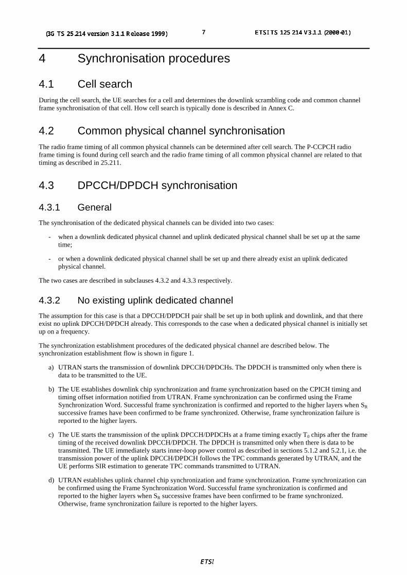
The synchronization establishment procedures of the dedicated physical channel are described below. Thesynchronization establishment flow is shown in figure 1.
a) UTRAN starts the transmission of downlink DPCCH/DPDCHs. The DPDCH is transmitted only when there isdata to be transmitted to the UE.
b) The UE establishes downlink chip synchronization and frame synchronization based on the CPICH timing andtiming offset information notified from UTRAN. Frame synchronization can be confirmed using the FrameSynchronization Word. Successful frame synchronization is confirmed and reported to the higher layers when SR
successive frames have been confirmed to be frame synchronized. Otherwise, frame synchronization failure isreported to the higher layers.
c) The UE starts the transmission of the uplink DPCCH/DPDCHs at a frame timing exactly T0 chips after the frametiming of the received downlink DPCCH/DPDCH. The DPDCH is transmitted only when there is data to betransmitted. The UE immediately starts inner-loop power control as described in sections 5.1.2 and 5.2.1, i.e. thetransmission power of the uplink DPCCH/DPDCH follows the TPC commands generated by UTRAN, and theUE performs SIR estimation to generate TPC commands transmitted to UTRAN.
d) UTRAN establishes uplink channel chip synchronization and frame synchronization. Frame synchronization canbe confirmed using the Frame Synchronization Word. Successful frame synchronization is confirmed andreported to the higher layers when SR successive frames have been confirmed to be frame synchronized.Otherwise, frame synchronization failure is reported to the higher layers.
3GPP
3G TS 25.214 V3.1.1 (1999-12)83G TS 25.214 version 3.1.0
Start downlinksynchronisation process
Establish chip and framesynchronisation and report
status to higher layers
Start transmission ofuplink channels
Start transmission ofdownlink channels
Start uplinksynchronisation process
Establish chip and framesynchronisation and report
status to higher layers
UE UTRAN
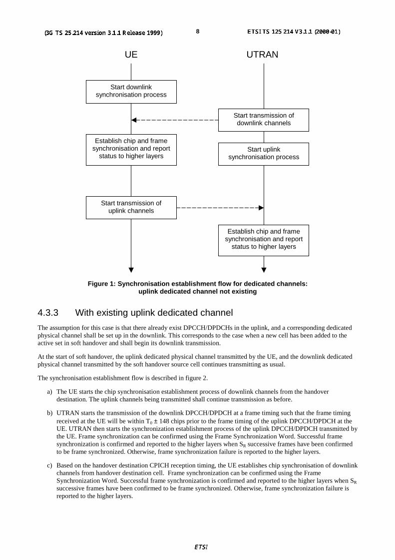
Figure 1: Synchronisation establishment flow for dedicated channels:uplink dedicated channel not existing
4.3.3 With existing uplink dedicated channel
The assumption for this case is that there already exist DPCCH/DPDCHs in the uplink, and a corresponding dedicatedphysical channel shall be set up in the downlink. This corresponds to the case when a new cell has been added to theactive set in soft handover and shall begin its downlink transmission.
At the start of soft handover, the uplink dedicated physical channel transmitted by the UE, and the downlink dedicatedphysical channel transmitted by the soft handover source cell continues transmitting as usual.
The synchronisation establishment flow is described in figure 2.
a) The UE starts the chip synchronisation establishment process of downlink channels from the handoverdestination. The uplink channels being transmitted shall continue transmission as before.
b) UTRAN starts the transmission of the downlink DPCCH/DPDCH at a frame timing such that the frame timingreceived at the UE will be within T0 ± 148 chips prior to the frame timing of the uplink DPCCH/DPDCH at theUE. UTRAN then starts the synchronization establishment process of the uplink DPCCH/DPDCH transmitted bythe UE. Frame synchronization can be confirmed using the Frame Synchronization Word. Successful framesynchronization is confirmed and reported to the higher layers when SR successive frames have been confirmedto be frame synchronized. Otherwise, frame synchronization failure is reported to the higher layers.
c) Based on the handover destination CPICH reception timing, the UE establishes chip synchronisation of downlinkchannels from handover destination cell. Frame synchronization can be confirmed using the FrameSynchronization Word. Successful frame synchronization is confirmed and reported to the higher layers when SR
successive frames have been confirmed to be frame synchronized. Otherwise, frame synchronization failure isreported to the higher layers.

3GPP
3G TS 25.214 V3.1.1 (1999-12)93G TS 25.214 version 3.1.0
Start downlinksynchronisation process
Establish chip and framesynchronisation and report
status to higher layers
Start transmission ofdownlink channels
Start uplinksynchronisation process
Establish chip and framesynchronisation and report
status to higher layers
UE UTRAN
Figure 2: Synchronisation establishment flow for dedicated channels:uplink dedicated channel already existing
4.3.4 Transmission timing adjustments
During a connection the UE may adjust its DPDCH/DPCCH transmission time instant.
If the receive timing for any downlink DPCCH/DPDCH in the current active set has drifted, so the time betweenreception of the downlink DPCCH/DPDCH in question and transmission of uplink DPCCH/DPDCH lies outside thevalid range, L1 shall inform higher layers of this, so that the network can be informed of this and downlink timing canbe adjusted by the network.
NOTE: The maximum rate of uplink TX time adjustment, and the valid range for the time between downlinkDPCCH/DPDCH reception and uplink DPCCH/DPDCH transmission in the UE is to be specified byRAN WG4.
5 Power control
5.1 Uplink power control
5.1.1 PRACH
5.1.1.1 General
The power control during the physical random access procedure is described in clause 6. The setting of power of themessage control and data parts is described in the next sub-clause.
5.1.1.2 Setting of PRACH control and data part power difference
The message part of the uplink PRACH channel shall employ gain factors to control the control/data part relative powersimilar to the uplink dedicated physical channels. Hence, section 5.1.2.4 applies also for the RACH message part, withthe differences that:

3GPP
3G TS 25.214 V3.1.1 (1999-12)103G TS 25.214 version 3.1.0
- βc is the gain factor for the control part (similar to DPCCH),
- βd is the gain factor for the data part (similar to DPDCH),
- no inner loop power control is performed.
5.1.2 DPCCH/DPDCH
5.1.2.1 General
The uplink transmit power control procedure controls simultaneously the power of a DPCCH and its correspondingDPDCHs. The power control loop adjusts the power of the DPCCH and DPDCHs with the same amount. The relativetransmit power offset between DPCCH and DPDCHs is determined by the network and signalled to the UE usinghigher layer signalling.
5.1.2.2 Ordinary transmit power control
5.1.2.2.1 General
The initial uplink transmit power is set by higher layers.
By means of higher layer signalling, a maximum transmission power for uplink inner-loop power control may be set toa lower value than what the terminal power class is capable of. Power control shallbe performed within the allowedrange.
The uplink inner-loop power control adjusts the UE transmit power in order to keep the received uplink signal-to-interference ratio (SIR) at a given SIR target, SIRtarget.
The serving cells (cells in the active set) should estimate signal-to-interference ratio SIRest of the received uplink DPCH. The serving cells then generates TPC commands and transmits the commands once per slot according to the followingrule: if SIRest > SIRtarget then the TPC command to transmit is "0", while if SIRest < SIRtarget then the TPC command totransmit is "1".
Upon reception of one or more TPC commands in a slot, the UE derives a single TPC command, TPC_cmd, for eachslot, combining multiple TPC commands if more than one is received in a slot. Two algorithms shall be supported bythe UE for deriving a TPC_cmd, as described in subclauses 5.1.2.2.2 and 5.1.2.2.3. Which of these two algorithms isused is an UE-specific parameter and is under the control of the UTRAN.
The step size ∆TPC is a UE specific parameter, under the control of the UTRAN that can have the values 1 dB or 2 dB.
After deriving of the combined TPC command TPC_cmd using one of the two supported algorithms, the UE shalladjust the transmit power of the uplink dedicated physical channels with a step of ∆TPC dB according to the TPCcommand. If TPC_cmd equals 1 then the transmit power of the uplink DPCCH and uplink DPDCHs shall be increasedby ∆TPC dB. If TPC_cmd equals -1 then the transmit power of the uplink DPCCH and uplink DPDCHs shall bedecreased by ∆TPC dB. If TPC_cmd equals 0 then the transmit power of the uplink DPCCH and uplink DPDCHs shallbe unchanged.
Any power increase or decrease shall take place immediately before the start of the pilot field on the DPCCH.
5.1.2.2.1.1 Out of synchronisation handling
The UE shall monitor the active link, or links in case of soft handover, to determine if the link is out-of-synchronisationor not. Depending on the situation the UE may use for example CPICH or pilot symbol patterns or combination thereoff to determine the link synchronisation status.
If N_out_synch_frames_1 frames that have passed have been found to be out-of-synchronisation for all links, the UEshall turn off uplink transmission. The value for N_out_synch_frames_1 is given by the higher layers.
If N_out_synch_frames_2 is detected to be out-of-synchronisation, the UE shall maintain the output power level,controlled by inner loop power control, constant while out-of-synchronisation state lasts or untilN_out_synch_frames_1 reached when the transmission shall be turned off. The TPC command sent in the uplink shallbe set as "1" during the period of out-of-synchronisation.

3GPP
3G TS 25.214 V3.1.1 (1999-12)113G TS 25.214 version 3.1.0
5.1.2.2.2 Algorithm 1 for processing TPC commands
5.1.2.2.2.1 Derivation of TPC_cmd when only one TPC command is received in each slot
When a UE is not in soft handover, only one TPC command will be received in each slot. In this case, the value ofTPC_cmd is derived as follows:
- If the received TPC command is equal to 0 then TPC_cmd for that slot is –1.
- If the received TPC command is equal to 1, then TPC_cmd for that slot is 1.
5.1.2.2.2.2 Combining of TPC commands known to be the same
When a UE is in soft handover, multiple TPC commands may be received in each slot from different cells in the activeset. In some cases, the UE has the knowledge that some of the transmitted TPC commands in a slot are the same. This isthe case e.g. with receiver diversity or so called softer handover when the UTRAN transmits the same command in allthe serving cells the UE is in softer handover with. For these cases, the TPC commands known to be the same arecombined into one TPC command, to be further combined with other TPC commands as described in subclause5.1.2.2.2.3.
5.1.2.2.2.3 Combining of TPC commands not known to be the same
In general in case of soft handover, the TPC commands transmitted in the same slot in the different cells may bedifferent.
This subclause describes the general scheme for combination of the TPC commands not known to be the same and thenprovides an example of such a scheme. It is to be further decided what should be subject to detailed standardisation,depending on final requirements. The example might be considered as the scheme from which minimum requirementwill be derived or may become the mandatory algorithm.
5.1.2.2.2.3.1 General scheme
First, the UE shall conduct a soft symbol decision on each of the power control commands TPCi, where i = 1, 2, …, Nand N is the number of TPC commands not known to be the same, that may be the result of a first phase of combinationaccording to subclause 5.1.2.2.2.2.
Then the UE assigns to each of the TPCi command a reliability figure Wi, where Wi is the soft symbol decision obtained
above. Finally, the UE derives a combined TPC command, TPC_cmd, as a function γ of all the N power controlcommands TPCi and reliability estimates Wi:
TPC_cmd = γ (W1, W2, … WN, TPC1, TPC2, …, TPCN), where TPC_cmd can take the values 1 or -1.
5.1.2.2.3 Algorithm 2 for processing TPC commands
NOTE: Algorithm 2 makes it possible to emulate smaller step sizes than the minimum power control stepspecified in section 5.1.2.2.1, or to turn off uplink power control by transmitting an alternating series ofTPC commands.
5.1.2.2.3.1 Derivation of TPC_cmd when only one TPC command is received in each slot
When a UE is not in soft handover, only one TPC command will be received in each slot. In this case, the UE shallprocess received TPC commands on a 5-slot cycle, where the sets of 5 slots shall be aligned to the frame boundaries andthere shall be no overlap between each set of 5 slots.
The value of TPC_cmd is derived as follows:
- For the first 4 slots of a set, TPC_cmd = 0.
- For the fifth slot of a set, the UE uses hard decisions on each of the 5 received TPC commands as follows:
- If all 5 hard decisions within a set are 1 then TPC_cmd = 1 in the 5th slot.
- If all 5 hard decisions within a set are 0 then TPC_cmd = -1 in the 5th slot.

3GPP
3G TS 25.214 V3.1.1 (1999-12)123G TS 25.214 version 3.1.0
- Otherwise, TPC_cmd = 0 in the 5th slot.
5.1.2.2.3.2 Combining of TPC commands known to be the same
When a UE is in soft handover, multiple TPC commands may be received in each slot from different cells in the activeset. In some cases, the UE has the knowledge that some of the transmitted TPC commands in a slot are the same. This isthe case e.g. with receiver diversity or so called softer handover when the UTRAN transmits the same command in allthe serving cells the UE is in softer handover with. For these cases, the TPC commands known to be the same arecombined into one TPC command, to be processed and further combined with any other TPC commands as described insubclause 5.1.2.2.3.3.
5.1.2.2.3.3 Combining of TPC commands not known to be the same
In general in case of soft handover, the TPC commands transmitted in the same slot in the different cells may bedifferent.
This subclause describes the general scheme for combination of the TPC commands not known to be the same and thenprovides an example of such scheme. It is to be further decided what should be subject to detailed standardisation,depending on final requirements. The example might be considered as the scheme from which minimum requirementwill be derived or may become the mandatory algorithm.
5.1.2.2.3.3.1 General scheme
The UE shall make a hard decision on the value of each TPCi, where i = 1, 2, …, N and N is the number of TPCcommands not known to be the same, that may be the result of a first phase of combination according to subclause5.1.2.2.3.2..
The UE shall follow this procedure for 3 consecutive slots, resulting in N hard decisions for each of the 3 slots.
The sets of 3 slots shall be aligned to the frame boundaries and there shall be no overlap between each set of 3 slots.
The value of TPC_cmd is zero for the first 2 slots. After 3 slots have elapsed, the UE shall determine the value ofTPC_cmd for the third slot in the following way:
The UE first determines one temporary TPC command, TPC_tempi, for each of the N sets of 3 TPC commands asfollows:
- If all 3 hard decisions within a set are "1", TPC_tempi = 1
- If all 3 hard decisions within a set are "0", TPC_tempi = -1
- Otherwise, TPC_tempi = 0
Finally, the UE derives a combined TPC command for the third slot, TPC_cmd, as a function γ of all the N temporarypower control commands TPC_tempi:
TPC_cmd(3rd slot) = γ (TPC_temp1, TPC_temp2, …, TPC_tempN), where TPC_cmd(3rd slot) can take the values 1, 0 or–1.
5.1.2.2.3.3.2 Example of the scheme
A particular example of the scheme is obtained when using the following definition of the function γ:
TPC_cmd is set to 1 if 5.0_1
1
>∑=
N
iitempTPC
N.
TPC_cmd is set to -1 if 5.0_1
1
−<∑=
N
iitempTPC
N.
Otherwise, TPC_cmd is set to 0.

3GPP
3G TS 25.214 V3.1.1 (1999-12)133G TS 25.214 version 3.1.0
5.1.2.3 Transmit power control in compressed mode
The aim of uplink power control in downlink or/and uplink compressed mode is to recover as fast as possible a signal-to-interference ratio (SIR) close to the target SIR after each transmission gap.
In downlink compressed mode, no power control is applied during transmission gaps, since no downlink TPC commandis sent. Thus, the transmit powers of the uplink DPDCH(s) and DPCCH are not changed during the transmission gaps.
In simultaneous downlink and uplink compressed mode, the transmission of uplink DPDCH(s) and DPCCH is stoppedduring transmission gaps.
The initial transmit power of each uplink DPDCH and DPCCH after the transmission gap is equal to the power beforethe gap, but with an offset ∆ RESUME. The value of ∆ RESUME (in dB) is determined according to the Power ResumeMode (PRM). The PRM is a UE specific parameter, which is signalled by the network with the other parameters of thedownlink compressed mode (see TS 25.215). The different modes are summarised in table 1.
Table 1: Power control resume modes during compressed mode
Power Resume Mode Description0 ∆ RESUME = 01 ∆ RESUME = Int[δ last / ∆ TPCmin ] ∆ TPCmin
Here Int[ ] means round to the nearest integer and ∆ TPCmin is the minimum power control step size supported by theUE. δ last is the power offset computed at the last slot before the transmission gap according to the following recursiverelations, which are, executed every slot during uplink transmission:
lastprevious
TPClastpreviouslast cmdTPC
δδδδ
=
∆−= _96875.09375.0
TPC_cmd is the power control command executed by the UE in the last slot before the transmission gap. δprevious is thepower offset computed for the previous slot. The value of δprevious shall be initialised to zero when a DCH is activated, orduring the first slot after a transmission gap.
After each transmission gap, 2 modes are possible for the power control algorithm. The power control mode (PCM) isfixed and signalled with the other parameters of the downlink compressed mode (see TS 25.215). The different modesare summarised in the table 2:
Table 2: Power control modes during compressed mode
Mode Description0 Ordinary transmit power control (see subclause 5.1.2.2) is applied with step size ∆TPC
1 Ordinary transmit power control is applied using algorithm 1 (see subclause 5.1.2.2.2) with stepsize ∆RP-TPC during RPL slots after each transmission gap.
For mode 0, the step size is not changed and the ordinary transmit power control is still applied during compressedmode (see subclause 5.1.2.2), using the same algorithm for processing TPC commands as in normal mode (see section5.1.2.2.2 and 5.1.2.2.3).
For mode 1, during RPL slots after each transmission gap, called the recovery period, power control algorithm 1 isapplied with a step size ∆RP-TPC instead of ∆TPC.
∆RP-TPC is called recovery power control step size and is expressed in dB. If algorithm 1 (section 5.1.2.2.2) is used innormal mode, ∆RP-TPC is equal to the minimum value of 3 dB and 2∆TPC. If algorithm 2 (section 5.1.2.2.3) is used innormal mode, ∆RP-TPC is equal to 1 dB.
RPL is called recovery period length and is expressed in number of slots. RPL is fixed and equal to the minimum valueof TGL and 7 slots.
After the recovery period, ordinary transmit power control resumes using the same algorithm and step size as used innormal mode before the transmission gap.

3GPP
3G TS 25.214 V3.1.1 (1999-12)143G TS 25.214 version 3.1.0
If algorithm 2 (section 5.1.2.2.3) is being used in normal mode, the sets of slots over which the TPC commands areprocessed (in section 5.1.2.2.2.3.1) shall remain aligned to the frame boundaries in the compressed frame. In both mode0 or mode 1, if the transmission gap or the recovery period results in any incomplete sets of TPC commands, noTPC_tempi command will be determined for those sets of slots which are incomplete, and there will be no change intransmit power level for those sets of slots.
During compressed mode and the recovery period after compressed mode, regardless of the offset ∆ RESUME and the stepsize ∆RP-TPC, the UE transmit power shall not exceed the maximum allowed transmission power set by higher layersignalling.
5.1.2.4 Transmit power control in DPCCH power control preamble
A power control preamble may be used for initialisation of a DCH. Both the UL and DL DPCCHs shall be transmittedduring the uplink power control preamble. The UL DPDCH shall not commence before the end of the power controlpreamble.
The length of the power control preamble is a UE-specific parameter signalled by the network, and can take the values0 slots or 8 slots.
The inner power control loop acts on the UL DPCCH during the preamble in the same way as described in section5.1.2.2.1.
The initial power control step size used in the power control preamble differs from that used after the preamble in thefollowing way. If algorithm 1 is to be used after the preamble to calculate the value of TPC_cmd, then the initial stepsize in the power control preamble is ∆TPC-init, where ∆TPC-init is equal to the minimum value out of 3 dB and 2∆TPC. Ifalgorithm 2 is to be used after the preamble to calculate the value of TPC_cmd, then initially in the power controlpreamble algorithm 1 is used with a step size of 2dB. In either case, the power control algorithm and step size revert tothose used for the main part of the transmission as soon as the sign of TPC_cmd reverses for the first time, or at the endof the power control preamble if the power control preamble ends first.
5.1.2.5 Setting of the uplink DPCCH/DPDCH power difference
5.1.2.5.1 General
The uplink DPCCH and DPDCH(s) are transmitted on different codes as defined in section 4.2.1 of TS 25.213. Thegain factors βc and βd may vary for each TFC. There are two ways of controlling the gain factors of the DPCCH codeand the DPDCH codes for different TFCs in normal (non-compressed) frames:
− βc and βd are signalled for the TFC, or
− βc and βd is computed for the TFC, based on the signalled settings for a reference TFC.
Combinations of the two above methods may be used to associate βc and βd values to all TFCs in the TFCS. The twomethods are described in sections 5.1.2.4.2 and 5.1.2.4.3 respectively. Several reference TFCs may be signalled fromhigher layers.
The gain factors may vary on radio frame basis depending on the current TFC used. Further, the setting of gain factorsis independent of the inner loop power control. This means that at the start of a frame, the gain factors are determinedand the inner loop power control step is applied on top of that.
Appropriate scaling of the output power shall be performed by the UE, so that the output DPCCH power follows theinner loop power control with power steps of ±∆TPC dB.
The gain factors during compressed frames are based on the gain factors defined in normal frames, as specified in5.1.2.5.4.
5.1.2.5.2 Signalled gain factors
When the gain factors βc and βd are signalled by higher layers for a certain TFC, the signalled values are used directlyfor weighting of DPCCH and DPDCH(s).
3GPP
3G TS 25.214 V3.1.1 (1999-12)153G TS 25.214 version 3.1.0
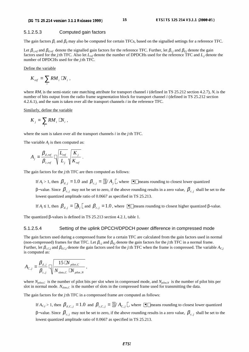
5.1.2.5.3 Computed gain factors
The gain factors βc and βd may also be computed for certain TFCs, based on the signalled settings for a reference TFC.
Let βc,ref and βd,ref denote the signalled gain factors for the reference TFC. Further, let βc,j and βd,j denote the gainfactors used for the j:th TFC. Also let Lref denote the number of DPDCHs used for the reference TFC and L,j denote thenumber of DPDCHs used for the j:th TFC.
Define the variable
∑ ⋅=i
iiref NRMK ,
where RMi is the semi-static rate matching attribute for transport channel i (defined in TS 25.212 section 4.2.7), Ni is thenumber of bits output from the radio frame segmentation block for transport channel i (defined in TS 25.212 section4.2.6.1), and the sum is taken over all the transport channels i in the reference TFC.
Similarly, define the variable
∑ ⋅=i
iij NRMK ,
where the sum is taken over all the transport channels i in the j:th TFC.
The variable Aj is then computed as:
ref
j
j
ref
refc
refdj K
K
L
LA ⋅=
,
,
ββ
.
The gain factors for the j:th TFC are then computed as follows:
If Aj > 1, then 0.1, =jdβ and jjc A/1, =β , where • means rounding to closest lower quantized
β−value. Since jc,β may not be set to zero, if the above rounding results in a zero value, jc,β shall be set to the
lowest quantized amplitude ratio of 0.0667 as specified in TS 25.213.
If Aj ≤ 1, then jjd A=,β and 0.1, =jcβ , where • means rounding to closest higher quantized β-value.
The quantized β-values is defined in TS 25.213 section 4.2.1, table 1.
5.1.2.5.4 Setting of the uplink DPCCH/DPDCH power difference in compressed mode
The gain factors used during a compressed frame for a certain TFC are calculated from the gain factors used in normal(non-compressed) frames for that TFC. Let βc,j and βd,j denote the gain factors for the j:th TFC in a normal frame.Further, let βc,C,j and βd,C,j denote the gain factors used for the j:th TFC when the frame is compressed. The variable AC,j
is computed as:
NpilotCslots
Cpilot
jc
jdjC NN
NA
,,
,
,
,,
15
⋅⋅
⋅=ββ
,
where Npilot,C is the number of pilot bits per slot when in compressed mode, and Npilot,N is the number of pilot bits perslot in normal mode. Nslots,C is the number of slots in the compressed frame used for transmitting the data.
The gain factors for the j:th TFC in a compressed frame are computed as follows:
If AC,j > 1, then 0.1,, =jCdβ and jCjCc A ,,, /1=β , where • means rounding to closest lower quantized
β−value. Since jc,β may not be set to zero, if the above rounding results in a zero value, jc,β shall be set to the
lowest quantized amplitude ratio of 0.0667 as specified in TS 25.213.

3GPP
3G TS 25.214 V3.1.1 (1999-12)163G TS 25.214 version 3.1.0
If AC,j ≤ 1, then jCjCd A ,,, =β and 0.1,, =jCcβ , where • means rounding to closest higher quantized β-
value.
The quantized β-values is defined in TS 25.213 section 4.2.1, table 1.
Appropriate scaling of the output power shall be performed by the UE, so that the output DPCCH power follows theinner loop power control with power steps of ±∆TPC dB (±∆RP-TPC dB during the recovery period) with an additionalpower offset during a compressed frame of Npilot,N / Npilot,C.
5.1.3 PCPCH
This section describes the power control procedures for the PCPCH. The CPCH access procedure is described in section6.2.
5.1.3.1 Power control in the message part
The uplink inner-loop power control adjusts the UE transmit power in order to keep the received uplink signal-to-interference ratio (SIR) at a given SIR target, SIRtarget, which is set by the higher layer outer loop.
The network should estimate the signal-to-interference ratio SIRest of the received PCPCH . The network then generatesTPC commands and transmits the commands once per slot according to the following rule: if SIRest > SIRtarget then theTPC command to transmit is "0", while if SIRest < SIRtarget then the TPC command to transmit is "1".
The UE derives a TPC command, TPC_cmd, for each slot. Two algorithms shall be supported by the UE for deriving aTPC_cmd, as described in subclauses 5.1.2.2.2.1 and 5.1.2.2.3.1. Which of these two algorithms is used is a higher-layer parameter under the control of the UTRAN.
The step size ∆TPC is a higher-layer parameter under the control of the UTRAN, that can have the values 1 dB or 2 dB.
After deriving the TPC command TPC_cmd using one of the two supported algorithms, the UE shall adjust thetransmit power of the uplink PCPCH with a step of ∆TPC dB according to the TPC command. If TPC_cmd equals 1 thenthe transmit power of the uplink PCPCH shall be increased by ∆TPC dB. If TPC_cmd equals -1 then the transmit powerof the uplink PCPCH shall be decreased by ∆TPC dB. If TPC_cmd equals 0 then the transmit power of the uplinkPCPCH shall be unchanged.
Any power increase or decrease shall take place immediately before the start of the pilot field on the PCPCH controlchannel.
5.1.3.2 Power control in the power control preamble
The UE commences the power control preamble using the same power level as was used for the CD preamble.
The initial power control step size used in the power control preamble differs from that used in the message part: ifinner loop power control algorithm 1 is to be used in the message part, then the initial step size in the power controlpreamble is ∆TPC-init, where ∆TPC-init is equal to the minimum value out of 3 dB and 2∆TPC, where ∆TPC is the powercontrol step size used for the message part. If inner loop power control algorithm 2 is to be used in the message part,then inner loop power control algorithm 1 is used initially in the power control preamble, with a step size of 2dB. Ineither case, the power control algorithm and step size revert to those used for the message part as soon as the sign of theTPC commands reverses for the first time.
5.2 Downlink power controlThe transmit power of the downlink channels is determined by the network. In general the ratio of the transmit powerbetween different downlink channels is not specified and may change with time. However, regulations exist asdescribed in the following sub-clauses.
3GPP
3G TS 25.214 V3.1.1 (1999-12)173G TS 25.214 version 3.1.0
5.2.1 DPCCH/DPDCH
5.2.1.1 General
The downlink transmit power control procedure controls simultaneously the power of a DPCCH and its correspondingDPDCHs. The power control loop adjusts the power of the DPCCH and DPDCHs with the same amount, i.e. therelative power difference between the DPCCH and DPDCHs is not changed.
The relative transmit power offset between DPCCH fields and DPDCHs is determined by the network The TFCI, TPCand pilot fields of the DPCCH are offset relative to the DPDCHs power by PO1, PO2 and PO3 dB respectively. Thepower offsets may vary in time.
5.2.1.2 Ordinary transmit power control
5.2.1.2.1 General
The downlink inner-loop power control adjusts the network transmit power in order to keep the received downlink SIRat a given SIR target, SIRtarget. A higher layer outer loop adjusts SIRtarget independently for each connection.
The UE should estimate the received downlink DPCCH/DPDCH power of the connection to be power controlled.Simultaneously, the UE should estimate the received interference. The obtained SIR estimate SIRest is then used by theUE to generate TPC commands according to the following rule: if SIRest > SIRtarget then the TPC command to transmitis "0", requesting a transmit power decrease, while if SIRest < SIRtarget then the TPC command to transmit is "1",requesting a transmit power increase.
When the UE is not in soft handover the TPC command generated is transmitted in the first available TPC field in theuplink DPCCH.
When the UE is in soft handover it should check the downlink power control mode (DPC_MODE) before generatingthe TPC command
- if DPC_MODE = 0 : the UE sends a unique TPC command in each slot and the TPC command generated istransmitted in the first available TPC field in the uplink DPCCH
- if DPC_MODE = 1 : the UE repeats the same TPC command over 3 slots and the new TPC command istransmitted such that there is a new command at the beginning of the frame.
The DPC_MODE parameter is a UE specific parameter controlled by the UTRAN.
As a response to the received TPC commands, UTRAN may adjust the downlink DPCCH/DPDCH power. The averagepower of transmitted DPDCH symbols over one timeslot shall not exceed Maximum_DL_Power(dBm), nor shall it bebelow Minimum_DL_Power (dBm). Transmitted DPDCH symbol means here a complex QPSK symbol beforespreading which does not contain DTX.
NOTE: It should still be clarified whether Maximum_DL_Power and Minimum_DL_Power are defined for onecode or for one CCTrCH
Changes of power shall be a multiple of the minimum step size ∆TPC,min dB. It is mandatory for UTRAN to support∆TPC,min of 1 dB, while support of 0.5 dB is optional.
When SIR measurements cannot be performed due to downlink out-of-synchronisation, the TPC command transmittedshall be set as "1" during the period of out-of-synchronisation.
5.2.1.2.2 Adjustment loop
UTRAN may further employ adjustment loop, in which they change their calculated transmission powers P(i) in everyslot according to the following equation:
P(i+1) = P(i) + SINNER(i) + SADJ(i)
SADJ(i) = sign{(1 – r)(PREF – P(i))} min{|(1 – r)(PREF – P(i))|, SADJ_MAX}
where

3GPP
3G TS 25.214 V3.1.1 (1999-12)183G TS 25.214 version 3.1.0
P(i): calculated transmission power of UTRAN access point in dBm,
SINNER(i): inner loop control in dB,
SADJ(i): adjustment loop control in dB,
sign{x}: sign function of the value x, i.e. +1 when x>0, 0 when x=0, and –1 when x<0,
r: convergence coefficient (0 ≤ r ≤ 1),
PREF: reference transmission power in dBm,
SADJ_MAX: maximum power change limit by adjustment loop in dB.
The actual change in the transmitted power level due to the adjustment loop is a value which is the nearest allowed TPCstep to SADJ(i). The parameters, r, PREF, and SADJ_MAX shall be signalled by higher layers. SADJ_MAX shall be a multiple ofthe minimum step size ¨TPC,min dB.
5.2.1.3 Power control in compressed mode
The aim of downlink power control in uplink or/and downlink compressed mode is to recover as fast as possible asignal-to-interference ratio (SIR) close to the target SIR after each transmission gap.
The UE behaviour is the same in compressed mode as in normal mode, described in subclause 5.2.1.2, i.e. TPCcommands should be generated based on the estimated received SIR.
The UTRAN behaviour during compressed mode is not specified. As an example, the algorithm can be similar to uplinkpower control in downlink compressed mode as described in sub-clause 5.1.2.3.
In downlink compressed mode or in simultaneous downlink and uplink compressed mode, the transmission of downlinkDPCCH and DPDCH(s) is stopped.
5.2.1.4 Site selection diversity transmit power control
5.2.1.4.1 General
Site selection diversity transmit power control (SSDT) is an optional macro diversity method in soft handover mode.
Operation is summarised as follows. The UE selects one of the cells from its active set to be ‘primary’, all other cellsare classed as ‘non primary’. The main objective is to transmit on the downlink from the primary cell, thus reducing theinterference caused by multiple transmissions in a soft handover mode. A second objective is to achieve fast siteselection without network intervention, thus maintaining the advantage of the soft handover. In order to select a primarycell, each cell is assigned a temporary identification (ID) and UE periodically informs a primary cell ID to theconnecting cells. The non-primary cells selected by UE switch off the transmission power. The primary cell ID isdelivered by UE to the active cells via uplink FBI field. SSDT activation, SSDT termination and ID assignment are allcarried out by higher layer signalling.
5.2.1.4.1.1 Definition of temporary cell identification
Each cell is given a temporary ID during SSDT and the ID is utilised as site selection signal. The ID is given a binarybit sequence. There are three different lengths of coded ID available denoted as "long", "medium" and "short". Thenetwork decides which length of coded ID is used. Settings of ID codes for 1-bit and 2-bit FBI are exhibited in table 3and table 4, respectively.

3GPP
3G TS 25.214 V3.1.1 (1999-12)193G TS 25.214 version 3.1.0
Table 3: Settings of ID codes for 1 bit FBI
ID codeID label "long" "medium" "short"
a 000000000000000 0000000(0) 00000b 111111111111111 1111111(1) 11111c 000000001111111 0000111(1) 00011d 111111110000000 1111000(0) 11100e 000011111111000 0011110(0) 00110f 111100000000111 1100001(1) 11001g 001111000011110 0110011(0) 01010h 110000111100001 1001100(1) 10101
Table 4: Settings of ID codes for 2 bit FBI
ID code(Column and Row denote slot position and FBI-bit position.)
ID label "long" "medium" "short"a 0000000(0)
0000000(0)000(0)000(0)
000000
b 1111111(1)1111111(1)
111(1)111(1)
111111
c 0000000(0)1111111(1)
000(0)111(1)
000111
d 1111111(1)0000000(0)
111(1)000(0)
111000
e 0000111(1)1111000(0)
001(1)110(0)
001100
f 1111000(0)0000111(1)
110(0)001(1)
110011
g 0011110(0)0011110(0)
011(0)011(0)
010010
h 1100001(1)1100001(1)
100(1)100(1)
101101
ID must be terminated within a frame. If FBI space for sending a given ID cannot be obtained within a frame, hence ifthe entire ID is not transmitted within a frame but must be split over two frames, the last bit(s) of the ID is(are)punctured. The relating bit(s) to be punctured are shown with brackets in table 3 and table 4.
5.2.1.4.2 TPC procedure in UE
The TPC procedure of the UE in SSDT is identical to that described in subclause5.2.1.2 or 5.2.1.3 in compressed mode.
5.2.1.4.3 Selection of primary cell
The UE selects a primary cell periodically by measuring the RSCP of CPICHs transmitted by the active cells. The cellwith the highest CPICH RSCP is detected as a primary cell.
5.2.1.4.4 Delivery of primary cell ID
The UE periodically sends the ID code of the primary cell via portion of the uplink FBI field assigned for SSDT use(FBI S field). A cell recognises its state as non-primary if the following conditions are fulfilled simultaneously:
- the received primary ID code does not match with the own ID code,
- the received uplink signal quality satisfies a quality threshold, Qth, a parameter defined by the network.
- and, when the uplink link compressed mode, does not results in excessive levels of puncturing on the coded ID.The acceptable level of puncturing on the coded ID is less than (int)NID/3 symbols in the coded ID (where NID isthe length of the coded ID).
Otherwise the cell recognises its state as primary.
3GPP
3G TS 25.214 V3.1.1 (1999-12)203G TS 25.214 version 3.1.0
The state of the cells (primary or non-primary) in the active set with update synchronous. If a cell receives the lastportion of the coded ID in uplink slot #j, the state of cell is updated in downlink slot#{(j+1+Tos) mod 15}. Where Tos isdefined as a constant of 2 time slots. The updating of cell state is unchanged by the operation of downlink compressedmode.
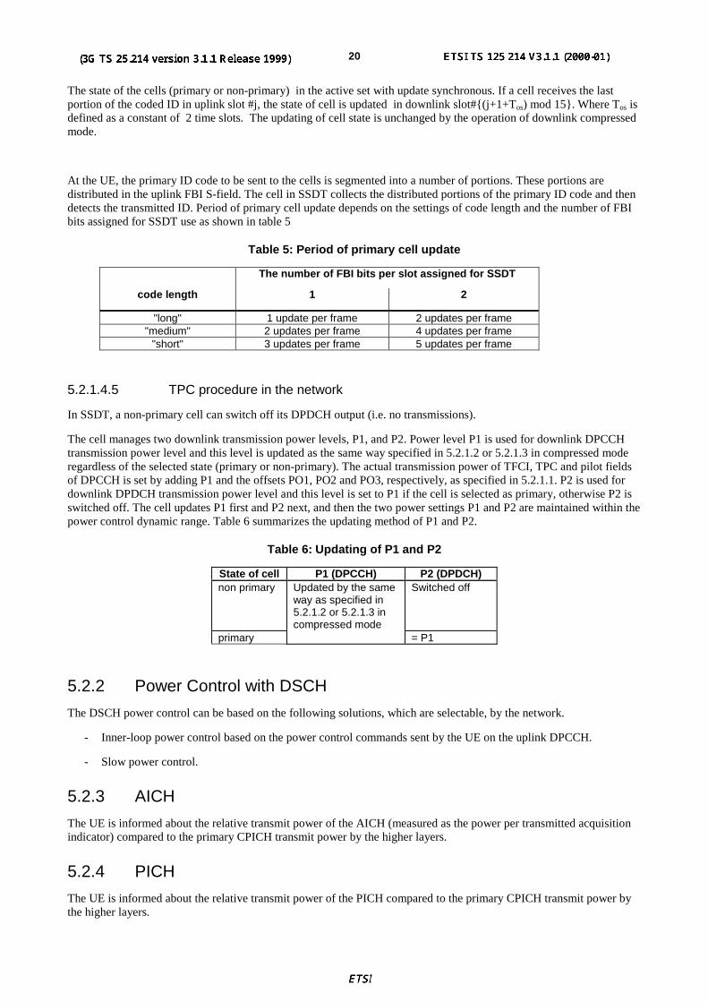
At the UE, the primary ID code to be sent to the cells is segmented into a number of portions. These portions aredistributed in the uplink FBI S-field. The cell in SSDT collects the distributed portions of the primary ID code and thendetects the transmitted ID. Period of primary cell update depends on the settings of code length and the number of FBIbits assigned for SSDT use as shown in table 5
Table 5: Period of primary cell update
The number of FBI bits per slot assigned for SSDT
code length 1 2
"long" 1 update per frame 2 updates per frame"medium" 2 updates per frame 4 updates per frame
"short" 3 updates per frame 5 updates per frame
5.2.1.4.5 TPC procedure in the network
In SSDT, a non-primary cell can switch off its DPDCH output (i.e. no transmissions).
The cell manages two downlink transmission power levels, P1, and P2. Power level P1 is used for downlink DPCCHtransmission power level and this level is updated as the same way specified in 5.2.1.2 or 5.2.1.3 in compressed moderegardless of the selected state (primary or non-primary). The actual transmission power of TFCI, TPC and pilot fieldsof DPCCH is set by adding P1 and the offsets PO1, PO2 and PO3, respectively, as specified in 5.2.1.1. P2 is used fordownlink DPDCH transmission power level and this level is set to P1 if the cell is selected as primary, otherwise P2 isswitched off. The cell updates P1 first and P2 next, and then the two power settings P1 and P2 are maintained within thepower control dynamic range. Table 6 summarizes the updating method of P1 and P2.
Table 6: Updating of P1 and P2
State of cell P1 (DPCCH) P2 (DPDCH)non primary Updated by the same
way as specified in5.2.1.2 or 5.2.1.3 incompressed mode
Switched off
primary = P1
5.2.2 Power Control with DSCH
The DSCH power control can be based on the following solutions, which are selectable, by the network.
- Inner-loop power control based on the power control commands sent by the UE on the uplink DPCCH.
- Slow power control.
5.2.3 AICH
The UE is informed about the relative transmit power of the AICH (measured as the power per transmitted acquisitionindicator) compared to the primary CPICH transmit power by the higher layers.
5.2.4 PICH
The UE is informed about the relative transmit power of the PICH compared to the primary CPICH transmit power bythe higher layers.

3GPP
3G TS 25.214 V3.1.1 (1999-12)213G TS 25.214 version 3.1.0
6 Random access procedure
6.1 Physical random access procedureThe physical random access procedure described in this section is initiated upon request of a PHY-Data-REQ primitivefrom the MAC sublayer (cf. TS 25.321).
Before the physical random-access procedure can be initiated, Layer 1 shall receive the following information from thehigher layers (RRC) :
- The preamble scrambling code
- The message length in time, either 10 or 20 ms
- The AICH_Transmission_Timing parameter [0 or 1].
- The available signatures and RACH sub-channel groups for each Access Service Class (ASC), where a sub-channel group is defined as a group of some of the sub-channels defined in Section 6.1.1.
- The power-ramping factor Power_Ramp_Step [integer > 0].
- The parameter Preamble_Retrans_Max [integer > 0].
- The initial preamble power Preamble_Initial_Power.
- The set of Transport Format parameters. This includes the power offser ∆Pp-m between the preamble and themessage part for each Transport Format.
Note that the above parameters may be updated from higher layers before each physical random access procedure isinitiated.
At each initiation of the physical random access procedure, Layer 1 shall receive the following information from thehigher layers (MAC):
- The Transport Format to be used for the PRACH message part.
- The ASC of the PRACH transmission.
- The data to be transmitted (Transport Block Set).
The physical random-access procedure shall be performed as follows:
1 Randomly select the RACH sub-channel group from the available ones for the given ASC. The random functionshall be usch that each of the allowed selections is chosen with equal probability.
2 Derive the available access slots in the next two frames, defined by SFN and SFN+1 in the selected RACH sub-channel group with the help of SFN and table 7. Randomly select one uplink access slot from the availableaccess slots in the next frame, defined by SFN, if there is one available. If there is no access slot available in thenext frame, defined by SFN then, randomly select one access slot from the available access slots in the followingframe, defined by SFN+1. The random function shall be such that each of the allowed selections is chosen withequal probability.
3 Randomly select a signature from the available signatures for the given ASC. The random function shall be suchthat each of the allowed selections is chosen with equal probability.
4 Set the Preamble Retransmission Counter to Preamble_Retrans_Max.
5 Set the preamble transmission power to Preamble_Initial_Power.
6 Transmit a preamble using the selected uplink access slot, signature, and preamble transmission power.
7 If no positive or negative acquisition indicator corresponding to the selected signature is detected in thedownlink access slot corresponding to the selected uplink access slot:

3GPP
3G TS 25.214 V3.1.1 (1999-12)223G TS 25.214 version 3.1.0
7.1 Select a new uplink access slot as next available access slot, i.e. next access slot in the sub-channel groupused, as selected in 1
7.2 Randomly selects a new signature from the available signatures within the given ASC. The random functionshall be such that each of the allowed selections is chosen with equal probability.
7.3 Increase the preamble transmission power by ∆P0 = Power_Ramp_Step [dB].
7.4 Decrease the Preamble Retransmission Counter by one.
7.5 If the Preamble Retransmission Counter > 0 then repeat from step 6. Otherwise pass L1 status ("No ack onAICH") to the higher layers (MAC) and exit the physical random access procedure.
8 If a negative acquisition indicator corresponding to the selected signature is detected in the downlink access slotcorresponding to the selected uplink access slot, pass L1 status ("Nack on AICH received") to the higher layers(MAC) and exit the physical random access procedure.
9 Transmit the random access message three or four uplink access slots after the uplink access slot of the lasttransmitted preamble depending on the AICH transmission timing parameter. Transmission power of the randomaccess message is modified from that of the last transmitted preamble with the specified offset ∆Pp-m.
10 Pass L1 status "RACH message transmitted" to the higher layers and exit the physical random access procedure.
6.1.1 RACH sub-channels
A RACH sub-channel defines a sub-set of the total set of access slots. There are a total of 12 RACH sub-channels.RACH sub-channel #i (i = 0, …, 11) consists of the following access slots:
- Access slot #i transmitted in parallel to P-CCPCH frames for which SFN mod 8 = 0 or SFN mod 8 = 1.
- Every 12th access slot relative to this access slot.
The access slots of different RACH sub-channels are also illustrated in Table 7.
Table 7: The available access slots for different RACH sub-channels
Sub-channel NumberSFN modulo 8 0 1 2 3 4 5 6 7 8 9 10 11
0 0 1 2 3 4 5 6 71 12 13 14 8 9 10 112 0 1 2 3 4 5 6 73 9 10 11 12 13 14 84 6 7 0 1 2 3 4 55 8 9 10 11 12 13 146 3 4 5 6 7 0 1 27 8 9 10 11 12 13 14
6.2 CPCH Access ProceduresFor each CPCH physical channel in a CPCH set allocated to a cell the following physical layer parameters are includedin the System Information message:
- UL Access Preamble (AP) scrambling code.
- UL Access Preamble signature set
- The Access preamble slot sub-channels group
- AP- AICH preamble channelization code.
- UL Collision Detection(CD) preamble scrambling code.
- CD Preamble signature set
3GPP
3G TS 25.214 V3.1.1 (1999-12)233G TS 25.214 version 3.1.0
- CD preamble slot sub-channels group
- CD-AICH preamble channelization code.
- CPCH UL scrambling code.
- CPCH UL channelization code. (variable, data rate dependant)
- DPCCH DL channelization code.([512] chip)
NOTE: There may be some overlap between the AP signature set and CD signature set if they correspond to thesame scrambling code.
The following are access, collision detection/resolution and CPCH data transmission parameters:
Power ramp-up, Access and Timing parameters (Physical layer parameters)
1) N_AP_retrans_max = Maximum Number of allowed consecutive access attempts (retransmitted preambles) ifthere is no AICH response. This is a CPCH parameter and is equivalent to Preamble_Retrans_Max in RACH.
2) P RACH = P CPCH = Initial open loop power level for the first CPCH access preamble sent by the UE.
[RACH/CPCH parameter]
3) ∆P0 = Power step size for each successive CPCH access preamble.
[RACH/CPCH parameter]
4) ∆P1 = Power step size for each successive RACH/CPCH access preamble in case of negative AICH. A timer isset upon receipt of a negative AICH. This timer is used to determine the period after receipt of a negative AICHwhen ∆P1 is used in place of ∆P0 .
[RACH/CPCH parameter]
5) Tcpch = CPCH transmission timing parameter: This parameter is identical to PRACH/AICH transmission timingparameter.
[RACH/CPCH parameter]
6) Lpc-preamble = Length of power control preamble (0 or 8 slots)
[CPCH parameter]
NOTE: It is FFS if ∆P0 for the CPCH access may be different from ∆P0 for the RACH access as defined in section6.1.
The CPCH -access procedure in the physical layer is:
1) The UE MAC function selects a CPCH transport channel from the channels available in the assigned CPCH setThe CPCH channel selection includes a dynamic persistence algorithm (similar to RACH) for the selected CPCHchannel.
2) The UE MAC function builds a transport block set for the next TTI using transport formats which are assigned tothe logical channel with data to transmit. The UE MAC funtion sends this transport block set to the UE PHYfunction for CPCH access and uplink transmission on the selected CPCH transport channel.
3) The UE sets the preamble transmit power to the value PCPCH_ which is supplied by the MAC layer for initialpower level for this CPCH access attempt.
4) The UE sets the AP Retransmission Counter to N_AP_Retrans_Max (value TBD).
5) The UE randomly selects a CPCH-AP signature from the signature set for this selected CPCH channel. Therandom function is TBD.
6) The UE Derives the available CPCH-AP access slots in the next two frames, defined by SFN and SFN+1 in theAP access slot sub-channel group with the help of SFN and table 7 in section 6.1. The UE randomly selects oneaccess slot from the available access slots in the next frame, defined by SFN, if there is one available. If there is

3GPP
3G TS 25.214 V3.1.1 (1999-12)243G TS 25.214 version 3.1.0
no access slot available in the next frame, defined by SFN then, randomly selects one access slot from theavailable access slots in the following frame, defined by SFN+1. Random function is TBD
7) The UE transmits the AP using the MAC supplied uplink access slot, signature, and initial preambletransmission power.
8) If the UE does not detect the positive or negative acquisition indicator corresponding to the selected signature inthe downlink access slot corresponding to the selected uplink access slot, the UE:
a) Selects the next uplink access slot from among the access slots in the CPCH-AP sub-channel group, asselected in 4.1. There must be a minimum distance of three or four access slots from the uplink access slot inwhich the last preamble was transmitted depending on the CPCH/AICH transmission timing parameter.[NOTE: Use of random function here to select access slot is FFS for RACH and CPCH.].
b) Increases the preamble transmission power with the specified offset ∆P . Power offset ∆P0 s is used unlessthe negative AICH timer is running, in which case ∆P1 is used instead..
c) Decrease the Preamble Retransmission Counter by one.
d) If the Preamble Retransmission Counter < 0, the UE aborts the access attempt and sends a failure message tothe MAC layer.
9) If the UE detects the AP-AICH_nak (negative acquisition indicator) corresponding to the selected signature inthe downlink access slot corresponding to the selected uplink access slot, the UE aborts the access attempt andsends a failure message to the MAC layer. The UE sets the negative AICH timer to indicate use of ∆P1 use asthe preamble power offset until timer expiry
10)Upon reception of AP-AICH, the access segment ends and the contention resolution segment begins. In thissegment, the UE randomly selects a CD signautre from the signature set and also select one-CD access slot sub-channel from the CD sub-channel group supported in the cell.and transmits a CD Preamble, then waits for a CD-AICH from the Node B.
11)If the UE does not receive a CD-AICH in the designated slot, the UE aborts the access attempt and sends afailure message to the MAC layer.
12)If the UE receives a CD-AICH in the designated slot with a signature that does not match the signature used inthe CD Preamble, the UE aborts the access attempt and sends a failure message to the MAC layer.
13)If the UE receives a CD-AICH with a matching signature, the UE transmits the power control preamble τ cd-p-pc-p
ms later as measured from initiation of the CD Preamble. . The transmission of the message portion of the burststarts immediately after the power control preamble.
14)During CPCH Packet Data transmission, the UE and UTRAN perform inner-loop power control on both theCPCH UL and the DPCCH DL.
15)If the UE detects loss of DPCCH DL during transmission of the power control preamble or the packet data, theUE halts CPCH UL transmission, aborts the access attempt and sends a failure message to the MAC layer.
16)If the UE completes the transmission of the packet data, the UE sends a success message to the MAC layer.
7 Procedures in Packet Data Transfer

3GPP
3G TS 25.214 V3.1.1 (1999-12)253G TS 25.214 version 3.1.0
8 Closed loop mode transmit diversityThe general transmitter structure to support closed loop mode transmit diversity for DPCH transmission is shown infigure 6. Channel coding, interleaving and spreading are done as in non-diversity mode. The spread complex valuedsignal is fed to both TX antenna branches, and weighted with antenna specific weight factors w1 and w2. The weightfactors are complex valued signals (i.e., wi = ai + jbi ), in general.
The weight factors (actually the corresponding phase adjustments in closed loop mode 1 and phase/amplitudeadjustments in closed loop mode 2) are determined by the UE, and signalled to the UTRAN access point (=celltransceiver) using the D-bits of the FBI field of uplink DPCCH.
For the closed loop mode 1 different (orthogonal) dedicated pilots symbols in the DPCCH are sent on the 2 differentantennas. For closed loop mode 2 the same dedicated pilot symbols in the DPCCH are sent on both antennas.
Spread/scramblew1
w2
DPCHDPCCH
DPDCH
Rx
Rx
∑
CPICH1
Tx
∑
CPICH2
Ant1
Ant2
Tx
Weight Generation
w1 w2
Determine FBI messagefrom Uplink DPCCH
Figure 6: The generic downlink transmitter structure to support closed loop mode transmit diversityfor DPCH transmission
There are two closed loop modes whose characteristics are summarized in the table 8. The use of the modes iscontrolled via higher layer signalling.
Table 8: Summary of number of feedback information bits per slot, NFBD, feedback command lengthin slots, NW, feedback command rate, feedback bit rate, number of phase bits, Nph, per signalling
word, number of amplitude bits, Npo, per signalling word and amount of constellation rotation at UEfor the two closed loop modes
Closedloop
mode
NFBD NW Updaterate
Feedback bitrate
Npo Nph Constellation rotation
1 1 1 1500 Hz 1500 bps 0 1 π/22 1 4 1500 Hz 1500 bps 1 3 N/A

3GPP
3G TS 25.214 V3.1.1 (1999-12)263G TS 25.214 version 3.1.0
8.1 Determination of feedback informationThe UE uses the Common PIlot CHannel (CPICH) to separately estimate the channels seen from each antenna.
Once every slot, the UE computes the phase adjustment, φ, and for mode 2 the amplitude adjustment that should beapplied at the UTRAN access point to maximise the UE received power. In non-soft handover case, that can beaccomplished by e.g. solving for weight vector, w, that maximises
P=wHHHHw (1)
where
H=[h1 h2 …]
and where the column vectors hi and h2 represent the estimated channel impulse responses for the transmission antennas1 and 2, of length equal to the length of the channel impulse response. The elements of w correspond to the phase andamplitude adjustments computed by the UE.
During soft handover or SSDT power control, the antenna weight vector, w can be, for example, determined so as tomaximise the criteria function,
P=wH(H1HH1+ H2
HH2+⋅⋅⋅⋅)w (2)
where Hi is an estimated channel impulse response for BS#i. In regular SHO, the set of BS#i corresponds to the activeset. With SSDT, the set of BS#i corresponds to the primary base station(s).
The UE feeds back to the UTRAN access point the information on which phase/power settings to use. FeedbackSignalling Message (FSM) bits are transmitted in the portion of FBI field of uplink DPCCH slot(s) assigned to FBMode Transmit Diversity, the FBI D field (see 25.211). Each message is of length NW = Npo+Nph bits and its format isshown in the figure 7. The transmission order of bits is from MSB to LSB, i.e. MSB is transmitted first. FSMpo andFSMph subfields are used to transmit the power and phase settings, respectively.
FSMph
MSB LSB
FSMpo
Nph Npo
Figure 7: Format of feedback signalling message. FSMpo transmits the power setting and FSMph thephase setting
The adjustments are made by the UTRAN Access Point at the beginning of the downlink DPCCH pilot field. Thedownlink slot in which the adjustment is done is signaled to L1 of UE by higher layers. Two possibilities exist:
1. When feedback command is transmitted in uplink slot i, which is transmitted in a chip offset limited to 1024 ± 148chips when compared to received downlink slot j, the adjustment is done at the beginning of the pilot field of thedownlink slot (j+1) mod 15, or
2. When feedback command is transmitted in uplink slot i, which is transmitted in a chip offset limited to 1024 ± 148chips when compared to received downlink slot j, the adjustment is done at the beginning of the pilot field of thedownlink slot (j+2) mod 15.
8.2 Closed loop mode 1UE uses the CPICH transmitted both from antenna 1 and antenna 2 to calculate the phase adjustment to be applied atUTRAN access point to maximize the UE received power. The received CPICH can be denoted as:
)(1
1 1)()( tjCPICH etatS φ= (2)
)(2
2 2)()( tjCPICH etatS φ= (3)

3GPP
3G TS 25.214 V3.1.1 (1999-12)273G TS 25.214 version 3.1.0
where,
)(1 tSCPICH = common pilot signal from antenna 1
a1(t) = time varying amplitude of the )(1 tSCPICH
φ1(t) = time varying phase of the )(1 tSCPICH
)(2 tSCPICH = common pilot signal from antenna 2 (diversity antenna)
a2(t) = time varying amplitude of the )(2 tSCPICH
φ2(t) = time varying phase of the )(2 tSCPICH
Before solving for the optimum phase adjustment, the 2CPICHS is rotated as follows:
)()(2
2 2)()( tjtjCPICH
reetatS φφ= (4)
The rotation angle, φr(t), which is applied before solving for phase adjustment to be signaled in uplink slot i, is definedas:
=
==
13,11,9,7,5,3,1,2
14,12,10,8,6,4,2,0,0)(
i
itr πφ (5)
After rotation of the 2CPICHS by φr(t), UE calculates the optimum phase adjustment, φ, which is then quantized into Qφ
having two possible values as follows:
πφπφπ
φπφπ
=⇒≤<
=⇒≤<−
Q
Q
2
3
2
022
(6)
If Qφ = 0, a command '0' is send to UTRAN using the FSMph field. Correspondingly, if Qφ = π, command '1' is send to
UTRAN using the FSMph field.
Due to rotation of the constellation at UE the UTRAN interprets the received commands according to table 9 which
shows the mapping between phase adjustment, iφ ,, and received feedback command for each UL slot.
Table 9: Feedback commands and corresponding phase adjustments, φi, for the slots i of the ULradio frame
φi
FSMph 0 1 2 3 4 5 6 7 8 9 10 11 12 13 140 0 π/2 0 π/2 0 π/2 0 π/2 0 π/2 0 π/2 0 π/2 01 π -π/2 π -π/2 π -π/2 π -π/2 π -π/2 π -π/2 π -π/2 π
The weight vector, w2, is then calculated by sliding window averaging the received phases over 2 consequtive slots.Algorithmically, w2 is calculated as follows:

3GPP
3G TS 25.214 V3.1.1 (1999-12)283G TS 25.214 version 3.1.0
2
)sin(
2
)cos(11
2
∑∑−=−= +=
n
nii
n
nii
jw
φφ(7)
where,
{ }2/,2/,,0 πππφ −∈i (8)
For antenna 1, the weight vector, w1, is always:
11 =w (9)
8.2.1 Mode 1 end of frame adjustment
In closed loop mode 1 at frame borders the sliding window averaging operation is slightly modified. Upon reception ofthe FB command for slot 0 of the next frame, the average is calculated based on the command for slot 13 of theprevious frame and the command for slot 0 of the next frame, i.e. φi from slot 14 is not used:
2
)sin()sin(
2
)cos()cos( 01
1301
132
jjjj
jwφφφφ +
++
=−−
(10)
where,
113
−jφ = phase adjustment from frame j-1, slot 13
j0φ = phase adjustment from frame j, slot 0
8.2.2 Mode 1 normal initialization
For the first frame of transmission UE determines the feedback commands in a normal way and sends them to UTRAN.
Having received the first FB command the UTRAN calculates the w2 as follows:
2
)sin()2/sin(
2
)cos()2/cos( 002
φπφπ ++
+= jw (11)
where,
0φ = phase adjustment from slot 0 of the first frame
8.2.3 Mode 1 operation during compressed mode
8.2.3.1 Downlink in compressed mode and uplink in normal mode
When downlink is in compressed mode but uplink is operating normally (i.e. not compressed) the UTRAN continues it'sTx diversity related functions in the same way as in non-compressed downlink mode.
If UE continues to calculate the phase adjustments based on the received CPICH from antennas 1 and 2 during the idledownlink slots there is no difference in UE operation when compared to non-compressed downlink operation.
If during the compressed downlink transmission there are uplink slots for which no new estimate of the phaseadjustment has been calculated the following rules are applied in UE when determining the feedback command:
1) If no new estimate of phase adjustment, φi, exist corresponding to the feedback command to be send in uplinkslot i:
If 1 < i < 15

3GPP
3G TS 25.214 V3.1.1 (1999-12)293G TS 25.214 version 3.1.0
the feedback command sent in uplink slot i-2 is used
else if i = 0
the feedback command sent in uplink slot 14 of previous frame is used
else if i = 1
the feedback command sent in uplink slot 13 of previous frame is used
end if
2) When transmission in downlink is started again in downlink slot NLast+1 the UE must resume calculating newestimates of the phase adjustment. The feedback command corresponding to the first new estimate of φi must besend in the uplink slot which is transmitted 1024 chips in offset from the downlink slot NLast+1.
8.2.3.2 Both downlink and uplink in compressed mode
During the uplink idle slots no FB commands are sent from UE to UTRAN. When transmission in downlink is startedagain in downlink slot NLast+1 the UE must resume calculating new estimates of the phase adjustment. The feedbackcommand corresponding to the first new estimate of φi must be send in the uplink slot which is transmitted 1024 chipsin offset from the downlink slot NLast+1.
The UTRAN continues to update the weight vector, w2, until the uplink enters the compressed mode and no more FBcommands are received. When the transmission in downlink resumes in slot NLast+1, the value of w2 calculated afterreceiving the last FB command before uplink entered the compressed mode is applied to antenna 2 signal.
After UE resumes transmission in uplink and sends the first FB command the new value of w2 is calculated as follows:
S1 = {0, 2, 4, 6, 8, 10, 12 14}
S2 = {1, 3, 5, 7, 9, 11, 13}
i = number of uplink slot at which the transmission resumes
j = number of uplink slot at which the last FB command was send before uplink entered compressed mode
do while ( 11 SjandSi ∈∈ ) or ( 22 SjandSi ∈∈ )
j = j-1
if j < 0
j = 14
end if
end do
calculate w2 based on FB commands received in uplink slots i and j
8.3 Closed loop mode 2In closed loop mode 2 there are 16 possible combinations of phase and amplitude adjustment from which the UE selectsand transmits the FSM according to table 10 and table 11. As opposed to closed loop Mode 1, no constellation rotationis done at UE and no filtering of the received weights is performed at the UTRAN.

3GPP
3G TS 25.214 V3.1.1 (1999-12)303G TS 25.214 version 3.1.0
Table 10: FSMpo subfield of closed loop mode 2 signalling message
FSMpo Power_ant1 Power_ant2
0 0.2 0.8
1 0.8 0.2
Table 11: FSMph subfield of closed loop mode 2 signalling message
FSMph Phase difference between antennas (degrees)000 180001 -135011 -90010 -45110 0111 45101 90100 135
To obtain the best performance, progressive updating is performed at both the UE and the UTRAN Access point. Everyslot time, the UE refines its choice of FSM, from the set of weights allowed given the previously transmitted bits of theFSM. This is shown in figure 8, where, in this figure bi (0<i<3) are the bits of the FSM (from table 10 and table 11)from the MSB to the LSB and m=0, 1, 2, 3 (the end of frame adjustment given section 8.3.1 is not shown here).
At the beginning of a FSM to be transmitted, the UE chooses the best FSM out of the 16 possibilities. Then the UEstarts sending the FSM bits from the MSB to the LSB in the portion of FBI field of the uplink DPCCH during 4 (FSMmessage length) slots. Within the transmission of the FSM the UE refines its choice of FSM. This is defined in thefollowing. :
Define the 4 bits of FSM, which are transmitted from slot number k to k+3, as {b3(k) b2(k+1) b1(k+2) b0(k+3)}, wherek=0, 4, 8, 12. Define also the estimated received power criteria defined in Equation 1 for a given FSM as p({x3, x2 x1
x0}), where { x3 x2 x1 x0 } is one of the 16 possible FSMs which defines an applied phase and amplitude offsetaccording to table 10 and table 11. The bi() and xi are 0 or 1.
The bits transmitted during the m’th FSM of the frame, where m=0,1,2,3, are then given by
b3(4m)=X3 from the {X3 X2 X1 X0} which maximises p({x3 x2 x1 x0}) over all x3,x2,x1,x0 (16 possiblecombinations);
b2(4m+1)=X2 from the {b3(4m) X2 X1 X0} which maximises p({b3(4m) x2 x1 x0}) over all x2,x1,x0 (8 possiblecombinations);
b1(4m+2)=X1 from the {b3(4m) b2(4m+1) X1 X0} which maximises p({b3(4m) b2(4m+1) x1 x0}) over all x1,x0(4 possible combinations);
b0(4m+3)=X0 from the {b3(4m) b2(4m+1) b1(4m+2) X0} which maximises p({b3(4m) b2(4m+1) b1(4m+2) x0})over x0 (2 possible combinations).

3GPP
3G TS 25.214 V3.1.1 (1999-12)313G TS 25.214 version 3.1.0
{x3 x2 x1 x0}
b3 (4m) 0 0 0b3 (4m) 0 0 1
b3 (4m) 1 1 1
8 values
{x3 x2 x1 x0}
b3(4m) b2(4m+1) 0 0b3 (4m) b2(4m+1) 0 1b3 (4m) b2(4m+1) 1 0b3 (4m) b2(4m+1) 1 1
4 values
{x3 x2 x1,x0}
0 0 0 00 0 0 1
1 1 1 1
16 values
Send b3(4m) Send b2(4m+1) Send b1 (4m+2) Send b0(4m+3)
Slot 4m Slot 4m+1 Slot 4m+2 Slot 4m+3
{x3 x2 x1 x0}
b3 (4m) b2(4m+1) b1 (4m+2) 0b3 (4m) b2 (4m+1) b1 (4m+2) 1
2 values
Figure 8: Progressive Refinement at the UE for closed loop mode 2
Every slot time the UTRAN constructs the FSM from the most recently received bits for each position in the word andapplies the phase and amplitude as defined by table 10 and table 11. More precisely, the UTRAN operation can beexplained as follows. The UTRAN maintains a register z={z3 z2 z1 z0}, which is updated every slot time according tozi=bi(ns) (i=0:3,ns=0:14). Every slot time the contents of register z are used to determine the phase and amplitudeadjustments as defined by table 10 and table 11, with FSMph ={z3 z2 z1} and FSMpo=z0.
Special procedures for initialisation and end of frame processing are described below.
The weight vector, w, is then calculated as:
w =power _ ant1
power _ ant2.exp( jπ.phase _ diff / 180)
(6)
8.3.1 Mode 2 end of frame adjustment
The FSM must be wholly contained within a frame. To achieve this an adjustment is made to the last FSM in the framewhere the UE only sends the FSMph subfield, and the Node B takes the amplitude bit FSMpo of the previous FSM.
8.3.2 Mode 2 normal Initialisation
For the first frame of transmission using closed loop mode 2, the operation is as follows.
The UE starts sending the FSM message in slot 0 in the normal way, refining its choice of FSM in slots 1 to 3 from theset of weights allowed given the previously transmitted bits of the FSM.
During the reception of the first three FSM bits (that is before the full four bits are received), the UTRAN Access Pointinitialises its transmissions as follows. The power in both antennas is set to 0.5. The phase offset applied between theantennas is updated according to the number and value of FSMph bits received as given in table 12.
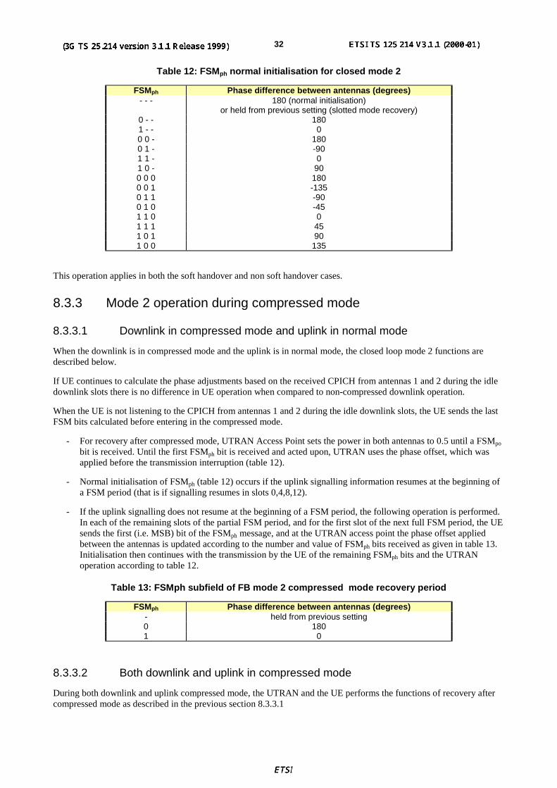
3GPP
3G TS 25.214 V3.1.1 (1999-12)323G TS 25.214 version 3.1.0
Table 12: FSMph normal initialisation for closed mode 2
FSMph Phase difference between antennas (degrees)- - - 180 (normal initialisation)
or held from previous setting (slotted mode recovery)0 - - 1801 - - 00 0 - 1800 1 - -901 1 - 01 0 - 900 0 0 1800 0 1 -1350 1 1 -900 1 0 -451 1 0 01 1 1 451 0 1 901 0 0 135
This operation applies in both the soft handover and non soft handover cases.
8.3.3 Mode 2 operation during compressed mode
8.3.3.1 Downlink in compressed mode and uplink in normal mode
When the downlink is in compressed mode and the uplink is in normal mode, the closed loop mode 2 functions aredescribed below.
If UE continues to calculate the phase adjustments based on the received CPICH from antennas 1 and 2 during the idledownlink slots there is no difference in UE operation when compared to non-compressed downlink operation.
When the UE is not listening to the CPICH from antennas 1 and 2 during the idle downlink slots, the UE sends the lastFSM bits calculated before entering in the compressed mode.
- For recovery after compressed mode, UTRAN Access Point sets the power in both antennas to 0.5 until a FSMpo
bit is received. Until the first FSMph bit is received and acted upon, UTRAN uses the phase offset, which wasapplied before the transmission interruption (table 12).
- Normal initialisation of FSMph (table 12) occurs if the uplink signalling information resumes at the beginning ofa FSM period (that is if signalling resumes in slots 0,4,8,12).
- If the uplink signalling does not resume at the beginning of a FSM period, the following operation is performed.In each of the remaining slots of the partial FSM period, and for the first slot of the next full FSM period, the UEsends the first (i.e. MSB) bit of the FSMph message, and at the UTRAN access point the phase offset appliedbetween the antennas is updated according to the number and value of FSMph bits received as given in table 13.Initialisation then continues with the transmission by the UE of the remaining FSMph bits and the UTRANoperation according to table 12.
Table 13: FSMph subfield of FB mode 2 compressed mode recovery period
FSMph Phase difference between antennas (degrees)- held from previous setting0 1801 0
8.3.3.2 Both downlink and uplink in compressed mode
During both downlink and uplink compressed mode, the UTRAN and the UE performs the functions of recovery aftercompressed mode as described in the previous section 8.3.3.1

3GPP
3G TS 25.214 V3.1.1 (1999-12)333G TS 25.214 version 3.1.0
9 Uplink synchronous transmission
9.1 General<Note: This scheme is not a base-line implementation capability.>
UplinkSynchronous Transmission Scheme(USTS) is an alternative technology applicable for low mobility terminals.USTS can reduce uplink intra-cell interference by means of making a cell receive orthogonalized signals from UEs. Toorthogonalize receiving signals from UEs,
- the same scrambling code is allocated to all dedicated physical channels in a cell,
- different channelization codes are allocated to all dedicated physical channels across all UEs in a cell and thespreading factor and code number of channelization code are delivered from network to each UE
- the channelization codes for DPDCH and DPCCH in a UE are chosen from either upper half part or the lowerhalf part of the OVSF code tree in a UE to reduce peak to average power ratio,
- additional scrambling codes can be allocated if all channelization codes are occupied, and
- the signal transmission time of each UE is adjusted.
The spreading and modulation scheme for USTS is same as section 4 of TS 25.213. In case of USTS, the longscrambling code described in section 4.3.2.2. of TS 25.213 is used. However, this long scrambling code is not UEspecific, but cell specific. In order to generate the cell specific long scrambling code, the initial loading value of PNgenerator is determined by the network
The channelization codes are Orthogonal Variable Spreading Factor (OVSF) codes that preserve the orthogonalitybetween USTS uplink channels of different rates and spreading factors.
The transmission time control is carried out by two steps. The first step is initial synchronization and the second istracking.
1) Initial synchronization: Adjust transmission time through the initial timing control message over FACH
2) Tracking Process (Closed Loop Timing control): Adjust the transmission time through the Time Alignment Bit(TAB) over DPCCH.
9.2 Initial synchronisation- When the cellreceives signal from UE over RACH, cell measures the difference in time between the received
timing and the reference time in the unit of 1/8 chip duration..
- The message for initial synchronization, which contains the difference in time, is delivered to UE via FACH.
- UE adjust its transmission time according to the message.
9.3 Tracking process- Cell periodically compares the reference time with received signal timing from UE.
- When the received timing is earlier than the reference time, Time Alignment Bit (TAB) = "0". When this is laterthan the reference time, TAB = "1".
- TAB replaces the TPC bit every timing control period of 20 msecand the last TPC bit of every two frames isreplaced by TAB.
- At the UE, hard decision on the TAB shall be performed, and when it is judged as "0", the transmission timeshall be delayed by 1/8 chip, whereas if it is judged as "1", the transmission time shall be advanced by 1/8 chip.

3GPP
3G TS 25.214 V3.1.1 (1999-12)343G TS 25.214 version 3.1.0
10 Idle Periods for IPDL Location method.To support time difference measurements that need to be made for location services there needs to be Idle Periodscreated in the DownLink (IPDL) during which time all channels from a node B are temporally seized. During these IdlePeriods the visibility of neighbour basestations from the UE is improved thus allowing the measurements to beperformed.
The Idle Periods are arranged in a predetermined pseudo random fashion according to higher layer parameters, theseparameters are used by layer 1 to arrange and use these Idle Periods. Idle Periods differ from compressed mode in thatthey are shorter in duration, all channels are silent simultaneously, and no attempt is made to prevent data loss.
In general there are two modes for these Idle Periods:
- Continuous mode, and
- Burst mode
In continuous mode the Idle Periods are active all the time. In burst mode the Idle Periods are arranged in bursts whereeach burst contains enough Idle Periods to allow a UE to make sufficient measurements for its location to be calculated.The bursts are separated by a period where no Idle Periods occur.
10.1 Parameters of IPDLThe follow parameters are signalled to the UE via higher layers:
IP_Status: This is a logic value that indicates if the Idle Periods are arranged in continuous or burst mode.
IP_Spacing: The number of 10ms frames between the start of a frame that contains an Idle Period and the nextframe that contains an Idle Period. (Note that there is at most one Idle Period in a frame)
IP_Length: The length of the Idle Periods, expressed in symbols of the CPICH.
IP_offset: A cell specific offset (can be used to synchronise Idle Periods from different sectors within a node B).
Seed: A seed for a pseudo random number generator.
Additionally in the case of burst mode operation the following parameters are also communicated to the UE.
Burst_Start: The SFN where the first burst of Idle Periods starts.
Burst_Length: The number of Idle Periods in a burst of Idle Periods.
Burst_Freq: The number of frames of the primary CPICH between the start of a burst and the start of the nextburst.
10.2 Calculation of Idle Period PositionThe position of the xth Idle Period relative to the start of a burst, expressed in symbols of the CPICH, is given by theformula (assuming the Idle Periods are indexed from 1, i.e. the first Idle Period is x=1 etc):
Seedrand
andnrandnrand
LengthIPdevMaxwhere
offsetIPdevMaxxrandSpacingIPx
=+−=
−=++
)0(
,6075mod)1283)1(*106()(
,_150_:
__mod)64mod(150*_*
Continuous mode can be considered as a specific case of the burst mode with just one burst spanning the whole SFNcycle. Note also that x will be reset to x=1 for the first idle period in a SFN cycle for both continuous and burst modesand will also, in the case of burst mode, be reset for the first Idle Period in every burst.
Figure 10.1 below illustrates the Idle Periods for the Burst Mode case.
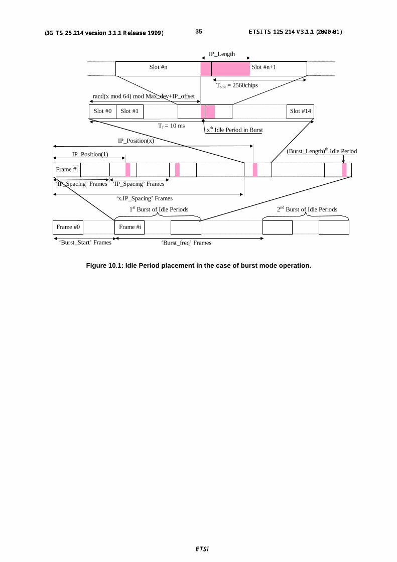
3GPP
3G TS 25.214 V3.1.1 (1999-12)353G TS 25.214 version 3.1.0
Slot #n+1Slot #n
(Burst_Length)th Idle Period
Tslot = 2560chips
IP_Length
‘x.IP_Spacing’ Frames
IP_Position(x)
IP_Position(1)
xth Idle Period in Burst
rand(x mod 64) mod Max_dev+IP_offset
‘Burst_freq’ Frames
1st Burst of Idle Periods
Frame #i
Frame #0
‘IP_Spacing’ Frames
‘Burst_Start’ Frames
Frame #i
2nd Burst of Idle Periods
‘IP_Spacing’ Frames
Slot #0 Slot #1 Slot #14
Tf = 10 ms
Figure 10.1: Idle Period placement in the case of burst mode operation.
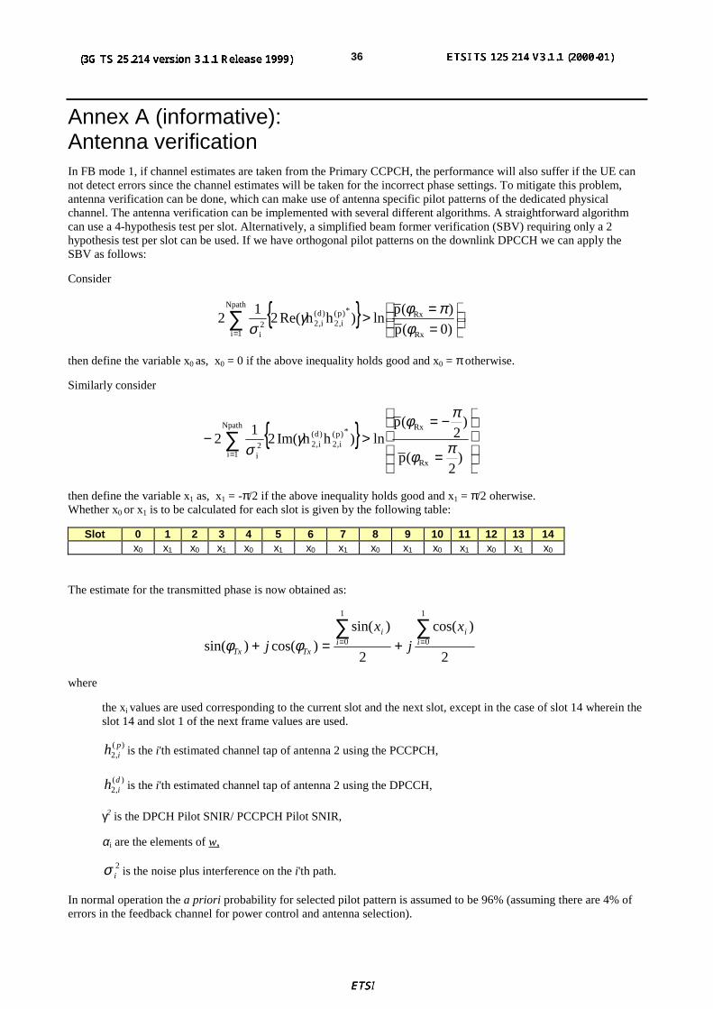
3GPP
3G TS 25.214 V3.1.1 (1999-12)363G TS 25.214 version 3.1.0
Annex A (informative):Antenna verificationIn FB mode 1, if channel estimates are taken from the Primary CCPCH, the performance will also suffer if the UE cannot detect errors since the channel estimates will be taken for the incorrect phase settings. To mitigate this problem,antenna verification can be done, which can make use of antenna specific pilot patterns of the dedicated physicalchannel. The antenna verification can be implemented with several different algorithms. A straightforward algorithmcan use a 4-hypothesis test per slot. Alternatively, a simplified beam former verification (SBV) requiring only a 2hypothesis test per slot can be used. If we have orthogonal pilot patterns on the downlink DPCCH we can apply theSBV as follows:
Consider
{ }
==>∑
= )0(p
)(pln)hhRe(2
12
Rx
Rx*)p(i,2
)d(i,2
Npath
1i2i φ
πφγσ
then define the variable x0 as, x0 = 0 if the above inequality holds good and x0 = π otherwise.
Similarly consider
{ }
=
−=>− ∑
= )2
(p
)2
(pln)hhIm(2
12
Rx
Rx*)p(i,2
)d(i,2
Npath
1i2i
πφ
πφγ
σ
then define the variable x1 as, x1 = -π/2 if the above inequality holds good and x1 = π/2 oherwise.Whether x0 or x1 is to be calculated for each slot is given by the following table:
Slot 0 1 2 3 4 5 6 7 8 9 10 11 12 13 14x0 x1 x0 x1 x0 x1 x0 x1 x0 x1 x0 x1 x0 x1 x0
The estimate for the transmitted phase is now obtained as:
2
)cos(
2
)sin()cos()sin(
1
0
1
0∑∑== +=+ i
ii
i
TxTx
xj
xj φφ
where
the xi values are used corresponding to the current slot and the next slot, except in the case of slot 14 wherein theslot 14 and slot 1 of the next frame values are used.
)(,2pih is the i'th estimated channel tap of antenna 2 using the PCCPCH,
)(,2dih is the i'th estimated channel tap of antenna 2 using the DPCCH,
γ2 is the DPCH Pilot SNIR/ PCCPCH Pilot SNIR,
αi are the elements of w,
2iσ is the noise plus interference on the i'th path.
In normal operation the a priori probability for selected pilot pattern is assumed to be 96% (assuming there are 4% oferrors in the feedback channel for power control and antenna selection).

3GPP
3G TS 25.214 V3.1.1 (1999-12)373G TS 25.214 version 3.1.0
Annex B (Informative):Power control timingThe power control timing described in this annex should be seen as an example on how the control bits have to beplaced in order to permit a short TPC delay.
In order to maximise the cell radius distance within which one-slot control delay is achieved, the frame timing of anuplink DPCH is delayed by 1024 chips from that of the corresponding downlink DPCH measured at the UE antenna.
Responding to a downlink TPC command, the UE shall change its uplink DPCH output power at the beginning of thefirst uplink pilot field after the TPC command reception. Responding to an uplink TPC command, the UTRAN accesspoint shall change its DPCH output power at the beginning of the next downlink pilot field after the reception of thewhole TPC command. Note that in soft handover, the TPC command is sent over one slot when DPC_MODE is 0 andover three slots when DPC_MODE is 1. Note also that the delay from the uplink TPC command reception to the powerchange timing is not specified forUTRAN. The UE shall decide and send TPC commands on the uplink based on thedownlink SIR measurement. The TPC command field on the uplink starts, when measured at the UE antenna, 512chips after the end of the downlink pilot field. The UTRAN access point shall decide and send TPC commands basedon the uplink SIR measurement. However, the SIR measurement periods are not specified either for UE nor UTRAN.
Figure B-1 illustrates an example of transmitter power control timings.
Data2Data1
1,2 The SIR measurement periods illustrated here are examples. Other ways of measurement are allowed to achieve accurate SIR estimation.3 If there is not enough time for UTRAN to respond to the TPC, the action can be delayed until the next slot.
Data1TPC
Data1TPC
PILOTPILOT
PILOT
ResponseTo TPC (*3)
TPC
DL SIRmeasurement (*1)
PILOT TFCI TPC
DL-UL timing offset (1024 chips)
Slot (2560 chips)
PILOTPILOT Data2Data1TPC
PILOTPILOT TFCI TPC
Slot (2560 chips)
Propagation delay
UL SIRmeasurement (*2)
Responseto TPC
DL DPCCHat UTRAN
Propagation delay
DL DPCCHat UE
UL DPCCHat UTRAN
UL DPCCHat UE
512 chips
TFCI
TFCI
Figure B-1: Transmitter power control timing
3GPP
3G TS 25.214 V3.1.1 (1999-12)383G TS 25.214 version 3.1.0
Annex C (Informative):Cell search procedureDuring the cell search, the UE searches for a cell and determines the downlink scrambling code and framesynchronisation of that cell. The cell search is typically carried out in three steps:
Step 1: Slot synchronisation
During the first step of the cell search procedure the UE uses the SCH’s primary synchronisation code to acquire slotsynchronisation to a cell. This is typically done with a single matched filter (or any similar device) matched to theprimary synchronisation code which is common to all cells. The slot timing of the cell can be obtained by detectingpeaks in the matched filter output.
Step 2: Frame synchronisation and code-group identification
During the second step of the cell search procedure, the UE uses the SCH’s secondary synchronisation code to findframe synchronisation and identify the code group of the cell found in the first step. This is done by correlating thereceived signal with all possible secondary synchronisation code sequences, and identifying the maximum correlationvalue. Since the cyclic shifts of the sequences are unique the code group as well as the frame synchronisation isdetermined.
Step 3: Scrambling-code identification
During the third and last step of the cell search procedure, the UE determines the exact primary scrambling code usedby the found cell. The primary scrambling code is typically identified through symbol-by-symbol correlation over theCPICH with all codes within the code group identified in the second step. After the primary scrambling code has beenidentified, the Primary CCPCH can be detected.And the system- and cell specific BCH information can be read.
If the UE has received information about which scrambling codes to search for, steps 2 and 3 above can be simplified.

3GPP
3G TS 25.214 V3.1.1 (1999-12)393G TS 25.214 version 3.1.0
Annex D (informative):Change history
Change historyTSG RAN# Version CR Tdoc RAN New Version Subject/CommentRAN_05 - - RP-99531 3.0.0 Approved at TSG RAN #5 and placed under Change Control
RAN_06 3.0.0 003 RP-99686 3.1.0 Flexible timing of UTRAN response to uplink closed loop Txdiversity feedback commands
RAN_06 3.0.0 006 RP-99686 3.1.0 CPCH power control preamble lengthRAN_06 3.0.0 007 RP-99686 3.1.0 Removal of open loop power controlRAN_06 3.0.0 008 RP-99687 3.1.0 Power offset of AICH and PICHRAN_06 3.0.0 009 RP-99686 3.1.0 Update of Random Access ProcedureRAN_06 3.0.0 010 RP-99686 3.1.0 oft symbol combining for uplink power control
RAN_06 3.0.0 011 RP-99685 3.1.0Clarification of closed loop transmit diversity figure in section 8 andclosed loop operation in compressed mode for mode 2 in section8.3 of TS 25.214
RAN_06 3.0.0 012 RP-99686 3.1.0 Uplink power control maximum TX powerRAN_06 3.0.0 013 RP-99686 3.1.0 Setting of beta values for multi-codeRAN_06 3.0.0 014 RP-99686 3.1.0 Consolidation of CPCH Power Control Preamble InformationRAN_06 3.0.0 015 RP-99686 3.1.0 Consolidation of Power Control Information for DCH InitialisationRAN_06 3.0.0 016 RP-99686 3.1.0 Uplink power control in compressed modeRAN_06 3.0.0 018 RP-99686 3.1.0 Timing for initialisation proceduresRAN_06 3.0.0 021 RP-99687 3.1.0 20 ms RACH message lengthRAN_06 3.0.0 023 RP-99684 3.1.0 Maximum Tx Power at uplink compressed ModeRAN_06 3.0.0 024 RP-99687 3.1.0 Setting of power in uplink compressed modeRAN_06 3.0.0 025 RP-99687 3.1.0 Cleanup of synchronisation proceduresRAN_06 3.0.0 026 RP-99686 3.1.0 Downlink power controlRAN_06 3.0.0 029 RP-99687 3.1.0 Out-of-synch handlingRAN_06 3.0.0 030 RP-99687 3.1.0 State update rule addition to SSDT specificationRAN_06 3.0.0 033 RP-99687 3.1.0 Uplink TX timing adjustmentRAN_06 3.0.0 036 RP-99687 3.1.0 Inclusion of idle periods for the IPDL LCSRAN_06 3.0.0 041 RP-99686 3.1.0 Revision of power control timing textRAN_06 3.0.0 042 RP-99687 3.1.0 Inclusion of adjustment loop in downlink power control- 3.1.0 - - 3.1.1 Change history was added by the editor

40
ETSI
ETSI TS 125 214 V3.1.1 (2000-01)(3G TS 25.214 version 3.1.1 Release 1999)
History
Document history
V3.1.1 January 2000 Publication


![its-wiki.noUM TS security will improve on the security of 2G systems U TMS security will offer new security features [services] Threat/risk analysis for 3G systems performed 3G TS](https://img.dokumen.tips/doc/110x75/5ea22dceab998533553e7e29/its-wikino-um-ts-security-will-improve-on-the-security-of-2g-systems-u-tms-security.jpg)


![3G TS 25.433 V1.0 - 株式会社QT · PDF file3GPP [UMTS ] 4 3G TS 25.433 V1.0 ... 9.1.4 Radio Link Setup Failure ... TFCI Transport Format Combination Indicator TFCS Transport Format](https://img.dokumen.tips/doc/110x75/5a707a147f8b9aa2538c1791/3g-ts-25433-v10-qtwwwqtcjp3gppspecs25433-102pdfpdf.jpg)


