Embed Size (px)
Citation preview

7/16/2019 QDX 6000 System Administrator Guide
http://slidepdf.com/reader/full/qdx-6000-system-administrator-guide 1/126
4.0.0 | Nov. 2011 | 3725-30856-001/A
Polycom®
QDX™
6000 System Administrator Guide

7/16/2019 QDX 6000 System Administrator Guide
http://slidepdf.com/reader/full/qdx-6000-system-administrator-guide 2/126
©2011 Polycom, Inc. All rights reserved.
Polycom, Inc.4750 Willow RoadPleasanton, CA 94588-2708USA
No part of this document may be reproduced or transmitted in any form or by any means, electronic or
mechanical, for any purpose, without the express written permission of Polycom, Inc. Under the law,reproducing includes translating into another language or format.
As between the parties, Polycom, Inc., retains title to and ownership of all proprietary rights with respect to thesoftware contained within its products. The software is protected by United States copyright laws andinternational treaty provision. Therefore, you must treat the software like any other copyrighted material (e.g.,a book or sound recording).
Every effort has been made to ensure that the information in this manual is accurate. Polycom, Inc., is not responsible for printing or clerical errors. Information in this document is subject to change without notice.
Trademark Information
Polycom®, the Polycom “Triangles” logo, and the names and marks associated with Polycom’s products aretrademarks and/or service marks of Polycom, Inc., and are registered and/or common-law marks in the UnitedStates and various other countries.
All other trademarks are the property of their respective owners.
Patent Information
The accompanying product is protected by one or more U.S. and foreign patents and/or pending patent applications held by Polycom, Inc.

7/16/2019 QDX 6000 System Administrator Guide
http://slidepdf.com/reader/full/qdx-6000-system-administrator-guide 3/126
iii
About This Guide
The Administrator Guide for Polycom QDX 6000 Systems is for administratorswho need to configure, customize, manage, and troubleshoot Polycom QDX6000 systems.
Please read the Polycom QDX 6000 system documentation before you installor operate the system. The following related documents for Polycom QDX6000 systems are available at www.polycom.com/videodocumentation:
• Hardware Installation Guide for Polycom QDX Systems, which describes howto set up the hardware
• User Guide for Polycom QDX 6000 Systems, which describes how to performvideo conferencing tasks
• Release Notes, which provides brief information of the release version
• API Reference Manual for Polycom QDX 6000 Systems, which provides APIcommand descriptions
For support or service, please contact your Polycom distributor or go toPolycom Support at www.polycom.com/support.

7/16/2019 QDX 6000 System Administrator Guide
http://slidepdf.com/reader/full/qdx-6000-system-administrator-guide 4/126
Administrator Guide for Polycom QDX 6000 System
iv

7/16/2019 QDX 6000 System Administrator Guide
http://slidepdf.com/reader/full/qdx-6000-system-administrator-guide 5/126
Contents
v
Contents
1 Introducing the Polycom QDX 6000 Systems . . . . . . . . . . . 1-1Polycom QDX 6000 Systems . . . . . . . . . . . . . . . . . . . . . . . . . . . . . . . . . . . . . . . . . . . . . . . . . . . . . 1-1
Setting Up Your System Hardware . . . . . . . . . . . . . . . . . . . . . . . . . . . . . . . . . . . . . . . . . . . . . . . 1-1
Positioning the System . . . . . . . . . . . . . . . . . . . . . . . . . . . . . . . . . . . . . . . . . . . . . . . . . . . . . . . . . . 1-2
Positioning the Polycom QDX 6000 Systems . . . . . . . . . . . . . . . . . . . . . . . . . . . . . . . . . . . 1-2
Powering On and Off . . . . . . . . . . . . . . . . . . . . . . . . . . . . . . . . . . . . . . . . . . . . . . . . . . . . . . . . . . . 1-3
Powering On the Polycom QDX 6000 Systems . . . . . . . . . . . . . . . . . . . . . . . . . . . . . . . . . 1-3
Configuring the Polycom QDX 6000 System . . . . . . . . . . . . . . . . . . . . . . . . . . . . . . . . . . . . . . . 1-4
Setup Wizard . . . . . . . . . . . . . . . . . . . . . . . . . . . . . . . . . . . . . . . . . . . . . . . . . . . . . . . . . . . . . . 1-4
Admin Settings . . . . . . . . . . . . . . . . . . . . . . . . . . . . . . . . . . . . . . . . . . . . . . . . . . . . . . . . . . . . 1-4
2 Networks . . . . . . . . . . . . . . . . . . . . . . . . . . . . . . . . . . . . . 2-1Getting the Network Ready . . . . . . . . . . . . . . . . . . . . . . . . . . . . . . . . . . . . . . . . . . . . . . . . . . . . . 2-1
Connecting to the LAN . . . . . . . . . . . . . . . . . . . . . . . . . . . . . . . . . . . . . . . . . . . . . . . . . . . . . . . . . 2-1
Configuring LAN Properties . . . . . . . . . . . . . . . . . . . . . . . . . . . . . . . . . . . . . . . . . . . . . . . . . 2-1
Configuring IP Settings . . . . . . . . . . . . . . . . . . . . . . . . . . . . . . . . . . . . . . . . . . . . . . . . . . . . . 2-5Specifying H.323 Settings . . . . . . . . . . . . . . . . . . . . . . . . . . . . . . . . . . . . . . . . . . . . . . . 2-5Configuring the System to Use a Gatekeeper . . . . . . . . . . . . . . . . . . . . . . . . . . . . . . . 2-6Configuring the System to Use a Gateway . . . . . . . . . . . . . . . . . . . . . . . . . . . . . . . . . 2-7
Specifying SIP Settings . . . . . . . . . . . . . . . . . . . . . . . . . . . . . . . . . . . . . . . . . . . . . . . . . . . . . . 2-8
Specifying Quality of Service . . . . . . . . . . . . . . . . . . . . . . . . . . . . . . . . . . . . . . . . . . . . . . . . 2-9Configuring the System for Use with a Firewall or NAT . . . . . . . . . . . . . . . . . . . . . . . . 2-10
Firewall Settings . . . . . . . . . . . . . . . . . . . . . . . . . . . . . . . . . . . . . . . . . . . . . . . . . . . . . . 2-10H.460 NAT Firewall Traversal . . . . . . . . . . . . . . . . . . . . . . . . . . . . . . . . . . . . . . . . . . 2-12
Configuring Call Preferences . . . . . . . . . . . . . . . . . . . . . . . . . . . . . . . . . . . . . . . . . . . . . . . . . . . 2-13
Configuring Dialing Order Settings . . . . . . . . . . . . . . . . . . . . . . . . . . . . . . . . . . . . . . . . . . . . . . 2-14
3 Monitors and Cameras . . . . . . . . . . . . . . . . . . . . . . . . . . . 3-1Connecting Monitors . . . . . . . . . . . . . . . . . . . . . . . . . . . . . . . . . . . . . . . . . . . . . . . . . . . . . . . . . . . 3-1
Configuring Monitor Settings . . . . . . . . . . . . . . . . . . . . . . . . . . . . . . . . . . . . . . . . . . . . . . . . . . . . 3-2
Adjusting Screen Layout . . . . . . . . . . . . . . . . . . . . . . . . . . . . . . . . . . . . . . . . . . . . . . . . . . . . 3-4Specifying, Showing and Turning Off the PIP . . . . . . . . . . . . . . . . . . . . . . . . . . . . . . 3-4
Adjusting the Monitor’s Color Balance, Sharpness, and Brightness . . . . . . . . . . . . . . . . 3-5
Preventing Monitor Burn-In . . . . . . . . . . . . . . . . . . . . . . . . . . . . . . . . . . . . . . . . . . . . . . . . . 3-6
Connecting Cameras . . . . . . . . . . . . . . . . . . . . . . . . . . . . . . . . . . . . . . . . . . . . . . . . . . . . . . . . . . . 3-7
Connecting Cameras to Polycom QDX 6000 Systems . . . . . . . . . . . . . . . . . . . . . . . . . . . . 3-7
Configuring Camera Settings and Video Quality Options . . . . . . . . . . . . . . . . . . . . . . . . . . . . 3-8
Configuring Advanced Polycom EagleEye SD Camera Settings . . . . . . . . . . . . . . . . . . . . . 3-11
Configuring Camera Presets . . . . . . . . . . . . . . . . . . . . . . . . . . . . . . . . . . . . . . . . . . . . . . . . . . . . 3-13

7/16/2019 QDX 6000 System Administrator Guide
http://slidepdf.com/reader/full/qdx-6000-system-administrator-guide 6/126
Administrator Guide Polycom QDX 6000 Systems
vi
4 Microphones and Speakers . . . . . . . . . . . . . . . . . . . . . . . . 4-1Connecting Audio Input . . . . . . . . . . . . . . . . . . . . . . . . . . . . . . . . . . . . . . . . . . . . . . . . . . . . . . . . 4-1
Connecting Audio Input to Polycom QDX 6000 Systems . . . . . . . . . . . . . . . . . . . . . . . . . 4-1
Connecting Devices to the Polycom QDX 6000 Microphone Input . . . . . . . . . . . . . . . . 4-1
Polycom Microphone Lights . . . . . . . . . . . . . . . . . . . . . . . . . . . . . . . . . . . . . . . . . . . . . . . . . 4-2
Connecting Audio Output . . . . . . . . . . . . . . . . . . . . . . . . . . . . . . . . . . . . . . . . . . . . . . . . . . . . . . . 4-2
Connecting Speakers to Polycom QDX 6000 Systems . . . . . . . . . . . . . . . . . . . . . . . . . . . . 4-2
Setting the Speaker Volume . . . . . . . . . . . . . . . . . . . . . . . . . . . . . . . . . . . . . . . . . . . . . . . . . 4-3
Configuring Audio Settings . . . . . . . . . . . . . . . . . . . . . . . . . . . . . . . . . . . . . . . . . . . . . . . . . . . . . 4-3
General Audio Settings . . . . . . . . . . . . . . . . . . . . . . . . . . . . . . . . . . . . . . . . . . . . . . . . . . . . . 4-3
StereoSurround Settings . . . . . . . . . . . . . . . . . . . . . . . . . . . . . . . . . . . . . . . . . . . . . . . . . . . . 4-5
Audio Meters . . . . . . . . . . . . . . . . . . . . . . . . . . . . . . . . . . . . . . . . . . . . . . . . . . . . . . . . . . . . . . 4-6
Testing StereoSurround . . . . . . . . . . . . . . . . . . . . . . . . . . . . . . . . . . . . . . . . . . . . . . . . . . . . . 4-6
5 Content and Captions . . . . . . . . . . . . . . . . . . . . . . . . . . . . 5-1Connecting VCR/DVDs . . . . . . . . . . . . . . . . . . . . . . . . . . . . . . . . . . . . . . . . . . . . . . . . . . . . . . . . 5-1
Configuring VCR/DVD Player Settings . . . . . . . . . . . . . . . . . . . . . . . . . . . . . . . . . . . . . . . . . . . 5-1
Playing a Videotape or DVD . . . . . . . . . . . . . . . . . . . . . . . . . . . . . . . . . . . . . . . . . . . . . . . . 5-1
Connecting Computers to Polycom QDX 6000 Systems . . . . . . . . . . . . . . . . . . . . . . . . . . . . . . 5-2
Configuring Content Sharing . . . . . . . . . . . . . . . . . . . . . . . . . . . . . . . . . . . . . . . . . . . . . . . . . . . . 5-2
Configuring Content Display with People+Content IP . . . . . . . . . . . . . . . . . . . . . . . . . . . . . . 5-3
Configuring Captioning . . . . . . . . . . . . . . . . . . . . . . . . . . . . . . . . . . . . . . . . . . . . . . . . . . . . . . . . . 5-3
Configuring Meeting Captions . . . . . . . . . . . . . . . . . . . . . . . . . . . . . . . . . . . . . . . . . . . . . . . 5-4
Configuring Rolling Captions . . . . . . . . . . . . . . . . . . . . . . . . . . . . . . . . . . . . . . . . . . . . . . . . 5-4
6 Calling and Answering . . . . . . . . . . . . . . . . . . . . . . . . . . . 6-1Configuring Call Settings . . . . . . . . . . . . . . . . . . . . . . . . . . . . . . . . . . . . . . . . . . . . . . . . . . . . . . . 6-1
Setting the Call Answering Mode . . . . . . . . . . . . . . . . . . . . . . . . . . . . . . . . . . . . . . . . . . . . . . . . 6-2
Configuring Directory Settings . . . . . . . . . . . . . . . . . . . . . . . . . . . . . . . . . . . . . . . . . . . . . . . . . . . 6-3
Creating a Localized System Name with the Polycom QDX 6000 Web Interface . . . . . 6-3
Managing Directories with the Polycom QDX 6000 Web Interface . . . . . . . . . . . . . . . . 6-4
Configuring the Global Directory . . . . . . . . . . . . . . . . . . . . . . . . . . . . . . . . . . . . . . . . . . . . . . . . 6-5
Directory Groups . . . . . . . . . . . . . . . . . . . . . . . . . . . . . . . . . . . . . . . . . . . . . . . . . . . . . . . . . . . . . . 6-7
Global Directory Groups . . . . . . . . . . . . . . . . . . . . . . . . . . . . . . . . . . . . . . . . . . . . . . . . . . . . 6-7
Local Directory Groups . . . . . . . . . . . . . . . . . . . . . . . . . . . . . . . . . . . . . . . . . . . . . . . . . . . . . 6-8
7 System Location, Appearance, and Tones . . . . . . . . . . . . . . 7-1Configuring Regional Settings . . . . . . . . . . . . . . . . . . . . . . . . . . . . . . . . . . . . . . . . . . . . . . . . . . . 7-1Customizing the Home Screen . . . . . . . . . . . . . . . . . . . . . . . . . . . . . . . . . . . . . . . . . . . . . . . . . . . 7-3
Displaying Contacts and Speed Dial Sites . . . . . . . . . . . . . . . . . . . . . . . . . . . . . . . . . . . . . 7-5
Adding Marquee Text . . . . . . . . . . . . . . . . . . . . . . . . . . . . . . . . . . . . . . . . . . . . . . . . . . . . . . 7-6
Setting Ring Tones and Alert Tones . . . . . . . . . . . . . . . . . . . . . . . . . . . . . . . . . . . . . . . . . . . . . . . 7-7
Customizing Camera Names and Icons . . . . . . . . . . . . . . . . . . . . . . . . . . . . . . . . . . . . . . . . . . . 7-7
Screen Savers . . . . . . . . . . . . . . . . . . . . . . . . . . . . . . . . . . . . . . . . . . . . . . . . . . . . . . . . . . . . . . . . . . 7-7

7/16/2019 QDX 6000 System Administrator Guide
http://slidepdf.com/reader/full/qdx-6000-system-administrator-guide 7/126
Contents
vii
Adding Screen Saver Text . . . . . . . . . . . . . . . . . . . . . . . . . . . . . . . . . . . . . . . . . . . . . . . . . . . 7-7
Customizing System Logos . . . . . . . . . . . . . . . . . . . . . . . . . . . . . . . . . . . . . . . . . . . . . . . . . . . . . . 7-8
Adding a Screen Saver Logo . . . . . . . . . . . . . . . . . . . . . . . . . . . . . . . . . . . . . . . . . . . . . . . . . 7-8
Adding a Web Welcome Logo . . . . . . . . . . . . . . . . . . . . . . . . . . . . . . . . . . . . . . . . . . . . . . . 7-9
Adding a Splash Logo . . . . . . . . . . . . . . . . . . . . . . . . . . . . . . . . . . . . . . . . . . . . . . . . . . . . . . 7-9Adding an Embedded UI Logo . . . . . . . . . . . . . . . . . . . . . . . . . . . . . . . . . . . . . . . . . . . . . . 7-9
Adding a Web Header Logo . . . . . . . . . . . . . . . . . . . . . . . . . . . . . . . . . . . . . . . . . . . . . . . . 7-10
Restoring the Default Logos . . . . . . . . . . . . . . . . . . . . . . . . . . . . . . . . . . . . . . . . . . . . . . . . 7-10
8 Security . . . . . . . . . . . . . . . . . . . . . . . . . . . . . . . . . . . . . . 8-1Screens that Require a Password for Access . . . . . . . . . . . . . . . . . . . . . . . . . . . . . . . . . . . . . . . . 8-1
Configuring Security Options . . . . . . . . . . . . . . . . . . . . . . . . . . . . . . . . . . . . . . . . . . . . . . . . . . . . 8-2
Configuring Security Mode . . . . . . . . . . . . . . . . . . . . . . . . . . . . . . . . . . . . . . . . . . . . . . . . . . . . . . 8-4
Enabling a Security Profile . . . . . . . . . . . . . . . . . . . . . . . . . . . . . . . . . . . . . . . . . . . . . . . . . . 8-6
Enabling AES Encryption . . . . . . . . . . . . . . . . . . . . . . . . . . . . . . . . . . . . . . . . . . . . . . . . . . . . . . . 8-7
Setting Password Policies . . . . . . . . . . . . . . . . . . . . . . . . . . . . . . . . . . . . . . . . . . . . . . . . . . . . . . . 8-7Setting the Room and Remote Access Passwords . . . . . . . . . . . . . . . . . . . . . . . . . . . . . . . . . . . 8-8
Setting an Account Lockout . . . . . . . . . . . . . . . . . . . . . . . . . . . . . . . . . . . . . . . . . . . . . . . . . . . . 8-10
Managing User Access to Settings and Features . . . . . . . . . . . . . . . . . . . . . . . . . . . . . . . . . . . 8-10
9 Managing the System Remotely . . . . . . . . . . . . . . . . . . . . . 9-1Using the Polycom QDX 6000 Web Interface . . . . . . . . . . . . . . . . . . . . . . . . . . . . . . . . . . . . . . . 9-1
Accessing the Polycom QDX 6000 Web Interface . . . . . . . . . . . . . . . . . . . . . . . . . . . . . . . 9-1
Monitoring a Room or Call with the Polycom QDX 6000 Web Interface . . . . . . . . . . . . 9-2
Managing System Profiles with the Polycom QDX 6000 Web Interface . . . . . . . . . . . . 9-3
Sending a Message . . . . . . . . . . . . . . . . . . . . . . . . . . . . . . . . . . . . . . . . . . . . . . . . . . . . . . . . . 9-4
Setting Up SNMP . . . . . . . . . . . . . . . . . . . . . . . . . . . . . . . . . . . . . . . . . . . . . . . . . . . . . . . . . . 9-4Downloading MIBs . . . . . . . . . . . . . . . . . . . . . . . . . . . . . . . . . . . . . . . . . . . . . . . . . . . . . 9-4Configuring for SNMP Management . . . . . . . . . . . . . . . . . . . . . . . . . . . . . . . . . . . . . . 9-5
Keeping your Software Current . . . . . . . . . . . . . . . . . . . . . . . . . . . . . . . . . . . . . . . . . . . . . . . . . . 9-6
10 Control Devices . . . . . . . . . . . . . . . . . . . . . . . . . . . . . . . . 10-1Configuring Remote Control Behavior . . . . . . . . . . . . . . . . . . . . . . . . . . . . . . . . . . . . . . . . . . . 10-1
Configuring RS-232 Serial Port Settings . . . . . . . . . . . . . . . . . . . . . . . . . . . . . . . . . . . . . . . . . . 10-1
11 Statistics and Diagnostics . . . . . . . . . . . . . . . . . . . . . . . . . 11-1Diagnostic Screens . . . . . . . . . . . . . . . . . . . . . . . . . . . . . . . . . . . . . . . . . . . . . . . . . . . . . . . . . . . . 11-1
System Status . . . . . . . . . . . . . . . . . . . . . . . . . . . . . . . . . . . . . . . . . . . . . . . . . . . . . . . . . . . . . 11-2Server Status . . . . . . . . . . . . . . . . . . . . . . . . . . . . . . . . . . . . . . . . . . . . . . . . . . . . . . . . . . . . . 11-2
Call Statistics . . . . . . . . . . . . . . . . . . . . . . . . . . . . . . . . . . . . . . . . . . . . . . . . . . . . . . . . . . . . . 11-3
Network . . . . . . . . . . . . . . . . . . . . . . . . . . . . . . . . . . . . . . . . . . . . . . . . . . . . . . . . . . . . . . . . . 11-4
Video . . . . . . . . . . . . . . . . . . . . . . . . . . . . . . . . . . . . . . . . . . . . . . . . . . . . . . . . . . . . . . . . . . . . 11-4
Audio . . . . . . . . . . . . . . . . . . . . . . . . . . . . . . . . . . . . . . . . . . . . . . . . . . . . . . . . . . . . . . . . . . . 11-5
Reset or Restart System . . . . . . . . . . . . . . . . . . . . . . . . . . . . . . . . . . . . . . . . . . . . . . . . . . . . 11-6

7/16/2019 QDX 6000 System Administrator Guide
http://slidepdf.com/reader/full/qdx-6000-system-administrator-guide 8/126
Administrator Guide Polycom QDX 6000 Systems
viii
Recent Calls . . . . . . . . . . . . . . . . . . . . . . . . . . . . . . . . . . . . . . . . . . . . . . . . . . . . . . . . . . . . . . . . . . 11-6
Call Detail Report (CDR) . . . . . . . . . . . . . . . . . . . . . . . . . . . . . . . . . . . . . . . . . . . . . . . . . . . . . . . 11-7
Information in the CDR . . . . . . . . . . . . . . . . . . . . . . . . . . . . . . . . . . . . . . . . . . . . . . . . . . . . 11-7
Call Detail Report Archives . . . . . . . . . . . . . . . . . . . . . . . . . . . . . . . . . . . . . . . . . . . . . . . . . 11-9
System Logs . . . . . . . . . . . . . . . . . . . . . . . . . . . . . . . . . . . . . . . . . . . . . . . . . . . . . . . . . . . . . . . . . 11-10Downloading System Logs from the Polycom QDX 6000 Web Interface . . . . . . . . . 11-10
System Log Settings in the Polycom QDX 6000 Web Interface . . . . . . . . . . . . . . . . . . 11-11
12 Troubleshooting . . . . . . . . . . . . . . . . . . . . . . . . . . . . . . . 12-1Placing a Test Call . . . . . . . . . . . . . . . . . . . . . . . . . . . . . . . . . . . . . . . . . . . . . . . . . . . . . . . . . . . . . 12-1
Enabling Basic Mode . . . . . . . . . . . . . . . . . . . . . . . . . . . . . . . . . . . . . . . . . . . . . . . . . . . . . . . . . . 12-2
Using the Restore Button . . . . . . . . . . . . . . . . . . . . . . . . . . . . . . . . . . . . . . . . . . . . . . . . . . . . . . . 12-2
Factory Restore . . . . . . . . . . . . . . . . . . . . . . . . . . . . . . . . . . . . . . . . . . . . . . . . . . . . . . . . . . . 12-3
How to Contact Technical Support . . . . . . . . . . . . . . . . . . . . . . . . . . . . . . . . . . . . . . . . . . . . . . 12-3
Regulatory Notices . . . . . . . . . . . . . . . . . Regulatory Notices-1
A System Back Panel Views and Cables . . . . . . . . . . . . . . . . A-1Video Inputs and Outputs . . . . . . . . . . . . . . . . . . . . . . . . . . . . . . . . . . . . . . . . . . . . . . . . . . . . . . A-1
Audio Inputs and Outputs . . . . . . . . . . . . . . . . . . . . . . . . . . . . . . . . . . . . . . . . . . . . . . . . . . . . . A-2
Network/Power Inputs and Outputs . . . . . . . . . . . . . . . . . . . . . . . . . . . . . . . . . . . . . . . . . . . . A-2
System Cables . . . . . . . . . . . . . . . . . . . . . . . . . . . . . . . . . . . . . . . . . . . . . . . . . . . . . . . . . . . . . . . . A-3
B Port Usage . . . . . . . . . . . . . . . . . . . . . . . . . . . . . . . . . . . . B-1
C Installing Polycom QDX 6000 Software . . . . . . . . . . . . . . . C-1Collecting License Numbers and System Serial Numbers . . . . . . . . . . . . . . . . . . . . . . . . . . . . C-1
Obtaining Key Codes for Software Upgrades . . . . . . . . . . . . . . . . . . . . . . . . . . . . . . . . . . . . . . C-2
Downloading the Software . . . . . . . . . . . . . . . . . . . . . . . . . . . . . . . . . . . . . . . . . . . . . . . . . . . . . . C-2
Installing Software . . . . . . . . . . . . . . . . . . . . . . . . . . . . . . . . . . . . . . . . . . . . . . . . . . . . . . . . . . . . . C-3
Installing a Software Upgrade on a System . . . . . . . . . . . . . . . . . . . . . . . . . . . . . . . . . . . . C-3
Installing a Software Downgrade on a System from 4.0 to 3.x . . . . . . . . . . . . . . . . . . . . C-3

7/16/2019 QDX 6000 System Administrator Guide
http://slidepdf.com/reader/full/qdx-6000-system-administrator-guide 9/126
1 - 1
1
Introducing the Polycom QDX 6000Systems
Your Polycom QDX 6000 video conferencing system is a state-of-the-art visual
collaboration tool. With standard definition video and crystal-clear sound,Polycom QDX 6000 systems provide natural video conferencing interactionthrough the most advanced video communications technology.
Polycom QDX 6000 SystemsThe Polycom QDX 6000 system provides integrator-class connectors andsupports multiple video and audio sources. These solutions allow integratorsto create specialized, unique, and real-time video environments for theircustomers.
Setting Up Your System HardwareThis manual provides information to supplement the setup sheets providedwith your system and its optional components. A printed copy of the systemsetup sheet is provided with each Polycom QDX 6000 system. PDF versions ofthe system setup sheets are available atwww.polycom.com/videodocumentation.

7/16/2019 QDX 6000 System Administrator Guide
http://slidepdf.com/reader/full/qdx-6000-system-administrator-guide 10/126
Administrator Guide for Polycom QDX 6000 System
1 - 2
Positioning the System
Positioning the Polycom QDX 6000 SystemsPolycom QDX 6000 systems are designed to be placed on a tabletop or in anequipment rack.
To position the system:
1. Install the mounting brackets on the system if you need to mount it in anequipment rack, or install the self-adhesive feet if you will place thesystem on a table or shelf.
2. Place the system in the desired location. Position the system so that thecamera does not face toward a window or other source of bright light.Leave enough space to connect the cables easily. Place the camera anddisplay together so that people at your site face the camera when they arelooking at the display.

7/16/2019 QDX 6000 System Administrator Guide
http://slidepdf.com/reader/full/qdx-6000-system-administrator-guide 11/126
Introducing the Polycom QDX 6000 Systems
1 - 3
Powering On and OffConnect power and power on the system after you have connected all of theequipment that you will use with it. Make sure that the system is powered off
before you connect devices to it.
Powering On the Polycom QDX 6000 Systems
To power on the Polycom QDX 6000 systems:
Press the power switch on the back of the system.
The Polycom splash screen is displayed within about 1 minute.
To power off the Polycom QDX 6000 systems: Press the power switch on the back of the system.
The indicator light on the front of the Polycom QDX 6000 system provides thisinformation:
Indicator Light System Status
Off System is powered off.
Steady red light System is initializing.
Blinking red light System is updating software.
Steady green light System is in a call.
Blinking red light against steady greenlight
System received an IR signal while ina call.
Steady blue light System is awake, not in a call.
Blinking red light against steady blue light System received an IR signal whileawake and not in a call.
Blinking blue light (on 1 sec, off 1sec) System is asleep.

7/16/2019 QDX 6000 System Administrator Guide
http://slidepdf.com/reader/full/qdx-6000-system-administrator-guide 12/126
Administrator Guide for Polycom QDX 6000 System
1 - 4
Configuring the Polycom QDX 6000 System
Setup WizardWhen you power on your system for the first time, the setup wizard detectsthe system’s IP connections and leads you through the minimumconfiguration steps required to place a call.
The setup wizard allows you to set a room password, which allows you tolimit access to the Admin Settings. The default room password is the 16-digitsystem serial number from the System Information screen or the back of thesystem.
You can run the setup wizard or view the configuration screens in either ofthese two ways.
• In the room with the system — Use the remote control to navigate thescreens and enter information. You can use the number pad on the remotecontrol to enter text just like you can with a cell phone.
• From a remote location — Use a web browser to access the Polycom QDX
6000 Web Interface. For more information about using the web interface,refer to Accessing the Polycom QDX 6000 Web Interface on page 9-1.
The setup wizard is available during initial setup, after a system update withsystem settings not saved, or after a system reset with system settings deleted.
Admin Settings
After you run the setup wizard, you can view or change the system’sconfiguration by going to the Admin Settings in the system’s local interface orweb interface.
If you enable a security profile in the setup wizard, certain configuration
settings are set and controlled automatically.
Make sure you can recall the room password if you set one. If you forget thepassword, you will have to reset the system, delete the system files, and run the
setup wizard again in order to access the Admin Settings and reset the password.If Security Mode is enabled, the room password is required to access the ResetSystem screen. If you forget the room password while the system is in SecurityMode, refer to Using the Restore Button on page 12-2.

7/16/2019 QDX 6000 System Administrator Guide
http://slidepdf.com/reader/full/qdx-6000-system-administrator-guide 13/126
2 - 1
2
Networks
This chapter covers network types used worldwide. Please note that not allnetwork types are available in all countries.
Getting the Network Ready Before you begin configuring the network options, you must make sure yournetwork is ready for video conferencing.
To begin, refer to the Network Planning Worksheets for Video Conferencingdocument, available on the Polycom web site. This document containsinformation you need to prepare your network.
Connecting to the LANYou must connect the system to a LAN to:
• Make H.323 or SIP calls
• Use a Global Directory Server
• Register with a management system
• Access the web interface
• Use People+Content™ IP
Configuring LAN PropertiesIn IPv4/IPv6 hybrid networks, the system tries IPv6 first. If that fails, thesystem tries to place the call using the IPv4 address.

7/16/2019 QDX 6000 System Administrator Guide
http://slidepdf.com/reader/full/qdx-6000-system-administrator-guide 14/126
Administrator Guide for Polycom QDX 6000 System
2 - 2
To configure LAN properties:
1. Go to System > Admin Settings > LAN Properties.
2. Configure these settings on the LAN Properties screen:
Points to Note about IPv6-only Network Limitations:
• Do not configure a Polycom Global Directory Server address.
• Disable IP H.323 in the Call Preference menu.
• The Polycom Global Management System™, Polycom ReadiManager®
SE200, and Polycom CMA™ system will not be able to connect to the PolycomQDX 6000 system.
Setting Description
IP Address (IPv4) Specifies how the system obtains an IP address.• Obtain IP address automatical ly — Select if the
system gets an IP address from the DHCP server on theLAN.
• Enter IP address manual ly — Select if the IP addresswill not be assigned automatically.
Changing this setting causes the system to restart.
IP Address If the system obtains its IP address automatically, this areadisplays the IP address currently assigned to the system.
If you selected Enter IP Address Manually, enter the IPaddress here. Changing the IP address causes the systemto restart.
Subnet Mask Displays the subnet mask currently assigned to the system.
If the system does not automatically obtain a subnet mask,enter one here.
Changing this setting causes the system to restart.
Default Gateway
(IPv4)
Displays the gateway currently assigned to the system.
If the system does not automatically obtain a gateway IPaddress, enter one here.
Changing this setting causes the system to restart.

7/16/2019 QDX 6000 System Administrator Guide
http://slidepdf.com/reader/full/qdx-6000-system-administrator-guide 15/126
Networks
2 - 3
3. Select and configure these settings:
IP Address (IPv6) Specifies how the system obtains an IP address.
• Obtain IP address automatical ly — Select if the
system gets an IP address automatically. DHCP is notcurrently supported for IPv6. When you choose thissetting, the system uses Stateless AddressAutoconfiguration (SLAAC) to obtain a global address,unique local address (ULA), or site-local address usingrouter advertisements. The network router(s) also mustbe configured appropriately to provide the advertisementpackets.
• Enter IP address manual ly — Select if the IP addresswill not be assigned automatically.
Changing this setting causes the system to restart.
Link-Local Displays the IPv6 address used for local communicationwithin a subnet.
Site-Local Displays the IPv6 address used for communication withinthe site or organization.
Global Address Displays the IPv6 internet address.
Default Gateway
(IPv6)
Displays the gateway currently assigned to the system.
If the system does not automatically obtain a gateway IPaddress, enter one here.
Changing this setting causes the system to restart.
Setting Description
Setting Description
Host Name Indicates the system’s DNS name.
Changing this setting causes the system to restart.
Domain
Name
Displays the domain name currently assigned to the system.
If the system does not automatically obtain a domain name, enterone here.
DNS Servers Displays the DNS servers currently assigned to the system.
If the system does not automatically obtain a DNS server address,enter up to four DNS servers here.
• IPv6: You can specify IPv6 DNS server addresses for IP
addresses entered manually or obtained automatically (in thecase of a system on a hybrid network that obtains IPv4 DNSserver addresses via DHCPv4).
• IPv4: You can specify IPv4 DNS server addresses only whenthe IPv4 address is entered manually. When the IPv4 addressis obtained automatically, the DNS Server addresses are alsoobtained automatically.
Changing this setting causes the system to restart.

7/16/2019 QDX 6000 System Administrator Guide
http://slidepdf.com/reader/full/qdx-6000-system-administrator-guide 16/126
Administrator Guide for Polycom QDX 6000 System
2 - 4
4. Select and configure these settings:
LAN Speed Specify the LAN speed to use. Note that the speed you choosemust be supported by the switch.
Choose Auto to have the network switch negotiate the speedautomatically. Choosing Auto automatically sets Duplex Mode to
Auto. If you choose 10 Mbps, or100 Mbps you must set Duplex
Mode to Half orFull.
Note: Polycom does not support Auto for the Polycom QDX 6000system only or the switch only; the settings for both must be thesame.
Changing this setting causes the system to restart.
Duplex Mode Specify the duplex mode to use. Note that the Duplex mode youchoose must be supported by the switch.
Choose Auto to have the network switch negotiate the Duplexmode automatically. Choosing Auto automatically sets LAN
Speed to Auto .Note: Polycom does not support Auto for the Polycom QDX 6000system only or the switch only; the settings for both must be thesame.
Changing this setting causes the system to restart.
Setting Description
Setting Description
Enable
EAP/802.1X
Specifies whether EAP/802.1X network access is enabled.Polycom QDX 6000 systems support the followingauthentication protocols:
• EAP-MD5
• EAP-PEAPv0 (MSCHAPv2)
• EAP-TTLS
Identity Specifies the system’s identity used for 802.1X authentication. This setting is available only when EAP/802.1X is enabled.
Password Specifies the system’s password used for 802.1Xauthentication. This setting is available only when EAP/802.1Xis enabled.
Enable 802.1p/Q Specifies whether VLAN and link layer priorities are enabled.
VLAN ID Specifies the identification of the Virtual LAN.This setting isavailable only when 802.1p/Q is enabled. The value can beany number from 1 to 4094.
Video Priority Sets the link layer priority of video traffic on the LAN. Videotraffic is any RTP traffic consisting of video data and anyassociated RTCP traffic. This setting is available only when802.1p/Q is enabled. The value can be any number from 0 to7, although 6 and 7 are not recommended.

7/16/2019 QDX 6000 System Administrator Guide
http://slidepdf.com/reader/full/qdx-6000-system-administrator-guide 17/126
Networks
2 - 5
Configuring IP Settings
Specifying H.323 Settings
If your network uses a gatekeeper, the system can automatically register itsH.323 name and extension. This allows others to call the system by enteringthe H.323 name or extension instead of the IP address.
To specify H.323 settings:
1. Go to System > Admin Settings > Network > IP > H.323 Settings.
2. Configure these settings on the H.323 Settings screen:
Audio Priori ty Sets the priority of audio traffic on the LAN. Audio traffic is anyRTP traffic consisting of audio data and any associated RTCP
traffic. This setting is available only when 802.1p/Q is enabled. The value can be any number from 0 to 7, although 6 and 7are not recommended.
Control Priority Sets the priority of control traffic on the LAN. Control traffic isany traffic consisting of control information associated with acall:
• H.323—H.225.0 Call Signaling, H.225.0 RAS, H.245, FarEnd Camera Control
• SIP—SIP Signaling, Far End Camera Control, Binary FloorControl Protocol (BFCP)
This setting is available only when 802.1p/Q is enabled. Thevalue can be any number from 0 to 7, although 6 and 7 are notrecommended.
Setting Description
Setting Description
Display H.323
Extension
Allows users to enter H.323 extensions separately from thegateway ID on the Place a Call screen. If your system isregistered with a gatekeeper, this setting also displays yourH.323 extension on the home screen.
If you do not select this setting, users make gateway calls byentering the call information in this format:
gateway ID +##+extensionH.323 Name Specifies the name that gatekeepers and gateways use to
identify this system. You can make point-to-point calls usingH.323 names if both systems are registered to a gatekeeper.
The H.323 Name is the same as the System Name, unlessyou change it. Your organization’s dial plan may define thenames you can use.

7/16/2019 QDX 6000 System Administrator Guide
http://slidepdf.com/reader/full/qdx-6000-system-administrator-guide 18/126
Administrator Guide for Polycom QDX 6000 System
2 - 6
Configuring the System to Use a Gatekeeper
A gatekeeper is a “network administrator” that supervises network traffic andmanages functions such as bandwidth control and admission control. Thegatekeeper also handles address translation, which allows users to make callsusing static aliases instead of IP addresses that may change each day.
To configure the system to use a gatekeeper:
1. Go to System > Admin Settings > Network > IP > H.323 Settings.
2. Select and configure these settings on the Gatekeeper screen:
H.323 Extens ion
(E.164)
Lets users place point-to-point calls using the extension if bothsystems are registered with a gatekeeper, and specifies the
extension that gatekeepers and gateways use to identify thissystem.
Your organization’s dial plan may define the extensions youcan use.
Setting Description
Setting Description
Use Gatekeeper Specifies whether to use a gatekeeper. Gateways andgatekeepers are required for calls from IP to ISDN.
• Off — Calls do not use a gatekeeper.
• Auto — System attempts to automatically find anavailable gatekeeper.
• Specify — Calls use the specified gatekeeper. Enter thegatekeeper’s IP address or name (for example,gatekeeper.companyname.usa.com, or 10.11.12.13).
H.323 Name Specifies the name that gatekeepers use to identify thissystem. You can make point-to-point calls using H.323names if both systems are registered to a gatekeeper.
The H.323 Name is the same as the System Name, unlessyou change it. Your organization’s dial plan may define thenames you can use.
H.323 Extension
(E.164)
Specifies the extension that gatekeepers and gateways useto identify this system.
Your organization’s dial plan may define the extensions you
can use.
Gatekeeper IP
Address
If you chose to use an automatically selected gatekeeper,this area displays the gatekeeper’s IP address.
If you chose to specify a gatekeeper, enter the IP address.

7/16/2019 QDX 6000 System Administrator Guide
http://slidepdf.com/reader/full/qdx-6000-system-administrator-guide 19/126
Networks
2 - 7
3. If you chose to specify a gatekeeper, select to view AlternateGatekeepers that the system can use if the primary gatekeeper is notavailable.
Configuring the System to Use a Gateway
A gateway performs code and protocol conversion between H.323 (IP), SIP,and H.320 (ISDN), so that users on different networks can call one another. Ifthe system is configured to use a gateway, you must also configure it to use agatekeeper.
To configure the system to use a gateway:
1. Go to System > Admin Settings > Network > IP > H.323 Settings.
2. Select two or three times and configure these settings on the Gateway
screen:
Setting Description
Country Code Specifies the country code for the system’s location.
Area Code Specifies the area or city code for the system’s location.
Number Specifies the gateway’s number.
H.323 Extens ion
(E.164)
Specifies the extension that identifies this system for incominggateway calls.
The default H.323 Extension can be changed.
GatewayNumber Type
Specifies the number type users enter to call this system:• Direct Inward Dial — Users enter an internal extension to
call this system directly.
Note: If you choose this setting, you must also registerthe number with the gatekeeper as an E.164 alias.
• Number + Extension — Users enter the gateway numberand the system’s extension to call this system.
Number of
Digits in DID
Number
Specifies the number of digits in the DID number.
The national or regional dialing plan for your locationdetermines the standard number of digits. For instance, theUS standard is 7 digits.
Number of Digits in
Extension
Specifies the number of digits in the extension used whenDirect Inward Dial is selected.
Your organization’s dial plan determines this number.

7/16/2019 QDX 6000 System Administrator Guide
http://slidepdf.com/reader/full/qdx-6000-system-administrator-guide 20/126
Administrator Guide for Polycom QDX 6000 System
2 - 8
Specifying SIP Settings
If your network supports the Session Initiation Protocol (SIP), you can use SIPto connect IP calls. To use SIP, go to System > Admin Settings > Network >
Call Preference and enable SIP.
To specify SIP Settings:
1. Go to System > Admin Settings > Network > IP > SIP Settings.
2. Configure these settings on the SIP Settings screen:
Setting Description
Transport
Protocol
Indicates the protocol the system uses for SIP signaling.
The SIP network infrastructure in which your Polycom QDX6000 system is operating determines which protocol is required.
Auto enables an automatic negotiation of protocols in thefollowing order: TLS, TCP, UDP. This is the recommendedsetting for most environments.
TCP provides reliable transport via TCP for SIP signaling.
UDP provides best-effort transport via UDP for SIP signaling.
TLS provides secure communication of the SIP signaling. TLS isavailable only when the system is registered with a SIP serverthat supports TLS. When you choose this setting, the systemignores TCP/UDP port 5060.
Authent ication
Name
Specifies the name to use for authentication when registeringwith a SIP Registrar Server. If you leave this field blank, the UserName is used for authentication.
User Name Specifies the system’s SIP name. If you leave this field blank,the system’s IP address is the SIP user name.
Password Specifies the password that authenticates the system to theRegistrar Server.
Registrar
Server
Specifies the DNS name or IP address of the SIP RegistrarServer.
By default, the SIP signaling is sent to port 5060 on the registrarserver. To specify a different port, add it to the address as shownhere:
10.11.12.13:5070
If you leave this field blank, the Proxy Server address is used.
Proxy Server Specifies the DNS name or IP address of the SIP Proxy Server.If you leave this field blank, the Registrar Server is used. If youleave both fields blank, no Proxy Server is used.
By default, the SIP signaling is sent to port 5060 on the proxyserver. To specify a different port, add it to the address as shownhere:
10.11.12.13:5070
7/16/2019 QDX 6000 System Administrator Guide
http://slidepdf.com/reader/full/qdx-6000-system-administrator-guide 21/126
Networks
2 - 9
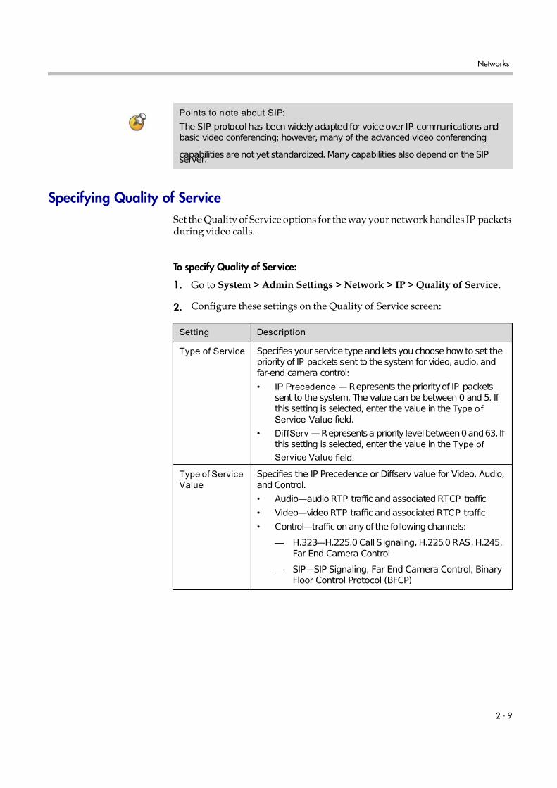
Specifying Quality of Service
Set the Quality of Service options for the way your network handles IP packetsduring video calls.
To specify Quality of Service:
1. Go to System > Admin Settings > Network > IP > Quality of Service.
2. Configure these settings on the Quality of Service screen:
Points to note about SIP:
The SIP protocol has been widely adapted for voice over IP communications andbasic video conferencing; however, many of the advanced video conferencing
capabilities are not yet standardized. Many capabilities also depend on the SIPserver.
Setting Description
Type of Service Specifies your service type and lets you choose how to set thepriority of IP packets sent to the system for video, audio, andfar-end camera control:
• IP Precedence — Represents the priority of IP packetssent to the system. The value can be between 0 and 5. If this setting is selected, enter the value in the Type o f
Service Value field.
• DiffServ — Represents a priority level between 0 and 63. If this setting is selected, enter the value in the Type of
Service Value field.
Type of Service
Value
Specifies the IP Precedence or Diffserv value for Video, Audio,and Control.
• Audio—audio RTP traffic and associated RTCP traffic
• Video—video RTP traffic and associated RTCP traffic
• Control—traffic on any of the following channels:
— H.323—H.225.0 Call Signaling, H.225.0 RAS, H.245,Far End Camera Control
— SIP—SIP Signaling, Far End Camera Control, BinaryFloor Control Protocol (BFCP)

7/16/2019 QDX 6000 System Administrator Guide
http://slidepdf.com/reader/full/qdx-6000-system-administrator-guide 22/126
Administrator Guide for Polycom QDX 6000 System
2 - 10
3. Select and configure these settings on the Bandwidth screen:
Configuring the System for Use with a Firewall or NAT
A firewall protects an organization’s IP network by controlling data trafficfrom outside the network. Unless the firewall is designed to work with H.323video conferencing equipment, you must configure the system and thefirewall to allow video conferencing traffic to pass in and out of the network.
Firewall Settings
Network Address Translation (NAT) network environments use privateinternal IP addresses for devices within the network, while using one external
IP address to allow devices on the LAN to communicate with other devicesoutside the LAN. If your system is connected to a LAN that uses a NAT, youwill need to enter the NAT Public (WAN) Address so that your system cancommunicate outside the LAN.
Maximum
Transmission
Unit Size
Specifies the Maximum Transmission Unit (MTU) size used inIP calls. If the video becomes blocky or network errors occur,
packets may be too large; decrease the MTU. If the network isburdened with unnecessary overhead, packets may be toosmall; increase the MTU.
Enable PVEC Allows the system to use PVEC (Polycom Video ErrorConcealment) if packet loss occurs.
Enable RSVP Allows the system to use Resource Reservation Setup Protocol(RSVP) to request that routers reserve bandwidth along an IPconnection path. Both the near site and far site must supportRSVP in order for reservation requests to be made to routerson the connection path.
Setting Description
Setting Description
Dynamic
Bandwidth
Specifies whether to let the system automatically find theoptimum line speed for a call.
Maximum
Transmit
Bandwidth
Specifies the maximum transmit line speed between 64 kbps andthe system’s maximum line rate.
Maximum
Receive
Bandwidth
Specifies the maximum receive line speed between 64 kbps andthe system’s maximum line rate.

7/16/2019 QDX 6000 System Administrator Guide
http://slidepdf.com/reader/full/qdx-6000-system-administrator-guide 23/126
Networks
2 - 11
To set up the system to work with a firewall or NAT:
1. Go to System > Admin Settings > Network > IP > Firewall.
2. Configure these settings on the Firewall screen:
Setting Description
Fixed Ports Lets you specify whether to define the TCP and UDP ports.
• If the firewall is not H.323 compatible, enable thissetting. The Polycom QDX 6000 system assigns arange of ports starting with the TCP and UDP ports youspecify. The system defaults to a range beginning withport 3230 for both TCP and UDP.
Note: You must open the corresponding ports in thefirewall. You must also open the firewall’s TCP port1720 to allow H.323 traffic.
• If the firewall is H.323 compatible or the system is not
behind a firewall, disable this setting.For IP you need 2 TCP ports per connection, 8 UDP portsper connection. For SIP you need TCP port 5060, 8 UDPports per connection.
TCP Ports
UDP Ports
Lets you specify the beginning value for the range of TCPand UDP ports used by the system. The systemautomatically sets the range of ports based on thebeginning value you set.
Note: You must also open the firewall’s TCP port 1720 toallow H.323 traffic.
Enable H.460
Firewall Traversal
Allows the system to use H.460-based firewall traversal forIP calls. For more information, refer to H.460 NAT Firewall
Traversal on page 2-12.
NAT Configuration Lets you specify whether the system should determine theNAT Public WAN Address automatically.
• If the system is not behind a NAT or is connected to theIP network through a Virtual Private Network (VPN),select Off .
• If the system is behind a NAT that allows HTTP traffic,select Auto .
• If the system is behind a NAT that does not allow HTTPtraffic, select Manual.
NAT Public (WAN)
Address
Displays the address that callers from outside the LAN useto call your system. If you chose to configure the NATmanually, enter the NAT Public Address here.
NAT is H.323
Compatible
Specifies that the system is behind a NAT that is capable of translating H.323 traffic.
Address Displayed
in Global Directory
Lets you choose whether to display this system’s public orprivate address in the global directory.

7/16/2019 QDX 6000 System Administrator Guide
http://slidepdf.com/reader/full/qdx-6000-system-administrator-guide 24/126
Administrator Guide for Polycom QDX 6000 System
2 - 12
H.460 NAT Firewall Traversal
You can configure Polycom QDX 6000 systems to use standards-basedH.460.18 and H.460.19 firewall traversal, which allows video systems to moreeasily establish IP connections across firewalls.
The following illustration shows how a service provider might provide H.460firewall traversal between two enterprise locations. In this example thePolycom Video Border Proxy™ (VBP™) firewall traversal device is on theedge of the service provider network and facilitates IP calls between PolycomQDX 6000 systems behind different firewalls.
To use this traversal, Polycom QDX 6000 systems and firewalls must beconfigured as follows:
• Enable firewall traversal on the Polycom QDX 6000 system.
a. Go to System > Admin Settings > Network > IP > Firewall.
b. Select Enable H.460 Firewall Traversal.
• Register the Polycom QDX 6000 system to an external Polycom VBPdevice that supports the H.460.18 and H.460.19 standards.
• Make sure that firewalls being traversed allow Polycom QDX 6000
systems behind them to open outbound TCP and UDP connections.— Firewalls with a stricter rule set should allow Polycom QDX 6000
systems to open at least the following outbound TCP and UDP ports:1720 (TCP), 14085-15084 (TCP) and 1719 (UDP), 16386-25386 (UDP).
— Firewalls should permit inbound traffic to TCP and UDP ports thathave been opened earlier in the outbound direction.
Visit the Polycom Security section of the Knowledge Base at www.polycom.comfortimely security information. Systems deployed outside a firewall are potentiallyvulnerable to unauthorized access. You can also register to receive periodic email
updates and advisories.
Gatekeeper
IP Network
System with
Enterprise Location A Enterprise Location B
Service Provider
Polycom VBP device
Traversal Enabled
System with Traversal Enabled
that Supports H.460.18and H.460.19

7/16/2019 QDX 6000 System Administrator Guide
http://slidepdf.com/reader/full/qdx-6000-system-administrator-guide 25/126
Networks
2 - 13
Configuring Call PreferencesCall preferences help you manage the network bandwidth used for calls. Youcan specify the default and optional call settings for outgoing calls. You can
also limit the call speeds of incoming calls.
To choose call preferences:
1. Go to System > Admin Settings > Network > Call Preference.
2. Configure these settings on the Call Preference screen:
3. Select and configure these settings on the Network Dialing screen:
Setting Description
Basic Mode Enables a limited operating mode that uses H.261 forvideo and G.711 for audio. This mode providesadministrators with a workaround for interoperability
issues that cannot be solved using other methods. The Basic Mode setting stays in effect until youchange it.
Basic Mode disables many system features such ascontent sharing, far end camera control, andadvanced audio and video algorithms. Use BasicMode only when calling systems that fail to operateproperly with these advanced features.
IP H.323 Allows the system to make IP calls.
SIP Allows the system to use SIP when connecting IPcalls.
H.264 Specifies that the system should use H.264 for video.
H.239 Specifies standards-based People+Content datacollaboration. Enable this option if you know thatH.239 is supported by the far sites you will call. If callers experience issues when sharing content withother Polycom systems, disable this setting.
H.264 Content If this option is enabled, the endpoint will use H.264protocol firstly when it is sending content. Someendpoints have the content which is not compatiblewith H.264, enabling this option may disable thecontent feature. In this case, it is recommended todisable this option.
ISDN Gateway Allows users to place IP-to-ISDN calls through agateway.
7/16/2019 QDX 6000 System Administrator Guide
http://slidepdf.com/reader/full/qdx-6000-system-administrator-guide 26/126
Administrator Guide for Polycom QDX 6000 System
2 - 14
4. Select to go to the Preferred Speeds screens and configure thesesettings:
5. Select to go to the Call Speeds screen and specify the call speeds tomake available to users.
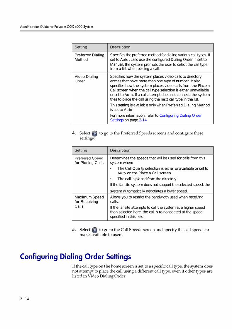
Configuring Dialing Order SettingsIf the call type on the home screen is set to a specific call type, the system doesnot attempt to place the call using a different call type, even if other types arelisted in Video Dialing Order.
Setting Description
Preferred Dialing
Method
Specifies the preferred method for dialing various call types. If set to Auto , calls use the configured Dialing Order. If set toManual, the system prompts the user to select the call typefrom a list when placing a call.
Video Dialing
Order
Specifies how the system places video calls to directoryentries that have more than one type of number. It alsospecifies how the system places video calls from the Place aCall screen when the call type selection is either unavailableor set to Auto. If a call attempt does not connect, the systemtries to place the call using the next call type in the list.
This setting is available only whenPreferred Dialing Method is set to Auto.
For more information, refer to Configuring Dialing OrderSettings on page 2-14.
Setting Description
Preferred Speed
for Placing Calls
Determines the speeds that will be used for calls from thissystem when:
• The Call Quality selection is either unavailable or set to Auto on the Place a Call screen
• The call is placed from the directory
If the far-site system does not support the selected speed, the
system automatically negotiates a lower speed.
Maximum Speed
for Receiving
Calls
Allows you to restrict the bandwidth used when receivingcalls.
If the far site attempts to call the system at a higher speedthan selected here, the call is re-negotiated at the speedspecified in this field.

7/16/2019 QDX 6000 System Administrator Guide
http://slidepdf.com/reader/full/qdx-6000-system-administrator-guide 27/126
Networks
2 - 15
You can configure the Polycom QDX 6000 system so that users can choose toplace IP-to-ISDN calls through a gateway.
To allow users to place an IP-to-ISDN call through a gateway:1. Make sure the system is registered with a gatekeeper.
2. Go to System > Admin Settings > Network > Call Preference and enable ISDN Gateway.
3. If you want to allow users to place IP-to-ISDN calls through a gatewaywhen calling from the directory, do one of the following:
— On the Network Dialing screen, set Preferred Dialing Method toAuto and select ISDN Gateway as the first choice under VideoDialing Order. With this configuration, IP-to-ISDN calls placed fromthe directory will be placed through a gateway if an ISDN number andIP extension exist. IP-to-IP calls placed from the directory will be
placed through a gateway if an IP address and IP extension exist.
— On the Network Dialing screen, set Preferred Dialing Method toManual. With this configuration, users can select ISDN Gateway from the list of call types that appears when placing a call from thedirectory.

7/16/2019 QDX 6000 System Administrator Guide
http://slidepdf.com/reader/full/qdx-6000-system-administrator-guide 28/126
Administrator Guide for Polycom QDX 6000 System
2 - 16

7/16/2019 QDX 6000 System Administrator Guide
http://slidepdf.com/reader/full/qdx-6000-system-administrator-guide 29/126
3 - 1
3
Monitors and Cameras
Connecting MonitorsMake sure that the system is powered off before you connect devices.
The following table shows how you can connect monitors to a Polycom QDX6000 system.
The Polycom QDX 6000 system user interface is displayed on Monitor 1.
Video Output Number Connector Output Formats
1 RCA (three) YPrPb
RCA (yellow) Composite
S-Video S-Video
2 RCA (yellow) Composite
S-Video S-Video
VGA VGA
For Monitor 2, the system provides RCA, S-Video, and VGA connectors. Only oneat a time is active, based on the output format configured for that monitor.
7/16/2019 QDX 6000 System Administrator Guide
http://slidepdf.com/reader/full/qdx-6000-system-administrator-guide 30/126
Administrator Guide for Polycom QDX 6000 System
3 - 2
Configuring Monitor Settings
To configure monitors:1. Go to System > Admin Settings > Monitors.
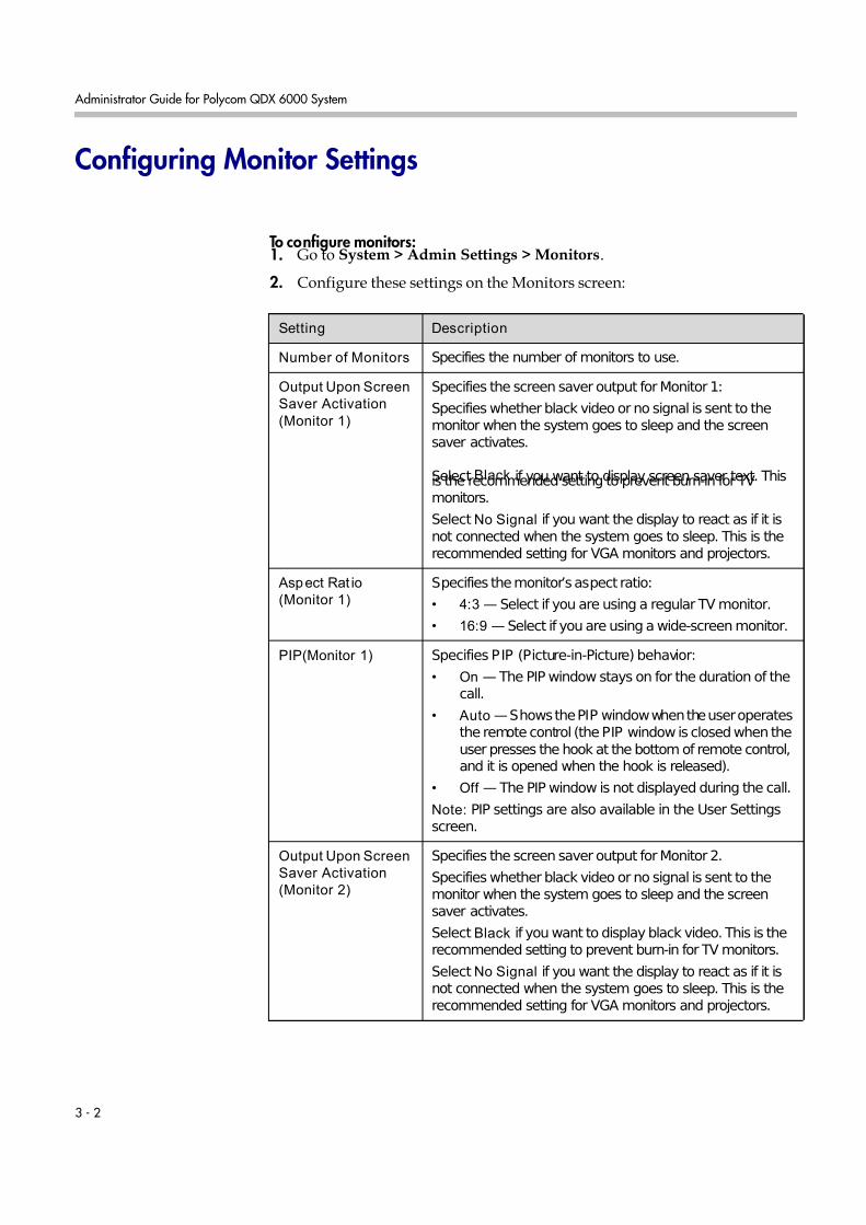
2. Configure these settings on the Monitors screen:
Setting Description
Number of Monitors Specifies the number of monitors to use.
Output Upon Screen
Saver Activation (Monitor 1)
Specifies the screen saver output for Monitor 1:
Specifies whether black video or no signal is sent to themonitor when the system goes to sleep and the screensaver activates.
Select Black if you want to display screen saver text. Thisis the recommended setting to prevent burn-in for TVmonitors.
Select No Signal if you want the display to react as if it isnot connected when the system goes to sleep. This is therecommended setting for VGA monitors and projectors.
Aspect Rat io
(Monitor 1)
Specifies the monitor’s aspect ratio:
• 4:3 — Select if you are using a regular TV monitor.
• 16:9 — Select if you are using a wide-screen monitor.
PIP(Monitor 1) Specifies PIP (Picture-in-Picture) behavior:
• On — The PIP window stays on for the duration of thecall.
• Auto — Shows the PIP window when the user operatesthe remote control (the PIP window is closed when theuser presses the hook at the bottom of remote control,and it is opened when the hook is released).
• Off — The PIP window is not displayed during the call.
Note: PIP settings are also available in the User Settingsscreen.
Output Upon Screen
Saver Activation (Monitor 2)
Specifies the screen saver output for Monitor 2.
Specifies whether black video or no signal is sent to themonitor when the system goes to sleep and the screensaver activates.
Select Black if you want to display black video. This is therecommended setting to prevent burn-in for TV monitors.
Select No Signal if you want the display to react as if it isnot connected when the system goes to sleep. This is therecommended setting for VGA monitors and projectors.

7/16/2019 QDX 6000 System Administrator Guide
http://slidepdf.com/reader/full/qdx-6000-system-administrator-guide 31/126
Monitors and Cameras
3 - 3
3. Select and configure these settings:
Aspect Rat io
(Monitor 2)
Specifies the monitor’s aspect ratio:
• 4:3 — Select if you are using a regular TV monitor.
• 16:9 — Select if you are using a wide-screen monitor.
Video Format (Monitor 2)
Specifies the monitor’s format:
• VGA — Select if the monitor is connected to the DVIconnector using a VGA cable.
• TV — Select if the TV is connected using a compositevideo cable or S-video cable.
VGA Resolution (Monitor 2)
Specifies the resolution for the monitor.
Setting Description
Setting Description
People Video
Adjustment,
Content
Video
Adjustment
Specifies the adjustment made to people video and content videoimages.
• None—Preserves the aspect ratio of the source video. Theimage is scaled (if necessary) to the largest supportedresolution that fits on the display without cropping. Extraareas on the display are filled with black borders.
• Stretch—Does not preserve aspect ratio. The image isscaled horizontally and vertically to exactly match theresolution of the display.
• Zoom—Preserves the aspect ratio of the source video. Theimage is scaled to exactly match one of the displaydimensions while matching or exceeding the other displaydimension. The image is centered and cropped.
Display Icons
in a Call Specifies whether to display all on-screen graphics, includingicons and help text, during calls.
Screen Saver
Wait Time
Specifies how long the system remains awake during periods of inactivity. The default is 3 minutes. If the system requires users tolog in, the screen saver timeout also logs out the current user.
Setting this option to Off prevents the system from going to sleep. To prevent image burn-in, specify 3 minutes or less.
Color System Specifies the color system used by your monitor.
Changing this setting causes the system to restart.

7/16/2019 QDX 6000 System Administrator Guide
http://slidepdf.com/reader/full/qdx-6000-system-administrator-guide 32/126
Administrator Guide for Polycom QDX 6000 System
3 - 4
Adjusting Screen Layout
In calls, you can change the current screen layout on the monitor. What yousee during a call can depend on factors such as the system monitor
configuration, the number of sites in the call, whether the Picture-in-Picture(PIP) is enabled and whether the content is being shared.
To change the screen layout:
In a call, repeatedly press PIP on the remote control to switch amongthe screen layouts supported by the Polycom QDX 6000 system. Thesemight include the following layouts:
Specifying, Showing and Turning Off the PIPYour system can be configured to display a Picture-in-Picture (PIP) window ifyour monitor is set to an aspect ratio of 4:3. You can show the PIP any time thesystem is not sending or receiving content.
1. Far site, full screen
2. Far and near sites, the same size, side by side
3. Far site big, near site small (only available whenyour monitor is configured to 16:9)
4. Far site displayed in full screen, and near site inthe right-bottom small window (PIP layout, onlyavailable when your monitor is configured to 4:3)
5. Content displayed in the left big window, and farand near sites in the right small window
7/16/2019 QDX 6000 System Administrator Guide
http://slidepdf.com/reader/full/qdx-6000-system-administrator-guide 33/126
Monitors and Cameras
3 - 5
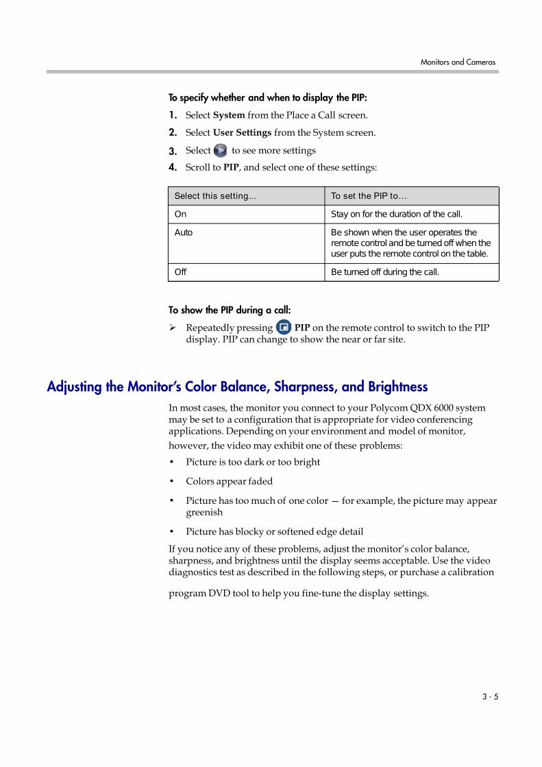
To specify whether and when to display the PIP:
1. Select System from the Place a Call screen.
2. Select User Settings from the System screen.
3. Select to see more settings
4. Scroll to PIP, and select one of these settings:
To show the PIP during a call:
Repeatedly pressing PIP on the remote control to switch to the PIPdisplay. PIP can change to show the near or far site.
Adjusting the Monitor’s Color Balance, Sharpness, and Brightness
In most cases, the monitor you connect to your Polycom QDX 6000 systemmay be set to a configuration that is appropriate for video conferencingapplications. Depending on your environment and model of monitor,
however, the video may exhibit one of these problems:
• Picture is too dark or too bright
• Colors appear faded
• Picture has too much of one color — for example, the picture may appeargreenish
• Picture has blocky or softened edge detail
If you notice any of these problems, adjust the monitor’s color balance,sharpness, and brightness until the display seems acceptable. Use the videodiagnostics test as described in the following steps, or purchase a calibration
program DVD tool to help you fine-tune the display settings.
Select this setting... To set the PIP to…
On Stay on for the duration of the call.
Auto Be shown when the user operates theremote control and be turned off when theuser puts the remote control on the table.
Off Be turned off during the call.

7/16/2019 QDX 6000 System Administrator Guide
http://slidepdf.com/reader/full/qdx-6000-system-administrator-guide 34/126
Administrator Guide for Polycom QDX 6000 System
3 - 6
To adjust the monitor for natural color:
1. Go to System > Diagnostics > Video.
2. Select the color bars icon to display the color bar test screen.
3. Adjust the color using the monitor’s controls for color, contrast, andbrightness. Your monitor may also have controls for tint andtemperature.
The colors from left to right should be white, yellow, cyan, green,magenta, red, and blue. Make sure that the white is not tinted red, green,or blue, and that the red is not tinted pink or orange.
4. When the colors look right on the test screen, press Near until you seevideo of the room.
5. If the color appears natural, you do not need to make furtheradjustments.
If the color still needs adjustment, use the monitor’s controls to make smalladjustments until the picture appears natural.
Preventing Monitor Burn-In
Monitors and Polycom QDX 6000 systems provide display settings to helpprevent image burn-in. Plasma televisions can be particularly vulnerable tothis problem. Refer to your monitor’s documentation or manufacturer forspecific recommendations and instructions. The following guidelines helpprevent image burn-in:
• For monitors that support low-power mode when no signal is present onthe monitor input, set Output upon Screen Saver Activation to NoSignal. For example, use the No Signal setting on VGA monitors andmonitors provided by Polycom. Otherwise, set Output upon Screen SaverActivation to Black.
• Use the monitor’s burn-in prevention features, if available.
• Ensure that static images are not displayed for long periods.
• Set the Screen Saver Wait Time to 3 minutes or less.
• To keep the screen clear of static images during a call, disable thefollowing settings:
— Display Icons in a Call described on page 3-3
— Display Time in Call described on page 6-1
— Far Site Name Display Time described on page 6-2
• Be aware that meetings that last more than an hour without muchmovement can have the same effect as a static image.

7/16/2019 QDX 6000 System Administrator Guide
http://slidepdf.com/reader/full/qdx-6000-system-administrator-guide 35/126
Monitors and Cameras
3 - 7
• Consider decreasing the monitor’s sharpness, brightness, and contrastsettings if they are set to their maximum values.
Connecting CamerasPolycom QDX 6000 systems provide inputs for PTZ cameras. You can use theRS-232 serial port on the system to control supported non-Polycom cameras orcameras not connected to a main camera input.
Refer to your system’s setup sheet for connection details. If you connect asupported PTZ camera, the system detects the camera type and sets theappropriate configuration. Make sure that the system is powered off beforeyou connect devices to it.
Connecting Cameras to Polycom QDX 6000 SystemsThe following table shows how you can connect video sources to a PolycomQDX 6000 system.
Video Input
Number Connector Acceptable Input Power Control
1 (main
camera)
S-Video S-Video Provided Camera PTZ,IR Input
2 (auxiliary
camera)
RCA Composite None None
3 (documentcamera)
S-Video S-Video None None
4 (VCR) RCA Composite None None
5 (VGA) VGA VGA None None

7/16/2019 QDX 6000 System Administrator Guide
http://slidepdf.com/reader/full/qdx-6000-system-administrator-guide 36/126
Administrator Guide for Polycom QDX 6000 System
3 - 8
Configuring Camera Settings and Video Quality Options
To configure camera and video settings:1. Go to System > Admin Settings > Cameras.
2. Configure these settings on the Cameras screen:
3. Select and configure these settings:
Setting Description
Camera 1 The camera’s aspect ratio:
• 4:3 — You are using a regular camera.
• 16:9 — You are using a camera in wide-screen mode. Polycom EagleEye SD
The camera’s format:
S-Video — The camera is connected to the Polycom QDX6000 system using an S-Video cable.
Name Specifies a name and icon for the camera.
Video Quality Specifies Motion orSharpness for the video input. Thedefault is Sharpness.
• Motion — This setting is for showing people or othervideo with motion.
• Sharpness — The picture will be sharp and clear, butmoderate to heavy motion at low call rates can causesome frames to be dropped.
Camera Pan/Tile
Speed
Sets the camera pan rate.
• Slow - The camera pans at a low rate.• Medium - The camera pans at a medium rate.
• Fast - The camera pans at a high rate.
Detect Camera Detects any supported PTZ camera connected to PolycomQDX 6000 system video input 1 and configures the camerasettings accordingly.
Setting Description
Camera 2 Specifies the camera’s aspect ratio:
• 4:3 — Select if you are using a regular camera.
• 16:9 — Select if you are using a wide-screen camera.
The camera’s format:
Composite — The camera is connected to the PolycomQDX 6000 system using a composite video cable.

7/16/2019 QDX 6000 System Administrator Guide
http://slidepdf.com/reader/full/qdx-6000-system-administrator-guide 37/126
Monitors and Cameras
3 - 9
4. Select and configure these settings:
5. Select and configure these settings:
Name Specifies a name and icon for the camera.
Video Quality Specifies Motion orSharpness for the video input.
• Motion — This setting is for showing people or othervideo with motion.
• Sharpness — The picture will be sharp and clear, butmoderate to heavy motion at low call rates can causesome frames to be dropped. Sharpness is available inpoint-to-point H.263 and H.264 calls only.
Setting Description
Setting Description
Camera 3 Specifies the aspect ratio of document computer or other
video source:
• 4:3 — Select if you are using a computer with a standarddisplay.
• 16:9 — Select if you are using a computer with awide-screen display.
The format of document computer or other video source:
S-Video — The document video source is connected to thePolycom QDX 6000 system using an S-Video cable.
Name Specifies a name and icon for the document computer orvideo source.
Video Quality Specifies Motion orSharpness for the video input.
• Motion — This setting is for showing people or othervideo with motion.
• Sharpness — The picture will be sharp and clear, butmoderate to heavy motion at low call rates can causesome frames to be dropped. Sharpness is available inpoint-to-point H.263 and H.264 calls only.
Setting Description
Camera 4 Specifies the VCR or DVD player’s aspect ratio:
• 4:3 — Select if you are using a VCR or DVD player instandard mode.
• 16:9 — Select if you are using a VCR or DVD player inwide-screen mode.
The VCR or DVD player’s format:
Composite — The VCR or DVD player is connected to thePolycom QDX 6000 system using a composite video cable.

7/16/2019 QDX 6000 System Administrator Guide
http://slidepdf.com/reader/full/qdx-6000-system-administrator-guide 38/126
Administrator Guide for Polycom QDX 6000 System
3 - 10
6. Select and configure these settingss:
7. Select and configure these settings:
Name Specifies a name and icon for the VCR or DVD player.
Video Quality Specifies Motion orSharpness for the video input.
• Motion — This setting is for showing people or othervideo with motion.
• Sharpness — The picture will be sharp and clear, butmoderate to heavy motion at low call rates can causesome frames to be dropped. Sharpness is available inpoint-to-point H.263 and H.264 calls only.
Setting Description
Setting Description
Camera 5 The fifth video source (VGA IN).
Name Specifies a name and icon for the computer or video source.
Video Quality Specifies Motion orSharpness for the video input.
• Motion — This setting is for showing people or othervideo with motion.
• Sharpness — The picture will be sharp and clear, butmotion will not be smooth. Choose this setting fordocument cameras. Sharpness is available inpoint-to-point H.263 calls only.
Setting Description
Far Control of Near
Camera
Specifies whether the far site can pan, tilt, or zoom thenear-site camera. When this option is selected, a user atthe far site can control the framing and angle of the camerafor the best view of the near site.
Backlight
Compensation
Specifies whether to have the camera automatically adjustfor a bright background. Backlight compensation is bestused in situations where the subject appears darker thanthe background.
Primary Camera Specifies which camera is the main camera. The primarycamera is active when the Polycom QDX 6000 system
powers up. Its source is automatically set to People.
Camera Pan
Direction
Specifies the direction the camera moves when using thearrow buttons on the remote control.

7/16/2019 QDX 6000 System Administrator Guide
http://slidepdf.com/reader/full/qdx-6000-system-administrator-guide 39/126
Monitors and Cameras
3 - 11
Configuring Advanced Polycom EagleEye SD CameraSettings
You can use the system’s web interface to configure or restore the followingPolycom EagleEye SD camera settings:
• Brightness
• Black Level
• Color Saturation
• White Balance
To adjust Polycom EagleEye SD camera’s brightness, black level, or colorsaturation:
1. Make sure that the system and camera are powered on and awake.
2. On a computer, open a web browser.
3. In the browser address line, enter the system’s IP address, for example,ht t p: / / 10. 11. 12. 13, to go to the Polycom QDX 6000 web interface.
4. Go to Admin Settings > Cameras.
Quality Preference Specifies the bandwidth split for People and Content video.
• People—10% Content, 90% People
• Both—50% Content, 50% People
• Content—90% Content, 10% People
This setting does not apply if automatic bandwidthadjustment is enabled using the API.
This setting applies only to calls of 128 kbps of higher.
Power Frequency Specifies the power line frequency for your system onlywhen a Polycom EagleEye SD camera is connected.
In most cases, the system defaults to the correct powerline frequency, based on the video standard used in thecountry where the system is located. This setting allowsyou to adapt the system in areas where the power linefrequency does not match the video standard used. You
may need to change this setting to avoid flicker from thefluorescent lights in your conference room.
Changing this setting causes the system to restart. Afterthe system restarts, you might need to select Detect
Camera.
Setting Description

7/16/2019 QDX 6000 System Administrator Guide
http://slidepdf.com/reader/full/qdx-6000-system-administrator-guide 40/126
Administrator Guide for Polycom QDX 6000 System
3 - 12
5. If Model is not set to Polycom EagleEye SD for the appropriate camera(s),click the Detect Camera button.
6. Click Advanced.
7. Select values for brightness, black level, and color saturation.8. Click Update.
To restore the Polycom EagleEye SD camera’s default settings:
1. Make sure that the system and camera are powered on and awake.
2. On a computer, open a web browser.
3. In the browser address line, enter the system’s IP address, for example,ht t p: / / 10. 11. 12. 13, to go to the Polycom QDX 6000 web interface.
4. Go to Admin Settings > Cameras.
5. Click Restore. White Balance, Brightness, Black Level, and ColorSaturation are returned to their default values.
To set the Polycom EagleEye SD white balance:
You can set the white balance to one of several fixed values, or you can set itmanually.
1. Make sure that the system and camera are powered on and awake.
2. On a computer, open a web browser.
3. In the browser address line, enter the system’s IP address, for example,ht t p: / / 10. 11. 12. 13, to go to the Polycom QDX 6000 web interface.
4. Go to Admin Settings > Cameras.
5. If Model is not set to Polycom EagleEye SD for the appropriate camera(s),click the Detect Camera button.
6. Select a value for White Balance.
— Auto: Polycom recommends this setting for most situations. It
calculates the best white balance setting based on lighting conditionsin the room.
— Pre-defined values: Use one of the pre-defined color temperaturesettings to provide acceptable color reproduction.
White balance settings require particular camera and system firmware versions.For more information, contact your Polycom distributor or refer to the KnowledgeBase in the Support section of the Polycom web site.

7/16/2019 QDX 6000 System Administrator Guide
http://slidepdf.com/reader/full/qdx-6000-system-administrator-guide 41/126
Monitors and Cameras
3 - 13
— Manual: Use the Manual setting for rooms where the Auto and fixedsettings do not provide acceptable color reproduction. Set the WhiteBalance to Manual. Then fill the camera view with a flat white surfaceand click Calibrate.
7. Click Update.
Configuring Camera PresetsCamera presets are stored camera positions that you can create ahead of timeor during a call.
Presets allow you to:
• Automatically point a camera at pre-defined locations in a room.
• Select a video source.If your camera supports pan, tilt, and zoom movement, you can create up to100 preset camera positions for it. Each preset stores the camera number, itszoom level, and the direction it points (if appropriate). Presets remain in effectuntil you delete or change them.
To store a preset (Using remote control):
1. If you are in a call, press Near or Far then choose a near-site or far-sitecamera or other video source.
2. If you selected a camera that supports electronic pan, tilt, and zoom, you
can adjust the camera’s position:— Press Zoom to zoom the camera out or in.
— Press the arrow buttons on the remote control to move the camera up,down, left, or right.
3. Press and hold a number to store the preset position.
To store a double-digit preset (10-99), hold the second number down.
Any existing preset stored at the number you enter is replaced.
To delete all presets on a Polycom QDX 6000 system (Using remote control):
1. If a call is connected, press Near to choose a near-site video source.2. Press Preset on the remote control.
3. Press and hold Delete to delete all presets.

7/16/2019 QDX 6000 System Administrator Guide
http://slidepdf.com/reader/full/qdx-6000-system-administrator-guide 42/126
Administrator Guide for Polycom QDX 6000 System
3 - 14

7/16/2019 QDX 6000 System Administrator Guide
http://slidepdf.com/reader/full/qdx-6000-system-administrator-guide 43/126
4 - 1
4
Microphones and Speakers
Connecting Audio Input Make sure that the system is powered off before you connect devices to it.
Connecting Audio Input to Polycom QDX 6000 Systems
The following table shows the acceptable input levels and video associationsfor the audio inputs on a Polycom QDX 6000 system.
Connecting Devices to the Polycom QDX 6000 Microphone Input
To pick up audio from your site, you must connect a microphone to thePolycom QDX 6000 system. Refer to your system’s setup sheet for connectiondetails.
The microphone picks up sound from the sides. You can connect two Polycommicrophones to a Polycom QDX 6000 system.
Audio Input Number Connector Acceptable Inpu t Source Levels Video Ass ociat ion
Mic 1 RJ -9 Polycom microphone None
Mic 2 RJ -9 Polycom microphone None
Line In (Main Audio) RCA Line Level None
VCR IN (VCR/DVDPlayer)
RCA Mono/Stereo Line Level Can be associated to any videosource, or without association toa video source. For moreinformation about this setting,refer to Auxiliary Audio InputAssociation on page 4-5.

7/16/2019 QDX 6000 System Administrator Guide
http://slidepdf.com/reader/full/qdx-6000-system-administrator-guide 44/126
Administrator Guide for Polycom QDX 6000 System
4 - 2
For best audio:
• Place the microphone on a hard, flat surface (table, wall, or ceiling) awayfrom obstructions, so the sound will be directed into the microphoneelements properly.
• Place the microphone near the people closest to the monitor.
• In large conference rooms, you may need more than one microphone.Each Polycom microphone covers a 3-6 foot radius, depending on thenoise level and acoustics in the room.
Polycom Microphone Lights
The following table describes the behavior of the microphone lights.
Connecting Audio Output You must connect at least one speaker to Polycom QDX 6000 systems in orderto hear audio. You can use the speakers built into the main monitor, or you can
connect an external speaker system such as the Polycom StereoSurround kit toprovide more volume and richer sound in large rooms.
Refer to your system’s setup sheet for connection details. Make sure that thesystem is powered off before you connect devices to it.
Connecting Speakers to Polycom QDX 6000 Systems
The following table describes the audio outputs of the Polycom QDX 6000system.
Microphone Light Status
Off Not in a call
Green In a call, mute off
Red Mute on
Audio Output Number Connector Output Type Audio Mix Rou ted to the Output
Line Out (Main Audio) RCA Mono/Stereo System tones and sound effects +Audio from the far site
VCR OUT (VCR/DVD
Player)
RCA Mono/Stereo Near-site talkers +Audio from the far site

7/16/2019 QDX 6000 System Administrator Guide
http://slidepdf.com/reader/full/qdx-6000-system-administrator-guide 45/126
Microphones and Speakers
4 - 3
Setting the Speaker Volume
To set the volume of an external speaker system:
1. Go to System > Diagnostics >Audio > Speaker Test.
2. Start the speaker test.
3. Adjust the volume of the speaker system. From the center of the room thetest tone should be as loud as a person speaking loudly, about 80-90 dBAon a sound pressure level meter.
Configuring Audio Settings
General Audio Settings
To configure general audio settings:
1. Go to System > Admin Settings >Audio > Audio Settings.
2. Configure these settings on the Audio Settings screen:
To configure audio input/output settings:
1. Go to System > Admin Settings >Audio > Inputs/Outputs.
2. Configure these settings on the Audio Input screen:
Setting Description
Sound Effects
Volume
Sets the volume level of the ring tone and user alert
tones.
Incoming Video Call Specifies the ring tone used for incoming calls.
User Alert Tones Specifies the tone used for user alerts.
Mute Auto Answer
Calls
Specifies whether to mute your microphone when autoanswering incoming calls.
when auto answering incoming calls, your microphone ismuted by default until you press the mute button on themicrophone or on the remote control.

7/16/2019 QDX 6000 System Administrator Guide
http://slidepdf.com/reader/full/qdx-6000-system-administrator-guide 46/126
Administrator Guide for Polycom QDX 6000 System
4 - 4
3. Select and enter these settings on the Audio Output screen:
Setting Description
Microphone Level Sets the volume level for microphone input.
Line In Level Sets the volume level for line input.
Echo Canceller Lets you specify whether to use the system’s built-in echocanceller with line audio input.
Note: This setting only affects line input. Typically,microphones connected to the Polycom microphone inputare automatically echo cancelled.
Microphones
(dB meter)
Lets you see the peak input signal level present at themicrophones.
Line Input
(dB meter)
Lets you see the peak input signal level present at the lineinput.
Echo Ccanceller
(dB meter)
Lets you see the peak input signal level present at the
echo canceller.
Setting Description
Line Output Mode Specifies whether volume for a device connected to theaudio line out connectors is variable or fixed.
• Variable—Allows users to set the volume with theremote control.
• Fixed—Sets the volume to the Audio Level specified inthe system interface.
Note: When this setting is set to Fixed, the remotecontrol’s volume adjustment does not affect the outputlevel of line output.
Level Sets the volume level for line output when Line Output
Mode is set to Fixed.
Line Out (dB meter) Lets you see the peak output signal level present at lineoutput.

7/16/2019 QDX 6000 System Administrator Guide
http://slidepdf.com/reader/full/qdx-6000-system-administrator-guide 47/126
Microphones and Speakers
4 - 5
4. Select and enter these settings on the VCR/DVD screen:
5. Select and enter these settings on the Audio Levels screen:
StereoSurround Settings
To send or receive stereo audio, make sure your Polycom QDX 6000 systemequipment is set up as described in Connecting Devices to the Polycom QDX6000 Microphone Input on page 4-1 and Connecting Audio Output on page
4-2. Then configure the system to use Polycom StereoSurround, test the systemconfiguration, and place a test call.
Setting Description
Line In Level Sets the volume level for VCR or DVD input.
Line Out Level Sets the volume level for VCR or DVD output.
Auxi liary Audio
Input Association
Sets whether to associate current video source. If it is setto associate current video source, you can hear theVCR/DVD player audio through Line Output audio.
If you want to play the VCR/DVD player audio through LineOutput audio, do one of the following,
• If current video source is the main camera, set thissetting to Main Camera.
• If current video source is AUX / DOC / VCR / VGA, setto corresponding video source.
VCR/DVD AudioOut Always On
Allows you to record a call using one VCR or DVD, whileplaying content into the call from a second VCR or DVD.
Do not select this setting if you have only one VCR or DVDplayer connected. If this setting is disabled, the VCR audiooutput is disabled when VCR is the selected camerasource.
Line In Level
(dB meter)
Lets you see the peak input signal level present at VCR orDVD audio input.
Line Out Level
(dB meter)
Lets you see the peak output signal level present at VCRor DVD audio output.
Setting Description
Master Audio
Volume
Sets the volume level for audio from the far site.

7/16/2019 QDX 6000 System Administrator Guide
http://slidepdf.com/reader/full/qdx-6000-system-administrator-guide 48/126
Administrator Guide for Polycom QDX 6000 System
4 - 6
To configure stereo settings:
1. Go to System > Admin Settings >Audio > Stereo Settings.
2. Configure these settings on the Stereo Settings screen:
Audio Meters
The audio meters in the user interface allow you to identify left and rightchannels. The meters also indicate peak signal levels. Set signal levels so thatyou see peaks between +3 dB and +7 dB with normal speech and programmaterial. Occasional peaks of +12 dB to +16 dB with loud transient noises areacceptable. If you see +20 on the audio meter, the audio signal is 0 dBFS andthe audio might be distorted.
Testing StereoSurround
After you configure the system to use Polycom StereoSurround, test thesystem configuration and place a test call.
To test your stereo configuration:
1. Go to System > Admin Settings > Audio > Stereo Settings.
Make sure the microphones are positioned correctly.
2. Go to System > Admin Settings > Audio > Stereo Settings.
Gently blow on the left leg and right leg of each Polycom microphonewhile watching the Left and Right meters to identify the left and rightinputs.
3. Go to System > Admin Settings > Audio > Stereo Settings > .
Test the speakers to check volume and verify that audio cables areconnected. If the system is in a call, the far site hears the tone.
Exchange the right and left speakers if they are reversed.
Adjust the volume control on your external audio amplifier so that the testtone sounds as loud as a person speaking in the room. If you are using aSound Pressure Level (SPL) meter, it should measure about 80-90 dBA inthe middle of the room.
Setting Description
Enable Polycom
StereoSurround
Specifies that Polycom StereoSurround is used for allcalls.
To send or receive stereo audio, make sure your PolycomQDX 6000 system is set up as described in ConnectingDevices to the Polycom QDX 6000 Microphone Input onpage 4-1 and Connecting Audio Outputon page 4-2.

7/16/2019 QDX 6000 System Administrator Guide
http://slidepdf.com/reader/full/qdx-6000-system-administrator-guide 49/126
Microphones and Speakers
4 - 7
To make a test call in stereo:
Select Polycom Austin Stereo from the directory, or enterst er eo. pol ycom. comin the dialing field and press Call on theremote control or keypad.
The Polycom Austin Stereo site demonstrates the stereo feature with anentertaining and informative presentation.

7/16/2019 QDX 6000 System Administrator Guide
http://slidepdf.com/reader/full/qdx-6000-system-administrator-guide 50/126
Administrator Guide for Polycom QDX 6000 System
4 - 8

7/16/2019 QDX 6000 System Administrator Guide
http://slidepdf.com/reader/full/qdx-6000-system-administrator-guide 51/126
5 - 1
5
Content and Captions
You can present content during calls when you use sources such as thefollowing:
• A VCR or DVD player connected directly to a Polycom QDX 6000 system
• People+Content IP installed on a computer, with any Polycom QDX 6000system that has the People+Content IP option installed
• A computer connected directly to a Polycom QDX 6000 system
For more information about sharing content during a call, refer to the User Guide for Polycom QDX 6000 Systems.
Connecting VCR/DVDsYou can connect a VCR or DVD player to a Polycom QDX 6000 system to play
videotapes or DVDs into calls.
Configuring VCR/DVD Player SettingsYou can connect a VCR or DVD player to Polycom QDX 6000 systems.
Playing a Videotape or DVD
The VCR/DVD inputs are active when you select the camera sourceconfigured as VCR. The microphone inputs remain active while the VCR orDVD player is playing. Call participants may wish to mute the microphoneswhile playing videotapes or DVDs. when you select VCR as the current videosource, you can associate the VCR / DVD player audio with VCR videosource. For detail setting on this, please refer to Auxiliary Audio InputAssociation on page 4-5.

7/16/2019 QDX 6000 System Administrator Guide
http://slidepdf.com/reader/full/qdx-6000-system-administrator-guide 52/126
Administrator Guide for Polycom QDX 6000 System
5 - 2
To configure VCR/DVD audio settings for playing a videotape or DVD:
1. Go to System > Admin Settings > Audio > Inputs/Outputs > > .
2. Set Line In Level for playback volume of the VCR/DVD player relative
to other audio from the system.3. Enable VCR/DVD Audio Out Always On unless you have the
VCR/DVD inputs and outputs both connected to the same device to playand record.
Connecting Computers to Polycom QDX 6000 SystemsYou can connect a computer directly to a Polycom QDX 6000 system. Whenyou do this, other call participants can see everything that you see on yourcomputer.
When you connect to video and audio from your computer, the audio is mutedunless the computer is selected as a video source.
For more information about connecting computers as content video sourcesfor Polycom QDX 6000 systems, refer to Connecting Cameras on page 3-7.Refer to your system’s setup sheet for connection details.
Configuring Content Sharing
To configure the content display:1. Go to System > Admin Settings > Network > Call Preference.
2. Enable H.239.
Setting Description
Enable H.239 Select this option if you know that H.239 issupported by the far sites you will call. If callers experiencing issues when sharingcontent with other Polycom systems,disable this setting.

7/16/2019 QDX 6000 System Administrator Guide
http://slidepdf.com/reader/full/qdx-6000-system-administrator-guide 53/126
Content and Captions
5 - 3
Configuring Content Display with People+Content IPPeople+Content IP enables a presenter to show content from a computer toother sites in a video conference using only an IP network connection.The
presenter can show PowerPoint® slides, video clips, spreadsheets, or anyother type of content from a computer. People+Content IP supports anycomputer desktop resolution with color set to 16-bit or higher.
Before a presenter can use a computer to show content withPeople+Content IP, you need to:
• Download the People+Content IP software application from the Polycomweb site to the computer(s) that the presenter will use to show content.
You don’t need to change the computer resolutions and you don’t needspecial cables or hardware, but the computer(s) must meet theserequirements:
— Operating System: Windows 2000, Windows XP Home, or WindowsXP Professional
— Minimum computer: 500 MHz Pentium® III (or equivalent); 256 MBmemoryRecommended computer: 1 GHz Pentium III (or equivalent); 512 MBmemory
• Connect the computer(s) to the IP network.
To install People+Content IP on a computer:
1. On a computer with Windows XP or Windows 2000, open a web browser
and go to the Polycom web site at www.polycom.com/support.2. Navigate to your product page.
3. Download and install the People+Content IP software.
Configuring CaptioningTo customize your meeting, you can define a meeting name that displays onthe screen at all sites. For example, your meeting name might be BeijingExecutive Team. You can also define text that all participants see movingacross the screen (a "rolling caption"). For example, your rolling caption might
be "For technical support, call technical support at 597-636-557".

7/16/2019 QDX 6000 System Administrator Guide
http://slidepdf.com/reader/full/qdx-6000-system-administrator-guide 54/126
Administrator Guide for Polycom QDX 6000 System
5 - 4
Configuring Meeting Captions
To configure the meeting caption:
1. Go to System > Utilities> Meeting Caption.
2. Configure these settings on the Meeting Caption screen:
Configuring Rolling Captions
To configure the rolling caption:
1. Go to System > Utilities > Rolling Caption.2. Configure these settings on the Rolling Caption screen:
setting description
Enable Meeting Caption Specifies whether to display the meetingname to all sites in a call.
Meeting Name Specifies the meeting name used for thissystem. Meeting names can contain up to10 double-byte or 20 single-byte letters,numbers, symbols, and Chinese
characters.
Color Sets the display color of the meetingname.
Caption Position Specifies the display position of the localmeeting name.
• Top Left - The meeting name isshown in the upper left corner of thescreen.
• Top Right - The meeting name isshown in the upper right corner of thescreen.
• Bottom Left - The meeting name isshown in the lower left corner of thescreen.
• Bottom Right - The meeting name isshown in the lower right corner of thescreen.

7/16/2019 QDX 6000 System Administrator Guide
http://slidepdf.com/reader/full/qdx-6000-system-administrator-guide 55/126
Content and Captions
5 - 5
Setting Description
Enable Rolling Caption Sets whether to display a moving caption
to all participants.
Color Sets the display color of caption.
Rolling Speed Sets the scrolling speed of the rollingcaption.
A scrolling speed of 1 is the slowestspeed, and 3 is the fastest.
Caption Position Sets the display position of marquee in thepicture.
Rolling Caption Text Text to display in the rolling caption. Thetext can contain letters, numbers,symbols, and Chinese characters.

7/16/2019 QDX 6000 System Administrator Guide
http://slidepdf.com/reader/full/qdx-6000-system-administrator-guide 56/126
Administrator Guide for Polycom QDX 6000 System
5 - 6

7/16/2019 QDX 6000 System Administrator Guide
http://slidepdf.com/reader/full/qdx-6000-system-administrator-guide 57/126
6 - 1
6
Calling and Answering
Configuring Call SettingsThe Call Settings screens provide access to high-level options for the entiresystem. For convenience, some of the User Settings options are repeated on
these screens.
To configure call settings:
1. Go to System > Admin Settings > General Settings > System Settings >Call Settings.
2. Configure these settings on the Call Settings screen:
Setting Description
Maximum Time in
Call
Enter the maximum number of minutes allowed for calllength.
When that time has expired, you see a message asking youif you want to hang up or stay in the call. If you do not answerwithin one minute, the call automatically disconnects. If youchoose to stay in the call at this time, you will not beprompted again.
Choosing 0 removes any limit.
This setting also applies when you are viewing the Nearvideo screen or showing content, even if you are not in acall. If the maximum time is reached while viewing Nearvideo, the system automatically returns to the home screen.If content is being shown, the content stops.
Display Time in
Call
Specifies whether to display the elapsed time or the local
time during a call. You can also choose not to display thetime.

7/16/2019 QDX 6000 System Administrator Guide
http://slidepdf.com/reader/full/qdx-6000-system-administrator-guide 58/126
Administrator Guide for Polycom QDX 6000 System
6 - 2
Setting the Call Answering Mode
To set the call answering mode:
1. Go to System > Admin Settings > General Settings > System Settings >Call Settings.
2. Select Auto Answer Point-to-Point Video to set the answer mode forcalls with one site.
3. Select one of the following:
— Yes – Answers calls automatically.
— No – Enables you to answer calls manually.
— Do Not Disturb – Refuses incoming calls automatically. The callerreceives a message that the site is unavailable.
Call Detail Report Specifies whether to collect call data for the Call DetailReport and Recent Calls list. When selected, information
about calls can be viewed through the Polycom QDX 6000web interface and downloaded as a .csv file.
Note: If this setting is disabled, applications such as thePolycom Global Management System will not be able toretrieve Call Detail Report (CDR) records.
Recent Calls Specifies whether to display the Recent Calls button on thehome screen. The Recent Calls screen lists the site numberor name, the date and time, and whether the call wasincoming or outgoing.
Note: If the Call Detail Report option is not selected, theRecent Calls option is not available.
Far Site Name
Display
Turns the far site name display on or off, or specifies the
time period the far site name appears on screen when callsfirst connect.
Auto Answer
Point-to-Point
Video
Specifies whether to answer incoming point-to-point callsautomatically.
Setting Description
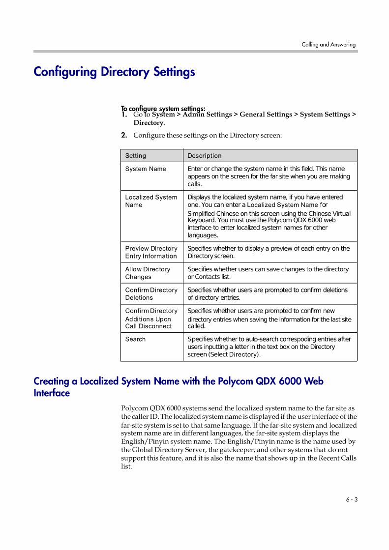
7/16/2019 QDX 6000 System Administrator Guide
http://slidepdf.com/reader/full/qdx-6000-system-administrator-guide 59/126
Calling and Answering
6 - 3
Configuring Directory Settings
To configure system settings:1. Go to System > Admin Settings > General Settings > System Settings >
Directory.
2. Configure these settings on the Directory screen:
Creating a Localized System Name with the Polycom QDX 6000 WebInterface
Polycom QDX 6000 systems send the localized system name to the far site asthe caller ID. The localized system name is displayed if the user interface of the
far-site system is set to that same language. If the far-site system and localizedsystem name are in different languages, the far-site system displays theEnglish/Pinyin system name. The English/Pinyin name is the name used bythe Global Directory Server, the gatekeeper, and other systems that do notsupport this feature, and it is also the name that shows up in the Recent Callslist.
Setting Description
System Name Enter or change the system name in this field. This nameappears on the screen for the far site when you are makingcalls.
Localized System
Name
Displays the localized system name, if you have enteredone. You can enter a Localized System Name for
Simplified Chinese on this screen using the Chinese VirtualKeyboard. You must use the Polycom QDX 6000 webinterface to enter localized system names for otherlanguages.
Preview Directory
Entry Information
Specifies whether to display a preview of each entry on theDirectory screen.
Al low Directory
Changes
Specifies whether users can save changes to the directoryor Contacts list.
Confirm Directory
Deletions
Specifies whether users are prompted to confirm deletionsof directory entries.
Confirm Directory
Addi tions UponCall Disconnect
Specifies whether users are prompted to confirm new
directory entries when saving the information for the last sitecalled.
Search Specifies whether to auto-search correspoding entries afterusers inputting a letter in the text box on the Directoryscreen (Select Directory).

7/16/2019 QDX 6000 System Administrator Guide
http://slidepdf.com/reader/full/qdx-6000-system-administrator-guide 60/126
Administrator Guide for Polycom QDX 6000 System
6 - 4
To create a localized system name using the Polycom QDX 6000 web interface:
1. On a computer, open a web browser.
2. In the browser address line, enter the system’s IP address, for example,
ht t p: / / 10. 11. 12. 13, to go to the Polycom QDX 6000 web interface.3. Go to Admin Settings > General Settings > System Settings.
4. Enter the localized system name in the appropriate language field.
Managing Directories with the Polycom QDX 6000 Web Interface
The Polycom QDX 6000 Web Interface import/export directory feature allowsyou to maintain consistency of Polycom QDX 6000 system directories in yourorganization efficiently. It is particularly useful for administrators managingmultiple systems that call the same locations. You can:
• Transfer existing directory entries between Polycom QDX 6000 systems• Develop directory entries on one system, save them to your computer, and
then distribute them to other systems
• Create localized directory entries
Only local directories can be downloaded. The directory file is in .csv format.
To download a Polycom QDX 6000 system directory to your computer:
1. On a computer, open a web browser.
2. In the browser address line, enter the system’s IP address, for example,
ht t p: / / 10. 11. 12. 13, to go to the Polycom QDX 6000 web interface.3. Go to Utilities > Import/Export Directory.
4. Click QDX 6000—> PC to download the .csv file from the Polycom QDX6000 system.
5. Save the file to a location on your computer.
To upload Polycom QDX 6000 system directory entries:
1. On a computer, open a web browser.
2. In the browser address line, enter the system’s IP address, for example,ht t p: / / 10. 11. 12. 13
, to go to the Polycom QDX 6000 web interface.3. Go to Utilities > Import/Export Directory.
4. Click PC —> QDX 6000.
5. Click Browse and browse to the location of the .csv file on your computer.
6. Click Import Directory to upload the .csv file to the Polycom QDX 6000system.

7/16/2019 QDX 6000 System Administrator Guide
http://slidepdf.com/reader/full/qdx-6000-system-administrator-guide 61/126
Calling and Answering
6 - 5
To create a localized directory entry using the Polycom QDX 6000 web interface:
1. On a computer, open a web browser.
2. In the browser address line, enter the system’s IP address, for example,
ht t p: / / 10. 11. 12. 13, to go to the Polycom QDX 6000 web interface.3. Go to Place a Call > Directory.
Edit an entry to enter a localized directory entry name in the Localized Name field, and specify the language for the localized directory entry.
Configuring the Global Directory The global directory provides a list of other systems that are registered withthe Global Directory Server and available for calls. The other systems appearin the directory, allowing users to place calls to other users by selecting theirnames.
You can configure the system to use one of the following directory servers.
Directory
Servers
Supported
Authent ication
Protocols
Global
Directory
Groups Entry Calling Information
Polycom GDS Proprietary Not Supported May include: H.323 IPaddress (raw IP address,DNS name, or H.323extension)
LDAP withH.350 orActiveDirectory
Any of thefollowing:
• NTLM
• Basic
• Anonymous
Not Supported May include:
• H.323 IP address (rawIP address, DNSname, H.323 dialeddigits, H.323 ID, orH.323 extension)
• SIP address (SIP URI)
LDAP by aPolycom CMAsystem
NTLM only Pre-definedgroups fromthe LDAPdirectory areshown inPolycom QDX
6000 system’sdirectory
May include: H.323 dialeddigits, H.323 ID, or H.323extension

7/16/2019 QDX 6000 System Administrator Guide
http://slidepdf.com/reader/full/qdx-6000-system-administrator-guide 62/126
Administrator Guide for Polycom QDX 6000 System
6 - 6
To choose a directory server:
1. Go to System > Admin Settings > Global Services > Directory Servers .
2. Enable LDAP or Polycom GDS.
3. Select Edit to edit the connection information for the desired server.
To configure the Polycom GDS settings:
1. Go to System > Admin Settings > Global Services > Directory Servers >Edit.
2. Configure these settings on the Global Directory Servers screen:
To configure the LDAP settings:
1. Go to System > Admin Settings > Global Services > Directory Servers >Edit.
2. Configure these settings on the LDAP screen.
Setting Description
Global Directory
(GDS)
Specifies the IP address or DNS address of the GlobalDirectory Server. You can enter up to five addresses.
Password Lets you enter the global directory password, if there is one.
Register Registers this system with the Global Directory Server.
Display Global
Addresses
Displays other registered systems in the global directory.
Display Name in
Global Directory
Specifies whether to display the system’s name in the globaldirectories of other registered systems.
Save Global
Directory to
System
Copies the global directory to this local system. When thissetting is disabled, the system can display no more than 1,000global directory entries. When this setting is enabled, thesystem can display up to 2,500 global directory entries.
Group Name Specifies the group name used for Polycom GDS directoryentries in the local directory. The default name for the PolycomGDS group is Polycom GDS.
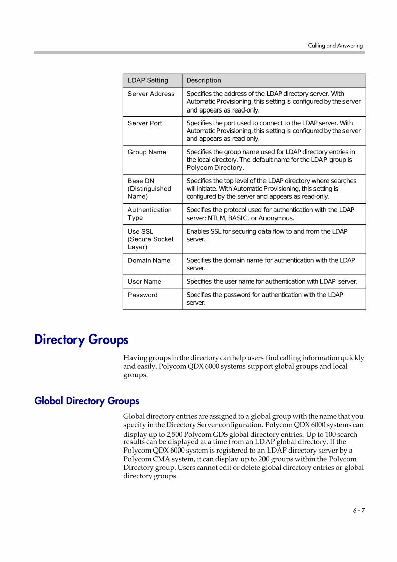
7/16/2019 QDX 6000 System Administrator Guide
http://slidepdf.com/reader/full/qdx-6000-system-administrator-guide 63/126
Calling and Answering
6 - 7
Directory GroupsHaving groups in the directory can help users find calling information quicklyand easily. Polycom QDX 6000 systems support global groups and localgroups.
Global Directory Groups
Global directory entries are assigned to a global group with the name that youspecify in the Directory Server configuration. Polycom QDX 6000 systems can
display up to 2,500 Polycom GDS global directory entries. Up to 100 searchresults can be displayed at a time from an LDAP global directory. If thePolycom QDX 6000 system is registered to an LDAP directory server by aPolycom CMA system, it can display up to 200 groups within the PolycomDirectory group. Users cannot edit or delete global directory entries or globaldirectory groups.
LDAP Setting Description
Server Address Specifies the address of the LDAP directory server. WithAutomatic Provisioning, this setting is configured by the server
and appears as read-only.
Server Port Specifies the port used to connect to the LDAP server. WithAutomatic Provisioning, this setting is configured by the serverand appears as read-only.
Group Name Specifies the group name used for LDAP directory entries inthe local directory. The default name for the LDAP group isPolycom Directory.
Base DN
(Distinguished
Name)
Specifies the top level of the LDAP directory where searcheswill initiate. With Automatic Provisioning, this setting isconfigured by the server and appears as read-only.
Authent ication
Type
Specifies the protocol used for authentication with the LDAP
server: NTLM, BASIC, or Anonymous.
Use SSL
(Secure Socket
Layer)
Enables SSL for securing data flow to and from the LDAPserver.
Domain Name Specifies the domain name for authentication with the LDAPserver.
User Name Specifies the user name for authentication with LDAP server.
Password Specifies the password for authentication with the LDAPserver.

7/16/2019 QDX 6000 System Administrator Guide
http://slidepdf.com/reader/full/qdx-6000-system-administrator-guide 64/126
Administrator Guide for Polycom QDX 6000 System
6 - 8
Local Directory Groups
The Contacts group is a local directory group that contains the types ofContacts shown in the following table. Contacts are also displayed on the
Contacts home screen.
Users can create, edit, and delete local directory entries and local directorygroups.
Directory Server
Registration Types of Contacts Presence State Displayed
Polycom GDS Directory entries created locally by the user Unknown
• Polycom GDS directory entries saved locallyas Contacts by the user
• Speed dial or sites added from the Sitesscreen
Online/Offline
LDAP with H.350 or ActiveDirectory
• Directory entries created locally by the user
• LDAP directory entries saved locally as
Contacts by the user
• Speed dial or sites added from the Sitesscreen
Unknown
LDAP by a Polycom CMASystem
• Directory entries created locally by the user
• LDAP directory entries saved locally asContacts by the user
• Default LDAP group members created in theLDAP server by the server administrator
Unknown

7/16/2019 QDX 6000 System Administrator Guide
http://slidepdf.com/reader/full/qdx-6000-system-administrator-guide 65/126
7 - 1
7
System Location, Appearance, andTones
Configuring Regional SettingsTo configure country, language, and Iong-distance dialing, go to System > Admin Settings > General Settings > Location. For more information abouteach setting, highlight the setting and press Help on the remote control.
To set the date, time, and location:
1. Go to System > Admin Settings > Location.
2. Select and configure these settings on the Time Zone screen:
Setting Description
Auto Adjust for
Daylight Saving
Time
Specifies the daylight savings time setting. When you enablethis setting, the system clock automatically changes fordaylight saving time.
Time Zone Specifies the time difference between GMT (GreenwichMean Time) and your location.
Time Server Specifies connection to a time server for automatic systemtime settings.
The date and time must be manually reset every time aPolycom QDX 6000 systemrestarts, in the following cases:
• Time Server is set to Off
• Time Server is set to Manual or Auto , but the system
cannot connect to a time server successfully.
Time Server
Address
Specifies the address of the time server to use when Time
Server is set to Manual.
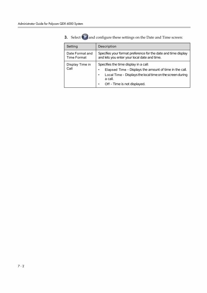
7/16/2019 QDX 6000 System Administrator Guide
http://slidepdf.com/reader/full/qdx-6000-system-administrator-guide 66/126
Administrator Guide for Polycom QDX 6000 System
7 - 2
3. Select and configure these settings on the Date and Time screen:
Setting Description
Date Format and
Time Format
Specifies your format preference for the date and time displayand lets you enter your local date and time.
Display Time in
Call
Specifies the time display in a call:
• Elapsed Time – Displays the amount of time in the call.
• Local Time – Displays the local time on the screen duringa call.
• Off – Time is not displayed.

7/16/2019 QDX 6000 System Administrator Guide
http://slidepdf.com/reader/full/qdx-6000-system-administrator-guide 67/126
System Location, Appearance, and Tones
7 - 3
Customizing the Home Screen
Customize t e system unctionaity accor ing to your users’ nee s, s i eves, an environments.
Advanced Users
Provide additional options for advancedvideo conferencing users:
• Call Quality (bandwidth and call type)
• User Settings, Diagnostics, and
System Information• Speed Dial list of frequently called
sites
• Alerts
New Users
Provide more options but keep it simple:
• Dialing entry field
• Directory numbers
• Recent Calls
Infrequent Users (Kiosk Mode)
Provide a simple workspace so no trainingis needed:
• Access to pre-defined numbers withone button click
• Instructions on screen
Use the marquee to addinstructions
Add features for usersas needed
Add more features asusers gain experience
Include a short list of specific items for users toselect
Users with Personal Systems
Provide options for personalizing thesystem:
• Access to frequently called Contactswith one button click
• Presence information for Contacts
• Availability Control
Enable the Availability
Control
Enable Contact List asHome Screen
Disable Allow DirectoryChanges
Disable Contacts List asHome Screen

7/16/2019 QDX 6000 System Administrator Guide
http://slidepdf.com/reader/full/qdx-6000-system-administrator-guide 68/126
Administrator Guide for Polycom QDX 6000 System
7 - 4
To design the home screen:
1. Go to System > Admin Settings > General Settings > Home ScreenSettings.
2. Configure these settings on the Home Screen Settings screen:
Setting Description
Dialing Display Specifies which dialing option to display:
• Dial ing en try fi el d — Allows users to enter numbersmanually.
• Display marquee — Displays text in the dialing entry field.Can be used to display user instructions. Users cannotenter numbers manually when this option is selected.
• None — Removes the dialing entry field from the screen.
Enter Marquee
Text
Specifies the text to display when the Dialing Display is set to
Display marquee.
Contact List as
Home Screen
Specifies whether to display the contact list home screen.
Call Quality Allows users to select the bandwidth for calls, as well as thecall type, from the Place a Call screen. For information aboutenabling call types, refer to Configuring Call Preferences onpage 2-13.
H.323 Extension
(E.164)
Allows users to enter H.323 extensions separately from thegateway ID on the Place a Call screen. If your system isregistered with a gatekeeper, this setting also displays yourH.323 extension on the home screen.
If you do not select this setting, users make gateway calls byentering the call information in this format:
gateway ID +##+extension
Directory Allows users to access the directory.
System Allows users to access the System screen, which includesUser Settings, Diagnostics, and System Information. If youremove the System button, you can still access the Systemscreen by navigating to the home screen, pressing on theremote, and selecting System.

7/16/2019 QDX 6000 System Administrator Guide
http://slidepdf.com/reader/full/qdx-6000-system-administrator-guide 69/126
System Location, Appearance, and Tones
7 - 5
3. Select and configure these settings:
4. Select and configure these settings:
Displaying Contacts and Speed Dial Sites
Contacts are displayed on the Contacts home screen when the Contact List asHome Screen setting is enabled. Sites configured for speed dial are displayedon the Place a Call screen when the Sites setting is enabled. Directory entriesadded to the speed dial list are also added to the Contacts list. Directory entriesadded to the Contacts list are also added to the speed dial list, except forentries stored by the presence service.
To configure speed dial sites:
1. Make sure that the site information is entered in the directory.
Setting Description
System Name Specifies whether to display the name of the system on thehome screen above the PIP window.
Local Date and
Time
Specifies whether to display the local date and time on thehome screen.
Availabi li ty
Control
Displays a control on the home screen that allows users to setthe system to Avai lable orBusy.
Call Detail
Report
Specifies whether to generate a report of all calls made with thesystem. When selected, all calls can be viewed through thePolycom QDX 6000 web interface and downloaded as a .csvfile.
Note: If this setting is disabled, applications such as thePolycom Global Management System will not be able toretrieve Call Detail Report (CDR) records.
Recent Calls Specifies whether to display the Recent Calls button on thehome screen. The Recent Calls screen lists the site number orname, the date and time, and whether the call was incoming oroutgoing.
Note: If the Call Detail Report option is not selected, theRecent Calls option is not available.
Setting Description
Sites Allows users to call any pre-defined sites from a Sites or SpeedDial list on the Place a Call screen.
Last Number
Dialed
Specifies whether to display the last number dialed or clear thedialing field on the home screen.

7/16/2019 QDX 6000 System Administrator Guide
http://slidepdf.com/reader/full/qdx-6000-system-administrator-guide 70/126
Administrator Guide for Polycom QDX 6000 System
7 - 6
2. Go to System > Admin Settings > General Settings > Home ScreenSettings.
3. Select two times and enable Sites.
4. Select to access the Sites screen.
5. Select Add and choose the sites to add from the directory.
6. Select either Speed Dial or Sites as the name you want to appear on thebutton.
To display Contacts on the Contacts home screen:
1. Go to System > Admin Settings > General Settings > Home ScreenSettings.
2. Select Contact List as Home Screen.
Adding Marquee Text
You can create marquee text to display in the dialing entry field on the homescreen. You can create context-specific instructions for your users or, if thehome screen has Site buttons, the marquee text can provide information thathelps users choose which site to call.
To enter marquee text in the Polycom QDX 6000 systeminterface:
1. Go to System > Admin Settings > General Settings > Home ScreenSettings.
2. In Dialing Display, select Display marquee and enter the text.
You can also add marquee text through the Polycom QDX 6000 web interface.For some languages such as Russian, Korean, Japanese, Simplified Chinese,and Traditional Chinese, you must use the Polycom QDX 6000 web interfaceto add marquee text.
To enter marquee text using the Polycom QDX 6000 web interface:
1. On a computer, open a web browser.
2. In the browser address line, enter the system’s IP address, for example,ht t p: / / 10. 11. 12. 13, to go to the Polycom QDX 6000 web interface.
3. Enter the user name and administrator’s password, if a password hasbeen established.
4. Click Admin Settings > General Settings > Home Screen Settings andenter.

7/16/2019 QDX 6000 System Administrator Guide
http://slidepdf.com/reader/full/qdx-6000-system-administrator-guide 71/126
System Location, Appearance, and Tones
7 - 7
— Dialing Display— Set to Display marquee.
— Enter Marquee Text — Type the text to display on the home screen.
5. Click Update.
Setting Ring Tones and Alert Tones
To set ring tones and aler t tones:
1. Go to System > Admin Settings > Audio > Audio Settings.
2. Select a tone, as desired.
Customizing Camera Names and IconsCustomizing the way cameras appear on screen helps users select the correctcamera input during a call. You can enter camera names and assign icons. Youcan choose camera icons from categories including Corporate, Education,
Justice, Manufacturing, and Medical.
To customize camera names and icons:
1. Go to System > Admin Settings > Cameras.
2.For each camera or video source, enter a name and choose an icon.
Screen SaversFor information about setting the Screen Saver Wait Time, refer to page 3-3.
Adding Screen Saver Text
You can customize the Polycom QDX 6000 system to display text when thesystem is in sleep mode. For instance, you can display on-screen instructions
to assist users with what steps they should take next.
Output upon Screen Saver Activation on the Monitors screen must be set toBlack if you want to display screen saver text.

7/16/2019 QDX 6000 System Administrator Guide
http://slidepdf.com/reader/full/qdx-6000-system-administrator-guide 72/126
Administrator Guide for Polycom QDX 6000 System
7 - 8
To enter screen saver text:
1. On a computer, open a web browser.
2. In the browser address line, enter the system’s IP address, for example,
ht t p: / / 10. 11. 12. 13, to go to the Polycom QDX 6000 web interface.3. Enter the user name and administrator’s password, if a password has
been established.
4. Click Utilities > Screen Saver and enter:
— Screen Saver Text — Appears as scrolling text when the system is insleep mode. You can use this scrolling text to provide instructions ornext steps for users of the system.
— Logo Screen Text — Appears underneath the logo before the systemgoes into sleep mode.
5. Click Update.
Customizing System LogosYou can customize the following logos shown on your Polycom QDX 6000system in the on screen UI and the web interface:
• Screen Saver Logo
• Web Welcome Logo
• Splash Logo
• Embedded UI Logo
• Web Header Logo
Adding a Screen Saver Logo
You can customize the Polycom QDX 6000 system to display your own screensaver logo instead of the Polycom logo.
To upload a screen saver logo:
1. On a computer, open a web browser.
2. In the browser address line, enter the system’s IP address, for example,ht t p: / / 10. 11. 12. 13, to go to the Polycom QDX 6000 web interface.
3. Enter the user name and administrator’s password, if a password hasbeen established.
4. Click Utilities > Screen Saver, click Next, and follow the onscreeninstructions for uploading a logo file.

7/16/2019 QDX 6000 System Administrator Guide
http://slidepdf.com/reader/full/qdx-6000-system-administrator-guide 73/126
System Location, Appearance, and Tones
7 - 9
Adding a Web Welcome Logo
You can customize the Polycom QDX 6000 system to display your own webwelcome logo instead of the Polycom logo.
To upload a web welcome logo:
1. On a computer, open a web browser.
2. In the browser address line, enter the system’s IP address, for example,ht t p: / / 10. 11. 12. 13, to go to the Polycom QDX 6000 web interface.
3. Enter the user name and administrator’s password, if a password hasbeen established.
4. Click Utilities > Customise System Logo > Web Welcome Logo, andfollow the onscreen instructions for uploading a logo file.
Adding a Splash Logo
You can customize the Polycom QDX 6000 system to display your own splashlogo instead of the Polycom logo.
To upload a splash logo:
1. On a computer, open a web browser.
2. In the browser address line, enter the system’s IP address, for example,ht t p: / / 10. 11. 12. 13, to go to the Polycom QDX 6000 web interface.
3. Enter the user name and administrator’s password, if a password hasbeen established.
4. Click Utilities > Customise System Logo > Splash Logo, and follow theonscreen instructions for uploading a logo file.
Adding an Embedded UI Logo
You can customize the Polycom QDX 6000 system to display your ownembedded UI logo instead of the Polycom logo.
To upload an embedded UI logo:
1. On a computer, open a web browser.
2. In the browser address line, enter the system’s IP address, for example,ht t p: / / 10. 11. 12. 13, to go to the Polycom QDX 6000 web interface.
3. Enter the user name and administrator’s password, if a password hasbeen established.

7/16/2019 QDX 6000 System Administrator Guide
http://slidepdf.com/reader/full/qdx-6000-system-administrator-guide 74/126
Administrator Guide for Polycom QDX 6000 System
7 - 10
4. Click Utilities > Customise System Logo > Embedded UI Logo, andfollow the onscreen instructions for uploading a logo file.
Adding a Web Header LogoYou can customize the Polycom QDX 6000 system to display your own webheader logo instead of the Polycom logo.
To upload a web header logo:
1. On a computer, open a web browser.
2. In the browser address line, enter the system’s IP address, for example,ht t p: / / 10. 11. 12. 13, to go to the Polycom QDX 6000 web interface.
3. Enter the user name and administrator’s password, if a password hasbeen established.
4. Click Utilities > Customise System Logo > Web Header Logo, andfollow the onscreen instructions for uploading a logo file.
Restoring the Default Logos
To restore the default logos:
1. On a computer, open a web browser.
2. In the browser address line, enter the system’s IP address, for example,
ht t p: / / 10. 11. 12. 13, to go to the Polycom QDX 6000 web interface.3. Enter the user name and administrator’s password, if a password has
been established.
4. Do the following,
— If you want to restore the screen saver logo, click Utilities > ScreenSaver, click Next, and click .
— If you want to restore the web welcome logo, click Utilities >Customise System Logo > Web Welcome Logo , and click .
— If you want to restore the splash logo, click Utilities > CustomiseSystem Logo > Splash Logo, and click .
— If you want to restore the embedded UI logo, click Utilities >Customise System Logo > Embedded UI Logo, and click .
— If you want to restore the web header logo, click Utilities > CustomiseSystem Logo > Web Header Logo, and click .

7/16/2019 QDX 6000 System Administrator Guide
http://slidepdf.com/reader/full/qdx-6000-system-administrator-guide 75/126
8 - 1
8
Security
Screens that Require a Password for AccessYou can configure Polycom QDX 6000 systems to provide two levels of accessfor people who are in the room with the system. You can require a user login
to use the system. In addition, you can require an administrator login toconfigure system Admin Settings.
The following illustration shows which screens could require a user login andwhich screens could require an administrator login.
You can set a remote access password to restrict who can upgrade the PolycomQDX 6000 system software or perform other remote management from acomputer.
Diagnostics* System Information User SettingsUtilities
Could Require Administrator Login
Could Require User Login
*Reset System is password-protectedwhen Security Mode is enabled
Contacts/Place a Call Recent Calls Directory
Admin Settings
General Settings Network LAN PropertiesAudio Global ServicesCamerasMonitors

7/16/2019 QDX 6000 System Administrator Guide
http://slidepdf.com/reader/full/qdx-6000-system-administrator-guide 76/126
Administrator Guide for Polycom QDX 6000 System
8 - 2
Configuring Security Options
To set passwords and security options:1. Go to System > Admin Settings > General Settings > Security >
Security Settings.
2. Configure these settings on the Security screen:
Setting Description
Security Mode Specifies whether the system uses Security Mode, whichprevents unsecured access to the system. Every time youenable Security Mode, you must configure a new passwordfor the system.
Security Profile If set to DoD DSN, the Security Profile sets and controls
particular security settings in order to meet DoD DSNrequirements. This setting is visible only if the SecurityProfile was configured in the setup wizard.
Use Room
Password for
Remote Access
Specifies whether the room password used for local login isalso used for the remote login.
Admin ID Specifies the ID for the administrator account.
Room Password Specifies the password for administrator access whenlogging in to the system locally.
When the room password is set, you must enter it toconfigure the system Admin Settings using the remote
control. The room password must not contain spaces.
Remote Access
Password
Specifies the password for administrator access whenlogging in to the system remotely.
When the remote access password is set, you must enter itto upgrade the software or manage the system from acomputer. The remote access password must not containspaces.

7/16/2019 QDX 6000 System Administrator Guide
http://slidepdf.com/reader/full/qdx-6000-system-administrator-guide 77/126
Security
8 - 3
3. Select and configure these settings:
4. Select and configure these settings:
Setting Description
Require Login for System Access
Specifies whether the system automatically promptsusers to log in when the system comes out of sleepmode. Enabling this setting requires a login to usethe system.
User ID Specifies the ID for the user account.
User Password Specifies the password for the user account. Toenter numbers, use the number buttons on the
remote or keypad. To enter letters, press
Keyboard on the remote or keypad.
Setting Description
Enable Remote
Access
Specifies whether to allow remote access to the system by:
• Web
• Telnet
• SNMP
You may select any of these, or any combination of them.
Note: The system restarts if you change the remote accesssettings. This setting does not deactivate the associatedport, only the application. Use Web Access Port to disablethe port.
AES Encrypt ion Specifies how to encrypt calls with other sites that supportAES encryption.
• Off —AES Encryption is disabled.
• When Available—AES Encryption is used with anyendpoint that supports it, even if the other endpoints inthe call don’t support it.
• Requi red for A ll Cal ls—AES Encryption is used for allvideo endpoints in the call. All endpoints must supportAES Encryption to participate in the call.

7/16/2019 QDX 6000 System Administrator Guide
http://slidepdf.com/reader/full/qdx-6000-system-administrator-guide 78/126
Administrator Guide for Polycom QDX 6000 System
8 - 4
5. Select and configure this setting:
Configuring Security ModeYou can configure Polycom QDX 6000 systems to use Security Mode, which
provides secure access to the system. Security Mode utilizes TLS, HTTPS, AES,digital signatures, and other security protocols, algorithms, and mechanismsto put the system into a secure mode. These protocols encrypt managementcommunication over IP, preventing access by unauthorized users.
Every time you enable Security Mode, you must configure a new password forthe system. The password cannot be blank and it cannot be the default value(serial number).
Al low Video
Display on Web
Specifies whether to allow viewing of the room where thesystem is located, or video of calls in which the system
participates, using the Polycom QDX 6000 web interface.Note: This feature activates both near site and far site videodisplays in Web Director.
Web Access Port
(http)
Specifies the port to use when accessing the system usingthe Polycom QDX 6000 web interface.
If you change this from the default (port 80), specify a portnumber of 1025 or higher, and make sure the port is notalready in use. You will need to include the port number withthe IP address when you use the Polycom QDX 6000 webinterface to access the system. This makes unauthorizedaccess more difficult.
Note: The system restarts if you change the web accessport.
Al low Access to
User Settings
Specifies whether the User Settings screen is accessible tousers via the System screen.
Select this option if you want to allow users to changelimited environmental settings.
Setting Description
Setting Description
Enable Securit y
Banner
Specifies the security banner to display when the systemwakes up or a user logs in.
• Off — Disables the security banner.• Custom — Allows you to enter text to use for the banner.
You can enter up to ten lines of text, each of which cancontain up to 128 single-byte characters.
• DoD — Specifies that the system displays a default U.S.Department of Defense security banner.

7/16/2019 QDX 6000 System Administrator Guide
http://slidepdf.com/reader/full/qdx-6000-system-administrator-guide 79/126
Security
8 - 5
Security Mode requires secure access and a password for Web access.
When you enable Security Mode, the following settings are set and controlledby the system:
To configure the system to use Security Mode:
1. Go to System > Admin Settings > General Settings > Security >Security Settings.
2. Enable Security Mode.
When you change this setting, the Polycom QDX 6000 system restarts. Everytime a Polycom QDX 6000 system is powered on or restarts in Security Mode,it verifies that the system software is authentic Polycom software.
Setting Restriction
AES Encrypt ion Set to Required for Video Calls Only (or When
Available after an upgrade), configurable
Enable Remote
Access : Telnet
Disabled for port 23 and 24, read-only
Enable Remote
Access: SNMP
Disabled, read-only
Web Access Port Port 80 disabled with no redirect to port 443, read-only
Port 443: Available for HTTPS, read-only
Al low Video Displayon Web
Disabled, configurable
Auto Answer
Settings
Auto Answer Point-to-Point: Disabled, configurable
User Settings Mute Auto-Answer Calls: Hidden
Allow Video Display on Web: Hidden
Far Control of Near Camera: Hidden
Minimum Password
Length
Set to 1, must be at least 1

7/16/2019 QDX 6000 System Administrator Guide
http://slidepdf.com/reader/full/qdx-6000-system-administrator-guide 80/126
Administrator Guide for Polycom QDX 6000 System
8 - 6
To access a Polycom QDX 6000 system in Security Mode using the Polycom QDX 6000 web interface:
1. Enter the IP address of the system using secure HTTPS access, forexample, ht t ps: / / 10. 11. 12. 13.
2. Click Yes in the security dialogs that appear. This access uses port 443.
3. To access Admin Settings using the Polycom QDX 6000 web interfacewhen a remote access password is set, enter the administrator account (“admin” is default).
Enabling a Security Profile
You can configure a Security Profile in the setup wizard only. If set to DoDDSN, the Security Profile sets and controls particular security settings in order
to meet DoD DSN requirements. For a list of pre-defined values and additionalrestrictions applied by the Security Profile, refer to the U.S. DoD DSN Deployment Guide available on the Polycom web site.
To enable a Security Profile:
In the setup wizard, enable Security Mode and set Security Profile toDoD DSN.
To view the Security Profile setting:
Go to System > Admin Settings > General Settings > Security > SecuritySettings.
If you do not see the Security Profile setting, it is set to None and nosettings are controlled by the Security Profile.
Points to note about Security Mode:
• SNMP access is not available in Security Mode.
• Global Management System, ReadiManager SE200, and Polycom CMA
systems cannot monitor Polycom QDX 6000 systems in Security Mode.• If Security Mode is enabled, you must enter the room password to reset the
system (System > Diagnostics > Reset System). If you forget the roompassword while the system is in Security Mode, refer to Using the RestoreButton on page 12-2.
• The web interface allows only HTTPS connections using TLS when SecurityMode is enabled. Make sure that your web browser has TLS capabilitiesenabled.

7/16/2019 QDX 6000 System Administrator Guide
http://slidepdf.com/reader/full/qdx-6000-system-administrator-guide 81/126
Security
8 - 7
Enabling AES EncryptionAES encryption is a standard feature on all Polycom QDX 6000 systems. Whenit is enabled, the system automatically encrypts calls to other systems that have
AES encryption enabled.
To enable AES encryption:
Go to System > Admin Settings > General Settings > Security > SecuritySettings > > and set AES Encryption.
Setting Password PoliciesThis version allows you to set up password policies, which are requirementsthat must be met when creating new passwords. These password settings canensure that strong passwords are used.
To configure password policies:
1. Go to System > Admin Settings > General Settings > Security >
Password Settings in the local system interface.2. Select Room, User, or Remote Access.
3. Configure these settings:
Points to note about AES Encryption:
• AES Encryption is not supported in Basic Mode.
• AES Encryption is not supported on systems registered to an Avaya H.323gatekeeper.
When Use Room Password for Remote Access is enabled, the room passwordpolicy is applied to both room and remote access passwords.
Setting Description
Minimum Length Specifies the minimum number of characters required for a
valid password.
Can Contain ID or
Its Reverse Form
Specifies whether the associated ID or the reverse of the IDcan be part of a valid password. If this setting is enabled andthe ID is “admin”, passwords “admin” and “nimda” areallowed.

7/16/2019 QDX 6000 System Administrator Guide
http://slidepdf.com/reader/full/qdx-6000-system-administrator-guide 82/126
Administrator Guide for Polycom QDX 6000 System
8 - 8
4. Select and configure these settings:
Setting the Room and Remote Access PasswordsYou can set the room password to restrict who can configure system AdminSettings using the remote control. You can set the remote access password torestrict who can upgrade the Polycom QDX 6000 system software or performother remote management from a computer.
Require Lower
Case Letters
Specifies whether a valid password must contain one ormore lower-case letters.
Require Upper
Case Letters
Specifies whether a valid password must contain one ormore upper-case letters.
Require Numbers Specifies whether a valid password must contain one ormore numbers.
Require Special
Characters
Specifies whether a valid password must contain one ormore special characters. Supported characters include:@ - _ ! ; $ , \ / & . #*
Setting Description
Setting Description
Do Not Allow
Previous
Passwords
Specifies the number of most recent passwords that cannotbe reused. If set to Off , all previous passwords can bereused.
Minimum
Password Age in
Days
Specifies the minimum number of days that must passbefore the password can change.
Maximum
Password Age in
Days
Specifies the maximum number of days that can pass beforethe password must change.
Password
Expiration
Warning in Days
Specifies how far in advance the system displays a warningthat the password will soon expire, if a maximum passwordage is set.
Minimum
Changed
Characters
Specifies the number of characters that must be different orchange position in a new password. If this is set to 3,“123abc” can change to “345cde”, or to “234bcd”.
Maximum
Consecutive
Repeated
Characters
Specifies the maximum number of consecutive repeatedcharacters in a valid password. If this is set to 3, “aaa123” isa valid password but “aaaa123” is not.
7/16/2019 QDX 6000 System Administrator Guide
http://slidepdf.com/reader/full/qdx-6000-system-administrator-guide 83/126
Security
8 - 9
All passwords appear as a series of asterisks as you type them in aconfiguration or login screen. To enter numbers in a password field, use theremote or keypad number buttons. To enter letters in a password field, press
Keyboard on the remote or keypad.
To set or change the room password:
1. Go to System > Admin Settings > General Settings > Security >Security Settings.
2. Enter or change the password.
The default room password is the 16-digit system serial number.
To set or change the remote access password:
1. Go to System > Admin Settings > General Settings > Security >
Security Settings.
2. Clear the Use Room Password for Remote Access setting if it is selected.By default, the remote access password is the same as the roompassword.
3. Enter a Remote Access password.
To use the same password for both local and remote access:
1. Go to System > Admin Settings > General Settings > Security >Security Settings.
2. Select Use Room Password for Remote Access.
To reset a forgotten password:
1. Get the system’s serial number from the system or from the SystemInformation screen.
2. Go to System >Diagnostics > Reset System.
3. Enter the system’s serial number and select Delete System Settings.
4. Select Reset System.
After the system resets, it leads you through the setup wizard. You can enter anew password when you set up the system.
If Security Mode is enabled, the room password is required to access the ResetSystem screen. If you forget the room password while the system is in SecurityMode, refer to Using the Restore Button on page 12-2.

7/16/2019 QDX 6000 System Administrator Guide
http://slidepdf.com/reader/full/qdx-6000-system-administrator-guide 84/126
Administrator Guide for Polycom QDX 6000 System
8 - 10
Setting an Account Lockout You can configure and enforce an account lockout if someone fails to log incorrectly. After a certain number of failed login attempts, the account is locked
for an amount of time specified by the administrator.
To configure the account lockout feature:
1. Go to System > Admin Settings > General Settings > Security >Account Management.
2. Select Admin Account or User Account.
3. Configure these settings on the Admin Account or User Account screen:
Managing User Access to Settings and FeaturesYou can manage user access to settings and features by using passwords and
by configuring the system to show only those options you want your users tosee.
Setting Description
Lock Account after Failed Logins
Specifies the number of failed login attempts allowed beforethe system locks the account. If set to Off , the system willnot lock the user account due to failed login attempts.
Account Lock
Duration in
Minutes
Specifies the amount of time that the account remainslocked due to failed login attempts.
Security Level Restrictions
High
(Kiosk mode)
An administrator login is required to configure systemAdmin Settings. Users can call only the numbers youspecify on the home screen.
See Customizing the Home Screen on page 7-3.
High
(User login mode)
An administrator login is required to configure systemAdmin Settings. A user login is required to use the system.

7/16/2019 QDX 6000 System Administrator Guide
http://slidepdf.com/reader/full/qdx-6000-system-administrator-guide 85/126
Security
8 - 11
You can allow users to change common user preferences by providing accessto the User Settings screen.
To allow users to customize the workspace:
1. Go to System > Admin Settings > General Settings > Security >Security Settings > > .
2. Select the Allow Access to User Settings option to make the UserSettings button available to users on the System screen.
User Settings contains the following options, which are also available toadministrators on the Admin Settings screens:
• Backlight Compensation
• Far Control of Near Camera
• Auto Answer Point-to-Point Video
• Mute Auto-Answer Calls
• PIP
• Keypad Audio Confirmation
• Far Site Name Display Time
• Allow Video Display on Web
Medium An administrator login is required to configure systemAdmin Settings. Users can place calls using the restrictions
you specify for length of call, type of call, and use of thedirectory.
Low An administrator login is required to configure systemAdmin Settings. However, Allow Access to User Settings isenabled so that users can configure some settings.
Very low No administrator login is required to configure systemAdmin Settings. Users can configure all system settings.
Security Level Restrictions

7/16/2019 QDX 6000 System Administrator Guide
http://slidepdf.com/reader/full/qdx-6000-system-administrator-guide 86/126
Administrator Guide for Polycom QDX 6000 System
8 - 12

7/16/2019 QDX 6000 System Administrator Guide
http://slidepdf.com/reader/full/qdx-6000-system-administrator-guide 87/126
9 - 1
9
Managing the System Remotely
You can configure, manage, and monitor the system from a computer usingthe system’s web interface. You can also use Polycom CMA, SNMP, or the APIcommands.
• The Polycom QDX 6000 Web Interface requires only a web browser.
• Polycom CMA requires the management application to be installed onyour network.
• SNMP requires network management software on your networkmanagement station.
• For more information about the API commands, refer to the API Reference Manual for Polycom QDX 6000 Systems.
Using the Polycom QDX 6000 Web InterfaceYou can use the Polycom QDX 6000 web interface to perform most of thecalling and configuration tasks you can perform on the local system.
Accessing the Polycom QDX 6000 Web Interface
To configure your browser to use the Polycom QDX 6000 web interface:
1. Be sure that you use Microsoft Internet Explorer 6.x, 7.x,or 8.x as yourweb browser.
2. Configure the browser to allow cookies.

7/16/2019 QDX 6000 System Administrator Guide
http://slidepdf.com/reader/full/qdx-6000-system-administrator-guide 88/126
Administrator Guide for Polycom QDX 6000 System
9 - 2
To access the system using the Polycom QDX 6000 web interface:
1. On a computer, open a web browser.
2. In the browser address line, enter the system’s host name or IP address,
for example, ht t p: / / 10. 11. 12. 13, to go to the Polycom QDX 6000 webinterface.
If Security Mode is enabled on the system, you must use secure HTTPSaccess, for example, ht t ps: / / 10. 11. 12. 13. Click Yes in the securitydialog boxes that appear.
3. If prompted, enter the administrator account ( “admin” is default), andenter the remote access password.
Monitoring a Room or Call with the Polycom QDX 6000 Web Interface
The monitoring feature within the Polycom QDX 6000 web interface allows
administrators of Polycom QDX 6000 systems to view a call or the room wherethe system is installed.
To enable room and call monitoring:
1. Go to System > Admin Settings > General Settings > Security >Security Settings.
2. Select > > and enable Allow Video Display on Web to allowthe room or call to be viewed remotely.
To view a room or call:
1. On a computer, open a web browser.
2. In the browser address line, enter the system’s IP address, for example,ht t p: / / 10. 11. 12. 13, to go to the Polycom QDX 6000 web interface.
3. Go to Utilities > Web Director.
4. Perform any of the following tasks:
— Place or end a call
— View near and far sites
— Change camera sources
— Adjust camera position— Zoom cameras
— Adjust system volume settings
— Mute and unmute the microphones
You can view near and far sites without opening Web Director by selectingTools > Remote Monitoring .

7/16/2019 QDX 6000 System Administrator Guide
http://slidepdf.com/reader/full/qdx-6000-system-administrator-guide 89/126
Managing the System Remotely
9 - 3
Managing System Profiles with the Polycom QDX 6000 Web Interface
Administrators managing systems that support multiple applications canchange system settings quickly and easily using profiles. You can store a
Polycom QDX 6000 system profile on a computer as a .profile file using thePolycom QDX 6000 web interface. There is no limit to the number of profilesyou can save.
The following settings are included in a profile:
• Home screen settings
• User access levels
• Icon selections
• Option keys
• System behaviors
Passwords are not included when you store a profile.
To store a profile:
1. On a computer, open a web browser.
2. In the browser address line, enter the system’s IP address, for example,ht t p: / / 10. 11. 12. 13, to go to the Polycom QDX 6000 web interface.
3. Go to Utilities > Profile Center.
4. Click QDX 6000—> PC to download the profile file from the PolycomQDX 6000 system.
5. Save the file to a location on your computer.
To upload a profile:
1. Reset the Polycom QDX 6000 system to restore default settings.
2. On a computer, open a web browser.
3. In the browser address line, enter the system’s IP address, for example,ht t p: / / 10. 11. 12. 13, to go to the Polycom QDX 6000 web interface.
4. Go to Utilities > Profile Center.
5. Click Browse and browse to the location of the profile file on yourcomputer.
6. Click PC —> QDX 6000 to upload the .profile file to your system.
Polycom recommends using profiles only as a way to back up system settings.Attempting to edit a stored profile or upload it to more than one system on thenetwork can result in instability or unexpected results.

7/16/2019 QDX 6000 System Administrator Guide
http://slidepdf.com/reader/full/qdx-6000-system-administrator-guide 90/126
Administrator Guide for Polycom QDX 6000 System
9 - 4
Sending a Message
If you are experiencing difficulties with connectivity or audio, you may wantto send a message to the system that you are managing.
Only the near site can see the message; it is not broadcast to all the sites in thecall.
To send a message via the Polycom QDX 6000 web interface:
1. On a computer, open a web browser.
2. In the browser address line, enter the system’s IP address, for example,ht t p: / / 10. 11. 12. 13, to go to the Polycom QDX 6000 web interface.
3. If prompted, enter the administrator account ( “admin” is default)., andenter the admin password.
4. Go to Diagnostics > Send a Message.
5. In the Send a Message page, enter a message (up to 100 characters inlength), then click Send.
The message is displayed for 15 seconds on the screen of the system thatyou are managing.
Setting Up SNMP
The Polycom QDX 6000 system sends SNMP (Simple Network ManagementProtocol) reports to indicate conditions, including the following:
• All alert conditions found on the Polycom QDX 6000 system alert page
• Details of jitter, latency, and packet loss
• Low battery power is detected in the remote control
• A system powers on
• Administrator logon is successful or unsuccessful
• A call fails for a reason other than a busy line
• A user requests help
• A telephone or video call connects or disconnects
Polycom QDX 6000 systems are compatible with SNMP versions 1 and 2c.
Downloading MIBs
In order to allow your SNMP management console application to resolveSNMP traps and display human readable text descriptions for those traps, youneed to install Polycom MIBs (Management Information Base) on thecomputer you intend to use as your network management station. The MIBsare available for download from the Polycom QDX 6000 web interface.

7/16/2019 QDX 6000 System Administrator Guide
http://slidepdf.com/reader/full/qdx-6000-system-administrator-guide 91/126
Managing the System Remotely
9 - 5
To download the Polycom MIBs:
1. On a computer, open a web browser.
2. In the browser address line, enter the IP address of the system, for
example, ht t p: / / 10. 11. 12. 13, to go to the Polycom QDX 6000 webinterface.
3. Go to Admin Settings > Global Services > SNMP.
4. Click Download MIB and follow the onscreen instructions.
Configuring for SNMP Management
To configure the Polycom QDX 6000 system for SNMP Management:
1. Access the SNMP configuration screen either in the Polycom QDX 6000web interface or on the Polycom QDX 6000 system.
— In the Polycom QDX 6000 web interface go to Admin Settings >Global Services > SNMP.
— On the Polycom QDX 6000 system go to System > Admin Settings >Global Services > SNMP.
2. Configure these settings on the SNMP screen:
Setting Description
Enable SNMP Allows administrators to manage the system remotelyusing SNMP.
Trap Version Specifies the trap protocol that the system uses.
• v2c—System uses the v2c trap.
• v1—System uses the v1 trap.
Read-Only
Community
Specifies the SNMP management community in which youwant to enable this system. The default community ispublic.
Note: Polycom does not support SNMP write operationsfor configuration and provisioning; the read-onlycommunity string is used for both read operations andoutgoing SNMP traps.
Contact Name Specifies the name of the person responsible for remotemanagement of this system.
Location Name Specifies the location of the system.
System Description Specifies the type of video conferencing device.
Console IP
Address
Specifies the IP address of the computer you intend to useas your network management station and to which SNMPtraps will be sent.

7/16/2019 QDX 6000 System Administrator Guide
http://slidepdf.com/reader/full/qdx-6000-system-administrator-guide 92/126
Administrator Guide for Polycom QDX 6000 System
9 - 6
Keeping your Software Current If you have Internet access and a software key, you can update the PolycomQDX 6000 system software. If you do not have Internet access, your reseller
can supply you with the Polycom QDX 6000 system software update onCD-ROM.
Refer to the Release Notes for Polycom QDX 6000 Systems for information aboutthe latest software version. Refer to Installing Polycom QDX 6000 Software fordetailed information about obtaining software key codes and installingsoftware upgrade.

7/16/2019 QDX 6000 System Administrator Guide
http://slidepdf.com/reader/full/qdx-6000-system-administrator-guide 93/126
10 - 1
10
Control Devices
Configuring Remote Control BehaviorYou can customize the behavior of the remote control to support the users’environment.
To configure remote control behavior:
1. Go to System > Admin Settings > General Settings > System Settings >Remote Control.
2. Configure these settings on the Remote Control screen:
Configuring RS-232 Serial Port Settings
To configure RS-232 serial port settings:
1. Go to System > Admin Settings > General Settings > Serial Ports.
2. Configure these settings for a Polycom QDX 6000 system:
Setting Description
Keypad Aud io
Confirmation
Specifies whether to play a voice confirmation of numbersselected with the remote control or keypad.
Numeric KeypadFunction
Specifies whether pressing number buttons on the remotecontrol or keypad moves the camera to presets orgenerates touch tones (DTMF tones). If this is set toPresets, users can generate DTMF tones by pressingwhile on a video screen.

7/16/2019 QDX 6000 System Administrator Guide
http://slidepdf.com/reader/full/qdx-6000-system-administrator-guide 94/126
Administrator Guide for Polycom QDX 6000 System
10 - 2
Setting Description
RS-232 Mode Specifies the mode used for the serial port.
• Off —Disables the serial port.• Control—Receives control signals from a touch-panel
control. Allows any device connected to the RS-232port to control the system using API commands.
• Pass Thru—Passes data to an RS-232 deviceconnected to the serial port of the far-site system.
Baud Rate, Parity,
Data Bits, Stop B its
Set these to the same values that they are set to on theserial device.
RS-232 Flow
Control
When a Vortex is connected to an RS-232 connector onthe Polycom QDX 6000 system, set both to Hardware.

7/16/2019 QDX 6000 System Administrator Guide
http://slidepdf.com/reader/full/qdx-6000-system-administrator-guide 95/126
11 - 1
11
Statistics and Diagnostics
The Polycom QDX 6000 system provides various screens that allow you toreview information about calls made by the system and to review networkusage and performance.
Diagnostic ScreensThe following Diagnostics screens are available on the system and in thePolycom QDX 6000 web interface.
Diagnostics
Call Statistics
Network
Video
Audio
System Status System Status
Server Status
Restart/Reset
Speaker Test
Audio Meter
Call Status
Call Statistics
Content Statistics
Call Summary
Near End Loop
PING
Trace Route
Send a Message
(web only)
System Log(web only)
Download Logs
System Log Settings
Call Summary

7/16/2019 QDX 6000 System Administrator Guide
http://slidepdf.com/reader/full/qdx-6000-system-administrator-guide 96/126
Administrator Guide for Polycom QDX 6000 System
11 - 2
To access the Diagnostics screens on the system:
Go to System > Diagnostics.
To access the Diagnostics screens from the Polycom QDX 6000 web interface:
1. On a computer, open a web browser.
2. In the browser address line, enter the system’s IP address, for example,ht t p: / / 10. 11. 12. 13, to go to the Polycom QDX 6000 web interface.
3. If prompted, enter the administrator account ( “admin” is default), andenter the admin password.
4. Click Diagnostics from any page in the Polycom QDX 6000 web interface.
System Status
Server Status
Diagnost ic Screen Descr ip tion
System Status Displays system status information, including auto-answerpoint to point, remote control battery, system serialnumber, and IP network. For an explanation of any of the
status items, select the item and press on the remote.
When there is a change in system status or a potentialproblem, you see an alert at the bottom of the homescreen.
Diagnost ic Screen Descr ip tion
Server Status Displays server status information, including time server,global directory, gatekeeper, and registrar server. For anexplanation of any of the status items, select the item and
press on the remote.
When there is a change in server status or a potentialproblem, you see an alert at the bottom of the homescreen.

7/16/2019 QDX 6000 System Administrator Guide
http://slidepdf.com/reader/full/qdx-6000-system-administrator-guide 97/126
Statistics and Diagnostics
11 - 3
Call Statistics
Diagnost ic Screen Descr ip tion
Call Statistics Displays information about the call in progress.
View Call Statistics during a call by pressing Help onthe remote.
Call Statistics (1)
• Call speed (transmit and receive)
• Video protocol, and format in use (transmit andreceive).
• Audio protocol in use (transmit and receive)
• Number of packets lost and percentage packet loss(transmit and receive) in IP calls
• Encryption type, key exchange algorithm type, and keyexchange check code (if the encryption option is
enabled and the call is encrypted)
• Far site details and call type
Call Statistics (2)
• Audio and video data rates specified (transmit andreceive)
• Video data rate and frame rate in use (transmit andreceive)
• Video packet loss and jitter in IP calls
• Audio packet loss and jitter in IP calls
• Far site details and call type
Content Statistics
The Content Statistics screen shows statistics for contentshared during a call.
Call Summary
(system only)
Displays calling information, such as:
• Duration of the last call
• Total number of IP calls
• Total time of IP calls

7/16/2019 QDX 6000 System Administrator Guide
http://slidepdf.com/reader/full/qdx-6000-system-administrator-guide 98/126
Administrator Guide for Polycom QDX 6000 System
11 - 4
Network
Video
Diagnost ic Screen Descr ip tion
Near End Loop Tests the internal audio encoders and decoders, theexternal microphones and speakers, the internal videoencoders and decoders, and the external cameras andmonitors.
Monitor 1 displays the video and plays the audio thatwould be sent to the far site in a call.
This test is not available when you are in a call.
PING Tests whether the system can establish contact with afar-site IP address that you specify.
PING returns abbreviated Internet Control MessageProtocol results. It returns H.323 information only if the farsite is configured for H.323. It returns SIP information only
if the far site is configured for SIP .If the test is successful, the Polycom QDX 6000 systemdisplays a message indicating that the IP address undertest is available.
Trace Route Tests the routing path between the local system and the IPaddress entered.
If the test is successful, the Polycom QDX 6000 systemlists the hops between the system and the IP address youentered.
Diagnost ic Screen Descr ip tion
Video Diagnostics Tests the color settings of your monitor for optimum picturequality.
If the color bars generated during the test are not clear, orthe colors do not look correct, the monitor needs to beadjusted.

7/16/2019 QDX 6000 System Administrator Guide
http://slidepdf.com/reader/full/qdx-6000-system-administrator-guide 99/126
Statistics and Diagnostics
11 - 5
Audio
Diagnost ic Screen Descr ip tion
Speaker Test Tests the audio cable connections. A 473 Hz audio toneindicates that the local audio connections are correct.
If you run the test from the system during a call, the far sitewill also hear the tone.
If you run the test from the Polycom QDX 6000 webinterface during a call, the people at the site you aretesting will hear the tone, but you will not.
Audio Meter Measures the strength of audio signals frommicrophone(s), far-site audio, VCR audio, and any deviceconnected to the audio line in.
• To check the microphone(s), speak into themicrophone.
• To check far-site audio, ask a participant at the far siteto speak or call a phone in the far-site room to hear itring.
• To check a VCR or DVD, connect it to the VCR inputsand play the VCR or DVD to test the audio.
The Audio Meters indicate peak signal levels. Set signallevels so that you see peaks between +3dB and +7dB withnormal speech and program material. Occasional peaks of +12dB to +16dB with loud transient noises are consideredacceptable. A meter reading of +20dB corresponds to0dBFS in the Polycom QDX 6000 system audio. A signalat this level is likely clipping the audio system.
Meters function only when the associated input is enabled.
Note: Some audio meters are unavailable when aSoundStructure digital mixer is connected to the PolycomQDX 6000 system.
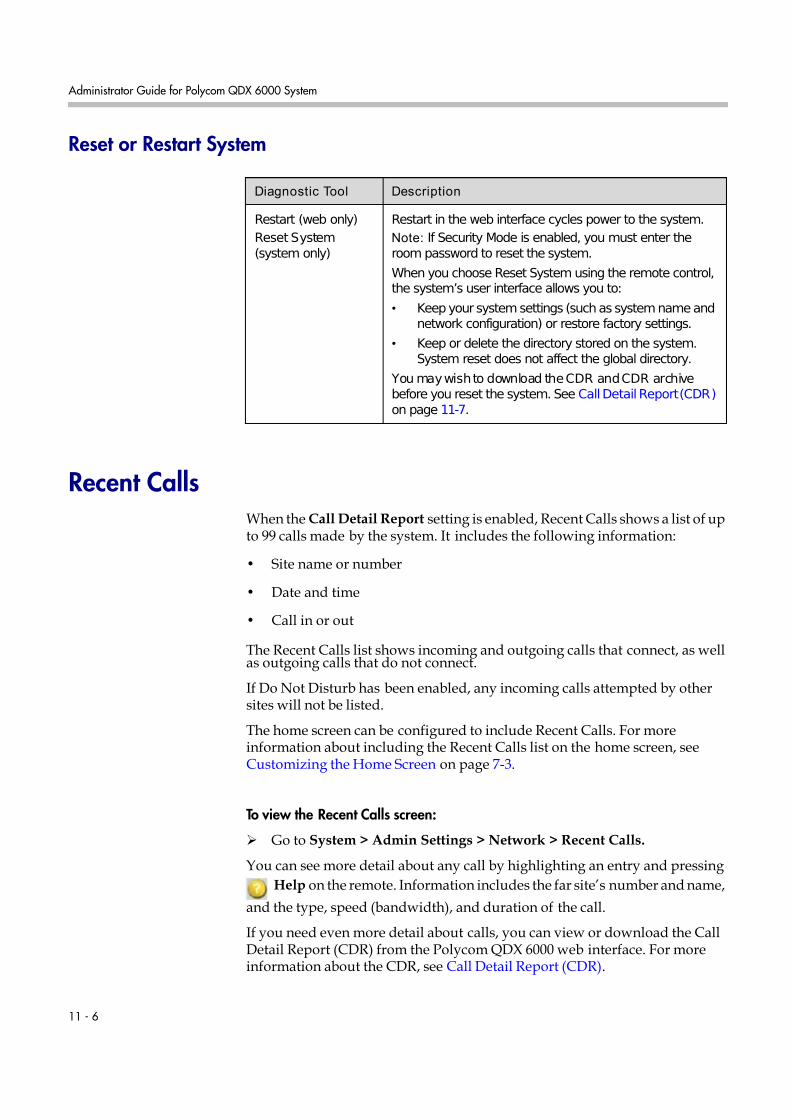
7/16/2019 QDX 6000 System Administrator Guide
http://slidepdf.com/reader/full/qdx-6000-system-administrator-guide 100/126
Administrator Guide for Polycom QDX 6000 System
11 - 6
Reset or Restart System
Recent CallsWhen the Call Detail Report setting is enabled, Recent Calls shows a list of upto 99 calls made by the system. It includes the following information:
• Site name or number
• Date and time
• Call in or out
The Recent Calls list shows incoming and outgoing calls that connect, as wellas outgoing calls that do not connect.
If Do Not Disturb has been enabled, any incoming calls attempted by othersites will not be listed.
The home screen can be configured to include Recent Calls. For moreinformation about including the Recent Calls list on the home screen, seeCustomizing the Home Screen on page 7-3.
To view the Recent Calls screen:
Go to System > Admin Settings > Network > Recent Calls.
You can see more detail about any call by highlighting an entry and pressing
Help on the remote. Information includes the far site’s number and name,
and the type, speed (bandwidth), and duration of the call.
If you need even more detail about calls, you can view or download the CallDetail Report (CDR) from the Polycom QDX 6000 web interface. For moreinformation about the CDR, see Call Detail Report (CDR).
Diagnostic Tool Description
Restart (web only)
Reset System(system only)
Restart in the web interface cycles power to the system.
Note: If Security Mode is enabled, you must enter theroom password to reset the system.
When you choose Reset System using the remote control,the system’s user interface allows you to:
• Keep your system settings (such as system name andnetwork configuration) or restore factory settings.
• Keep or delete the directory stored on the system.System reset does not affect the global directory.
You may wish to download the CDR and CDR archivebefore you reset the system. See Call Detail Report (CDR) on page 11-7.

7/16/2019 QDX 6000 System Administrator Guide
http://slidepdf.com/reader/full/qdx-6000-system-administrator-guide 101/126
Statistics and Diagnostics
11 - 7
Call Detail Report (CDR)When enabled, the Call Detail Report (CDR) provides the system’s call history.You can view the CDR from the Polycom QDX 6000 web interface. Within 5
minutes of the end of the call, the CDR is written to memory and then you candownload the data in CSV format for sorting and formatting.
Every call that connects is added to the CDR, whether it is a call that you makeor that you receive. If a call does not connect, the report shows the reason.
The CDR does not include incoming calls that the Polycom QDX 6000 systemdoes not answer, so if calls were missed while Do Not Disturb was enabled,details will not be included in the CDR.
To view and download the CDR via the Polycom QDX 6000 web interface:
1. On a computer, open a web browser.
2. In the browser address line, enter the system’s IP address, for example,ht t p: / / 10. 11. 12. 13, to go to the Polycom QDX 6000 web interface.
3. If prompted, enter the administrator account ( “admin” is default), andenter the admin password.
4. Click Utilities > Call Detail Report to view the details of the file.
5. Click Save and then specify a location on your computer to save the file.
Information in the CDR
The following table describes the data fields in the CDR.
Data Description
Row ID Each call is logged on the first available row. A call is aconnection to a single site, so there may be more than onecall in a conference.
Start Date The call start date, in the format dd-mm-yyyy.
Start Time The call start time, in the 24-hour format hh:mm:ss.
End Date The call end date.
End Time The call end time.
Call Duration The length of the call.
Account Number If Require Account Number to Dial is enabled on thesystem, the value entered by the user is displayed in thisfield.
Remote SystemName
The far site’s system name.

7/16/2019 QDX 6000 System Administrator Guide
http://slidepdf.com/reader/full/qdx-6000-system-administrator-guide 102/126
Administrator Guide for Polycom QDX 6000 System
11 - 8
Call Field Number 1 The number dialed from the first call field, not necessarilythe transport address.
For incoming calls — The caller ID information from the firstnumber received from a far site.
Call Field Number 2
(If applicable forcall)
For outgoing calls — The number dialed from the secondcall field, not necessarily the transport address.
For incoming calls — The caller ID information from thesecond number received from a far site.
Transport Type The type of call — Either H.323 (IP) or SIP.
Call Rate The bandwidth negotiated with the far site.
SystemManufacturer
The name of the system manufacturer, model, and softwareversion, if they can be determined.
Call Direction In — For calls received.Out — For calls placed from the system.
Conference ID A number given to each conference. A conference caninclude more than one far site, so there may be more thanone row with the same conference ID.
Call ID Identifies individual calls within the same conference.
Endpoint Alias The alias of the far site.
Endpoint AdditionalAlias
An additional alias of the far site.
Endpoint Type Terminal, gateway, or MCU.
Endpoint TransportAddress
The actual address of the far site (not necessarily theaddress dialed).
Audio Protocol (Tx) The audio protocol transmitted to the far site, such as G.728or G.722.1.
Audio Protocol (Rx) The audio protocol received from the far site, such as G.728or G.722.
Video Protocol (Tx) The video protocol transmitted to the far site, such as H.263or H.264.
Video Protocol (Rx) The video protocol received from the far site, such as H.261or H.263.
Video Format (Tx) The video format transmitted to the far site, such as CIF orSIF.
Video Format (Rx) The video format received from the far site, such as CIF orSIF.
Disconnect Reason The description of the Q.850 (ISDN) cause code showinghow the call ended.
Data Description

7/16/2019 QDX 6000 System Administrator Guide
http://slidepdf.com/reader/full/qdx-6000-system-administrator-guide 103/126
Statistics and Diagnostics
11 - 9
Call Detail Report Archives
Calls are added to the CDR until the file size reaches 50 KB, which is equivalentto about 150 calls. The system then automatically archives the CDR and createsa new CDR file. If an archive is already present, the new archive overwrites it.
Average Percent of Packet Loss (Tx)
The combined average of the percentage of both audio andvideo packets transmitted that were lost during the 5
seconds preceding the moment at which a sample wastaken. This value does not report a cumulative average forthe entire H.323 call. However, it does report an average of the sampled values.
Average Percent of Packet Loss (Rx)
The combined average of the percentage of both audio andvideo packets received that were lost during the 5 secondspreceding the moment at which a sample was taken. Thisvalue does not report a cumulative average for the entireH.323 call. However, it does report an average of thesampled values.
Average PacketsLost (Tx)
The number of packets transmitted that were lost during anH.323 call.
Average PacketsLost (Rx)
The number of packets from the far site that were lostduring an H.323 call.
Average Latency(Tx)
The average latency of packets transmitted during an H.323call based on round-trip delay, calculated from sample testsdone once per minute.
Average Latency(Rx)
The average latency of packets received during an H.323call based on round-trip delay, calculated from sample testsdone once per minute.
Maximum Latency(Tx)
The maximum latency for packets transmitted during anH.323 call based on round-trip delay, calculated fromsample tests done once per minute.
Maximum Latency(Rx)
The maximum latency for packets received during an H.323call based on round-trip delay, calculated from sample testsdone once per minute.
Average J itter (Tx) The average jitter of packets transmitted during an H.323call, calculated from sample tests done once per minute.
Average J itter (Rx) The average jitter of packets received during an H.323 call,calculated from sample tests done once per minute.
Maximum J itter (Tx) The maximum jitter of packets transmitted during an H.323call, calculated from sample tests done once per minute.
Maximum J itter (Rx) The maximum jitter of packets received during an H.323call, calculated from sample tests done once per minute.
Data Description

7/16/2019 QDX 6000 System Administrator Guide
http://slidepdf.com/reader/full/qdx-6000-system-administrator-guide 104/126
Administrator Guide for Polycom QDX 6000 System
11 - 10
The CDR starts with Row 1, but the conference numbers continue from the filemost recently archived. Conference numbering restarts at 1 after the systemassigns conference number 100,000.
To view and download a CDR archive via the Polycom QDX 6000 web interface:
1. On a computer, open a web browser.
2. In the browser address line, enter the system’s IP address, for example,ht t p: / / 10. 11. 12. 13, to go to the Polycom QDX 6000 web interface.
3. If prompted, enter the administrator account ( “admin” is default), andenter the admin password.
4. Click Utilities > Call Detail Report to view the details of the file.
5. Click Save Archive and then specify a location on your computer to savethe file.
System LogsYou can use the Polycom QDX 6000 system local interface or web interface todownload system logs.
Downloading System Logs from the Polycom QDX 6000 Web Interface
The support information package contains logs, configuration settings, andother diagnostic information.
To download a system log via the Polycom QDX 6000 web interface:
1. On a computer, open a web browser.
2. In the browser address line, enter the system’s IP address, for example,ht t p: / / 10. 11. 12. 13, to go to the Polycom QDX 6000 web interface.
3. If prompted, enter the administrator account ( “admin” is default), andenter the admin password.
4. Click Diagnostics > System Log > Download Logs.
5. Click Download support information package and then specify a
location on your computer to save the file.

7/16/2019 QDX 6000 System Administrator Guide
http://slidepdf.com/reader/full/qdx-6000-system-administrator-guide 105/126
Statistics and Diagnostics
11 - 11
System Log Settings in the Polycom QDX 6000 Web Interface
To configure system log settings via the Polycom QDX 6000 web interface:
1. On a computer, open a web browser.
2. In the browser address line, enter the system’s IP address, for example,ht t p: / / 10. 11. 12. 13, to go to the Polycom QDX 6000 web interface.
3. If prompted, enter the administrator account ( “admin” is default), andenter the admin password.
4. Click Diagnostics > System Log > System Log Settings.
5. Configure these settings:
Setting Description
Log Level Sets the minimum log level of messages stored in thePolycom QDX 6000 system flash memory. DEBUG logsall messages. WARNING logs the fewest number of messages.
Polycom recommends leaving this setting at the defaultvalue of DEBUG.
Remote Logging
Enabled
Specifies whether remote logging is enabled. Enablingthis setting causes the Polycom QDX 6000 system tosend each log message to the specified server in additionto logging it locally.
The system immediately begins forwarding its logmessages when you click Update.
Encryption is not supported for remote logging, soPolycom recommends remote logging only for secure,local networks.
Remote Log Server Specifies the domain name or IP address of the syslogserver. The server must support the standard syslogprotocol (RFC 3164).
Enable H.323 Trace Logs additional H.323 connectivity information.

7/16/2019 QDX 6000 System Administrator Guide
http://slidepdf.com/reader/full/qdx-6000-system-administrator-guide 106/126
Administrator Guide for Polycom QDX 6000 System
11 - 12

7/16/2019 QDX 6000 System Administrator Guide
http://slidepdf.com/reader/full/qdx-6000-system-administrator-guide 107/126
12 - 1
12
Troubleshooting
Placing a Test CallWhen you finish configuring the system, you can use one of the samplenumbers in the directory to test your setup.
To place a test call:
1. On the home screen, select Directory from the remote control.
2. Select Group.
3. Select Sample Sites and highlight a location.
4. Press Call on the remote control or keypad.
You can also find a list of worldwide numbers that you can use to test yourPolycom QDX 6000 system at www.polycom.com/videotest.
If you have trouble making video calls:
• Make sure the number you dialed is correct, then try the call again. Forexample, you may need to dial 9 for an outside line or include a longdistance access code or country code.
• To find out if the problem exists in your system, ask the person you weretrying to reach to call you instead.
• Find out if the system you are calling has its power turned on and isfunctioning properly.
• If you can make calls but not receive them, make sure that your system isconfigured with the correct number.
7/16/2019 QDX 6000 System Administrator Guide
http://slidepdf.com/reader/full/qdx-6000-system-administrator-guide 108/126
Administrator Guide for Polycom QDX 6000 System
12 - 2
Enabling Basic ModeBasic Mode is a limited operating mode that uses H.261 for video and G.711for audio. It provides administrators with a workaround for interoperability
issues that cannot be solved using other methods. The Basic Mode setting staysin effect until you change it.
To enable Basic Mode in the Polycom QDX 6000 system interface:
1. Go to System > Admin Settings > Network > Call Preference.
2. Select Basic Mode.
To enable Basic Mode using the Polycom QDX 6000 web interface:
1. On a computer, open a web browser.
2. In the browser address line, enter the system’s IP address, for example,ht t p: / / 10. 11. 12. 13, to go to the Polycom QDX 6000 web interface.
3. Go to Admin Settings > Network > Call Preference.
4. Select Enable Basic Mode.
Using the Restore ButtonYou can use the hardware restore button on the Polycom QDX 6000 system toreset the system in this way:
Factory restore—Completely erases the system and restores it to:
• Its original factory 4.0 software version and default configuration, or
• The last 4.0 software version that was loaded to the system using 3.0 to 4.0upgrade procedure.
Basic Mode disables many system features such as content sharing, far endcamera control, AES encryption, and advanced audio and video algorithms. UseBasic Mode only when calling systems that fail to operate properly with theseadvanced features.
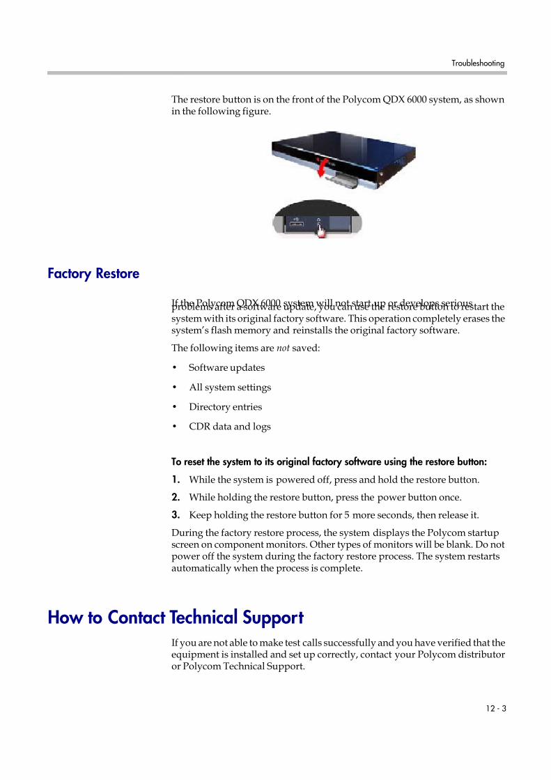
7/16/2019 QDX 6000 System Administrator Guide
http://slidepdf.com/reader/full/qdx-6000-system-administrator-guide 109/126
Troubleshooting
12 - 3
The restore button is on the front of the Polycom QDX 6000 system, as shownin the following figure.
Factory Restore
If the Polycom QDX 6000 system will not start up or develops seriousproblems after a software update, you can use the restore button to restart thesystem with its original factory software. This operation completely erases thesystem’s flash memory and reinstalls the original factory software.
The following items are not saved:
• Software updates
• All system settings
• Directory entries
• CDR data and logs
To reset the system to its original factory software using the restore button:
1. While the system is powered off, press and hold the restore button.
2. While holding the restore button, press the power button once.
3. Keep holding the restore button for 5 more seconds, then release it.
During the factory restore process, the system displays the Polycom startupscreen on component monitors. Other types of monitors will be blank. Do notpower off the system during the factory restore process. The system restartsautomatically when the process is complete.
How to Contact Technical Support If you are not able to make test calls successfully and you have verified that theequipment is installed and set up correctly, contact your Polycom distributoror Polycom Technical Support.

7/16/2019 QDX 6000 System Administrator Guide
http://slidepdf.com/reader/full/qdx-6000-system-administrator-guide 110/126
Administrator Guide for Polycom QDX 6000 System
12 - 4
To contact Polycom Technical Support, go to www.polycom.com/support.
Enter the following information, then ask a question or describe the problem.This information helps us to respond faster to your issue:
• The 16-digit serial number from the System Information screen or the backof the system
• The software version (from the home screen, select System > SystemInformation)
• Information about your network
• Troubleshooting steps you have already tried
7/16/2019 QDX 6000 System Administrator Guide
http://slidepdf.com/reader/full/qdx-6000-system-administrator-guide 111/126
Regulatory Notices - 1
Regulatory Notices
Important Safeguards
Read and understand the following instructions before using the system:
• Close supervision is necessary when the system is used by or near children. Do not leave unattended while inuse.
• Only use electrical extension cords with a current rating at least equal to that of the system.
• Always disconnect the system from power before cleaning and servicing and when not in use.
• Do not spray liquids directly onto the system when cleaning. Always apply the liquid first to a static free cloth.
• Do not immerse the system in any liquid or place any liquids on it.
• Do not disassemble this system. To reduce the risk of shock and to maintain the warranty on the system, aqualified technician must perform service or repair work.
• Connect this appliance to a grounded outlet.
• Only connect the system to surge protected power outlets.
• Keep ventilation openings free of any obstructions.
• If the system or any accessories are installed in an enclosed space such as a cabinet, ensure that the air
temperature in the enclosure does not exceed 40°C (104° F). You may need to provide forced cooling to keepthe equipment within its operating temperature range.
• Do not use this product near water.
• Avoid using this product during an electrical storm. There may be a remote risk of electric shock from lighting.
SAVE THESE INSTRUCTIONS.
Electrical Specifications
Polycom QDX 6000 system: 100-240 VAC, 50-60 Hz, 1.5A

7/16/2019 QDX 6000 System Administrator Guide
http://slidepdf.com/reader/full/qdx-6000-system-administrator-guide 112/126
Administrator Guide for Polycom QDX 6000 System
Regulatory Notices - 2
License Restrictions
THE SOFTWARE PROGRAMS CONTAINED OR DESCRIBED HEREIN ARE CONFIDENTIAL INFORMATIONAND PROPRIETARY PRODUCTS OF POLYCOM, INC. OR ITS LICENSORS.
Buyer shall not sublicense or otherwise distribute any of the Subject Programs except to End Users and/or resellerswho have entered into a Sublicense Agreement. For purposes of this Agreement a “Sublicense Agreement” shallmean a written license agreement between the Buyer and its purchaser, or, in the case of any sale by Buyer to areseller, between such reseller and the End User, that is either 1) signed by the End User or 2) included with theDocumentation, in such a manner that the End User reasonably indicates its acceptance of the SublicenseAgreement by turning on and using the Computer Equipment. Polycom, Inc. shall include so-called “break the sealsoftware licenses” with the Documentation, and Buyer shall not remove or alter any such Sublicense Agreementsor any notifications or warning stickers relating thereto. Buyer shall not waive, amend, or otherwise modify anySublicense Agreement without Polycom’s prior consent.
Title to all Subject Programs shall at all times remain and vest solely with Polycom, Inc. and its licensors. Buyeracknowledges Polycom’s claim that the Subject Programs are its trade secret and confidential property, and shalltreat them as such. Buyer will not attempt to disassemble, decompile, reverse-engineer or otherwise endeavor to
discover or disclose the methods and concepts embodied in the Subject Programs. Except as expressly allowedunder this Agreement, the Buyer shall not copy, modify, transcribe, store, translate, sell, lease, or otherwise transferor distribute any of the Subject Programs in whole or in part, without prior authorization, in writing, from Polycom,Inc. Buyer shall not remove or destroy any copyright, patent, trademark or other proprietary mark or notice onComputer Equipment, and shall reproduce any such marks on any copies of Subject Programs that it makeshereunder.
You shall not, and shall not allow, any third party to 1) decompile, disassemble, or otherwise reverse-engineer orattempt to reconstruct or discover any source code or underlying ideas or algorithms of the software by any meanswhatsoever or 2) remove any product.
Warranty Information
LIMITED WARRANTY. Polycom warrants to the end user (“Customer”) that the product will be free from defects inworkmanship and materials, under normal use and service, for one year, or such longer period as Polycom mayannounce publicly from time to time for particular products, from the date of purchase from Polycom or itsauthorized reseller. This warranty covers the product acquired by the consumer including all of its accessories,components, and parts thereto.
Polycom’s sole obligation under this express warranty shall be, at Polycom’s option and expense, to repair thedefective product or part, deliver to Customer an equivalent product or part to replace the defective item, or if neither of the two foregoing options is reasonably available, Polycom may, in its sole discretion, refund to Customerthe purchase price paid for the defective product. All products that are replaced will become the property of Polycom. Replacement products or parts may be new or reconditioned. Polycom warrants any replaced or repairedproduct or part for ninety (90) days from shipment, or the remainder of the initial warranty period, whichever islonger.
Products returned to Polycom must be sent prepaid and packaged appropriately for safe shipment, and it isrecommended that they be insured or sent by a method that provides for tracking of the package. Responsibility forloss or damage does not transfer to Polycom until the returned item is received by Polycom. The repaired orreplaced item will be shipped to Customer, at Polycom's expense, not later than thirty (30) days after Polycomreceives the defective product, and Polycom will retain risk of loss or damage until the item is delivered toCustomer.

7/16/2019 QDX 6000 System Administrator Guide
http://slidepdf.com/reader/full/qdx-6000-system-administrator-guide 113/126
Regulatory Notices
Regulatory Notices - 3
EXCLUSIONS. POLYCOM WILL NOT BE LIABLE UNDER THIS LIMITED WARRANTY IF ITS TESTING ANDEXAMINATION DISCLOSE THAT THE ALLEGED DEFECT OR MALFUNCTION IN THE PRODUCT DOES NOT
EXIST OR RESULTS FROM:• FAILURE TO FOLLOW POLYCOM'S INSTALLATION, OPERATION, OR MAINTENANCE INSTRUCTIONS.
• UNAUTHORIZED PRODUCT MODIFICATION OR ALTERATION.
• UNAUTHORIZED USE OF COMMON CARRIER COMMUNICATION SERVICES ACCESSED THROUGH THE PRODUCT.
• ABUSE, MISUSE, NEGLIGENT ACTS OR OMISSIONS OF CUSTOMER AND PERSONS UNDERCUSTOMER'S CONTROL; OR
• ACTS OF THIRD PARTIES, ACTS OF GOD, ACCIDENT, FIRE, LIGHTING, POWER SURGES OR OUTAGES,OR OTHER HAZARDS.
WARRANTY EXCLUSIVE. IF A POLYCOM PRODUCT DOES NOT OPERATE AS WARRANTED ABOVE,CUSTOMER'S SOLE REMEDY FOR BREACH OF THAT WARRANTY SHALL BE REPAIR, REPLACEMENT, ORREFUND OF THE PURCHASE PRICE PAID, AT POLYCOM'S OPTION. TO THE FULL EXTENT ALLOWED BY
LAW, THE FOREGOING WARRANTIES AND REMEDIES ARE EXCLUSIVE AND ARE IN LIEU OF ALL OTHERWARRANTIES, TERMS, OR CONDITIONS, EXPRESS OR IMPLIED, EITHER IN FACT OR BY OPERATION OFLAW, STATUTORY OR OTHERWISE, INCLUDING WARRANTIES, TERMS, OR CONDITIONS OFMERCHANTABILITY, FITNESS FOR A PARTICULAR PURPOSE, SATISFACTORY QUALITY,CORRESPONDENCE WITH DESCRIPTION, AND NON-INFRINGEMENT, ALL OF WHICH ARE EXPRESSLYDISCLAIMED. POLYCOM NEITHER ASSUMES NOR AUTHORIZES ANY OTHER PERSON TO ASSUME FORIT ANY OTHER LIABILITY IN CONNECTION WITH THE SALE, INSTALLATION, MAINTENANCE OR USE OFITS PRODUCTS.
SUPPORT & SERVICE AGREEMENTS. If you purchased your product from a Polycom Authorized Reseller,contact the Authorized Reseller for information about support and service agreements applicable to your product.For information on Polycom service, go to the Polycom web site www.polycom.com, products and services menu,or call 1-800-765-9266, outside the US call 1-408-526-9000, or your local Polycom Office, as listed on the PolycomWeb site.
LIMITATION OF LIABILITY. TO THE FULL EXTENT ALLOWED BY LAW, POLYCOM EXCLUDES FOR ITSELFAND ITS SUPPLIERS ANY LIABILITY, WHETHER BASED IN CONTRACT OR TORT (INCLUDINGNEGLIGENCE), FOR INCIDENTAL, CONSEQUENTIAL, INDIRECT, SPECIAL, OR PUNITIVE DAMAGES OFANY KIND, OR FOR LOSS OF REVENUE OR PROFITS, LOSS OF BUSINESS, LOSS OF INFORMATION ORDATA, OR OTHER FINANCIAL LOSS ARISING OUT OF OR IN CONNECTION WITH THE SALE,INSTALLATION, MAINTENANCE, USE, PERFORMANCE, FAILURE, OR INTERRUPTION OF ITS PRODUCTS,EVEN IF POLYCOM OR ITS AUTHORIZED RESELLER HAS BEEN ADVISED OF THE POSSIBILITY OF SUCHDAMAGES, AND LIMITS ITS LIABILITY TO REPAIR, REPLACEMENT, OR REFUND OF THE PURCHASEPRICE PAID, AT POLYCOM'S OPTION. THIS DISCLAIMER OF LIABILITY FOR DAMAGES WILL NOT BEAFFECTED IF ANY REMEDY PROVIDED HEREIN SHALL FAIL OF ITS ESSENTIAL PURPOSE.
DISCLAIMER. Some countries, states, or provinces do not allow the exclusion or limitation of implied warranties orthe limitation of incidental or consequential damages for certain products supplied to consumers, or the limitation of liability for personal injury, so the above limitations and exclusions may be limited in their application to you. When
the implied warranties are not allowed to be excluded in their entirety, they will be limited to the duration of theapplicable written warranty. This warranty gives you specific legal rights which may vary depending on local law.
GOVERNING LAW. This Limited Warranty and Limitation of Liability shall be governed by the laws of the State of California, U.S.A., and by the laws of the United States, excluding their conflicts of laws principles. The UnitedNations Convention on Contracts for the International Sale of Goods is hereby excluded in its entirety fromapplication to this Limited Warranty and Limitation of Liability.
Warranty Information

7/16/2019 QDX 6000 System Administrator Guide
http://slidepdf.com/reader/full/qdx-6000-system-administrator-guide 114/126
Administrator Guide for Polycom QDX 6000 System
Regulatory Notices - 4
Regulatory Notices
USA and Canadian Regulatory Notices
This Class [A] digital apparatus complies with Canadian ICES-003.
Cet appareil numérique de la classe [A] est conforme à la norme NMB-003 du Canada
This device complies with part 15 of the FCC Rules. Operation is subject to the following two conditions: Thisdevice may not cause harmful interference, and this device must accept any interference received, includinginterference that may cause undesired operation
NOTE: This equipment has been tested and found to comply with the limits for a Class A digital device, pursuant topart 15 of the FCC Rules. These limits are designed to provide reasonable protection against harmful interferencewhen the equipment is operated in a commercial environment. This equipment generates, uses, and can radiateradio frequency energy and, if not installed and used in accordance with the instruction manual, may cause harmfulinterference to radio communications. Operation of this equipment in a residential area is likely to cause harmfulinterference in which case the user will be required to correct the interference at his own expense
In accordance with part 15 of the FCC rules, the user is cautioned that any changes or modifications not expressly
approved by Polycom Inc. could void the user's authority to operate the equipment.
EU Regulatory Notices
This QDX6000 has been marked with the CE mark. This mark indicates compliance with EEC Directives2006/95/EC and 2004/108/EC. A full copy of the Declaration of Conformity can be obtained from Polycom Ltd, 270Bath Road, Slough, Berkshire, SL1 4DX, UK.

7/16/2019 QDX 6000 System Administrator Guide
http://slidepdf.com/reader/full/qdx-6000-system-administrator-guide 115/126
Regulatory Notices
Regulatory Notices - 5
WARNING
This is a Class A product. In a domestic environment this product may cause radio interference in which case the
user may be required to take adequate measures.Electrical safety advisory
We recommend that you install an AC surge arrestor in the AC outlet to which this device is connected. This actionwill help to avoid damage to the equipment caused by local lightning strikes and other electrical surges.
Underwriters Laboratories Statement
The system is intended to be powered only by the supplied power supply unit.
Special Safety Instructions
Follow existing safety instructions and observe all safeguards as directed.
Installation Instructions
Installation must be performed in accordance with all relevant national wiring rules.
Mechanical Loading - Mounting of the equipment in the rack should be such that a hazardous condition is notachieved due to uneven mechanical loading.
Circuit Overloading - Consideration should be given to the connection of the equipment to the supply circuit and theeffect that overloading of the circuits might have on over current protection and supply wiring. Appropriateconsideration of equipment nameplate ratings should be used when addressing this concern.
Reliable Earthing - Reliable earthing of rack-mounted equipment should be maintained. Particular attention shouldbe given to supply connections other than direct connections to the branch circuit (e.g. use of power strips)."
Plug Acts as Disconnect Device
The socket outlet to which this apparatus is connected must be installed near the equipment and must always bereadily accessible.
Lithium coin cell warning
This equipment contains a Lithium coin cell which is not user serviceable. Refer servicing to qualified servicepersonnel only. Do not attempt to open the case of this product.
Caution
Danger of Explosion if Battery is incorrectly replaced.
Replace only with the same or equivalent type
Recommended by the manufacturer.
Dispose of used batteries according to the manufacturer's instructions
Regulatory Notices

7/16/2019 QDX 6000 System Administrator Guide
http://slidepdf.com/reader/full/qdx-6000-system-administrator-guide 116/126
Administrator Guide for Polycom QDX 6000 System
Regulatory Notices - 6

7/16/2019 QDX 6000 System Administrator Guide
http://slidepdf.com/reader/full/qdx-6000-system-administrator-guide 117/126
A - 1
A
System Back Panel Views and Cables
Video Inputs and Outputs
Video Output 1: YPrPb, RCA, and S-Videofor the main monitor
Video Output 2:RCA, S-Video and VGAfor the second monitor
Video Input 5:
VGA for playing contentfrom a computer into calls
Video Input 1 and Video Input 2 :S-Video for main cameraRCA for auxiliary camera
Video Input 3 and Video Input 4:S-Video for document cameraRCA for VCR/DVD to play content into calls

7/16/2019 QDX 6000 System Administrator Guide
http://slidepdf.com/reader/full/qdx-6000-system-administrator-guide 118/126
Administrator Guide for Polycom QDX 6000 System
A - 2
Audio Inputs and Outputs
Network/Power Inputs and Outputs
Audio Outputs:For line audio and
VCR/DVD player audio
Audio Input:For microphone
Audio Inputs:For line audio andVCR/DVD player audio
Camera control interface
LAN port: For IP or SIP calls,People+Content IP, and PolycomQDX 6000 Web Interface
RS-232 serial port s:For RS-232 devices
Power connector andPower switch

7/16/2019 QDX 6000 System Administrator Guide
http://slidepdf.com/reader/full/qdx-6000-system-administrator-guide 119/126
System Back Panel Views and Cables
A - 3
System Cables
Cable Part Number and Description
2457-08343-001 LAN Cable
2457-30836-001 YPbPr Cable
2457-32613-001 VGA Cable
2457-08674-002 Quade Cable
1456-00286-001 Power cable
2457-30821-001 Camera Cable
The appearance of your system cables may differ slightly from the cables in this
table. The figures here are for illustration purposes only.

7/16/2019 QDX 6000 System Administrator Guide
http://slidepdf.com/reader/full/qdx-6000-system-administrator-guide 120/126
Administrator Guide for Polycom QDX 6000 System
A - 4
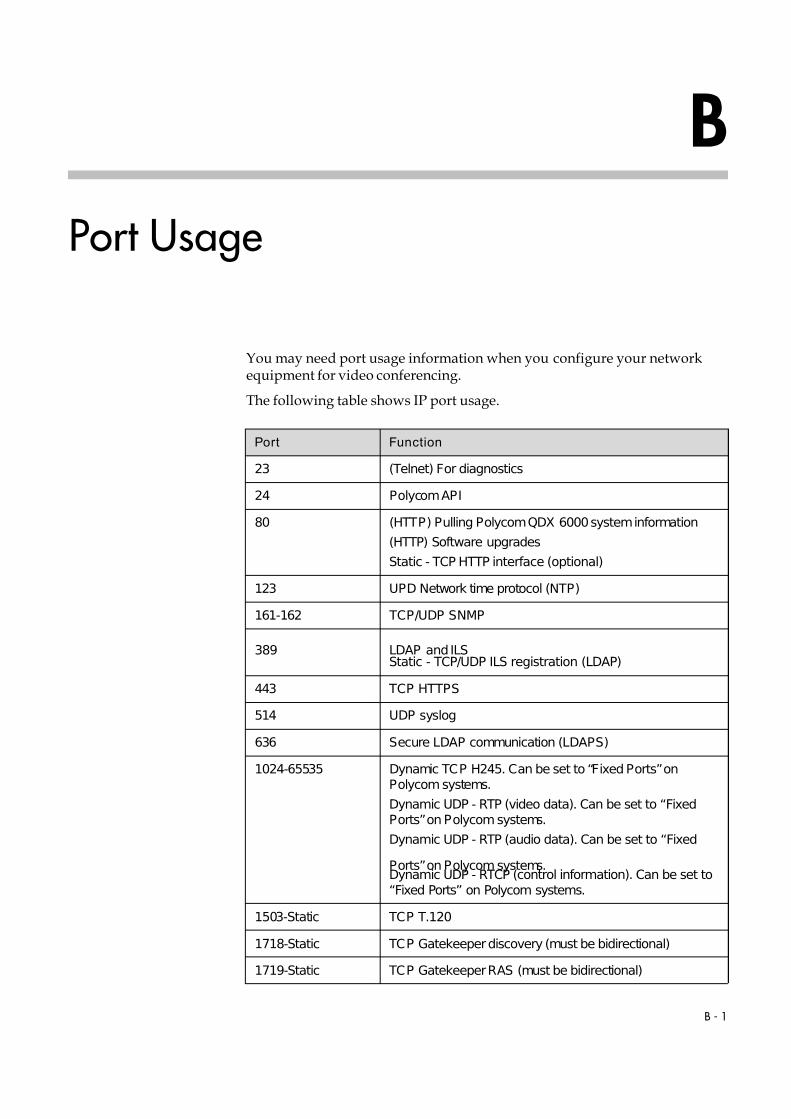
7/16/2019 QDX 6000 System Administrator Guide
http://slidepdf.com/reader/full/qdx-6000-system-administrator-guide 121/126
B - 1
B
Port Usage
You may need port usage information when you configure your networkequipment for video conferencing.
The following table shows IP port usage.
Port Function
23 (Telnet) For diagnostics
24 Polycom API
80 (HTTP) Pulling Polycom QDX 6000 system information
(HTTP) Software upgrades
Static - TCP HTTP interface (optional)
123 UPD Network time protocol (NTP)
161-162 TCP/UDP SNMP
389 LDAP and ILSStatic - TCP/UDP ILS registration (LDAP)
443 TCP HTTPS
514 UDP syslog
636 Secure LDAP communication (LDAPS)
1024-65535 Dynamic TCP H245. Can be set to “Fixed Ports” onPolycom systems.
Dynamic UDP - RTP (video data). Can be set to “FixedPorts” on Polycom systems.
Dynamic UDP - RTP (audio data). Can be set to “Fixed
Ports” on Polycom systems.Dynamic UDP - RTCP (control information). Can be set to“Fixed Ports” on Polycom systems.
1503-Static TCP T.120
1718-Static TCP Gatekeeper discovery (must be bidirectional)
1719-Static TCP Gatekeeper RAS (must be bidirectional)

7/16/2019 QDX 6000 System Administrator Guide
http://slidepdf.com/reader/full/qdx-6000-system-administrator-guide 122/126
Administrator Guide for Polycom QDX 6000 System
B - 2
1720-Static TCP H.323 call setup (must be bidirectional)
1731-Static TCP Audio call control (must be bidirectional)
3601 TCP (Proprietary - data traffic) - Global directory data
5001 TCP/UDP People+Content IP
5060-Static TCP/UDP SIP call setup (must be bidirectional)
8080-Static TCP HTTP server push (optional)
Port Function

7/16/2019 QDX 6000 System Administrator Guide
http://slidepdf.com/reader/full/qdx-6000-system-administrator-guide 123/126
C - 1
C
Installing Polycom QDX 6000Software
By upgrading your Polycom QDX 6000 software , your organization continues
to benefit from the latest video conferencing technology. This documentdescribes how to upgrade your software.
To activate and install Polycom video software upgrades:
1. Collect your license numbers and system serial numbers.
2. Obtain key codes from the Polycom web site.
3. Download the software update file from the Polycom web site.
4. Install the software.
Each of these steps is described in the following sections.
Collecting License Numbers and System Serial NumbersMake a note of your system serial number and license number. You will needto provide them in order to get the key codes that activate software upgrades.
• The 16-digit serial number is the unique number that identifies yoursystem. You can find it on a label on the back of the system and on theSystem Information screen (Go to System > System Information).
• The license number is the number that you receive when you purchase asoftware upgrade. License numbers have the following format:
U000-0000-0000-0000-0000
If your software upgrades are covered by a software warranty or serviceagreement, you only need to provide a serial number.If you are running a major or minor software version (x.y), you can upgrade to apatch version (x.y.z) without a license.

7/16/2019 QDX 6000 System Administrator Guide
http://slidepdf.com/reader/full/qdx-6000-system-administrator-guide 124/126
Administrator Guide for Polycom QDX 6000 System
C - 2
Obtaining Key Codes for Software UpgradesBefore you run the software update, you need a key code. A key code is thenumber that activates software on a specific system. Polycom generates a key
code when you submit the license number and system serial numberinformation.
• A key code is valid only on the system for which it is generated.
• Software key codes are valid for the software release you are installing aswell as for any patch releases that may later become available.
To obtain software key codes for a system:
1. On a computer, open Internet Explorer version 6.x, 7.x, or 8.x.
2. Log in at www.polycom.com/support/login.
Note that you will need to set up an account if you don’t already have one.
3. Click Activate Your Product.
4. Do one of the following:
— If your system is covered by a software warranty or serviceagreement, click Retrieve Software Key Code. Enter your systemserial number and the version number of the software you want toinstall and click Retrieve.
— If you purchased an upgrade license, enter your system serial numberand license number and click Generate.
The key code displays on the screen. Make a note of this number for use
during installation.
Downloading the Software
To download the software
1. On a computer, open Internet Explorer version 6.x, 7.x, or 8.x.
2. Go to www.polycom.com/support.
3. Navigate to your product software.4. Do one of the following:
— If current software version is 3.x, and please download the .exe file.
— If your current software version is 4.0, please download the .pup file.

7/16/2019 QDX 6000 System Administrator Guide
http://slidepdf.com/reader/full/qdx-6000-system-administrator-guide 125/126
Installing Polycom QDX 6000 Software
C - 3
Installing Software
Installing a Software Upgrade on a System
To update system software from 3.x to 4.0:
Double click the .exe, and follow the instructions on the screen.
To update system software between 4.0 software versions:
1. On a computer, open Internet Explorer version 6.x, 7.x, or 8.x.
2. In the browser address line, enter the system’s IP address, for example,ht t p: / / 10. 11. 12. 13, to go to Polycom QDX 6000 web interface.
3. Go to Admin Settings > General Settings > Software Update, andfollow the instructions on the screen.
Installing a Software Downgrade on a System from 4.0 to 3.x
To downgrade from 4.0 software to 3.x software, you must put the PolycomQDX 6000 system in 3.0 rescue mode.
To downgrade from 4.0 software to 3.x software:
1. Telnet to port 24 on Polycom QDX 6000 system, type ubootconfig v3.
2. Power off the Polycom QDX 6000 system.
3. Hold the rescue mode button for 5 seconds after switching on. PolycomQDX 6000 system will go into the 3.0 rescue mode.
System will reboot to 4.0. The reboot can take about 20 minutes. During this time,the indicator light will blink red. Do not power down the system during the reboot.

7/16/2019 QDX 6000 System Administrator Guide
http://slidepdf.com/reader/full/qdx-6000-system-administrator-guide 126/126
Administrator Guide for Polycom QDX 6000 System
4. At this point, you can follow the normal 3.0 software upgrade procedureto load a 3.0 software to the Polycom QDX 6000 system.
You need to use a 3.0 software upgrade key.


![[XLS] · Web view1 9741676061 6000 33655 2 9945073545 6000 123161 3 9013044974 12000 4 9945788658 20710027003 6000 11500 5 7259805540 527040100005544 12000 6 6000 7 9886502163 6000](https://img.dokumen.tips/doc/110x75/5b015d377f8b9a65618d8ad1/xls-view1-9741676061-6000-33655-2-9945073545-6000-123161-3-9013044974-12000-4.jpg)