Embed Size (px)
Citation preview
QD100 GAS-STEAM COMBINED—CYCLE 15MW POWER SET PROPOSAL
Mongolia country item
CHINA AVIATION GAS TURBINE COMPANY., LTD. 03-11-2006

QD100 燃气-蒸汽联合循环 15MW 发电机组技术建议书 QD100 gas-steam combined cycle15MW power set proposal
中航世新燃气轮机股份有限公司沈阳分公司设计研究所 T024-88451045-8003 版本(A)2006.11 CAGT SHENYANG BRANCH DESIGN AND RESEARCH INSTITUTE release(A)2006.11
1
QD100 GAS-STEAM COMBINED—CYCLE
15MW POWER SET PROPOSAL
content
1 China Aviation shixin gas turbine com.,ltd. Introduction--------------1
2 The data which provided in the forepart-----------------------------------6
3 QD100Gas-steam combined cycle genset assembly solution------8
4 Fuel supply-----------------------------------------------------------------------39
5 Cooling water system and compress air system requirement of the
Combined-Cycle unit ----------------------------------------------------------42
6 Environmental protection-----------------------------------------------------44
7 Scope of supply-----------------------------------------------------------------46
8 design、manufacture and accept standard------------------------------58
9 Power Set Manufacturing cycle---------------------------------------------60
10 After service-----------------------------------------------------------------------60
11 Attached drawing-----------------------------------------------------------------65

1.China Aviation shixin gas turbine com., ltd. Introduction 1.1 Company profile
General
China Aviation shixin gas turbine com.,ltd.(hereinafter use the CAGT for short)as a gas turbine package company ,established by 13 independent share holders in
accordance with the requirement of public companies as the results of the effective resource consolidation of the gas turbine core business within China Aviation Industry
Corporation, Authorized by State Economic &Trade Commission, Authorize document No:2002-814,Booking in the State Administration for Industry &Commerce on Dec
25,2002. On Jan 10 2003,CAGT achieved the Certificate for High &New Technology Enterprise awarded by Beijing Science &Technology Committee. CAGT accede the
gas turbine business of the companies belong to China aviation industry corporation I.. Its main business include: Design, development, manufacture and package of gas turbine
unit ; Introduction and package of foreign gas turbine unit ; Prime contract of gas turbine unit , installation and commissioning, maintenance and repair ,running
management ,spare parts supply of gas turbine ; Consultation ,planning ,service of gas turbine and related power engineering projects.
CAGT comprise of Shenyang branch, technical center, market department, quality control department, operating and planning department, general managing department
and finance accounting department.
CAGT Shenyang branch is one entity belong to CAGT. It is a High &New Technology Enterprise. Its main business include::Design, development, manufacture and
package of gas turbine unit ; Introduction and package of foreign gas turbine unit ; Prime contract of gas turbine unit , installation and commissioning, maintenance and
repair ,running management ,spare parts supply of gas turbine ; Consultation ,planning ,service of gas turbine and related power engineering projects. Design and manufacture
of product line of Electro-mechanical equipment , non-standard ,special & test equipment , pressure vessel , thermalization product, and torch burmer etc. Shenyang branch is
the research and manufacture basement of CAGT.
Human resource: Now, CAGT has 1,200 employees. Among them 105 employees are senior technicians (8.5%), 304 employees are intermediate technicians (26.4%).
Machining capability: Machining workshop: 21,640 m2 ; Machining equipment : more than 230 sets; Machining capability:866,250 hours per year; Welding equipment:200
sets; Welding capability:750,000hours per year
When the new modern workshop (18,000m2) special for gas turbine packaging come into use, i t will has the production capability that package 20 sets medium and
small gas turbine.
1.2 Product and achievement
China aviation industry corporation I develop the WP6G cogeneration industry gas turbine genset based on the aeroengine technology at the end of 1970s. it
generates electricity power 4.8MW、produce heat 4×10⁷kJ/h. The unit was developed successfully in 1984. It was installed and put into production in Daqing. After that,
another 11 sets WP6G gas turbine units were supllied to Daqing, shengli, zhongyuan and Qinghai oil field in succession. They have been run more than 800,000 hours till the
August ,2003. The units make their contribution to make up electric power shortage for oil field.
At the end of 1980’s, according to the market requirement, the company developed the following business: installation, maintaince, operation and overhauling for imported
gas turbine units. Up to August of 2003, the company finished installing and com missioning 50 sets gensets of 14 types imported gas turbines at home and abroad. The main
types include: LM2500、LM5000、LM6000、MS5001、MS6001、MS9001E、Taurus60、Mars100、Titan130、SK15HE、FT8twin、Typhoon、GT13D and GT13E2;Ten types
(MS5001、MS6001、MS9001E、W101、GT13D、GT13E2、SK15HE、KG5、251B11 及 V94.2) gas turbine gensets and five types(MS1002D、MS5001、Centaur40、
Tornado 及 PGT10)gas turbine compressors(altogether 208 sets) were examined ,repaired and overhauled at field; Many kinds of heat components of gas turbine(combustor
flame chamber, changeover portion, turbine nozzle segment, turbine blade) were repaired. CAGT is a specially enterprise with rich experience. It installed and overhauled the
most of imported gas turbine gensets in domestic.
When came into 2000’s, the company developed QD128 type(12.8MW)and QD70 type (7MW) gas turbine genset with success. The two types adopt domestic advanced
modified aeroengine as the gas turbine. The fist set of QD128 and QD70 both used as demonstrating unit were installed at Wenliu and Pucheng generating station of
Zhongyuan oil field. In July of 2003, the units paralleled with grid and came into commercial operation.

To meet domestic and international market requirement and continually improve competition ability of domestic gas turbine industry, CAGT introduced advanced gas
turbine and its package technology through international cooperation in 2002. CAGT signed the entire cooperation agreement with GE oil and gas company (GE/NP) about
purchasing GE10-1 type gas turbine. QD100 type gas turbine genset (10MW) designed and developed by CAGT just use the GE10-1 gas turbine which has advanced
technology and high efficiency.
With the principle of“unified product planning ,unified product research and development ,unified product packages ,and unified after-sales service”,CAGT makes full use of
its first-class aviation power technologies ,equipment and the integral advantages with distinctive features ,and actively participates in the competitions on both the domestic and
international gas turbine markets ,so as to provide the clients with sets of high-quality gas turbines and their power engineering service.
CAGT enterprise spirit:Creating Harmony ,Pursuing Excellence.
CAGT enterprise philosophy:Creating value for users ,Creating profit for shareholders,Creating future for employees,and Creating prosperity for society.
2. The information which provided in the forepart
CAGT (China Aviation gas turbine co., ltd), as the company which deals with the gas turbine package and service, is interested in the EPC construction project of your
power plant. To work out the most optimal project as soon as possible, please provide the data as follow:
2.1.The size of power plant and investment&production project of unit (cycle mode, simple cycle orcombined cycle, automatic degree)
2.2. GT fuel type, component, pressure, flow, temperature, impurity,( natural gas/fuel oil)
2.3. Power feeding condition, for example voltage on power circuit, connection mode, etc.
2.4. Construction period
2.5. Transportation and installtion condition
2.6. Water source condition
2.7. Field condition,hydrographic condition, weather condition and geologic condition

Annual average temperature ℃
the highest air temperature of the past years ℃
the lowest air temperature of the past years ℃
annual average relative humidity %
maximum g/m3
minimum g/m3
annual rainfall mm
Annual average air pressure mba
past years average wind speed m/s
altitude height of the factory site m
the load supporting for foundation kPa
basic earthquake intensity
With the owners damand,the above information will help us to make a configuration as accurate as possible
3. QD100Gas-steam combined cycle genset assembly solution
3.1 operating principle
Operating principle of the gas-steam combined cycle genset as follow: the suction air (achived by gas turbine ) from the free air will be compreesed by the compressor.
Then the compressed air mixed with fuel will be burned to drive the turbine and the generator to generate electric power. The exhaust with large flow capacity and high
temperature will be led in exhaust heat boiler. Then the steam with medium temperature, medium pressure and overheat steam will be generated. The steam enters the
tubounit to generate electric power. The gas turbine genset, exhaust heat boiler and turbounit make up the gas-steam combined cycle genset.
Comparing with routine thermal power station, gas-steam combined cycle genset is a new technology. It has the following advantages:

High thermal efficiency: because of take good use of the waste heat of the gas turbine exhaust, its heat efficiency can reach 40% or even higher. The value is much
higher than the thermal power station with the same capacity
Performance is agility. 15 minutes will be needed from gas turbine start to full load. From exhaust heat boiler hot start, 45 minutes later it will reach full load (2 hours for
cold start). Gas turbine itself can be adapted to big range load variety. So, combined cycle generating station not only can run with basic load economically but also can run
as a peaking genset.
Occupation of land is small. Project period is short. Due to gas turbine genset is the principal part of the combined cycle power plant, the factory equipment is simple, no
coal yard, no ash and flue gas cleaning system. Both gas turbine and exhaust heat boiler are compact modules. So the occupation of land is small and the project period is
short. From the date that start work ,11 months later the gas turbine genset can pup into operation, 14 months later the combined cycle power plant can be completed and
put into production.
Water consumption of the unit is low, personnel quota is in small numbers, automatization degree and reliability is high. As a result of no smoke let and there is little
injurant, it will do benefit to environment protection. Garden style cleanly combined cycle power station can be built.
3.2 assembly solution
1 QD100 gas turbine genset, 1 exhaust heat boiler and 1 steam turbine genset came into use in the solution of the proposal. They form the gas-steam combined cycle
genset (which power is 15MW).
The basic processes of QD100 Gas-Steam Combined-Cycle Power genset: the nature gas for purification handled and compressed goes into the gas turbines to power, gas
turbine exhaust is sent to Heat Recovery Steam Generatoy ,the medium temperature, medium pressure and overheating steam from the boiler rushes into steam turbine to
power ,then achieves gas-steam combined cycle power generation.
3.2.1. QD100 gas turbine genset
3.2.1.1. characteristics of QD100 gas turbine units
QD100 gas turbine unit designed (according to GE standard )by CAGT uses nigh efficiency GE10-1 (from GE/NP) gas turbine as the core engine. It is packaged under the
technical support of GE .It is a industry gas turbine and is suitable for application in China . The unit (rated power 10MW) with low emission standard is a new generation gas
turbine pack serious product using medium and low heat value fuel.

GE/NP carried out improvement of GE10-1 gas turbine by redesigning, adding stage load, reducing stages of shaft-flow compressor (from 17 stage to 11stage), raising total
compress ratio, based on mature model PGT10A running about two million hours . Science the succession of study in 1998, fifty-two sets of GE10-1 gas turbine have been sold.
Accumulated running hours is up to 200 thousand hours.It accumulates lots of running-hour experience; this series of products is easy to receive in the market.
.Single combustion chamber of GE10-1 gas turbine adopts DLN technology, to reduce effectively discharge index of pollution, eg NOx.Take natural gas for example, DLN
technology can make NOx less than 25ppmv, CO lesser than 20ppmv.
Air inlet valve in the front of single burn combustion is adjustable in geometry ,namely the volume of the air coming into premix combustion field can be adjusted,so that
combustion hamber has the ability of burning wide scope fuel and make sure that the unit can operate at any load.
QD100 gas turbine generator unit is suitable for liquid fuel having wide scope and different heat value, gas fuel having different contents,and fuel burning medium and low
heat value. During burning medium and low heat fuel, adopt double fuel b combustion chamber to make sure normal operation of gas turbine.
QD100 gas turbine generator unit adopts modularization design, container structure, which is easy to installation, detachment and maintenance at site. Eg. during the
inspect and repair, can detach combustion chamber singlely on the container , also can hang out the container from the up direction or slide out the whole unit from the side
direction .
QD100 unit has high operation reliability (97.2%) and usability (95.6%) . The period of examine and repair (examine and repair interval) is long ,the unit is under normal
operation ,the period is 8,000 hours ; the period of heat passage is 16,000 hours ; overhauling of the unit and inspect of accessory system is 32,000 hours . Moreover, no matter
the combustion chamber, heat passage or the whole unit repairing can be performed at site; the downtime will be the shortest.
3.2.1.2. QD100 gas turbine genset introduction
During the design and manufacture, CAGT strictly abides the GE standard and domestic correlative trade standard. Its design concept gives prominence to modularization
and automatization. QD100 gas turbine genset has reached international level on the aspect of performance, reliability, durability and maintainability. However it possesses even
more competitive power on the aspect of price and service.
QD100 gas turbine genset composes of gas generator, reducing gearbox, AC generator and accessories.
GE10-1 gas turbine from GE gas & oil company is used

AC generator is purchased at home. Further information refers to technical specification of the generator.
Reducing gearbox is the product from Flender company (FRANCE)
The unit is installed on two pedestals that made of 700H profile steel welded connection. One dimension is 8430mm×3200mm×700mm(length×width×height) for gas
turbine and gearbox installation; another is 6750mm×3200mm×700mm(length×width×height) for generator installation. The unit takes use of GE10/1 single shaft gas
generator to drive generator (open air cooling, 11000V、6300V) through gearbox. The unit takes use of a lubeoil-air cooler (radiator style) to cool down the lube oil (in a
separate tank). Air inlet system is made up of one inlet elbow and one self- purging filtering house. It can guarantee the air be filtered efficiently on site.
The unit introduces container structure (one is gas turbine enclosure, the other is generator enclosure) which arranged in open air and needs no building works.
The enclosure introduces frame type construction (convenient to transportation, installation and maintenance). There are inspection and repair doors on the enclosure.
Enclosure dimension as follow:
Gas turbine enclosure: 8430mm × 3200mm ×2325mm(Long x width x high)
Generator enclosure: 6750mm × 3200mm ×3400mm(Long x width x high)
3.2.1.3. accessory system introduction of the unit
According to the operation requirement of the GE10-1 gas turbine, generator and reducing gearbox, the following auxiliary systems are installed.
1)air inlet filtering and noise elimination system
2)lubricating oil system
3)anti-surge bleeding system
4)enclosure ventilation system
5)compressor cleaning system
6)exhausting system
7)water cooling system
8)draining system
9)gas fuel system
10)starting system
11) CO2fire fighting system
12)instrument and control system
13)electrical system
14)local control room
The direction orientation of the general layout of the gas turbine genset should be based on the dominant wind direction of the four seasons of the location and the power
plant general arrangement. The orientation of every system skid should be adjusted accordingly to avoid the gas turbine exhaust and pollution gas be sucked in the gas turbine.
There is CO2 automatic fire extinguisher system in the enclosures of the gas turbine genset. Automatic warning device and portable CO2 extinguisher are equipped in
master control room.
3.2.1.4. Electric part introduction
Local control room is placed near the generator enclosure end. Inside the control room there are turbine control system, generator control system, excitation system, MCC,
high voltage switchgear, DC system and fire fighting system.
3.2.1.4.1. Main connection
The generator main parameters of the gas turbine genset and the turbounit both are:
line voltage :10.5Kv; frequency: 50Hz.
3.2.1.4.2. House supply system
A house transformer provided with the gas-steam combined cycle power set supplies power for unit start, normal operation and the electro-equipments in the workshop and
nearby workshops. For supply power reliably,100% consumption margin are considered about the transformer quantity and capacity. The voltage of the house supply is 380
/220V. Power and lighting share the same transformer. House transformer is energized by generator when generator is running and is energized by local power network when
generator is standby.
3.2.1.4.3. The main electric equipment selection principle
in order to ensure the generating station operating reliably,the domestic high grade product are selected as possible. According to the approved voltage grade and the
local condition, the outdoor breaker, distribution equipment, high voltage switchgear, low voltage switchgear and house transformer are selected in optimum.
3.2.1.4.4. Generating station high voltage control system
Inside the QD100 gas turbine genset Local control room there are gas turbine genset high voltage switchgear, and it exports and protects the high voltage of sets.
3.2.1.4.5. Generating station overvoltage protection
According to the relative items in《power equipment overvoltage protect design technical order》,excess voltage protective measures for preventing direct lightning strike
should be considered for the buildings and structures such as outdoor high voltage distribution equipment, stack and gas fuel booster station,etc. Excess voltage protection
measures for preventing thunder intrude wave should be considered for high voltage overhead outgoing feeder. Surge arrester is installed near the generator outgoing line.
3.2.1.4.6. Gas turbine set control system
3.2.1.4.6.1. Control system function
Control system, with display monitor
Vibration and temperature monitor: Gas turbine and DGB(decelerates the gear box) vibration monitor. Gas turbine thrust bearing temperature monitor.
Historical tendency demonstration
It can realize long-distance control as far as 760 meters
Unit system : metric
Language: Chinese
MOBUS,Profibust Communication port: MOBUS,Profibust

Measure system: one
3.2.1.4.6.2. Control system composes
QD100 control system consists of core controller(MarkⅥ),procedure controller(AC800F),interface of person and machine(HMI),local instrument ,change and delivery
instrument (anti-explosion ,safety separate bar uses MTL, satisfy iaIICT4 request), to make QD100 gas turbine has high reliability, security and high efficiency at any condition.
MarkⅥ, supplied by GE, by using important data of gas turbine; controlling fuel valve and regulating the fuel supply,controls rotate speed and generator power output;
regulates the inlet air when starting; prevents engine surge according to the on&off of rotate speed control valve for exhausting; achieves engine over-rotated protection,
exhaust overhigh temperature protection and extinguish protection, etc.
The system is based on MPU(microprocessor), delivering message and giving dictation by standard I/O block. The system is redundant and allow mistake, with perfect
and reliable control function which is high-integration and anti-jamming. Software, which was compiled flexibly and conveniently, is able to finish the whole process of start, cool
blowing、ignition、 machine warming、 speedup、 combining web and load, can ensure the safety of gas turbine and operate steadily. So control system complete with perfect
protection and restriction function, such as, speed control of gas turbine、 control of exhaust temperature、temperature monitor 、 vibration monitor 、invalidation、 monitor、
flameout protection and generator load limit, etc.
Boiler combustion system control connection.
The control of three-way baffle-board valve
3.2.1.4.6.3. display
All the display, are completed by CRT, display different information by different soft button configuration.
alarm information page
Display alarm information on alarm information field which on control board CRT. Information is arranged orderly, the latest information is on the top. The old information will
move to the next line, when the old information is attached. The old information will move up to fill the blank, alarm signal is always flaming before accepting.
gas turbine data page
Gas turbine data pages display the latest data. Data is displayed on CRT, every page includes two columns, one column displays static content, the other displays dynamic

content.
generator data page
Display the state and temperature of generator , etc.
auxiliary system data page
Display the information of turbo lube system, fuel system and vibration, etc.
moment record
The set can record the moment data rapidly, and provide data easily inputted and outputted to analysis process. Computing & diagnosis data and software operation
record is a request, when engine is operating. Record is also requested during the fault check process.
The system has data analysis record and long-time data trend analysis, etc.
3.2.1.4.6.4. instrument type selection principle
Select the type has steady performance, high reliability and high performance price ratio, satisfy the request of exactness, locale condition, process condition and
environment protection, etc.
3.2.1.4.6.5. generator control
generator control、instrument : one set
protector completed with generator relay: one set (ABB product) . manual ready synchronization unit: one set . automatic ready synchronization unit: one set . generator
measure instrument, system measure instrument, control switch, signal light, etc.
one set of generator excitation tank
Excitation tank, adopts WKKL-4 micro- excitation regulator, integrates modern excitation control theory of synchronization generator, uses more popular digital control
technology in the world and semiconductor controllable commutation technology. Its control unit achieved optimal control of synchronization generator by optimizing operating
data, operating curve and characteristic curve .
3.2.1.4.6.6. generator vibration and temperature monitor
vibration monitor system

one set of BENTELI 3500 series vibration monitor for monitoring the forward and backward vibration of bearing
generator temperature monitor
In the stator iron centre and stator winding, there are six measure temperature resistances separately: tow measure temperature resistances in hot- wind field and cold –
wind of cooler; two measure temperature resistances on the forward and backward bearing, to achieve temperature monitor of generator by LCD.
3.2.1.4.6.7. automatic start and synchronization
Unit can achieve automatic start, automatic combine, automatic load and automatic power factor control.
3.2.1.4.7. instrument and control
According to the feature and requirement of the gas-steam combined cycle generating station, instrument measure and control system should be advanced, fast and
secure. So, CAGT suggested the first party it is better to use the DCS system (based on microcomputer and digital communication) matched with minute quantity hard
manual operating device (for tripped the unit safely when there is some wrong with the DCS ). The DCS communicates with the local monitoring control system (provided with
gas turbine genset and turbounit) in serial port. Both of them constitute the complete automatical monitoring control system. Beside a engineer station, DCS system has two
operator stations ( mutually redundant) and associate peripheral equipments such as mouse, keyboard and printer.
The system has the following functions: display; alarm; history data store and review; performance calculate; print and record various curves and report sheet.
The DCS system also can complete the following function of the combined cycle power set: protection; interlock; various logic control; main equipment operation and
control.
PLC is selected as the monitoring equipment of the auxiliary system ( such as water handing, circulating water, pomphouse). As preceding stage monitoring control system,
PLC connects with DCS system through field bus to become a whole system.
Suggested collective control points of the DCS system are in the central control room in the electric building. The whole control are divided into tow stage: master control
room and a few local control room ( include control room for gas turbine monitoring, electrical watch room in houses such as the chemical water handing and pumphouse)
3.2.1.5. performance introduction of the unit
3.2.1.5.1. Base load performance data(ISD)

under the standard atmosphere condition, suppose the surrounding pressure is 101.325Kpa,environment temperature is 15℃,relative humidity is 60%,load
percentage is 100% and fuel is nature gas (100% methane),the performance of one QD100 gas turbine genset is as follow:
Generator output power 11249 kW
Generating heat efficiency 31.38 %
Specific heat consumption 11474 kJ/kWh
exhaust temperature 482.3 ℃
Exhaust flow 47.49 kg/s
Fuel heat value(100% methane) 8549.4 kcal/NM3
Gas fuel consumption 3605.03 NM3/h
3.2.1.5.2. Design point performance data
without specific parameter, self - suppose
under the above sea level 1000M, the surrounding pressure is 89.8Kpa,environment temperature is 10℃,relative humidity is 60%,load percentage is 100% and
fuel is nature gas (98% methane),and inlet press loss 100 mmH2O 、exhaust prloss 100 mmH2O 、nothingness water injection 、nothingness steam injection
(combined - Cycle),the performance of one QD100 gas turbine genset is as follow:
Generator output power 9937 kW
Generating heat efficiency 30.99%
Specific heat consumption 11618 kJ/kWh
exhaust temperature 483.1 ℃
Exhaust flow 42.21 kg/s
(98% 甲烷) Fuel heat value(98% methane) 8438.8 kcal/ Nm3
Gas fuel consumption 3267.0 Nm3/h

3.2.1.5.3. the impact of unit performance produced by the loss of the Inlet-exhaust pressure
Consider the impact of gas turbine performance produced by the loss of the Inlet-exhaust pressure as the fol lowing Schedule 1:
The impact of performance produced by the loss of the Inlet-exhaust pressure
Factors produced power output heat rate exhaust temperature each additional 100mmH2O of inlet press
loss
-1.8% +0.8% -1.7℃
each additional 100mmH2O of exhaust press loss
-0.8% +0.8% -1.7℃
Design condition:the value of 1 QD100 guarantee is 9738.26 kW
Generator project voltage: 10.5 kV (6.3 kV); rated frequency: 50Hz; phase number: 3 phase
Generator efficiency: generator efficiency of QD100 gas turbine generator units is 97.4%, rated power factor 0.8.
Units layout: outdoor layout
Sets operation type: combine power circl operations. Basic electricity load: the load is up to 40~100% regulatory capacity.
The noise of the distance of 1 meter installed: ≤90 dBA.
Gas turbine exhaust: dust content ≤20 mg/m3,NOx≤200 mg/m3 (dry-low emission type)
3.2.1.5.4. characteristics data list
Supporting 2 QD100 genset combined cycle design point performance data list
Schedule 3 QD100 combined-cycle genset temperature characteristics data list (natural gas)
Schedule 4 QD100 combined-cycle genset 10 ℃load characteristics data list (natural gas)
Supporting 2 QD100 genset combined - cycle design point performance data list
PARAMETER COMBINED CYCLE (NATURAL GAS)
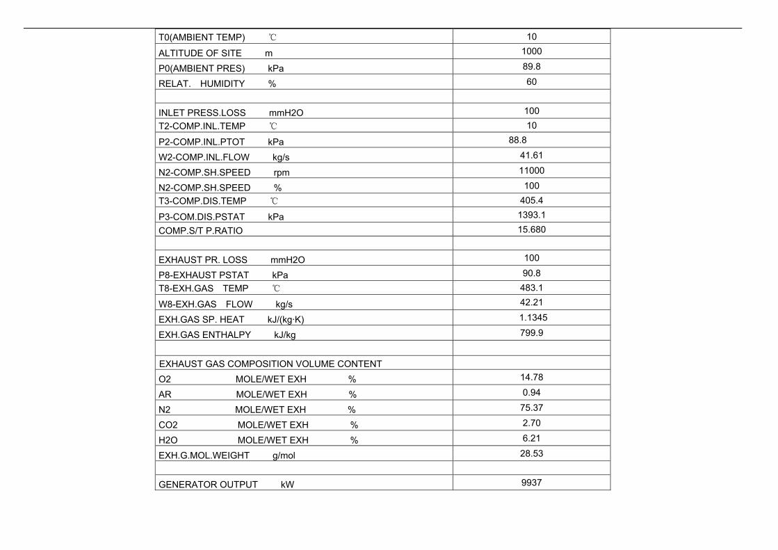
T0(AMBIENT TEMP) ℃ 10
ALTITUDE OF SITE m 1000
P0(AMBIENT PRES) kPa 89.8
RELAT. HUMIDITY % 60
INLET PRESS.LOSS mmH2O 100 T2-COMP.INL.TEMP ℃ 10
P2-COMP.INL.PTOT kPa 88.8
W2-COMP.INL.FLOW kg/s 41.61
N2-COMP.SH.SPEED rpm 11000
N2-COMP.SH.SPEED % 100 T3-COMP.DIS.TEMP ℃ 405.4
P3-COM.DIS.PSTAT kPa 1393.1
COMP.S/T P.RATIO 15.680
EXHAUST PR. LOSS mmH2O 100
P8-EXHAUST PSTAT kPa 90.8 T8-EXH.GAS TEMP ℃ 483.1
W8-EXH.GAS FLOW kg/s 42.21
EXH.GAS SP. HEAT kJ/(kg·K) 1.1345
EXH.GAS ENTHALPY kJ/kg 799.9
EXHAUST GAS COMPOSITION VOLUME CONTENT
O2 MOLE/WET EXH % 14.78
AR MOLE/WET EXH % 0.94
N2 MOLE/WET EXH % 75.37
CO2 MOLE/WET EXH % 2.70
H2O MOLE/WET EXH % 6.21
EXH.G.MOL.WEIGHT g/mol 28.53
GENERATOR OUTPUT kW 9937
GEARBOX*GEN. EFF % 96.34
FUEL MASS FLOW R kg/s 0.6485 FUEL INLET TEMPE ℃ 30
FUEL LOWER H.VAL kJ/kg 49452
ELECT. HEAT RATE kJ/(kW·h) 11618
ELECTRIC EFFIC % 30.99
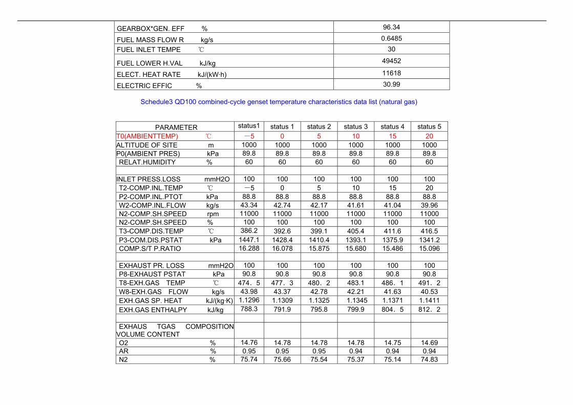
Schedule3 QD100 combined-cycle genset temperature characteristics data list (natural gas)
PARAMETER status1 status 1 status 2 status 3 status 4 status 5 T0(AMBIENTTEMP) ℃ -5 0 5 10 15 20 ALTITUDE OF SITE m 1000 1000 1000 1000 1000 1000 P0(AMBIENT PRES) kPa 89.8 89.8 89.8 89.8 89.8 89.8 RELAT.HUMIDITY % 60 60 60 60 60 60
INLET PRESS.LOSS mmH2O 100 100 100 100 100 100 T2-COMP.INL.TEMP ℃ -5 0 5 10 15 20 P2-COMP.INL.PTOT kPa 88.8 88.8 88.8 88.8 88.8 88.8 W2-COMP.INL.FLOW kg/s 43.34 42.74 42.17 41.61 41.04 39.96 N2-COMP.SH.SPEED rpm 11000 11000 11000 11000 11000 11000 N2-COMP.SH.SPEED % 100 100 100 100 100 100 T3-COMP.DIS.TEMP ℃ 386.2 392.6 399.1 405.4 411.6 416.5 P3-COM.DIS.PSTAT kPa 1447.1 1428.4 1410.4 1393.1 1375.9 1341.2 COMP.S/T P.RATIO 16.288 16.078 15.875 15.680 15.486 15.096 EXHAUST PR. LOSS mmH2O 100 100 100 100 100 100 P8-EXHAUST PSTAT kPa 90.8 90.8 90.8 90.8 90.8 90.8 T8-EXH.GAS TEMP ℃ 474.5 477.3 480.2 483.1 486.1 491.2 W8-EXH.GAS FLOW kg/s 43.98 43.37 42.78 42.21 41.63 40.53 EXH.GAS SP. HEAT kJ/(kg·K) 1.1296 1.1309 1.1325 1.1345 1.1371 1.1411 EXH.GAS ENTHALPY kJ/kg 788.3 791.9 795.8 799.9 804.5 812.2 EXHAUS TGAS COMPOSITION
VOLUME CONTENT
O2 % 14.76 14.78 14.78 14.78 14.75 14.69 AR % 0.95 0.95 0.95 0.94 0.94 0.94 N2 % 75.74 75.66 75.54 75.37 75.14 74.83

CO2 % 2.75 2.73 2.71 2.70 2.68 2.67 H2O % 5.80 5.89 6.02 6.21 6.49 6.87 EXH.G.MOL.WEIGHT g/mol 28.58 28.57 28.56 28.53 28.50 28.46 GENERATOR OUTPUT kW 10844 10528 10225 9937 9660 9210 GEARBOX*GEN. EFF % 96.53 96.47 96.40 96.34 96.28 96.17 FUEL MASS FLOW R kg/s 0.6890 0.6748 0.6613 0.6485 0.6361 0.6172 FUEL INLET TEMPE ℃ 30 30 30 30 30 30 FUEL LOWER H.VA kJ/kg 49452 49452 49452 49452 49452 49452 ELECT. HEAT RATE kJ/(kW·h) 11310 11412 11515 11618 11724 11929 ELECTRIC EFFIC % 31.83 31.55 31.26 30.99 30.71 30.18
Schedule4 QD100 combined–cycle genset 10℃load characteristics data list (natural gas)
PARAMETER status 1 status 2 status 3 status 4 status 5PAITIAL LOAD % 20% 40% 60% 80% 100% T0(AMBIENT TEMP) ℃ 10 10 10 10 10
ALTITUDE OF SITE m 1000 1000 1000 1000 1000 P0(AMBIENT PRES) kPa 89.8 89.8 89.8 89.8 89.8 RELAT. HUMIDITY % 60 60 60 60 60 INLET PRESS.LOSS mmH2O 100 100 100 100 100 T2-COMP.INL.TEMP ℃ 10 10 10 10 10 P2-COMP.INL.PTOT kPa 88.8 88.8 88.8 88.8 88.8 W2-COMP.INL.FLOW kg/s 29.49 29.50 30.91 34.92 41.61 N2-COMP.SH.SPEED rpm 11000 11000 11000 11000 11000 N2-COMP.SH.SPEED % 100 100 100 100 100 T3-COMP.DIS.TEMP ℃ 350.1 356.8 367.4 378.5 405.4 P3-COM.DIS.PSTAT kPa 891.2 934.7 1020.3 1166.7 1393.1 COMP.S/T P.RATIO 10.031 10.521 11.485 13.131 15.680 EXHAUST PR. LOSS mmH2O 100 100 100 100 100 P8-EXHAUST PSTAT kPa 90.8 90.8 90.8 90.8 90.8 T8-EXH.GAS TEMP ℃ 418.0 474.8 520.0 512.4 483.1 W8-EXH.GAS FLOW kg/s 29.78 29.86 31.36 35.45 42.21 EXH.GAS SP. HEAT kJ/(kg·K) 1.1048 1.1263 1.1439 1.1434 1.1345

EXH.GAS ENTHALPY kJ/kg 720.5 787.2 841.9 834.1 799.9 EXHAUST GAS COMPOSITION VOLUME CONTENT
O2 % 16.62 15.66 14.79 14.59 14.78 AR % 0.95 0.95 0.94 0.94 0.94 N2 % 76.02 75.68 75.38 75.31 75.37 CO2 % 1.86 2.30 2.69 2.78 2.70 H2O % 4.55 5.41 6.20 6.38 6.21 EXH.G.MOL.WEIGHT g/mol 28.64 28.58 28.53 28.52 28.53 GENERATOR OUTPUT kW 2340 3975 5962 7950 9937 GEARBOX*GEN. EFF % 92.17 93.90 95.09 95.82 96.34 FUEL MASS FLOW R kg/s 0.3152 0.3901 0.4809 0.5620 0.6485 FUEL INLET TEMPE ℃ 30 30 30 30 30 FUEL LOWER H.VAL kJ/kg 49452 49452 49452 49452 49452 ELECT. HEAT RATE kJ/(kW·h) 23983 17472 14359 12586 11618 ELECTRIC EFFIC % 15.01 20.60 25.07 28.60 30.99
3.2.1.5.5. Performance Curve
3.2.1.5.5.1. Temperature character
Environment temperature is the important signal of the unit operating mode. The variation of the environment temperature will affect the heat consumption and output
power of the unit observably. With the environment temperature increasing, the unit output power decreases markedly and the heat consumption increases markedly
The following picture lists the curve that the ouput power of QD100 gas turbine genset varies with the environment temperature changing from -40℃ to +50℃. The
curve is based on the environment pressure is 101.3KPA and the relative humidity keeps at 60%.

5000
6000
7000
8000
9000
10000
11000
12000
13000
14000
15000
-40 -30 -20 -10 0 10 15 20 30 40 50
大气温度℃
输出功率KW
10000
10500
11000
11500
12000
12500
13000
13500
14000
14500
15000
热耗KJ/KWh
输出功率
热耗
Curve-QD100 gas turbine genset performance target changing with environment temperature
3.2.1.5.5.2. Height character
On the conditions of environment temperature be held at 15℃ and relative humidity be held at 60%, the following curve shows the unit output power and heat loss varies
with the height above sea level.
The variety of the altitude will not affect the heat loss too much. However it influences the unit output power observably. The unit output power will decrease observably with
the altitude rising.

6000
7000
8000
9000
10000
11000
0 500 1000 1500 2000 2500 3000 3500
海拔高度M
输出功率KW
10000
10500
11000
11500
12000
12500
13000
13500
14000
14500
15000
热耗KJ/KWh
输出功率
热耗
QD100 output character change with altitude
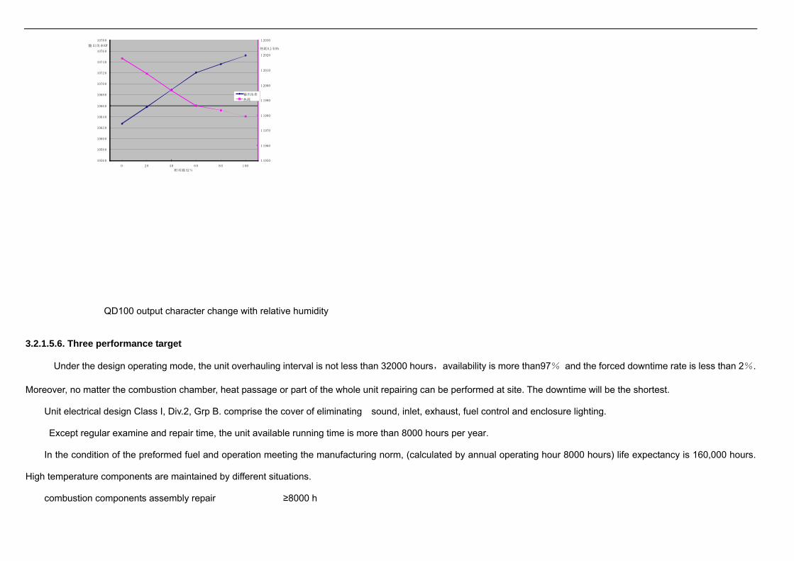
3.2.1.5.5.3. Humidity character
In a word, the changes of relative humidity will not influence the unit performance markedly. The increase of the relative humidity will enhance the unit output power and
decrease the heat loss slightly.
on the conditions of environment temperature be held at 15℃ and environment pressure be held at101.3Kpa, the following curve shows the unit output power and heat
loss varies with the relative humidity.
1 1950
1 1960
1 1970
1 1980
1 1990
1 2000
1 2010
1 2020
1 2030
10560
10580
10600
10620
10640
10660
10680
10700
10720
10740
10760
10780
0 20 40 60 8 0 1 00
热耗KJ/K Wh输出功率KW
相对湿度%
输出功率
热耗
QD100 output character change with relative humidity
3.2.1.5.6. Three performance target
Under the design operating mode, the unit overhauling interval is not less than 32000 hours,availability is more than97% and the forced downtime rate is less than 2%.
Moreover, no matter the combustion chamber, heat passage or part of the whole unit repairing can be performed at site. The downtime will be the shortest.
Unit electrical design Class I, Div.2, Grp B. comprise the cover of eliminating sound, inlet, exhaust, fuel control and enclosure lighting.
Except regular examine and repair time, the unit available running time is more than 8000 hours per year.
In the condition of the preformed fuel and operation meeting the manufacturing norm, (calculated by annual operating hour 8000 hours) life expectancy is 160,000 hours.
High temperature components are maintained by different situations.
combustion components assembly repair ≥8000 h

heat passage repair ≥16000 h
whole unit repair ≥32000 h
3.2.2. Heat Recovery Steam Generator
The exhaust heat boiler matched with QD100 gas turbine unit is a nonstandard product. The boiler is a horizontal type air flue, natural circuit and double pressure exhaust
heat boiler. The boiler has the following characters: Its flue gas completeness is good; heating power inside the boiler is homogeneous; heat deviation is small; flue gas
resistance pressure is low; exhaust heat is utilized sufficiently; the frame is fixed; mass center is rational; stability is good; it can resist typhoon and earthquake. For taking good
use of the gas turbine exhaust heat, the heat is utilized in graduate. The boiler also can take use of double pressure system. Medium temperature and medium pressure steam
generated by boiler enters the steam turbine to work. Low pressure saturated steam is used for deoxidization. Without high pressure heater, low pressure heater and oxygen
removal regeneration system, the output of the steam turbine can be improved. The gas turbine exhaust heat can be taken full use.
Under the Design condition:
The main parameters of the exhaust boiler :
Boiler shape: horizontal type, natural circuit
Gas turbine extraction flow 151.96 t/h
Gas turbine exhaust temperature 484.9 ℃
Medium pressure steam pressure 3.43 MPa
Medium pressure steam temperature 435 ℃
Medium pressure steam flow 16.95 t/h
Low pressure steam pressure 0.05 MPa
Low pressure steam temperature: saturation (supply for oxygen removal)
Low pressure steam flow 2.8 t/h

Boiler exhaust fume temperature 167 ℃
3.2.3. Turbounit
Matched with the steam flow of the exhaust boiler, a standard condensed steam type turbounit(type:N6-3.43) can be selected.
Main parameters of the steam turbine:
Rated power 6000 KW
Rated initial steam flow 25.4 t/h
Rated initial steam pressure 3.43 MPa
Rated initial steam temperature 435 ℃
Exhaust steam pressure 6.86 kPa
Specific steam consumption 4.2 kg/kWh
According to factual steam flow (16.95t/h) produced by the exhaust heat boiler, the output of the turbounit is 4005kW.
3.2.4. Main technical & economic target of the combined cycle unit
Under the Design condition:
One QD100 gas turbine genset, one exhaust heat boiler and one turbounit make up of one combined cycle power set. the main parameters are as follow:
QD100 gas turbine genset total output 9851 kW
Gas turbine generating heat efficiency 30.72 %
Turbounit total output 4005 kW
Combined cycle power set total output 13856 kW
Combined cycle generating heat efficiency 43.22 %

Combined cycle generating gas consumption 0.2358 M3/(kw·h)
Combined cycle gas consumption per hour 3267 M3/h
Annual operation hours 8000 h
Annual output of plant 11084.8 万kWh
House supply rate 5 %
Annual power supply 10530.6 万kWh
Combined cycle total capacity 15.0 MW
4. Fuel gas supply system
4.1. Fuel gas requirement
Natural gas used in gas turbine fuel is from natural gas tubing handling devices, the combustible engine electric enter pressure to import natural gas is 2.5±0.1 MPa (gauge
pressure), the temperature is 40 degrees ~ 50 degrees.
Natural gas components and impurities components in Schedule 5 and Schedule 6
schedule 5 Natural gas components
designation (V%)component thermal
value kJ/m3 H2 CO2 CH4 O2 iC4 CO N2 total
natural gas 1.2 0.05 98.00 0.2 0.10 0.05 0.40 100.0 35318
schedule 6 Natural gas impurities components
designation mg/SCM ppmv
total sul fur mercaptan H2S

impurities content
Fuel gas impurities: the average equivalent sphere diameter is not greater than 8~11 um, impurities total is not greater than 30 ppm.
4.2. Fuel gas supply system
Gas fuel source of the power plant is supplied by the first party. Supplier lines are embedded under ground. Gas supply pipe of the QD100 unit are embedded from the
compressor to unit pressure regulating device. Suggested Altogether there are two fuel gas processing unit. One fuel gas processing device is used for one unit. There is one
spare processing unit . Every fuel gas processing unit owns a oil vapor separator (to clean out a little liquid and foreign material in the pipe) and a condenser。After measuring
the nature gas ( it is the responsibility of the first party),it enter the fuel gas processing unit to compressed to 2.5Mpa,then go through the condenser and is separated by the
separator at the outlet of the fuel gas processing unit, at the end it enter the inlet system of the unit to supply ly gas fuel for the gas turbine genset.
Natural gas fuel operation is adopted, the Natural gas compressor technical indicators parameters are:
Largest design flow 4000 Nm3/h
Inlet pressure 5.0 kPa(G)
Inlet temperature 30℃
Exhaust pressure 2.8 MPa(G)
Exharst temperature 40℃
4.3. Natural gas component(mol percentage)
O2 15.0%
CO2 2.70%
N2 75.37%
H2O 6.21%

Exhaust mol quality 28.53 kg/mole
Exhaust specific heat 1.1350 kJ/kg·K
Exhaust enthalpy 802.0 kJ/kg
5. Cooling water system and compress air system requirement of the Combined-Cycle unit
5.1. Unit cooling water system requirement
The user offers cycle cooling water to cool for gas turbine powered generator units’oiling system, generator, stream turbine unit’condenser and auxiliary cooler.
To ensure the chilling effect of the generator, gas turbine lube oil system, the cooling water for the gas turbine auxiliaries is suggested customer set-up by two separate
water circulating pumps (one in operation, one standby). The backwater of the cooling water is combined to return pipe of the steam turbine recirculating cooling water. Then
flow to the forced ventilation cooling water to be used as cooling water circularly .
Main parameters:
flow of cooling water:
the flow of cooling water for the generator 100 t/h,
the flow of cooling water for the lube oil cooler 110t/h。
flow of make up waterfew,to be regardless by the manufactor
feed water pressure : 0.30 MPa
feed water temperature : ≯ 33 ℃。
requirment of water quality
transparent,pure,no granular sundries inside
pressure loss of cooler
cooler of generator : 3.3 kPa。
lube oil cooler : 30 kPa。
The cooling water of the steam turbine condensator and auxiliaries cooler is suggested provide by the circulating water system of the cooling tower with forced
ventilation device. build a 1500M3/h medium temperature cooling tower and a 200M3 closedcirculation pool. The volume of circulating water is about 1300M3/h; the
circulating cooling water temperature is not higher than 32℃ and the pressure is 0.3MPa.
The gas turbine generator、 lube oil system backwater of the cooling water is combined to return pipe of the steam turbine recirculating cooling water. Then flow to the
cooling tower circulating cooling water together.
5.2. combined cycle unit sweet-water demand
User offers sweet-water tanks to clean gas turbo-compressor and Heat Recovery Steam Generator.water press: 103 - 448 kPag.
5.3. Compress air requirement
Dry clean compressed air is required in unit work, the compressed air used in inlet filters back blow and in instrument wind must be clean (solid particles are not more than
5um), dry (liquid content is not more than 5ppm). Air largest consumption for the single unit is 0.5kg/s, gas pressure is 0.6~0.8MPa, temperature is not exceeding 75 degrees.
6. Drainage system
6.1. Requirement of the environmental protection department for the three waste treatment.
Environmental protection performs the following standards:
(1) Environmental air qulity is required according to the secondary class regulated in GB3095-1996《enviromental air qulity standard》.
(2) Fatory boundary noise level is performed according to GB12348-90《industrial organization factory boundary noise standard》. Environment noise level is performed
according to the third level regulated in GB3093-93《city area environment noise standard》.
(3) Oily soil water effluent standard is performed according to GL8978-88《waste water compositive effluent standard》.

6.2. Environmental protection governing measure
So far, gas turbine gensets have been installed and operated in many regions of china. Gas turbine genset itself has taken effective measure for environmental protection.
The power station pollutes and influences the ambience slightly. The main pollution source is the NOx and SO2 from the exhaust gas and the noise. Comparing with the coequal
size heat engine plant, its emission standard is much lower. Accompany with the further effective measure, the various emission can be decreased greatly. As a result, the power
station will be a environmental protection enterprise like a garden.
6.2.1. Exhaust fume treatment
QD100 gas turbine unit utilized the dry low emission(DLE)combustion technique can reduce the NOx and CO content of the exhaust effectively to meet the strict emission
requirement of the customer.
The estimate of the contaminant emission will be confirmed after the purchaser provides the impurity content of the fuel gas.
Usually, emission density of the various contaminant of the gas turbine unit is not high. It can meet the requirement in the 《heat engine plant air contaminant emission
standard》GB13223-1996.
6.2.2. Noise treatment
Noise source of the generating plant come from gas turbine, steam turbine, waste heat boiler and generator. The others normally are contributed by mechanical movement
which attenuate quickly and will not influence the ambience.
Air inlet, exhaust and mechanical noise contribute to the gas turbine noise. So the silencer is installed at the inlet and exhaust port. And the sound insulation enclosure is
designed for eliminating mechanical noise. The noise is less than 90dB(A) one meter from the unit.
Moreover, the principal machine is arranged at the place that will influence the central office slightly. Forest is planted in the factory to absorb the noise.
7. Supply scope
7.1 QD100 Gas turbine genset Supplyc contents

Single set QD100 Gas turbine genset Supplyc contents
Serial number
Components number
name number note
1 GE10-1 Gas turbine 1
2 AC generator 1
3 reducing gearbox 1
4 flexible lamination coupling 1
5 QD100.1 air inlet filtering and noise elimination system 1
6 QD100.2 AC generator pedestal 1
7 QD100.3 generator enclosure 1
8 QD100.4 shield of low speed coupling
1
9 QD100.5 oil system 1
10 QD100.6 gas turbine enclosure 1
11 QD100.7 anti-surge bleeding system
1
12 QD100.8 compressor cleaning system 1 optional 13 QD100.9 water cooling system 1
14 QD100.10 starting system
1
15 QD100.12 shield of high speed coupling
1
16 QD100.13 gas turbine pedestal 1
17 QD100.14 exhausting system 1 18 QD100.15 CO2fire fighting system 1 19 QD100.16 enclosure ventilation system 1
20 QD100.17 gas fuel system 1
21 QD100.18 draining system 1
22 QD100.19 Walk ladder (left) 1
23 QD100.20 walk ladder (right) 1
24 QD100.21 local control room 1 optional
25 QD100.25 high voltage electrical system 1 The electric parts

Serial number
Components number
name number note
26 QD100.26 MCC 1 interface: high voltage
interface for generator
circuit breaker into line
terminals, low voltage
and dc power interface
for supplier into line
terminals. Low voltage
power supply into line
shall be five line
system, pick up all the
way 400kW frequency
conversion motor, all
the way after 200kW
motor control center.
Gas turbine ontology
and auxiliary system
internal all cables and
pipelines and stent by
the supplier delivery
27 QD100.27 unit lighting system 1
28 QD100.28 ground protection system 1
29 QD100.29 DC electrical system 1
30 QD100.30 auxiliary Measure control system 1 31 QD100.31 control system 1
7.1.1. GE10-1 gas turbine include:
·inlet upturned inlet casing
·axial flow compressor with IGV
·reflux can burner module
·heavyduty efficient turbine

·2 vibrating sensor
·rotor speed sensor
·thermocouples for gas turbine temperature measure
7.1.2 Steel structure baseplates for installing gas turbine, generator, gearbox and accessories
7.1.3 Frequency conversion motor start system
7.1.4 Gas fuel(natural gas)system
·gas fuel filter
·gas feed pressure regulator valve
·velocity ration control valve
·stainless steel gas fuel piping after the filter
·dust removal and purify device for gas fuel
7.1.5 Lubricating oil system for gas turbine, gearbox and generator
·oil tank module
·main oil pump driven by gearbox
·auxiliary oil pump driven by AC motor
·emergency oil pump driven by DC motor
·dual oil filter and manual operation valve
·oil pipe
·pressure regulating valve, temperature regulating valve and water cooler
·instruments and the necessary protection devices
·oil mist separator at the oil tank vent port
7.1.6 Reduction gear box and coupling

·planet reduction gear box, output speed 3000rpm/r
·lamination flexible coupling for connecting gas turbine and gearbox
·lamination flexible coupling for connecting gearbox and generator
·shield of coupling
·gearbox vibration sensor
·gearbox thermocouple
7.1.7. Sound insulation enclosure mounted on the baseplate, include gas turbine enclosure and generator enclosure
·painted carbon steel constructure
·employee in and out door
·gate for gas turbine dismounting and maintenance
·flame detector
·gas density detector
·CO2 fire fighting line and spray cup
·sound and light crossing-signal for extinguishant release
·ventilation baffle of the enclosure(operated by nitrogen)
· gas turbine enclosure ventilation system, include intake air port, silencer, exhaust blower and exhaust silencer driven by 2 AC motors at the exhaust port
7.1.8. Inlet system
·impulse selfpurging inlet filter device with 180 filter elements, supported by carbonsteel bracket
·free air diffuser,join the filter house and gas turbine inlet casing, composed of flexible link, built up connection piece, elbow and silencer
·blowback device
7.1.9 exhaust system

·expansion joint, changeover portion and gusset flange
7.1.10 CO2 fire fighting system
·CO2 bottles (two group)
7.1.11 Alternator and electrical equipment
·brushless ( 6.3kV ) 10.5kV alternator,speed 3000rpm
·water cooler
·brushless excitation system
·2 vibration sensors on generator shaft shell
·battery, group charger and alternating current distribution panel
·MCC
·high voltage switch cabinet , instrument cabinet
7.1.12 Control system
Control system is installed in local control room, it include:
(1) MARK VI processor with the following functions :
·control and protect for gas turbine genset
·state monitoring
·alarm
·fire and gas monitor
·vibration monitor
·generator integration control
·serial data port(RS232 standard industry bus)
(2) gererator control panel with the following functions:
·manual and automatic synchronization
·generator protect
(3) excitation control panel
·auto voltage regulator(A.V.R)
·generator excitation control
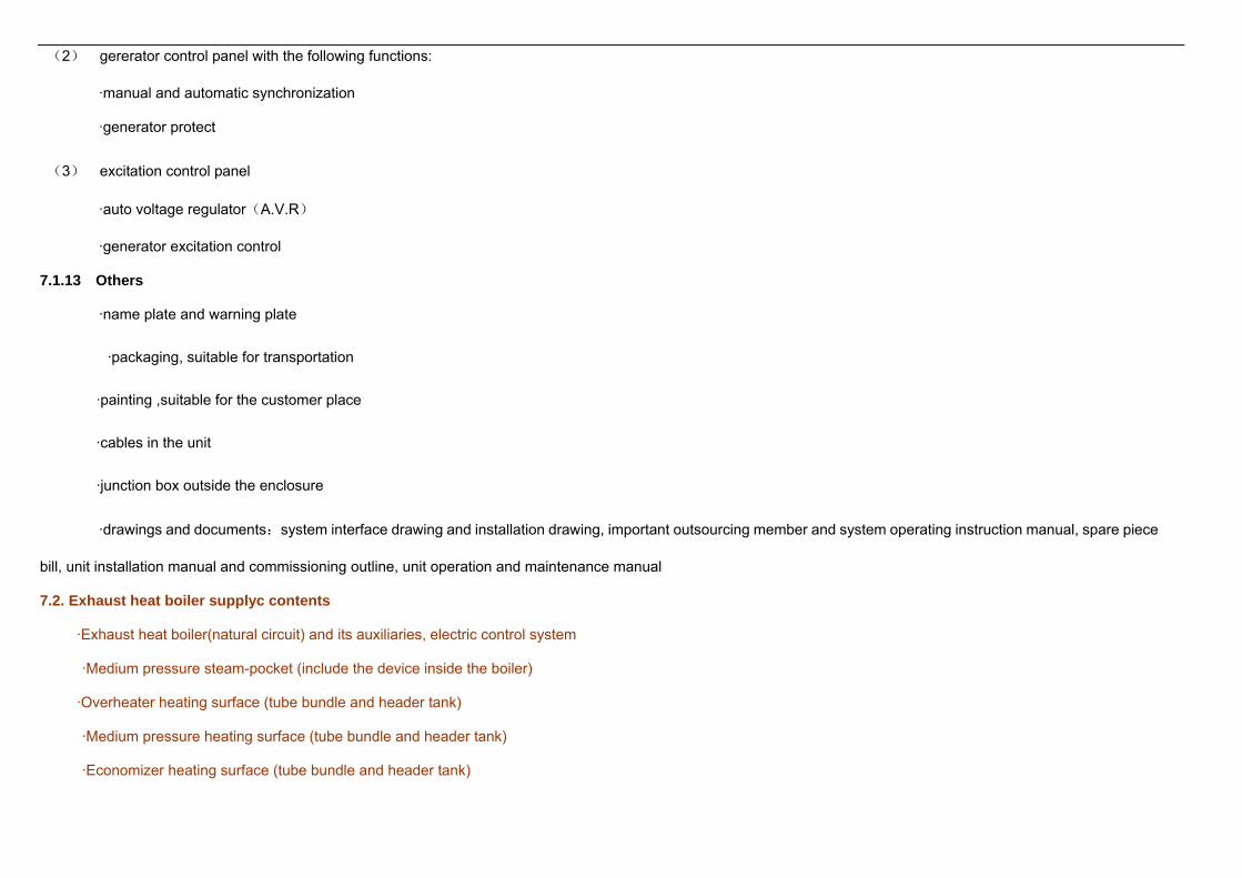
7.1.13 Others
·name plate and warning plate
·packaging, suitable for transportation
·painting ,suitable for the customer place
·cables in the unit
·junction box outside the enclosure
·drawings and documents:system interface drawing and installation drawing, important outsourcing member and system operating instruction manual, spare piece
bill, unit installation manual and commissioning outline, unit operation and maintenance manual
7.2. Exhaust heat boiler supplyc contents
·Exhaust heat boiler(natural circuit) and its auxiliaries, electric control system
·Medium pressure steam-pocket (include the device inside the boiler)
·Overheater heating surface (tube bundle and header tank)
·Medium pressure heating surface (tube bundle and header tank)
·Economizer heating surface (tube bundle and header tank)

·Low pressure steam-pocket (include the device inside the boiler)
·Low pressure heating surface (tube bundle and header tank)
·Framework, chamber wall
·inlet combustion flue,、main fume stack(linkingup with expansion joint)
·control instrument in the scope of boiler
·Control panel on site
·Medium feed pump
·Subpressure feed pump
·Device for adding drug
·Blow down diffuser
7.3. Steam turbine part supplyc contents
·turbounit(standard condensed steam type),model:N6-3.43, its auxiliaries and electrical control system
·Steam turbine, enclosure, mounting
·Steam turbine door and hanging bracket
·Water purifier, oilfilter, steam strainer
·Steam turbine oil pump and self start-up device
·Oil tank cooler
·Condensator
·High pressure heater, low pressure heater
·Four stage emanation, air removal jet
·Piping line and instruments, electric appliance, thermometer
·Steam turbine generator:6000KW 3000 rpm 10.5KV
7.4. exclusion part
7.4.1.:the following item is not in the CAGT supply scope:
The following systems are options, and don’t include the goods that are supplied by CHINA AVIATION GAS TURBINE COMPANY., LTD., but they can be afforded in repay.
7.4.1.1.Compressor off-line scavenger system(option)
7.4.1.2. Exhaust part(option)
exhaust elbow、 silencer 、 Wye flapper valve 、chimney and steel bracket
7.4.1.3. Electrical part(option)
·DCS control system(centralization of control)
·House transformer and its electrical conduit system
local control room house
7.4.2. The following item is not in the CAGT supply scope:
·Suggested operation spare parts
·Citywork and city planning work
·Transport from delivery site to field
·Drain and exhaust air pipe of gas turbine
·The outside pipe of enclosoure of compressor air system
·The cable and cable trays and cable canal in the outside of Gas turbine
·Field facility
·Fuel storage and treatment
·Gas turbine fuel

·Lube oil charging for the first time
·Consumable material during the installation ,completion and operation
·Common resource about power supply ,water and compressed air
·disassembly and assembly sling for unit maintenance
·lube for unit commissioning and operation
·Floor space
·Factory lighting
·Other training except supply scope
·The expenses for customer review and test
·Investigation of the third party
7.5. Supply scope interface
7.5.1. Fuel gas system
1m of unit enclosure inside,natural gas pipe
7.5.2. Compressor air system
compressor air inlet flange of blowback device in the inlet filter room , compressor air connect flange of washing skid, air compressor and air store tank
7.5.3. Air enhaust and drain system
The interface of air enhaust and drain system in turbine base plate and enclosure
7.5.4. Cooling water system
The inlet and outlet flange of cooler in gas turbine lubrication system and generator
7.5.5. AC generetor

The breaker outlet of switch cabinet
8. Design、manufacture and accept standard
QD100 gas turbine genset during the packaged design, the working standards adopt the associate national standards and aerial standards. Trade standards introduce the
RP11PGT 《gas turbine package》 and relative API standards. In the case of no standard can be applied, the enterprise standards will be specified.
Boilers are national conrrespond standard, corollary equipment and parts meet enterprise standard. Some main standards are listed below:
GB10489-89 aero modified gas turbine general technical requirements
GB/T15736-95 gas turbine accessories technical conditions
JB/T7074-93 gas turbine generator general technical conditions
GB50193-93(1999 edition)CO2 fire fighting system design specifications
GB50205-2001 steel structure engineering construction and accept specifications
GB50235-97 industry metallic pipe engineering construction and accept specifications
GEI41040g gas fuel specification
GEI41047k liquid fuel specification
SOM17366-A-5 oil specification
SOM45055-A-2 gear box specification
GB12348-90《industrial organization factory bound noise standard》
JB/T6696-1993 power station boiler technical condition
DL647-1998 Test rules of power industry boiler pressure vessel
JB/T1609-93 boiler cylinder technical condition of manufacture
JB/T1611-1993 Boiler pipe’s technical condition of manufacture

JB/T1620-1993 Boiler steel construction’s technical condition of manufacture
Boiler heat calculation meets standard method of boiler unit calculation
Intensity calculation meets the intensity calculation of hose boiler press module
Smoke and wind resistance calculation meets standard method of boiler aerodynamic calculation
9. Manufacturing cycle aircraft crew
After feasibility research report is approved and all the investor signed the contract, the technical and the commercial negotiation of the main equipments order will be
carried out immediately. The contract will be signed. Meanwhile preliminary design will be performed. Working plan will be completed based on the job above. Usually for a
combined cycle power plant, 12 months later from starting, the combined cycle power genset can be put into operation.
10.after service
10.1. installation and commissioning give instruction service
CAGT can provide installation、commissioning and reliability operation service for QD100 gas-steam combined cycle power set or send professional technician to give
instruction on site.
Field-service contents include:
(1). Basic maijian in advance, seller dispatches one engineer, the working life is 1.0 month
(2). Equipment installation, seller dispatches one senior engineer, the working life is 2.0 months, two electric controlled senior engineers,2.0 months.
(3). Equipment debugging, seller dispatches two senior engineers, the working life is 2 months, one engineer from gas turbime company, 2 months.
10.2. Customer training
CAGT provides a complete set of training service of the QD100 gas-steam combined cycle unit for operators and maintenance. CAGT has compiled a complete set of
training material for the customer. Fulltime professional trainers are responsible for teaching relative course. The training way include three modes: CAGT plant training, scene
training and product manufacture review.

10.2.1. CAGT plant training,
according to the training material, introduce the integral structure, include the unit constitutes, unit performance, unit working theory and function introduce of each system
and factory training、 introduce the attentive items about unit transportation and storage. The above training will occupy 6 working days. Vendee can decide the number of
persons who take part in training and pay themselves.
10.2.2. Site training
introduce the attentive items about the unit operation and running; the whole operation course from the unit start to normal shut down. The training is performed according
to the operation criterion which explains the operation steps of each stage in detail. It includes: each system state check before start; start and accelerate process; stable
empty/full load, rated speed operate process; increase/decrease load and parallel in/ stand alone process; shutdown cooling process and check after shutdown. trouble shooting,
record, emergency shutdown treatment are also include. The course above can be arranged in 6~12 working days.
My company also offers corresponding technically training about exhaust-fired Steam Generator. Training contents are synchronal to progress of works. We arrange 2
workoing-times courses.
The vendee pays for the flied-training sevice to CHINA AVIATION GAS TURBINE COMPANY according to sevice standard.
10.2.3. overview the production plan
It is an important step to overview the production plant and the product customer to enhance the knowledge of the product. CAGT can provide all the information and
service for the customer to know about the product quality and the production condition. According to the customer requirement, CAGT can provide the following service: to
visit QD100 Gas-Steam Combined-Cycle Power genset each part production plant (Italy NP company). The cost is payed by vendee themselves.
In addition, if vendee demands more detailed training or requires to train in GE Company, the two sides can make another agreement.
10.3. quality assurance stage
In quality assurance stage CAGTC will who offer necessary technological service.
In quality assurance stage CAGTC will offer instead spare parts in the fastest speed
CAGTC will call at vendee aperiodically, help to increase running attention level, answer technological questions, and introduce the equipment improvement situation.
10.4. Toll technological service of CAGTC
About the following technological service CHINA AVIATION GAS TURBINE COMPANY should make addition agreements with vendee.
10.4.1. installation and debugging service for QD100 Gas-Steam Combined-Cycle Power genset.
According to customer requirement and mutual contract, CAGT can provide installation and debugging project service for QD100 Gas-Steam Combined-Cycle Power
genset.
10.4.2 repair service
According to customer requirement and mutual contract ,CAGT can provide examine and repair, overhauling service for QD100 Gas-Steam Combined-Cycle Power
genset. Mainly include schedule repair and nonscheduled repair on site:
(1) combustion chamber inspect and repair(minor overhaul)
(2) heat passage inspect and repair(medium repair)
(3) the whole unit repair(complete overhaul)
(4) nonscheduled overhaul for faults eliminating

10.4.3. technical consultation service
CAGT product service center owns professional service person of various specialties. They can explain many kinds technology issues about gas turbine unit and provide
high level technical consultation service, include power plant build, invest analyse, technique feasibility report, unit operation status analyse, fault analysis, fault diagnosis and
treatment. For all of the above service,the technicians can go to site
11. an attached or enclosed graph
QD100 gas turbine genset assembly drawing.
QD100 gas-steam combined cycle genset factory floor plan
QD100 gas-steam combined cycle genset _thermodynamic system illustrative diagram
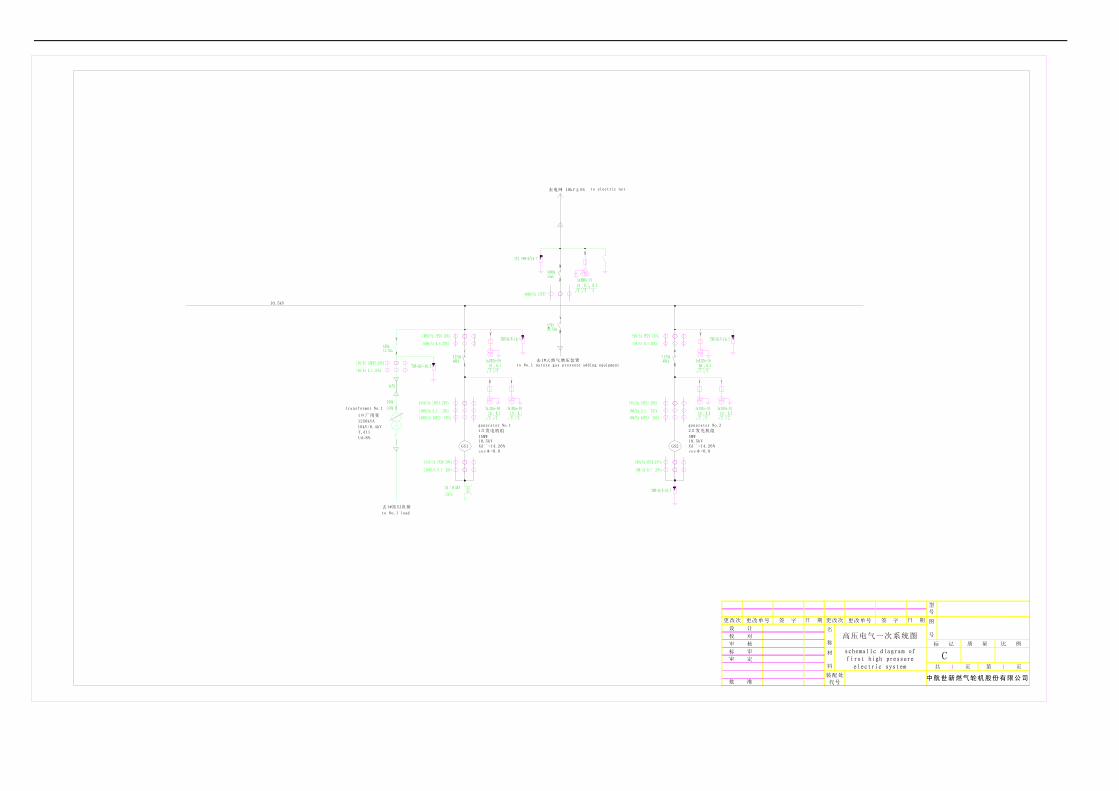
QD100 gas-steam combined cycle genset-high voltage system diagram

dimension benchmark :axial direction dimension is left end-face of generator seat in the main-view,side dimension is center line of base seat in the planform,height dimension is low plane of platform for gas turbine power plant(see 0 point label); gas turbine power plant included case inlet system exhaust system (according to original technic instruction,except chimney) 、there should be paint of using H06-02 paint twice then using H04-1 paint twice on surface of case ventilation system and so on , all kinds of pipeline(except stainless steel pipeline) according to GB7231-87"industry pipeline distinguish from colour and distinguish from symbol " to perform .
transformer
collocation drawing ofcontrol room
liquid fuel system
nitrogen replacement system
drain system
right ladderleft ladder
QD100A integer collocation drawing
air compressed system
fuel system
case ventilation system
CO2 fire fighting system
exhaust system
gas turbine seat
GE10-1engine hood for high speed coupling
high speed coupling
gear boxstart system
antisurge exhaust systeminlet filter and noise elimination system
hood for low speed coupling
cooling water system
air compressor washing system
gas turbine case
lube system low speed coupling
QFRW-15-2
generator 10.5KV)
generator case
generator seat
原用图号
底图总号
代替图号
签字及日期
旧底图总号
序号 增加序号
设表02
装配处
代号批 准
校 对
审 核
标 审
审 定
设 计
更改次 日 期 更改单号 签 字
名
称
材
料
更改次 更改单号 签 字
重 量
第 页
日 期
项 目 号
共 页
图
号
型
号
比 例
QD100A总体布置图
C1 1
二氧化碳灭火系统
I G
空压机压缩系统
1
2
3 54 6 7 8
9101112131415
厂变压器
液体燃料系统
氮气置换系统
液体燃料进口
气体燃料进口
雾化空气进口
mm
尺寸基准:轴向尺寸为主视图中发电机底
座左端面,侧向尺寸为俯视图底座中心线,
高度尺寸为机组底座底平面(见图中0点标注);
机组构件其中包括箱装体、进气系统、
排气系统(其中烟囱除外,按原技术条件)、
箱体通风系统等外表面均应保持涂H06-02铁
红环氧树脂漆两遍后涂H04-1冰灰色氟碳漆两
遍,按采购部门的色标板统一控制颜色效果。
各种管路(不锈钢材料管路除外)
按GB7231-87"工业管路的基本识别色和识别符号"执行。
X
mm
右走梯
0X
Y
0
左走梯
启动系统
就地控制间布置图
冷却水系统
排污系统
防喘放气系统
燃料系统
压气机清洗系统 高速联轴器罩壳高速联轴器
进气过滤消声系统 发电机底座 发电机箱装体
QFRW-15-2发
电机(10.5KV)
TDP8-6600-00T15(Z)
低速联轴器
低速联轴器罩壳
润滑系统 燃机箱装体
PF65D
齿轮箱GE10-1发动机 燃机底座 排气系统
箱体通风系统

天然
气压
缩机
567
mai
n en
tranc
e of
th
e pl
ant
s team turbineboiler
cutlineQD100 gas turbine unitbuilding
水处理间 water treatment room
循环水冷却塔 cycling water cooling tower7 612
131313
13
14
12
冷却器 cooler
循环水集水池 cycling water pool11
天然气出口分离器 natura l gas separator
消防、循环水联合泵房 fire fighting and cycling water combine pump room
8
日 期更改次 更改日期 签 名
第 页共 页
比 例重 量
图
号
型
号
材
料
名
称
批 准
审 定
标 审
审 核
校 对
设 计
签 名更改日期更改次 日 期
项 目 号
批 准
装配处
代 号
3
余热锅炉
10
汽轮机
9
4
10
11
0X
Y
2
北 north
设计单位:米 design unit : m
室外构筑物 outdoor erection
图例
建筑物 erection
地下构筑物 erection underground道路 road绿地 greenbelt
8
电气楼 electric building
污水处理池 sewage treatment pool
7
6
升压站 pressure adding station
天然气压缩机 natural gas compressor5
4
QD100燃气轮机发电机组
3
2
综合楼
说明
1厂区
主入口
5
1
149
3# QD100燃气-蒸汽联合循环发电机组
天然
气压
缩机
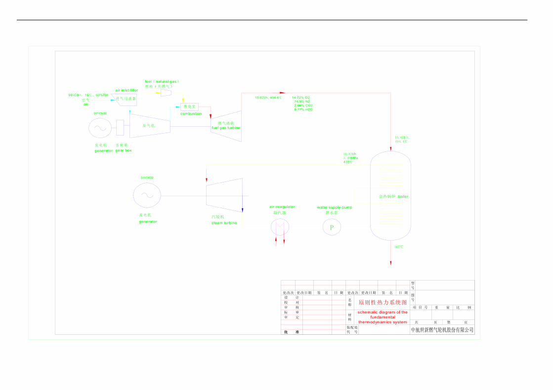
16.82t/h3.43MPa435℃
14.72% O2 74.9% N2 2.66% CO2 6.77% H2O
15.62t/h, 494.4℃
第 页
图
号
项 目 号 重 量
共 页
比 例
型
号
P
凝汽器
air coagulator供水泵
water supply pump
签 名更改次
名
称
日 期
材
料
装配处
代 号
更改日期更改日期
批 准
更改次
设 计
校 对
审 核
标 审
审 定
批 准
签 名
原则性热力系统图
日 期
167℃
schemalic diagram of the fundamental
thermodynamics system
余热锅炉 boiler
进气过滤器
air inlet filter燃料(天燃气)
fuel(natural gas)
燃气涡轮fuel gas turbine
齿轮箱
压气机
4005KW
gear box
燃烧室
combustion
空气
98%CH4,15℃,60%RH
9713kW
发电机
generator
air
汽轮机
steam turbine
发电机
generator
15.62t/h, 494.4℃
cosφ=0.8
2#发电机组
5MW10.5kVXd``=14.26%GS2
generator No.2
去电网 10kV±5% to electric net
to No.1 load
generator No.1
transformer No.1
to No.1 nature gas pressure adding equipment
10kV/0.4kV
Ud=8%
Y,d11
1250kVA
去1#站用负荷
去1#天然气增压装置
10.5kV
GS1 Xd``=14.26%10.5kV15MW
1#厂用变
1#发电机组
cosφ=0.8
schemalic diagram of first high pressure
electric system
中航世新燃气轮机股份有限公司
C
标 记
装配处
代号
质 量
1
比 例
第 页
型
号
1
校 对
审 核
标 审
设 计
批 准
审 定
名
称
材
料
日 期 更改次更改单号更改次 签 字 签 字更改单号 图
号
日 期
共 页
高压电气一次系统图

天然气压缩机
2# QD100燃气-蒸汽联合循环发电机组
3# QD100燃气-蒸汽联合循环发电机组
914
1
5
厂区主入口
1
说明
综合楼
2
3
QD100燃气轮机发电机组
4
5 天然气压缩机 natural gas compressor
升压站 pressure adding station
6
7
污水处理池 sewage treatment pool
电气楼 electric building8
绿地 greenbelt道路 road地下构筑物 erection underground
建筑物 erection
图例
室外构筑物 outdoor erection
设计单位:米 design unit : m
北 north
2
Y
X0
11
10
4
9
汽轮机
10
余热锅炉
3
装配处
代 号批 准
项 目 号
日 期更改次 更改日期 签 名
设 计
校 对
审 核
标 审
审 定
批 准
名
称
材
料
型
号
图
号
重 量 比 例
共 页 第 页
签 名更改日期更改次 日 期
8
5
5
消防、循环水联合泵房 fire fighting and cycling water combine pump room
天然气出口分离器 natural gas separator
11
循环水集水池 cycling water pool
冷却器 cooler
12
14
13
13 13 13
12
6
7
7
6
天然气压缩机
6
天然气压缩机7
循环水冷却塔 cycling water cooling tower
水处理间 water treatment room
buildingQD100 gas turbine unit cutline
boilersteam turbine
mai
n en
tranc
e of
th
e pl
ant
3
4
0X
Y
2


![Gas and Steam Cycles, Steam Turbines 3 [Compatibility Mode] (HITAM PUTIH)](https://img.dokumen.tips/doc/110x75/55cf92db550346f57b9a161a/gas-and-steam-cycles-steam-turbines-3-compatibility-mode-hitam-putih.jpg)