Embed Size (px)
Citation preview

QCOM v1.x EGM Communications Interface and LAN Requirements (Clubs and Hotels) Version 2.2

EGM Communications Interface and LAN Requirements Version 2.2 2 of 29
© The State of Queensland (Department of Justice and Attorney-General) 2014. Copyright protects this publication.
The State of Queensland has no objection to this material being reproduced but asserts its right to be recognised as
author of its original material and the right to have its material remain unaltered. Enquiries should be addressed to
The information contained herein is subject to change without notice. The copyright owner shall not be liable for
technical or other errors or omissions contained herein. The reader/user accepts all risks and responsibility for
losses, damages, costs and other consequences resulting directly or indirectly from using this information.
For further information, please contact the Office of Liquor and Gaming Regulation on 13 QGOV (13 74 68)
or visit www.olgr.qld.gov.au

EGM Communications Interface and LAN Requirements Version 2.2 3 of 29
Contents
1 Introduction 4
2 Overview 6
3 Historical Information 7
3.1 The Old EGM Communications Interface 7
3.2 The Old EGM LAN 8
3.3 Other Information 8
4 EGM Protocols 9
5 The EGM RS-232 Interface 10
5.1 Physical Interface 10
5.2 Electrical Interface 11
6 EGM FO Interface Mounting 12
7 The EGM 240VAC FO Interface Power Supply 13
8 EGM Fibre Optic Interface Card Specifications 14
8.1 General 14
8.2 Dimensions and Mounting 16
8.3 The FO Interface Card RS-232 Port 17
8.4 FO Interface Power Connector and Fuses 18
8.5 Fibre Optic Transceivers 18
9 The EGM Local Area Network 21
9.1 The EGM FO LAN 21
9.2 Fibre Optic Cable types 22
9.3 Deleted – Site Cabling Diagrams 22
9.4 Fault Finding Fibre Optic EGM Loops 22
10 Third Party EGM LAN Access 24
10.1 General Requirements for Methods of Tapping EGM Communications 24
Appendix A 26
Revision History 28

EGM Communications Interface and LAN Requirements Version 2.2 4 of 29
1 Introduction Policy All gaming machines in the Queensland clubs and hotel market must be connected to an Electronic Monitoring System and communicate using the same communications protocol, communications interface and LAN. The intent in standardising the EGM LAN is to minimise costs, for example when a gaming venue wishes to switch LMOs. Purpose The purpose of this document is to publish the minimum technical requirements for the following items:
- The EGM Communications Interface used for the basic monitoring service. - The EGM LAN used for the Basic Monitoring Service.
This document also provides general information regarding EGM LANs in Queensland Clubs and Hotels. Scope This document is generally applicable to Queensland licensed EGM manufacturers, Licensed Monitoring Operators (LMOs), licensed repairers and third parties wishing to interface to the EGM LAN. Requirements for EGMs in this document apply only to QCOM v1.x EGMs for the Queensland clubs and hotels market. This document refers to “loops”. This refers to the EGM fibre optic LAN loops running the OLGR EGM Protocol “QCOM” version 1.x. There may be additional gaming related networks in a venue running other services. These requirements do not apply to those other networks.
Responsibilities
The EGM manufacturer is to supply the EGM Communications Interface (including the FO Interface card) with QCOM v1.x EGMs sold in Queensland. Licensed repairers are responsible for installing and maintaining the LAN (as contracted) as a QCOM v.1x LAN is comprised of regulated gaming equipment.
EGM Communications Interface and LAN Requirements Version 2.2 5 of 29
Glossary Site Controller
A Site Controller is a device (often PC based) local to the gaming venue and is a part of the LMO monitoring system. It is a QCOM master (polling) device which collates EGM meters and events en-route for the host system. For more information refer to OLGR Site Controller Minimum Requirements and QCOM Site Controller Operating Procedures documents.
Abbreviations EGM Electronic Gaming Machine FO Fibre Optic HCS Hard Clad Silica (fibre optic cable type) IGT The EGM manufacturer LAN Local Area Network LMO Licensed Monitoring Operator (refer Queensland Machine Gaming Act 1991) OLGR Queensland Office of Liquor and Gaming Regulation

EGM Communications Interface and LAN Requirements Version 2.2 6 of 29
2 Overview There are two communication interfaces in a QCOM v.1x EGM which are specified by this document. They are cascaded together. Starting at the EGM’s CPU, the first specified interface is a RS-232 interface (refer section 5 for details). The EGM RS-232 interface plugs into the second specified interface, which is the EGM’s Network Interface Card (also known as the Fibre Optic (FO) Interface Card). This card’s outbound interface is plastic or HCS optical fibre (not glass). Refer section 8 onward for FOI specifications. QCOM EGMs are not bound to use a fibre optic communications interface and LAN, this is a Queensland club and hotel specific requirement and in other markets, any RS-232 compatible interface may be utilised.
The fibre optic communications interface on the EGM’s interface card is via the “Versatile Link”TM
fibre optic connection system (or equivalent). This is a compatible interface as used currently throughout Queensland Clubs and Hotels in the EGM fibre optic communication system operating the old I.G.T. EGM communications protocol at 9600 baud and the OLGR QCOM v1.x protocol operating at 19.2k baud on the same interface and LAN. The two protocols can co-exist on the same LAN at different baud rates. The EGM manufacturer supplies gaming machines with the RS-232 connector, a 240VAC connector and mounting studs for the addition of the fibre optic interface card also supplied by the EGM manufacturer. The EGM LAN must be cabled according to OLGR requirements and specifications in this document to allow easy switching between licensed monitoring operators without having to re-cable the LAN. This means for the Basic Monitoring Service only the LMO's Site Controller equipment will have to be changed in order to switch operators. However, if the venue changing LMOs has any other value added services through their current LMO (e.g. a player loyalty system) then they will probably have to be changed also in order to switch LMOs
EGM Communications Interface and LAN Requirements Version 2.2 7 of 29
3 Historical Information LMOs, repairers and third parties in the past may have required the following background technical information concerning interfaces on older EGMs and EGM LANs which was in use prior the introduction of LMOs in Queensland. However as all the hardware described in this chapter should now be gone from Queensland licensed gaming venues, this section is no longer required reading.
3.1 The Old EGM Communications Interface
This old interface was specific to older EGMs which operated the I.G.T. Communications Protocol (of which none should now remain in operation). The interface was similar to the new interface in that there is an RS-232 cable connected to a fibre optic interface card. (Note, an EGM may have its software upgraded to QCOM with having to upgrade the interface, as the old hardware was forwardly compatible.) The differences between the current and old RS-232 interface are as follows. The physical RS-232 interface connector at the EGM was via a 5-circuit MOLEX Single Row Connector, Series 70066G. Pins are Box Female Crimp Terminal Series 70058G.
Pin 1 is Not Connected (NC), Pin 2 is EGM Tx, Pin 3 is NC, Pin 4 is EGM Rx, Pin 5 is Ground.
The interface was in accordance with RS-232 specifications. The RS-232 interface is located near four mounting studs for the connection to an old IGT fibre optic interface card mounted on the studs, the studs are the same as for the current interface. The old IGT FO Interface card differs from the new FO Interface Card in the following ways. The 240V connector to the IGT FO interface card was via a 2 Way AMP MATE N LOK plug (AMP Part 1-480698-0) with male pins to suit. There was also a M4 x 10mm earth stud to earth the FO Interface card to its back plane. The IGT FO interface was also a FO repeater as per the new FO Interface cards but used the older Versatile Link FO system which utilised: 1 x High Performance 1M baud Transmitter (HFBR-1522) 1 x High Performance 1M baud Receiver (HFBR-2522) The IGT interface cards have been verified to operate at speeds up to 115.2K baud. However, there is no guarantee existing EGM FO LANs will operate at speeds any higher than 9600 baud without first testing at the higher speed and possibly making some adjustments to the existing cabling to ensure the FO cable has been laid within tolerances for a higher speed. The old interface FO transmitter/receivers are forwardly compatible with the new FO transmitter/receivers. (i.e. the old FO interface cards can talk to a new FO interface card and vice versa)

EGM Communications Interface and LAN Requirements Version 2.2 8 of 29
3.2 The Old EGM LAN
The old EGM LANs consisted of fibre optic loops with up to 64 EGMs per loop. The loops terminated at various points throughout the venue inside an EGMs console (where the cash box is located), where the now long obsolete IGT Site Controller was located. This Site Controller was called an LCOM, short for Location COMmunicator. Each LCOM Site Controller had a 240V mains power connection via an IEC connector and a standard phone line connection (dial-in only). Occasionally a stand-alone IGT FO interface was used as a booster repeater for very long cable runs. (Note, the new FO interface card has a much greater range and a booster is rarely needed.) Ownership of all the old IGT fibre optic interface cards and all the fibre optic cable was given to the venues by the OLGR.
3.3 Other Information
It should also be noted that a small number of the old IGT Game King
TM EGMs used a custom
built-in FO interface card. This card differed from the standard IGT FO interface card in the following ways: - It used the Low Current/Extended Distance 40K baud FO Transmitter (HFBR-1533i).
However, IGT have advised OLGR (6th June 1997) that they are changing to the HFBR-1522 FO Transmitter on all new IGT Game King FO interface cards supplied and fitted in I.G.T. Game King EGMs.
- There is no easily accessible 240V power connector, RS232 connector or mounting studs. This makes it difficult to tap into the EGMs RS-232 signal because there is none readily available. Its possible to find a 0-5V EGM transmit serial signal in the ribbon cable going to the interface card (wires 6 & 10, one of which is earth and the other is EGM tx, order unknown)
It is estimated about 400 Game King EGMs went out into the field with this configuration. It is possible none now remain in operation.
i Important Note! The HFBR-x5x3 series is not compatible with the new x5x8 series fibre optics, but it is compatible with the older x5x2 series. This means if the next EGM in the loop had a new FO interface card then it may have trouble relaying data from a HFBR-1533.

EGM Communications Interface and LAN Requirements Version 2.2 9 of 29
4 EGM Protocols EGMs by Protocol - Queensland Clubs and Hotels as at April 2014:
QCOM v1.6 60.31% QCOM v1.5 39.67% IGT Protocol 9 machines remain
The QCOM protocol specification documents are available for down-load from the OLGR web site. Mixing Protocols It is acceptable to mix old EGMs running the existing I.G.T. protocol (which operates at 9600 baud) and new EGMs running the QCOM v1.x protocols (operating at 19.2k baud) on the same fibre optic loop. This works because when one type of EGMs is being polled at one baud rate, the EGMs on the other baud rate will see garbage (which they are programmed to ignore) and vice versa. In addition, an LMO may also run (with the written approval of the OLGR) their own protocols over the EGM LAN on the condition it is transparent to the EGM protocols and does not adversely affect their operationii.
ii . Available bandwidth will also be taken into account when accessing this.

EGM Communications Interface and LAN Requirements Version 2.2 10 of 29
5 The EGM RS-232 Interface All QCOM v1.x EGMs are required to have an RS-232 Interface port.
Pass � This RS-232 interface normally connects directly to the EGM’s FO Interface card.
5.1 Physical Interface
5.1.1 The physical interface at the EGM must be via a 6 circuit, RJ-12 Connector lead.
Pass �
5.1.2 The EGM RS-232 connector and cable shall be in accordance with the following:
Pin Signal Description 1 NC No Connection 2 GND Ground 3 Tx EGM RS-232 transmit 4 Rx EGM RS-232 Receive 5 GND Ground 6 NC No Connection
Pass �
5.1.3 Ensure the EGM RS232 cable has some form of strain relief at the end terminating at the FOI. E.g. 4 or 6 way flat modular cable or equivalent must be used at the RJ-12 end as it should form a part of the strain relief at the connector of a properly terminated RJ-12 cable.
Pass �
5.1.4 The cable must be of sufficient length to easily reach the EGM Fibre optic Interface mounting regardless of the orientation of the interface card.
Pass �

EGM Communications Interface and LAN Requirements Version 2.2 11 of 29
5.2 Electrical Interface
5.2.1 The EGM RS-232 interface must be in accordance with RS232 EIA specifications. Eg. voltage levelsiii, rise/fall times etc.
Refer data-sheet of driver I.C. Pass �
5.2.2 The EGM RS-232 interface must be rated to at least 115k baud.
Refer data-sheet of driver I.C. Pass �
5.2.3 The EGM must not place an undue current drain on any device connected to this interface in either the power on or off condition. (An un-calibrated measurement is acceptable)
With a break-out box on the RS232 signals, look for dimming of the LEDs of the interface card signals with the EGM powered on and off
Pass �
5.2.4 The EGM RS-232 interface must have at least +/- 15kV ESD protection (Human Body Model).
Refer data-sheet of driver I.C. Pass �
iii Gaming machines have been observed to have RS232 voltage levels in the range 5-15 volts.

EGM Communications Interface and LAN Requirements Version 2.2 12 of 29
6 EGM FO Interface Mounting
6.1.1 FO interface mounting studs (4 x M4 x 10mm) are to be installed inside the EGM with a spacing of 145mm x 72mm.
Pass �
6.1.2 The mounting studs must be positioned so that the FO interface card and associated cables will not interfere with removal and installation of modular components (e.g. hopper).
Pass �
6.1.3 To allow easy access to connect the required cables to/from the interface card, there must be no obstructions within 50mm of the fibre-optic interface unit (see section 8.2.1 for dimensions). .
Pass �
6.1.4 The interface must be internal to the EGM cabinet.
Pass �
6.1.5 The mounting studs must be appropriately located, so that when an Interface Card is mounted its indicator LEDs (which are visible from the top of the card) are visible from the exterior of the EGM with its main door open without having to first remove the card. It is acceptable to first have to remove a single component of the EGM first (e.g. the hopper) so long as no tools are required to do this.
It is totally unacceptable to have to unmount / remove the FO interface card in order to be able to see its indicator LEDs.
Pass �

EGM Communications Interface and LAN Requirements Version 2.2 13 of 29
7 The EGM 240VAC FO Interface Power Supply The EGM must provide power to the FO interface card according to the following specifications.
7.1.1 The FO interface card will be supplied with a 240VAC power supply and earth from the EGM, sourced inside after the EGM line filter and before the main power supply.
Pass �
7.1.2 The power supply must have its own switch independent of the EGM's power supply and EGM mains power switch so the interface card remains powered even when the EGM's mains power switch is off.
Pass �
7.1.3 The FO interface power switch must be clearly labelled "INTERFACE", "ON" and "OFF"
Pass �
7.1.4 A warning label must also be in visible proximity which states “WARNING power still available even with mains switch off” or the equivalent.
Pass �
7.1.5 The FO interface power switch must be located within the EGM in a less prominent position when compared to the main power switch and reasonably unable to be confused with the main power switch even under poor lighting conditions. (For example, utilising an illuminated mains switch with a brightly coloured label and a non-illuminated I/F switch with a black & white label, coupled with physical positioning would ensure correct prominence under bad lighting conditions).
Pass �
7.1.6 The EGM interface power connector lead must terminate (at the FO Interface end) via a standard IEC C13 free socket connector.
Pass �
A right angle version of the connector must be used if clearance at either of the long ends of the FOI when mounted is 50mm or less.
Pass �
7.1.7 The power connector lead will have sufficient length to reach any side of the interface card when mounted in the EGM.
Pass �
7.1.8 The IEC cable must be wired according to Australian Standards.
Pass �

EGM Communications Interface and LAN Requirements Version 2.2 14 of 29
8 EGM Fibre Optic Interface Card Specifications See appendix A for some examples pictures of compliant cards.
8.1 General
8.1.1 A FO interface card meeting these requirements must be provided by the EGM manufacturer with each new QCOM v1.x EGM.
Pass �
8.1.2 EGMs must at all times contain a FO interface card meeting these requirements, regardless of whether it is actually used.
8.1.3 The FO interface card must be an interchangeable component between EGM manufacturers. No EGM must require a specific brand of interface card.
Pass �
8.1.4 The FO interface card submission must contain the following;
• A circuit diagram
• A component layout diagram
• A track layout diagram
• Copies of electrical approvals, c-tick etc. For more information, refer to the OLGR Submission Requirements document.
Pass �
8.1.5 The interface card will consist of the following ports and connectors:-
• At least one FO Transmitter
• A FO Receiver
• A RS-232 port
• A power input connector
Pass �
8.1.6 The FO interface card is a repeater. It must echo all received FO data-in and RS-232 data-in (wired as logical OR), to the FO data out port/s.
Pass �
8.1.7 There must be a jumper on the FO interface card which when removed, disables the FO data-in from being echoed to the FO data out. This must not affect data to/from the RS-232 interface or any other function of the card. The jumper must default to on when the card comes from production.
Pass �
With the jumper on or off, all indicator-LEDs must still function as defined (see 8.1.9).
Pass � Note, this jumper will require the addition of a pull-up resistor to maintain the correct signal to the FO tx.
Pass �

EGM Communications Interface and LAN Requirements Version 2.2 15 of 29
The jumper does not have to be accessible with the Interface card case on.
8.1.8 FO data-in must always be echoed to the RS-232 data-out (regardless of any jumper settings).
Pass �
Interface Card Logic Diagram
Note:
• Please note that the logic gate in the above logic diagram should represent an OR logic gate and not an AND gate wrt an active signals on the input/output.
• The logical placement of the LEDs is mandatory as shown in the above diagram. See below. (E.g. A common mistake has been to locate the green LED on the wrong side of the jumper)
8.1.9 The interface card must have the following indicator LEDs and be logically located as shown in the previous logic diagram:
• A 240VAC power connected LED (orange)
• A FO Rx data LED (green), normally off
• A RS-232 interface card Rx data LED (red), normally off
Pass �
8.1.10 The indicator LEDs must be clearly visible from the top of the fully assembled interface card. (I.e. cover on).
Pass �
8.1.11 Deleted
8.1.12 The FO interface card must have a cover (which permits viewing of the indicator LEDs) and access to all connectors.
Pass �
FO In
FO Out
RS-232 OUT I
RS-232 IN
Jumper (normally on)
GREEN LED
RED LED
EGM Communications Interface and LAN Requirements Version 2.2 16 of 29
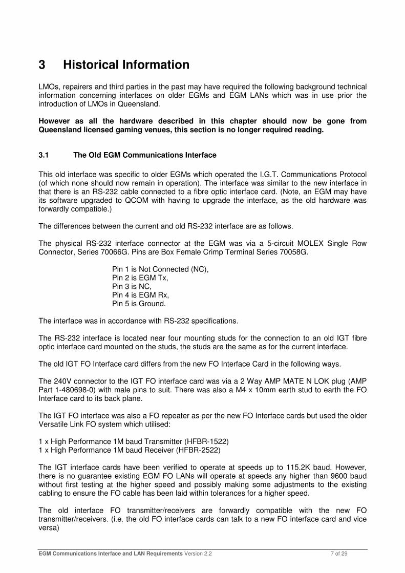
8.1.13 The FO interface card must be electrically safe to operate while being held by hand while powered and meet all applicable Australian standards.
8.1.14 If any part of the FO interface card casing is metal, then the case must be able to be earthed.
Pass �
8.1.15 The case must be labelled with the following information:-
• Manufacturer name and model/part no.
• All ports and connectors must be labelled according to their function. (FO ports must have the text “Tx”, “Rx” as their respective port’s label)
• Fuse type and rating.
• That the device is 240VAC (refer section 8.4.4)
• A laser warning, refer section 8.5.4
Pass �
8.1.16 The FO interface card must be designed with consideration to AS3260.
Pass �
8.1.17 All I.Cs on the FO interface card must have appropriate decoupling capacitors.
Pass �
8.1.18 The ICs on the FO interface card must operate from a regulated power supply. The IC voltages must be regulated with the voltage tolerances of its ICs for the specified operating range of the device (see 8.4.5).
Pass � Note. Some forms of power regulation circuits may not be suitable for use in the FO interface card as the FO Interface uses very little power. Specifically, power regulation circuits which have a minimum current requirement must not be used (e.g. some switch mode power supply circuits)
8.2 Dimensions and Mounting
8.2.1 The EGM FO interface card must occupy a space with dimensions not exceeding:
Length: 155.0 mm
Width: 86.0 mm Height: 60.0 mm*
(* note the old IGT interface cards were only 42.0 mm height)
Pass �
8.2.2 The FO interface card must be mountable on four mounting studs as described previously (refer section 6.1.1). Note: allow room to screw the nuts on.
Pass �

EGM Communications Interface and LAN Requirements Version 2.2 17 of 29
8.2.3 Provision must be made for two fibre-optic cables and connectors to be passed through the base of the EGM (toward the back of the machine cabinet) and into the console (i.e. where the cash-box is located), in such a manner such that the general public will not have access to the cable. The hole provided must have a diameter of not less than 20mm to enable the access of plastic fibre cable terminators. It is acceptable to have this hole shared with other cables.
Pass �
8.2.4 The FO interface card must be an easily replaceable component.
Pass �
8.2.5 The FO interface card must be located within the EGM so that all required cables may be easily attached once mounted.
Pass �
8.3 The FO Interface Card RS-232 Port
This port normally connects the FO Interface Card to the EGM.
8.3.1 The FO Interface card must have at least one RS-232 port meeting the following specifications.
This port shall mate with the EGM RS-232 Interface as described previously with the following considerations:
8.3.2 The FO Interface Card RS-232 interface must be in accordance with standard EIA specifications. Eg. voltage levels, rise/fall times etc.
Refer data-sheet of driver I.C. Pass �
8.3.3 The FO Interface Card RS-232 interface must not place an undue current drain on any device connected to this interface in either the power on or off condition.
With a break-out box on the RS232 signals, look for dimming of the LEDs of the interface card signals with the EGM powered on and off
Pass �
8.3.4 The FO Interface Card RS-232 interface must have at least +/- 15kV ESD protection (Human Body Model).
Refer data-sheet of driver I.C. Pass �
8.3.5 The FO RS-232 Interface must be rated to at least 115k baud.
Refer data-sheet of driver I.C. Pass �
8.3.6 The physical interface must be via a 6 circuit, RJ-12 socket connector.
Pass �
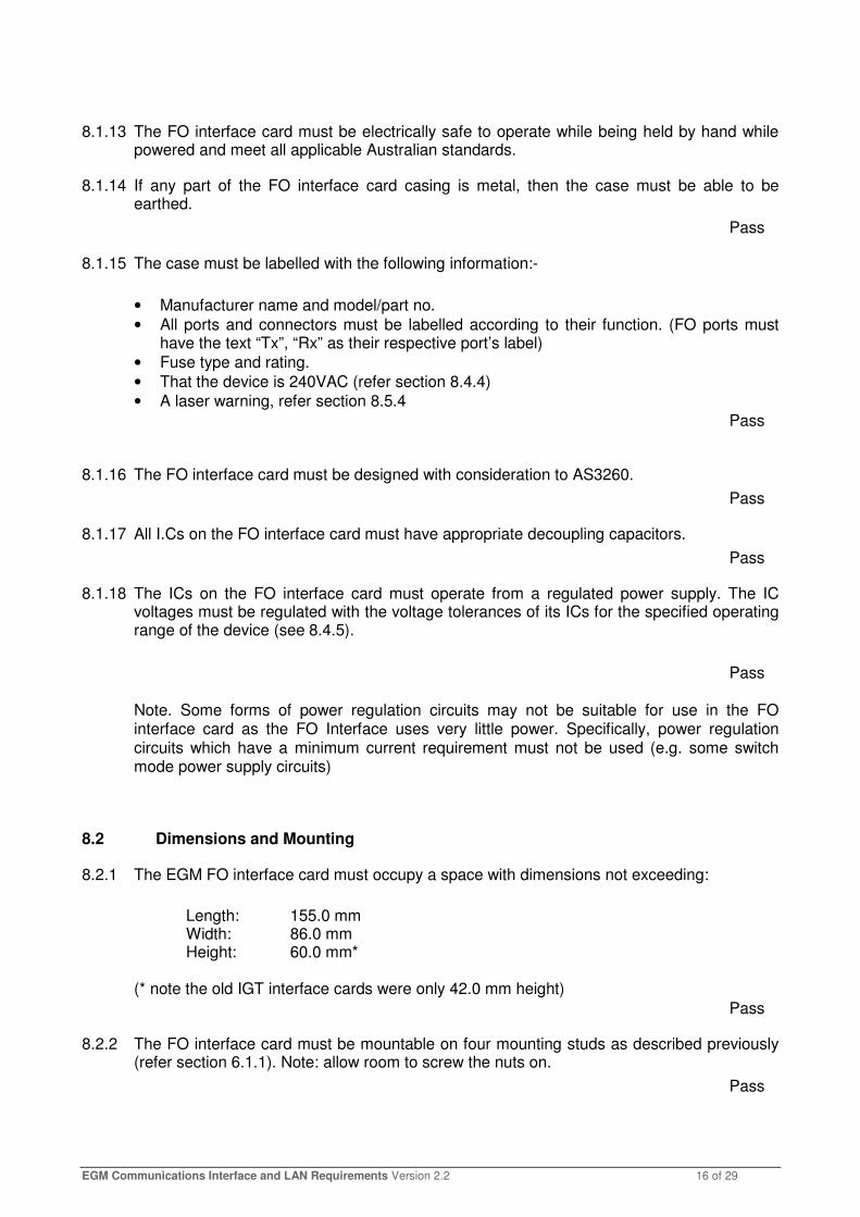
8.3.7 The FO RS-232 connector shall be in accordance with the following:
RJ-12 Pin Signal Description
1 NC No connection 2 GND Ground
EGM Communications Interface and LAN Requirements Version 2.2 18 of 29
3 Rx RS-232 Receive 4 Tx RS-232 Transmit 5 GND Ground 6 NC No connection
Pass �
8.4 FO Interface Power Connector and Fuses
8.4.1 The FO interface must connect to 240VAC power via a standard IEC C14 connector and must be earthed.
Pass �
8.4.2 The FO interface internal fuse/s must be easily replaceable.
Pass �
8.4.3 The FO interface internal fuse/s must be labelled with voltage and current rating.
Pass �
8.4.4 The FO interface card must be clearly labelled as a 240VAC device. E.g., “WARNING HIGH VOLTAGE INSIDE”
Pass �
8.4.5 Consideration must be given in the design of the FO interface card’s power supply for power surges and sags. Specifically, the FO interface card must be capable of operating with the mains supply in the range 230-240VAC +20VAC -30VAC.
Pass �
8.4.6 deleted
8.4.7 deleted
8.5 Fibre Optic Transceivers
8.5.1 The FO interface card must utilise 650nm nominal optical wavelength, “Versatile Link” compatible transceivers with a minimum data rate of 10Mbd.
Pass �
For many years the “528” series of FO transceivers were mandated by this document with legacy part numbers of:
• HFBR-1528Z (transmitter)
• HFBR-2528Z (receiver) These devices supported plastic optical fibre cable (up to 50m distance) or Hard-Clad Silica (HCS) cable (up to 500m distance). A supplier of compatible transceivers, Avago Technologies, advised OLGR (2014) of part numbers of compatible devices which they advise should now be ordered for best cost and availability reasons. The part numbers (current as of 2014) are:

EGM Communications Interface and LAN Requirements Version 2.2 19 of 29
• QFBR-GT59Z (transmitter)
• QFBR-GR59Z (receiver) In existing FOI circuit designs, changes may be required in the existing external circuitry to accommodate the new devices. Refer to the device’s data sheet for more information. There is also a new TTL based transmitter with part number QFBR-GT69Z which requires less external circuitry than the QFBR-GT59Z which could also possibly be used in new FOI designs. Note part numbers are subject to change over time. For the latest information see the link below or contact Avago Technologies: http://www.avagotech.com/pages/en/fiber_optics/general_purpose_industrial_control_data_link_650nm/
8.5.2 The interface card, FO transmitter and FO receiver circuits must be able to operate at speeds up to at least 10M baud over 50 metres of low loss plastic FO cable (@ 25 C).
8.5.3 The manufacturer recommended driver circuit must be used for the respective FO transceiver device utilised by the device.
Pass �
Please also read the relevant application notes for the given devices utilised. This contains important information regarding the circuit layout (e.g. bypass capacitor near FO Rx, Rx ground plane, Vcc range, Tx Vf, Rx Vout min/max, fan-out, etc).
8.5.4 While a warning label is not required for this class of fiber optics by ANSI, it is required under these requirements that the FO interface card must have an appropriate warning label. E.g. either use the following message or the equivalent, or the appropriate symbolic laser class symbol, or both.
“When viewed under some conditions, the optical port may expose the eye beyond the maximum permissible exposure recommended in ANSI Z136.2, 1993. Under most viewing conditions there is no eye hazard”.
Pass �
8.5.5 The FO Interface card must not be prone to latching up the FO output in the ON state
Some FO Interface card designs have in the past been found on rare occasions to be prone to latching up the FO output in the on state when exposed to a weak or intermittent FO input signal. Only a power cycle of the interface would fix the latch-up once it occurred.
One method to test for susceptibility is to disconnect all rs232 and FO cables and then by hand, manually shine an active FO signal in proximity into the FO rx port (don’t actually plug it in) until a FO output signal is observed. Then quickly remove the signal away. Repeat many times. Also try waving the FO signal across the FO rx port in close proximity. In all cases the FO output must never remain on when there is no FO input signal.

EGM Communications Interface and LAN Requirements Version 2.2 20 of 29
Perform this test with the device connected to an EGM RS232 and while disconnected from an EGM.
Pass �
Another test: With the repeat jumper on, put a fibre loop across the FO TX and FO RX. Any RS-232 tx now will cause a hard-on FO signal. Do this. Then remove the FO RX cable and the FO Tx output should immediately go inactive again.
Pass �
8.5.6 FO interface card designs containing dual FO transmitters
FO interface cards with dual FO transmitters are acceptable under these requirements. While not mandatory, they may be worth considering in new or upgraded FOI designs. Demand for these types of cards would come from third party suppliers who typically need to listen in on EGM LAN communications (refer section 10). An additional FO transmitter on FOI would greatly alleviate the need for costly (to design and approve) y-split splitters that are currently being used.

EGM Communications Interface and LAN Requirements Version 2.2 21 of 29
9 The EGM Local Area Network This section is applicable only to EGM fibre optic loops running the IGT and QCOM v1.x protocols.
9.1 The EGM FO LAN
9.1.1 The EGM local area network to be provided must be multi-point half-duplex communication fibre optic loops via approved FO Interface cards meeting the requirements in this document.
9.1.2 All FO loops must return to a central point in the gaming venue
9.1.3 This fibre optic network arrangement must be provided for and present as a part of the mandatory minimum level of monitoring whether or not their monitoring system actually uses it.
9.1.4 The gaming venue must own their EGM LAN and all directly related hardware (e.g. the FO Interfaces). This is to ensure if the gaming venue decides to switch LMOs that the cabling or hardware does not need to be removed or replaced in the process.
9.1.5 EGM FO LANs must be cabled as half-duplex multi-point loops, with preferably no more than 32 EGMs per loop and absolutely no more than 64 EGMs per loop. New monitoring systems are required to handle a minimum of 32 EGMs per loop, check the venues LMO before adding more.
Where convenient, more loops of fewer EGMs are better than one large loop, for better fault tolerance (as with this type of LAN, if one FO interface fails, then all EGMs on the same loop will also disable).

EGM Communications Interface and LAN Requirements Version 2.2 22 of 29
9.1.6 deleted
9.1.7 Each FO loop pair returning to the centralised point at the gaming venue must be individually labelled for identification.
9.1.8 Before installing a long cable run, ensure it is within the guaranteed operational limits for the given FO transmitter being used and for the selected cable type. FO Interface cards may also be used as standalone signal boosters. When used as signal boosters they should be reasonably accessible for maintenance purposes, but must never be installed in a location that is accessible to the general public.
9.1.9 For FO cable runs longer than to an adjacent machine, the cable ends (or terminating ports) must be labelled with a cable unique ID for easy identification. The labels should be of durable quality. Existing cabling (laid prior this requirement) does not have to be updated unless convenient at the discretion of the gaming venue (e.g. LAN maintenance work is undertaken).
9.2 Fibre Optic Cable types
9.2.1 There are 3 cabling options for optical fibre used by the FO interface card;
• Low Cost Standard (plastic)
• High Performance Extra Low Loss (HPELL) (plastic). Recommended.
• Hard Clad Silica (HCS) (good for very long runs)
For most cable runs, which are relatively short, e.g. from EGM to EGM, the high performance plastic cable is recommended. For longer runs, HCS cable type may be considered rather than using stand-alone fibre optic repeater boxes. Due to demand pre-terminated 3m lengths of High Performance Extra Low Loss (HPELL) cable can be purchased from some suppliers.
9.3 Deleted – Site Cabling Diagrams
9.4 Fault Finding Fibre Optic EGM Loops
For information only – there are no requirements in this section. One advantage of the type of fibre optic system used by the interface card specified in this document is that it can be effectively debugged using the naked eyeiv and without the use of any special tools. The health of an active signal at the end of a terminated cable can be ascertained by the naked eye by comparison. The quality of a terminated cable can also be ascertained by inspecting the cable end using a good magnifying glass (don’t do this when cable is active). (This is rarely necessary when pre-made terminated cable lengths are used.)
iv Refer section 8.5.4. Avoid looking directly into a FO transmitter port or active cable with remaining good eye. Instead
always observe signal strength quality indirectly e.g. by shining it onto a surface.

EGM Communications Interface and LAN Requirements Version 2.2 23 of 29
However, a common problem which occurs is when a cable is disconnected by pulling on the cable instead of the terminator; the fibre optic cable will recede down inside the terminating connector so it is no longer flush with the very end of the connector. This degrades signal quality significantly. Disconnecting a fibre optic cable by pulling on the cable should be avoided.
9.4.1 Broken Loops.
Broken loops are easy to debug, it is an all or nothing situation and simply a matter of finding where the signal stops.
9.4.2 Weak Loops.
These are harder to debug. It is possible to have a weak area in the middle of a loop, where EGMs on either side of the weak point are talking normally. This is because the FO receivers are actually an I.C that can restore a dirty signal. Weak loops have trouble with sending long messages as opposed to shorter ones. Weak loops can also be temperature dependent, heat will make a problem worse. One approach to repair a weak loop is to perform an inspection of the overall health of the signal at each receiver. When all receivers have been inspected, go back and start at the signal which looked the weakest (the dimmest) and improve its quality, then work backwards to the next dimmest until the problem is fixed by some margin. Another good indicator of where the problem lies is around the point where it is obvious EGMs are having trouble communicating via their on-screen messages. (Refer to the QCOM v1.x protocol for a description of Communications Disabling Conditions and codes.) If this doesn’t work then it may be an intermittent problem, see below.
9.4.3 Intermittent problems
Not necessarily a cabling problem but a faulty interface card, EGM RS-232 port or cable or EGM software. This is tricky to debug because the culprit may disrupt the communications of another EGM making it look like the problem. The technique of by-passing interface cards to isolate the problem works well. Selectively unplugging EGMs from the loop also works well. One thing to check is to unplug the FO loop from the Site Controller and confirm there is no data being received as should be the case. If there is any data then that will be the problem and should now be easy to find by working backwards.

EGM Communications Interface and LAN Requirements Version 2.2 24 of 29
10 Third Party EGM LAN Access This section applies to the Queensland Clubs and Hotel market only. Suppliers of third party systems such as player loyalty systems, EGM performance/management systems and jackpot systems often need to listen to information transmitted over the EGM loops running the OLGR EGM Communication Protocols in order to operate (e.g. in order to obtain EGM turnover). This section lists relevant requirements for this purpose. Note that the EGM fibre optic LAN is regulated gaming equipment under the Act. Any equipment directly (including cabling) used to tap-into or split EGM or EGM LAN communications must be approved by the OLGR in order to maintain EGM LAN integrity.
10.1 General Requirements for Methods of Tapping EGM Communications
Under QCOM v1.x, only a LMO monitoring system may transmit unsolicited data onto an EGM FO LAN, or disrupt FO loop/EGM communications. As a failsafe, third party equipment must have no physical ability or wired connection to be able to transmit data onto an EGM loop or to an EGM, or to disrupt EGM/ Site Controller communications in any way. Be advised that if any approved third party tap in equipment is subsequently found by the OLGR to cause any problems or degradation of the existing EGM LAN in a venue, then it will be immediately removed / disabled without notice by the OLGR. Approval for the third party equipment may also be withdrawn. Note the OLGR reserves the right to change the communications protocols at any time. Notice of any pending changes will be posted on the OLGR web pages in the ‘publications’ section – technical. All tap-ins must be neat and electrically sound. Note also the historical section in this document, which details differing hardware in the field will also have to be taken into account to cater for the different type of hardware which still exists in the field. There are a number of possible permissible methods to tap into the EGM FO LAN. Requirements for some of the primary methods are listed below: 1. Add a stand alone FO interface card at the end of a loop and tap into its RS-232 port. This is the preferred method as it results in the best electrical isolation. It also uses the least amount of hardware per EGM (low cost) and avoids the need to design and custom hardware as existing FO interface cards may be utilised. 2. Tap-in (e.g. via a y-split circuit) at each EGM via the EGM’s RS232 cable. This option is more risky and difficult to implement as EGM RS232 voltage levels are known to be spread across the entire permissible RS232 voltage range. If any party desires to tap in at each EGM’s RS232 signal with a Y-split arrangement then the device must comply with the following requirements:

EGM Communications Interface and LAN Requirements Version 2.2 25 of 29
• The tap-in must draw as little current from the existing RS-232 signal as possible to avoid signal degradation.
• The EGM RS-232 signal may only be passively split once per EGM.
• If the third party brings an electrical wire out of the EGM, then the RS-232 tap-in must also be via a high impedance optically isolated tap in. E.g a 10K input resistor coupled with a 1N914 diode with a 1N138 opto-coupler (this is not a circuit design recommendationv).
• A neat RS-232 Y-split cable must be used.
• If power is required from within the EGM then a 240VAC IEC C13 Y-spilt cable must be used. Active or powered Y-split circuits may be considered provided they do not degrade RS232 signal quality in any way, but rather it is expected that they preserve or even restore EGM RS232 signal quality. Active Y-splits circuits must have both signal and power isolation. If loss of power to an active Y-split circuit also disrupts an EGM’s ability to communicate, then this must affect only a single EGM and the OLGR must also be convinced that the circuit is highly reliable and must be adequately labelled, see below. Y-split devices must be labelled with:
• Manufacturer and part number
• Port labels. E.g. “To EGM”, “To FOI”, etc
• The words “QCOM RS232 Active Y-Split” or the equivalent. (Omit “Active” or equivalent word used if the device is a passive Y-split device)
3. Replace the FO Interface cards with a new card with extra ports.
• This is quite acceptable so long the interface card is approved and meets the requirements in this document.
NB, the owner of the EGM must always own the FO interface card placed in it. Refer section 9.1.4.
v Designing an opto-coupled tap-in suitable for all makes of EGMs is more difficult than this as EGM RS 232 voltage
levels are known to be spread across the permissible RS232 voltage range.

EGM Communications Interface and LAN Requirements Version 2.2 26 of 29
Appendix A Example pictures of various model of FO Interface cards. (Note cards shown were approved under older versions of this requirements document and may not meet current requirements in some minor respects (e.g. labels).)

EGM Communications Interface and LAN Requirements Version 2.2 27 of 29

EGM Communications Interface and LAN Requirements Version 2.2 28 of 29
Revision History
Version Changes QIR Who Release
Date Incept Date
1.0 Initial Release RLL 22 April,
1997
1.1
Changes were extensive, they are summarised below: Added Chapter on existing IGT interface and LANs. Due to popular request, added requirements in order to make the new interface an interchangeable (between different EGM manufacturers) component. Changed interface card FO transmitter from HFBR-1522 to 1528 to correctly allow the use of HCS FO cable. (The HBFR-0508 series is the same price as the HFBR-0502 series, however there appears to be a much greater lead time in ordering). The FO interface card DC power input must now be rated 9-12VDC instead of 9V only.
RLL 20 June,
1997
1.4
Changed EGM electrical interface back to RS-232 for backward compatibility with existing EGMs Other changes are minor, refer red-line and strike-out.
RLL 11 Nov 1997
2.0
Converted to word. General review. Added check points. Relaxed maximum EGMs per loop some (9.1.5). Added an additional FO interface card mounting requirement (6.1.5) Laser warning message now mandatory (8.5.4) Increased space around FO interface card (6.1.3) Venues must own their LAN (9.1.4)
RLL 8 Aug 2001
2.1
Updated to DEEDI report template QOGR->OLGR
RLL 20/08/2010 NA

EGM Communications Interface and LAN Requirements Version 2.2 29 of 29
Version Changes QIR Who Release
Date Incept Date
2.2 Draft
See below RLL 16-JUN-14 na
Changes:
• Updated list of compatible FO transceivers inc part no. and supplier details.
• Updated to current DJAG- OLGR document template.
• General review (it has been > 10 years!)
• Enhanced IF 240V power switch labelling and prominence requirements
• Added check regarding FO interface latch-up susceptibility.
• Added warning regarding the use of switched mode power supplies
• Added a recommendation for FOI’s have additional FO Tx ports (8.5.6)
• Clarified document scope. i.e. QCOM v1.x EGMs only
• Added consideration for RS232 Active Y-split circuits (10)
• RS232 / FOI cable type / colour and wire colours requirements deleted.
• LAN Cabling diagram requirements deleted (section 9.3)
• Added requirement 9.1.9 (FOI cabling UID for long runs) Deleted requirement numbers are still shown in this draft for reference purposes only.
2.2 See Below RLL 17-Nov-
2014 1 year
Changes from draft to final:
• Section 8.1.15 FO ports must have the text “Tx”, “Rx” on their respective port’s label
• Added another latch-on test. See 8.5.5
• Reinstated requirement 5.1.3 somewhat as the cable is actually a part of the strain relief at the RJ-12 connector. (Don’t care about colour)
• Re-instated section 9.1.3