Embed Size (px)
Citation preview

Revised on December 11th, 2014 Polakium Engineering - 0
PX4 Development
Kit for Simulink

Revised on December 11th, 2014 Polakium Engineering - 1
I. Installation and Setup:
1. Download and install ‘px4_toolchain_installer_v13_win.exe’ to ‘C:\px4\’.
2. Extract the contents of ‘px4_simulink.zip’ to ‘C:\px4\’.
3. Launch PX4 Eclipse and select ‘File > New > Makefile Project with Existing Code’,
browse to ‘C:\px4\Firmware\’ and choose “Cross GCC”.
4. Create targets ‘archives’, ‘all’, ‘distclean’, ‘clean’ and ‘upload px4fmu-v1_default’
(PX4FMU) or ‘upload px4fmu-v2_default’ (Pixhawk).
5. Launch Matlab and set the workspace to ‘C:\px4\Firmware\src\modules\simulink_app\’.
6. The configuration parameters for ‘simulink_app.slx’ have been preconfigured to utilize
the embedded coder for the PX4. The commented blocks of the model are included as an
example and may be removed. The red uncommented blocks must remain unaltered.
Placing a ‘from’ tag will acquire data from the input port paired with the same tag name.
Placing a ‘goto’ tag will send data to the output port paired with the same tag name.
* Requires additional hardware.
Function Tag Name Description Units
Radio Inputs ch1 ~ ch8 PWM radio control input signals µs
Gyroscope gyro_[x, y, z] Raw gyroscope measurements rad/s
Accelerometer acc_[x, y, z] Raw accelerometer measurements m/s2
Magnetometer mag_[x, y, z] Field strength from magnetometer ga
Pressure Altitude baro_alt Barometric pressure altitude m
Visible Satellites * gps_sat Number of visible GPS satellites
GPS Position * gps_lat, gps_lon NED GPS latitude and longitude deg
GPS Altitude * gps_alt NED GPS altitude m
GPS Velocity * gps_vel_[n, e, d] NED GPS velocity m/s
Ultrasonic Distance * sonar_dist Ultrasonic range finder m
Optical Flow * flow_x, flow_y Optical flow velocity m/s
Angular Rate rate_[roll, pitch, yaw] Angular rates rad/s
Attitude att_[roll, pitch, yaw] Attitude angles rad
Quaternion q0, q1, q2, q3 Attitude quaternion
System Runtime runtime System runtime µs
PWM Outputs pwm1 ~ pwm8 PWM output signals µs
Arm Trigger pwm_arm arm signal: true = arm; false = disarm bool
Standard LED led_{color} LED switch: true = on; false = off bool
RGB LED rgb_{color} LED intensity: 0 = min; 255 = max uint8
Debug debug1 ~ debug8 Terminal debug outputs

Revised on December 11th, 2014 Polakium Engineering - 2
7. Select “Build Model” within Simulink, and wait for successful completion of code
generation for simulink_app.
8. Confirm that the folder ‘simulink_app_ert_rtw’ has been created in the directory
‘C:\px4\Firmware\src\modules\simulink_app\’. DO NOT rename or move this directory.
9. Launch PX4 Eclipse and build the firmware by selecting the previously added targets
‘distclean’ followed by ‘archives’ and then ‘all’. Wait for each process to complete
before proceeding to the next by observing the console tab for successful completion.
10. Upload the firmware by selecting the target ‘upload px4fmu-v**_default’. DO NOT
connect the USB cable until the console window of Eclipse reads “Loaded firmware for
**, waiting for the bootloader...”.
11. Download and install ‘qgroundcontrol-installer-win32-pixhawk.exe’.
12. Erase all data from the memory card and return it to the flight controller.
13. Launch QGroundControl and connect the flight controller at a baud rate of ‘57600’.
Select the configuration tab and choose sensor calibration. Calibrate all sensors.
14. Disconnect and close QGroundControl. Remove the memory card and place the folder
‘etc’ containing ‘rc.txt’ from ‘C:\px4\Firmware\’ onto the root of the memory card. Edit
‘rc.txt’ to allow for use with the PX4FMU, PX4IO, PX4FLOW or a GPS module.
15. Return the memory card. Now the PX4 is configured to automatically execute all startup
drivers and applications associated with the Simulink application on boot.
II. Updating the Simulink Code:
1. Launch Matlab and set the workspace to ‘C:\px4\Firmware\src\modules\simulink_app\’.
2. After applying changes to ‘simulink_app.slx’, select ‘Build Model’ within Simulink, and
wait for “Successful completion of code generation for model: simulink_app” to display
in the command window.
3. Launch PX4 Eclipse and build the firmware by selecting the target ‘all’. There is no
longer any need to use the targets ‘distclean’ or ‘archives’ unless the source code has
been modified.
4. Upload the firmware by selecting the target ‘upload px4fmu-v**_default’. DO NOT
connect the USB cable until the console window of Eclipse reads “Loaded firmware for
**, waiting for the bootloader...”.
Revised on December 11th, 2014 Polakium Engineering - 3
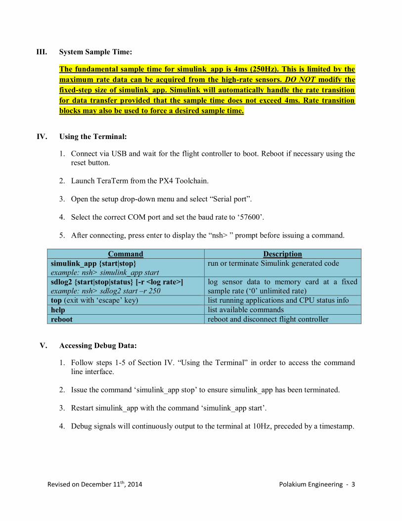
III. System Sample Time:
The fundamental sample time for simulink_app is 4ms (250Hz). This is limited by the
maximum rate data can be acquired from the high-rate sensors. DO NOT modify the
fixed-step size of simulink_app. Simulink will automatically handle the rate transition
for data transfer provided that the sample time does not exceed 4ms. Rate transition
blocks may also be used to force a desired sample time.
IV. Using the Terminal:
1. Connect via USB and wait for the flight controller to boot. Reboot if necessary using the
reset button.
2. Launch TeraTerm from the PX4 Toolchain.
3. Open the setup drop-down menu and select “Serial port”.
4. Select the correct COM port and set the baud rate to ‘57600’.
5. After connecting, press enter to display the “nsh> ” prompt before issuing a command.
Command Description
simulink_app {start|stop}
example: nsh> simulink_app start
run or terminate Simulink generated code
sdlog2 {start|stop|status} [-r <log rate>]
example: nsh> sdlog2 start –r 250
log sensor data to memory card at a fixed
sample rate (‘0’ unlimited rate)
top (exit with ‘escape’ key) list running applications and CPU status info
help list available commands
reboot reboot and disconnect flight controller
V. Accessing Debug Data:
1. Follow steps 1-5 of Section IV. “Using the Terminal” in order to access the command
line interface.
2. Issue the command ‘simulink_app stop’ to ensure simulink_app has been terminated.
3. Restart simulink_app with the command ‘simulink_app start’.
4. Debug signals will continuously output to the terminal at 10Hz, preceded by a timestamp.

Revised on December 11th, 2014 Polakium Engineering - 4
VI. Recalibrating the Sensors:
1. Follow steps 13-16 of Section I. “Installation and Setup”.
VII. Modeling and Simulation:
1. Locate the directory ‘C:\px4\multi_sim\’ and ensure that the files ‘model.stl’,
‘multi_model.slx’, ‘multi_sim.fig’ and ‘multi_sim.m’ are all located in the Matlab
workspace.
2. Open ‘multi_model.slx’ to modify the simulation for a particular vehicle.
3. Replace ‘model.stl’ with any binary .stl file, units in meters, to render a representative
model of the vehicle to the user interface.
4. Run ‘multi_sim.m’ to open the graphical user interface and begin the simulation.
Revised on December 11th, 2014 Polakium Engineering - 5
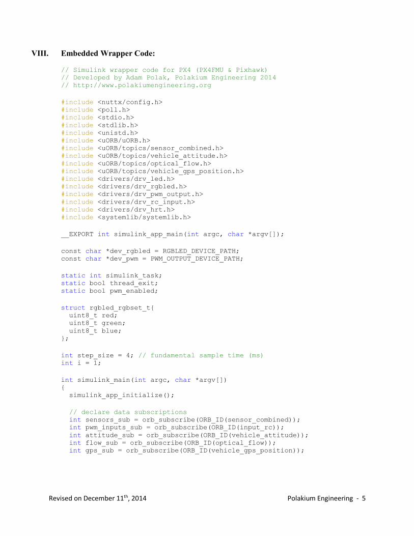
VIII. Embedded Wrapper Code:
// Simulink wrapper code for PX4 (PX4FMU & Pixhawk) // Developed by Adam Polak, Polakium Engineering 2014 // http://www.polakiumengineering.org
#include <nuttx/config.h> #include <poll.h> #include <stdio.h> #include <stdlib.h> #include <unistd.h> #include <uORB/uORB.h> #include <uORB/topics/sensor_combined.h> #include <uORB/topics/vehicle_attitude.h> #include <uORB/topics/optical_flow.h> #include <uORB/topics/vehicle_gps_position.h> #include <drivers/drv_led.h> #include <drivers/drv_rgbled.h> #include <drivers/drv_pwm_output.h> #include <drivers/drv_rc_input.h> #include <drivers/drv_hrt.h> #include <systemlib/systemlib.h>
__EXPORT int simulink_app_main(int argc, char *argv[]);
const char *dev_rgbled = RGBLED_DEVICE_PATH; const char *dev_pwm = PWM_OUTPUT_DEVICE_PATH;
static int simulink_task; static bool thread_exit; static bool pwm_enabled;
struct rgbled_rgbset_t{ uint8_t red; uint8_t green; uint8_t blue; };
int step_size = 4; // fundamental sample time (ms) int i = 1;
int simulink_main(int argc, char *argv[]) { simulink_app_initialize();
// declare data subscriptions int sensors_sub = orb_subscribe(ORB_ID(sensor_combined)); int pwm_inputs_sub = orb_subscribe(ORB_ID(input_rc)); int attitude_sub = orb_subscribe(ORB_ID(vehicle_attitude)); int flow_sub = orb_subscribe(ORB_ID(optical_flow)); int gps_sub = orb_subscribe(ORB_ID(vehicle_gps_position));

Revised on December 11th, 2014 Polakium Engineering - 6
struct sensor_combined_s sensors; struct rc_input_values pwm_inputs; struct vehicle_attitude_s attitude; struct optical_flow_s flow; struct vehicle_gps_position_s gps;
orb_set_interval(sensors_sub, step_size);
// declare output devices int rgbled = open(dev_rgbled, 0); int pwm = open(dev_pwm, 0);
// initialize outputs ioctl(rgbled, RGBLED_SET_MODE, (unsigned long)RGBLED_MODE_ON); ioctl(pwm, PWM_SERVO_SET_ARM_OK, 0); ioctl(pwm, PWM_SERVO_ARM, 0); pwm_enabled = 0;
struct pollfd fds[] = { { .fd = sensors_sub, .events = POLLIN }, };
// primary application thread while (!thread_exit) { int poll_return = poll(fds, 1, 1000); if (poll_return > 0) { if (fds[0].revents & POLLIN) { // assign sensor data orb_copy(ORB_ID(sensor_combined), sensors_sub, &sensors); orb_copy(ORB_ID(vehicle_attitude), attitude_sub, &attitude); orb_copy(ORB_ID(optical_flow), flow_sub, &flow); orb_copy(ORB_ID(vehicle_gps_position), gps_sub, &gps); orb_copy(ORB_ID(input_rc), pwm_inputs_sub, &pwm_inputs); simulink_app_U.runtime = hrt_absolute_time(); simulink_app_U.mag_x = sensors.magnetometer_ga[0]; simulink_app_U.mag_y = sensors.magnetometer_ga[1]; simulink_app_U.mag_z = sensors.magnetometer_ga[2]; simulink_app_U.acc_x = sensors.accelerometer_m_s2[0]; simulink_app_U.acc_y = sensors.accelerometer_m_s2[1]; simulink_app_U.acc_z = sensors.accelerometer_m_s2[2]; simulink_app_U.gyro_x = sensors.gyro_rad_s[0]; simulink_app_U.gyro_y = sensors.gyro_rad_s[1]; simulink_app_U.gyro_z = sensors.gyro_rad_s[2]; simulink_app_U.rate_roll = attitude.rollspeed; simulink_app_U.rate_pitch = attitude.pitchspeed; simulink_app_U.rate_yaw = attitude.yawspeed; simulink_app_U.att_roll = attitude.roll; simulink_app_U.att_pitch = attitude.pitch; simulink_app_U.att_yaw = attitude.yaw; simulink_app_U.q0 = attitude.q[0]; simulink_app_U.q1 = attitude.q[1]; simulink_app_U.q2 = attitude.q[2]; simulink_app_U.q3 = attitude.q[3]; simulink_app_U.baro_alt = sensors.baro_alt_meter; simulink_app_U.sonar_dist = flow.ground_distance_m; simulink_app_U.flow_x = flow.flow_comp_x_m;
Revised on December 11th, 2014 Polakium Engineering - 7
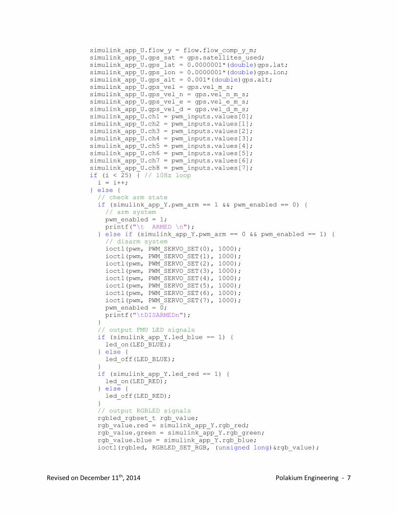
simulink_app_U.flow_y = flow.flow_comp_y_m; simulink_app_U.gps_sat = gps.satellites_used; simulink_app_U.gps_lat = 0.0000001*(double)gps.lat; simulink_app_U.gps_lon = 0.0000001*(double)gps.lon; simulink_app_U.gps_alt = 0.001*(double)gps.alt; simulink_app_U.gps_vel = gps.vel_m_s; simulink_app_U.gps_vel_n = gps.vel_n_m_s; simulink_app_U.gps_vel_e = gps.vel_e_m_s; simulink_app_U.gps_vel_d = gps.vel_d_m_s; simulink_app_U.ch1 = pwm_inputs.values[0]; simulink_app_U.ch2 = pwm_inputs.values[1]; simulink_app_U.ch3 = pwm_inputs.values[2]; simulink_app_U.ch4 = pwm_inputs.values[3]; simulink_app_U.ch5 = pwm_inputs.values[4]; simulink_app_U.ch6 = pwm_inputs.values[5]; simulink_app_U.ch7 = pwm_inputs.values[6]; simulink_app_U.ch8 = pwm_inputs.values[7]; if (i < 25) { // 10Hz loop i = i++; } else { // check arm state if (simulink_app_Y.pwm_arm == 1 && pwm_enabled == 0) { // arm system pwm_enabled = 1; printf("\t ARMED \n"); } else if (simulink_app_Y.pwm_arm == 0 && pwm_enabled == 1) { // disarm system ioctl(pwm, PWM_SERVO_SET(0), 1000); ioctl(pwm, PWM_SERVO_SET(1), 1000); ioctl(pwm, PWM_SERVO_SET(2), 1000); ioctl(pwm, PWM_SERVO_SET(3), 1000); ioctl(pwm, PWM_SERVO_SET(4), 1000); ioctl(pwm, PWM_SERVO_SET(5), 1000); ioctl(pwm, PWM_SERVO_SET(6), 1000); ioctl(pwm, PWM_SERVO_SET(7), 1000); pwm_enabled = 0; printf("\tDISARMEDn"); } // output FMU LED signals if (simulink_app_Y.led_blue == 1) { led_on(LED_BLUE); } else { led_off(LED_BLUE); } if (simulink_app_Y.led_red == 1) { led_on(LED_RED); } else { led_off(LED_RED); } // output RGBLED signals rgbled_rgbset_t rgb_value; rgb_value.red = simulink_app_Y.rgb_red; rgb_value.green = simulink_app_Y.rgb_green; rgb_value.blue = simulink_app_Y.rgb_blue; ioctl(rgbled, RGBLED_SET_RGB, (unsigned long)&rgb_value);

Revised on December 11th, 2014 Polakium Engineering - 8
// print debug data printf("%8.4f\t%8.4f\t%8.4f\t%8.4f\t%8.4f
\t%8.4f\t%8.4f\t%8.4f\t%8.4f\n", (double)(simulink_app_U.runtime/1000000), (double)simulink_app_Y.debug1, (double)simulink_app_Y.debug2, (double)simulink_app_Y.debug3, (double)simulink_app_Y.debug4, (double)simulink_app_Y.debug5, (double)simulink_app_Y.debug6, (double)simulink_app_Y.debug7, (double)simulink_app_Y.debug8); i = 1; } // output pwm signals if (pwm_enabled == 1) { ioctl(pwm, PWM_SERVO_SET(0), simulink_app_Y.pwm1); ioctl(pwm, PWM_SERVO_SET(1), simulink_app_Y.pwm2); ioctl(pwm, PWM_SERVO_SET(2), simulink_app_Y.pwm3); ioctl(pwm, PWM_SERVO_SET(3), simulink_app_Y.pwm4); ioctl(pwm, PWM_SERVO_SET(4), simulink_app_Y.pwm5); ioctl(pwm, PWM_SERVO_SET(5), simulink_app_Y.pwm6); ioctl(pwm, PWM_SERVO_SET(6), simulink_app_Y.pwm7); ioctl(pwm, PWM_SERVO_SET(7), simulink_app_Y.pwm8); } else { ioctl(pwm, PWM_SERVO_SET(0), 1000); ioctl(pwm, PWM_SERVO_SET(1), 1000); ioctl(pwm, PWM_SERVO_SET(2), 1000); ioctl(pwm, PWM_SERVO_SET(3), 1000); ioctl(pwm, PWM_SERVO_SET(4), 1000); ioctl(pwm, PWM_SERVO_SET(5), 1000); ioctl(pwm, PWM_SERVO_SET(6), 1000); ioctl(pwm, PWM_SERVO_SET(7), 1000); } // execute simulink code simulink_app_step(); } } } // disable pwm outputs ioctl(pwm, PWM_SERVO_SET(0), 1000); ioctl(pwm, PWM_SERVO_SET(1), 1000); ioctl(pwm, PWM_SERVO_SET(2), 1000); ioctl(pwm, PWM_SERVO_SET(3), 1000); ioctl(pwm, PWM_SERVO_SET(4), 1000); ioctl(pwm, PWM_SERVO_SET(5), 1000); ioctl(pwm, PWM_SERVO_SET(6), 1000); ioctl(pwm, PWM_SERVO_SET(7), 1000); ioctl(pwm, PWM_SERVO_DISARM, 0); // disable LEDs led_off(LED_BLUE); led_off(LED_RED); ioctl(rgbled, RGBLED_SET_MODE, (unsigned long)RGBLED_MODE_OFF);

Revised on December 11th, 2014 Polakium Engineering - 9
// close sensor subscriptions close(sensors_sub); close(attitude_sub); close(flow_sub); close(pwm_inputs_sub); close(gps_sub); // terminate application thread exit(0); }
int simulink_app_main(int argc, char *argv[]) { // start primary application thread if (!strcmp(argv[1], "start")) { thread_exit = false; simulink_task = task_spawn_cmd("simulink_app", SCHED_DEFAULT, SCHED_PRIORITY_MAX - 15, 10240, simulink_main, NULL); exit(0); } // terminate primary application thread if (!strcmp(argv[1], "stop")) { thread_exit = true; exit(0); }
exit(1); }