Embed Size (px)
Citation preview
. - - _ . - _ . - - _ _ _ _ _ _ _ _ _ _ _ _ _ _ _ . _ _ _ _ _ _ _ _ _ _ _ _ _ _ _ _ _ . . . _ _ - _ _ . . . _ . . . . . _ _ _ _ _ _ _ _ _ _ _ _ _ - - _ .-
t-- . . . . - _
tyrT. I'
i
PWR SAFETY AND RELIEF VALVE
Adequacy Report
For |
Georgia Power Company
Alvin W. Vogtle Unit 1 and Unit 2;
) Original Issue
l
| May 31, 1985.i
I.I
1
. ..
i:
!
.
|s
,
! ;
i
i! ,
!'
i
)! Westinghouse Electric Company1
iPlant Engineering Division
i Box 355:
j Pittsburgh, Pennsylvania 152301
1
i
il.
| :-
;
!!u%B8nBi83$g4E
. .____ _ _ - - _ _ _ _ . - _ . - -. - - - _ -- _ _ . . - _ .-

- .- __ _ _ - . ._ - _ , .- _. . _ _ _ .
[O .. . . . .. .. |- I. , . . . _ _ . .
~
iee i
.
e
Table of Contents;g
Section g
1.0 Introduction 1
2.0 Valve and Piping Parameters 2
,
3.0 Valve Inlet Fluid Conditions 9
4.0 Comparison of EPRI Test Data 13
with Plant-Specific Requirements,
4.1 Relief Valve Testing 13
4.2 Safety Valve Testing 13
4.2.1 Crosby 6M6 Safety Valve Tests 14
4.2.2 Discussion of Observed Safety 15
Valve Performance4.2.2.1 Loop Seal Opening Response 16
:
- 4.2.2.2 Inlet Piping Pressure Oscillations 16
4.2.2.3 Valve Chatter on Steam 16 ;
t
5.0 Conclusions 22
Appendix I
References
.'
.
1
P
|,
-
. . _ . ._ ._ _ . -- . . .. . -.

... . . - . -. ._ . _ _ _ . -, - . , . - .. .
. ic x .._ . . . . .
. . - . .-.. . ..... .: ... ... . ._.._ _ . .... ,, . , ,
.
.
.
Revision Pane
Revision Description Author
0 Original Issue R. M. Grayson
iI
I
.
.
J
!l.
,
i
i
4
i
!
.
t
i *
!.
*f
.
I
\
11|
_ _ _ . _ _ .
M510:10/053185- - - . . _ _ . - _ . . - _ . _ . _ _ _ _ . _ _ _. _ _ _ _. ,
-- ._ - _ _ _ _ _ _ . _ - _ - . . - - - - - - . _ - - _ _ _ __
' *
u ,. . . .. . :..-
..
'
.
~
1.0 INTRODUCTION
I
In accordance with the initial recommendation of NURE6 0578, Section 2.1.2 aslater clarified by NORE6 0737, item 11.0.1 and revised September 29, 1981,each Pressurizer Water Reactor (PWR) Utility was to submit informationrelative to the pressuriter safety and relief valves in use at their plant.'
Specifically, this submittal should include an evaluation supported by test ,i
results which demonstrate the capability of the relief and safety valves tooperate under expected operating and accident conditions.
The primary objective of the Electric Power Research Institute (EPRI) testi
program was to provide fuli scale test data confirming the functionability ofthe primary system power operated relief valves and safety valves for expected
<
operating and accident conditions. The second objective of the program was
to obtain suf ficient piping thermal hydraulic load data to permit confirmation ,
of models which may be utilized for plant specific analysis of safety and!
relief valve discharge piping systems. Relief valvc tests were completed in'
August 1981 and safety valve tests were completed in January 1982. Reports'have been prepared by EPRI which document the results of the test program.
' Additional reports were written to provide necessary justification for test
j valve selection and valve inlet fluid test conditions. These reports were !
transmitted to the USNRC by David Hoffman of the Consumers Power Company on |behalf of the participating PWR Utilities and are referenced herein. |
,
I
< i
This report provices the final evaluation of these and other submittals and
|reports prepared during the review of the test data as they apply to the
j valves used at Alvin W. Vogtle Units 1 and Unit 2.
!
!
,
e
:.
I
i
| M510:10/053185 1
__ - _-- - - _ _ _ _ _ _ _ _ _ _ . . - -__ _ - - _ -. . _ _ _ - - . - - _ _ . _ _ _ _ _ _ - - . . _ _ - _ _ . _ _ _
.. _ . _ _ ___ _ _ _ __ _ _ _ . . _ _ _ _ _ . - _ _ _ _ . _ _ . _ __ _ _ ._ _._*
_
** . -.. .. .. : ::.; . . -
~
.
2.0 VALVE AND PIPING PARAMETERS'
i
!
Table 2-1 provides a list of pertinent valve and piping parameters for the
| Alvin W. Vogtle Units Safety and Power-0perated Relief Valves. The safety.
valve and Power Operated Relief Valve designs installed at Alvin W. Vogtle . f
| were tested by EPAI. Information concerning the valves tested versus valvesI
! installed at Alvin W. Vogtle is provided in the Valve Justification
report. The justification was developed based on evaluation perfonned by ,
the valve manufacturers and considered effects of differences in operating j
| characteristics, materials, orifice sizes and manufacturing processes on valve
i operability.
! Typical inlet piping configurations for Alvin W. Vogtle Unit 1 and Unit 2 arei provided in Figures 2-1 and 2.2 ,
i
Tables 2-2 and 2-3 compare the Alvin W. Vogtle inlet loop seal pipingI
I configuration with that of the EPRI test piping arrangement for the crosby 6M6Safety Valve and compares the actual plant-specific pressure drop with thetest pressure drop for the test valve arrangement.
.
: 1
As can be seen by these comparisons, the EPRI test piping arrangement envelops |4
|
|the actual piping arrangement for the Alvin W. Vogtle units in that the piping
| arrangements are similar and the Vogtle Plant pressure drops are less than !
!i
those for the EPRI test valve arrangement.j
i
!
!.
i
1
!
I
1
|.-
; -i
!!
!:
|
)06510:10/053105 2
i
- - _ - - __ - _ _ _ _ . _ . _ - _ _ _ . _ . _ _ _ _ _ _ _ _ _ _. _ _ . _ _.__ -- _ _ _ _ .

;. _ _
,,
, , .. . . . . . . . . .. .. .
.
-
.
-
TABLE 2-1
VALVE AND PIPING INFORMATION!
i 1. SAFETY VALVE INFORMATION
Number of valves 3
Manufacturer Crosby Valve and Gage iType Self ActuatedSize 6M6
Steam Flow Capacity,1bs/hr 420,000;
Design Pressure, psig 2485Design Temperature. *F 650Set Pressure, psig 2405
Accumulation 3 percent of set pressure !; Blowdown. 5 percent of set pressure'
Original Valve Procurement Spec. E-678838,
! 2. RELIEF VALVE INFORMATION,
,
i
|j Number of Valves 2
Manufacturer GarrettType Pressurizer Power Relief
I Size 3x6
f Steamflow Capacity, Ibs/hr 210,000 max
; Design Pressure, psig 2500 '
Design Temperature. *F 650
; Opening Pressure, psig 2335Closing pressure, psig 2315 !
Valve Procurement Spec. G-g55245:
| ,
:
i1
.
P
k
06510:10/053185 3. . _ _ . _._ _ _ . _ - . _ . _ ____ . . _ . _ _ _ _ _ _ _ __ __.-_ . . - _ - _ _ _ _ _ - - _ _ -

.__ - _
c= . . ...... .. .
.
~
TAOLE 2-1 (Continued)o |
VALVE AND PIPING INFORMATION
3. SAFETY AND REllEF VALVE INLET PIPING INFORMATION
Design Pressure, psig 2485
Design Temperature. *F 680
Configuration of Piping 1548E34'
Pressurizer Nozzle Configuration 1548E34
3Loop Seal Volume, ft Volume .71
Loop Seal Temperature, 'F Approximately 200*F^
Steady State FlowPressure Drop See Appendix !
Acoustic Wave PressureAmplitude See Appendix I>
'
4. SAFETY AND REl1EF VALVE DISCHARGE PIPING INFORMATION
Design Pressure, psig 2500
Design Temperature. 'F 600
Configuration 1548E34
i
Pressurizer Relief TankDesign Pressure, psig 1 00
Dackpressure, Normal, psig 3
} Dackpressure. Developed, psig 500
|
-, ,
,
;
06510:10/053185 4_ _ _

1,.. . ' ' . .. . . _ _ .
'
.
*
FIG. 2-1.
,
-TYPICAL SAFETY ~ VALVE INLET PIPING
.
4
.
sm ;-
nu t.
~.
u-
g ~ n -
= y-
M u--
,#~ j, w l'
N"( / '
j,
%( \ / ! /'
<
\\ y P.. &. / /-
.
'.:," .1 ;- a
F-
er ~,, .
. .._, . .'
.-s.s ,3 ,-
g} ,.. q--
I| -!
) ) ~|g n' *
w'.s- \
,.
-r-rt d .---
~w .,e j -r __
i,
2- S
',r -
i _r .
o ,7 )*W LE '
sl y .Ow # I, ,, ~
..- -- g-- g-- q - g1 '
N. [_,'N . . ' f.'
-
~
u< s. .
% I u% \II mV'~
~ ~~
il ~| j~
s
\m- e ~.
c z o n\ ,
I 'g s,/\e. N
w % -- u.>i 1O
E
WW
h6isn
** 6 |-
ey eue ';wNE
*.
O5

.
:g ., . 7. 7. .. - .,
- ~ FIG. 2-2. TYPICAL PORV INLET PIPING
.
I. _ ..,- y.................,__"
.**"_,.*( |
_a -- _. -- .,. --
: I |e
d= h----
'N i i,
\.
k:''.... ,
# SI'['
'/ . Ud'.
7 '
,,- N
\ N\ \ -*
' f -- -- {- N''-- --
y gs -- ? - ~
#. ,
_p &( sj: ' -
.- -
,\ 1|
,,
i*
s'
gN sjW.
N '
---- p' t5.,
i SECTION J J \ .i , = K=-.. %
_-
N ~.
- REF PL A?.E FCR F; ELD #/
t -
t~~~r , a g
e'' .e I -D. 4f',
.*
1 I- I*
_ ./ i-
,i 1,-
- - -
, ,, ,
-- . . i . i i-- .. -- .6; -- __ -- __
b;8
.. e e
... I .8,'*2 .. ........ ....J SUGGESTED INSUL ATIOP.**
s% .. QUTL|hE |,
|*f.5U. ATION SUPP08 T 'mRING SUPPL:ED BY OTHERS l
.
| 28.89.
29.25 .n F
s;'.5s.4?;;= Ctv.s *
.
to.so :e.co.
REF PEV
VIEW A- A ..

-,. .- . )y,. . . . .- i
j. .
.
1'
TABLE 2-2*
.
SAFETY VALVE INLST PIPING COMPARISON
TypicalAlvin W. Vogtle 6M6 Inlet
inlet Picina Pipina*
Length of 44.8 61
straight pipe, in.
Number of 90* 2 -
elbows
Number of 180' 1 2
bends
Number of 45' 1 -
. Elbows,
71Misc. -
Loop seal water .71 1.02
volume.
* Source: Reference (7),
*.
e
_ , _ _ _ . _ _ _ _ _ . . _ ._ , _ _ , , _. - - _ .

s. .
4 ,i . . .. :. . . . . . . . ' . .., .:...
.
.
! -'
TA8LE 2-3..
COMPARISON OF TEST PRESSURE DROP WITH
PLANT SPECIFIC PRESSURE DROP
Alvin W. VogtlePlant Specific * 6M6 Test **
Pressure Dron Pressure Broo
Opening 244.1 263
Closing 142.6 181
1
Appendix I*
. ** Source: Reference (8)
.
:
:.
|
8M51Q:10/053185_ _ _ _ _ ._ ___ .-_
. _ . . _ _. . _ _ _ __ _ _ - . . _ . _ _
_
wn . . ._ _ .. . . . . . _ _ - . _ . .
.
f
- 3.0 VALVE INLET FLUID CONDITIONS
i
.lustification for inlet fluid conditions used in the EPRI Safety and Relief
Valve tests are summarized in Reference 2 and 3. These conditions weredetermined based on consideration of FSAR, extended High Pressure Injection,
and Cold Overpressurization events, where applicable.
For plants of which Westinghouse is the NSSS supplier, a methodology was usedI
such that a reference plant was selected for each grouping of plant i
considered.(3) Valve fluid conditions resulting from limiting FSAR events,
f which result in steam discharge and an Extended High Pressure Injection eventwhich may result in liquid discharge, are presented for each reference plant.
.
Use of reference plants result in fluid conditions enveloping those expectedfor Alvin W. Vogtle Unit 1 and Unit 2. |
Table 3-1 presents the results of loss of load and locked rotor analysis forFour loop plants in which Alvin W. Vogtle Unit 1 and Unit 2 were included. |
; The inlet fluid conditions expected at the safety valve and PORY inlets are f|
,
As can be seen, the Loss of Load event is considered as theidentified.i limiting overpressure transient, however, the rate of pressurization is higher
'for the Locked Rotor Transient for four loop plants.
L
'
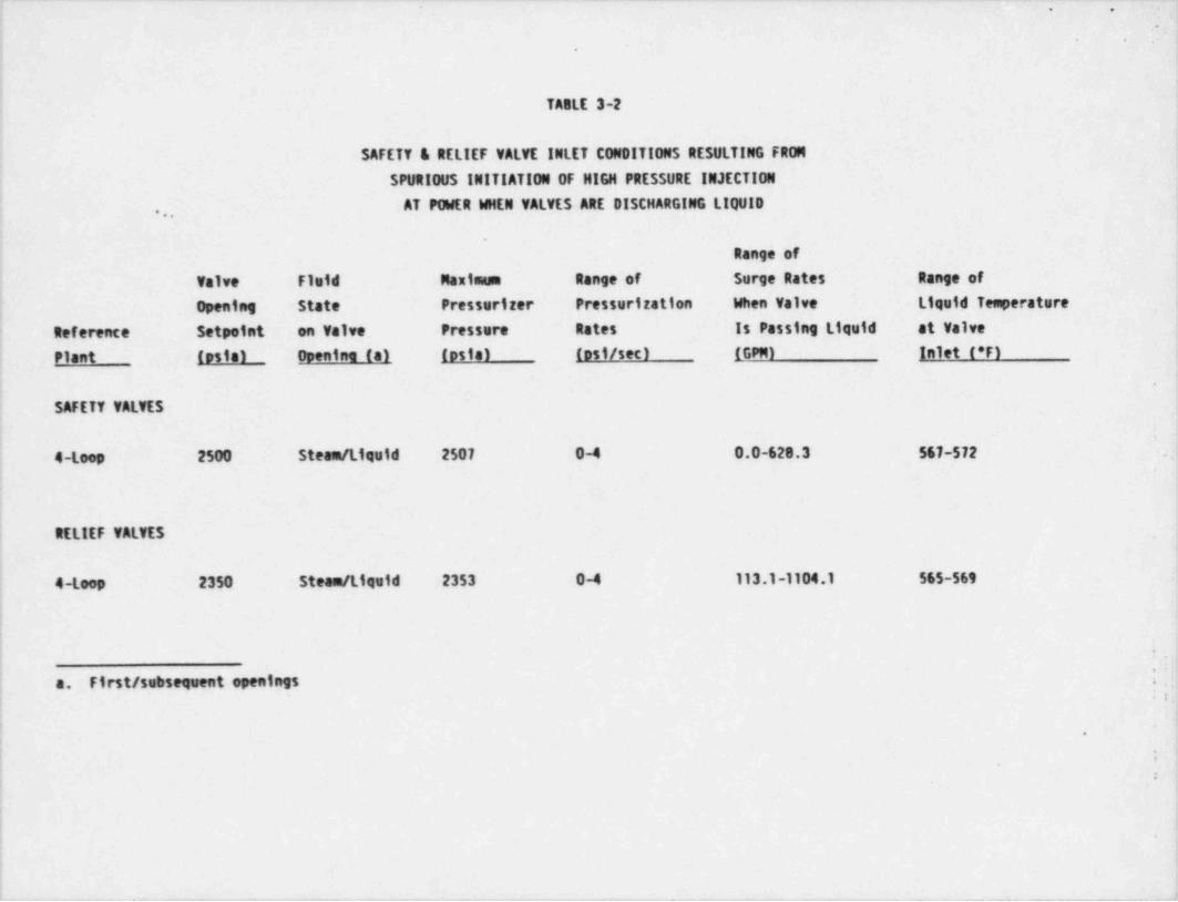
The limiting Extended High Pressure Injection event was the spuriousactivation of the safety injection system at power. A condition II event,
!this will result, at worst, in a reactor shutdown with the plant capable of |returning to operation. The analysis results for four-loop plants are
| provided in Table 3-2..
>
! !
The cold overpressure fluid inlet conditions considered for the relief valves [;'
'
are provided in Figure 3-3. These conditions represent possible water, steamand steam to water inlet conditions for the Vogtle PORV's. j
!!The only transients for PORV and Safety Valves identified for Alvin W. Vogtle4
are the FSAR, High Pressure Injection, and cold overpressure conditions.
;
| !
| ?i
06510:10/061085 9 |- .-_ _ - - - . . .- - _ . _ - - - -

, . . .. . l-. . . . _ . . . . . . . _ . . . . . '. c_ . . .
~
|*
.
TABLE 3-1.
!
VALVE INLET CONDITIONS FOR FSAR
EVENTS RESULTING IN STEAM OISCHARGE
Maximum Maximum
Valve Pressurizer Pressure Rate
Reference Opening Pressure (psia)/ (psia /sec)/Plant Pressure (osia) Limitina Event Limitina Event
Safety Valves Oniv,
i
4-Loop 2500 2555/ Loss of Load 144/ Locked Rotor.
Safety and Relief Valves
4-Loop 2350 2532/ Loss of Load 130/ Locked Rotor
.
Source: Reference (2)
:'
1
. - __ -_+n.-
_ _ _ _ _ _ . _ _
,
.
' '
.
TABLE 3-2
SAFETY & RELIEF VALVE INLET CON 0!TIONS RESULTING FRON
SPURIOUS INITIATION OF HIGH PRESSURE INJECTION
AT POWER WHEN VALVES ARE DISCHARGING LIQUID,,,
.
Range of
; Valve Fluid Maximum Range of Surge Rates Range of
Opening State Pressurizer Pressurization When Valve liquid Temperature
Reference Setpoint on Valve Pressure Rates Is Passing Liquid at Valve'
Plant testa) openine (a) (psia) (est/sec) (GPN) Inlet (*F).
SAFETY VALVES'
4-Loop 2500 Steam / Liquid 2507 0-4 0.0-628.3 567-572 .'
.
Ij RELIEF VALVES
4-Loop 2350 Steam / Liquid 2353 0-4 113.1-1104.1 565-569,
i
!
.
| a. First/ subsequent openings ' , ,j .:
i .
; '
\"
i
i!
+.---_. _ _ _ _ _ _ _ _

. . . _ - -- .- -
_, _
w ,. . . . .. _ . . . . .
.
.
TABLE 3-3.
PORY INLET CONDITIONS FOR COLD OVERPRESSURE TRANSIENTS
11:33 Steam to Water Wa.t.t.t
2350 psi 400 - 2350 psi 800 psi
650*F Sat Temp 70 - 350*F
4
1
i
.i
.
:
i*1
<
J
:--
.
|
1286510:10/053105_ _ _ . _ _ _ _ _ _ _ . _ . _ _ . _ _ _ _ _ _ . . _ _ _ _ _ . . _ _ _ _ _ _ _ _ _ , ,_,_. _ _ _ _ _ _ . . . _ _ .__
. - - . . _ - - - _ . . . . .. -- -.
$?i .
. 1
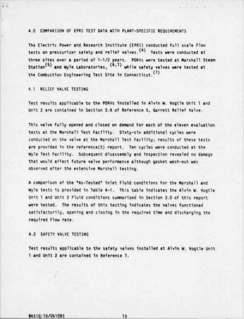
4.0 COMPARISON OF EPRI TEST DATA WITH PLANT-SPECIFIC REQUIREMENTS |
|-
The Electric Power and Research Institute (EPRI) conducted full scale flow4
tests on pressurizer safety and relief valves.I4) Tests were conducted atthree sites over a period of 1-1/2 years. PORVs were tested at Marshall Steam
| Station (5) and Wyle Laboratories, (6,7) while safety valves were tested at
the Combustion Engineering Test Site in Connecticut.
4.1 RELIEF VALVE TESTING '
j
Test results applicable to the PORVs installed in Alvin W. Vogtle Unit 1 andUnit 2 are contained in Section 3.9 of Reference 5. Garrett Relief Valve.
This valve fully opened and closed on demand for each of the eleven evaluation .
tests at the Marshall Test Facility. Sixty-six additional cycles were
| conducted on the valve at the Marshall Test Facility; results of these tests! are provided in the reference (5) report. Ten cycles were conducted at the
Wyle Test Facility. Subsequent disassembly and inspection revealed no damage! that wou'1d affect future valve performance although gasket wash-out was.
,
observed af ter the extensive Marshall testing.3
i'
A comparison of the 'As-Tested" inlet fluid conditions for the Marshall and
| Wyle tests is provided in Table 4-1. This table indicates the Alvin W. VogtleUnit 1 and Unit 2 fluid conditions sunnarized in Section 3.0 of this report
'
were tested. The results of this testing indicates the valves functioned
; satisfactorily, opening and closing in the required time and discharging therequired flow rate.
4.2 SAFETY VALVE TESTING
Test results applicable to the safety valves installed at Alvin W. Vogtle Unit,
1 and Unit 2 are contained in Reference 7.i
1.
i :!
Il
.
t
8651Q:10/061085 13_ _ _ _ . ______
__ _ __ _.. . ._ __ _ _ _ . . _ - . _ _ _ - _
mx. - . ... . ... a ... .. ._ . _ . . . . . . _ . _ . . . .
'
.
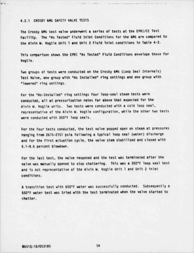
. 4.2.1 CROSBY 6M6 SAFETY VALVE TESTS
|
The Crosby 6M6 test valve underwent a series of tests at the EPRI/CE Test )
Facility. The "As Tested * Fluid Inlet Conditions for the 6M6 are compared to |
the Alvin W. Vogtle Unit 1 and Unit 2 Fluid inlet conditions in Table 4-3.,
This cegarison shows the EPRI 'As Tested * Fluid Conditions envelope those forVogtle.
Two groups of tests wre conducted on the Crosby 6M6 (Loop Seal Internals)
! Test Valve, one group with 'As Installed" ring settings and one group with! 'lowred" ring settings.
For the "As-Installed" ring settings four loop-seal steam tests wereconducted, all at pressurization rates far above that expected for theAlvin W. Vogtle units. Two tests were conducted with a cold loop seal,i
1 representative of the Alvin W. Vogtle configuration, while the other two testswere conducted with 350*F loop seals.
I For the four tests conducted, the test valve popped open on steam at pressures~
ranging from 2675-2757 psia following a typical loop seal (water) discharge!
and for the first actuation cycle, the valve stem stabilized and closed withi
| 5.1-g.6 percent blowdown.:
For the last test, the valve reopened and the test was terminated af ter thevalve was manually opened to stop chattering. This was a 350*F loop seal testand is not representative of the Alvin W. Vogtle Unit 1 and Unit 2 inlet
! conditions.
A transition test with 650*F water was successfully conducted. Subsequently a
550*F water test was tried with the test terminated when the valve started to* chatter.
:
; .-|
86510:10/053185 14
_ _ _ -_ . - . - . - _ - . _ _ _ _ _ - _ -_ - _ - _ _ _ - - _ _ _ - - - - . . - . -

_. . _ . _ _ _ _ _ _ _ _ __ _ _ _ - - _ _ _ _ _ ._ ___ _ _ _ _ _ _ _ _ _ _ - _ _ _ _
_ . _ . _ _ ~ _ . . _ . . . .;" - --- -. ..
!
I-
f' Seven additional loop seal tests were conducted with * lowered' ring settings
!' as well as two additional transition tests. The results of those tests are! detailed in Reference 7.
Five cold loop seal steam tests were performed at ramp rates from 3-375psi /sec. The valve exhibited typical loop seal openings with the full opening
,
pressures varying from 2580-2732 psia depending on ramp rate. The valveclosed in a range of 1.4 to 0.2 percent blowdown.-
'!
Two hot loop seal tests were conducted with full opening pressures of2655-2692 psia after the typical loop seal opening, and closed with 8.2-g.0
i percent blowdown. In the second test the valve reopened and chattered. Againthis was a 350*F loop seal test at a high ramp rate and is not considered
j representative of the Alvin W. Vogtle Unit 1 and Unit 2 inlet conditions.i4 <
4.2.2 DISCUS $10N OF OBSERVED SAFETY val.VE PERFORMANCE
|! In addressing observed valve performance, one must differentiate between the
valves and fluid conditions tested and the actual valves and actual fluid.
conditions for the specific plant. The EPRI inlet piping arrangement, flowand acoustic pressure drops, and inlet fluid conditions bound the same
;
| plant-specific parameters for the Alvin W. Vogtle units. Valve performancei
| observed during the EPRI tests, therefore, reflects worst case performance ascompared to results that would be observed had the testing been conducted!
using actual plant-specific piping arrangements and fluid conditions.'
A review of Table 4-3 shows the Crosby safety valve tested exhibited stable'
f operation on a loop seal piping configuration at pressurization rates of1.1-375 psi /see with initial opening pressures of 2455-2600 psi and pop
| pressures of 2455-2757 psi.1
The EPRI data also indicates that steam flow rates in excess of rated flowsf
;
are attainable. However. data also shows these flow rates are delayed some'
| period of time following the assumed valve opening point resulting in the high
j pop pressures'. ,
,
*
06510:10/053185 15__. - _ _ _ - _ _ . . - . -_ _ _ -_ - - __ - -__- _ - _ . . - _ _ _ _

_ _ _ _ _ _ _ _ _ _ _ _ . _ . _ _ _ _ _ _ . . _ _ _ . _ _ _ _ _ _ . _ _ _ _ _ _ _ _ _ _ _ _ _ __
u~ .. . .
i-;
Safety valve p rformance observed in the EPRI tests is addressed inI* Reference g for Westinghouse Plants and the results and conclusions of this
report can be extended to Alvin W. Vogtle Unit 1 and Unit 2.
!! 4.2.2.1 LOOP SEAL OPENING RESPONSE
!,
f To assess the effect on reactor coolant system pressure due to valve opening
| response on loop seal discharge, a series of overpressure transients were runwith various time delays inserted for the valve opening. Results of the:
j analysis are presented in Reference g. For the limiting Condition 11 events,
f safety valve functioning is not required if the reactor trips on high
) pressurizer pressure. If the reactor does not trip until the secondprotection grade trip, a valve opening delay time of two seconds would still
!
I provide acceptable overpressure protection. Evaluation of the limiting
| condition IV event shows all components of the reactor coolant system wouldremain within 120 percent of the system design pressure even in the event of
i no safety valve opening.1
4
4.2.2.2 INLET PIPING PRESSURE OSCILLATIONS,
i
As observed during the loop seal discharge tests, oscillations occur upstreamof a spring loaded Safety valve while water is flowing through the valve. An
) analysis of this phenomenon was conducted and the results are documented inReference g. Table 4-4 provides the maximum permissible pressure for
|. pressurizer Safety valve inlet piping sites and schedules representative ofWestinghouse plants. These pressures are shown for upset (level 0) and-
emergency (level C) conditions. Based on tests and analytical work to date,1 all acoustic pressures observed or calculated prior to and during safety valve|
discharge are below the maximum permissible pressure.iI
4.2.2.3 VALVE CHATTER ON STEAMi
Since the Eptl testing was conducted at enveloping fluid and pipingi
conditions, adjustments were made to the safety valve ring positions in order-
.i
|| !
'8
i I'
l
! 06510:10/0531s5 16- . - - - - . - . - - - _ - _ - - -.- -- - . . - . . .- _. . - .. J
.5 *
, . . . . . . . . . . . . .
.
.
. to obtain stable valve performance on steam discharge for the testarrangement. These adjustments resulted in longer blowdowns for the test-
valves. The ring positions determined during the test represent theadjustment required for a particular valve when exposed to the particular testpiping arrangement, fluid conditions, backpressure and pressurization rate.
An investigation was conducted to determine those parameters which arecritical to the onset of valve chatter under steam discharge conditions. Theresults of this study are detailed in Reference 9.
;
. ,
.
9
:.
M510:10/053185 17
- . . . . - _ - . .-.

c+. :.
.
.
TABLE 4-1-
.
COMPARISON OF PORY INLET FLUID CONDITIONS
WITH 'AS-TESTED' CONDITIONS
Steam Conditions!
P0AV Marshall Test i
iplet Fluid Wyle Test (No.1 - No.11)
Set Point 2530 2346-2415 2405-2460
Pressure (psia)
Temperature 650 669-674 (sat.)('F)
Fluid Type steam steam steam,
|
Flow Rate 210.000 (372.600-378.000) (292.000-303.000),
(1bs/hr)Water Conditions
MVInlet Fluid Wyle Test Wyle Tests
Conditions 104-GA-SS/W (Water)
i
i Set Point 2350 2460 510-2486.
; Pressure (psia)!
1 Temperature 565-569 650 106-648
(*F)
Fluid Type steam W ater steam / Water Water-
,
Flow 8 ate #/hr (33.927-33.203) 792.000 (813.600-1.681.200)'
i -
I
[
l'
|
96510:10/053185 18_ _ _ _ - - - - _ _ . _ _ _ . . . - _ - _ _ _ _- -_ - _ _ - _ _ _ _ _ _ _ _ _ _ _ -. . _ - . - _
._. _ _ _ _ . _ _ _ _ . . ._ _ . _ . _ _ .__ _ _ _ .
:ev. . . . .
'.
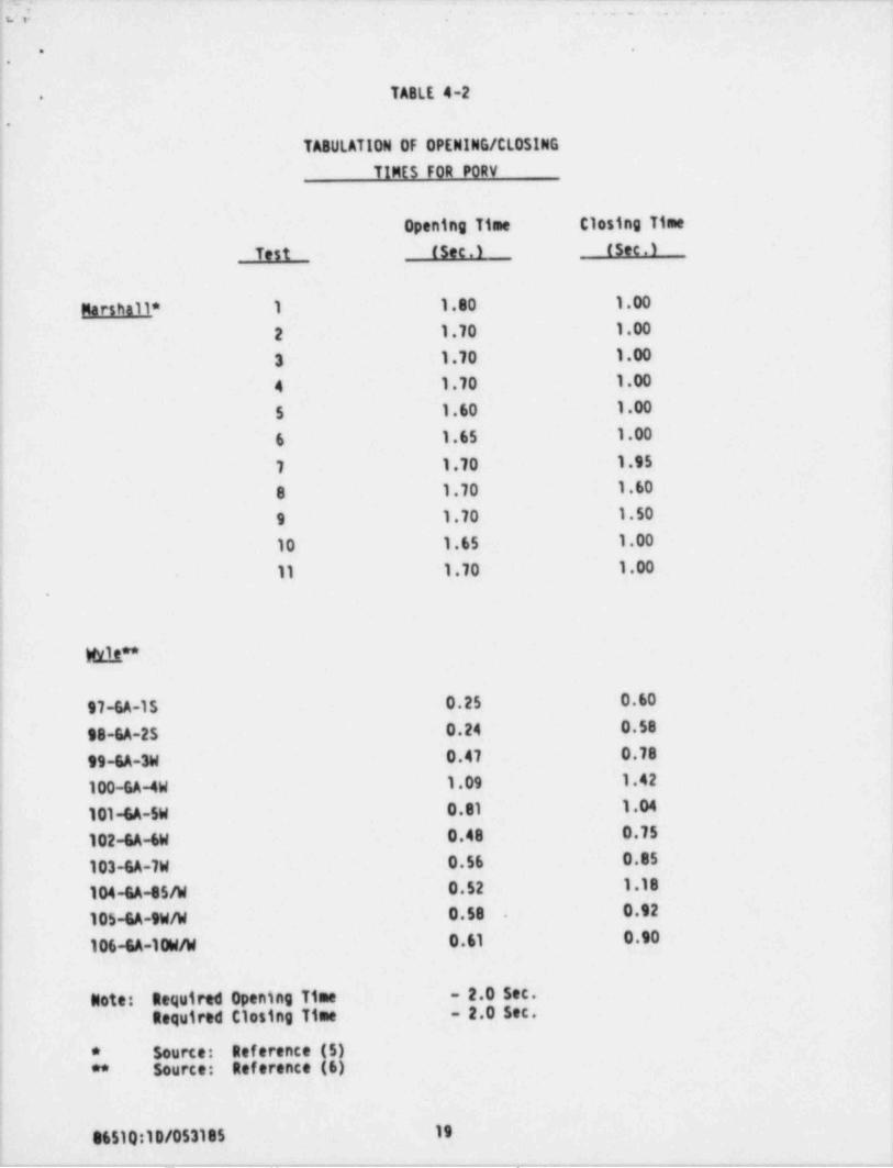
TA8LE 4-2-
.
TA80LATION OF OPENING / CLOSING'
TINES FOR PORV|,
Opening Time Closing Time
Test (Sec.) (sec.)'
Marshall * 1 1.80 1.00
2 1.70 1.00
3 1.70 1.00i
4 1.70 1.00
5 1.60 1.00
6 1.65 1.00;
7 1.70 1.95
8 1.70 1.60
9 1.70 1.50
10 1.65 1.00
11 1.70 1.00: -
i
(
W11t?*
97-6A-15 0.25 0.60
98-6A-25 0.24 0.58
99-6A-3W 0.47 0.78
100-6A-4W 1.09 1.42
| 101-GA-5W 0.81 1.04
102-GA-6W 0.48 0.75'
103-6A-7W 0.56 0.85
104-6A-85/W 0.52 1.18
105-6A-9W/W 0.58 0.92.
106-GA-10W/W 0.61 0.90
Note: Sequired Opening Time - 2.0 Sec.Sequired Closing Time - 2.0 Sec.
* Source: 8eference (5)** Source: 8eference (6);
:i
06510:10/053185 19
-. - . -_____ .- _ ._ -_ _ . .- - .._.- . _ _ _ - _ _ - _ . _ - . .-. ..

- - -
n.. - _..
.
.
TABLE 4-3-
.
COMPARISON OF SAFETY VALVE INLET FLUID
CONDITIONS WITH " AS-TESTE0' CONDITIONS
Tests 6M6
Safety Valve No. 906-913
Inlet Fluid 917-923, 925 1406
Conditions 1415 and 1419
Set Point 2500 2500
Pressure (psia) 1
Temperature 650 650
(*F)
Fluid Type Steam loop seal / steam
*Flow Rate 420.000
.
(1bs/hr)
Pressurization 130-144 1.1-375
Rate (psi /sec)
Stable **Stability
2455-2600Initial openingPressure (psia)
2455-2757 ,
Pop Pressure.
(psia)
Rated flow achieved but not reported in EPRI Tables, reference (7).*|
As reported by EPRI in Performance data tables of Reference (1).**
|[
96510:10/053185 20
__ .- . ._. _ _ -_. - . -. . ._ ._. .- .- __

uv . . . . . , .
.
l
TABLE 4-4-
..
MAXIMUM PERMISSISLE PRESSURE FOR
PRESSURIZER SAFETY VALVE INLET PIPING *
Outside Diameter Nominal Permissible
Pine Size fini Thickness fini Pressure insi)
Level B Level C
6-inch Sch.160 6.625 0.719 5229 7131
6-inch Sch. 120 6.625 0.562 4004 5460.
4-inch Sch.160 4.500 0.531 5733 1818
4-inch Sch.120 4.500 0.438 4644 6333
3-inch Sch.160 3.500 0.438 6119 8344
Source: Reference (9)
* Applicable for temperatures below 300*F.
i
.
06510:10/053185 21-- _. . _ .- . _- - _ . - . - - - . . .
._ . _ _ _ _ _ _ . _ _ , _ _ _ - _ _ - _ - - - .- _. ._ .-. - ._ -- _ _ . __
. . . . . . .
e
5.0 CONCLUSIONS-
;'The proceeding sections of this report and the reports referenced hereinindicate the valves, piping arrangements, and fluid inlet conditions forAlvin W. Vogtle Units 1 and Unit 2 are indeed bounded by those valves and testi
parameters of the EPRI Safety and Relief Valve Test Program. The EPAI tests,
confirm the ability of the safety and Relief Valves to open and close underthe expected operating fluid conditions.!
;
i
1
|
l1
i
,
1
|
i
j
;'
!,
|!
M510:10/053105 22,
-- -. .- . . - ._. -_. . _ . _ _ _ . . - _ . . _ _ _ _ - _ - . - _ _ . _ . _ _ _ . - - .

,
- - - - . . .:::.. . - -
u. . .
.
.
.
APPEND 1X
.
.
.
|'
.
|
|
86510:10/042585__ _ -
_. .. - - - . .-
...:....v+ . . . . .
'j.,
'
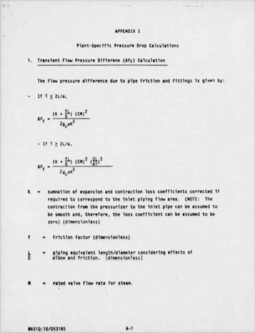
APPEN0!X I.
Plant-Specific pressure Drop Calculations
1. Transient F1w pressure Difforene (AP ) CalculationF
The f1w pressure difference due to pipe friction and fittings is given by:
If T $ 2L/a,-
(K+f)(CM)2! APF= 22gg
.
- If T > 2L/a,
|
(K+f)(CM)2 g 32
i
API= 2'
2g pAg
|
sustation of expansion and contraction loss coefficients corrected ifK =
required to correspond to the inlet piping f1w area. (NOTE: Thecontraction from the pressuriter to the inlet pipe can be assumed to
j
be smooth and, therefore, the loss coefficient can be assumed to bei aero) (dimensionless)
friction factor (dimensionless); f =
piping equivalent length / diameter considering effects ofL =
D elbow and friction. (dimensionless)
|.
rated valve f1w rate for steam. |M =
..
I
M510:10/053185 A-1_ _ _ _ __ _ __ _ __ _ _ __
'
.
.. . . . . . _.
.
..
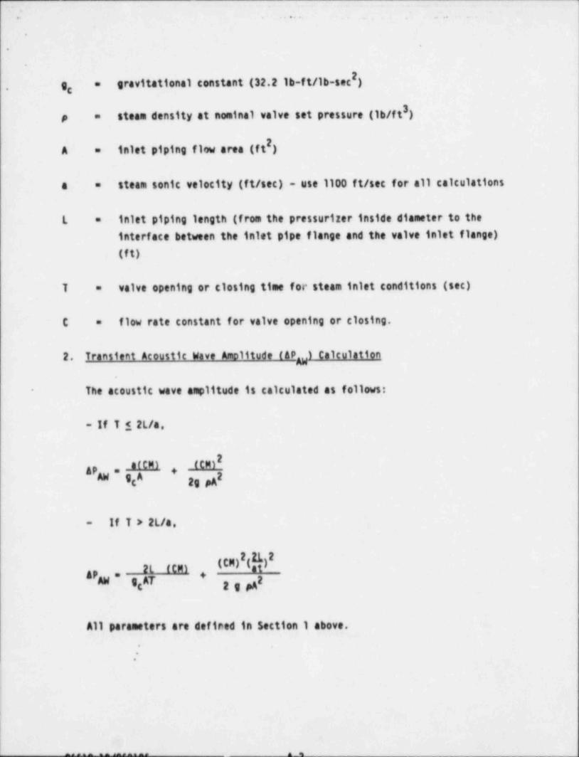
2g, gravitational constant (32.2 lb-ft/lb-sec )=
.
3steam density at nominal valve set pressure (1b/ft )p =
2inlet piping f1w area (f t )A =
steam Sonic velocity (ft/sec) - use 1100 f t/sec for all calculationsa =
inlet piping length (from the pressurizer inside diameter to theL =
interface between the inlet pipe flange and the valve inlet flange)
(ft)
valve opening or closing time for steam inlet conditions (sec)T =
flow rate constant for valve opening or closing.C =
2. Transient Acoustic Wave Amplitude ( APg) Calculation
The acoustic wave amplitude is calculated as follows:-
- If T 1 2L/a,
afCM) (CM)2AP +g= 2
If T > 2L/a,-
(CM) (b)2L (tm)8'AW " g AT 2 e pA
+tg
All parameters are defined in Section 1 above.
*
.
|
- -

~.......:.. ..: : . ."
.. .. .. ..
..
3. Plant-Soecific Transient Pressure Difference Calculation.
The plant-specific transient pressure difference associated with valveopening or closing is equal to the sum of the f1w pressure difference
(AP ) and the acoustic wave amplitude (&Pg) as determined above.p
4. Plant-Soecific Steadv-State F1 w Pressure Difference Calculation
The steady-state f1w pressure difforence associated with valve opening orclosing is given by:
(K +h) (CR)2AP -
F= 22gg
All parameters are defined in Section 1 above. Note that the values ofthe f1w rate constant. C are different for valve opening and closing.
a. Valve Opening-
From Table B-2, the opening time is.
T,,= .010 sec.
Also,
n . ip,;f; 't . 0i.s sec.
|
|
| Therefore. T, < 2L/a(1) Transient F1w Pressure Difforence
f
!
|''
.
06510:10/053105 A-3
- . _ - . _ - _ _ _ _ . _ _ _ . _ _ _ _ _ _ _ ._ ___.._ ___ _ _ - _ _ . _ __ _ _ .___. . _ _ !-
_

'I .: . . . . . . .. . .
.
.
Since T ,, < 2L/a, the following pressure difference is,,
(K + ft 0) (cm)2g, ,
2g pAg
where.116.7 lb/sec.420.000 lb/hr =
"3600 sec/hr
1.11C =
0 - see item 1 aboveK =
f .015=
l al + 1x(16) + 2 x(30) + 1(50) = 147L =
0 .432
37.65 lb/ftp =
20.147 ftA =
The Flow Pressure Difference is,
2IO+(.015) (14711M .11)(116.711API = 264.4 x 7.65 x .141 ,j44
app = 24.14 psi
(2) Transient Acoustic Wave Amplitude
i
!
i-
*
| .
M510:10/053105 A-4

. - - - _ - . _.. . - -- _- .
_
' ' ' '
., .
.
.
Since T,, < 2L/a, the Acoustic amplitude is.
(CM)2| gpAW , ALEEl , 2g pAgAg g
(1.11x116.7)EJ (1100) fl .11x1116.7) +=
32.2 x .147 x 144 264.4x7.65x.147 ,344 i
AP = 220 psigg
(3) Plant-Snecific Transient Pressure Difference
The plant-specific pressure difference for valve opening is,
app + APggAP =
:
24.14 + 220=
,
244.14 psiAP =.
|
! .
(4) Plant-$necific Pressure Difference
The steady-state flow pressure difference for valve opening is,
(K+Ih) (CM)2<
APp= 229 PAc
.
:
app = 24.14
,
.
.
i
j

- _ .__ _ _ . _ _ _ _ _ _ _ _ _ _ . _ _. .._ .._.__
;uv . .. . . . . .
.
(5) Plant-$necific pressure Difference for Plant Versus Test'
Eva*uation fopenina)
Based on the above, the controlling pressure difforence is thetransient pressure dif ference, 244.14 psi.
(b) Valve Closine
From Table B-2, the closing time is.
TCL = .016C .69
,
i Also, 2L/A = .0165 sec.
T $ .016 see 1 2L/aCL
(1) Transient Flow Pressure Difference is.
(K + h) (CM)AP =
2g Mg
0. + .015 x 147 x (.69 x 116.7) 2AP =
64.4 x 7.65 x .147 2 , 344
app = 9.33 psi:
i
!
"
.'
'- - - _ _ _ _ _ . _ _ - . . _ _ _ _ _ - - - - . _ _ _ _ _ _ - - - _ _ _ . _ _ __ __ __ __ _

. - . -- . _ _ . - -
hO .
.
.
(2) Transient Acoustic Wave Amo11tude.
Since T $ 2L/a, the acoustic wave amplitude is,CL
AP =O IENI4-8A 2g MC g
(1100) (.6tx116.7) (.69x116.7)2*" 32.2 x .147 x 144 264.4x7.65x141 ,344
APg = 133.3 psi
(3) Plant-Snecific Transient Pressure Difference
The plant-specific pressure dif forence for valve closing is.
AP = APg = 9.33 + 133.3 = 142.63 psi
(4) Plant-Soecific Steady-State Flow Pressure Difference-
The steady-state flow pressure difforence for valve closing is thesame as for valve opening (9.33 psi)
(5) Plant-Snecific Pressure Difference for Plant versus TestEvaluation (Closinni
'
Based on the above the controlling pressure difference for Vogtle isthe transient pressure difforence, i.e., 142.63 psi.
'.
:\
*
|
|
| 86510:10/053105 A-7_ _ _ _ _ _ - - . . - _ -
-. _ _ _ . . - - -
_
, b' O .
!'
!,. t
'
REFERENCES-
?
1. EPRI PWR Safety and' Relief Test Program Valve Selection / Justification |
Report, ' Interim Report, March 1982.*<
2. Westinghouse Electric Corporation Reptrt ' Valve Inlet Fluid - Conditionsfor Pressuriter Safety and Relief Valves in Westinghouse - Design Plants',Interim Report NP-2296-LO, March 1982.
;
{ 3. EPRI PWR Safety and Relief Valve Test Program. Description and Status,
i * Test Condition Justification Report". Interim Report, NP-2460-LO, June
1902.
? |
4. 'EPRI PWR Safety and Relief Valve Test Program, Description and Status', |
April 1982. t
; 5. 'EPRI - Marshall Power-0perated Relief Valve Interin Test Data Report:
1 EPRI NP-2144-LO, Interim Report, February 1982.'
i
6. 'EPR1/Wyle Power-0perated Relief Valve Test Report, Volume 11' EPRI*
NP-2670-LD, Interin Report, October 1982.
7. 'EPRI/CE PWR Safety Valve Test Report,' Volume 6. Interin ReportNP-2770-LO, March, 1983.
8. 'EPRI PWR Safety and Relief Valve Test Program Guide for Application ofValve Test Program Results to Plant-5pecific Evaluations", Interim Report,Revision 2. July 1982.
9. ' Review of Pressurizer Safety Valve Performance as Observed in the CPRI
Safety and Relief Valve Test Program', June 1982.
10. Crane Technical Paper No. 410, ' Flow of Fluids Through Valves. Fittings, ;
and Pipe", 1976.
1!.
!
l
:-|
,
e6510:10/053105 A-8
_ _ _ _ - -__ __ _ _ . _ . . _ _ _ _. _ . _ _ . - _ --_ _ _ _ - - . _ _.-_- _ --- _ __ _

_ _ _ _ . _ _ _ _ _ _ _ _ _ _ _ _ _ _ . _ _ _ _ _ _ . . . _ __ __ __
* . . .
I..
E
,
l',
I' PtNt SAFETY AND RELIEF VALyt,
TEST PROGRAM, PORY BLOCK VALVE
! AN QUACY REPORT
;
i FOR
|GEORGIA POWER COMPANY
ALVIN V0GTLE UNIT 5 1 ANO 2
! i
JUNE 1985!
ORIGINAL 155UE
!
x
Prepared by.
t
|R. M. Grayson
M# 7!/kPl'Verifled by
Approved by 9d/f[M.A. Sepp,Ma[er
.
Westinghouse Electric Corporation." puclear Energy Systems
P.O. Box 355Pittsburgh, PA 15230
,
. . . _ _ _ _, __ - _ . _ , _ , . . _ . . . _ _ . _ . . _ _ . _ - . - __ , _ _ _ , , , , _ , _ .
2+ _.. ;; ; . : --
.. . . .
*.
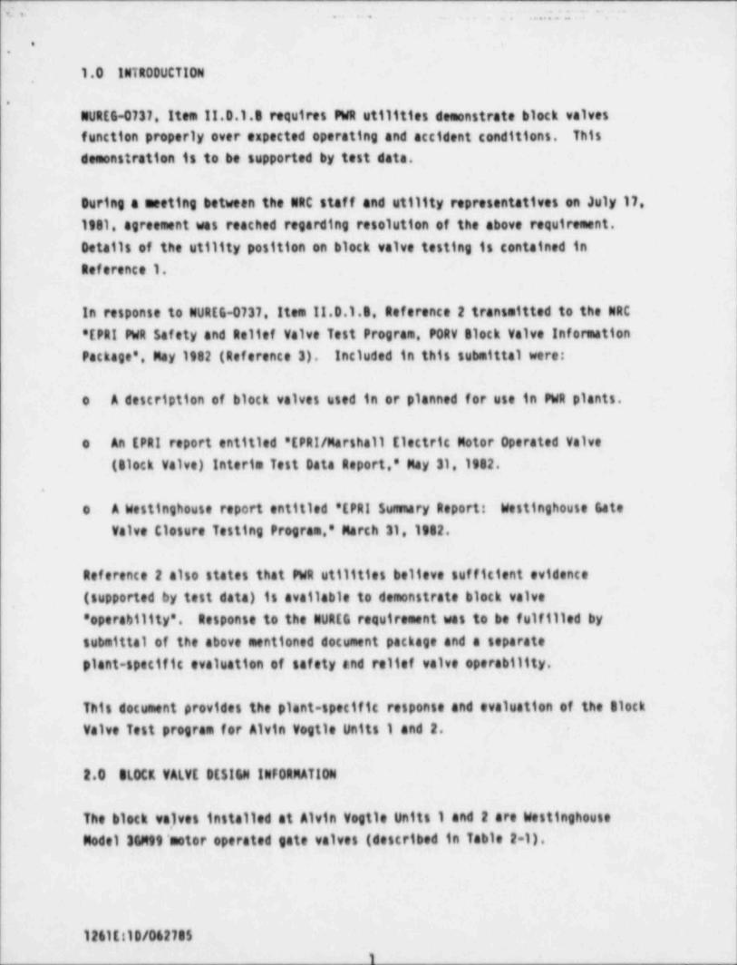
1.0 INTRODUCTION,
.
NUREE-0737, Item !!.D.1.5 requires FWR utilities demonstrate block valvesfunction properly over expected operating and accident conditions. Thisdemonstration is to be supported by test data.
During a meeting between the NRC staff and utility representatives on July 17,1981, agreement was reached regarding resolution of the above requirement.Details of the utility position on block valve testing is contained inReference 1.
In response to NUREG-0737. Item !!.0.1.5, Reference 2 transeitted to the NRC*EPRI PWR Safety and Relief Valve Test Program, p0RV Glock Valve Information
Package'. May 1982 (Reference 3), included in this submittal were:
o A description of block valves used in or planned for use in PWR plants,
o An EPRI report entitled 'EPRI/ Marshall Electric Motor Operated Valve(Block Valve) Interim Test Data Report,' May 31, 1982.
.
o A Westinghouse report entitled 'EPRI Summary Report: Westinghouse GateValve Closure Testing Program,' March 31, 1982.
Reference 2 also states that PWR utilities believe sufficient evidence(supported by test data) is available to demonstrate block valve' operability'. Response to the NUR[G requirement was to be fulfilled bysubmittal of the above mentioned document package and a separate
plant-specific evaluation of safety and relief valve operability.
This document provides the plant-specific response and evaluation of the tiockValve Test program for Alvin Vogtle Units 1 and 2. -
2.0 OLOCK VALVE DES!4N INFORMATION
The block va,1ves installed at Alvin Vogtle Units 1 and 2 are WestinghouseModel HMeg' motor operated gate valves (described in Table 2-1).
1261E:10/062705
0
_ . . .
6 .. , ,
.
.
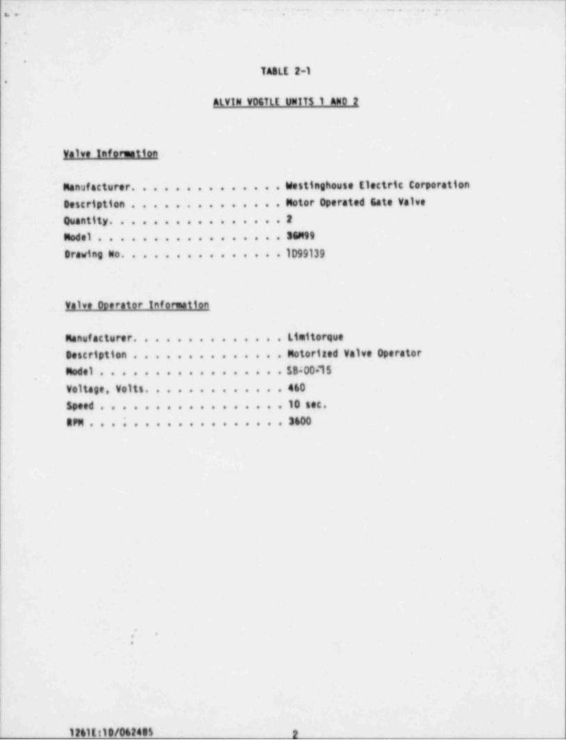
TA8LE 2-1.
ALVIN V0GTLE UNITS 1 AND 2
Valve Inforention
Manufacturer. . . . . . . . . . . . . . Westinghouse Electric CorporationDescription . . . . . . . . . . . . . . Motor Operated Gate ValveQuantity. . . . . . . . . . . . . . . 2
Model . . . . . . . . . . . . . . . . 3GM99
Orawing No. . . . . . . . . . . . . . 1D99139
Valve Operator Information
Manufacturer. . . . . . . . . . . . . . Limitorque
Description . . . . . . . . . . . . . . Motorized Valve OperatorModel . . . . . . . . . . . . . . . . . $B:00 15
,
voltage, Volts. . . . . . . . . . . . 460
Spe e d . . . . . . . . . . . . . . . . 10 s e c .
R PM . . . . . . . . . . . . . . . . . 3 600
.'-
.
I
!
|
|.
_ _ _ _ _ _ _ . _ _ _ . .

^^
'
. - . . - -. , . . . - . . .
*.
1:. TASLE 2-2 i
WESTINGHOUSE TEST VALVE DESCt1PT10N. TEST SERIES M-WS2**
General Valve Information
Manufacturer . . . . . . . . . . . . . Westinghouse Electric Corporation
! Description. . . . . . . . . . . . . . Motor Operated Este Valve
Model . . . . . . . . . . . . . . . . . M0003001EM99FNH02000 (99 Series)Se ri a l No . . . . . . . . . . . . . . 74004
Orawing No . . . . . . . . . . . . . . 9743030
'General Valve Operator Information
|
Manuf acturer . . . . . . . . . . . . . Limitorque
: Description. . . . . . . . . . . . . . Motorized Valve Operator-
Mod e l . . . . . . . . . . . . . . . . 5MS-000-10
se ri a l No . . . . . . . . . . . . . . . *Torque Switch Settleg. . . . . . . . . *
Voltage. . . . . . . . . . . . . . . 460
RPM. . . . . . . . . . . . . . . . . 3600
Not Supplied by the Manufacturer*
** Source: Reference 3
;
..
_ in1111A/061481

_ , , - .. .. - . ;__g . _ _....7-_.. -
, , , , ,
-|:
|..
During the EPRI Test program tests were conducted on a Westinghouse Model i.
'34M99 block valve at the Marshall test facility. Results of those tests are,
detailed in Reference 3.
i
For comparison a description of the Westinghouse test valves is provided in;
Table 2-2. As can be seen, the valves tested by EPRI are similar to the block
| valves installed at Vogtle.
3.0 SIMMARY OF SLOCK VALVE TEST RESULTS
3.1 WESTINGHOUSE SLOCK VALVE MODEL 3GM99
!
Results of the Westinghouse 3GM99 Block Valve Tests are contained in Section3.3 of Reference 3.
, ;
,
The Westinghouse 36M99 test valve was a 3-inch,1500-1b class valve with a
| Limitorque Model $N8-000-10 operator with a motor rated at 10 f t-1b torque.1 The 38M99 valve was tested in the horizontal configuration in line with the
Copes-Vulcan P0RY with 31655 plug and 17-4PH cage..
On January 12. 1901, 19 calibration and checkout cycles were run at;
; atmospheric conditions. During two additional full flow tests the valve didnot fully close. The valve was returned to the manufacturer for rework.
!
The SMS-000-10 limitorque motor operator was replaced with a model SMB-000-15,
operator, the yoke was redesigned and the motor operator was rowired to close.! on position instead of torque.
On January 28, 1981 22 pretest cycles were carried out and the evaluation test(21 cycles) conducted. After the evaluation test an additional 7 cycles werelegged on the valve. The evaluation tests are swanarized in Tables 3.3-2 and
| 3.3-3 of Reference 3.
l -
The Westinghouse 34 Met Test Valve, as modified with a SMS-000-15 Limitorque;
| motor operator, redesigned yoke and wired for limit closure, fully operated
and closed e' demand for the 21, cycles of the evaluation test. Uponn
!
!
1261E:10/062705._. _ _ _ - -- - - _ _ - _ _ . - -- - -- _

_ _ _ _ . . _ . . _ _ _ _ _ ._ _ ___ _._._
-
n- . . . . . . . .. . .. .. - . . = . . .
'
-
..
disassembly after all testing was complete the valve was inspected. There was'
slight galling of the wedge guides but all other components were in good,
'
condition.,
During the testing at Marshall on Westinghouse 3GM88 and 3GM99 Block Valves,the stem thrusts required to close the valves were measured using axial, type
stain gages. The resulting forces were considerably higher than expected.
! When subsequent closure problems occurred in Spain a series of tests and
| analyses were conducted by Westinghouse to determine the cause of the higherthan expected closing loads. A report of this testing and analysis iscontained in Reference 3.
,
|
This report concludes the closure problems encountered were the result ofunder-predicting the stem thrust required to close the valve against highdifferential pressures. The standard closing load equation used byWestinghouse has been appropriately modified based on these test results.
) 4.0 CONCt.USIONS
The Westinghouse valve tested at the Marshall Steam Station as part of the-
| EPRI Safety and Relief Valve test program is similar in design to the blockvalves installed at Alvin Vogtle Units 1 and 2 and this valve successfullycompleted the evaluation and supplementary test program, fully opening and
; closing on demand.
|' Furthermore, the Westinghouse model 3GM99 block valve installed at Vogtle has
been modified by Westinghouse to provide sufficient closing thrust as
| determined in the Westinghouse test program.|,
1
<
|
i
I
.'
1261E:10/062705
n
v ._ . . . . . , , - . ..
, , , _ _ ,
.
.
. 5.0 REFERENCES
.
1. Letter from R. C. Youngdahl, Consumers Power, to H. Denton, NRC dated
July 1,1981. ;'
2. Letter from R. C. Youngdahl Consumers Power to H. Denton, NRC. dated
June 1.1982.
3. "EPRI PWR Safety and Relief Valve Test Program PORY 81ock Valve
Information Package" dated May,1982.
4
1
i
.
:.
I
|
1261E:10/062785
_ _ _ _
n

![TOPIC: 191001 KNOWLEDGE: K1.01 [3.3/3.4] QID: …...NRC Generic Fundamentals Examination Question Bank--PWR May 2019-1- Valves TOPIC: 191001 KNOWLEDGE: K1.01 [3.3/3.4] QID: P901 Which](https://img.dokumen.tips/doc/110x75/5ed2f41a3e92a05e0d15d63e/topic-191001-knowledge-k101-3334-qid-nrc-generic-fundamentals-examination.jpg)


![TOPIC: 192004 KNOWLEDGE: K1.01 [3.1/3.2] QID: P133...NRC Generic Fundamentals Examination Question Bank--PWR November 2019-1- Reactivity Coefficients TOPIC: 192004 KNOWLEDGE: K1.01](https://img.dokumen.tips/doc/110x75/60d8d67d9d74587fe765ad25/topic-192004-knowledge-k101-3132-qid-p133-nrc-generic-fundamentals.jpg)

![TOPIC: 193006 KNOWLEDGE: K1.04 [3.4/3.6] QID: P78 · NRC Generic Fundamentals Examination Question Bank--PWR February 2017-1- Fluid Statics and Dynamics . TOPIC: 193006 . KNOWLEDGE:](https://img.dokumen.tips/doc/110x75/5adc4ee37f8b9a213e8b5d4a/topic-193006-knowledge-k104-3436-qid-p78-generic-fundamentals-examination.jpg)


![TOPIC: 193001 KNOWLEDGE: K1.01 [2.5/2.7] QID: P73 · NRC Generic Fundamentals Examination Question Bank--PWR May 2019-1- Thermodynamic Units and Properties . TOPIC: 193001 . KNOWLEDGE:](https://img.dokumen.tips/doc/110x75/5ffa16b0e65b8d6f6a779196/topic-193001-knowledge-k101-2527-qid-p73-nrc-generic-fundamentals-examination.jpg)


![TOPIC: 193008 KNOWLEDGE: K1.01 [2.8/3.0] QID: P986 · NRC Generic Fundamentals Examination Question Bank--PWR February 2017-13- Thermal Hydraulics TOPIC: 193008 . KNOWLEDGE: K1.03](https://img.dokumen.tips/doc/110x75/5aceab717f8b9ac1478bfb0a/topic-193008-knowledge-k101-2830-qid-p986-generic-fundamentals-examination.jpg)