Embed Size (px)
Citation preview
3436 0699 TACO
Record the following information from the motor and pump nameplates for future reference:
Pump Model No.
Bill of Material No.
Motor Model No.
Motor Serial No.
HP Volts/Hz/Ph
Rated Amp Draw
NOTE! Read and understand the pump and motor instructions before attempting to install, disassemble or repair the pump.
PVM – CAST IRONPVMX – 316 STAINLESS STEELSINGLE AND THREE PHASEVERTICAL MULTISTAGE PUMPSINSTALLATION AND OPERATING INSTRUCTIONS
Part # A-03-308 | © 2013 Pentair Ltd. | 10/09/13

VERTICAL MULTISTAGE PUMPS
2
TABLE OF CONTENTS:
Safety Instructions ...................................................................... 2Applications and Operating Ranges ........................................ 2–4Installation ............................................................................... 5–6Electrical ..................................................................................... 6Operation ................................................................................. 7–8Maintenance .......................................................................... 9–12Troubleshooting Guide ............................................................. 13Repair Parts ......................................................................... 14–17
Carefully read and follow all safety instructions in this manual or on pump.
This is the safety alert. When you see this symbol on your pump or in this manual, look for one of the following signal words and be alert to the potential for personal injury.
The word NOTICE indicates special instructions that are important but not related to hazards.
To avoid serious or fatal personal injury and possible property damage, carefully read and follow the safety instructions.
1. Install pump according to all code requirements.
2. Compare pump nameplate data with desired operating range.
3. Pump only liquids compatible with pump component materials (that is, liquids that will not attack the pump).
4. Make sure plumbing is adequate to handle system pressure.
5. Periodically perform maintenance inspection on pump and system components.
6. Wear safety glasses at all times when working on pumps.
INSPECT THE SHIPMENT:
The vertical multistage centrifugal in-line pump has been carefully inspected and packaged to assure safe delivery. Inspect the pump and fittings and report to the carrier any items that are damaged or missing.
CONFIRM THAT YOU HAVE THE RIGHT PUMP:
APPLICATIONS AND OPERATING RANGES:
Pentair multistage in-line centrifugal pumps are designed for liquid transfer, circulation, and pressure boosting of hot or cold clean water or other thin, nonexplosive liquids, not containing solid particles or fibers, which will not chemically attack the pump materials.
Typical applications include:
• Municipal water supply and pressure boosting
• Boiler feed and condensate systems
• Cooling water systems
• Irrigation
• Fire fighting
Maximum Ambient Temperature ........................... 104°F (40°C)
Liquid Temperature Range .......................................5°F to 250°F (–15°C to +121°C)
Maximum Permissible Operating Pressure Curves .......................................See Figure 4
Maximum Inlet Pressure: .........................................See Table III Table III shows the maximum permissible inlet pressure.
However, the actual inlet pressure plus the pressure when the pump is running against a closed valve must always be lower than the Maximum Permissible Operating Pressure.
Electrical Data ............................................. See motor nameplate
Dimensions and Port-to-Port Lengths ......... See Figures 2A, 2B, 3A and 3B
Danger: Warns about hazards that will cause serious personal injury, death or major property
damage if ignored.
Warning: Warns about hazards that can cause serious personal injury, death or major property
damage if ignored.
Caution: Warns about hazards that will or can cause minor personal injury or property damage if
ignored.
PVM_2-30/2Pentair VerticalMultistage Pump
Nominal flow rate in m3/hr(multiply by 4.4 to get GPM)Number of stages (÷ 10)Number of impellers – used only if pumphas fewer impellers than chambers (stages)
Material Code (SS only)X = all wetted surfaces 316SS
MODEL #
GPM
HP
PART #
FEETPRESS. MAX (PSI)
MFG. DATE
RPM
TEMP. MAX (F)
Figure 1. Model plate information.
Warning: California proposition 65 warning
This product and related accessories contain chemicals known to the State of California to cause cancer, birth defects or other reproductive harm.
VERTICAL MULTISTAGE PUMPS
3
3"
9-7/8"3-15/16"
7-1/16"8-1/4"
3-15/16"
8-1/4"
10"
1-1/4"NPT
ANSI 250 lb1-1/4" Flange
1/2" Dia. – 4 Places
EA
B
CD
EA
B
CD
F F
1/4" NPTGauge Tap
3/4" NPTVent Plug
Allow Spaceto Remove Motor
1/4" NPTGauge Tap
11-13/16"
5-1/8"5-1/8"
8-1/2"9-3/4"
3-1/2"
12-5/64"
2" NPT
ANSI 250 lb2" Flange
17/32" Dia. – 4 Places
E
B
D
A
C
E
B
D
A
C
F F
9-3/4"
Allow Spaceto Remove Motor
1/4" NPTGauge Tap
1/4" NPTGauge Tap
3/4" NPTVent Plug
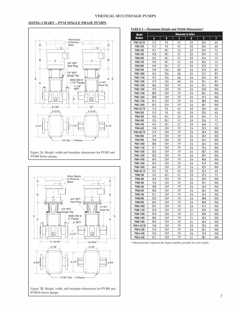
Figure 2B. Height, width, and baseplate dimensions for PVM8 and PVM16 Series pumps.
TABLE I – Maximum Height and Width Dimensions*
Model Number
Dimension in Inches A B C D E F
PVM2-30/2D 11.3 9.3 4.5 2.0 22.6 6.0PVM2-30D 11.3 9.3 4.5 2.0 22.6 6.0PVM2-40D 12.1 10.1 5.3 2.0 24.2 7.2PVM2-50D 12.8 10.1 5.7 2.0 24.9 7.2PVM2-60D 13.5 10.1 5.7 2.0 25.6 7.2PVM2-70D 14.2 10.1 5.7 2.0 26.3 7.2PVM2-80D 14.9 10.1 5.7 2.0 27.0 7.2PVM2-90D 15.8 12.6 6.8 2.6 31.0 8.9PVM2-100D 16.5 12.6 6.8 2.6 31.7 8.9PVM2-110D 17.2 12.6 6.8 2.6 32.4 8.9PVM2-120D 17.9 12.6 6.8 2.6 33.1 8.9PVM2-130D 18.6 13.9 7.9 2.6 35.1 10.0PVM2-140D 19.3 13.9 7.9 2.6 35.8 10.0PVM2-150D 20.0 13.9 7.9 2.6 36.5 10.0PVM2-160D 20.8 13.9 7.9 2.6 37.3 10.0PVM2-170D 21.5 13.9 7.9 2.6 38.0 10.0PVM2-180D 22.2 13.9 7.9 2.6 38.7 10.0PVM4-20/1D 11.3 9.3 4.5 2.0 22.6 6.0PVM4-20D 11.3 9.3 4.5 2.0 22.6 6.0PVM4-30D 12.4 10.1 5.3 2.0 24.5 7.2PVM4-40D 13.5 10.1 5.7 2.0 25.6 7.2PVM4-50D 14.5 10.1 5.7 2.0 26.6 7.2PVM4-60D 15.8 13.9 7.9 2.6 32.3 10.0
PVM4-80/7D 17.9 13.9 7.9 2.6 34.4 10.0PVM4-80D 17.9 13.9 7.9 2.6 34.4 10.0PVM4-90D 19.0 13.9 7.9 2.6 35.5 10.0PVM4-100D 20.0 13.9 7.9 2.6 36.5 10.0PVM4-110D 21.1 13.9 7.9 2.6 37.6 10.0PVM4-120D 22.2 13.9 7.9 2.6 38.7 10.0PVM4-130D 23.2 13.9 7.9 2.6 39.7 10.0PVM4-140D 24.3 13.9 7.9 2.6 40.8 10.0PVM4-150D 25.4 13.9 7.9 2.6 41.9 10.0PVM4-160D 26.4 13.9 7.9 2.6 42.9 10.0PVM8-20/1D 14.1 9.3 4.5 2.0 25.4 6.0PVM8-20D 15.2 10.1 5.7 2.0 27.3 7.2PVM8-30D 16.4 13.9 7.9 2.6 32.9 10.0PVM8-40D 17.6 13.9 7.9 2.6 34.1 10.0PVM8-50D 18.8 13.9 7.9 2.6 35.3 10.0PVM8-60D 20.0 13.9 7.9 2.6 36.5 10.0PVM8-70D 21.1 13.9 7.9 2.6 37.6 10.0PVM8-80D 22.3 13.9 7.9 2.6 38.8 10.0PVM8-90D 23.5 13.9 7.9 2.6 40.0 10.0PVM8-100D 24.7 13.9 7.9 2.6 41.2 10.0PVM8-110D 25.9 13.9 7.9 3.1 42.9 10.0PVM8-120D 27.0 13.9 7.9 3.1 44.0 10.0PVM8-130D 28.2 13.9 7.9 3.1 45.2 10.0PVM8-140D 29.4 13.9 7.9 3.1 46.4 10.0
PVM16-30/2D 15.8 13.9 7.9 2.6 32.3 10.0PVM16-30D 17.6 13.9 7.9 2.6 34.1 10.0PVM16-40D 19.4 13.9 7.9 2.6 35.9 10.0PVM16-50D 21.1 13.9 7.9 3.1 38.1 10.0
* Measurements represent the largest number possible for each model.
Figure 2A. Height, width and baseplate dimensions for PVM2 and PVM4 Series pumps.
SIZING CHART – PVM SINGLE PHASE PUMPS

VERTICAL MULTISTAGE PUMPS
4
3"
9-7/8"3-15/16"
7-3/32"8-3/16"
3-15/16"
8-3/16"
8-1/4"
ANSI 250 lb1-1/4" Flange
17/32" Dia. – 4 Places
EA
B
CD
EA
B
D
F
C
F
Allow Spaceto Remove Motor
1-1/4"Victaulic
Vent Plugbehind
Coupling Guard
11-13/16"
5-1/8"5-1/8"
8-1/2"9-5/8"
3-1/2"
2" Victaulic
ANSI 250 lb2" Flange
17/32" Dia. – 4 Places
E
B
D
A
C
E
B
D
A
C
F F
9-5/8"
Allow Spaceto Remove Motor
3/4" NPTVent Plug
10-1/4"
Figure 3B. Height, width, and baseplate dimensions for PVMX8 and PVMX16 Series pumps.
TABLE II – Maximum Height and Width Dimensions*Model
NumberDimension in Inches
A B C D E FPVM2-30/2D 11.3 9.3 5.2 2.0 22.6 6.2PVM2-30D 11.3 9.3 5.2 2.0 22.6 6.2PVM2-40D 12.1 9.3 5.2 2.0 23.4 6.2PVM2-50D 12.8 10.1 5.7 2.0 24.9 7.2PVM2-60D 13.5 10.1 5.7 2.0 25.6 7.2PVM2-70D 14.2 10.1 5.7 2.0 26.3 7.2PVM2-80D 14.9 10.1 5.7 2.0 27.0 7.2PVM2-90D 15.8 12.6 6.9 2.6 31.0 8.6PVM2-100D 16.5 12.6 6.9 2.6 31.7 8.6PVM2-110D 17.2 12.6 6.9 2.6 32.4 8.6PVM2-120D 17.9 12.6 6.9 2.6 33.1 8.6PVM2-130D 18.6 12.6 6.9 2.6 33.8 8.6PVM2-140D 19.3 12.6 6.9 2.6 34.5 8.6PVM2-150D 20.0 12.6 6.9 2.6 35.2 8.6PVM2-160D 20.8 12.6 6.9 2.6 36.0 8.6PVM2-170D 21.5 12.6 6.9 2.6 36.7 8.6PVM2-180D 22.2 12.6 6.9 2.6 37.4 8.6PVM4-20/1D 11.3 9.3 5.2 2.0 22.6 6.2PVM4-20D 11.3 9.3 5.2 2.0 22.6 6.2PVM4-30D 12.4 9.3 5.2 2.0 23.7 6.2PVM4-40D 13.5 10.1 5.7 2.0 25.6 7.2PVM4-50D 14.5 10.1 5.7 2.0 26.6 7.2PVM4-60D 15.8 12.6 6.9 2.6 31.0 8.6
PVM4-80/7D 17.9 12.6 6.9 2.6 33.1 8.6PVM4-80D 17.9 12.6 6.9 2.6 33.1 8.6PVM4-90D 19.0 12.6 6.9 2.6 34.2 8.6PVM4-100D 20.0 12.6 6.9 2.6 35.2 8.6PVM4-110D 21.1 12.6 6.9 2.6 36.3 8.6PVM4-120D 22.2 12.6 6.9 2.6 37.4 8.6PVM4-130D 23.2 12.6 6.9 2.6 38.4 8.6PVM4-140D 24.3 12.6 6.9 2.6 39.5 8.6PVM4-150D 25.4 13.9 8.1 2.6 41.9 10.3PVM4-160D 26.4 13.9 8.1 2.6 42.9 10.3PVM8-20/1D 14.1 9.3 4.5 2.0 25.4 6.0PVM8-20D 15.2 10.1 5.7 2.0 27.3 7.2PVM8-30D 16.4 12.6 6.9 2.6 31.6 8.6PVM8-40D 17.6 12.6 6.9 2.6 32.8 8.6PVM8-50D 18.8 12.6 6.9 2.6 34.0 8.6PVM8-60D 20.0 12.6 6.9 2.6 35.2 8.6PVM8-70D 21.1 13.9 8.1 2.6 37.6 10.3PVM8-80D 22.3 13.9 8.1 2.6 38.8 10.3PVM8-90D 23.5 13.9 8.1 2.6 40.0 10.3PVM8-100D 24.7 13.9 8.1 2.6 41.2 10.3PVM8-110D 25.9 14.2 8.1 3.1 43.2 10.3PVM8-120D 27.0 14.2 8.1 3.1 44.3 10.3PVM8-130D 28.2 14.2 8.1 3.1 45.5 10.3PVM8-140D 29.4 14.2 8.1 3.1 46.7 10.3PVM8-160D 32.3 20.0 9.5 4.0 56.3 12.9PVM8-160D 32.3 20.0 9.5 4.0 56.3 12.9
PVM16-30/2D 15.8 12.6 6.9 2.6 31.0 8.6PVM16-30D 17.6 13.9 8.1 2.6 34.1 10.3PVM16-40D 19.4 13.9 8.1 2.6 35.9 10.3PVM16-50D 21.1 14.2 8.1 3.1 38.4 10.3PVM16-60D 23.4 20.0 9.5 4.0 47.4 12.9PVM16-70D 25.2 20.0 9.5 4.0 49.2 12.9PVM16-80D 27.0 20.0 9.5 4.0 51.0 12.9PVM16-90D 28.7 16.9 9.2 3.8 49.4 11.5
PVM16-100D 30.5 16.9 9.2 3.8 51.2 11.5PVM16-110D 31.6 20.0 9.5 3.0 54.6 13.3PVM16-120D 33.4 20.0 9.5 3.0 56.4 13.3PVM16-130D 35.2 20.0 9.5 3.0 58.2 13.3
* Measurements represent the largest number possible for each model.NOTICE: PVMX models are 316 stainless steel.
Figure 3A. Height, width and baseplate dimensions for PVMX2 and PVMX4 Series pumps.
SIZING CHART – PVM THREE PHASE PUMPS

VERTICAL MULTISTAGE PUMPS
5
3"
9-7/8"3-15/16"
7-1/16"8-1/4"
3-15/16"
8-1/4"
10"
1-1/4"NPT
ANSI 250 lb1-1/4" Flange
1/2" Dia. – 4 Places
EA
B
CD
EA
B
CD
F F
1/4" NPTGauge Tap
3/4" NPTVent Plug
Allow Spaceto Remove Motor
1/4" NPTGauge Tap
11-13/16"
5-1/8"5-1/8"
8-1/2"9-3/4"
3-1/2"
12-5/64"
2" NPT
ANSI 250 lb2" Flange
17/32" Dia. – 4 Places
E
B
D
A
C
E
B
D
A
C
F F
9-3/4"
Allow Spaceto Remove Motor
1/4" NPTGauge Tap
1/4" NPTGauge Tap
3/4" NPTVent Plug
Figure 2B. Height, width, and baseplate dimensions for PVM8 and PVM16 Series pumps.
TABLE I – Maximum Height and Width Dimensions*
Model Number
Dimension in Inches A B C D E F
PVMX2-30/2D 11.9 9.3 4.5 2.0 23.2 6.0PVMX2-30D 11.9 9.3 4.5 2.0 23.2 6.0PVMX2-40D 12.6 10.1 5.3 2.0 24.7 7.2PVMX2-50D 13.3 10.1 5.7 2.0 25.4 7.2PVMX2-60D 14.1 10.1 5.7 2.0 26.2 7.2PVMX2-70D 14.8 10.1 5.7 2.0 26.9 7.2PVMX2-80D 15.5 10.1 5.7 2.0 27.6 7.2PVMX2-90D 16.2 12.6 6.8 2.6 31.4 8.9PVMX2-100D 16.9 12.6 6.8 2.6 32.1 8.9PVMX2-110D 17.6 12.6 6.8 2.6 32.8 8.9PVMX2-120D 18.3 12.6 6.8 2.6 33.5 8.9PVMX2-130D 19.0 13.9 7.9 2.6 35.5 10.0PVMX2-140D 19.7 13.9 7.9 2.6 36.2 10.0PVMX2-150D 20.4 13.9 7.9 2.6 36.9 10.0PVMX2-160D 21.1 13.9 7.9 2.6 37.6 10.0PVMX2-170D 21.8 13.9 7.9 2.6 38.3 10.0PVMX2-180D 22.6 13.9 7.9 2.6 39.1 10.0PVMX4-20/1D 11.7 9.3 4.5 2.0 23.0 6.0
PVMX4-20D 11.7 9.3 4.5 2.0 23.0 6.0PVMX4-30D 12.8 10.1 5.3 2.0 24.9 7.2PVMX4-40D 13.9 10.1 5.7 2.0 26.0 7.2PVMX4-50D 14.9 10.1 5.7 2.0 27.0 7.2PVMX4-60D 16.0 13.9 7.9 2.6 32.5 10.0
PVMX4-80/7D 18.1 13.9 7.9 2.6 34.6 10.0PVMX4-80D 18.1 13.9 7.9 2.6 34.6 10.0PVMX4-90D 19.2 13.9 7.9 2.6 35.7 10.0PVMX4-100D 20.2 13.9 7.9 2.6 36.7 10.0PVMX4-110D 21.3 13.9 7.9 2.6 37.8 10.0PVMX4-120D 22.4 13.9 7.9 2.6 38.9 10.0PVMX4-130D 23.4 13.9 7.9 2.6 39.9 10.0PVMX4-140D 24.5 13.9 7.9 2.6 41.0 10.0PVMX4-150D 25.5 13.9 7.9 2.6 42.0 10.0PVMX4-160D 26.6 13.9 7.9 2.6 43.1 10.0PVMX8-20/1D 14.1 9.3 4.5 2.0 25.4 6.0
PVMX8-20D 15.2 10.1 5.7 2.0 27.3 7.2PVMX8-30D 16.4 13.9 7.9 2.6 32.9 10.0PVMX8-40D 17.6 13.9 7.9 2.6 34.1 10.0PVMX8-50D 18.8 13.9 7.9 2.6 35.3 10.0PVMX8-60D 20.0 13.9 7.9 2.6 36.5 10.0PVMX8-70D 21.1 13.9 7.9 2.6 37.6 10.0PVMX8-80D 22.3 13.9 7.9 2.6 38.8 10.0PVMX8-90D 23.5 13.9 7.9 2.6 40.0 10.0PVMX8-100D 24.7 13.9 7.9 2.6 41.2 10.0PVMX8-110D 25.9 13.9 7.9 3.1 42.9 10.0PVMX8-120D 27.0 13.9 7.9 3.1 44.0 10.0PVMX8-130D 28.2 13.9 7.9 3.1 45.2 10.0PVMX8-140D 29.4 13.9 7.9 3.1 46.4 10.0
PVMX16-30/2D 15.8 13.9 7.9 2.6 32.3 10.0PVMX16-30D 17.6 13.9 7.9 2.6 34.1 10.0PVMX16-40D 19.4 13.9 7.9 2.6 35.9 10.0PVMX16-50D 21.1 13.9 7.9 3.1 38.1 10.0
* Measurements represent the largest number possible for each model.
Figure 2A. Height, width and baseplate dimensions for PVM2 and PVM4 Series pumps.
SIZING CHART – PVMX SINGLE PHASE PUMPS

VERTICAL MULTISTAGE PUMPS
6
3"
9-7/8"3-15/16"
7-3/32"8-3/16"
3-15/16"
8-3/16"
8-1/4"
ANSI 250 lb1-1/4" Flange
17/32" Dia. – 4 Places
EA
B
CD
EA
B
D
F
C
F
Allow Spaceto Remove Motor
1-1/4"Victaulic
Vent Plugbehind
Coupling Guard
11-13/16"
5-1/8"5-1/8"
8-1/2"9-5/8"
3-1/2"
2" Victaulic
ANSI 250 lb2" Flange
17/32" Dia. – 4 Places
E
B
D
A
C
E
B
D
A
C
F F
9-5/8"
Allow Spaceto Remove Motor
3/4" NPTVent Plug
10-1/4"
Figure 3B. Height, width, and baseplate dimensions for PVMX8 and PVMX16 Series pumps.
TABLE II – Maximum Height and Width Dimensions*Model
NumberDimension in Inches
A B C D E FPVMX2-30/2D 11.9 9.3 5.2 2.0 23.2 6.2PVMX2-30D 11.9 9.3 5.2 2.0 23.2 6.2PVMX2-40D 12.6 9.3 5.2 2.0 23.9 6.2PVMX2-50D 13.3 10.1 5.7 2.0 25.4 7.2PVMX2-60D 14.1 10.1 5.7 2.0 26.2 7.2PVMX2-70D 14.8 10.1 5.7 2.0 26.9 7.2PVMX2-80D 15.5 10.1 5.7 2.0 27.6 7.2PVMX2-90D 16.2 12.6 6.9 2.6 31.4 8.6PVMX2-100D 16.9 12.6 6.9 2.6 32.1 8.6PVMX2-110D 17.6 12.6 6.9 2.6 32.8 8.6PVMX2-120D 18.3 12.6 6.9 2.6 33.5 8.6PVMX2-130D 19.0 12.6 6.9 2.6 34.2 8.6PVMX2-140D 19.7 12.6 6.9 2.6 34.9 8.6PVMX2-150D 20.4 12.6 6.9 2.6 35.6 8.6PVMX2-160D 21.1 12.6 6.9 2.6 36.3 8.6PVMX2-170D 21.8 12.6 6.9 2.6 37.0 8.6PVMX2-180D 22.6 12.6 6.9 2.6 37.8 8.6PVMX4-20/1D 11.7 9.3 5.2 2.0 23.0 6.2PVMX4-20D 11.7 9.3 5.2 2.0 23.0 6.2PVMX4-30D 12.8 9.3 5.2 2.0 24.1 6.2PVMX4-40D 13.9 10.1 5.7 2.0 26.0 7.2PVMX4-50D 14.9 10.1 5.7 2.0 27.0 7.2PVMX4-60D 16.0 12.6 6.9 2.6 31.2 8.6
PVMX4-80/7D 18.1 12.6 6.9 2.6 33.3 8.6PVMX4-80D 18.1 12.6 6.9 2.6 33.3 8.6PVMX4-90D 19.2 12.6 6.9 2.6 34.4 8.6PVMX4-100D 20.2 12.6 6.9 2.6 35.4 8.6PVMX4-110D 21.3 12.6 6.9 2.6 36.5 8.6PVMX4-120D 22.4 12.6 6.9 2.6 37.6 8.6PVMX4-130D 23.4 12.6 6.9 2.6 38.6 8.6PVMX4-140D 24.5 12.6 6.9 2.6 39.7 8.6PVMX4-150D 25.5 13.9 8.1 2.6 42.0 10.3PVMX4-160D 26.6 13.9 8.1 2.6 43.1 10.3PVMX8-20/1D 14.1 9.3 4.5 2.0 25.4 6.0PVMX8-20D 15.2 10.1 5.7 2.0 27.3 7.2PVMX8-30D 16.4 12.6 6.9 2.6 31.6 8.6PVMX8-40D 17.6 12.6 6.9 2.6 32.8 8.6PVMX8-50D 18.8 12.6 6.9 2.6 34.0 8.6PVMX8-60D 20.0 12.6 6.9 2.6 35.2 8.6PVMX8-70D 21.1 13.9 8.1 2.6 37.6 10.3PVMX8-80D 22.3 13.9 8.1 2.6 38.8 10.3PVMX8-90D 23.5 13.9 8.1 2.6 40.0 10.3
PVMX8-100D 24.7 13.9 8.1 2.6 41.2 10.3PVMX8-110D 25.9 14.2 8.1 3.1 43.2 10.3PVMX8-120D 27.0 14.2 8.1 3.1 44.3 10.3PVMX8-130D 28.2 14.2 8.1 3.1 45.5 10.3PVMX8-140D 29.4 14.2 8.1 3.1 46.7 10.3PVMX8-150D 31.1 20.0 9.5 4.0 55.1 12.9PVMX8-160D 32.3 20.0 9.5 4.0 56.3 12.9
PVMX16-30/2D 15.8 12.6 6.9 2.6 31.0 8.6PVMX16-30D 17.6 13.9 8.1 2.6 34.1 10.3PVMX16-40D 19.4 13.9 8.1 2.6 35.9 10.3PVMX16-50D 21.1 14.2 8.1 3.1 38.4 10.3PVMX16-60D 23.4 20.0 9.5 4.0 47.4 12.9PVMX16-70D 25.2 20.0 9.5 4.0 49.2 12.9PVMX16-80D 27.0 20.0 9.5 4.0 51.0 12.9PVMX16-90D 28.7 16.9 9.2 3.8 49.4 11.5PVMX16-100D 30.5 16.9 9.2 3.8 51.2 11.5PVMX16-110D 31.6 20.0 9.5 3.0 54.6 13.3PVMX16-120D 33.4 20.0 9.5 3.0 56.4 13.3PVMX16-130D 35.2 20.0 9.5 3.0 58.2 13.3
* Measurements represent the largest number possible for each model.NOTICE: PVMX models are 316 stainless steel.
Figure 3A. Height, width and baseplate dimensions for PVMX2 and PVMX4 Series pumps.
SIZING CHART – PVMX THREE PHASE PUMPS

VERTICAL MULTISTAGE PUMPS
7
TABLE III – Permissible Operating Pressure Curves
Curve 1 Curve 2
PVM2-30/2 to PVM2-120 PVM2-150 to PVM2-180
PVM4-20/1 to PVM4-120 PVM4-140 to PVM4-160
PVM8-20/1 to PVM8-120 PVM8-140 to PVM8-160
PVM16-30/2 to PVM16-80 PVM16-100 to PVM16-120
Model NumberMaximum InletPressure (PSI)
PVM2 30/2 - 6070 - 180
145220
PVM420/1 - 2030 - 80/780 - 160
90145220
PVM8 20/1 - 4050 - 160
90145
PVM16 30/2 - 3040 - 120
90145
INSTALLATION:
LOCATION. Locate pump in a dry, well ventilated area, not subject to freezing or extreme variations in temperature.
Mount pump a minimum of 6" from any obstruction or hot surface. Install the pump with the motor shaft vertical. Make sure that an adequate supply of cool air reaches the motor cooling fan. Maximum ambient air temperature is 104° F (40° C).
For open systems requiring suction lift, locate the pump as close to the water source as possible.
FOUNDATION. Foundation should be concrete or a similarly rigid foundation to provide a secure, stable mounting base for the pump.
Secure pump to foundation using all bolt holes. Refer to Figures 2 and 3 for bolt plate dimensions. Be sure that all four pads on the base are properly supported.
Shim pump base to make sure that pump is level.
PIPING:
If there is any danger of the pump running against a closed discharge valve, install a pressure relief or bypass valve in the discharge pipe to allow for minimum liquid flow through the pump. Minimum liquid flow through the pump is needed for cooling and lubrication of the pump (see Table IV). Run the bypass/relief valve and discharge pipe to a floor drain or a tank for collection.
Suction pipe should be adequately sized (see Table V) and run as straight and as short as possible to keep friction losses to a minimum. Pipes, valves, and fittings must have a pressure rating equal to or greater than the maximum system pressure.
TABLE IV – Minimum Pumping Rates
Type Liquid Temperature+5° F to +250° F
PVM2 1 GPM
PVM4 2 GPM
PVM8 4 GPM
PVM16 8 GPM
TABLE V – Minimum Suction Pipe Sizes
Type Pipe Size
PVM2 1-1/4" Nominal Diameter, Schedule 40 Pipe
PVM4 1-1/4" Nominal Diameter, Schedule 40 Pipe
PVM8 2" Nominal Diameter, Schedule 40 Pipe
PVM16 2" Nominal Diameter, Schedule 40 Pipe
Pressure check the discharge piping as required by codes or local regulations.
“Inlet” and “Outlet” are marked on the pump base to show the direction of the liquid flow through the pump.
Install antivibration mountings on either side of the pump if a minimum noise level is desired.
Figure 4. Maximum Inlet Pressure and Maximum Permissible Operating Pressure Curves.
Warning: Hazardous Voltage
Voltage can shock, burn, or cause death. Ground pump motor correctly before connecting to power supply, per article 250-80 of the National Electrical Code (NEC) in the U.S., or the Canadian Electrical Code (CEC), as applicable.
Warning: Explosion and Burn Hazard
Do not run pump with discharge valve closed; the water in the pump may boil, with risk of explosion and steam burns to anyone near.
0306090120150180210240270300330360390420
2120 to100 120 140 160 180 200 220 240
250260 280
Pres
sure
in P
SI
Temperature in Degrees F

VERTICAL MULTISTAGE PUMPS
8
Install isolation valves in both inlet and outlet pipes near the pump (see Figure 5). This allows for removal of pump for service without draining the system and isolation of the pump in case of a flooded suction condition.
If the system pressure is greater than the pump’s maximum inlet pressure, the limits of the pump can be exceeded if the discharge pressure backs up to the inlet side of the pump. Installation of a check valve in the discharge pipe is recommended to prevent this condition.
Make sure, especially on the inlet side of the pump, that there are no airlocks in the system. See Figure 6 for correct pipe work to avoid airlocks. The suction pipe should be level or slightly rising.
Support all piping independently of the pump so the weight of the piping system does not strain the pump case. Make sure that the expansion and contraction of the piping system from temperature variations cannot put a strain on the pump.
If the system or pump must be drained periodically (especially if the discharge pipe is horizontal or slopes downward away from the pump), install a loop and vacuum valve as shown in Figure 7 to protect the pump against running dry. The highest point of the loop should be at least as high as the lowest point of the motor. This loop/valve combination will allow the pump and the system to be drained independently of one another.
ELECTRICAL:
All electrical work should be performed by a qualified electrician in accordance with the National Electrical Code and all local codes and regulations. Make sure that the motor voltage, phase, and frequency match the incoming electrical supply. The proper operating voltage and other electrical information can be found on the motor nameplate. These motors are designed to run up to ±10% of the nameplate-rated voltage. The wiring connection diagram can be found on either a plate attached to the motor or on a diagram inside the terminal box cover.
• If voltage variations are greater than ±10%, do not operate the pump.
• Incorrect voltage can cause fire or serious damage to the motor and voids warranty.
• Ground the pump motor correctly before connecting it to the power supply.
• Follow the wiring instructions when connecting the motor to the power lines.
POSITION OF TERMINAL BOX. To turn the motor so that the terminal box faces the right direction, proceed as follows:
1. Disconnect the power to the pump motor.
2. Remove the coupling guards (use a screwdriver).
3. Remove the couplings.
4. Remove the bolts that fasten the motor to the pump.
5. Turn the motor to the required position (in quarter-turn increments).
6. Follow steps 10–20 under Motor Replacement.
Figure 5. Bypass required if pump might operate with discharge valve closed. See Table IV for minimum required flow through pump to prevent overheating and to ensure lubrication.
Inlet Outlet
NippleOrifice
Bypass Line
12" Min. to prevent
erosion
Isolation Valves
O.K.
O.K.
Figure 6. Install pipe correctly to prevent air locks.
Warning: Hazardous Voltage
Can shock, burn, or cause death.
Vacuum Valve
Figure 7. Loop and Vacuum Valve Installation.

VERTICAL MULTISTAGE PUMPS
9
FIELD WIRING. All wiring connections and wiring sizes must meet National Electrical Code and local requirements.
MOTOR PROTECTION. See the motor nameplate for electrical connection/wiring diagram.
Pentair pumps must be used with the proper size and type of motor starter to ensure protection against damage from low voltage, phase failure, current imbalances, and overloads. The overload should be sized to trip at the full-load current rating of the motor.
OPERATION:
PRIMING.
NOTICE: Under no circumstances should the pump be operated without flow through the pump. Never operate the pump dry.
Operation of closed systems or open systems with the liquid level above the pump priming plug:
1. Close the discharge isolating valve and loosen the needle valve located in the assembly in the pump head (Figure 8). Do not remove the needle valve.
NOTICE: On PVM(X)2/4 models, remove the coupling guard for access to the vent plug.
2. Slowly open the isolation valve in the suction pipe until a
steady stream of liquid runs out the vent in the priming port.
3. Tighten needle valve to 25 in.-lbs. Completely open isolation valves.
NOTICE: Please turn to Starting before proceeding any further.
Operation of open systems with the liquid level below the top of the pump:
NOTICE: The suction pipe requires a check valve or isolation valve.
1. Close the discharge isolation valve.
2. Remove the vented priming plug.
3. Pour liquid through the priming port until the suction pipe and the pump are completely filled with liquid.
4. Replace the vented priming plug and tighten it securely.
5. Repeat steps 1–4 until the pump is primed.
NOTICE: Please turn to Starting before proceeding any further.
CHECKING DIRECTION OF ROTATION. NOTICE: Do not disconnect the motor from the shaft to check the direction of rotation. If you remove the coupling, then you must adjust the shaft position when you reinstall it. This must be done before starting the pump.
Arrows on the pump head show the correct direction of rotation. When seen from the motor fan, the pump should rotate counterclockwise ( ). For pump motors without a fan, remove one of the coupling guards and look at the coupling to determine the direction of rotation. Turn off the pump and replace coupling guard.
NOTICE: Do not check the direction of rotation until the pump has been filled with liquid. See Priming.
1. Switch power off.
2. Remove the coupling guard and rotate the pump shaft to be certain it can turn freely. Replace the coupling guard.
3. Verify that the electrical connections are in accordance with the wiring diagram on the motor.
4. If the fan is visible, turn on and off to verify rotation.
5. To reverse the direction of rotation, first switch OFF the power supply.
6. On three-phase motors, switch 2 of the 3 power leads on the load side of the starter. On single-phase motors, see the connection diagram on the motor nameplate. Change the wiring as indicated.
Warning: Hazardous Pressure
Do not run the pump with the discharge valve closed; the water in the pump may boil, causing risk of explosion and steam burns to anyone nearby.
Warning: Hazardous Voltage
Disconnect all power to the pump before servicing or working on the pump. Make sure that the power is locked out and that the pump cannot be accidentally started.
VentedPrimingPlug
DrainPlug
Back off needle valve to vent air. Retighten to 25 in.-lbs. when vent port runs a steady stream of water.
Figure 8. Priming and drain plugs.
Warning: Risk of Water Damage and Injury
Watch the direction of the priming plug and make sure that the liquid escaping from it does not injure persons nearby or damage the motor or other components. In hot water installations, pay particular attention to the risk of injury from scalding hot water.
VERTICAL MULTISTAGE PUMPS
10
7. Switch on the power supply and recheck the direction of motor rotation.
STARTING.
1. If a suction line isolation valve has been installed, check to be sure that it is completely opened.
2. For initial starting, the isolation valve in the discharge pipe should be almost closed.
3. Start the pump.
4. When the piping system has been filled with liquid, slowly open the discharge isolation valve until it is completely open. Opening the valve too fast may result in water hammer in the discharge pipe. If the pump or system starts to rattle, the pump is cavitating; to avoid damage to the pump, reduce the flow through the discharge isolation valve until the rattling stops. If this does not give adequate flow for your installation, call your installer or system designer.
5. Record the voltage and amperage of the motor. Adjust the motor overloads if required.
6. If pressure gauges have been installed, check and record operating pressures.
7. Check all controls for proper operation.
MOTOR BEARINGS. For the greasing schedule and greasing procedure of the motor bearings, follow the motor manufacturer’s recommendations.
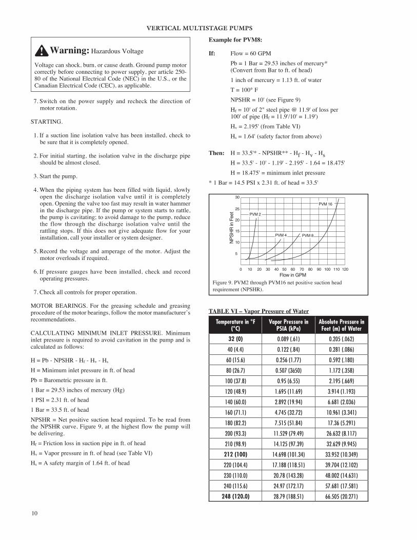
CALCULATING MINIMUM INLET PRESSURE. Minimum inlet pressure is required to avoid cavitation in the pump and is calculated as follows:
H = Pb - NPSHR - Hf - Hv - Hs
H = Minimum inlet pressure in ft. of headPb = Barometric pressure in ft.1 Bar = 29.53 inches of mercury (Hg)1 PSI = 2.31 ft. of head1 Bar = 33.5 ft. of headNPSHR = Net positive suction head required. To be read from the NPSHR curve, Figure 9, at the highest flow the pump will be delivering.Hf = Friction loss in suction pipe in ft. of headHv = Vapor pressure in ft. of head (see Table VI)Hs = A safety margin of 1.64 ft. of head
Example for PVM8:
If: Flow = 60 GPM Pb = 1 Bar = 29.53 inches of mercury* (Convert from Bar to ft. of head) 1 inch of mercury = 1.13 ft. of water T = 100° F NPSHR = 10' (see Figure 9) Hf = 10' of 2" steel pipe @ 11.9' of loss per 100' of pipe (Hf = 11.9'/10' = 1.19') Hv = 2.195' (from Table VI) Hs = 1.64' (safety factor from above)
Then: H = 33.5'* - NPSHR** - Hf - Hv - Hs H = 33.5' - 10' - 1.19' - 2.195' - 1.64 = 18.475' H = 18.475' = minimum inlet pressure* 1 Bar = 14.5 PSI x 2.31 ft. of head = 33.5'
TABLE VI – Vapor Pressure of Water
Temperature in °F (°C)
Vapor Pressure in PSIA (kPa)
Absolute Pressure in Feet (m) of Water
32 (0) 0.089 (.61) 0.205 (.062)
40 (4.4) 0.122 (.84) 0.281 (.086)
60 (15.6) 0.256 (1.77) 0.592 (.180)
80 (26.7) 0.507 (3å50) 1.172 (.358)
100 (37.8) 0.95 (6.55) 2.195 (.669)
120 (48.9) 1.695 (11.69) 3.914 (1.193)
140 (60.0) 2.892 (19.94) 6.681 (2.036)
160 (71.1) 4.745 (32.72) 10.961 (3.341)
180 (82.2) 7.515 (51.84) 17.36 (5.291)
200 (93.3) 11.529 (79.49) 26.632 (8.117)
210 (98.9) 14.125 (97.39) 32.629 (9.945)
212 (100) 14.698 (101.34) 33.952 (10.349)
220 (104.4) 17.188 (118.51) 39.704 (12.102)
230 (110.0) 20.78 (143.28) 48.002 (14.631)
240 (115.6) 24.97 (172.17) 57.681 (17.581)
248 (120.0) 28.79 (188.51) 66.505 (20.271)
5
10
15
20
30
25
0 10 20 30 40 50 60 70 80 90 100 110 120
NP
SH
R in
Fee
t
Flow in GPM
PVM 16
PVM 8PVM 4
PVM 2
Figure 9. PVM2 through PVM16 net positive suction head requirement (NPSHR).
Warning: Hazardous Voltage
Voltage can shock, burn, or cause death. Ground pump motor correctly before connecting to power supply, per article 250-80 of the National Electrical Code (NEC) in the U.S., or the Canadian Electrical Code (CEC), as applicable.

VERTICAL MULTISTAGE PUMPS
11
MAINTENANCE:
MOTOR REPLACEMENT. For Reference Numbers [shown as (3) or (5)], refer to the Exploded View, Figure 14, for PVM2 and PVM4 series models, Figure 16 for PVMX2 and PVMX4 models, Figure 15 for PVM8 and PVM16 series models, and Figure 17 for PVMX8 and PVMX16 series models.
1. Disconnect the power to the pump motor.
2. Close the nearest suction and discharge valves.
3. Remove the coupling guards (4) by prying them loose with a screwdriver.
4. Remove the socket head screws (3) and the coupling halves (2) from the shaft (16A). For additional reference, see Figure 12.
NOTICE: Socket head screws are metric. See Table VIII for specific metric driver sizes.
5. Remove the shaft pin (5).
6. Remove the capscrews (12), flatwashers (10), and lockwashers (11) that hold the motor (1) and the motor bracket (7) together.
7. Pull the old motor up and off the motor bracket. NOTICE: Note the location of the conduit box on the motor.
8. Thoroughly clean the surfaces of the mounting flanges on the new motor and the pump end.
9. Install the new motor on the pump with the conduit box in the desired position.
10. Lubricate the capscrews (12) with oil.
11. Reinstall the lockwashers, flatwashers, and capscrews that hold the motor and the motor bracket together, then tighten evenly and diagonally. See Table VIII for torque specifications.
12. Reinstall the shaft pin (5) in the shaft.
13. Reinstall the coupling halves (2) on the pump and motor shaft. Make sure to engage the shaft pin (5).
NOTICE: Be sure coupling surfaces are thoroughly clean prior to assembly.
14. Snug up the socket head screws (3) until the coupling begins to bind and then loosen 1/2 turn.
15. Draw up the capscrews evenly so the gap between the coupling halves is equal on both sides (see Figure 10A).
16. Insert a screwdriver under the coupling (see Figure 10B).
17. Raise the pump shaft to its highest point.
18. Lower the shaft halfway back down the distance you just raised it and retighten the capscrews. See Figure 10.
NOTICE: Torque settings are critical to prevent coupling movement. Refer to Table VIII for torque specifications.
19. Rotate the shaft to make sure that there is no interference. If rubbing is noted, repeat steps 16, 17, and 18 above and readjust pump shaft height.
20. Reinstall the coupling guards by snapping them into place.
NOTICE: The guards should be in place before the unit is run.
21. Open the suction and discharge valves. Turn the power back on.
REPLACING PUMP STACK. For Reference Numbers [shown as (3) or (5)], refer to the Exploded View, Figure 14 for the PVM2 and PVM4 series models and Figure 15 for PVM8 and PVM16 series models.
Figure 10A. Make sure that the coupling halves areevenly tightened.
Warning: Hazardous Voltage
Disconnect all power to the pump before servicing or working on pump. Make sure that power is locked out and that pump cannot be accidentally started.
Motor
Pump
Raise Couplingas far as it will go;then tighten atone-half the height of total axial play.
AxialPlayCoupling
Setting
Figure 10B. Vertically (axial) centering the coupling.

VERTICAL MULTISTAGE PUMPS
12
1. Follow steps 1–8 under Motor Replacement, then proceed with step 2 below.
2. Remove the four staybolt nuts, flatwashers, and lockwashers (8, 9A and 9B) from the staybolts (19).
NOTICE: It is not necessary to remove the staybolts when replacing the stack.
3. Lift the motor bracket (7) off the pump body.
NOTICE: Note the position of the priming plug. The priming plug must be returned to its original position during reassembly.
4. Remove and discard upper sleeve gasket (17).
5. Clean gasket seat.
6. Remove and replace round spring ring (PVM2 and PVM4) or stack spring (PVM8 and PVM16) (13).
7. Pull the old stack (16A through 16L) out of the stainless steel sleeve (18) by pulling straight up on the pump shaft (16A).
8. Remove the stainless steel sleeve (18).
9. Remove and discard the bottom sleeve gasket (17).
10. Clean the gasket seat.
11. Remove and discard the O-ring (21A) from the suction/discharge (21 - PVM2 and PVM4 only).
12. Cast Iron models only: Clean the O-ring seat and install a new O-ring (21A).
13. Install a new lower sleeve gasket.
14. Install the new stack without the stainless steel sleeve.
NOTICE: Be sure to align either the small priming hole or the suction interconnector pin hole (located on the bottom stage of the stack) properly in the base of the Suction/Discharge (21). See Figure 11 (not necessary on PVMX models).
15. Use a rubber mallet to tap the stainless steel sleeve (18) into place.
16. Install a new mechanical shaft seal (14A and 14B or 15A through 15G). Refer to Mechanical Seal Disassembly and Mechanical Seal Reassembly sections.
17. Install a new upper sleeve gasket (17).
18. Install a new round spring ring or stack spring (13).
19. Reinstall the motor bracket (7) on the pump body. Align the priming plug (6) to its original position.
20. Oil the threads on the staybolts (19).
21. Replace the lockwashers, flatwashers, and staybolt nuts (8, 9A and 9B) and cross-torque the staybolts. See Table VIII for torque specifications.
22. Reinstall the motor (1) on the motor bracket (7) and turn the motor to the desired terminal box position.
23. Follow steps 10–21 under Motor Replacement. You have now finished changing out the impeller stack.
PrimingHole Housing
Knob
SuctionInterconnector Interconnector
Pin
Suction/Discharge
Figure 11. PVM2, PVM4 – Align small priming port.PVM8, PVM16 – Align interconnector pin. No alignment is necessary on PVMX models.
Warning: Hazardous Pressure
Do not run pump with discharge valve closed; the water in the pump may boil, causing risk of explosion and steam burns to anyone nearby.
Figure 12. Remove the socket head screws and thecoupling halves.
VERTICAL MULTISTAGE PUMPS
13
TWO PART MECHANICAL SEAL/DISASSEMBLY. See Table VII to determine which seal your model has.
TABLE VII – Seal Type Identification
2 PartLow Pressure Seal
7 PartHigh Pressure Seal
B78038 B78039
PVM2-30/2 through PVM2-120PVM4-20/2 through PVM4-120
PVM2-150, PVM2-180PVM4-140, PVM4-160
B78040 B78041
PVM8-20/1 through PVM8-120PVM16-30/2 through PVM16-80
PVM8-140, PVM8-160PVM16-100, PVM16-120
See Figures 14 and 15 for reference numbers.
NOTICE: The assembly and disassembly procedure for this seal does not require extraordinary force.
1. Follow steps 1–8 under Motor Replacement and proceed with step 2 below.
2. Remove the four nuts, lockwashers, and washers (8, 9A, and 9B) from the staybolts (19).
3. The shaft seal consists of a stationary half (14A) and a rotating half (14B). Turn the motor bracket upside down and remove the stationary part of the seal (14B) from the seal seat in the base of the motor bracket.
NOTICE: Use care not to chip or scratch the seal seat during disassembly and assembly.
4. Clean the seal seat with a wet cloth.
5. Remove and discard the rotating parts of the seal by twisting and pulling up on them until they come off the shaft.
TWO PART MECHANICAL SEAL REASSEMBLY. NOTICE: Before assembly check and clean all sealing and gasket surfaces with a clean wet cloth. Replace all seals, gaskets and O-rings.
1. Turn the motor bracket upside down.
2. Moisten the seal seat (in the motor bracket) and the O-ring (cup seal) portion of the stationary half of the mechanical seal (14A) with a small amount of water.
3. Press the cup-seal onto the stationary half of the shaft seal and then press the shaft seal into the seal seat of the pump head (cup-seal portion first), using finger pressure only. NOTICE: If a tool is used, protect the seal face from tool with a clean cloth.
NOTICE: The cup-seal must be placed evenly on the seal and the seal must be installed evenly in the seal seat to avoid pinching the cup-seal.
4. Moisten the internal parts of the rotating portion of the mechanical seal (14B).
5. Install the rotating half of the seal onto the shaft. Push and twist the seal onto the shaft to the stop ring.
NOTICE: Use care when installing the new seal on the shaft. Do not scratch or mar seal on the shaft shoulder.
6. Follow steps 11–23 under Replacing Pump Stack.
SEVEN PART MECHANICAL SEAL/DISASSEMBLY. See Figures 14 and 15 for reference numbers.
1. Follow steps 1–8 under Motor Replacement and proceed with step 2 below.
2. Remove the four nuts, lockwashers, and washers (8, 9A and 9B) from the staybolts (19).
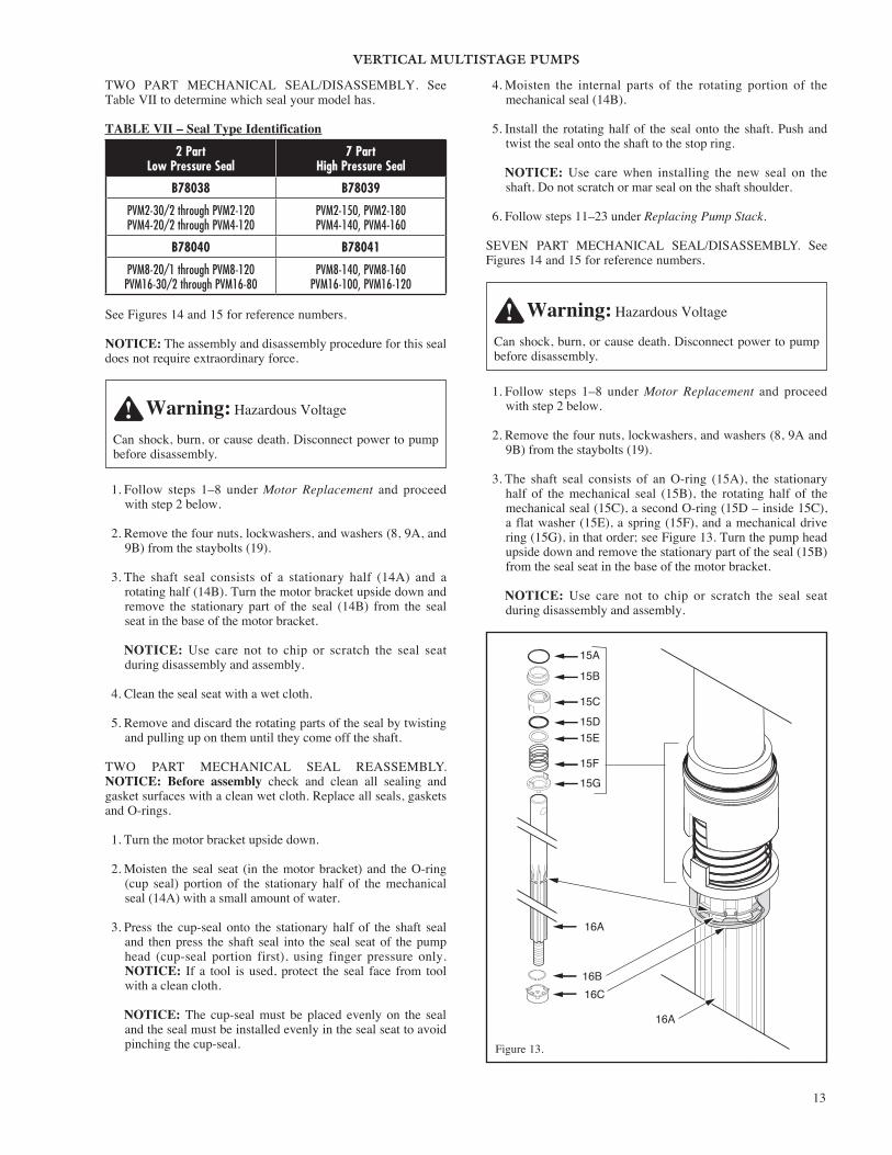
3. The shaft seal consists of an O-ring (15A), the stationary half of the mechanical seal (15B), the rotating half of the mechanical seal (15C), a second O-ring (15D – inside 15C), a flat washer (15E), a spring (15F), and a mechanical drive ring (15G), in that order; see Figure 13. Turn the pump head upside down and remove the stationary part of the seal (15B) from the seal seat in the base of the motor bracket.
NOTICE: Use care not to chip or scratch the seal seat during disassembly and assembly.
Warning: Hazardous Voltage
Can shock, burn, or cause death. Disconnect power to pump before disassembly.
Warning: Hazardous Voltage
Can shock, burn, or cause death. Disconnect power to pump before disassembly.
15A
15B
15C
15D15E
15F15G
16A
16B16C
16A
Figure 13.

VERTICAL MULTISTAGE PUMPS
14
4. Clean the seal seat with a wet cloth.
5. Remove the rotating parts of the seal by twisting and pulling up on them until they come off the shaft (15C and 15D, 15E, 15F, and 15G). Discard the old seal.
SEVEN PART MECHANICAL SEAL REASSEMBLY. NOTICE: Before assembly check and clean all sealing and gasket surfaces with a clean wet cloth. Replace all seals, gaskets and O-rings.
1. Turn the motor bracket (7) upside down.
2. Moisten the seal seat (in the motor bracket) with a small amount of water.
3. Lubricate the larger diameter O-ring (15A) with a small amount of water and install it on the stationary half of mechanical seal (15B).
4. Press the stationary half of the shaft seal (15B) with O-ring (15A and 15B) into the seal seat of the motor bracket. Use finger pressure only. If a tool is used, protect the seal face from tools with a clean cloth.
NOTICE: Be sure the seal is installed evenly to avoid pinching the O-ring.
5. Lubricate smaller diameter O-ring (15D) with water and press it into the rotating half of the mechanical seal (15C).
6. Install the mechanical drive ring (15G) on the shaft (16A). Be sure the drive ring butts up against the mechanical seal spacer (16C).
7. Install the spring (15F) up against the drive ring on the shaft.
8. Install the flatwasher (15E) on the shaft, against the spring.
9. Install the rotating half of the mechanical seal (15C) on the shaft. Align the grooves on the rotating half of the mechanical seal with the teeth on the mechanical drive ring (15G).
10. Follow steps 11–23 under Replacing Pump Stack.
FREQUENCY OF STARTS AND STOPS. Check pump cycling frequency and make sure that the pump is not starting more than:
TABLE IX – Maximum Number of Cycles
Cycles Motor HP Rating
20 times per hour 1/2 – 5 HP motors
15 times per hour 7- 1/2 – 15 HP motors
10 times per hour 20 and 25 HP motors
FROST PROTECTION.
1. If you do not use your pump during seasons of frost, drain it and add a glycol based antifreeze (50/50 mixture) to avoid damage.
2. Upon restart dispose of spent antifreeze properly.
3. Do not replace the drain plug or tighten the priming plug until you put the pump back in service again.
REGULAR MAINTENANCE CHECKS. The following checks should be made at regular intervals:
1. The pump meets required performance and is operating smoothly and quietly.
2. There are no leaks.
3. The motor is not overheating.
4. Remove and clean all strainers and filters in the system.
5. Verify amp draw – check motor amperage.
6. Pump wear rings and shaft require no regular maintenance.
TABLE VIII – Torque Specifications (foot-lbs.) For Cast Iron and Stainless Steel Models
Pump Model Number
Coupling Motor Staybolt Stack Nut
Socket Head Screw Hex Head Capscrew Hex Nut Hex Nut
M6 x 20 M8 x 25 M10 x 25 3/8 x 1-1/2
1/2 x 1-1/2 1/2 - 13 5/8 - 11 M8 M12
PVM2 Series 15 20 – 30 35 40 – 10 –
PVM4 Series 15 20 – 30 35 40 – 10 –
PVM8 Series 15 20 45 30 35 – 45 – 30
PVM16 Series – 20 45 – 35 – 45 – 30
Caution: Risk of Water Damage and Injury
Watch the direction of the priming plug and make sure that liquid escaping from it does not injure persons nearby or damage the motor or other components. In hot water installations, pay particular attention to the risk of injury from scalding hot water.
VERTICAL MULTISTAGE PUMPS
15
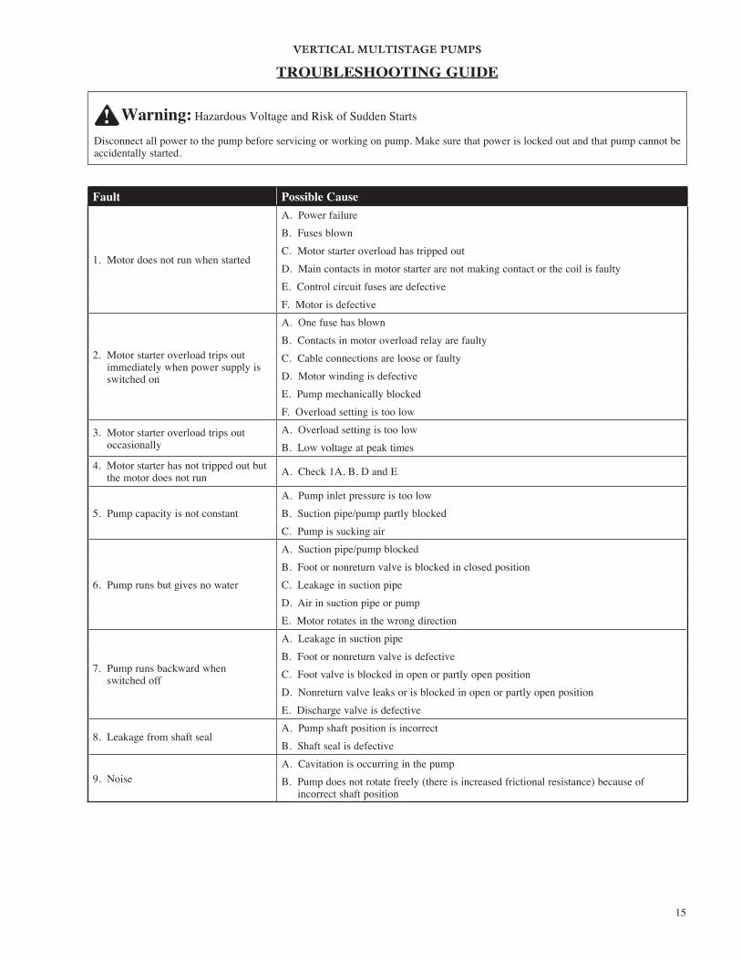
Fault Possible Cause
1. Motor does not run when started
A. Power failureB. Fuses blownC. Motor starter overload has tripped outD. Main contacts in motor starter are not making contact or the coil is faultyE. Control circuit fuses are defectiveF. Motor is defective
2. Motor starter overload trips out immediately when power supply is switched on
A. One fuse has blownB. Contacts in motor overload relay are faultyC. Cable connections are loose or faultyD. Motor winding is defectiveE. Pump mechanically blockedF. Overload setting is too low
3. Motor starter overload trips out occasionally
A. Overload setting is too lowB. Low voltage at peak times
4. Motor starter has not tripped out but the motor does not run A. Check 1A, B, D and E
5. Pump capacity is not constantA. Pump inlet pressure is too lowB. Suction pipe/pump partly blocked C. Pump is sucking air
6. Pump runs but gives no water
A. Suction pipe/pump blockedB. Foot or nonreturn valve is blocked in closed positionC. Leakage in suction pipeD. Air in suction pipe or pumpE. Motor rotates in the wrong direction
7. Pump runs backward when switched off
A. Leakage in suction pipeB. Foot or nonreturn valve is defectiveC. Foot valve is blocked in open or partly open positionD. Nonreturn valve leaks or is blocked in open or partly open positionE. Discharge valve is defective
8. Leakage from shaft sealA. Pump shaft position is incorrectB. Shaft seal is defective
9. NoiseA. Cavitation is occurring in the pumpB. Pump does not rotate freely (there is increased frictional resistance) because of
incorrect shaft position
TROUBLESHOOTING GUIDE
Warning: Hazardous Voltage and Risk of Sudden Starts
Disconnect all power to the pump before servicing or working on pump. Make sure that power is locked out and that pump cannot be accidentally started.
VERTICAL MULTISTAGE PUMPS
16
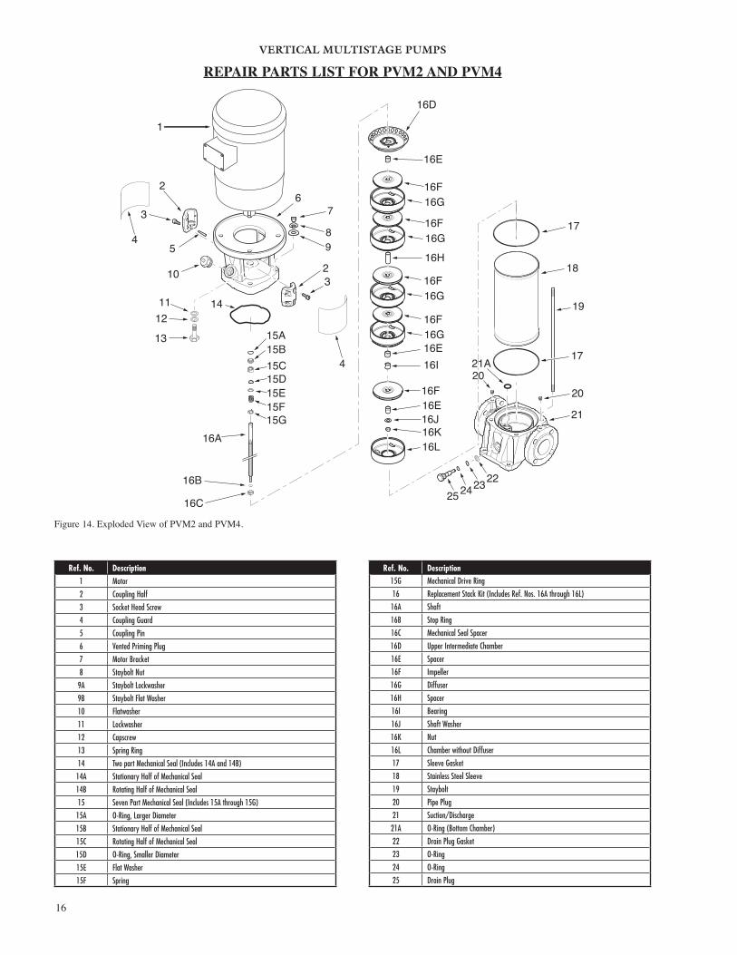
Figure 14. Exploded View of PVM2 and PVM4.
REPAIR PARTS LIST FOR PVM2 AND PVM4
2
5
6
15A15B15C15D15E15F15G
16A
16B
32
3
4
4
11
10
12
13
14
16C
16D
16E
16F16G
16F16G
16F16G
16F
16F
16G
18
19
1721A20
20
21
17
16H
16E16I
16E 16J
16L16K
7
89
22232425
1
Ref. No. Description1 Motor
2 Coupling Half
3 Socket Head Screw
4 Coupling Guard
5 Coupling Pin
6 Vented Priming Plug
7 Motor Bracket
8 Staybolt Nut
9A Staybolt Lockwasher
9B Staybolt Flat Washer
10 Flatwasher
11 Lockwasher
12 Capscrew
13 Spring Ring
14 Two part Mechanical Seal (Includes 14A and 14B)
14A Stationary Half of Mechanical Seal
14B Rotating Half of Mechanical Seal
15 Seven Part Mechanical Seal (Includes 15A through 15G)
15A O-Ring, Larger Diameter
15B Stationary Half of Mechanical Seal
15C Rotating Half of Mechanical Seal
15D O-Ring, Smaller Diameter
15E Flat Washer
15F Spring
Ref. No. Description15G Mechanical Drive Ring
16 Replacement Stack Kit (Includes Ref. Nos. 16A through 16L)
16A Shaft
16B Stop Ring
16C Mechanical Seal Spacer
16D Upper Intermediate Chamber
16E Spacer
16F Impeller
16G Diffuser
16H Spacer
16I Bearing
16J Shaft Washer
16K Nut
16L Chamber without Diffuser
17 Sleeve Gasket
18 Stainless Steel Sleeve
19 Staybolt
20 Pipe Plug
21 Suction/Discharge
21A O-Ring (Bottom Chamber)
22 Drain Plug Gasket
23 O-Ring
24 O-Ring
25 Drain Plug
VERTICAL MULTISTAGE PUMPS
17
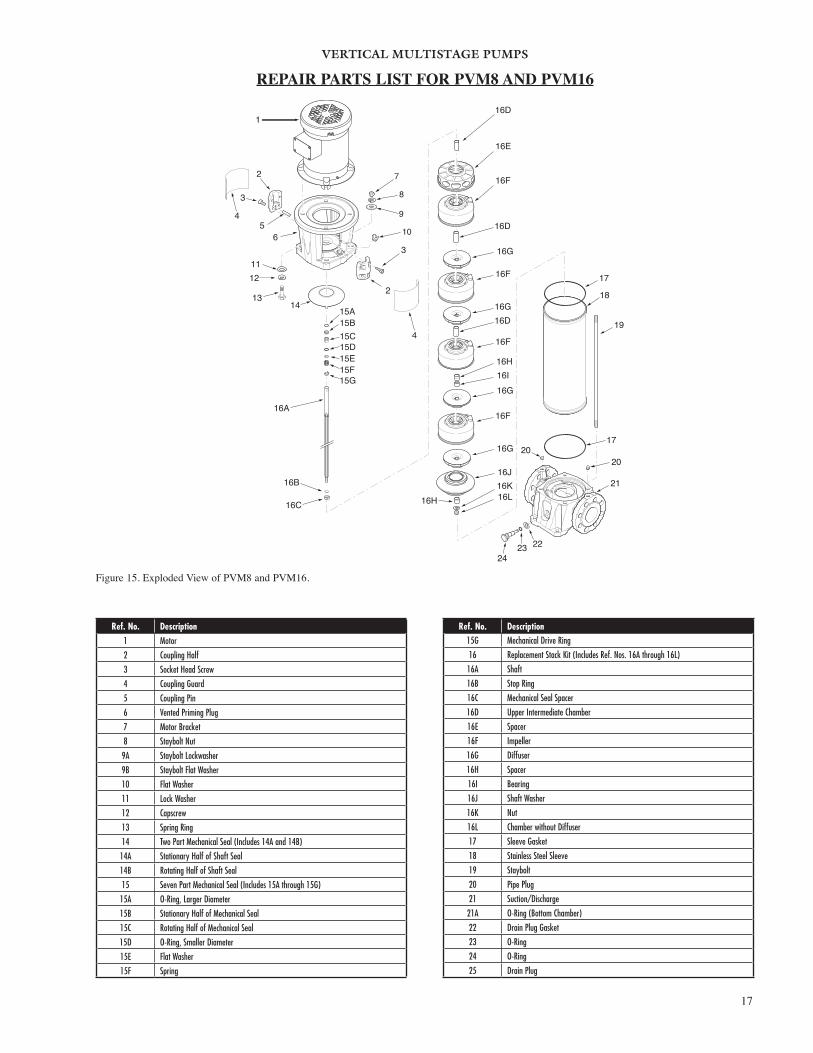
Figure 15. Exploded View of PVM8 and PVM16.
REPAIR PARTS LIST FOR PVM8 AND PVM16
1
2
3
56
13
1112
142
3
16A
16B
16C
16D
16D
16D
16E
16F
16F
16F
16F
16H
16H
16J16K16L
17
19
21
2020
17
18
16I
16G
16G
16G
16G
7
8
9
10
222324
15A15B15C15D15E15F15G
4
4
Ref. No. Description1 Motor
2 Coupling Half
3 Socket Head Screw
4 Coupling Guard
5 Coupling Pin
6 Vented Priming Plug
7 Motor Bracket
8 Staybolt Nut
9A Staybolt Lockwasher
9B Staybolt Flat Washer
10 Flat Washer
11 Lock Washer
12 Capscrew
13 Spring Ring
14 Two Part Mechanical Seal (Includes 14A and 14B)
14A Stationary Half of Shaft Seal
14B Rotating Half of Shaft Seal
15 Seven Part Mechanical Seal (Includes 15A through 15G)
15A O-Ring, Larger Diameter
15B Stationary Half of Mechanical Seal
15C Rotating Half of Mechanical Seal
15D O-Ring, Smaller Diameter
15E Flat Washer
15F Spring
Ref. No. Description15G Mechanical Drive Ring
16 Replacement Stack Kit (Includes Ref. Nos. 16A through 16L)
16A Shaft
16B Stop Ring
16C Mechanical Seal Spacer
16D Upper Intermediate Chamber
16E Spacer
16F Impeller
16G Diffuser
16H Spacer
16I Bearing
16J Shaft Washer
16K Nut
16L Chamber without Diffuser
17 Sleeve Gasket
18 Stainless Steel Sleeve
19 Staybolt
20 Pipe Plug
21 Suction/Discharge
21A O-Ring (Bottom Chamber)
22 Drain Plug Gasket
23 O-Ring
24 O-Ring
25 Drain Plug
VERTICAL MULTISTAGE PUMPS
18
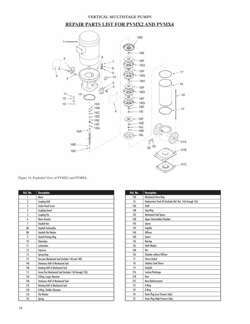
Figure 16. Exploded View of PVMX2 and PVMX4.
2
5 10
15A15B15C15D15E15F15G
16A
16B
32
3
4
4
1112
13
14
16C
16D
16E
16F16G
16F16G
16F16G
16F
16F
16G
18
19
17
21A
21C
17
16H
16E16I
16E 16J
16L16K
67
89
1
2223 21B
Ref. No. Description1 Motor
2 Coupling Half
3 Socket Head Screw
4 Coupling Guard
5 Coupling Pin
6 Motor Bracket
7 Staybolt Nut
8A Staybolt Lockwasher
8B Staybolt Flat Washer
9 Vented Priming Plug
10 Flatwasher
11 Lockwasher
12 Capscrew
13 Spring Ring
14 Two part Mechanical Seal (Includes 14A and 14B)
14A Stationary Half of Mechanical Seal
14B Rotating Half of Mechanical Seal
15 Seven Part Mechanical Seal (Includes 15A through 15G)
15A O-Ring, Larger Diameter
15B Stationary Half of Mechanical Seal
15C Rotating Half of Mechanical Seal
15D O-Ring, Smaller Diameter
15E Flat Washer
15F Spring
Ref. No. Description15G Mechanical Drive Ring
16 Replacement Stack Kit (Includes Ref. Nos. 16A through 16L)
16A Shaft
16B Stop Ring
16C Mechanical Seal Spacer
16D Upper Intermediate Chamber
16E Spacer
16F Impeller
16G Diffuser
16H Spacer
16I Bearing
16J Shaft Washer
16K Nut
16L Chamber without Diffuser
17 Sleeve Gasket
18 Stainless Steel Sleeve
19 Staybolt
21A Suction/Discharge
21B Base
21C Base Reinforcement
22 O-Ring
23 O-Ring
24 Drain Plug (Low Pressure Side)
25 Drain Plug (High Pressure Side)
REPAIR PARTS LIST FOR PVMX2 AND PVMX4

VERTICAL MULTISTAGE PUMPS
19
Figure 17. Exploded View of PVMX8 and PVMX16.
1
2
3
5
7
13
1112
14
2
3
16A
16B
16C
16D
16D
16D
16E
16F
16F
16F
16F
16H
16H
16J16K16L
17
19
21A
17
18
16I
16G
16G
16G
16G
8
9
10
6
4
4
21B2223
22 23
15B15C15D15E15F15G
Ref. No. Description1 Motor
2 Coupling Half
3 Socket Head Screw
4 Coupling Guard
5 Coupling Pin
6 Vented Priming Plug
7 Motor Bracket
8 Staybolt Nut
9A Staybolt Lockwasher
9B Staybolt Flat Washer
10 Flat Washer
11 Lock Washer
12 Capscrew
13 Spring Ring
14 Two Part Mechanical Seal (Includes 14A and 14B)
14A Stationary Half of Shaft Seal
14B Rotating Half of Shaft Seal
15 Seven Part Mechanical Seal (Includes 15A through 15G)
15A O-Ring, Larger Diameter
15B Stationary Half of Mechanical Seal
15C Rotating Half of Mechanical Seal
15D O-Ring, Smaller Diameter
15E Flat Washer
15F Spring
Ref. No. Description15G Mechanical Drive Ring
16 Replacement Stack Kit (Includes Ref. Nos. 16A through 16L)
16A Shaft
16B Stop Ring
16C Mechanical Seal Spacer
16D Spacer
16E Top Diffuser
16F Diffuser
16G Impeller
16H Spacer
16I Bearing
16J Suction Interconnector
16K Washer
16L Lock Nut
17 Sleeve Gasket
18 Stainless Steel Sleeve
19 Staybolt
21A Suction/Discharge
21B Base
22 O-Ring
23 O-Ring
24 Drain Plug (Low Pressure Side)
25 Drain Plug (High Pressure Side)
REPAIR PARTS LIST FOR PVMX8 AND PVMX16

WARRANTYSeller warrants equipment (and its component parts) of its own manufacture against defects in materials and workmanship under normal use and service for one (1) year from the date of installation or start-up, or for eighteen (18) months after the date of shipment, whichever occurs first. Seller does not warrant accessories or components that are not manufactured by Seller; however, to the extent possible, Seller agrees to assign to Buyer its rights under the original manufacturer's warranty, without recourse to Seller. Buyer must give Seller notice in writing of any alleged defect covered by this warranty (together with all identifying details, including the serial number, the type of equipment, and the date of purchase) within thirty (30) days of the discovery of such defect during the warranty period. No claim made more than 30 days after the expiration of the warranty period shall be valid. Guarantees of performance and warranties are based on the use of original equipment manufactured (OEM) replacement parts. Seller assumes no responsibility or liability if alterations, non-authorized design modifications and/or non-OEM replacement parts are incorporated If requested by Seller, any equipment (or its component parts) must be promptly returned to Seller prior to any attempted repair, or sent to an authorized service station designated by Seller, and Buyer shall prepay all shipping expenses. Seller shall not be liable for any loss or damage to goods in transit, nor will any warranty claim be valid unless the returned goods are received intact and undamaged as a result of shipment. Repaired or replaced material returned to customer will be shipped F.O.B., Seller's factory. Seller will not give Buyer credit for parts or equipment returned to Seller, and will not accept delivery of any such parts or equipment, unless Buyer has obtained Seller's approval in writing. The warranty extends to repaired or replaced parts of Seller's manufacture for ninety (90) days or for the remainder of the original warranty period applicable to the equipment or parts being repaired or replaced, whichever is greater. This warranty applies to the repaired or replaced part and is not extended to the product or any other component of the product being repaired. Repair parts of its own manufacture sold after the original warranty period are warranted for a period of one (1) year from shipment against defects in materials and workmanship under normal use and service. This warranty applies to the replacement part only and is not extended to the product or any other component of the product being repaired. Seller may substitute new equipment or improve part(s) of any equipment judged defective without further liability. All repairs or services performed by Seller, which are not covered by this warranty, will be charged in accordance with Seller's standard prices then in effect.
THIS WARRANTY IS THE SOLE WARRANTY OF SELLER AND SELLER HEREBY EXPRESSLY DISCLAIMS AND BUYER WAIVES ALL OTHER WARRANTIES EXPRESSED, IMPLIED IN LAW OR IMPLIED IN FACT, INCLUDING ANY WARRANTIES OF MERCHANTABILITY OR FITNESS FOR A PARTICULAR PURPOSE. Seller's sole obligation under this warranty shall be, at its option, to repair or replace any equipment (or its component parts) which has a defect covered by this warranty, or to refund the purchase price of such equipment or part. Under the terms of this warranty, Seller shall not be liable for (a) consequential, collateral, special or liquidated losses or damages; (b) equipment conditions caused by normal wear and tear, abnormal conditions of use, accident, neglect, or misuse of said equipment; (c) the expense of, and loss or damage caused by, repairs or alterations made by anyone other than the Seller; (d) damage caused by abrasive materials, chemicals, scale deposits, corrosion, lightning, improper voltage, mishandling, or other similar conditions; (e) any loss, damage, or expense relating to or resulting from installation, removal or reinstallation of equipment; (f) any labor costs or charges incurred in repairing or replacing defective equipment or parts, including the cost of reinstalling parts that are repaired or replaced by Seller; (g) any expense of shipment of equipment or repaired or replacement parts; or (h) any other loss, damage or expense of any nature.
The above warranty shall not apply to any equipment which may be separately covered by any alternate or special warranties.
PERFORMANCE: In the absence of Certified Pump Performance Tests, equipment performance is not warranted or guaranteed. Performance curves and other information submitted to Buyer are approximate and no warranty or guarantee shall be deemed to arise as a result of such submittal. All testing shall be done in accordance with Seller's standard policy under Hydraulic Institute procedures.
LIABILITY LIMITATIONS: Under no circumstances shall the Seller have any liability under the Order or otherwise for liquidated damages or for collateral, consequential or special damages or for loss of profits, or for actual losses or for loss of production or progress of construction, regardless of the cause of such damages or losses. In any event, Seller's aggregate total liability under the Order or otherwise shall not exceed the contract price.
ACTS OF GOD: Seller shall in no event be liable for delays in delivery of the equipment or other failures to perform caused by fires, acts of God, strikes, labor difficulties, acts of governmental or military authorities, delays in transportation or procuring materials, or causes of any kind beyond Seller's control.
COMPLIANCE WITH LAW: Seller agrees to comply with all United States laws and regulations applicable to the manufacturing of the subject equipment. Such compliance shall include: The Fair Labor Standards Acts of 1938, as amended; Equal Employment Opportunity clauses of Executive Order 11246, as amended; Occupational Safety and Health Act of 1970 and the standards promulgated thereunder, if applicable. Since compliance with the various Federal, State, and Local laws and regulations concerning occupational health and safety, pollution or local codes are affected by the use, installation and operation of the equipment and other matters over which Seller has no control, Seller assumes no responsibility for compliance with those laws and regulations, whether by way of indemnity, warranty, or otherwise. It is incumbent upon the Buyer to specify equipment which complies with local codes and ordinances.
800 Airport RoadNorth Aurora, Illinois 60542630-859-7000www.aurorapump.com