Embed Size (px)
DESCRIPTION
ModBus Register Mapping Centrainverter for APP Powerone Solar Inverter
Citation preview

P1 AURORA CENTRAL RTU Modbus Specification. (3I56001F000G) (Related Firmware Version C012) March 2012, Version 1. Rev 13
This document is confidential to the organisation receiving it. Neither the document nor the information contained in it may be revealed to any third parties without an approval from P1’s executive management P1 reserves the right to change any information in this specification without advise
By Power One Italy Page of 27 2
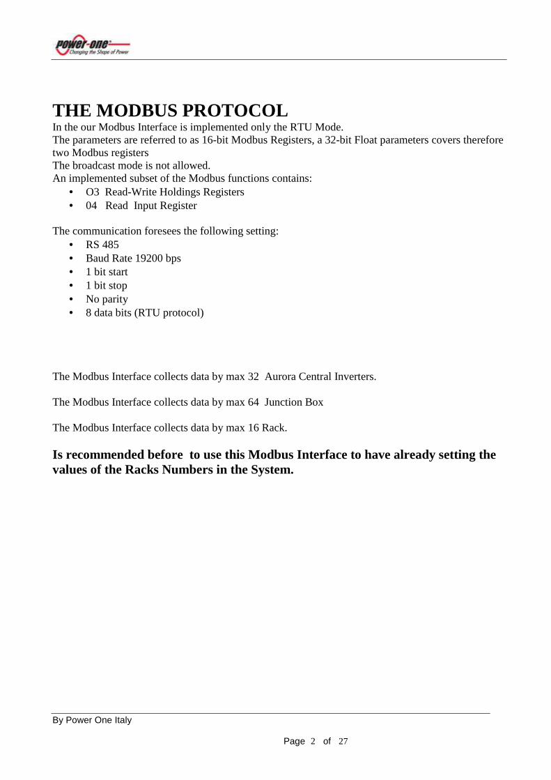
THE MODBUS PROTOCOL In the our Modbus Interface is implemented only the RTU Mode. The parameters are referred to as 16-bit Modbus Registers, a 32-bit Float parameters covers therefore two Modbus registers The broadcast mode is not allowed. An implemented subset of the Modbus functions contains:
• O3 Read-Write Holdings Registers • 04 Read Input Register
The communication foresees the following setting:
• RS 485 • Baud Rate 19200 bps • 1 bit start • 1 bit stop • No parity • 8 data bits (RTU protocol)
The Modbus Interface collects data by max 32 Aurora Central Inverters. The Modbus Interface collects data by max 64 Junction Box The Modbus Interface collects data by max 16 Rack. Is recommended before to use this Modbus Interface to have already setting the values of the Racks Numbers in the System.

By Power One Italy Page of 27 3
READ OUTPUTS REGISTERS (Rd 03/Wr 06-16)
This function allows to require the value of 16-bit register containing Modbus Address parameter. This function allows also to change this parameter via command 06 , the value changed is saved in EEprom memory. The Default parameter is 0x01
Register Map.
Add. Word Description Unit Format 0001 1 Modbus Address Decimal (1-247) Unsigned int
This function allows to synchronize Modbus collection Data .(Junction Box and Rack) Is recommended to use this feature every day at the start of the system to synchronize the data acquired. The parameters accepted are: 1 = Synchronization. This register show also the answers at the Modbus Synchronization command 9999 = Synchronization Pending.
Register Map.
Add. Word Description Unit Format 0002 1 Modbus Synchronization Decimal
Unsigned int

By Power One Italy Page of 27 4
This function allows to setting the parameter :Message Time to Live. (The maximum number of lost messages in succession before you have a situation of LOST COMUNICATION) The parameters accepted are: Min .= 5 Max. = 20 Default = 5 (See Note3)
Register Map.
Add. Word Description Unit Format 0010 1 Modbus Message Time to Live Decimal
Unsigned int
This function allows to setting the parameter : State of the data collection. The parameters accepted are: 1 = asks for global measurements (only for a Master, registers xx84 to xx94 ). 0 = asks for module measurements (only for a Slave, registers xx48 to xx60). Default = 1 (See Note 2 & 3)
Register Map.
Add. Word Description Unit Format 0011 1 Modbus state of the data
collection Decimal
Unsigned int
This function allows to setting the reset of the values in the Modbus table, when happens a situation of LOST COMUNICATION. The parameters accepted are: 1 = Values cleared. 0 = Values no cleared. Default = 1 (See Note3)
Register Map.
Add. Word Description Unit Format 0012 1 Modbus resets the own values
after a LOST COMUNICATION Decimal
Unsigned int

By Power One Italy Page of 27 5
This function allows to setting the rate of sending for messages to Inverter Module The parameters accepted are: Min .= 50 (ms) Max. = 250 (ms) Default = 250 (ms) (See Note3)
Register Map.
Add. Word Description Unit Format 0013 1 Modbus Speed messages to the
Inverter Modules Decimal
Unsigned int
This function allows to setting the rate of sending for messages to Junction Box Module The parameters accepted are: Min .= 150 (ms) Max. = 250 (ms) Default = 250 (ms)
Register Map.
Add. Word Description Unit Format 0014 1 Modbus Speed messages to the
Junction Box Modules Decimal
Unsigned int

By Power One Italy Page of 27 6
This function allows to require the value of 16-bit register containing the number of the Rack presents in the system and the Rack Number associate. This function allows also to have a Remote ON OFF in a Rack, starting from register 117 until register 132. The parameter is : 0 for ON 1 for OFF This register show also the answers at the On-Off command 0= Command ON OK 1= Command OFF OK 3 = Communication Lost 4 = Rack not present The Default value for this registers is 0
Register Map.
Add. Word Description Unit Format 0100 1 Numbers Racks presents in the
System Decimal
(Read Only) Unsigned Int
0101 1 1st Rack Number found in the System
Decimal (Read Only)
Unsigned Int
…. …. …. …. …. 0116 1 16th Rack Number found in the
System Decimal
(Read Only) Unsigned Int
…. …. …. …. …. 0117 1 Remote On-Off for 1st Rack
Number found in the System Decimal (0 = ON) (1=OFF)
Unsigned Int
…. …. …. …. …. 0132 1 Remote On-Off for 16th Rack
Number found in the System Decimal (0 = ON) (1=OFF)
Unsigned Int
By Power One Italy Page of 27 7
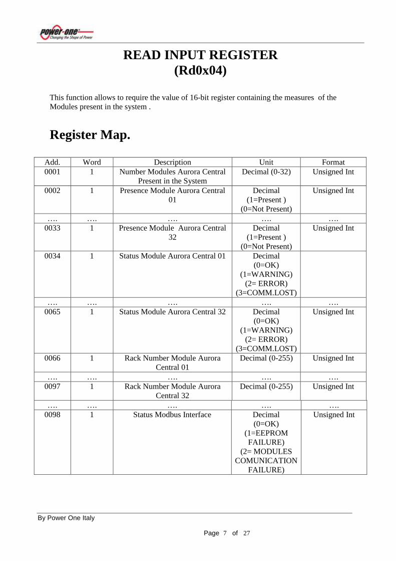
READ INPUT REGISTER (Rd0x04)
This function allows to require the value of 16-bit register containing the measures of the Modules present in the system . Register Map.
Add. Word Description Unit Format 0001 1 Number Modules Aurora Central
Present in the System Decimal (0-32) Unsigned Int
0002 1 Presence Module Aurora Central 01
Decimal (1=Present )
(0=Not Present)
Unsigned Int
…. …. …. …. …. 0033 1 Presence Module Aurora Central
32 Decimal
(1=Present ) (0=Not Present)
Unsigned Int
0034 1 Status Module Aurora Central 01 Decimal (0=OK)
(1=WARNING) (2= ERROR)
(3=COMM.LOST)
…. …. …. …. …. 0065 1 Status Module Aurora Central 32 Decimal
(0=OK) (1=WARNING)
(2= ERROR) (3=COMM.LOST)
Unsigned Int
0066 1 Rack Number Module Aurora Central 01
Decimal (0-255) Unsigned Int
…. …. …. …. …. 0097 1 Rack Number Module Aurora
Central 32 Decimal (0-255) Unsigned Int
…. …. …. …. …. 0098 1 Status Modbus Interface Decimal
(0=OK) (1=EEPROM FAILURE)
(2= MODULES COMUNICATION
FAILURE)
Unsigned Int

By Power One Italy Page of 27 8
Add. Word Description Unit Format 0100 1 Measures Module Aurora Central
01 View Reg.Map
Module 01 Unsigned Int
…. …. …. …. …. 0134 1 Measures Module Aurora Central
01 View Reg.Map
Module 01 Unsigned Int
0136 2 Measures Module Aurora Central 01
View Reg.Map Module 01
Float
0138 2 Measures Module Aurora Central 01
View Reg.Map Module 01
Float
…. …. …. …. …. 0194 2 Measures Module Aurora Central
01 View Reg.Map
Module 01 Float
…. …. …. …. ….
Add. Word Description Unit Format 3200 1 Measures Module Aurora Central
32 View Reg.Map
Module 01 Unsigned Int
…. …. …. …. …. 3234 1 Measures Module Aurora Central
32 View Reg.Map
Module 01 Unsigned Int
3236 2 Measures Module Aurora Central 32
View Reg.Map Module 01
Float
3238 2 Measures Module Aurora Central 32
View Reg.Map Module 01
Float
…. …. …. …. …. 3294 2 Measures Module Aurora Central
32 View Reg.Map
Module 01 Float

By Power One Italy Page of 27 9
This function allows requiring the value of 16-bit register containing the values concerning the type of equipment in the system.
. Register Map.
Add. Word Description Unit Format 3500 1 Aurora Type Module 01 Decimal (ASCII )
( See Table 1.1)
Unsigned Int
3501 1 Grid Type Module 01 Decimal (ASCII ) ( See Table 1.2)
Unsigned Int
3502 1 Trafo Type Module 01 Decimal (ASCII ) ( See Table 1.3)
Unsigned Int
3503 1 Wind Type Module 01 Decimal (ASCII ) ( See Table 1.4)
Unsigned Int
…. …. …. …. ….
Add. Word Description Unit Format 3624 1 Aurora Type Module 32 Decimal (ASCII )
( See Table 1.1)
Unsigned Int
3625 1 Grid Type Module 32 Decimal (ASCII ) ( See Table 1.2)
Unsigned Int
3626 1 Trafo Type Module 32 Decimal (ASCII ) ( See Table 1.3)
Unsigned Int
3627 1 Wind Type Module 32 Decimal (ASCII ) ( See Table 1.4)
Unsigned Int

By Power One Italy Page of 27 10
This function allows to require the value of 16-bit register containing the Firmware Revision Modbus Interface Register Map.
Add. Word Description Unit Format 3650 1 Modbus Interface Type Decimal (ASCII )
A=Aurora String C= AuroraCentral
Unsigned Int
3651 1 Firmware Major Release Decimal (ASCII )
Unsigned Int
3652 1 Firmware Minor Release Decimal (ASCII )
Unsigned Int
3653 1 Firmware Build Release Decimal (ASCII )
Unsigned Int
This function allows to require the value of 16-bit register containing the collection of Energy Modules Register Map.
Add. Word Description Unit Format 3700 2 Collection Daily Energy of all
Modules KWattHour IEEE 32 Float
3702 2 Collection Total Energy of all Modules
KWattHour IEEE 32 Float
3704 2 Collection Partial Energy of all Modules
KWattHour IEEE 32 Float
3706 2 Collection Week Energy of all Modules
KWattHour IEEE 32 Float
3708 2 Collection Monthly Energy of all Modules
KWattHour IEEE 32 Float
3710 2 Collection Yearly Energy of all Modules
KWattHour IEEE 32 Float
By Power One Italy Page of 27 11
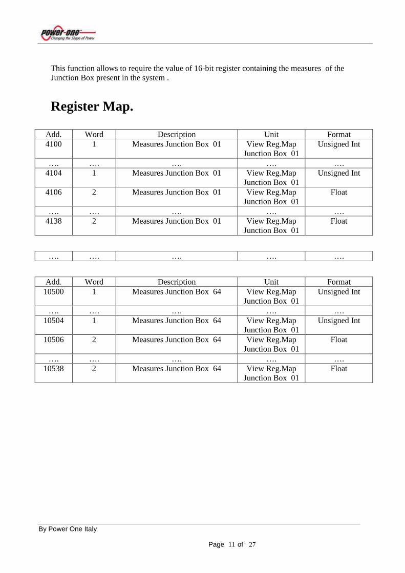
This function allows to require the value of 16-bit register containing the measures of the Junction Box present in the system . Register Map.
Add. Word Description Unit Format 4100 1 Measures Junction Box 01 View Reg.Map
Junction Box 01 Unsigned Int
…. …. …. …. …. 4104 1 Measures Junction Box 01 View Reg.Map
Junction Box 01 Unsigned Int
4106 2 Measures Junction Box 01 View Reg.Map Junction Box 01
Float
…. …. …. …. …. 4138 2 Measures Junction Box 01 View Reg.Map
Junction Box 01 Float
…. …. …. …. ….
Add. Word Description Unit Format 10500 1 Measures Junction Box 64 View Reg.Map
Junction Box 01 Unsigned Int
…. …. …. …. …. 10504 1 Measures Junction Box 64 View Reg.Map
Junction Box 01 Unsigned Int
10506 2 Measures Junction Box 64 View Reg.Map Junction Box 01
Float
…. …. …. …. …. 10538 2 Measures Junction Box 64 View Reg.Map
Junction Box 01 Float

By Power One Italy Page of 27 12
Register Map. Module 01. The below register map is referred at the Module 01 , but it is valid for all the Modules presents in the system Aurora Central.
Add. Word Description Unit Format 0100 1 Step Decimal (TBD) Unsigned Int 0101 1 RackNumber Module 01 Decimal (0-255) Unsigned Int 0102 1 JBManaged Decimal
(0-12) Number J.B.
presents in the system
Unsigned Int
0103 1 JBMaster Decimal (1= JB Master)
(0= JB Not Master)
Unsigned Int
0104 1 JA_High (Junction Box address)
Decimal ( See Table 3)
Unsigned Int
0105 1 JA_Low (Junction Box address)
Decimal ( See Table 3)
Unsigned Int
0106 1 Rack SN0 Module 01 Decimal (ASCII ) (See Note1)
Unsigned Int
…. …. …. …. …. 0111 1 Rack SN5 Module 01 Decimal (ASCII )
(See Note1) Unsigned Int
0112 1 Rack PN 0 Module 01 Decimal (ASCII ) (See Note1)
Unsigned Int
…. …. …. …. …. 0117 1 Rack PN5 Module 01 Decimal (ASCII )
(See Note1) Unsigned Int
0118 1 SN0 Module 01 Decimal (ASCII ) (See Note1)
Unsigned Int
…. …. …. …. …. 0123 1 SN5 Module 01 Decimal (ASCII )
(See Note1) Unsigned Int
0124 1 PN0 Module 01 Decimal (ASCII ) (See Note1)
Unsigned Int
…. …. …. …. ….
By Power One Italy Page of 27 13
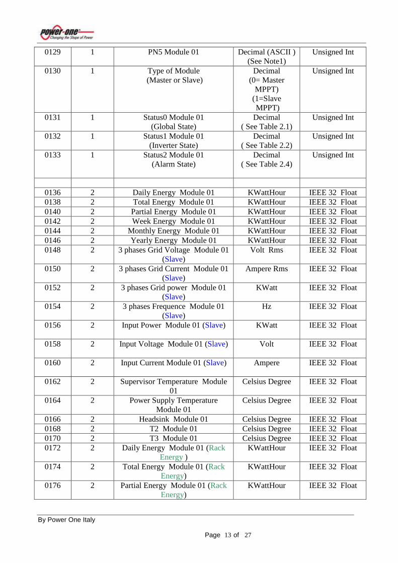
0129 1 PN5 Module 01 Decimal (ASCII ) (See Note1)
Unsigned Int
0130 1 Type of Module (Master or Slave)
Decimal (0= Master
MPPT) (1=Slave MPPT)
Unsigned Int
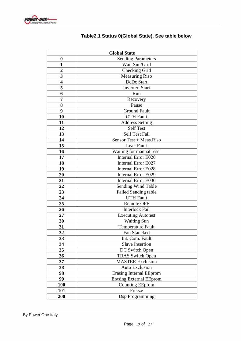
0131 1 Status0 Module 01 (Global State)
Decimal ( See Table 2.1)
Unsigned Int
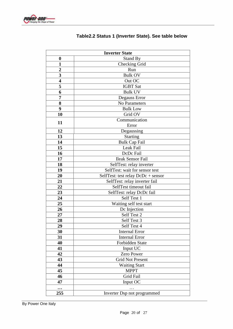
0132 1 Status1 Module 01 (Inverter State)
Decimal ( See Table 2.2)
Unsigned Int
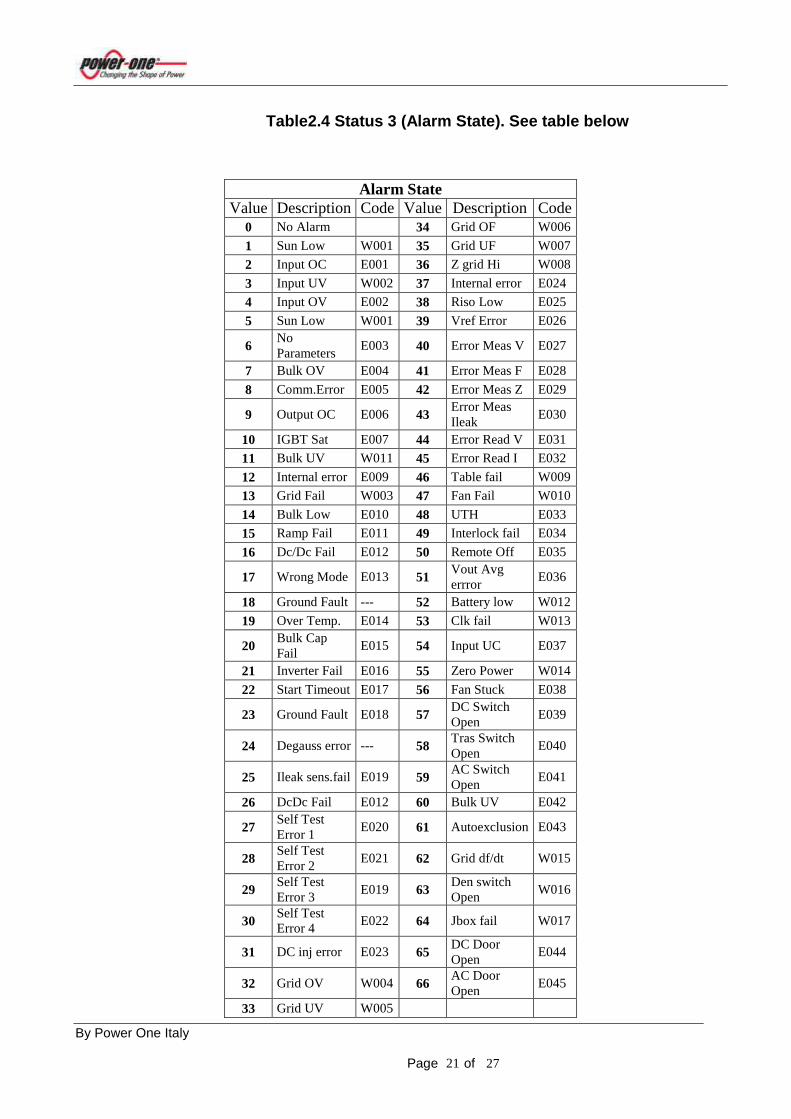
0133 1 Status2 Module 01 (Alarm State)
Decimal ( See Table 2.4)
Unsigned Int
0136 2 Daily Energy Module 01 KWattHour IEEE 32 Float 0138 2 Total Energy Module 01 KWattHour IEEE 32 Float 0140 2 Partial Energy Module 01 KWattHour IEEE 32 Float 0142 2 Week Energy Module 01 KWattHour IEEE 32 Float 0144 2 Monthly Energy Module 01 KWattHour IEEE 32 Float 0146 2 Yearly Energy Module 01 KWattHour IEEE 32 Float 0148 2 3 phases Grid Voltage Module 01
(Slave) Volt Rms
IEEE 32 Float
0150 2 3 phases Grid Current Module 01 (Slave)
Ampere Rms
IEEE 32 Float
0152 2 3 phases Grid power Module 01 (Slave)
KWatt
IEEE 32 Float
0154 2 3 phases Frequence Module 01 (Slave)
Hz
IEEE 32 Float
0156 2 Input Power Module 01 (Slave) KWatt
IEEE 32 Float
0158 2 Input Voltage Module 01 (Slave) Volt
IEEE 32 Float
0160 2 Input Current Module 01 (Slave) Ampere
IEEE 32 Float
0162 2 Supervisor Temperature Module 01
Celsius Degree IEEE 32 Float
0164 2 Power Supply Temperature Module 01
Celsius Degree IEEE 32 Float
0166 2 Headsink Module 01 Celsius Degree IEEE 32 Float 0168 2 T2 Module 01 Celsius Degree IEEE 32 Float 0170 2 T3 Module 01 Celsius Degree IEEE 32 Float 0172 2 Daily Energy Module 01 (Rack
Energy ) KWattHour IEEE 32 Float
0174 2 Total Energy Module 01 (Rack Energy)
KWattHour IEEE 32 Float
0176 2 Partial Energy Module 01 (Rack Energy)
KWattHour IEEE 32 Float

By Power One Italy Page of 27 14
0178 2 Week Energy Module 01 (Rack
Energy) KWattHour IEEE 32 Float
0180 2 Monthly Energy Module 01 (Rack Energy)
KWattHour IEEE 32 Float
0182 2 Yearly Energy Module 01 (Rack Energy)
KWattHour IEEE 32 Float
0184 2 Grid Voltage Module 01 (Master Mean of 3 phases
Global Measurements)
Volt
IEEE 32 Float
0186 2 Grid Current Module 01 (Master Mean of 3 phases
Global Measurements)
Ampere
IEEE 32 Float
0188 2 Grid power Module 01 (Master Mean of 3 phases
Global Measurements)
KWatt
IEEE 32 Float
0190 2 Input Power Module 01 (Master Global Measurements)
KWatt
IEEE 32 Float
0192 2 Input Voltage Module 01 (Master Global Measurements)
Volt
IEEE 32 Float
0194 2 Input Current Module 01 (Master Global Measurements)
Ampere
IEEE 32 Float

By Power One Italy Page of 27 15
Register Map. Junction Box 01. The below register map is referred at the Junction Box 01 , but it is valid for all the Junction Box presents in the system Aurora Central.
Add. Word Description Unit Format 4100 1 Numbers Junction Box presents in
the System (Total) Decimal Unsigned Int
4101 1 RackNumber of the Module that manages the Junction Box
Decimal Unsigned Int
4102 1 Address of the Module that manages the Junction Box
Decimal
Unsigned Int
4103 1 Junction Box present in the Rack Decimal
Unsigned Int
4104 1 Address Junction Box 01 Decimal
Unsigned Int
4105 1 Fuses State 1 Decimal (See Table 4.1)
Unsigned Int
4106 1 Fuses State 2 Decimal (See Table 4.2)
Unsigned Int
4107 1 String Currents State 0 Decimal (See Table 4.3)
Unsigned Int
4108 1 String Currents State 1/ Fuses State 0
(See Table 4.3 by Current State 1
See Table 4.2 by Fuses State 0)
Unsigned Int
04109 1 JB State Decimal (See Table 4.1)
Unsigned Int
4110 1 Junction Box Type Decimal (ASCII ) 71 =3G90(Def.)
76 =3L11
Unsigned Int
4111 1 Junction Box Digital Input state Decimal (This register is valid only for 3L11 Type
See Table 5)
Unsigned Int

By Power One Italy Page of 27 16
4112 1 Junction Box Digital Input ID1
function Flag Decimal
(This register is valid only for 3L11 Type
0=Generic Alarm Input
1= DC Isolation Switch Reading )
Unsigned Int
4113 1 Junction Box Analog Input 2 Function Flag
Decimal (This register is valid only for 3L11 Type 0=Generic
Measure Input 1= PT100 Input)
Unsigned Int
…. …. …. …. …. 4116 2 Current I0 Junction Box 01 Ampere IEEE 32 Float 4118 2 Current I1 Junction Box 01 Ampere IEEE 32 Float 4120 2 Current I2 Junction Box 01 Ampere IEEE 32 Float 4122 2 Current I3 Junction Box 01 Ampere IEEE 32 Float 4124 2 Current I4 Junction Box 01 Ampere IEEE 32 Float 4126 2 Current I5 Junction Box 01 Ampere IEEE 32 Float 4128 2 Current I6 Junction Box 01 Ampere IEEE 32 Float 4130 2 Current I7 Junction Box 01 Ampere IEEE 32 Float 4132 2 Current I8 Junction Box 01 Ampere IEEE 32 Float 4134 2 Current I9 Junction Box 01 Ampere IEEE 32 Float 4136 2 Internal Temperature Junction
Box 01 Celsius Degree IEEE 32 Float
4138 2 Global Parallel Voltage Junction Box 01
Volt IEEE 32 Float
4140 2 Analog Input 1 Junction Box 01 TBD IEEE 32 Float 4142 2 Analog Input 2 Junction Box 01 TBD IEEE 32 Float 4144 2 Analog Input 3 Junction Box 01 TBD IEEE 32 Float 4146 2 Analog Input 4 Junction Box 01 TBD IEEE 32 Float 4148 2 Global String Current Junction
Box 01 Ampere IEEE 32 Float
By Power One Italy Page of 27 17
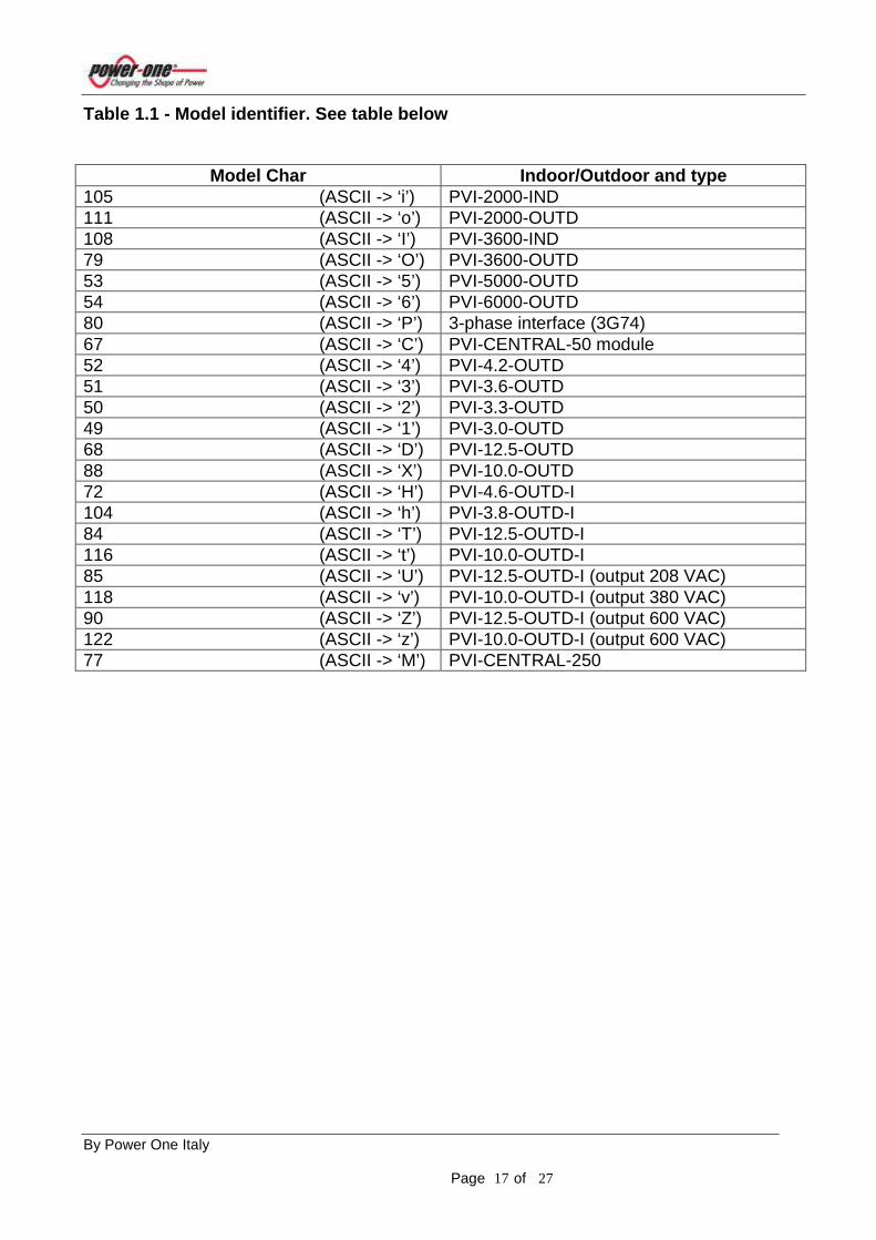
Table 1.1 - Model identifier. See table below
Model Char Indoor/Outdoor and type 105 (ASCII -> ‘i’) PVI-2000-IND 111 (ASCII -> ‘o’) PVI-2000-OUTD 108 (ASCII -> ‘I’) PVI-3600-IND 79 (ASCII -> ‘O’) PVI-3600-OUTD 53 (ASCII -> ‘5’) PVI-5000-OUTD 54 (ASCII -> ‘6’) PVI-6000-OUTD 80 (ASCII -> ‘P’) 3-phase interface (3G74) 67 (ASCII -> ‘C’) PVI-CENTRAL-50 module 52 (ASCII -> ‘4’) PVI-4.2-OUTD 51 (ASCII -> ‘3’) PVI-3.6-OUTD 50 (ASCII -> ‘2’) PVI-3.3-OUTD 49 (ASCII -> ‘1’) PVI-3.0-OUTD 68 (ASCII -> ‘D’) PVI-12.5-OUTD 88 (ASCII -> ‘X’) PVI-10.0-OUTD 72 (ASCII -> ‘H’) PVI-4.6-OUTD-I 104 (ASCII -> ‘h’) PVI-3.8-OUTD-I 84 (ASCII -> ‘T’) PVI-12.5-OUTD-I 116 (ASCII -> ‘t’) PVI-10.0-OUTD-I 85 (ASCII -> ‘U’) PVI-12.5-OUTD-I (output 208 VAC) 118 (ASCII -> ‘v’) PVI-10.0-OUTD-I (output 380 VAC) 90 (ASCII -> ‘Z’) PVI-12.5-OUTD-I (output 600 VAC) 122 (ASCII -> ‘z’) PVI-10.0-OUTD-I (output 600 VAC) 77 (ASCII -> ‘M’) PVI-CENTRAL-250
By Power One Italy Page of 27 18
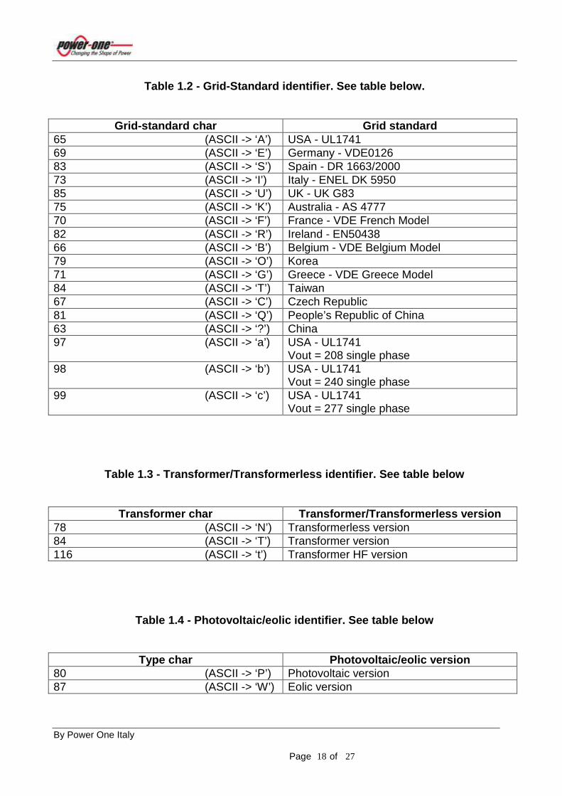
Table 1.2 - Grid-Standard identifier. See table bel ow.
Grid-standard char Grid standard 65 (ASCII -> ‘A’) USA - UL1741 69 (ASCII -> ‘E’) Germany - VDE0126 83 (ASCII -> ‘S’) Spain - DR 1663/2000 73 (ASCII -> ‘I’) Italy - ENEL DK 5950 85 (ASCII -> ‘U’) UK - UK G83 75 (ASCII -> ‘K’) Australia - AS 4777 70 (ASCII -> ‘F’) France - VDE French Model 82 (ASCII -> ‘R’) Ireland - EN50438 66 (ASCII -> ‘B’) Belgium - VDE Belgium Model 79 (ASCII -> ‘O’) Korea 71 (ASCII -> ‘G’) Greece - VDE Greece Model 84 (ASCII -> ‘T’) Taiwan 67 (ASCII -> ‘C’) Czech Republic 81 (ASCII -> ‘Q’) People’s Republic of China 63 (ASCII -> ‘?’) China 97 (ASCII -> ‘a’) USA - UL1741
Vout = 208 single phase 98 (ASCII -> ‘b’) USA - UL1741
Vout = 240 single phase 99 (ASCII -> ‘c’) USA - UL1741
Vout = 277 single phase
Table 1.3 - Transformer/Transformerless identifier. See table below
Transformer char Transformer/Transformerless versio n 78 (ASCII -> ‘N’) Transformerless version 84 (ASCII -> ‘T’) Transformer version 116 (ASCII -> ‘t’) Transformer HF version
Table 1.4 - Photovoltaic/eolic identifier. See tabl e below
Type char Photovoltaic/eolic version 80 (ASCII -> ‘P’) Photovoltaic version 87 (ASCII -> ‘W’) Eolic version
By Power One Italy Page of 27 19
Table2.1 Status 0(Global State). See table below
Global State 0 Sending Parameters 1 Wait Sun/Grid 2 Checking Grid 3 Measuring Riso 4 DcDc Start 5 Inverter Start 6 Run 7 Recovery 8 Pause 9 Ground Fault 10 OTH Fault 11 Address Setting 12 Self Test 13 Self Test Fail 14 Sensor Test + Meas.Riso 15 Leak Fault 16 Waiting for manual reset 17 Internal Error E026 18 Internal Error E027 19 Internal Error E028 20 Internal Error E029 21 Internal Error E030 22 Sending Wind Table 23 Failed Sending table 24 UTH Fault 25 Remote OFF 26 Interlock Fail 27 Executing Autotest 30 Waiting Sun 31 Temperature Fault 32 Fan Staucked 33 Int. Com. Fault 34 Slave Insertion 35 DC Switch Open 36 TRAS Switch Open 37 MASTER Exclusion 38 Auto Exclusion 98 Erasing Internal EEprom 99 Erasing External EEprom 100 Counting EEprom 101 Freeze 200 Dsp Programming
By Power One Italy Page of 27 20
Table2.2 Status 1 (Inverter State). See table below
Inverter State 0 Stand By 1 Checking Grid 2 Run 3 Bulk OV 4 Out OC 5 IGBT Sat 6 Bulk UV 7 Degauss Error 8 No Parameters 9 Bulk Low 10 Grid OV
11 Communication
Error 12 Degaussing 13 Starting 14 Bulk Cap Fail 15 Leak Fail 16 DcDc Fail 17 Ileak Sensor Fail 18 SelfTest: relay inverter 19 SelfTest: wait for sensor test 20 SelfTest: test relay DcDc + sensor 21 SelfTest: relay inverter fail 22 SelfTest timeout fail 23 SelfTest: relay DcDc fail 24 Self Test 1 25 Waiting self test start 26 Dc Injection 27 Self Test 2 28 Self Test 3 29 Self Test 4 30 Internal Error 31 Internal Error 40 Forbidden State 41 Input UC 42 Zero Power 43 Grid Not Present 44 Waiting Start 45 MPPT 46 Grid Fail 47 Input OC … … 255 Inverter Dsp not programmed
By Power One Italy Page of 27 21
Table2.4 Status 3 (Alarm State). See table below
Alarm State
Value Description Code Value Description Code 0 No Alarm 34 Grid OF W006
1 Sun Low W001 35 Grid UF W007
2 Input OC E001 36 Z grid Hi W008
3 Input UV W002 37 Internal error E024
4 Input OV E002 38 Riso Low E025
5 Sun Low W001 39 Vref Error E026
6 No Parameters
E003 40 Error Meas V E027
7 Bulk OV E004 41 Error Meas F E028
8 Comm.Error E005 42 Error Meas Z E029
9 Output OC E006 43 Error Meas Ileak
E030
10 IGBT Sat E007 44 Error Read V E031
11 Bulk UV W011 45 Error Read I E032
12 Internal error E009 46 Table fail W009
13 Grid Fail W003 47 Fan Fail W010
14 Bulk Low E010 48 UTH E033
15 Ramp Fail E011 49 Interlock fail E034
16 Dc/Dc Fail E012 50 Remote Off E035
17 Wrong Mode E013 51 Vout Avg errror
E036
18 Ground Fault --- 52 Battery low W012
19 Over Temp. E014 53 Clk fail W013
20 Bulk Cap Fail
E015 54 Input UC E037
21 Inverter Fail E016 55 Zero Power W014
22 Start Timeout E017 56 Fan Stuck E038
23 Ground Fault E018 57 DC Switch Open
E039
24 Degauss error --- 58 Tras Switch Open
E040
25 Ileak sens.fail E019 59 AC Switch Open
E041
26 DcDc Fail E012 60 Bulk UV E042
27 Self Test Error 1
E020 61 Autoexclusion E043
28 Self Test Error 2
E021 62 Grid df/dt W015
29 Self Test Error 3
E019 63 Den switch Open
W016
30 Self Test Error 4
E022 64 Jbox fail W017
31 DC inj error E023 65 DC Door Open
E044
32 Grid OV W004 66 AC Door Open
E045
33 Grid UV W005

By Power One Italy Page of 27 22
Table 3 – Monitor junction box status
JA � active junction boxes coded bit x bit as follow.
JA = JAH * 28 + JAL.
Bit7 Bit6 Bit5 Bit4 Bit3 Bit2 Bit1 Bit0 Bit7 Bit6 Bit5 Bit4 Bit3 Bit2 Bit1 Bit0 JAL JAH
JAL-bit0 =0 =1
Junction number 1 (Inner Rs-485 address 2) is not active Junction number 9 (Inner Rs-485 address 10) is active
JAL-bit1 =0 =1
Junction number 2 (Inner Rs-485 address 2) is not active Junction number 9 (Inner Rs-485 address 10) is active
JAL-bit2 =0 =1
Junction number 3 (Inner Rs-485 address 2) is not active Junction number 9 (Inner Rs-485 address 10) is active
JAL-bit3 =0 =1
Junction number 4 (Inner Rs-485 address 2) is not active Junction number 9 (Inner Rs-485 address 10) is active
JAL-bit4 =0 =1
Junction number 5 (Inner Rs-485 address 2) is not active Junction number 9 (Inner Rs-485 address 10) is active
JAL-bit5 =0 =1
Junction number 6 (Inner Rs-485 address 2) is not active Junction number 9 (Inner Rs-485 address 10) is active
JAL-bit6 =0 =1
Junction number 7 (Inner Rs-485 address 2) is not active Junction number 9 (Inner Rs-485 address 10) is active
JAL-bit7 =0 =1
Junction number 8 (Inner Rs-485 address 2) is not active Junction number 9 (Inner Rs-485 address 10) is active
JAH-bit0 =0 =1
Junction number 9 (Inner Rs-485 address 2) is not active Junction number 9 (Inner Rs-485 address 10) is active
JAH-bit1 =0 =1
Junction number 10 (Inner Rs-485 address 2) is not active Junction number 9 (Inner Rs-485 address 10) is active
JAH-bit2 =0 =1
Junction number 11 (Inner Rs-485 address 2) is not active Junction number 9 (Inner Rs-485 address 10) is active
JAH-bit3 =0 =1
Junction number 12 (Inner Rs-485 address 2) is not active Junction number 9 (Inner Rs-485 address 10) is active

By Power One Italy Page of 27 23
Table 4.1 – Junction Box state
JB State � identifier of the junction box state. See table below.
Jbox state-bit0
=0 =1
All fuses OK
Burnt fuse on Jbox
Jbox state-bit1
=0 =1
OK
Jbox Overtemperature
Jbox state-bit2
=0 =1
OK
Jbox Overvoltage
Jbox state-bit3
=0 =1
OK
Unbalanced string current
Jbox state-bit4
=0 =1
OK
Jbox Overcurrent
Jbox state-bit5
=0 =1
OK
Power Off
Jbox state-bit6
=0 =1
OK
No communication
Jbox state-bit7
=0 =1
OK
Jbox not calibrated
Table 4.2 – Fuses state
Fuses state � identifier of the junction box state. See table below. Fx =1 � x-th fuse OK
Fx =0 � x-th fuse is burnt

By Power One Italy Page of 27 24
Table 4.3 – String-Currents State
String-Currents State � identifier of the string-currents state. See table below. Cx =0 � x-th string current OK Cx =1 � x-th string current Unbalanced
F10 F20 F9 F19 F8 F18 F7 F17 F6 F16 F5 F15 F4 F14 F3 F13 Fuses State 2 Fuses State 1
F2 F12 F1 F11 - - C9 C8 C7 C6 C5 C4 C3 C2 C1 C0
String Currents State 1/ Fuses State 0
String Currents State 0

By Power One Italy Page of 27 25
Table 5 – Digital-Inputs state of a junction box
Digital-Inputs State � state of the digital input being read. See table below.
Digital-Inputs State Bit (0-7)
Meaning
0
ID0 ( “anti-theft” alarm ):
0: No alarm
1: Alarm pending
1
ID1 – the input can be configured to work as generic alarm or to monitor
DC isolation-switch state – see the commands 211 and 220 for setting and reading the input function.
ID1 – ( generic alarm ):
0: Contact open
1: Contact closed
ID1 – ( DC isolation-switch state ):
0: Switch open 1: Switch closed
2
ID2 ( generic alarm ):
0: Contact open
1: Contact closed
3-7
no meaning

By Power One Italy Page of 27 26
Note 1
Example Reading Sn: Sn 0 48 ASCII ‘0’ Sn 1 48 ASCII ‘0’ Sn 2 48 ASCII ‘0’ Sn 3 48 ASCII ‘0’ Sn 4 48 ASCII ‘0’ Sn 5 49 ASCII ‘1’ Example Reading Pn: Pn 0 45 ASCII ‘-’ Pn 1 51 ASCII ‘3’ Pn 2 76 ASCII ‘L’ Pn 3 54 ASCII ‘6’ Pn 4 56 ASCII ‘8’ Pn 5 45 ASCII ‘-’
Note 2
Data Collection Master or Slave If Module is a Master MPPT asks the values for global measurements (Master registers xx84 to xx94 ). If Module is a slave MPPT asks the values for module measurements (Slave registers xx48 to xx60).

By Power One Italy Page of 27 27
Note 3
In the P1 Rack where it’s mounted the Display Touch Screen 5.7” AURORA CENTRAL PVI MONITOR , P1 suggests to use the following values: Modbus Message Time to Live = 15 Modbus state of the data collection = 0 Modbus resets the own values after a LOST COMUNICATION = 0 Modbus Speed messages to the Inverter Modules = 100