Embed Size (px)
Citation preview

* HOOD PIN HOOD STATUS : THE HOOD PIN SWITCH MUST BE INSTALLED IF THE VEHICLE CAN BE REMOTE STARTED WITH THE HOOD OPEN, SET FUNCTION A11 TO OFF.
CONTACTDE CAPOT
MANDATORY INSTALL | INSTALLATION OBLIGATOIRE Notice: the installation of safety elements are mandatory. The hood pin is an essential security element and must be installed. Notice: l'installation des éléments de sécurité est obligatoire. Le contact de capot est un élément de sécurité essentiel et doit absolument être installé.
THIS MODULE MUST BE INSTALLED BY A QUALIFIED TECHNICIAN. A WRONG
CONNECTION CAN CAUSE PERMANENT DAMAGE TO THE VEHICLE.
CE MODULE DOIT ÊTRE INSTALLÉ PAR UN TECHNICIEN QUALIFIÉ, TOUTE
ERREUR DANS LES BRANCHEMENTS PEUT OCCASIONNER DES DOMMAGES
PERMANENTS AU VÉHICULE.
STATUT DE CAPOT : LE CONTACT DE CAPOT, DOIT ÊTRE INSTALLÉ SI LE VÉHICULE PEUT DÉMARRER À DISTANCE, LORSQUE LE CAPOT EST OUVERT, PROGRAMMEZ LA FONCTION A11 À NON.
A11 OFFNON
ADDENDUM - SUGGESTED WIRING CONFIGURATION ADDENDA - SCHÉMA DE BRANCHEMENT SUGGÉRÉ
ALL REV.: 20210617
ONLY COMPATIBLE WITH AUTOMATIC TRANSMISSION VEHICLES.COMPATIBLE AVEC VÉHICULE À TRANSMISSION AUTOMATIQUE SEULEMENT.
Contents
Supported functions & Function programming | Fonctions supportées et programmation des fonctions 1Notes ! Notes 2Parts required - Stand Alone configuration - Remote Starter Functionnality - Remote Starter Functionality | Pièces Requises - Configuration en démarreur à distance - Carte d'avertissement 3Description | Description 4WIRE TO WIRE Connection Diagram | Diagramme de Branchements FIL À FIL 5THAR-TOY13 - THarness Diagram | Diagramme harnais en T 6Key Bypass Programming Procedure | Procédure de Programmation Contournement de Clé 7Remote starter functionality | Fonctionalité du démarreur à distance 9Disclaimer | Avertissement 10
NOTES
**The vehicles OEM remote and SmartKey are still operable during remote start.
La télécommande d’origine du véhicule et la clé intélligente reste fonctionnel même si le démarreur est engagé.
NO KEY TAKEOVER SANS MODE PRÊT À DÉMARRER
GUIDE # 99491
Program bypass option:Programmez l’option du contournement:
UNIT OPTIONOPTION UNITE DESCRIPTION
C1OEM Remote status (Lock/Unlock) monitoringSuivi des status (Verrouillage/Déverrouil-lage) de la télécommande d’origine
D6 Push-to-StartPush-to-Start
A12 Unlock before trunk releaseDéverrouillage avant d’ouvrir la valise
MODEL: EVO-ALLDATE:02/2019FORTIN.CA
SN: 000000 00000
MADE IN CANADA© 2018 ALL RIGHTS RESERVED
2019
COMPATIBLE MODULE
REQUIRED:
QR CODE ON THE LABELFIRMWARE VERSIONVERSION LOGICIELLE
To add the firmware version and the options, use the FLASH LINK UPDATER or FLASH LINK MOBILE tool,
sold separately.Pour ajouter la version logicielle et les options,
utilisez l’outil FLASH LINK UPDATER ou FLASH LINK MOBILE, vendu séparément.
MANUFACTURED AFTER: 2019
MODULE COMPATIBLE
REQUIS:
CODE QR SUR ’ÉTIQUETTE 79.[66]FABRIQUÉ APRÈS: 2019 MINIMUM
IF THE VEHICLE IS NOT EQUIPPED WITH FUNCTIONAL HOOD PIN:
SI LE VÉHICULE N’EST PAS ÉQUIPÉ D’UN CONTACT DE CAPOT FONCTIONNEL:
A11 OFFNON
Hood trigger (Output Status).
Contact de capot (état de sortie).
STANDALONE & THAR-TOY13 INSTALLATION INSTALLATION STANDALONE & THAR-TOY13
Vehicle functions supported in this diagram (functional if equipped) | Fonctions du véhicule sup-portées dans ce diagramme (fonctionnelles si équipé)
VEHICLEVEHICULES
YEARS ANNÉES Im
mob
ilize
r byp
ass
Con
tour
nem
ent d
’imm
obili
sate
ur
T-H
arne
ssT-
Har
nais
Lock
Unl
ock
Arm
Dis
arm
Park
ing
Ligh
ts
Tach
omet
er
Auto
light
Trun
k R
elea
se
Doo
r Sta
tus
Trun
k S
tatu
s
Hoo
d S
tatu
s*
Han
d-B
rake
Sta
tus
Foot
-Bra
ke S
tatu
s
OEM
Rem
ote
mon
itorin
g**
TOYOTARAV4 Push-to-Start 2021 • • • • • • • • • • • • • • • •
PUSHSTART
Supported functions & Function programming | Fonctions supportées et programmation des fonctions
Page 1 / 10

This guide may change without notice. See www.fortin.ca for latest version.Ce guide peut faire l’objet de changement sans préavis. Voir www.fortin.ca pour la récente version.
NOTES
Parts required (Not included)
Pièce(s) requise(s) (Non incluse(s)) PAGE
WIRE TO WIRE DIAGRAM | SCHÉMA DE BRANCHEMENTS FIL À FIL
AUTOMATIC TRANSMISSIONTRANSMISSION AUTOMATIQUE 1X Diode 1X Diode Page 5
THARNESS DIAGRAM | SCHÉMA DE BRANCHEMENTS HARNAIS EN T
THARNESS THAR-TOY13
AUTOMATIC TRANSMISSIONTRANSMISSION AUTOMATIQUE 1x THAR-TOY13 1x THAR-TOY13 Page 6
Notes ! Notes
Page 2 / 10

This guide may change without notice. See www.fortin.ca for latest version.Ce guide peut faire l’objet de changement sans préavis. Voir www.fortin.ca pour la récente version.
PARTS REQUIRED (NOT INCLUDED) | PIÈCES REQUISES (NON INCLUSES)
STAND ALONE CONFIGURATION | CONFIGURATION EN DÉMARREUR AUTONOME
OFF
ON
1x FLASH LINK UPDATER,
1x FLASH LINK MANAGER
1x FLASH LINK MOBILE1x FLASH LINK MOBILE APP
OROU
1x
1x
HOOD PIN
VALET SWITCHCOMMUTATEUR VALET
REMOTE START SAFETY OVERRIDE SWITCH
CONTACTDECAPOT
COMMUTATEUR DE SÉCURITÉ DE DÉSACTIVATION DU DÉMARREUR À DISTANCE
MANDATORY | OBLIGATOIRENotice: the installation of safety elements are mandatory.The hood pin and the valet switch are essential security elements and must be installed.
Notice: l'installation des éléments de sécurité est obligatoire.Le contact de capot et le commutateur de valet sont des éléments de sécurité essentiels et doivent absolument être installés.
Part #: RSPB available, Sold separately.Pièce #: RSPB disponible, vendu séparément.
SOFTWARE | PROGRAMME
Smartphone AndroId or iOS with Internet connection (provider charges may apply).Téléphone Intelligent Android ou iOS avec connection Internet (frais du fournisseur Internet peuvent s’appliquer).
Microsoft Windows Computer with Internet connectionOrdinateur Microsoft Windows avec connection Internet
UN
Program bypass optionOEM Remote Stand Alone Remote Starter:
Programmez l’option du contournementDémarreur à distance Autonome
avec télécommande d’origine :
D1.10D1.1
By default, LOCK, LOCK, LOCKPar défaut, VERROUILLE,VERROUILLE,VERROUILLE
LOCK, UNLOCK, LOCKVERROUILLE,DÉVERROUILLE,VERROUILLE
OUOR
UNIT OPTIONOPTION UNITE DESCRIPTION
UNIT OPTIONOPTION UNITE DESCRIPTION
D4Hybrid mode (Vehicle hybrid only)Mode hybride (vehicule hybride seulement)
Program bypass option with oem remote:Programmez l’option du contournement
avec télécommande d'origine:
UNIT OPTIONOPTION UNITE DESCRIPTION
C1OEM Remote Monitoring
Supervision de la télécommande d'origine
Program bypass option with RF KIT antenna:Programmez l’option du contournement
avec antenne RF:
Program bypass optionVehicle hybrid only:
Programmez l’option du contournementvehicule hybride seulement:
UNIT OPTIONOPTION UNITE DESCRIPTION
H1 to H6H1 à H6
Supported RF Kitsand select RF KitKit RF supportéset sélectionnez le KIT RF
All doors must be closed.
Toutes les portes doivent être fermées
Brake ON No tach Ignition before start
Hood Open
Frein ActivéPas de TachClé de contact détectée avant démarrage Capot Ouvert
REMOTE STARTER DIAGNOSTICSDIAGNOSTIQUE DU DÉMARREUR À DISTANCEMODULE RED LED | DEL ROUGE DU MODULEx2 �ash : x3 �ash : x4 �ash :
x5 �ash :
The vehicle will START.
Le véhicule DÉMARRE.
START3XPress the OEM remote’s Lock button 3x to remote-start (or remote-stop) the vehicle.
Appuyez sur le bouton Verrouillage 3X de la télécommande d'origine pour démarrer à distance (ou
arrêter à distance) le véhicule.
REMOTE STARTER FUNCTIONALITY | FONCTIONNALITÉS DU DÉMARREUR À DISTANCE
REMOTE STARTER WARNING CARD | CARTE D'AVERTISSEMENT DE DÉMARREUR À DISTANCE
CUT THIS WARNING CARD AND STICK IT ON A VISIBLE PLACE:or use the package RSPB, Sold separately.
COUPEZ CETTE CARTE D'AVERTISSEMENT ET COLLEZ-LA À UN ENDROIT VISIBLE:ou utilisez la trousse RSPB, vendue séparément.
THE VEHICLE CAN BE STARTED BY EITHER: PRESSING THE LOCK BUTTON
ON THE OEM REMOTE 3 TIMES CONSECUTIVELY OR BY A
SMARTPHONE. TURN ON THE SAFETY SWITCH LOCATED UNDER THE
DASHBOARD BEFORE WORKING ON THE VEHICLE.
LE VÉHICULE PEUT DÉMARRER SOIT: EN APPUYANT 3 FOIS CONSÉCUTIVEMENT SUR
LE BOUTON VERROUILLAGE DE LA TÉLÉCOMMANDE DU VÉHICULE OU PAR UN TÉLÉPHONE INTELLIGENT. ACTIONNEZ EN
POSITION ‘ON’ LE COMMUTATEUR DE SÉCURITÉ SITUÉ SOUS LE TABLEAU DE BORD
AVANT LES TRAVAUX D'ENTRETIEN.
DÉMARREUR À DISTANCEREMOTE STARTER
WARNING | ATTENTION
Parts required - Stand Alone configuration - Remote Starter Functionnality - Remote Starter Functionality | Pièces Requises - Configuration en démarreur à distance - Carte d'avertisse-ment
Page 3 / 10
This guide may change without notice. See www.fortin.ca for latest version.Ce guide peut faire l’objet de changement sans préavis. Voir www.fortin.ca pour la récente version.
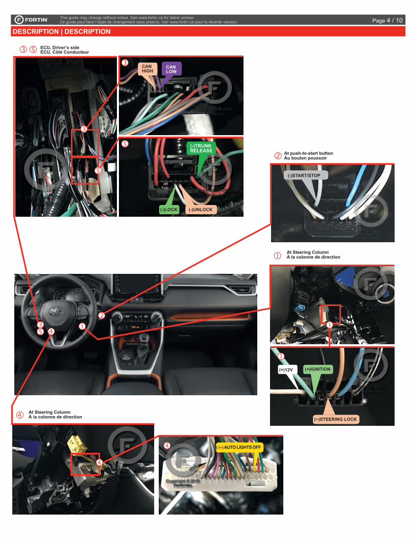
DESCRIPTION | DESCRIPTION
(+)12V (+)IGNITION
(~)STEERING LOCK
(-)UNLOCK(-)LOCK
At Steering Column À la colonne de direction
At Steering Column À la colonne de direction
At push-to-start button Àu bouton poussoir
ECU, Driver’s sideECU, Côté Conducteur
CAN HIGH
CAN LOW
(-)START/STOP
( ) AUTO LIGHTS OFF
(-)TRUNKRELEASE
Description | Description
Page 4 / 10

This guide may change without notice. See www.fortin.ca for latest version.Ce guide peut faire l’objet de changement sans préavis. Voir www.fortin.ca pour la récente version.
Yellow In A1Purple In A2
Purple/White In A3Green Out A4White Out A5
Orange In A6Orange/Black In A7
Dk.Blue In A8Red/Blue In A9
Lt.Blue/Black A10Black Out A11
Pink Out A12Yellow/Black In A13Brown/White Out A14
Pink/Black Out A15Purple/Yellow A16
Green/White A17Green/Red A18
White/Black A19Lt.Blue A20
C5 BrownC4 Gray/Black C3 GrayC2 Orange/BrownC1 Orange/Green
D6 White/RedD5 White/BlueD4 White/GreenD3 Yellow/RedD2 Yellow/BlueD1 Yellow/Green
A C
D
AUTOMATIC TRANSMISSION WIRING CONNECTION | SCHÉMA DE BRANCHEMENT TRANSMISSION AUTOMATIQUE
RAV
4
(-)START/STOP
A19
Ground
GROUNDMASSE
(-)STEERING LOCK
(-)AUTO LIGHTS OFF
(-)AUTO LIGHTS OFF
A10A20
(-)UNLOCK
(-)LOCK
7.5 A
mp
Fuse
Fus
ible
7.5 A
mp
B4 OR RS2A5 A1
(-)TRUNK RELEASE
(+)12V (+)IGNITION(-)START/STOP (-)UNLOCK
IDLE MODEMODE RALENTI
Back view 10-Pin Black Connector
Push-to-start button
Vue de dosConnecteur 10-Pins
Noir Bouton démarrage
1
(-)STEERING LOCK
GreyGris
TanBeige
WhiteBlanc
Lt.GreenVert Pâle
TanBeige
5
124567
D6
Front Black 30-pin Connector
ECU,Driver’s sideVue de dosConnecteur
Noir de 30 pinsECU, Côté conducteur
Back view 7-Pin
Black ConnectorSteering Lock
Connector Vue de dos
Connecteur Noir 7-Pins
Connecteur Steering Lock
20181615141211
4039383534333231
1098765432
3029282726252423
21
4241
1
22
13
3736
Back viewWhite 42-pin Connector
At Steering Column
Vue de dosConnecteur
Blancde 42 pins
À la colonnede direction
1
10
2345
678919
2021
17 16 1415 13 1218 11
27 25 24 23 2230 29 28 26
1
10
2
3456789
192021 17 16 1415
13 12
18
11
(-)LOCK
Lt. GreenVert Pâle
(~) CANLOW
(~) CANHIGH
C4C3
TanBeige
PurpleMauve
Front Black 21-pin Connector
ECU, Driver’s sideVue de dosConnecteurNoir de 21
pinsECU, Côté conducteur
10 9 8 7 6
4 3 2
3
D3(-)AUTO LIGHTS OFF
YellowJaune
1917
D1
CU
T
(-)TRUNKRELEASE
GreenVert
4
IDLE MODEMODE RALENTI
IDLE MODEMODE RALENTI
A2
A3
A4
A5
A6
A7
A8
A9
A10
A11A12A13
A14
A15
A16
A17
A18
A19
A20
C5C4
C3
C2C1
D6D5
D4D3D2D1
A1
D2
D4
C1C2
C5
A18
A17
A16
A15
A14
A12A11
A9
A7
A6
A4
B
RS1 Ground | Masse
Ground Masse
RS2 IN 12V Battery(+)
WITH | AVEC DATA-LINK:Direct connectionBranchement directe
RF-KIT REMOTESTARTER
KIT-RF DÉMARREURÀ DISTANCEWITH RF-KIT
AVEC KIT RF
OPTIONAL RF-KITKIT RF OPTIONNEL
B4B3B2B1
Cut | Coupez RedCut | Coupez Black
BlueWhite
WITHOUT RF-KITSANS KIT RF
B4 Red 12V Battery(+)B3 Black Ground | Masse
Ground Masse
(+) Ignition
CAN LOWCAN HIGH
(-) Unlock(-) Lock
(-) Lock/Unlock input external control | Contrôle du (-) verrouillage devérrouillage entrée externe
Start / Stop external controlContrôle de démarrage/arrêt externe
Start/Stop external
Hood pin
Hood pin only required on vehicles not equipped with a factory hood pin.Commutateur de capot requis seulement si le véhicule n'est pas équipé de cette composante.
SAFETY OVERRIDE SWITCHCOMMUTATEUR DE SÉCURITÉ
WIRE TO WIRE Connection Diagram | Diagramme de Branchements FIL À FIL
Page 5 / 10
This guide may change without notice. See www.fortin.ca for latest version.Ce guide peut faire l’objet de changement sans préavis. Voir www.fortin.ca pour la récente version.
Yellow In A1Purple In A2
Purple/White In A3Green Out A4White Out A5
Orange In A6Orange/Black In A7
Dk.Blue In A8Red/Blue In A9
Lt.Blue/Black A10Black Out A11
Pink Out A12Yellow/Black In A13Brown/White Out A14
Pink/Black Out A15Purple/Yellow A16
Green/White A17Green/Red A18
White/Black A19Lt.Blue A20
C5 BrownC4 Gray/Black C3 GrayC2 Orange/BrownC1 Orange/Green
D6 White/RedD5 White/BlueD4 White/GreenD3 Yellow/RedD2 Yellow/BlueD1 Yellow/Green
A C
D
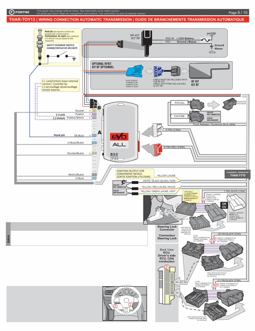
THAR-TOY13 | WIRING CONNECTION AUTOMATIC TRANSMISSION | GUIDE DE BRANCHEMENTS TRANSMISSION AUTOMATIQUE
A2
A3
A4
A5
A6
A7
A8
A9
A10
A11A12A13
A14
A15
A16
A17
A18
A19
A20
C5C4
C3
C2C1
D6D5
D4D3D2D1
A1
D2
D4
C1C2
C5
A18
A17
A16
A15
A14
A12A11
A9
A7
A6
A5
A4
RS1 Ground | MasseGround
Masse
RS2 IN 12V Battery(+)RF-KIT KIT RF
(-) Unlock(-) Lock
(-) Lock/Unlock input external control | Contrôle du (-) verrouillage devérrouillage entrée externe
SAFETY OVERRIDE SWITCHCOMMUTATEUR DE SÉCURITÉ
Hood pin
Hood pin only required on vehicles not equipped with a factory hood pin.Commutateur de capot requis seulement si le véhicule n'est pas équipé de cette composante.
RAV
4
2 1
2
ISOLATENOT CONNECTED---------------------ISOLERNON BRANCHÉ
ISOLATENOT CONNECTED---------------------ISOLERNON BRANCHÉ
5 PIN CONN.
B
OPTIONAL RFKITKIT RF OPTIONNEL
RF KITKIT RF
CABLE MUST BE INCLUDED WITH THE RF KIT. CÂBLE DOIT ÊTRE INCLUS AVEC LE KIT RF.
BLUE FEMALE CONNNECTOR CONNECTEUR FEMELLE BLEU
(+)12V
6 PIN RED CONN.
EVO-ALL
EVO-ONE
Trunk Release | Ouverture de la valise
IGNITION OUTPUT FOR CONVENIENT DEVICE. SORTIE IGNITION UTILITAIRE.
ENGINE
START
STOP
YELLOW/RED | JAUNE/ROUGE
YELLOW/GREEN | JAUNE/VERT 7 PIN WHITE CONN.
T-HARNESS - HARNAIS EN T
THAR-TY70
WHITE/BLACK | BLANC/NOIR
YELLOW | JAUNE
1
Steering Lock Connector
Connecteur Steering Lock
T-HARNESS - HARNAIS EN T
THAR-TY70
30 PIN BLACK CONN.
2 B
21 PIN BLACK CONN.
2 A
Back View ECU,
Driver’s sideECU, Côté
conducteur
OROU
7 PINS MALE T-HARNESS BLACK OR WHITE PLUGCONNECTEUR MÂLE NOIR OU BLANC DU T-HARNAIS
FEMALE T-HARNESS BLACK PLUGCONNECTEUR FEMELLE NOIR DU T-HARNAIS
FEMALE T-HARNESS WHITE PLUGCONNECTEUR FEMELLE BLANC DU T-HARNAIS
MALE VEHICLE BLACK PLUG
CONNECTEUR NOIR MÂLE DU
VÉHICULE
FEMALE T-HARNESS PLUGCONNECTEUR FEMELLEDU T-HARNAIS
FEMALE T-HARNESS PLUGCONNECTEUR FEMELLEDU T-HARNAIS
30 PINMALE T-HARNESS PLUGCONNECTEUR MÂLEDU T-HARNAIS
21 PINMALE T-HARNESS PLUGCONNECTEUR MÂLEDU T-HARNAIS
MALE VEHICLE BLACK PLUGCONNECTEUR MÂLE NOIRDU VÉHICULE
MALE VEHICLE BLACK PLUGCONNECTEUR NOIR MÂLE
DU VÉHICULE
THAR-TOY13 - THarness Diagram | Diagramme harnais en T
Page 6 / 10
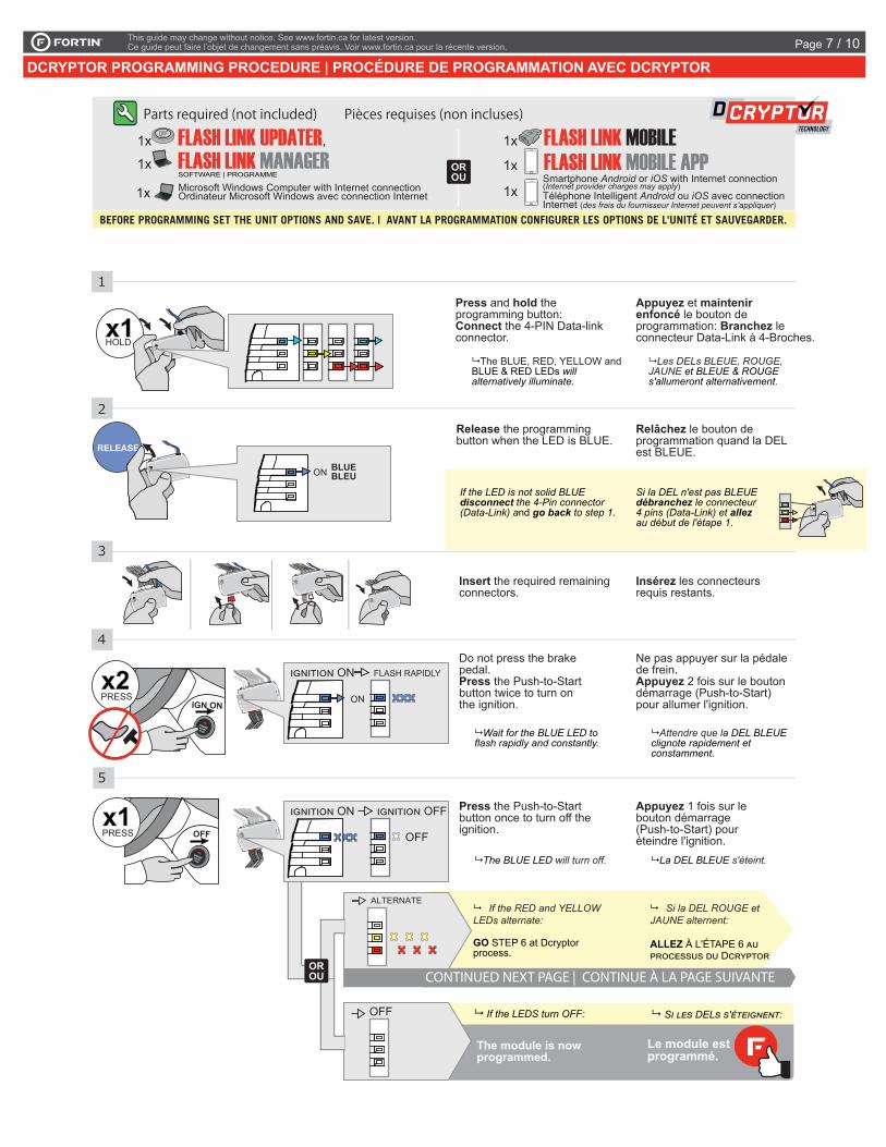
Insert the required remaining connectors.
Insérez les connecteurs requis restants.
Release the programming button when the LED is BLUE.
Relâchez le bouton de programmation quand la DEL est BLEUE.
2
3
1
5
4
The BLUE, RED, YELLOW and BLUE & RED LEDs will alternatively illuminate.
Les DELs BLEUE, ROUGE, JAUNE et BLEUE & ROUGE s'allumeront alternativement.
The module is now programmed.
Le module est programmé.
CONTINUED NEXT PAGE | CONTINUE À LA PAGE SUIVANTE
If the LEDS turn OFF:
If the RED and YELLOW LEDs alternate:
GO STEP 6 at Dcryptor process.
Si la DEL ROUGE et JAUNE alternent:
ALLEZ À L'ÉTAPE 6 AU PROCESSUS DU DCRYPTOR
ALTERNATE
OROU
OFF SI LES DELS S'ÉTEIGNENT:
RELEASE
If the LED is not solid BLUE disconnect the 4-Pin connector (Data-Link) and go back to step 1.
ON BLUE BLEU
Si la DEL n'est pas BLEUE débranchez le connecteur 4 pins (Data-Link) et allez au début de l'étape 1.
FLASH RAPIDLY
ON
IGNITION ON
IGNITION ON IGNITION OFF
OFF
Press and hold the programming button:Connect the 4-PIN Data-link connector.
Appuyez et maintenir enfoncé le bouton de programmation: Branchez le connecteur Data-Link à 4-Broches.x1
HOLD
IGN ON
x2PRESS
OFFx1PRESS
Press the Push-to-Start button once to turn off the ignition.
Appuyez 1 fois sur le bouton démarrage (Push-to-Start) pour éteindre l'ignition.
The BLUE LED will turn off. La DEL BLEUE s'éteint.
Do not press the brake pedal.Press the Push-to-Start button twice to turn on the ignition.
Ne pas appuyer sur la pédale de frein.Appuyez 2 fois sur le bouton démarrage (Push-to-Start) pour allumer l'ignition.
Wait for the BLUE LED to flash rapidly and constantly.
Attendre que la DEL BLEUE clignote rapidement et constamment.
This guide may change without notice. See www.fortin.ca for latest version.Ce guide peut faire l’objet de changement sans préavis. Voir www.fortin.ca pour la récente version.
DCRYPTOR PROGRAMMING PROCEDURE | PROCÉDURE DE PROGRAMMATION AVEC DCRYPTOR
Parts required (not included) Pièces requises (non incluses)
1x FLASH LINK UPDATER,
1x FLASH LINK MANAGER
1x FLASH LINK MOBILE1x FLASH LINK MOBILE APP
SOFTWARE | PROGRAMME Smartphone Android or iOS with Internet connection (Internet provider charges may apply)Téléphone Intelligent Android ou iOS avec connection Internet (des frais du fournisseur Internet peuvent s’appliquer)
OROU
Microsoft Windows Computer with Internet connectionOrdinateur Microsoft Windows avec connection Internet1x 1x
BEFORE PROGRAMMING SET THE UNIT OPTIONS AND SAVE. | AVANT LA PROGRAMMATION CONFIGURER LES OPTIONS DE L'UNITÉ ET SAUVEGARDER.
Key Bypass Programming Procedure | Procédure de Programmation Contournement de Clé
Page 7 / 10

EVO-ALL
Disconnect all the connectors and after the Data-Link (4-pins) connector.
Débranchez tous les connecteurs et ensuite le connecteur Data-Link (4-pins).
6
REMOTE STARTER / ALARM VERIFICATION PROCEDURE | PROCÉDURE DE VÉRIFICATION DU DÉMARREUR À DISTANCE / ALARMETest the remote starter. Remote start the vehicle.Testez le démarreur à distance. Démarrez le véhicule à distance.
The module is now programmed.Le module est programmé.
*Pièces requises (non incluses)
Use the tool: FLASH LINK UPDATER or FLASH LINK MOBILEto visit the DCryptor menu.
Utilisez l'outil: FLASH LINK UPDATER ou FLASH LINK MOBILEpour visiter le menu DCryptor.
*Parts required (not included)
FLASH LINK UPDATER*
FLASH LINK MOBILE*
FLASH LINK MANAGER*SOFTWARE | PROGRAMME
Microsoft Windows Computer with Internet connection*
Ordinateur Microsoft Windows avec connection Internet*
VEHICLE'S OBDII CONNECTOR
CONNECTEUR OBDII DU VÉHICULE
OROU
Smartphone* (Internet provider chargesmay apply)Téléphone Intelligent* (des frais du fournisseurInternet peuvent s’appliquer)
AFTER DCRYPTOR PROGRAMMING COMPLETEDGo back to the vehicle and reconnect the 4-Pin (Data-Link) connector and after, all the remaining connector.
APRÈS LA PROCÉDURE DE PROGRAMMATION DCRYPTOR COMPLETÉE : retournez au véhicule etrebranchez le connecteur 4-pins (Data-Link) et après, tous les connecteurs du EVO-ALL.
EVO-ALL
7
8
This guide may change without notice. See www.fortin.ca for latest version.Ce guide peut faire l’objet de changement sans préavis. Voir www.fortin.ca pour la récente version.
KEY BYPASS PROGRAMMING PROCEDURE 2/2 | PROCÉDURE DE PROGRAMMATION CONTOURNEMENT DE CLÉ 2/2Page 8 / 10

Remote start
the vehicle.
Démarrez à distance.
Enter the vehicle
with the Smart-Key.
Entrez dans le véhicule avec la clé intelligente
(Smart-Key) sur vous.
Press the Push-to-Start button to start the vehicle.
Appuyez sur le bouton
démarrage pour
démarrer le véhicule.
The vehicle can now be
put in to gear and driven.
Vous êtes maintenant
prêt à embrayer et prendre la
route.
IGN ON
All doors must
be closed.
Toutes les portes doivent
être fermées.
Press the brake
pedal.
Appuyez sur la
pédale de frein.
The module will shut down the
vehicle as soon as the drivers
door is opened.Lors de
l'ouverture de la porte conducteur
le véhicule s'éteindra par
sécurité.
OFF
Unlock the doors with either: • The OEM remote • The remote-starter remote• Or the proximity remote
Déverrouillez les portes avec soit: • la télécommande d'origine• la télécomande du démarreur à distance• ou la télécommande de proximté.
START UNLOCK
This guide may change without notice. See www.fortin.ca for latest version.Ce guide peut faire l’objet de changement sans préavis. Voir www.fortin.ca pour la récente version.
REMOTE STARTER FUNCTIONALITY | FONCTIONNALITÉS DU DÉMARREUR À DISTANCE
Remote starter functionality | Fonctionalité du démarreur à distance
Page 9 / 10
ALL
Service No : 000 102 04 2536
Date: xx-xx
INTERFACE MODULE
Made in CanadaPATENTS PENDING US: 2007-228827-A1
www.fortinbypass.com
HARDWARE VERSION FIRMWARE VERSION
Module label | Étiquette sur le module
Notice: Updated Firmware and Installation GuidesUpdated fi rmware and installation guides are posted on our web site on a regular basis. We recommend that you update this module to the latest fi rmware and download the latest installation guide(s) prior to the installation of this product.
Notice: Mise à jour microprogramme et Guides d’installationsDes mises à jour du Firmware (microprogramme) et des guides d’installation sont mis en ligne régulièrement. Vérifi ez que vous avez bien la dernière version logiciel et le dernier guide d’installation avant l’installation de ce produit.
WARNINGThe information on this sheet is provided on an (as is) basis with no representation or warranty of accuracy whatsoever. It is the sole responsibility of the installer to check and verify any circuit before connecting to it. Only a computer safe logic probe or digital multimeter should be used. FORTIN ELECTRONIC SYSTEMS assumes absolutely no liability or responsibility whatsoever pertaining to the accuracy or currency of the information supplied. The installation in every case is the sole responsibility of the installer performing the work and FORTIN ELECTRONIC SYSTEMS assumes no liability or responsibility whatsoever resulting from any type of installation, whether performed properly, improperly or any other way. Neither the manufacturer or distributor of this module is responsible of damages of any kind indirectly or directly caused by this module, except for the replacement of this module in case of manufacturing defects. This module must be installed by qualifi ed technician. The information supplied is a guide only. This instruction guide may change without notice. Visit www.fortinbypass.com to get the latest version.
MISE EN GARDE L’information de ce guide est fournie sur la base de représentation (telle quelle) sans aucune garantie de précision et d’exactitude. Il est de la seule responsabilité de l’installateur de vérifi er tous les fi ls et circuits avant d’effectuer les connexions. Seuls une sonde logique ou un multimètre digital doivent être utilisés. FORTIN SYSTÈMES ÉLECTRONIQUES n’assume aucune responsabilité de l’exactitude de l’information fournie. L’installation (dans chaque cas) est la responsabilité de l’installateur effectuant le travail. FORTIN SYSTÈMES ÉLECTRONIQUES n’assume aucune responsabilité suite à l’installation, que celle-ci soit bonne, mauvaise ou de n’importe autre type. Ni le manufacturier, ni le distributeur ne se considèrent responsables des dommages causés ou ayant pu être causés, indirectement ou directement, par ce module, excepté le remplacement de ce module en cas de défectuosité de fabrication. Ce module doit être installé par un technicien qualifi é. L’information fournie dans ce guide est une suggestion. Ce guide d’instruction peut faire l’objet de changement sans préavis. Consultez le www.fortinbypass.com pour voir la plus récente version.
Copyright © 2006-2018, FORTIN AUTO RADIO INC ALL RIGHTS RESERVED PATENT PENDING
TECH SUPPORTTél: 514-255-HELP (4357) 1-877-336-7797
ADDENDUM GUIDEWEB UPDATE | MISE À JOUR INTERNET
www.fortinbypass.com
EVO-ALL
Disclaimer | Avertissement
Page 10 / 10


![3 1. [20 ]74. 29 - fortin.ca](https://img.dokumen.tips/doc/110x75/62e027d133684e21667927c1/3-1-20-74-29-.jpg)