Embed Size (px)
Citation preview

PURSUING TESLA’S VISION
Gary Peterson

PURSUING TESLA’S VISION Creation of a Tesla Curriculum
Gary Peterson Tesla Memorial Society
January 11, 2014

ii
© 2014, Gary Peterson, All Rights Reserved. Published Under the GNU Free Documentation License.
Gary Peterson P.O. Box 2001
Breckenridge, CO 80424 United States of America
(970) 453‐9293 www.teslaradio.com

iii
Contents
Preface v Introduction vii Part I – An Engineering Legacy
AC Motors and Generators ............................................................................ 1
The Superconducting Electrical Transmission Line ........................................ 8
X‐Ray Diagnostics ........................................................................................... 11
The High Tension Induction Coil Transformer ................................................ 17
High Voltage Capacitors ................................................................................. 21
High Speed Switches ...................................................................................... 25
The Radio‐frequency Electrical Power Supply ............................................... 29
High Frequency Fluorescent Lighting ............................................................. 33
High Frequency Incandescent Lighting .......................................................... 36
Radio and TV Broadcasting, and Wireless Telecommunications ................... 39
Radio‐frequency Detectors ............................................................................ 43
The Crystal‐controlled Electrical Oscillator .................................................... 47
The Heterodyne Radio Receiver ..................................................................... 51
Stroboscopy ................................................................................................... 55
Radio Control and Robotics ............................................................................ 61
Spread Spectrum Signal Processing ............................................................... 66
The Electronic Logic Gate ............................................................................... 68
Pumps and Turbines ....................................................................................... 71
Part II – Free Energy
From Crooks’ Radiometer to Hot Dry Rock Geothermal ............................... 78
Self‐Acting Machines ...................................................................................... 81
The Liberation of Atomic Energy .................................................................... 82
Part III – Tesla Coils and World Wireless
Tesla’s Oscillator ............................................................................................. 87
The World Wireless System ........................................................................... 111
Part IV – A Theoretical Foundation ........................................................................... 119

v
Preface
In the children’s game ‘Pass it Along,’ a group of kids line up and the first one whispers a
message to the next and so on down the line until the last player announces the received
message to the entire group. “Errors typically accumulate in the retellings, so the statement
announced by the last player differs significantly, and often amusingly, from the one uttered by
the first. Reasons for changes include anxiousness or impatience, erroneous corrections, and
that some players may deliberately alter what is being said to guarantee a changed message by
the end of the line.” [Wikipedia]
Over the last one‐hundred or so years, the largely word‐of‐mouth recounting of Tesla’s
engineering legacy has, in certain aspects, resembled this game. Some facts have been
obscured and errors have entered into picture that is being drawn of this pioneering inventor’s
work. Faced with the large volume of material now available, particularly on the Internet, it‘s
becoming more and more difficult to distinguish between truth and that which is only hearsay,
having no scientific basis in fact.
Teachers must have adequate tools at their disposal to counteract this phenomenon. This is the
primary goal of the proposed Tesla Curriculum; to harness the student’s eagerness, to foster
deliberation and critical thinking, to encourage rigor and attention to detail, and goodness and
honesty in all that they seek to do throughout their adult lives.
The following presentation is intended specifically for educators who wish to use the example
of Nikola Tesla in guiding their students who are thinking about a career in the physical
sciences, and the fields of mechanical and electrical engineering.

vii
Introduction
Tesla's fundamental design for an AC power system evolved over the years. Having stood the
test of time, the result has been an improvement of the human condition. The same holds true
for his four‐tuned‐circuit wireless transmission‐reception system, and other innovations that
are described in Part 1 of this presentation. This being said, it's also worthwhile to pay some
attention to those discoveries that have received only limited consideration as to their
practicality and or usefulness.
What can be done to expedite a Tesla‐technology based industrial renaissance?
Tesla is known to have said,
If you are desirous of hastening the accomplishment of still greater and further‐reaching
wonders you can do no better than by emphatically opposing any measure tending to
interfere with the free commercial exploitation of water power and the wireless art. [1]
What are the political hurdles associated with pursuit of the yet‐to‐be‐adopted portions of
Tesla's engineering legacy?
So absolutely does human progress depend on the development of [water power and
the wireless art] that the smallest impediment, particularly through the legislative
bodies of this country, may set back civilization and the cause of peace for centuries. [1]
What does the future hold for wireless telecommunications?
The following words were written about the World Wireless system in 1905.
It is not a dream, it is a simple feat of scientific electrical engineering, only expensive—
blind, faint‐hearted, doubting world! [2]
And, this was written in 1908.
Nothing could be further from my thought than to call wireless telephony around the
world “the greatest achievement of humanity” as reported. This is a feat which,
however stupifying, can be readily performed by any expert. I have myself constructed
a plant for this very purpose. The wireless wonders are only seeming, not results of
exceptional skill, as popularly believed. The truth is the electrician has been put in
possession of a veritable lamp of Aladdin. All he has to do is to rub it. Now, to rub the
lamp of Aladdin is no achievement. [1]

viii
What are the risks associated with Tesla technology?
As with the harnessing of nuclear reactions for the generation of electrical energy and for other
useful purposes, the development of World Wireless carries with it certain hazards to life and
human welfare. Perhaps the greatest of these is the potential for weaponization,
Even now wireless power plants could be constructed by which any region of the globe
might be rendered uninhabitable without subjecting the population of other parts to
serious danger or inconvenience. [1]
There are also legitimate concerns that implementation of World Wireless system technology
at a significant power level might have adverse environmental impacts.
The same as with any other enterprise that deals with high energy levels, there are other
potential dangers. The possibility of an industrial accident is ever‐present, so the apparatus
must be designed and operated with safety in mind.
Is the Tesla wireless system an invention whose time has come?
While there might be some local and regional advantages associated with its implementation,
assuming the basic principles can be rigorously validated, the greatest benefit will accrue if the
system is adopted globally. In any case, problems such as fresh water resource management,
food and energy production, climate change and managing the risks associated with unforeseen
natural disasters must eventually be addressed with resolute action on a global scale.
Tesla dedicated his entire adult life to the design and improvement of instruments for "the
service of mankind,“ forming in his mind an image of a world in which all work is performed in
an efficient and harmonious manner. AC power, broadcasting, wireless telecommunications,
personal computing, high‐efficiency fluorescent lighting, X‐ray diagnostics and, more recently,
WiTricity charging stations are now components of life on Earth that serve to fulfill this vision.
While these innovations have changed our world for the better, there are unused Tesla
inventions still waiting in the wings that may have the capacity to be of an equivalent and
possibly greater value to society. To paraphrase Marshall McLuhan, 'Firstly, we must learn and
then we must teach these things in all their subtle details and abundances.'
References
1. Tesla, Nikola, "Mr. Tesla's Vision," Letter to the Editor, New York Times, April 21, 1908, p. 5, col. 6.
2. Tesla, Nikola, "The Transmission of Electrical Energy without Wires as a Means for Furthering Peace," Electrical World and Engineer, January 7, 1905.

Let’s begin by taking a look at those engineering marvels of years gone by as they presentlyexist in the Modern Era.
1

We’ll start with low‐frequency, heavy current electric power generation, transmission andutilization.
2

This is the control room of the Watts Bar nuclear power plant near Spring City, Tennessee.This station alone produces 1,200 megawatts of electricity—enough to power 250,000homes.
3

Here is an interior shot of the Edward Dean Adams Power Station at Niagara Falls during itsconstruction in 1896. We see the armature of a 5000 H.P. Westinghouse Generator in theprocess of being assembled. Notice the two generators already spinning in thebackground.
4

This shows a 40 H.P. 2‐phase induction motor ready to drive some factory machinery.
5

Here is Tesla with an array of poly‐phase AC induction motors that embody his rotating magnetic field concept.
[Nikola Tesla Photograph Archive.]
6

This is a drawing from one of Tesla’s original patents related to the poly‐phase AC powersystem.
A motor is employed in which there are two or more independent circuits throughwhich alternate currents are passed at proper intervals, in the manner hereinafterdescribed, for the purpose of effecting a progressive shifting of the magnetism or ofthe “lines of force” in accordance with the well‐known theory, and a consequentaction of the motor It is obvious that a proper progressive shifting of the lines ofaction of the motor. It is obvious that a proper progressive shifting of the lines offorce may be utilized to set up a movement or rotation of either element of themotor, the armature, or the field‐magnet, and that if the currents directed throughthe several circuits of the motor are in the proper direction no commutator for themotor will be required; but to avoid all the usual commutating appliances in thesystem I prefer to connect the motor‐circuits directly with those of a suitablealternate‐current generator. The practical results of such a system, its economicaladvantages, and the mode of its construction and operation will be described morein detail by reference to the accompanying diagrams and drawings. – U.S. PatentNo. 381,968, ELECTRO‐MAGNETIC MOTOR, May 1, 1888. Application filed October12, 1887.
7

Tesla patented a means for reducing the resistance of electrical conductors by coolingconventional wires with liquid air.
8

Electric utility companies are presently researching electrical transmission lines constructedof sophisticated high‐temperature superconducting cable that delivers more power withgreater voltage control and current density. By “high temperature” we meansuperconductivity at the temperature of liquid nitrogen. Under normal atmosphericpressure the boiling point of liquid air is approximately 78 K (‐319°F) and that of liquidnitrogen approximately 77.2 K (‐320.44°F).
The use of superconducting cable will help utilities meet increasing demands withoutThe use of superconducting cable will help utilities meet increasing demands withoutbuilding additional transmission towers or installing new underground rights‐of‐way undercrowded city streets.
9

The related Tesla patent is associated with his work in the area of radio‐frequency (RF)power processing.
High‐temperature superconductor technology can be applied by researchers who arereproducing Tesla’s original wireless work.
10

Tesla’s researches in the area of RF power processing went hand‐in‐hand with experimentsin which high voltage vacuum discharge tubes were used for the production of X rays.
11

This is a modern radiology suite in which X‐ray imaging is used to both diagnose and assistin the treatment of diseases and injuries visualized within the human body. The X rayspenetrate the portion of the body to be examined and by controlling the energy and thelength of exposure, a high contrast image is formed on silver‐impregnated film or a plate ofsensors that converts the signals generated into digital information, which is transmittedand converted into an image displayed on a computer screen.– http://en.wikipedia.org/wiki/Radiology
12

Wilhelm Conrad Röntgen discovered the X ray in 1895 and received the first Nobel Prize inPhysics for their discovery in 1901. In 1895 Tesla was also observing X‐ray related effects inthat exposed photographic plates documenting his work were being inexplicably spoiled.His follow‐up investigations in this area were significantly delayed when the South 5th
Avenue laboratory was destroyed by fire.
This is an example of an X‐ray image or “radiograph” created by Tesla.
13

This is an illustration of a tube used in investigations performed to determine the X ray’sexact point of origin, the conditions necessary for it’s production, and matters associatedwith secondary emission.
The diagram shows a Lenard tube of improved design, consisting of a tube T of thickglass tapering towards the open end, or neck n, into which is fitted an aluminumcap A, and a spherical cathode e, supported on a glass stem s, and platinum wire wsealed in the opposite end of the tube as usual The aluminum cap A as will besealed in the opposite end of the tube as usual. The aluminum cap A, as will beobserved, is not in actual contact with the ground glass wall, being held at a smalldistance from the latter by a narrow and continuous ring of tinfoil r. The outer spacebetween the glass and the cap A is filled with cement c, in a manner which I shalllater describe. F is a Roentgen screen such as is ordinarily used in making theobservations. – Nikola Tesla: Lecture Before the New York Academy of Sciences –April 6, 1897, pp. 96‐99.
14

Tesla's independent discovery of X‐Rays, unlike Roentgen's, was primarily based onsources which produced X‐Rays by vacuum high field emission and the process nowknown as bremsstrahlung. While Roentgen employed a gaseous discharge tubeutilizing electron avalanche, Tesla's cold cathode tubes worked best with highvacuum. Tesla's distinctive approach presaged the way for high energy particleaccelerators, permitting the utilization of megavolt potentials, single electrodetubes, atmospheric bremsstrahlung, and a variety of intense beam techniques. Asusual he was years ahead with his inventions: Fowler and Nordheim's quantumusual, he was years ahead with his inventions: Fowler and Nordheim s quantummechanical considerations, necessary to understand Tesla's sources, were notavailable for another 32 years! By then Tesla was developing a macroscopic chargedparticle beam. – Kenneth and James Corum, 1994
15

17

“Inductorium” is an archaic term for the commercial iron‐core induction coil transformer,common during Tesla’s time. The induction coil transformer was used up to and throughthe 1890s for high‐voltage research. Tesla improved upon the “commercial coil” creatingwhat is known as the “high tension induction coil.” A present‐day form of induction coil isfound in the automobile ignition system.
18

Here is a patent drawing of Tesla’s high‐tension induction coil, also known as the “Teslacoil.”
19

21

This is a present‐day high voltage capacitor.
22

Here are two of Tesla’s capacitor designs, used as a component of his high power wirelesstransmitter.
(A word on nomenclature. What Tesla referred to as a “condenser” is, in modern terms, a“capacitor.”)
23

Tesla devoted considerable time and effort to the design and construction of high speedcircuit controllers.
25

The insulated‐gate bipolar transistor (IGBT) is a three‐terminal power semiconductor deviceprimarily used as an electronic switch and in newer devices is noted for combining highefficiency and fast switching. It switches electric power in many modern appliances:Variable‐Frequency Drives (VFDs), electric cars, trains, variable speed refrigerators, air‐conditioners and even stereo systems with switching amplifiers. Since it is designed to turnon and off rapidly, amplifiers that use it often synthesize complex waveforms with pulsewidth modulation and low‐pass filters. In switching applications modern devices boastpulse repetition rates well into the ultrasonic range—frequencies which are at least tenpulse repetition rates well into the ultrasonic range frequencies which are at least tentimes the highest audio frequency handled by the device when used as an analog audioamplifier. – http://en.wikipedia.org/wiki/Insulated‐gate_bipolar_transistor
The metal‐oxide‐semiconductor field‐effect transistor (MOSFET, MOS‐FET, or MOS FET) is atransistor used for amplifying or switching electronic signals. Although the MOSFET is afour‐terminal device with source (S), gate (G), drain (D), and body (B) terminals,[1] the body(or substrate) of the MOSFET often is connected to the source terminal, making it a three‐terminal device like other field‐effect transistors. Because these two terminals arenormally connected to each other (short‐circuited) internally, only three terminals appearin electrical diagrams. The MOSFET is by far the most common transistor in both digitaland analog circuits, though the bipolar junction transistor was at one time much morecommon. – http://en.wikipedia.org/wiki/MOSFET
26

In 1922, the Institute of Radio Engineers (IRE) selected Lee de Forest as the fifth recipientof its Medal of Honor. He was cited for "his major contributions to the communicationsarts and sciences, as particularly exemplified by his invention of that outstandinglysignificant device: the three‐electrode vacuum tube, and his work in the fields of radiotelephonic transmission and reception.” He served a term as president of the IRE in 1930.He also received the Edison Medal of the American Institute of Electrical Engineers (AIEE) in1946, becoming one of only seven to receive both the Medal of Honor and the EdisonMedal prior to 1962 He became known for having a rather flamboyant personality andMedal prior to 1962. He became known for having a rather flamboyant personality andwas a very prolific inventor, receiving more than 300 patents during his career.– http://ieeexplore.ieee.org/xpl/articleDetails.jsp?arnumber=1369709
27

Here is one of Tesla’s high speed switches, also known as a “circuit controller” or “break.”His pioneering advances in the area of radio‐frequency power processing would have beenimpossible without these sophisticated devices.
In some of the forms of apparatus which I have heretofore devised for carrying outthis invention I have employed a mechanism for making and breaking an electriccircuit or branch thereof for the purpose of charging and discharging the condenser,and my present application is based upon a novel and improved form of device forand my present application is based upon a novel and improved form of device forthis purpose, which may be generally styled a “circuit‐controller.”– U.S. Patent No. 609,251, ELECTRIC‐CIRCUIT CONTROLLER, August 16, 1898.Application filed June 8, 1897. Renewed June 15, 1898.
28

29

Present‐day high efficiency fluorescent lighting systems depend upon a transistorizedradio‐frequency power supply to energize the lamp. A common example of such a systemis the Compact Fluorescent Lamp (CFL).
The CFL’s internal circuit board carries all of the components present in Tesla’s original highvoltage RF power supply, in miniaturized form.
30

While initially designed for high frequency lighting, Tesla also used his high voltageresonance transformer—the Tesla coil—for wireless propagation experiments.
31

This circuit controller patent drawing also shows the layout of the primary capacitor and RFtransformer along with a circuit diagram, including an external electrode fluorescent lamp.
32

Tesla experimented with what he called "phosphorescent" lamps, but it was Frenchphysicist Alexandre‐Edmond Becquerel (1820‐1891) who first conceived the idea of placinga fluorescent coating on the inner surface of a high voltage gas discharge tube.
Tesla’s investigations in the area of high‐voltage RF power processing did result in the veryfirst high efficiency, high frequency lighting ballasts. His seminal lectures on the topic ofhigh frequency lighting are, Experiments With Alternate Currents of Very High Frequencyand Their Application to Methods of Artificial Illumination Experiments with Alternatingand Their Application to Methods of Artificial Illumination, Experiments with AlternatingCurrents of High Potential and High Frequency and On Light and Other High FrequencyPhenomena. The world's first commercial fluorescent lamps, introduced by theWestinghouse Electric Company at the 1939 New York World's Fair, were of the low‐voltage50‐60 Hz hot cathode type still in common use today. Only since the late 1980s haveefficient high frequency lighting systems gained wider acceptance.
33

While Tesla did not invent the fluorescent lamp, it seems he was the first person toconceive of the idea of bending the tube back upon itself in order to make the lamp morecompact.
34

In Fig. 32 a wide tube T was sealed to a smaller W‐shaped tube U, ofphosphorescent glass. In the tube T was placed a coil C of aluminium wire, theends of which were provided with small spheres t and t1 of aluminium, andreached into the U tube. The tube T was slipped into a socket containing a primarycoil through which usually the discharges of Leyden jars were directed, and therarefied gas in the small U tube was excited to strong luminosity by the high‐tension currents induced in the coil C. – Experiments with Alternate Currents ofHigh Potential and High Frequency IEE Address London February 1892High Potential and High Frequency, IEE Address, London, February 1892.
In previous patents granted to me I have shown and described methods andapparatus for the conversion and utilization of electrical current of very highfrequency based upon the principle of charging a condenser or a circuit possessingcapacity and discharging the same generally through the primary of a transformer,the secondary of which constituted the source of working current and under suchconditions as to yield a vibrating or rapidly‐intermittent current. – U.S. Patent No.609,251, ELECTRIC‐CIRCUIT CONTROLLER, August 16, 1898. Application filed June8, 1897. Renewed June 15, 1898.
35

The possibilities of high frequency incandescent lighting are yet to be developed. It seemselectrical engineers have not even scratched the surface of this technology.
36

Single and dual electrode incandescent lamps require a more energetic RF power supplythan the fluorescent lamp. This may start to explain the lack of attention these high‐efficiency lamp designs have received.
37

The fields of wireless telecommunications and broadcasting owe their existence to Tesla’snumerous pioneering inventions in the area of radio‐frequency power processing.
39

Tesla is known for having developed the world’s first practical radio transmitter. His high‐power transmitter was based upon his high power, high voltage, high frequency powersupply, originally intended for lighting purposes.
This is the Armstrong Tower, also known as Alpine Tower, a 129.5‐meter lattice structurebuilt by Edwin Armstrong in 1938 at Alpine, New Jersey and used for his transmissionexperiments that led to modern FM radio. – http://en.wikipedia.org/wiki/Armstrong_Tower
40

Tesla pioneered practical wireless transmission by means of electromagnetic radiation. Heis credited with the radio telecommunications transmission‐reception system consisting offour tuned circuits, two at the transmitter and two at the receiver. Other early participantsin the field of wireless telecommunications and broadcasting include Oliver Lodge,Guglielmo Marconi, Ferdinand Braun, Alexander Popov, Adolf Slaby, Georg von Arco,Reginald Fessenden, Jostein Pedersen, Julio Cervera Baviera, Charles “Doc” Herrold,Valdemar Poulsen, Mihajlo Pupin, Fritz Lowenstein, Edwin H. Armstrong, and David Sarnoff.
41

Speaking about his wireless system Tesla said,
If you take this fourth circuit entirely away, and leave only that circuit here, theantenna and the ground connection, then that is the ideal condition for the flow ofthe current in this receiving circuit. Any other circuit you bring near to that excitedcircuit with the antenna will draw energy from it and tend to pull down theoscillation in the latter circuit and diminish the resonant rise. No matter what youlink to the antenna circuit and how you link it the energy you take away from thatlink to the antenna circuit, and how you link it, the energy you take away from thatcircuit will always tend, being frictional, to diminish the resonant rise.
Now the art consists in reducing as much as possible the energy necessary for thesignal, and in that regard the evolution of detectors as the audion of Dr. De Forest,and of other such devices, is in the proper direction, rational, and good. But theideal condition requires that you should have here a device which only requirespressure and no current; and once you have a device which does not need anycurrent but merely acts by pressure and has no internal capacity, so that there willbe no capacity current in the circuit, then that is the ideal receiver. – Nikola Tesla OnHis Work With Alternating Currents and Their Application to Wireless Telegraphy,Telephony, and Transmission of Power, Tesla Presents Series Part 1, Nikola Tesla;Leland I. Anderson, Editor, pp. 99‐100.
43

The field‐effect transistor (FET) is a transistor that uses an electric field to control the shapeand hence the conductivity of a channel of one type of charge carrier in a semiconductormaterial. FETs are unipolar transistors as they involve single‐carrier‐type operation. Theconcept of the FET predates the bipolar junction transistor (BJT), though it was notphysically implemented until after BJTs due to the limitations of semiconductor materialsand the relative ease of manufacturing BJTs compared to FETs at the time.– http://en.wikipedia.org/wiki/Field‐effect_transistor
44

The Audion was an electronic amplifying vacuum tube invented by American electricalengineer Lee De Forest in 1906. It was the first triode, consisting of a partially evacuatedglass tube containing three electrodes; a heated filament, a grid, and a plate. It isimportant in the history of technology because it was the first widely used tube whichcould amplify; a small electrical signal applied to the grid could control a larger currentflowing from the filament to plate.
Unlike later vacuum tubes the primitive Audion had a small amount of gas in the tubeUnlike later vacuum tubes, the primitive Audion had a small amount of gas in the tube,thought to be necessary by De Forest, which limited the dynamic range and gave itnonlinear characteristics and erratic performance. Originally invented as a radio receiverdetector by adding a grid electrode to the Fleming valve, it found little use until itsamplifying ability was recognized around 1912 by several researchers, who used it to buildthe first amplifying radio receivers and electronic oscillators. The many practicalapplications for amplification motivated its rapid development, and the original Audion wassuperseded within a few years by improved versions with higher vacuum, developed byIrving Langmuir at GE and others. These were the first modern "hard vacuum" triodes.– http://en.wikipedia.org/wiki/Audion
45

Figure 9 of The True Wireless is captioned, “The Forerunner of the Audion‐the MostSensitive Wireless Detector Known, as Described by Tesla In His Lecture Before theInstitution of Electrical Engineers, London, February, 1892.”
My confidence that a signal could be easily flashed around the globe wasstrengthened thru the discovery of the "rotating brush," a wonderful phenomenonwhich I have fully described in my address before the Institution of ElectricalEngineers London in 1892 [Experiments with Alternate Currents of High PotentialEngineers, London, in 1892 [Experiments with Alternate Currents of High Potentialand High Frequency], and which is illustrated in Fig. 9. This is undoubtedly the mostdelicate wireless detector known, but for a long time it was hard to produce and tomaintain in the sensitive state. These difficulties do not exist now and I am lookingto valuable applications of this device, particularly in connection with the high‐speed photographic method, which I suggested, in wireless, as well as in wire,transmission. – The True Wireless, Electrical Experimenter, May 1919.
46

A little‐known Tesla contribution to the field of wireless telecommunications and radio‐frequency power processing is the isochronous electro‐mechanical oscillator.
47

The crystal‐controlled electrical oscillator is used in wireless transmitters and receivers,along with numerous electronics devices such as personal computers, digital clocks andvarious scientific instruments.
48
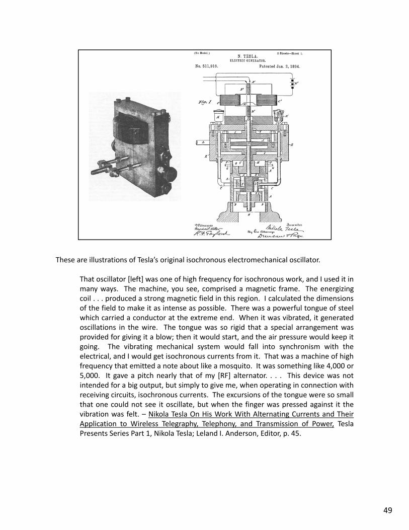
These are illustrations of Tesla’s original isochronous electromechanical oscillator.
That oscillator [left] was one of high frequency for isochronous work, and I used it inmany ways. The machine, you see, comprised a magnetic frame. The energizingcoil . . . produced a strong magnetic field in this region. I calculated the dimensionsof the field to make it as intense as possible. There was a powerful tongue of steelwhich carried a conductor at the extreme end. When it was vibrated, it generatedoscillations in the wire The tongue was so rigid that a special arrangement wasoscillations in the wire. The tongue was so rigid that a special arrangement wasprovided for giving it a blow; then it would start, and the air pressure would keep itgoing. The vibrating mechanical system would fall into synchronism with theelectrical, and I would get isochronous currents from it. That was a machine of highfrequency that emitted a note about like a mosquito. It was something like 4,000 or5,000. It gave a pitch nearly that of my [RF] alternator. . . . This device was notintended for a big output, but simply to give me, when operating in connection withreceiving circuits, isochronous currents. The excursions of the tongue were so smallthat one could not see it oscillate, but when the finger was pressed against it thevibration was felt. – Nikola Tesla On His Work With Alternating Currents and TheirApplication to Wireless Telegraphy, Telephony, and Transmission of Power, TeslaPresents Series Part 1, Nikola Tesla; Leland I. Anderson, Editor, p. 45.
49

Another little known Tesla invention is the direct‐conversion heterodyne wirelesstelegraph receiver.
51

This is an example of a state‐of‐the‐art super heterodyne radio receiver, the front‐endcircuitry design of which can be traced back to Tesla’s “beat receptor.”
“The Icom IC‐R9500‐02 . . . features an Oven Control Crystal Oscillator to achieveimpressive ±0.05ppm frequency stability.“
52

Tesla’s beat receptor for radio‐telegraphy is a direct‐conversion heterodyne receiverconsisting of an isochronous electro‐mechanical local oscillator and a mixer. ReginaldFessenden also experimented with the heterodyne technique.– http://en.wikipedia.org/wiki/Beat_receptor
See also, Cohen, Samuel, Dr. Nikola Tesla and His Achievements, The ElectricalExperimenter, February 1917, “Unique Alternating Current Generator for Exciting Tesla'sEarly “Beat” Receptor Actuated by Compressed Air or Steam Which Vibrates a SpecialEarly Beat Receptor. Actuated by Compressed Air or Steam Which Vibrates a SpecialDiaphragm‐Coil.” – http://en.wikisource.org/wiki/Dr._Nikola_Tesla_and_His_Achievements
53

Tesla’s electro‐mechanical instrument for the measurement of frequency and phase ofalternating electric currents, the “tikker,” incorporated the stop‐motion principle ofstroboscopy.
55

Harold Eugene "Doc" Edgerton (April 6, 1903 – January 4, 1990) was a professor ofelectrical engineering at the Massachusetts Institute of Technology. He is largely creditedwith transforming the stroboscope from Tesla’s obscure laboratory instrument into acommon device.
Falling drop of milk, illuminated by using a strobe light, photographed by Harold E.Edgerton, c. 1938.
Credit: © The Harold E. Edgerton 1992 Trust– https://alum.mit.edu/pages/sliceofmit/2009/12/21/doc‐edgerton/
56

The Edgerton stroboscope is widely used for stop‐motion photography and other purposes.
57

The Stroboscopic Card is for calibrating the speed of rotation of record turntables in orderto assure accurate reproduction of musical pitch.
58

This is Tesla’s electro‐mechanical instrument for the measurement of frequency and phaseof alternating electric currents, popularly known as the “tikker.” It incorporates amechanical clockwork mechanism that turns, at a constant speed, a disk that is markedwith a side‐by‐side pattern of equally spaced lines. Frequency measurements are obtainedby connecting a gas‐discharge‐type light source to the apparatus under test andilluminating the rotating disk. The stop‐motion effect combined with knowledge of thespeed of rotation of the calibrated disk allows for calculation of the frequency. Phasedetermination might be achieved using two light sources and measuring the angulardetermination might be achieved using two light sources and measuring the angulardisplacement between a single line as it appears to the observer. – Nikola Tesla: LectureBefore the New York Academy of Sciences – April 6, 1897, pp. 61‐69.
59

In addition to the poly‐phase AC power system, Tesla is fairly well known for his work in theareas of radio control and robotics.
61

The arrival on Mars of the Pathfinder robotic planetary exploration vehicle with it'sdiminutive rover Sojourner on July 4, 1997 was a landmark event in the history of wirelessremote control. After nearly 100 years of development, a technology with roots in aninstrument of war had begun to fulfill what may be its greatest potential—helping mankindto establish a virtual presence on other worlds. For the first time ever, a person on Earthcould visit an object on a distant planet and by reaching out through the medium of radio,touch it.
This slide shows Curiosity, a car‐sized robotic rover now exploring Gale Crater on Mars aspart of NASA's Mars Science Laboratory mission (MSL). It was launched from CapeCanaveral on November 26, 2011 aboard the MSL spacecraft and successfully landed onAeolis Palus in Gale Crater on Mars on August 6, 2012, 05:17 UTC. The Bradbury Landingsite was less than 2.4 km from the center of the rover's touchdown target after a563,000,000 km journey. The rover's goals include: investigation of the Martian climateand geology; assessment of whether the selected field site inside Gale Crater has everoffered environmental conditions favorable for microbial life, including investigation of therole of water; and planetary habitability studies in preparation for future humanexploration. In December 2012, Curiosity's two‐year mission was extended indefinitely. InApril and early May 2013, Curiosity went into an autonomous operation mode forapproximately 25 days during Earth–Mars solar conjunction. During this time, the rovercontinued to monitor atmospheric and radiation data, but did not move on the Martiancontinued to monitor atmospheric and radiation data, but did not move on the Martiansurface. – http://en.wikipedia.org/wiki/Curiosity_(rover)
62

During wartime there was much research under way toward reducing the Teslaconcept of the guided weapon in various laboratories. . . . So far as I know, thecredit for the concept rests entirely with him. – Edwin H. Armstrong
The Tomahawk is an all‐weather submarine or ship‐launched land‐attack cruise missiledeployed by the U.S. Navy in 1983. It can self‐navigate to a target by comparing the terrainbeneath missile's flight path with a contour map stored in an onboard computer. Afterlaunch a solid propellant propels the missile until a small turbofan engine takes over forlaunch, a solid propellant propels the missile until a small turbofan engine takes over forthe cruise portion of flight. Tomahawk is a highly survivable weapon. Radar detection isdifficult because of the missile's small cross‐section and low altitude flight. Similarly,infrared detection is difficult because the turbofan engine emits little heat. Systemsinclude Global Positioning System (GPS) receiver; an upgrade of the optical Digital SceneMatching Area Correlation (DSMAC) system; Time of Arrival (TOA) control, and improved402 turbo engines. – http://www.fas.org/man/dod‐101/sys/smart/bgm‐109.htm
63

This propeller‐driven radio controlled boat, designed and built by Tesla in 1898, is theoriginal prototype of all modern‐day uninhabited aerial vehicles (the UAV) and precisionguided weapons—in fact, all remotely operated vehicles—air, land or sea. Powered bylead‐acid batteries and an electric drive motor, the vessel was designed to be maneuveredalongside a target using instructions received from a wireless remote‐controltransmitter. Once in position, a command would be sent to detonate an explosive chargecontained within the boat's forward compartment.
[Nikola Tesla Photograph Archive.]
64

The weapon's guidance system incorporated a secure communications link between thepilot's controller and the surface‐running torpedo in an effort to assure that control couldbe maintained even in the presence of electronic countermeasures.
65

Tesla work in the area of wireless remote control went hand in hand with a critical interestin secure wireless telecommunications.
66

An important feature of every system for wireless remote control is its immunity tointerference. In order to achieve this Tesla developed a method for selectively activatingthe vehicle's wireless receiver. He called this "the art of individualization." In its most basicform he would transmit the control signals using only a single frequency. If greater securitywas needed, he used a wireless signal produced on a multiple of frequencies—thetransmitter worked at a number of separate wave lengths, like a pipe organ playing amusical chord or, alternatively, a specific sequence of notes. On the receiver side each oneof the individual frequency components had to be tuned in in order for the controlof the individual frequency components had to be tuned in, in order for the controlcircuitry to respond. These are the basic principles of the frequency‐division multiplexingand frequency‐hopping spread spectrum techniques for secure wirelesstelecommunications. – U.S. Patent No. 723,188, METHOD OF SIGNALING, March 17, 1903,application filed July 16, 1900, and U.S. Patent No. 725,605, "SYSTEM OF SIGNALING, April14, 1903, application filed July 16, 1900.
67

It’s a little known fact that Tesla is the acknowledged inventor of the electronic logic gatecircuit, a critical element of every digital computer.
68

The 1903 "System of Signaling" and "Method of Signaling“ patents explain more than theb i i i l f f h i d f di i i l i l i dbasic principles of frequency‐hopping and frequency‐division multiplexing spread spectrumtechniques for secure wireless telecommunications. They also describe the electronic AND‐gate logic circuit, a fundamental element of all present day digital computers.
In the mid 1890s Tesla's work was focused on the development of an independentremotely‐controlled device—the "telautomaton." These efforts led him to devise methodsfor selectively activating any of several wireless receivers that involved multipletransmissions on separate frequencies At the receiving end each one of the individualtransmissions on separate frequencies. At the receiving end, each one of the individualfrequency components had to be tuned in, in order for the receiver to respond—the ANDlogic function. In 1899 Tesla established an experimental station at Colorado Springs wherehe continued his studies. Realizing the importance of his ground‐breaking techniques hegave instructions upon his return to New York that patent applications be prepared andsubmitted. During the review period, the Patent Office told Tesla that another patentapplication for a similar concept had been received from Reginald Fessenden, and in 1902 aU.S. Patent Interference investigation was conducted concerning Tesla's wirelessU.S. Patent Interference investigation was conducted concerning Tesla s wirelesscommunications system. In the end, Tesla's claims were supported and he was grantedprotection under the "System of Signaling" and "Method of Signaling" patents—bothdescribing the AND‐gate circuit.
After World War II when computer hardware manufacturers attempted to patent digitallogic gates in general, the U.S. Patent Office asserted Tesla's turn‐of‐the‐century priority intheir electrical implementation. These same patents describe essential features of thespread‐spectrum wireless communications techniques known as frequency‐hopping andfrequency‐division multiplexing.
69

This is a photograph of the “Spirit” super computer at Wright‐Patterson Air Force base. Inaddition to, perhaps, containing everything that anyone might possibly want to know aboutTesla’s work in the areas of mechanical and electrical engineering, its circuitry is rooted inone of his designs from 1900, the electronic logic gate.
This government computer is tasked with simulated experiments that are too risky to beundertaken by personnel. Calculating at 1,500 trillion calculations a second makes it the 7th
most powerful computer in the world Dubbed “Spirit ” this highly‐dense supercomputermost powerful computer in the world. Dubbed Spirit, this highly dense supercomputersits on 9,000 square feet and weighs more than 30 tons. The price tag is $25 million. Aspecialized water‐circulation system was created to cool the computer off and preventover‐heating in the thousands of miles of copper wiring that encompasses its fiber opticcables. Spirit tests weapons systems, simulates bomb detonations and projects how cargoin aircraft can be parachuted to land where necessary and safely. Scientific research is alsoa function of Spirit, with a focus on everything from subatomic particles to hurricaneforecasting.
70

71

This photo accompanies a case history published by a manufacturer of the Tesla disk pump.
The UK paper industry's first DiscFlo pump has reduced downtime in pumping paperstock to almost zero and has cut machine downtime by 12 hours a month, whichyields savings of approximately $150,000 a year. The paper stock, which includesrecycled deinked stock, is around 4% consistency and contains 5‐7% entrained air.The pump feeds stock to the paper machine and if it fails, the entire paper machinegoes down The previous pump a centrifugal type commonly used for stockgoes down. The previous pump, a centrifugal type commonly used for stockpumping, suffered frequent breakdown and cavitations problems, due to the highlevel of entrained air. The mill engineering manager is delighted with the discpump's performance: “Since start up, the DiscFlo pump has performed 100%.”
72

The Tesla disk pump‐blower design has gained some acceptance by industry for specializedapplications where it is necessary to move viscous fluids and those containing solids. Inaddition, due to an absence of lifting surfaces, i.e., blades or impellers, its decreasedsusceptibility to impingement‐related corrosion and internal cavitations allows it to betterhandle abrasive‐containing fluids and two‐phase flows, such as boiling water. – U.S. PatentNo. 1,061,142, FLUID PROPULSION, May 6, 1913, application filed October 21, 1909.
73

This is a miniaturized Tesla turbo generator, prototyped for the U.S. Navy by C. R. Possellaround 1954. It consists of a two stage disk compressor, a one‐inch disk turbine and a twopole 180‐watt generator, all mounted on a common shaft.
74

While a number of researchers have investigated the design, the Tesla disk turbine is notreadily available for use by the public. – U.S. Patent No. 1.061,206, TURBINE, May 6, 1913,original application filed October 21, 1909; divided and this application filed January 17,1911.
75

In 1892 Tesla wrote,
Ere many generations pass, our machinery will be driven by a power obtainable atany point of the universe. This idea is not novel. Men have been led to it long agoby instinct or reason. It has been expressed in many ways, and in many places, inthe history of old and new. We find it in the delightful myth of Antheus, whoderives power from the earth; we find it among the subtle speculations of one ofyour splendid mathematicians and in many hints and statements of thinkers of theyour splendid mathematicians, and in many hints and statements of thinkers of thepresent time. Throughout space there is energy. Is this energy static or kinetic? Ifstatic our hopes are in vain; if kinetic—and this we know it is, for certain—then it isa mere question of time when men will succeed in attaching their machinery to thevery wheelwork of nature. Of all, living or dead, Crookes came nearest to doing it.His radiometer will turn in the light of day and in the darkness of the night; it willturn everywhere where there is heat, and heat is everywhere. But, unfortunately,this beautiful little machine, while it goes down to posterity as the most interesting,must likewise be put on record as the most inefficient machine ever invented! –Experiments with Alternate Currents of High Potential and High Frequency, IEEAddress, London, February 1892.
77

78

Tesla recognized that Crooks’ radiometer held little promise as a device for extractingsignificant energy from the “ambient medium.” He was far more optimistic about thepossibility of hot dry rock geothermal electric power generation.
"It is a well‐known fact that the interior portions of the globe are very hot, thetemperature rising, as observations show, with the approach to the center at therate of approximately 1deg C. for every hundred feet of depth.” – The Problem ofIncreasing Human Energy 1901Increasing Human Energy, 1901.
"All that is necessary to open up unlimited resources of power throughout theworld is to find some economic and speedy way of sinking deep shafts.“ – OurFuture Motive Power, 1931.
79
80

POSSIBILITY OF A "SELF‐ACTING" ENGINE OR MACHINE CAPABLE OF DERIVINGENERGY FROM THE MEDIUM—THE IDEAL WAY OF OBTAINING MOTIVE POWER.
“When I began the investigation of the subject under consideration . . . a survey ofthe various ways of utilizing the energy of the medium convinced me . . . That toarrive at a thoroughly satisfactory practical solution a radical departure from themethods then known had to be made. The windmill, the solar engine, the enginedriven by terrestrial heat, had their limitations in the amount of power obtainable. .. . There was enough heat‐energy in the medium, but only a small part of it wasavailable for the operation of an engine in the ways then known. . . . The problemwas to discover some new method which would make it possible both to utilizemore of the heat energy of the medium and also to draw it away from the same at amore rapid rate. . . .
“Evidently a living being could do this very thing, and since the experiences of myearly life had convinced me that a living being is a "self‐acting‐engine " Iearly life . . . had convinced me that a living being is . . . a self acting engine, Icame to the conclusion that it was possible to construct a machine which would dothe same. . . . I finally conceived a combination of apparatus which should makepossible the obtaining of power from the medium by a process of continuouscooling of atmospheric air. . . . In the process . . . there were five essential elementsin combination. . . .
“ h h l ll h f l f h b d h“The mechanical oscillator was the first element of this combination, and havingperfected this, I turned to the next, which was an air‐compressor of a design incertain respects resembling that of the mechanical oscillator. . . . At the close of1894 I had completed these two elements of the combination. . . . I was justbeginning work on the third element, which together with the first two would give arefrigerating machine of exceptional efficiency and simplicity, when a misfortunebefell me in the burning of my laboratory, which crippled my labors and delayed me.g y y, pp y y
“Much of this task on which I have labored so long remains to be done. A numberof mechanical details are still to be perfected and some difficulties of a differentnature to be mastered, and I cannot hope to produce a self‐acting machine derivingenergy from the ambient medium for a long time yet, even if all my expectationsshould materialize. Many circumstances have occurred which have retarded my
k f l t b t f l th d l b fi i lwork of late, but for several reasons the delay was beneficial.
“One of these reasons was that I had ample time to consider what the ultimatepossibilities of this development might be. I worked for a long time fully convincedthat the practical realization of this method of obtaining energy from the sun wouldbe of incalculable industrial value, but the continued study of the subject revealedthe fact that while it will be commercially profitable if my expectations are welly p y pfounded, it will not be so to an extraordinary degree.” – The Problem of IncreasingHuman Energy, 1901.
81

82

In 1932 Tesla stated, “All of my investigations seem to point to the conclusion that [cosmicrays] are small particles, each carrying so small a charge that we are justified in calling themneutrons ” – Tesla Cosmic Ray Motor May Transmit Power 'Round Earth Brooklyn Eagleneutrons. – Tesla Cosmic Ray Motor May Transmit Power Round Earth, Brooklyn Eagle,July 10, 1932.
Writing about radioactivity and radioactive materials a few months later Tesla said,“According to experimental findings and deductions of positive science, any materialsubstance (cooled down to the absolute zero of temperature) should be devoid of aninternal movement and energy. . . . I was struck by the thought that if there is energy withinthe substance it can only come from without. . . . I expressed it in the following axiom:"There is no energy in matter except that absorbed from the medium." . . . If all energy issupplied to matter from without then this all important function must be performed by themedium.
Tesla further wrote, “When radio‐active rays were discovered their investigators believedthem to be due to liberation of atomic energy in the form of waves This being impossiblethem to be due to liberation of atomic energy in the form of waves. This being impossiblein the light of the preceding I concluded that [radio‐active rays] were produced by someexternal disturbance and composed of electrified particles. . . . Suppose that bullets arefired against a wall. Where a missile strikes the material is crushed and spatters in alldirections radial from the place of impact. In this example it is perfectly clear that theenergy of the flying pieces can only be derived from that of the bullets. But inmanifestation of radio‐activity no such proof could be advanced and it was, therefore, ofh f d ll h f h lthe first importance to demonstrate experimentally the existence of this miraculousdisturbance in the medium. I was rewarded in these efforts with quick success largelybecause of the efficient method I adopted which consisted in deriving from a great mass ofair, ionized by the disturbance, a current, storing its energy in a condenser and dischargingthe same through an indicating device.” – The Eternal Source of Energy of the Universe,Origin and Intensity of Cosmic Rays, October 13, 1932, New York, reprinted in Tesliana,Special Edition, Belgrade, Yugoslavia, 1995, p. 56 ‐ 59.p , g , g , , p
In 1933 a reporter with the Philadelphia Public Ledger wrote of Tesla’s work, "Thisprinciple, which taps a source of power described as "everywhere present in unlimitedquantities" and which may be transmitted by wire or wireless from central plants to anypart of the globe, will eliminate the need of coal, oil, gas or any other of the commonfuels.“ – Tesla 'Harnesses' Cosmic Energy, Philadelphia Public Ledger, November 2, 1933.
Taken together these words suggest that in tapping a source described as “everywherepresent in unlimited quantities” Tesla was speaking of the liberation of atomic energy fromradioactive material, possibly by the process of static accumulation, and in writing about"central plants" the reporter is referring to nuclear power plants of a novel design basedupon Tesla's research from which energy would be distributed in the form of electricity.
83

The Static Accumulation nuclear battery (left) was developed in the early 1950’s by Linder,Rappaport and Loferski. Using a radioactive source of.25 Ci Sr‐90 (located at K) the devicedeveloped a DC potential of 365 kV at about 1 nA, for a continuous power output of about0.2 mW. D is an electrical insulator. Chamber C is evacuated.
Tesla’s description of his initial demonstration experiments suggests that he may have beendoing something along the same lines as the 1950’s static accumulation nuclear battery.
I was rewarded in these efforts with quick success largely because of the efficientmethod I adopted which consisted in deriving from a great mass of air, ionized bythe disturbance, a current, storing its energy in a condenser and discharging thesame through an indicating device.
It is assumed from the phrase, “rewarded with quick success” that no sophisticatedapparatus was required. The phrase, “consisted in deriving from a great mass of air”brings to mind Tesla’s disk blower, and an electrostatic generator (right) designed for the1935 particle beam projector and disclosed in The New Art of Projecting ConcentratedNon‐dispersive Energy Through Natural Media – System of Particle Acceleration for Use inNational Defense. It may be the two designs have some features in common.
Perhaps there are documents at the Nikola Tesla Museum in Belgrade that might shedPerhaps there are documents at the Nikola Tesla Museum in Belgrade that might shedsome light on this obscure subject.
84
Another invention that has yet to enter into the public domain is Tesla’s advanced systemfor the wireless transmission of electrical energy.
In this section we will learn more about the Tesla coil and then look beyond theconvenience of induction coil charging pads to describe and possibly expand upon Tesla’sworld‐wireless vision.
85
The Tesla coil is intended for radio‐frequency (RF) power processing.
87

This WiTricity induction coil charging pad is a minor fulfillment of Tesla’s wireless vision.
88
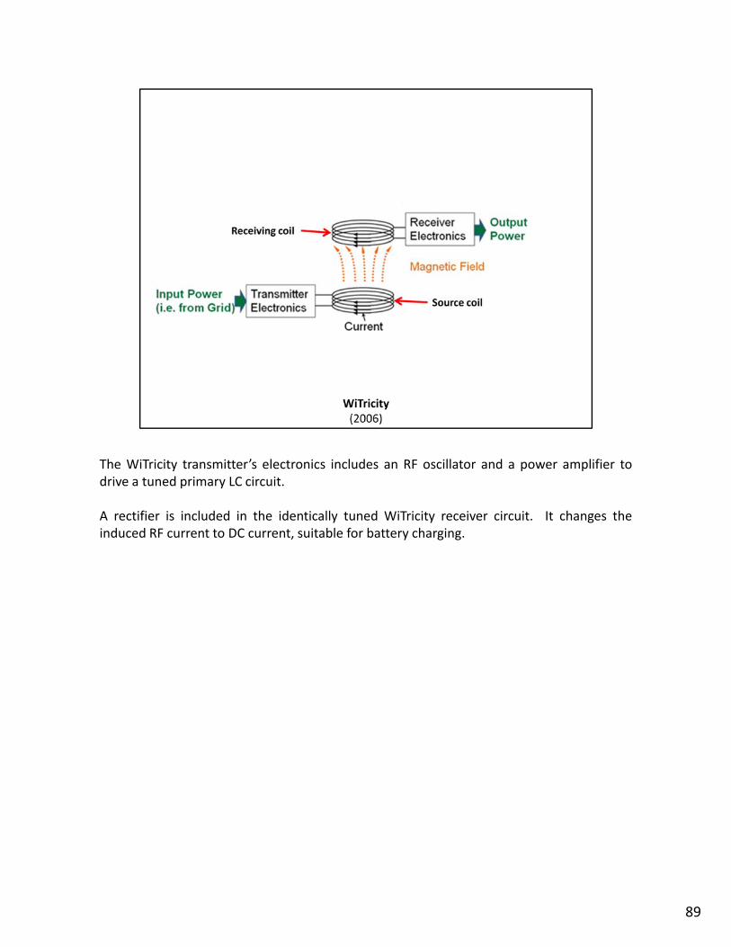
The WiTricity transmitter’s electronics includes an RF oscillator and a power amplifier todrive a tuned primary LC circuit.
A rectifier is included in the identically tuned WiTricity receiver circuit. It changes theinduced RF current to DC current, suitable for battery charging.
89

The same apparatus was constructed by Tesla, as seen in this drawing from his 1898 lectureHigh Frequency Oscillators for Electro‐therapeutic and Other Purposes.
G is a special high‐frequency alternator designed for the specific purpose of driving a tunedTesla coil primary LC circuit.
Inductor P (L) and capacitor C (C) constitute the tuned primary “LC circuit.” Secondaryinductor S is the “receiving coil ” The inset shows a mechanical rectifier and a mechanicalinductor S is the receiving coil. The inset shows a mechanical rectifier and a mechanicalpulse‐width modulator, both designed by Tesla in 1899.
91

When it is desired to use small currents of high tension, a secondary coil is resortedto, as illustrated in Fig. 2. I have found it from the outset convenient to make adeparture from the ordinary ways of winding the coils with a considerable numberdeparture from the ordinary ways of winding the coils with a considerable numberof small turns. For many reasons the physician will find it better to provide a largehoop H of not less than, say three feet in diameter and preferably more, and towind upon it a few turns of stout cable P. The secondary coil S is easily prepared bytaking two wooden hoops h h and joining them with stiff cardboard. One singlelayer of ordinary magnet wire, and not too thin at that, will be generally sufficient,the number of turns necessary for the particular use for which the coil is intendedbeing easily ascertained by a few trials. Two plates of large surface, forming anadjustable condenser, may be used for the purpose of synchronizing thesecondary with the primary circuit, but this is generally not necessary. In thismanner a cheap coil is obtained, and one which cannot be easily injured. Additionaladvantages, however, will be found in the perfect regulation which is effectedmerely by altering the distance between the primary and secondary, for whichadjustment provision should be made and furthermore in the occurrence ofadjustment provision should be made, and, furthermore, in the occurrence ofharmonics which are more pronounced in such large coils of thick wire, situated atsome distance from the primary. – High Frequency Oscillators for Electro‐therapeutic and Other Purposes, Electrical Engineer, November 17, 1898.
90

Computer Science undergrad and writer Shashank Bhardwaj came up with this fancifulillustration of Witricity.
[Bhardwaj, Shashank, The Future of Wireless Charging, Geek Insider, March 15, 2013;www.geekinsider.com/the‐future‐of‐wireless‐charging/]
92

This is Tesla’s own WiTricity setup, constructed more than 120 years ago as a scientific tooland used to entertain visitors at his South 5th Avenue laboratory.
The “WiTricity Source Coil” is labeled P for “primary.” Instead of being a small coil of wiresitting on an end table, it consists of a single electrical cable that, “passes all around thehall.”
Multiple WiTricity “Receiving Coils” are labeled S for “secondary”Multiple WiTricity Receiving Coils are labeled S for secondary.
93

This is a “coil table” WiTricity secondary receiver with an incandescent electric lampattached.
The wireless connection to the surrounding primary cable is by electromagnetic induction.
94

This slide shows another secondary coil table with sparks jumping between two verticalmetal plates mounted on top of it. It’s also known as a “tuning table.”
A few experiments performed in Mr. Tesla's laboratory work shop afford an idea ofthe flexibility of the methods by which powerful electrostatic effects are producedacross many feet of intervening space. The workshop is a room about forty byeighty feet, and ten or twelve feet high. A circuit of small cable is carried around itfrom the terminals of the oscillator In the center of the clear open space is placedfrom the terminals of the oscillator. In the center of the clear, open space is placeda coil, wound drum fashion, three or four feet high, and unconnected with thecurrent source save through the medium of the atmosphere. The coil is provided,as shown in the picture, with two condenser plates for adjustment, standing up likecymbals. The plates act after the manner of a spring, and the coil is comparable toan electromagnetic weight. The system of apparatus in the middle of the room hastherefore a certain period of vibration, just as though it were a tuning‐fork, or asheet of thin resonant glass. Around the room, over the cable, there are sent fromthe oscillator electrical current vibrations. By carefully adjusting the condenserplates so that the periodicity or swing of the induced current is brought into stepwith that of the cable currents, powerful sparks are made to pour across betweenthe plates in the dense streams shown in Fig. 9. In this manner it is easy to reachtensions as high as 200,000 and 300,000 volts. – Tesla's Oscillator and OtherInventions, Century Illustrated Magazine, April 1895.Inventions, Century Illustrated Magazine, April 1895.
95

The circuit connections as usually made are illustrated schematically. . . . Thecondensers C C, connected in series, are preferably charged by a step‐uptransformer but a high frequency alternator static machine or a direct currenttransformer, but a. high frequency alternator, static machine, or a direct currentgenerator, if it be of sufficiently high tension to enable the use of small condensers,may be used with more or less success. The primary p, through which the highfrequency discharges of the condensers are passed, consists of very few turns ofcable of as low resistance as possible, and the secondary s, preferably at somedistance from the primary to facilitate free oscillation, has one of its ends‐‐that isthe one which is nearer to the primary‐‐connected to the ground, while the otherend leads to an insulated terminal T. . . . It is of importance in this case to establishsynchronism between the oscillations in the primary and secondary circuits p and srespectively. This will be as a rule best effected by varying the self‐induction of thecircuit including the primary loop or coil p, for which purpose an adjustable self‐induction e is provided. . . .
The primary and secondary oscillations being in close synchronism the points ofThe primary and secondary oscillations being in close synchronism, the points ofhighest potential will be on a part of terminal T, and the consumption of energy willoccur chiefly there. . . . The synchronism being perfect and the length of thesecondary coil just equal to one‐quarter of the wave length, these points will beexactly on the free end of terminal T, that is, the one situated farthest from the endof the wire attached to the terminal. If this be so and if now the period of theoscillations in the primary be shortened, the points of highest potential will recede
d h d l h l h d d d htowards the secondary coil, since the wave‐length is reduced and since theattachment of one end of the secondary coil to the ground determines the positionof the nodal points, that is, the points of least potential. Thus, by varying the periodof vibration of the primary circuit in any manner, the points of highest potential maybe shifted accordingly along the terminal T, which has been shown, designedly, longto illustrate this feature. – High Frequency Oscillators for Electro‐therapeutic andOther Purposes, Electrical Engineer, November 17, 1898.p , g , ,
96

In the previous slides the inductive coupling between the primary and the secondary coilsis quite loose.
With the tighter coupling shown here the transfer of energy into the secondary is moreefficient; more energy is extracted from the primary circuit during each cycle.
Ideally, all of the available energy is taken out of the primary LC circuit and put into thesecondary circuit in a single cycle or less but this is difficult to achieve with the two coilsecondary circuit in a single cycle or less, but this is difficult to achieve with the two coilconfiguration.
Here is our first example a Tesla coil secondary configured as a one‐quarter wavelengthhelical resonator. The end closest to the primary is grounded and the coil’s opposite end isconnected to a terminal capacitance or isotropic capacitance; the “top‐load” in Tesla coilbuilder’s jargon.
The slow wave helical resonator was a major engineering breakthrough in radio‐frequencypower processing that has yet to achieve its full potential in terms of applied technology.
97

This an early conical Tesla coil helix slow‐wave VSWR resonator structure at the South 5thAvenue laboratory, circa 1895.
Notice the primary cable fastened to struts projecting down from ceiling. A power supplytransformer and capacitor banks can also be seen.
This illustrates the first step in the evolution of the magnifying transmitter.
98

Here’s a photo of a three coil magnifier system taken at the Houston Street laboratory, circa1896.
A two turn primary cable is wound on a wooden frame hidden behind the flat spiralsecondary.
The coil in the foreground from which streamers are issuing is called the “extra coil.”
[Nikola Tesla Photograph Archive.]
99

Here Tesla describes the operation of his oscillator as used to investigate methods offrequency‐division multiplexing.
Referring to the apparatus which I often employed for convenience in practicing theinvention, the transmitter comprised a high tension transformer, giving about 50kilovolts pressure, which charged several sets of condensers. These condenserswere automatically discharged so that a number of oscillations, two, three or more,in extremely rapid succession were passed through a cable laid around the room.When I used arrangements of circuits, such as illustrated in my patents on thetransmission of energy, I most frequently directed the oscillatory discharges of thecondensers through primaries placed in inductive relation to the circuits which weregrounded or, generally speaking, connected to the medium which served as ameans of transmission, which in some cases was wire. . . .
This coil I excited by a primary so proportioned that when the latter was closed bythe make‐and‐break disk which discharged the condensers the oscillation in thethe make and break disk which discharged the condensers, the oscillation in thesecondary was quickened to much above the rate which the secondary or spiral coilvibrated when the primary was opened. In this way I obtained two oscillations,which I regulated and controlled in a number of ways, and by means of which Iexcited two tuned circuits, each adjusted to respond to one of the oscillations whichwere impressed upon the ground in rapid succession by the transmitting coildescribed. . . .
The primary was wound on a wooden frame and comprised two turns of very heavycable. The coil to which I refer was placed on rollers so that it could be put at anydesired distance from the exciting primary, in this way permitting me go graduatethe effects and to produce the two vibrations required. . . .
It was in regular use for a number of years prior to my going to Colorado, havingg y p y g g , gbeen constructed, if I remember rightly, sometime in 1895, but it was not used inthe manner described to produce two oscillations until a much later date, I thinksometime in 1898. – Nikola Tesla: Guided Weapons & Computer Technology, TeslaPresents Series Part 3, Nikola Tesla, et al; Leland I. Anderson, Editor, 21st CenturyBooks, 1998, pp. 10 – 13.
100
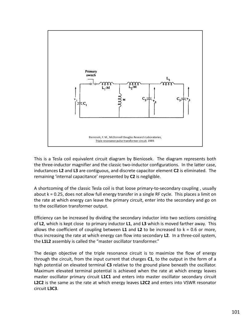
This is a Tesla coil equivalent circuit diagram by Bieniosek. The diagram represents boththe three‐inductor magnifier and the classic two‐inductor configurations. In the latter case,inductances L2 and L3 are contiguous, and discrete capacitor element C2 is eliminated. Theremaining ‘internal capacitance’ represented by C2 is negligible.
A shortcoming of the classic Tesla coil is that loose primary‐to‐secondary coupling , usuallyabout k = 0.25, does not allow full energy transfer in a single RF cycle. This places a limit onthe rate at which energy can leave the primary circuit enter into the secondary and go onthe rate at which energy can leave the primary circuit, enter into the secondary and go onto the oscillation transformer output.
Efficiency can be increased by dividing the secondary inductor into two sections consistingof L2, which is kept close to primary inductor L1, and L3 which is moved farther away. Thisallows the coefficient of coupling between L1 and L2 to be increased to k = 0.6 or more,thus increasing the rate at which energy can flow into secondary L2. In a three‐coil system,the L1L2 assembly is called the “master oscillator transformer.”
The design objective of the triple resonance circuit is to maximize the flow of energythrough the circuit, from the input current that charges C1, to the output in the form of ahigh potential on elevated terminal C3 relative to the ground plane beneath the oscillator.Maximum elevated terminal potential is achieved when the rate at which energy leavesmaster oscillator primary circuit L1C1 and enters into master oscillator secondary circuitmaster oscillator primary circuit L1C1 and enters into master oscillator secondary circuitL2C2 is the same as the rate at which energy leaves L2C2 and enters into VSWR resonatorcircuit L3C3.
101

At the Colorado Springs Experimental Station Tesla tested various concepts in preparationfor the construction of Wardenclyffe, that was planned as the first station in a worldwidenetwork of wireless telecommunications facilities.
In Colorado I erected a plant for the practical purpose of arriving at accurate datafor the construction of a large plant which I have termed a universal relay, or somesuch words. The plant in Colorado was merely designed in the same sense as anaval constructor designs first a small model to ascertain all the quantities beforenaval constructor designs first a small model to ascertain all the quantities beforehe embarks on the construction of a big vessel. I had already planned most of thedetails of the commercial plant, subsequently put up at Long Island, except that atthat time the location was not settled upon. The Colorado plant I have used indetermining the construction of the various parts, and the experiments which werecarried on there were for the practical purpose of enabling me to design thetransmitters and receivers which I was to employ in the large commercial plantsubsequently erected. – Nikola Tesla On His Work with Alternating Currents andTheir Application to wireless Telegraphy, Telephony, and Transmission of Power, p.170.
In this drawing of the Colorado Springs magnifying transmitter the primary circuit L1C1 hasbeen omitted for the sake of simplicity. The accompanying text in the Colorado SpringsNotes reads, “In all cases it has been found important to have the two systems vibrate inNotes reads, In all cases it has been found important to have the two systems vibrate insynchronism.” The “two systems” are the secondary LC circuit and the extra coil plus theelevated air terminal.
102

This is the Colorado Springs Magnifying Transmitter of 1899.
The three‐coil oscillator design allows tighter inductive coupling and more rapid energytransfer between the primary and secondary. With the k = 0.6, transient, lumped coupledexcitation mode, full energy transfer takes place in exactly one cycle. With tighter couplingfull energy transfer can be achieved in less than one cycle. [Dr. James Corum]
The sparking Tesla coil incorporates a local ground plane This can be either a local groundThe sparking Tesla coil incorporates a local ground plane. This can be either a local groundconnection made up of buried wires or a ground rod driven near the base of the machine.Alternatively, a conducting surface, such as a large metal sheet or screen is positioneddirectly under the apparatus.
With the refined Tesla coil magnifying transmitter, on the other hand, close attention mustbe paid to electrical isolation of the ground terminal electrode from the oscillator in orderto avoid a partial ‘short‐circuit’ of the elevated terminal with the surrounding terrain.
[Nikola Tesla Photograph Archive.]
103

Tesla discovered a number of problems with the Colorado Springs magnifying transmitterdesign. The solutions for these are found in the 1914 patent “Apparatus for TransmittingElectrical Energy” and other patents applied for between 1900 and 1902.
The maximum elevated terminal potential is increased by the prevention of streamers. The1914 patent drawing shows an improved terminal that can be charged to a higher potentialthan previously possible. Tesla achieved this by modifying the earlier terminal’s smoothsurface with closely spaced hemispherical attachmentssurface with closely spaced hemispherical attachments.
Shown are the closely coupled primary C and secondary A of the master oscillatortransformer. The lower end of the tertiary or helix extra coil VSWR resonator is connectedto the upper end of the relatively low impedance secondary. The lower end of thetransformer secondary is connected to a substantial ground terminal set in the bulkcomposite material that is Earth. The upper end of the extra coil is connected to theelevated terminal insulated in space on non‐conducting supports.
104

An even more advanced elevated terminal than the 1902 version is revealed in 1935 in, TheNew Art of Projecting Concentrated Non‐dispersive Energy Through Natural Media –System of Particle Acceleration for Use in National Defense.
1) Spherical frame.2) Insulating bulb with an electrode of thin sheet metal suitably rounded and a
metallic socket.3) Nut fastener3) Nut fastener.
As will appear from the inspection of the drawing, the spherical frame of theterminal is equipped with devices, one of which is shown in the enlarged viewbelow and comprises a bulb 2, of glass or other insulating material and an electrodeof thin sheet suitable rounded. The latter is joined by a supporting wire to ametallic socket adapted for fastening to the frame 1, by means of nut 3. The bulb isexhausted to the very highest vacuum obtainable and the electrode can be chargedto an immense density. Thus, it is made possible to raise the potential of theterminal to any value desired, so to speak, without limit, and the usual losses areavoided. I am confident that as much as one hundred million volts will be reachedwith such a transmitter providing a tool on inestimable value for practical purposesas well as scientific research.
105

Another area of investigation directed toward perfection of the magnifying transmitterdesign was the oscillator‐to‐earth ground terminal electrode. Shown here is a magnifyingtransmitter design dated May 19, 1901, placing it at Wardenclyffe.
Included are, L1, L2, C2, L3, C3. Notice how the master oscillator secondary capacitor C2and the ground terminal electrode are placed together as a single unit.
In many instances when working with an oscillatory system transmitting itsIn many instances when working with an oscillatory system transmitting itsvibrations upon the ground I observed that the effects produced were strongerwhen the oscillating system was connected to earth through a condenser. Thismay have been due to some secondary causes but theoretically there are reasonsfor expecting such a result. — Nikola Tesla ‐ From Colorado to Long Island: ResearchNotes ‐ Colorado Springs 1899‐1900 ‐ New York 1900‐1901.
In fig. C the most effective plan is illustrated. Here the secondary is joined to thecondenser [C2]. – Nikola Tesla ‐ From Colorado to Long Island: Research Notes ‐Colorado Springs 1899‐1900 ‐ New York 1900‐1901.
106

As best we can tell, this is the basic Tesla magnifying transmitter schematic. Shown are theearth terminal electrode assembly and also the legendary Wardenclyffe tunnels.
According to George Scherff the brick‐lined passages starting at the bottom of the 120‐footdeep vertical and curving up to the surface are for ground water drainage. They serve tokeep the earth around the tower dry, thus reducing capacitive coupling of the elevatedterminal with the surrounding terrestrial ground plane and mitigating as much as possiblethe partial short circuitthe partial short circuit..
In the well were four stone‐lined tunnels, each of which gradually rose back to thesurface. Large enough for a man to crawl through, they emerged like isolated,igloo‐shaped brick ovens three hundred feet from the base of the tower. – Seifer,Marc, Wizard : The Life and Times of Nikola Tesla, Chapter 33, p. 291.
Mr. Scherff, the private secretary of the inventor, told an inquirer that thecompanionway led to a small drainage passage built for the purpose of keeping theground about the tower dry. – Cloudborn Electric Wavelets To Encircle the Globe,New York Times, March 27, 1904.
A sump pump is placed into continuous operation for the water drainage system to beeffective. C2 is oil filled; the upper seal is not shown.effective. C2 is oil filled; the upper seal is not shown.
107

You see the underground work is one of the most expensive parts of the tower. Inthis system that I have invented it is necessary for the machine to get a grip of theearth otherwise it cannot shake the earth It has to have a grip on the earth so thatearth, otherwise it cannot shake the earth. It has to have a grip on the earth so thatthe whole of this globe can quiver, and to do that it is necessary to carry out a veryexpensive construction. I had in fact invented special machines. But I want to saythis underground work belongs to the tower.
There was, as your Honor states, a big shaft about ten by twelve feet goes downabout one hundred and twenty feet and this was first covered with timber and theinside with steel and in the center of this there was a winding stairs going down andin the center of the stairs there was a big shaft again through which the current wasto pass, and this shaft was so figured in order to tell exactly where the nodal pointis, so that I could calculate every point of distance. For instance I could calculateexactly the size of the earth or the diameter of the earth and measure it exactlywithin four feet with that machine.
And then the real expensive work was to connect that central part with the earth,and there I had special machines rigged up which would push the iron pipe, onelength after another, and I pushed these iron pipes, I think sixteen of them, threehundred feet, and then the current through these pipes takes hold of the earth.Now that was a very expensive part of the work, but it does not show on the tower,but it belongs to the tower.
By Mr. Fordham :Q. Was the hole really one hundred and twenty feet deep, did you say?A. Yes, you see the ground water on that place is about one hundred and twentyfeet. We are above the ground water about one hundred and twenty feet. In thewell we struck water at about eighty feet.
By the Referee :Q. What you call the main water table?A. Yes the main well we struck at eighty feet, but there we had to go deeper.
– Nikola Tesla On His Work with Alternating Currents and Their Application towireless Telegraphy, Telephony, and Transmission of Power, pp. 203‐204.
108

Wardenclyffe was the first of two stations to be used for trans‐Atlantic wirelesstelecommunications, global broadcasting and small‐scale demonstrations of wirelesspower transmission. It was erected in 1901 at Wardenclyffe‐On‐Sound (now Shoreham) onLong Island, New York. Built entirely of wood, except for spar junction plates and the 55‐ton skeleton spheroid at the top, the tower was designed so that every piece of framingcould be taken out at any time and replaced if necessary.
A minimum of two Wardenclyffe‐type stations are required for a multi‐channelA minimum of two Wardenclyffe type stations are required for a multi channel,bidirectional full duplex World Wireless telecommunications system. The Long Islandprototype was to be followed by a second plant, probably on the west coast of Scotlandnear Glasgow. Both facilities were to include a magnifying transmitter of the design shownin APPARATUS FOR TRANSMITTING ELECTRICAL ENERGY, U.S. Patent 1,119,732, December1, 1914, application filed January 18, 1902.
[Nikola Tesla Photograph Archive.]
109

An electric current flowing through a conductor carries electrical energy. Earth is anelectrical conductor, nearly spherical in shape, insulated in space. It possesses an electriccharge relative to the upper atmosphere beginning at about 50 kilometers elevation.When a second body, directly adjacent to Earth, is charged and discharged in rapidsuccession this causes an equivalent variation of Earth's electrostatic charge resulting in thepassage of electric current through the ground.
The Tesla coil magnifying transmitter both the single and dual tower forms is an electricalThe Tesla coil magnifying transmitter, both the single and dual tower forms, is an electricalmachine specifically designed to create as large a displacement as possible of Earth'selectric charge. It does this by alternately charging and discharging the oscillator's elevatedterminal capacitance at a specific frequency, periodically altering the electrostatic charge ofthe earth, and consequently, with sufficient power, the pressure over its entire surface.
A connection to earth, either directly or through a condenser is essential. – TheDisturbing Influence of Solar Radiation On the Wireless Transmission of Energy,Electrical Review and Western Electrician, July 6, 1912.
The placement of a grounded Tesla coil receiver tuned to the same frequency as thetransmitter at another point on the surface results in the flow of electric current throughthe earth between the two, "while an equivalent electric displacement occurs in theatmosphere." This current can be used at the receiver to drive an electrical load, which inatmosphere. This current can be used at the receiver to drive an electrical load, which inthe case of an individual World Wireless telecommunications system receiver is a sensitivedevice using only a small amount of energy.
111

A pair of Tesla coils can be used to transmit and receive electrical energy using the earth asa conductor. The one‐wire with ground return electrical power transmission system shownhere relies on current flowing through a single elevated wire plus current flowing throughthe earth to complete the circuit.
112

The elevated wire can be replaced by an ionized path connecting the Tesla coil transmitterto the Tesla coil receiver. This drawing shows a demonstration of this principle for anexaminer with the U.S. Patent Office. 120 to 130 mmHg is the atmospheric pressurecorresponding to about 8 miles elevation.
I came to the conviction that it would be ultimately possible, without any elevatedantenna—with very small elevation—to break down the upper stratum of the airand transmit the current by conduction Having discovered that I establishedand transmit the current by conduction. Having discovered that, I establishedconditions under which I might operate in putting up a practical commercial plant.When the matter came up in the patents before the Examiner, I arranged thisexperiment for him in my Houston Street laboratory. I took a tube 50 feet long, inwhich I established conditions such as would exist in the atmosphere at a height ofabout 4 1/2 miles, a height which could be reached in a commercial enterprise,because we have mountains that are 5 miles high; and, furthermore, in themountainous regions we have often great water power, so that the project oftransmitting it, if the plan was rational, would be practicable. – Nikola Tesla On HisWork With Alternating Currents and Their Application to Wireless Telegraphy,Telephony, and Transmission of Power, p. 126.
113

This is the basic Tesla wireless system showing the individual ground and elevatedterminals. The circuit consists of an ionized path connecting a transmitter‐receiver stationto the upper atmosphere beginning at an elevation of five to eight miles, the upperatmosphere, and a second ionized path connecting the upper atmosphere back down to asecond transmitter‐receiver station. For lower power operation the paths connecting thetwo transmitter‐receiver stations to the upper atmosphere take the form displacementcurrent. In both cases, the return path is established through the earth.
The earth is 4,000 miles radius. Around this conducting earth is an atmosphere.The earth is a conductor; the atmosphere above is a conductor, only there is a littlestratum between the conducting atmosphere and the conducting earth which isinsulating. . . . Now, you realize right away that if you set up differences of potentialat one point, say, you will create in the media corresponding fluctuations ofpotential. But, since the distance from the earth's surface to the conductingatmosphere is minute, as compared with the distance of the receiver at 4,000miles, say, you can readily see that the energy cannot travel along this curve and getthere, but will be immediately transformed into conduction currents, and thesecurrents will travel like currents over a wire with a return. The energy will berecovered in the circuit, not by a beam that passes along this curve and is reflectedand absorbed, . . . but it will travel by conduction and will be recovered in this way.– Nikola Tesla On His Work With Alternating Currents and Their Application toNikola Tesla On His Work With Alternating Currents and Their Application toWireless Telegraphy, Telephony, and Transmission of Power, Leland I. Anderson,Editor, 21st Century Books, 1992, pp. 129‐130.
114

This is the basic earth‐resonance transmitter configuration as incorporated into the initialWardenclyffe design. To the right is a Tesla coil receiver. [Leland Anderson, “Rare Notesfrom Tesla on Wardenclyffe,” Electric Spacecraft, Issue 26, Apr/May/Jun 1997.]
I shall typically illustrate the manner of applying my discovery by describing one ofthe specific uses of the same ‐ namely, the transmission of intelligible signals ormessages between distant points For the present it will be sufficient to statemessages between distant points. . . . For the present it will be sufficient to statethat the planet behaves like a perfectly smooth or polished conductor ofinappreciable resistance with capacity and self induction uniformly distributed alongthe axis of symmetry of wave propagation and transmitting slow electricaloscillations without sensible distortion and attenuation. . . . The specific plan ofproducing the stationary waves, here‐in described, might be departed from. Forexample, the circuit which impresses the powerful oscillations upon the earthmight be connected to the latter at two points. . . . In collecting the energy ofthese disturbances in any terrestrial region at a distance from their source, for anypurpose and, more especially, in appreciable amounts, the most economical resultswill be generally secured by the employment of my synchronized receivingtransformer.” – ART OF TRANSMITTING ELECTRICAL ENERGY THROUGH THENATURAL MEDIUMS, Apr. 17, 1906, Canadian Patent No. 142,352, Aug. 13, 1912.
115

This is a similar earth‐resonance transmitter. In this case the two side‐by‐side synchronizedresonator structures are energized by separate power plants.
Now, it is quite certain that at any point within a certain radius of the source S aproperly adjusted self‐induction and capacity device can be set in action byresonance. But not only can this be done, but another source S1 . . . similar to S . . .can be set to work in synchronism with the latter, and the vibration thus intensifiedand spread over a large area – On Light and Other High Frequency Phenomenaand spread over a large area. . . . On Light and Other High Frequency Phenomena,Franklin Institute, Philadelphia and National Electric Light Association, St. Louis,1893.
The drawing is from Modern Mechanix, July 1934, “Radio Power will Revolutionize theWorld” as told by Tesla to Alfred Albelli. The illustration is captioned, “We are on thethreshold of a gigantic revolution, based on the commercialization of the wirelesstransmission of power.”
116
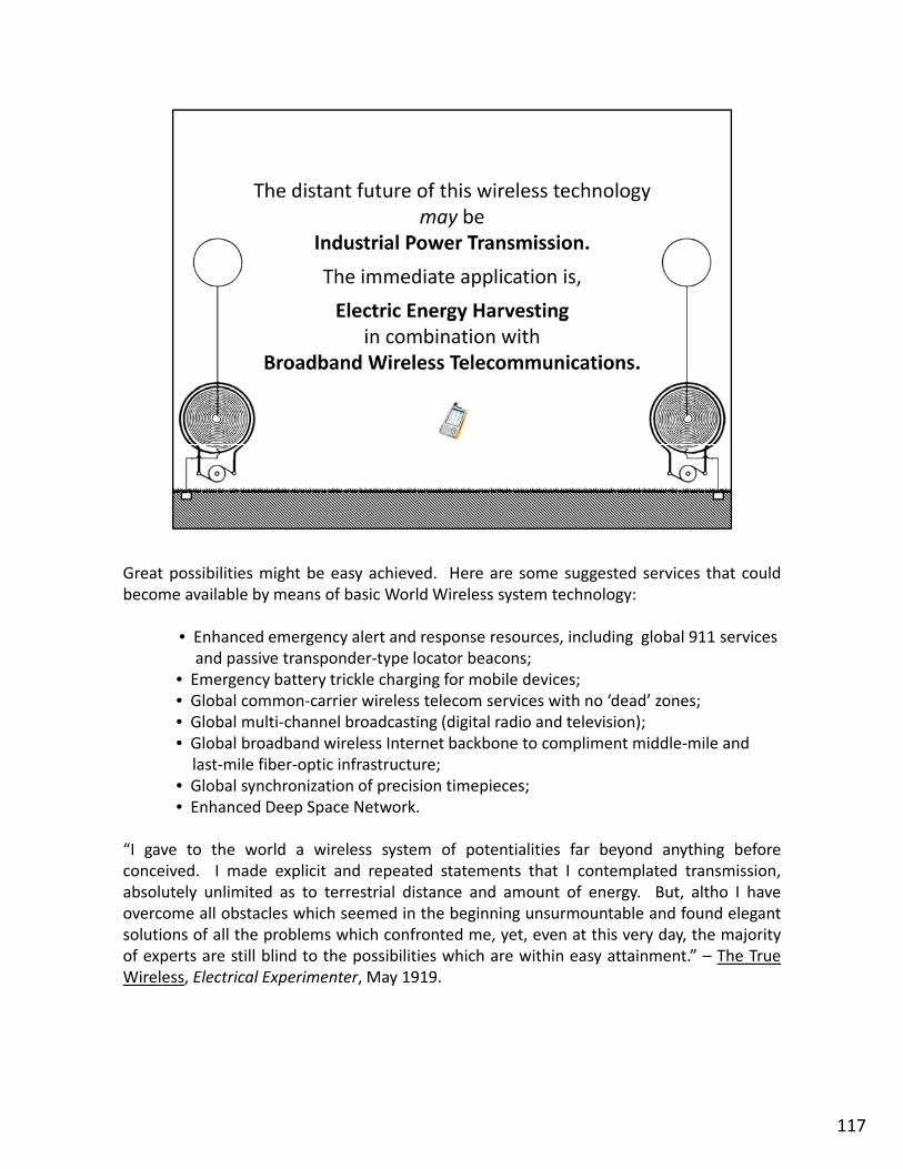
Great possibilities might be easy achieved. Here are some suggested services that couldbecome available by means of basic World Wireless system technology:
• Enhanced emergency alert and response resources, including global 911 services and passive transponder‐type locator beacons;
• Emergency battery trickle charging for mobile devices;• Global common‐carrier wireless telecom services with no ‘dead’ zones;• Global multi‐channel broadcasting (digital radio and television);Global multi channel broadcasting (digital radio and television);• Global broadband wireless Internet backbone to compliment middle‐mile and last‐mile fiber‐optic infrastructure;
• Global synchronization of precision timepieces;• Enhanced Deep Space Network.
“I gave to the world a wireless system of potentialities far beyond anything beforeconceived. I made explicit and repeated statements that I contemplated transmission,absolutely unlimited as to terrestrial distance and amount of energy. But, altho I haveovercome all obstacles which seemed in the beginning unsurmountable and found elegantsolutions of all the problems which confronted me, yet, even at this very day, the majorityof experts are still blind to the possibilities which are within easy attainment.” – The TrueWireless, Electrical Experimenter, May 1919.
117

Further development of the existing theoretical foundation supporting Tesla’s wirelesswork.
119

He goes on to say,
It is just like this: I have invented a knife. The knife can cut with the sharp edge. Itell the man who applies my invention, you must cut with the sharp edge. I knowperfectly well you can cut butter with the blunt edge, but my knife is not intendedfor this. You must not make the antenna give off 90 percent in electromagnetic and10 percent in current waves, because the electromagnetic waves are lost by thetime you are a few arcs around the planet while the current travels to thetime you are a few arcs around the planet, while the current travels to theuttermost distance of the globe and can be recovered.
He then mentions Arnold Sommerfeld.
This view, by the way, is now confirmed. Note, for instance, the mathematicaltreatise of Sommerfeld, who shows that my theory is correct, that I was right inmy explanations of the phenomena. . . .
– Nikola Tesla On His Work With Alternating Currents and Their Applicationto Wireless Telegraphy, Telephony, and Transmission of Power, p. 75
Arnold Sommerfeld described an electrodynamic wave that is guided along a wire of finiteconductivity and Jonathan Zenneck expanded upon this description, asserting that theearth's surface behaves in a manner similar to a conducting wire. This is the Sommerfeld‐earth s surface behaves in a manner similar to a conducting wire. This is the SommerfeldZenneck Surface Wave.
120

The free electron model is a simple model for the behavior of valence electrons in ametallic solid.
On the cosmological scale, non‐gaseous planets like Earth are spoken of as “metals.”
The free electron model was developed principally by Arnold Sommerfeld who combinedthe classical Drude model with quantum mechanical Fermi‐Dirac statistics and hence it isalso known as the Drude–Sommerfeld modelalso known as the Drude Sommerfeld model.– http://en.wikipedia.org/wiki/Free_electron_model
"Spherical Transmission Lines and Global Propagation, An Analysis of Tesla's ExperimentallyDetermined Propagation Model," K. L. Corum, J. F. Corum, Ph.D., and J. F. X. Daum, Ph.D.1996, p. 24, Appendix I. "Plasmons, Longitudinal Waves, and the World as an Electron Gas.“
121

The “conductor” can be either a ½ wavelength dipole in free space over the terrestrialground plane or the earth itself.
Bulk plasmons are associated with pure electromagnetic space waves, with the electric andmagnetic fields being modeled as perpendicular to the direction of propagation.
Surface plasmons are associated with longitudinal charge density waves along the earth‐atmosphere interface earth being a conductor and the lower atmosphere being aatmosphere interface, earth being a conductor and the lower atmosphere being adielectric.
122

A motivated student could easily invest their entire career toward an investigation of theconcepts represented here. There are researchers presently doing just this in the fields ofquantum physics, plasmonics and nano‐technology.
The bulk plasmon dispersion curve relates the time variation of the radiatingelectromagnetic space wave (given by its angular frequency ω) to the spatial variation ofthe wave (given by its wave vector kx). Bulk plasmons can only exist for ω > ωp, where ωp isthe plasma frequency the resonant frequency of free electrons or electron gas in responsethe plasma frequency, the resonant frequency of free electrons or electron gas in responseto an electrical excitation.
The surface plasmon dispersion curve relates the time‐variation of the electromagnetictransmission‐line wave (also given by its angular frequency ω) to the spatial variation of thewave (given by its wave vector kx). Surface plasmons exist for ω < ωp, in which the wave‐vector for bulk plasmons becomes imaginary. The electrical excitation gives rise to alongitudinal electron density wave along with a bound‐mode electromagnetic wave,decaying exponentially away from the conductor‐dielectric interface.
– Surface Plasmon Polaritons, Justin White, March 19, 2007 (Submitted as coursework for AP272, Stanford University, Winter 2007).– Introduction to Surface Plasmon Theory, Jean‐Jacques Greffet, Institut d’OptiqueGraduate School, ca. 2009.Graduate School, ca. 2009. – Nanophotonics lecture series, Prof. Albert Polman, Utrecht University, 2010‐2011, Class 2: “Surface plasmon polaritons.“
123

Zenneck waves may be excited by bombarding the surface with "fast electrons [Powel, C.J. and J.B. Swan, Physical Review, Vol. 118, 1960, p. 640]. This bears a striking resemblance to Tesla's experiments These plasma waves behave likestriking resemblance to Tesla s experiments. . . . These plasma waves behave like real surface waves. – "Spherical Transmission Lines and Global Propagation, An Analysis of Tesla's Experimentally Determined Propagation Model," K. L. Corum, J. F. Corum, Ph.D., and J. F. X. Daum, Ph.D. 1996, p. 24, Appendix I. "Plasmons, Longitudinal Waves, and the World as an Electron Gas."
While the Norton Surface Wave (excited by a vertical dipole in free space over a conductingground plane) is the result of electrical currents induced in the earth by refraction of aportion of the reflected‐wave component of the ground‐wave component of the spacewave at the earth‐atmosphere interface, the ‘Zenneck‐like’ surface wave associated withTesla's apparatus is the result of fast electron bombardment at each station resulting interrestrial current flowing between discrete points of electrical connection to the earth'ssubsurface.
124

Dr. Corum also writes,
There will exist the possibility of long‐range coulomb interactions, which engenderlongitudinal ‘compressional’ electric waves propagating over the surface of theearth and bear a striking similarity to the Zenneck waves propagating over thesurface of the earth. – Corum, J. F., et al, "Plasmons, Longitudinal Waves, and theWorld as an Electron Gas,” 1996.
With appropriate constitutive parameters, a pure Zenneck wave would seem tohold out the promise of guided propagation with no radiation field to waste energy.– Corum, K. L. and J. F. Corum, "Nikola Tesla, Lightning Observations and StationaryWaves," Appendix II, "The Zenneck Surface Wave,“ 1994.
125

Tesla’s approach is to employ longitudinal charge density waves while at the same timesuppressing electromagnetic radiation.
Tesla's claim that his system is different from Hertz‘s is based on the fact that at lowfrequencies, and with small antenna in terms of wavelength, radiation of Hertziantype electromagnetic wave is small. Tesla's waves, if we are allowed to use such aname, are in fact surface waves in modern terminology. . . . In "pure Hertzian" wave(in Tesla's terminology) there is no induced current in the Earth except on reflection(in Tesla s terminology) there is no induced current in the Earth, except on reflectionregion which is not essential for the discussion. In contrast to the latter, guidedsurface . . . waves do not exist without current in the Earth crust. Having this inmind, we can conclude that there is a truth in Tesla's statements about specificbehavior of low frequency, guided to the Earth waves. As regards correctness of hisapproach to the propagation theory based on outlined assumptions, more study isneeded and we hope that it will be done in the future. – Marinčić, Aleksandar,“Research of Nikola Tesla in Long Island Laboratory,” Energy and Development atthe International Scientific Conference in Honor of the 130th Anniversary of theBirth of Nikola Tesla, The Tesla Journal, Numbers 6 & 7, Tesla Memorial Society,1990, pp. 25‐28.
126

127


