Embed Size (px)
Citation preview

Purdue Hydrogen Systems Laboratory
J. Gore P. Ramachandran, P. Gagare
A. Varma, E. Shafirovich, V. Diakov, M. DiwanY. Zheng, A. Brockman, S. Basu
R. Kramer, P. Maness*, J. Peterson, B. Ting, L. Pelter
Purdue University*National Renewable Energy Laboratory
May 16, 2007STP22
This presentation does not contain any proprietary, confidential, or otherwise restricted information

2
Overview (storage)
• Start – September 2006• End – September 2007• 40% complete
• Barriers addressed– A. System weight and volume– J. Thermal management– R. Regeneration process
• TargetsBudget
• General Motors (lab infrastructure)• General Atomics (AB synthesis)
Partners
• $825,000– $660,000 (DOE)– $165,000 (Purdue)
• Funding received in FY06: $660,000
2007 2010 2015
Gravimetric capacity
kgH2/kg(wt%)
0.045(4.5%)
0.06(6%)
0.09(9%)
Volumetric capacity
kgH2/L 0.036 0.045 0.081
Timeline Barriers
3
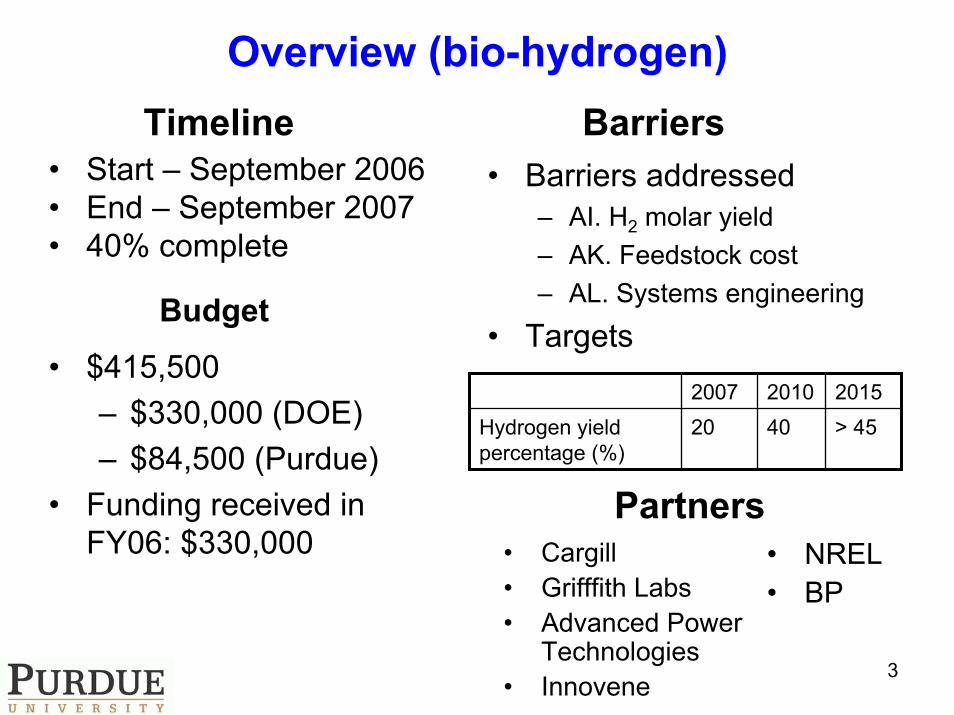
Overview (bio-hydrogen)
• Start – September 2006• End – September 2007• 40% complete
• Barriers addressed– AI. H2 molar yield– AK. Feedstock cost– AL. Systems engineering
• TargetsBudget
• Cargill• Grifffith Labs• Advanced Power
Technologies• Innovene
Partners
• $415,500– $330,000 (DOE)– $84,500 (Purdue)
• Funding received in FY06: $330,000
2007 2010 2015Hydrogen yield percentage (%)
20 40 > 45
Timeline Barriers
• NREL• BP

4
Outline
• Ammonia Borane-based Hydrogen Storage Methods
• Thermal Management of Recyclable Chemical Hydride Systems
• Bio-hydrogen Production from Organic Wastes

5
Objectives (Ammonia Borane-based Hydrogen Storage Methods)
• Improve the extent, rate and control of hydrogen release from ammonia borane (AB) by hydrolysis reactions
• Characterize the dehydrogenation products and develop new methods for AB regeneration
• Investigate a new method for hydrogen generation from water and ammonia boraneusing self-sustained combustion reactions
6
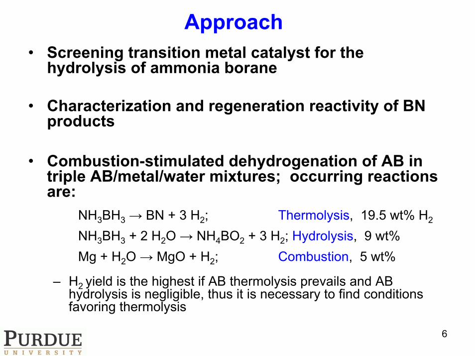
Approach• Screening transition metal catalyst for the
hydrolysis of ammonia borane
• Characterization and regeneration reactivity of BN products
• Combustion-stimulated dehydrogenation of AB in triple AB/metal/water mixtures; occurring reactions are:
NH3BH3 → BN + 3 H2; Thermolysis, 19.5 wt% H2
NH3BH3 + 2 H2O → NH4BO2 + 3 H2; Hydrolysis, 9 wt%Mg + H2O → MgO + H2; Combustion, 5 wt%
– H2 yield is the highest if AB thermolysis prevails and AB hydrolysis is negligible, thus it is necessary to find conditions favoring thermolysis

7
Accomplishments/Progress/Results
NH3BH3 + 4 H2O NH4B(OH)4 + 3H2Mineral acids
Instant
NH3BH3 + 4 H2O NH4B(OH)4 + 3H2
TM cat.
RT
1. Mineral acid catalyzed
2. Transition metal catalyzed
Hydrolysis of AB

8
Transition Metal Catalyzed Hydrolysis of AB
Entry Catalyst Catalyst (mol%)
React. Time, min
1 RuCl3 0.2 32 RuCl3 0.1 63 RuCl3 0.05 204 CoCl2 3 55 CoCl2 5 36 Pd/C 1 257 PdCl2 5 25
Accomplishments/Progress/Results
9
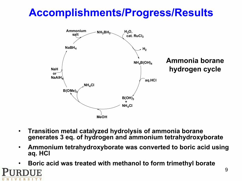
Ammonia boranehydrogen cycle
NH3BH3
H2
H2O,cat. RuCl3
NH4B(OH)4
B(OH)3+
NH4Cl
B(OMe)3
NaBH4
Ammoniumsalt
NaHor
NaAlH4
NH4Claq.HCl
MeOH
• Transition metal catalyzed hydrolysis of ammonia borane generates 3 eq. of hydrogen and ammonium tetrahydroxyborate
• Ammonium tetrahydroxyborate was converted to boric acid using aq. HCl
• Boric acid was treated with methanol to form trimethyl borate
Accomplishments/Progress/Results

10
Combustion wave propagation
Temperature in the combustion wave exceeds 500 °C, providing conditions for full dehydrogenation of AB. The possibility of some hydrolysis,
however, still exists.
NH3BH3:Al:H2O (2:3:3 mass ratio)Sample diameter 1 cm, height 2.5 cm
Images taken at 0.20, 0.33, 0.40 and 0.85 s after ignition
Reaction chamber and high-speed video camera
Composition H2 yield (wt%), experimental
H2 yield (wt%), theoretical
AB:Mg:H2O (4:4:3) 9.1 10.1
AB:Al:H2O (2:3:3) 7.7 8.7
Accomplishments/Progress/Results

11
Isotopic tests of AB under Ar/D2O flow in TGA(pressure 1 atm)
MS
sig
nal
H2 (thermolysis)
HD (hydrolysis)
Temperature (°C)
TGA/MS experiments with AB under Ar/D2O flow at atmospheric pressure indicate the prevalence of thermolysis, as the amount of released H2 well exceeds that of HD.
TGA instrument MS measurements of generated H2 and HD
Accomplishments/Progress/Results

12
Isotopic tests of AB with D2O in Parr reactor(initial Ar pressure ~14 atm)
Experiments in Parr reactor result in higher amounts of HD as compared to H2, indicating that higher pressure promotes hydrolysis.
Parr reactor MS measurements of generated H2 and HD
Accomplishments/Progress/Results

13
Future Work• To achieve the conversion of methyl borate to
sodium borohydride in high yield • To accomplish ammonia borane regeneration in
overall near quantitative yield and in cost effective manner– Go/no go: ammonia borane overall yield of ≥ 60%
• TGA/MS experiments– higher D2O vapor pressure
• Parr reactor– detailed elevated pressure data for the reaction with D2O– analyze product solutions (NMR)– measure concentrations of impurities in generated H2 (FTIR)
• Combustion stimulated hydrolysis– analyze both gaseous and solid byproducts (FTIR and XRD)– test the effect of D2O on gaseous products (MS)

14
Summary
• Studied different transition metal catalysts for hydrolysis and observed that RuCl3 gives the best results
• Isolated boric acid from the ammonium tetrahydroxyborate by aq. HCl treatment
• Boric acid was converted to trimethyl borate in the presence of methanol
• Self-sustained combustion was observed in mixtures of AB with water and Mg or nano-Al powder; the maximum hydrogen yield was 9 wt%
• Isotopic tests of AB using D2O show that thermal decomposition competes with hydrolysis; higher pressure promotes hydrolysis

15
Objectives (Thermal Management of Recyclable Chemical Hydride Systems)
• To demonstrate a recyclable chemical hydride hydrogen storage system– Construct and test an AB hydrogen generation
system up to 1-kWel
– Construct and test a 0.2 kg AB/day regeneration system
• To increase system-based volumetric and gravimetric hydrogen densities– Investigate thermo-chemical properties and
processes experimentally and/or numerically to guide system design and optimization

16
Approach
• Investigate reaction kinetics and other key thermo-chemical properties
• Utilize numerical simulations to guide system level (subscale) test apparatus design
• Study key issues in the application of AB hydrolysis onboard hydrogen storage systems, using pre-system-level test apparatus
• Construct or renovate system level apparatus• Conduct system level tests

17
Accomplishments/Progress/Results• Mobile AB or SBH hydrolysis
apparatus– Packed reactor: 3 wt% Ru on
carbon extrudate
reaction completed
X, cm
0 5 10 15 20 25 30
T, o C
0
20
40
60
80
23 ml/min, AB, w/o insulation20 ml/min, SBH (pH 14), w/ insulation
• First system-level AB hydrolysis test– 5 wt% fuel aqueous solution– Hydrogen flow rate: ~ 2.9 SLPM
Shorter reactor can be used for AB (w/o NaOH) hydrolysis

18
Accomplishments/Progress/Results• AB hydrolysis kinetics
0
0.5
1
1.5
2
2.5
3
0 10 20 30 40 50
t*, min
n H
2 / n
AB,0
16.6 25.6 35.6 55.6
Vsol : 9.9 ml n AB, 0 : 0.002535 molm* cat : 15.2 mg
Temperature, ° C
• AB hydrolysis reactor simulations
Reactors using cobalt will need much more volume and weight than those using ruthenium
y = -7683.7x + 28.5R2 = 0.9952
y = -7457.3x + 25.138R2 = 1
-1
0
1
2
3
4
5
6
0.003 0.0031 0.0032 0.0033 0.0034 0.0035
1/T, K-1
ln (k
)
3 w t% Ru on Carbon (present work)1 0 w t% Co on Alumina (Xu and Chandra, 2006)
Ea = 62 kJ/mol, A = exp(25.138) mol (kg-cat)-1 min-1
Ea = 63.882 kJ/molA = exp(28.5) mol (kg -cat)-1 min-1
0
0.2
0.4
0.6
0.8
1
0 0.05 0.1 0.15 0.2 0.25 0.3 0.35
z, m
x 0
5
10
15
20
25
30
V H2,
SLP
M
3 wt% Ru on carbon: x
10 wt% Co on alumina: x
3 wt% Ru on carbon: H2 flowrate
10 wt% Co on alumina H2 flowrate
m metal , gRu: 0.6Co: 7
m f0 = 64.3 g/min
[AB] inlet = 3.6 kmol/m3 @10 w t%P in = 14.4 psi
2
,
,
3 [ ]exp1 [ ]
H
AB o cat a
AB o u
ndn m E K ABAdt n R T K AB
⎛ ⎞⎜ ⎟⎜ ⎟ ⎛ ⎞−⎝ ⎠ = ⎜ ⎟ +⎝ ⎠

19
Accomplishments/Progress/Results• Pre-system-level test apparatus
– To study AB hydrolysis up to saturation condition
– To validate AB hydrolysis kinetics at high concentrations
– To quantify possible ammonia generation
– To study byproduct solubility
• AB aqueous solution densities
y = -0.0037x + 0.993R2 = 0.9981
0.85
0.87
0.89
0.91
0.93
0.95
0.97
0.99
1.01
0 5 10 15 20 25 30AB wt%
ρ, g
/ml
Reference [Ali, 2002] atSaturationMeasured Density
Linear Fit
T = 25oC

20
Accomplishments/Progress/Results• 30-Day long term storage stability test
“Closed” Configuration
“Open” Configuration
• Samples of 10% and 25% AB aqueous solution are being studied• Expandable bottle allows outgassing without significant pressurization• Bottle also minimizes evaporation
Stopper
Test Tube
AB Solution
Expandable Bottle

21
Accomplishments/Progress/Results• New AB hydrolysis reactor design
– To keep multiple point temperature profile probe– To prevent leakage when operating at high pressures– To facilitate reactants/products sampling

22
Future Work• Construction & testing of AB hydrolysis
apparatus– Key issue: possible operation difficulties at high fuel
concentrations caused by dissoluble byproduct and/or appreciable ammonia generation
– Go: no such difficulty occurs or problem can be solved without significant cost increase
– No-go: problem can’t be solved or can be solved but with significant cost increase
• Design, construction and testing of AB regeneration apparatus– Key issue: yield of AB recycling at system level– Go: yield > 50%– No-go: yield < 50%

23
Summary• AB hydrolysis (w/o NaOH) is faster than SBH
hydrolysis (w/ NaOH, pH 14); therefore smaller/lighter system may be used for same hydrogen output
• AB hydrolysis systems using cobalt will need much more volume and weight than those using ruthenium
• Other key issues in the application of AB hydrolysis onboard hydrogen storage systems, such as ammonia generation, byproduct solubility and long term storage stability, are being investigated

24
Objectives(Bio-hydrogen Production from Organic Wastes)
• Acquiring data for the volume of hydrogen produced from food waste by fermentation
• Conduct statistical testing to determine parameters that influence hydrogen production rate and optimal configuration
• Optimize the energy balance for a modular device for supply of thermal and electric energy
• Provide data and design information consistent with the DOE objective to utilize anaerobic biological processes as a source of the Hydrogen

25
Approach• Investigate methods to produce hydrogen from
various organic waste streams through the use of a fermentation process. – The long term goal is to develop a portable unit that can
process food or other waste streams locally and produce hydrogen that will subsequently be used to generate electricity in remote locations initially.
– Current efforts are concentrating on isolating biological consortia, characterizing their hydrogen producing capabilities, and determining optimal operating parameters as well as evaluating the interrelation with potential local energy system designs.
• We have recently expanded the energy model to also consider the possibility of producing potable water as part of the process.
26
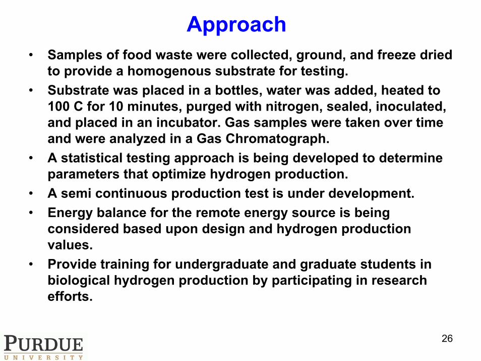
Approach• Samples of food waste were collected, ground, and freeze dried
to provide a homogenous substrate for testing. • Substrate was placed in a bottles, water was added, heated to
100 C for 10 minutes, purged with nitrogen, sealed, inoculated, and placed in an incubator. Gas samples were taken over time and were analyzed in a Gas Chromatograph.
• A statistical testing approach is being developed to determine parameters that optimize hydrogen production.
• A semi continuous production test is under development.• Energy balance for the remote energy source is being
considered based upon design and hydrogen production values.
• Provide training for undergraduate and graduate students in biological hydrogen production by participating in research efforts.

27System Overview
H bio reactorMethaneBio reactor
H feed stockprocessing
M feedstock
Solar collector Heat storage
Gas Conditioner InverterAC
DCFuel Cellor recip
Δ P ?
RawFeed
If Needed for process heat
Accomplishments/Progress/Results

28
• It has been possible to produce up to ~20 volume % hydrogen from initial non optimized tests.
• A statistical optimization testing scheme is currently being implemented.
• Initial work started on multiple testing device to conduct automated testing
• Energy balance calculations are being modified to accommodate testing results and input from industrial advisors.
• Semi continuous testing device is under construction.
• Progress is consistent with project milestones and objectives
Accomplishments/Progress/Results

29
Accomplishments/Progress/Results
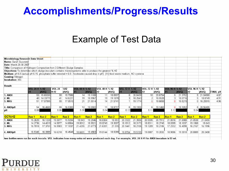
30
Example of Test Data
Accomplishments/Progress/Results

31
• Energy Balance Calculations
0 50 100 150 200 2500
0.2
0.4
0.6
0.8
1
1.2
1.4
1.6
1.8
2x 10⁴
hour of day
BTU
/hr
external heatsolar heatprocess heat
0 50 100 150 200 2500
1
2
3
4
5
6
7
8
9
hour
Tank
Len
gth
(m)
Tank Length required for the hour,assuming 2 m diameter
Accomplishments/Progress/Results

32
Future Work
• Determination of optimal parameters for hydrogen production from fermentation of food waste will continue.
• Multiple testing device is being developed. • Energy balance will continue to be
developed. • Feasibility of production of potable water as a
byproduct will be considered.• Concept for capture of carbon dioxide to
produce marketable chemical product will be considered.

33
Summary• Anaerobic production of hydrogen holds promise as a viable
source of energy.• Waste streams provide a low cost source of feed for the energy
production process. • This approach holds promise to provide an environmentally
friendly means to produce electricity in remote or third world applications.
• Identification of optimal operating parameters and consortia forhydrogen production is producing positive results.
• Statistical experimental design testing is underway. • Energy balance is being refined to accommodate information
from testing and commercialization concerns of industry advisors.
• New concepts to maximize value as a local energy source, consistent with DOE goals, are being considered such as production of potable water as a by product. CO2 capture is being considered using organometallic nanocatalyst.
• As the technology is developed there is the opportunity to scale up the size of the energy production.