Embed Size (px)
Citation preview

SPIRE
WorkpackageLE1
HeatPumpDemandSideManagement
Finalreport
Dr.NikhilkumarShah([email protected])
DrMingJunHuang([email protected])
Prof.NeilHewitt([email protected])
UlsterUniversity

2
ContentsListofFigures.........................................................................................................................................3
ListofTables...........................................................................................................................................4
1 Introduction...................................................................................................................................5
2 Testhousedetails...........................................................................................................................6
2.1 Heatinganddomestichotwatersystem................................................................................6
2.2 Datamonitoringsystem.........................................................................................................9
2.3 Testhouseenergyconsumption..........................................................................................11
3 Heatpumpasaretrofittechnology.............................................................................................15
3.1 Introduction..........................................................................................................................15
3.2 Heatpumpandthermalstorageselectioncriteria..............................................................17
3.2.1 Heatpumpselection....................................................................................................17
3.2.2 Thermalstoragetankselection....................................................................................18
3.3 Heatpumplaboratorytest...................................................................................................20
3.3.1 Testfacility...................................................................................................................20
3.3.2 Laboratorytestresults.................................................................................................22
4 Heatpumpintegratedthermalstoragefieldtrial........................................................................24
4.1 Heatpumpfieldtrialset-up.................................................................................................24
4.2 Testmethodology.................................................................................................................27
4.3 Resultsanddiscussion..........................................................................................................28
4.3.1 Directmodeperformance............................................................................................30
4.3.2 Storagemodeperformance.........................................................................................31
4.3.3 Combinedmodeperformance.....................................................................................34
4.3.4 Performanceandcostcomparison...............................................................................35
4.4 Conclusion............................................................................................................................37
References............................................................................................................................................38

3
ListofFiguresFigure1Radiatorheatoutputchangeswithrespecttoflowtemperatures..........................................5Figure2TerracedstreettesthousesatUniversityofUlster..................................................................7Figure3SpaceheatingandDHWsystemforterracedstreethouseatUniversityofUlster.................9Figure4Radiotelemetrydatalogger(EltekSquirrel1000series,RX250AL).......................................10Figure5Transmitterusedfordifferentmeasurement........................................................................10Figure6Dataacquisitionsoftware:Realtimeviewandstatusoftransmitters..................................11Figure 7 Test house heat demand including DHW demand (Simulated) at various ambienttemperature.........................................................................................................................................12Figure8Gasboilerperformance:Heatoutput,diningroom,flow/returntemperaturesampledata14Figure9TypicaldailyelectricitydemandpatternforTerracedstreethouses.....................................14Figure10Idealvapourcompressionheatpumpcycle.........................................................................15Figure11Aselectedheatpump:DaikinAlthermaHTheatpumpindoorandoutdoorunit...............18Figure12SelectedheatpumpCOPclaimedbymanufacturer............................................................18Figure13Schematics:Thermalstoragetank600l:customdesigned.................................................19Figure14Thermalstoragetankprocuredfortheproject....................................................................20Figure15Laboratorysetup forheatpumptesting:a.)Testchamber,b.)Outdoorunit, c.)Outdoorunit,d.)Heater,e.)Cooler,f.)Energy/current/voltagemeasurement,g.)Steamer,h,)Heater/coolercontroller, i.) Temperature sensors, j.)Water temperaturemanagement, k.) Three-way valve andactuator,l.)Humiditylevelbysteamer................................................................................................22Figure16HeatpumpCOPwithrespecttoairtemperatureatdifferentflowtemperatures..............23Figure17Powerconsumptionwithrespecttoairtemperatureatdifferentflowtemperatures.......23Figure18Timerequiredreachingdesiredflowtemperaturefromcoldstartat20°C......................24Figure19Powerconsumptionfluctuationsduringwarm-uptimeat80°Cflowtemperature..........24Figure20Platformwithshedsforheatpump/tankinstallation..........................................................25Figure21Heatpumpindoor/outdoorunit,shedheateranddataacquisitionsystem.......................25Figure22Thermalstoragetankintegratedwithheatpump...............................................................26Figure23Modificationtoexistingheatingsystemintheboilerroom................................................26Figure24Schematicsoftestsetup......................................................................................................28Figure25Househeatdemandovertestperiods.................................................................................29Figure26COPvariationsovertestperiods..........................................................................................29Figure27Heatpumpflow/returntemperatureandroomtemperature.............................................30Figure28Heatoutputbyheatpumpalowestefficiencyoperationday.............................................31Figure29Heatpumppowerconsumptionatlowestefficiencyoperationday...................................31Figure30Storagemode:Heatpumpoutputwithrespecttotanktemperatureduringcharging.......32Figure31Storagemode:Heatpumpflow/returntemperatureandpowerconsumption..................32Figure32Storagemode:Heatoutputfromstoragetankandroomtemperature..............................33Figure33Storagemode:Heatpumprunninghourswithde-statpumpoffandde-statpumpon.....33Figure34Heatoutputcomparisonduringfirst30minofhouseheatdemand...................................34Figure35Combinedmode:heatoutputtohouseinbystoragetankandheatpump........................34Figure36Combinedmode:Heatpumppowerconsumptionduringcharginganddirectmode........35Figure37Combinedmode:Tanktemperatureduringcharginganddischarging................................35Figure38HeatpumpannualrunningcostbasedonCOPandelectricitytariffs..................................36Figure39Annualheatingcostwithgas/oilboilerwithrespecttotheirefficiency..............................37

4
ListofTablesTable1Detailsaboutheatingsystem....................................................................................................7Table2Detailsofradiatorsinstalledinterracedhouse.........................................................................8Table3Domestichotwatersystem.......................................................................................................8Table4Domestichotwaterstoragetank,rechargetimeandheatoutputrequirement....................13Table5Annualgasconsumptionforterracedstreethouses...............................................................14Table6Typesofheatsourceandtheirtemperature(HPP,2013).......................................................16Table7Typesofheatdistributionsystemanddeliverytemperature(HPP,2013).............................16Table8HeatpumprunningcostwithCOP..........................................................................................36

5
1 IntroductionHeatpumpisanefficienttechnologyforheating/coolingwhichusesfreeenergyfromair,waterorground.However,inthedomesticsectorofUK,gasandoilboilersaremostcommontechnologyforproviding space heating and domestic hot water (DHW) through central heating system thatcontributesalmost78% indomesticenergyconsumptionand40%domesticheat relatedemission(DECC,2012a)(DUKES,2012a).Foraretrofittechnology(e.g.heatpump), itneedstomeetcertaincriteria to replace existing heating system as existing wet radiator system requires higher flowtemperaturetomeettheirheatdemand(Hewitt,etal.,2011).Inaddition,heat/electricitydemandpatternduringwinter/summerandpoorlyinsulatedhousingstockintheUKinfluencessizingofheatpump.Anotherissueiswithelectricitygridwhichhaslimitationonhowmanyheatpumpscanrunatsametime,Inaddition,italsocurtailselectricitygeneratedfromrenewablesourcessuchaswind.
Heatpumpsareclassifiedbasedonflowtemperatureitcanprovidefromcondenser.AsperBSEN14511-2013(BSI,2013),heatpumpsaredividedaslowtemperature(35°C),mediumtemperature(45°C),hightemperature(55°C)andveryhightemperature(>65°C).Inorder,toworkefficiently,heatpumpneedspossible lowflowtemperaturewhereasconventionalwetradiatorsystemworkswith high flow temperature. Radiators for central heating systemare designed as per BS: EN 442(BSI, 2014)which suggests 75°C flow and 65°C return temperature with mean temperaturedifference of 50°C. In radiator, flow temperatures below or above design temperature changesheatemissioncapacity.Forexample,radiatorsweredesignedandinstalledtoworkwithcondensinggasboilersystemtomeettesthousesheatingdemandatUniversityofUlster. If lower/higherflowtemperatureissuppliedinthoseradiatorsthenitwouldchangeheatoutputfromradiators.
Figure1Radiatorheatoutputchangeswithrespecttoflowtemperatures
Figure 1 shows such radiators heat output increment/decrement with flow temperature wheretemperaturedifferenceof5Kand10Khasbeenconsideredbetweenreturnsandflow.Ifastandardheatpumpwhichprovides55°C flow temperature is installedwith suchexisting radiator then itwouldreduceheatoutputby41-47%basedontemperaturedifferencebetweenflowandreturnandhence,thermalcomfortwouldbereduced.Inordertosolvethisproblem,standardradiatorshould

6
be replaced by oversized/advanced radiators or very high temperature heat pump should beinstalled.EvenEnergySavingstrust’sheatpumpsfieldtrialdidnotcoveranyveryhightemperatureheatpumpinsteadtheyusedstandardheatpumpwithoversized/advancedradiatorsorunderfloorheating(Dunbabin,etal.,2013).
Inorder toaddressall issuesmentionedabove,veryhigh temperatureheatpump installationhasbeencarriedoutwiththermalstorage.Mainaimofpresentworkwastohighlightperformancedata,potential, problems related to heat pump/thermal storage and demand side strategies to tackleelectricitygridproblemsconsidering thermalcomfortofadwelling incentre. In thenext sections,details about testhouse,monitoring system,heatpump laboratory test and field trial result havebeendiscussedinmoredetailaspartofUlsterUniversity’sdeliverablesforworkpackageLE1.
2 TesthousedetailsIn order to understand retrofit challenges of insulation, material, glazing and renewablestechnologies installation, twomid-terraced type test houses were built in ‘Terrace Street’ at theJordanstowncampusoftheUlsterUniversity.Thehouseswerebuiltto1900designspecificationsinorder to allow detailed analysis of typical ‘hard to heat’ homes. Such kind of dwelling representsmostcommontypesofhousingstock(27.6%)acrossNorthernIreland(NIHE,2011).Figure2showsthemid-terracedhousesbuiltatUniversityofUlster.Thehousesare96m2andtheyareofsolidwallconstructionandhavebasicloftinsulation(150mm)andPVCdouble-glazedwindowsanddoors.Theareas highlighted by the red lines are separate from the dwellings and contain monitoringequipment.Theguardchambershavetheirownheatsourceandaremaintainedat21°Cinordertoreplicatemid-terraceconditions for thedwellings.These spaceshave theirownseparatedoors toallowresearchersconstantaccess.Thehousesareoccupiedbytwofamilies;House63byaworkingcouplewholeavethehousebefore9.00amanddonotreturnuntilafter5.00pm;andHouse64bya3-personfamilywithastudent-agedson,whoisoftenathomeduringtheday.
2.1 HeatinganddomestichotwatersystemAllwork in thehousewas carriedout tomake it adaptable formonitoring and future retrofit (orrenewables technology) purposes. Each house is fitted with a gas fired boiler. The LTHWpressurizationunitis independentoftheboiler.Allpipesenteringandleavingtheboilerwasfittedwith accessible ¼ turn handle isolating ball valve for quick removal (or bypass) of the boiler. Acirculatingpumpwasprovidedwithisolatingvalvesoneithersideofthepumpandabypasstoallowboiler (orheatpump) tobe fittedwith integral circulatingpumps.Alldistributionpipework to thehouses was done by copper with solder joints. The heating system within the house has to beadoptableandhence,fullyaccessible isolationvalvewasprovidedontheflow&returntoeachofthefollowing:
• Eachradiator• Eachdroptomultipleradiators• Boiler• Groundfloordistribution• 1stfloordistribution• Hotpresscylinder

7
More details about installed gas boiler, pressurization unit, pump etc. have been summarized inTable1
Figure2TerracedstreettesthousesatUniversityofUlster
Inordertodistributehotwaterfromgasboiler,conventionalradiatorswereinstalledinthehouse.EachradiatorwasfittedwithaTRV(Thermostaticradiatorvalve)ontheflowandalockshieldvalveonthereturn.Theradiatorsinthebathroomswerefittedwithlockshieldvalvesonthebothflowandreturntoactasaheatleak.AllradiatorswerehorizontalpaneltypemanufacturedbyZehnderNova.ThelistofradiatorsinstalledwiththeirsizeandcapacityhasbeengiveninTable2
Table1Detailsaboutheatingsystem
BoilerRatedoutput 21kWType Gasfiredcondensingboilerto1995Regs(notcurrentRegs),suitable
forexposedunheatedstoreManufacturer BaxiReferencenumber SoloHEA24kWFuelOil NaturalGasElectricalsupply 1phaseMaximumoperatingtemperature
82°C
PressurizationunitMinimumsystemtemperature
71°C
GuardChamber
House63House64

8
Averagesystemtemperature
76°C
Maximumoperatingpressure
3.0bar
Systemstaticheadof 4.0mPackageconsistof • Singlephasecentrifugalpump
• Metal clad isolating switch c/w neon indicator • Two pressure gauges • Pressure reducing valve • Pressure switches • Hydraulic accumulator • Non-return valve and ancillary pipe fittings • Expansion vessel
HeatingcirculatingpumpFlowrate 0.5l/sPumpratedpressure 120kPaType Inline(Grundfos)Electricitysupply 1phase
Table2Detailsofradiatorsinstalledinterracedhouse
Location Heatingduty(kW)
Dimensions(LxH)(mmxmm)
Notes
Groundfloorcorridor 0.8 1000x425 DoublepanelsinglefinLivingroom 0.9
1.01000x354750x425
DoublepaneldoublefinDoublepaneldoublefin
Diningroom 0.8 1000x283 DoublepaneldoublefinKitchen 1.0 1000x425 DoublepaneldoublefinBedroom1 0.5
0.51000x2121000x212
DoublepaneldoublefinDoublepaneldoublefin
Bedroom2 0.7 1000x283 DoublepaneldoublefinBedroom3(boxroom) 0.8 500x567 DoublepaneldoublefinBathroom 0.5 500x425 Doublepaneldoublefin
HeatleakradiatorUpstairslanding 1.0 750x496 Doublepaneldoublefin
ThedomestichotwaterisprovidedtoeachhousebymainsfedventedcalorifierwithaLTHWcoilandasecondcoilforfutureresearchandelectricimmersionheater.Thehotwatershallbesettooperateat50-65°C.Table3showsthearrangementforDHWinthetesthouse.
Table3Domestichotwatersystem
Parameter ValueMaximumhotwatersupplytemperatureattaps 45°C
Calorifierdimensions 500mmx1200mmStorageVolume 0.203m3
Energystoragecapacity(45°Cminuseful) 4.71kWh

9
InordertocontrolheatingandDHWsupply,domesticcontrolpackbyDanfossconsistingoffollowingwasinstalled:
• Submersiblehotwatercylinderthermostat• RMTadjustableroomwallthermostat• 3portcontrolvalvefordomestichotwatercylinderhatingcircuit• ATCanadjustablehotwatercylindertemperaturethermostat• 2No.22mm2portvalvetooperateheatingsysteminhotwatermodeonly• SET3M7daywallmountedheatingandhotwaterprogrammertimercontroller
Theset-upofheatingsystemandhotwatercylinderissubjecttoenduseraspertimeclockoperation;temperaturesetpointofhotwatercylinderandroomthermostatetc.anditisnotinfluencedoreducatedbytheUniversityresearchteam.TypicalarrangementofspaceheatingandDHWsystemhasbeenshownFigure3whichrepresentstheuseofgasboilerforspaceheatingviahightemperatureradiatorsandDHWbymeansofhotwatercylinder.
Figure3SpaceheatingandDHWsystemforterracedstreethouseatUniversityofUlster
2.2 DatamonitoringsystemInordertomonitoruserbehaviourandenergydemand,parameterssuchastemperature,humidity,flow rate and gas/electricity consumption etc. were monitored constantly. Two desktops wereplacedinguardchambernexttohouse63.ThosePCswereconnectedtonetworkandusedtostoredata from data acquisition system. In order to avoid inconvenience to tenants wireless radiotelemetry type data logger and transmitters were used to monitor different variables. For thispurpose, Eltek Squirrel 1000 series type RX250 AL receiver logger was used. The RX250 AL isresponsible for receiving and storing the data and it is not necessary to have a PC permanentlyconnected.Thebuilt-inbatterymeansdataloggingisnotinterruptedevenifthereisatemporaryACmains failure. Figure 4 shows RX250AL type data logger used for monitoring purpose. Two dataloggerofsuchtypewereinstalledandconnectedwithdedicatedPC.

10
Inordertomonitoreachroomtemperatureandhumidity,adedicatedtransmitter(EltekGD10typewithdisplay)withbuiltindigitaltemperature/humiditysensorwasinstalledineachroom.Inordertomeasureflow/returntemperatureoneachfloorlineandDHWcylinderlinealongwithinlet/outletofcylinder,transmitterswith inputforthermocoupletemperaturesensor(withdisplayEltekGD24type)wereinstalled.Transmitterswithinputsforpulseandstate(EltekGC62type)wereinstalledinordertomeasureflowrateineachlineandpulseoutputfromenergymeter.Total15transmitterswere installed in each house out of which seven were temperature/humidity type, two werethermocouple type and six were pulse type transmitters. Figure 5 shows different type oftransmitterusedinpairwithreceivertomonitorvariousparameters.
Figure4Radiotelemetrydatalogger(EltekSquirrel1000series,RX250AL)
Figure5Transmitterusedfordifferentmeasurement
Data logger integratedreceiverwasconnectedwithPCviaRS232serialportandEltekprogrammeDarcaPluswasused to arrange channel setup, logging interval timeetc. Thisprogrammeenablesrealtimedatainaformofchartandalsoprovidesstatusandbatterylifeoftransmitters.Forthetesthouses,datawere loggedatoneminute intervalandstored indedicated folderofSkyDrivewhichcan be remote accessed from anywhere for data analyses purposes. Figure 6 shows real timemonitoreddataofthehouseandstatusoftransmitterandloggingtimeetc.

11
Figure6Dataacquisitionsoftware:Realtimeviewandstatusoftransmitters
2.3 TesthouseenergyconsumptionBasedonthedataavailablefromthecontractorandmaterialusedforconstruction,heatlossfromthe house was calculated. Heat loss was simulated at various ambient temperatures in order toassess the requirement of future heating system. The heating demand calculation included spaceheatinganddomestichotwaterdemandforthreememberfamily.Figure7showheatlossvariation

12
or heating demand for the test house at various ambient temperatures. The room internaltemperatureset-pointwasdifferentfordifferentroomandassumedasperstandardpractice.
Figure7TesthouseheatdemandincludingDHWdemand(Simulated)atvariousambienttemperature
Inaddition,annualheatingdemandwascalculatedbasedonheatingdegreedaydata (HDD).HDDdatawereobtainedfromCloughfen,Newtownabbeyweatherstation.HDDdatawasgeneratedfor2014 considering temperature of 18˚C. In 2014, therewere 3212 heating degree days. Based onHDDandspecificheatloss,annualspaceheatingdemandforwas23974kWhandDHWdemandwas3846kWhgivingtotalheatdemandof27820kWh(or290kWh/m2).Fromestimatedcalculationitwas very clear that the house has significant heat loss and this could beworst case scenario forretrofitapplication.Inordertobesurethatcalculatedheatingdemandiswithinacceptablerange,itwas cross-checkedwithmeasured energy consumption for themonth of December and January.Based on their comparison, it was found that heating demand calculationwas correctwith 1-4%errorcomparedtomeasuredvalueandwhichwasmainlyduetounpredictableuserbehaviour.
Inadditiontototalheatlossfromthehouse,domestichotwaterdemandwithnumberofpersonswas also estimated in order to understand storage size and recharge time. For calculation, 55l/person, recharge time of 2 hour,water inlet temperature at 10°C and storage temperature of60°Cwereassumed.Itisstandardpracticetouseminimumof114litresstoragetankfordwellingswith1,2,3ormorebedroomand75 l/person for2bedroomand55 l/person for3bedroomsormore.Basedonthatfor2people,114litresstoragewasconsideredandafterthat55l/personwasconsideredforstoragetankcalculation.
Table4showsheatoutput,storagesize,rechargetimeandheatoutputrequired(asperBS1566)fordomestic hot water. It is not practical to oversize boiler based on rapid recovery time however;control systemcanprovidehotwaterbasedonpriorityover spaceheatingand canprovide rapidrecovery.

13
Table4Domestichotwaterstoragetank,rechargetimeandheatoutputrequirement
Noofperson DHW(kW)Rechargetimewith(3kW)immersionheater
Storagetanksizeused(litres)
Heatoutput(kW)for25minrapidrechargeasperBS1566
1 3.33 2h15min 114 162 3.33 2h15min 114 163 4.81 3h15min 165 23.14 6.42 4h15min 220 30.85 8.02 5h20min 275 38.66 9.63 6h25min 330 46.3
Basedonthose informationavailableandfurtherdataobtainedfromhousemonitoring,gasboilerperformance in terms of flow temperature and room temperature set-point were analysed. Theinformation provided strong basis for selection and size of retrofit technology. Figure 8 showssampledataofgasboilerflow/returntemperature,heatoutputandroomtemperatureforaspecificday.Gasboiler isable to rampupheatoutputupto22kWwhichwasmainlyhelpful inacaseofDHWdemand.Theuserbehaviourshowstypicalheatdemandpatternduringadaywithmorning,afternoonandeveningpeak.Similarly,electricitydemandalsovariesdailywhichismainlyinfluencedbytheoccupancyinthehouse.Figure9showstypicalelectricitydemandpatternfor15dayswherehouse64hashigherelectricitydemandcomparedtohouse63duetohigheroccupancy.Electricitydemandvariesbetween7to18kWhand2to6kWhforhouse64andhouse63respectively.

14
Figure8Gasboilerperformance:Heatoutput,diningroom,flow/returntemperaturesampledata
Figure9TypicaldailyelectricitydemandpatternforTerracedstreethouses
Inaddition toelectricity trend,overallannualheatingenergysupplied to the terracedhouseswastabulatedbasedontheircombinedusagefromgasbill.Table5showsgasenergyconsumptionandcostassociatedwithit.Basedontotalenergyconsumption,itwasfoundthataverage22738kWhofenergysuppliedbynaturalgasperhousewhichcostabout£1199/yearforahouse.Thistranslatesto237kWhperm2ofenergyconsumptionor£12.5perm2forahouseonanannualbasis.Basedonthis information, possible installation, running cost and efficiency requirement for retrofit orrenewabletechnologycanbeestimated.
Table5Annualgasconsumptionforterracedstreethouses
House63 House64 CombinedTotal GaskWh Cost£ GaskWh Cost£ GaskWh Cost£Dec-13 2970.68 164.44 3487.32 193.04 6458 357.48Jan-14 3056.24 168.82 3587.76 198.18 6644 367Feb-14 2503.32 139.85 2938.68 164.18 5442 304.03Mar-14 2373.14 133.02 2785.86 156.15 5159 289.17Apr-14 1487.64 70.51 1746.36 82.77 3234 153.28May-14 748.42 36.35 878.58 42.67 1627 79.02Jun-14 561.2 27.92 658.8 32.77 1220 60.69Jul-14 862.96 41.65 1013.04 48.90 1876 90.55Aug-14 922.3 44.52 1082.7 52.26 2005 96.78Sep-14 1754.9 83.35 2060.1 97.85 3815 181.2Oct-14 2101.74 117.55 2467.26 138.00 4569 255.55Nov-14 1576.42 74.92 1850.58 87.95 3427 162.87AnnualTotal 20919kWh £1103 24557kWh £1295 45476kWh £2398
Average 22738kWh/year £1199/year
AverageAnnual 237
kWh/m2 £12.5/m2
15
3 Heatpumpasaretrofittechnology
3.1 IntroductionHeat pump is an efficient technology for heating, cooling or DHW based on vapour compressioncycle.Heatpumpsaredevicesthatfollowthesecondlawofthermodynamics.Asperthesecondlawof thermodynamics, to move heat from a low temperature state to a high temperature state, itrequiressomeworkorenergy input.Aworking fluid,knownasrefrigerant isused inaheatpumpcycleforheattransferprocessfromlowtemperaturestatetohightemperaturestatebymeansofworkadditiononthesystem.Theworkinputgenerallyprovidedbymechanicalmeansbutitcanalsobeprovidedbymeansofelectrical,heat,magnetism,laserorothermeans.TheprincipleoftheheatpumpcanbeexplainedbyheatengineorCarnotengine theory.Heatpumpsystemsworkexactlythesamewaybutreverseinthecaseofwork.Heatenginesproduceworkwhereastheheatpumpconsumesworkwithtransferofheat.Heatpumpconsumesworkorenergyinordertoconvertlowtemperatureheattohightemperaturetosupplyforvariousapplications.
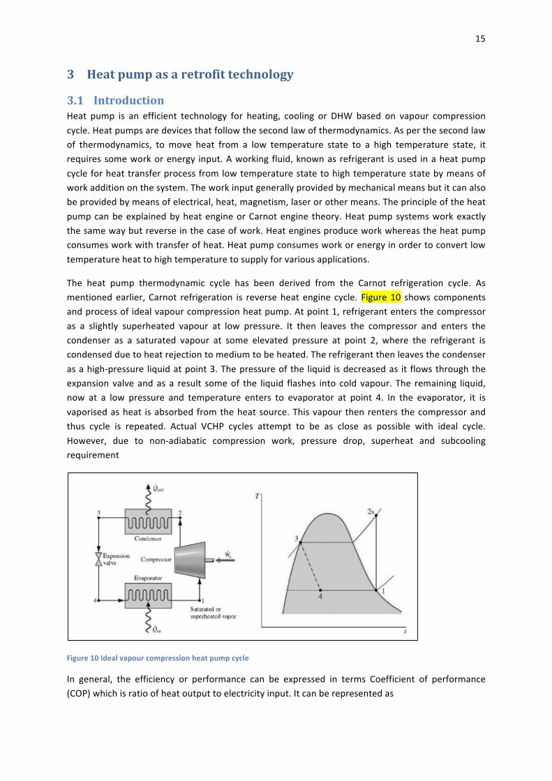
The heat pump thermodynamic cycle has been derived from the Carnot refrigeration cycle. Asmentionedearlier, Carnot refrigeration is reverseheat engine cycle. Figure10 shows componentsandprocessofidealvapourcompressionheatpump.Atpoint1,refrigerantentersthecompressoras a slightly superheated vapour at low pressure. It then leaves the compressor and enters thecondenser as a saturated vapour at some elevated pressure at point 2, where the refrigerant iscondensedduetoheatrejectiontomediumtobeheated.Therefrigerantthenleavesthecondenserasahigh-pressure liquidatpoint3.Thepressureofthe liquid isdecreasedas it flowsthroughtheexpansion valve andas a result someof the liquid flashes into cold vapour. The remaining liquid,now at a low pressure and temperature enters to evaporator at point 4. In the evaporator, it isvaporisedasheat isabsorbedfromtheheatsource.Thisvapourthenrenters thecompressorandthus cycle is repeated. Actual VCHP cycles attempt to be as close as possible with ideal cycle.However, due to non-adiabatic compression work, pressure drop, superheat and subcoolingrequirement
Figure10Idealvapourcompressionheatpumpcycle
In general, the efficiency or performance can be expressed in terms Coefficient of performance(COP)whichisratioofheatoutputtoelectricityinput.Itcanberepresentedas
16
𝐶𝑂𝑃$% = 𝐻𝑒𝑎𝑡𝑑𝑒𝑙𝑖𝑣𝑒𝑟𝑒𝑑𝑊𝑜𝑟𝑘𝑖𝑛𝑝𝑢𝑡
= 𝑄$𝑊89
= 𝑄$
𝑄$ −𝑄;=
1
1 − 𝑄;𝑄$
RatioofactualCOPandanidealCOPiscalledCarnotefficiency.Carnotefficiencyrangesfrom0.3to0.5 forsmallsystemelectricheatpumpwhereas0.5to0.7 fora largesystem.AnotherparameterthatisusedformeasurementofannualperformanceofheatpumpsystemisSeasonalPerformanceFactor (SPF). SPF considers annual heat output by heat pump system to total annual energyconsumedbyheatpumpincludingdefrost,fans,pumpsandotherauxiliarydevicesetc.SPFcanberepresentedas
𝑆𝑃𝐹 = ?@@ABCDEBFGAFHAF(JKD)?@@ABCE@EMNOPG@QARES(JKD)
There are various heat sources or sinks can be used for heat pump applications. However,mostcommonheatsource/sinkusedisair,water,ground,rock,wasteheatetc.Availabilityofeachsourceisdependentonseason,location,temperature,localregulationsandcostassociatedwithit.Table6showsmostcommontypeofheatsourcesandtheir temperatureused forheatpumpapplication.Similarly,themostcommontypeofheatsinkisairorwaterfordomesticapplication.Table7showsdifferenttypesofheatdistributionsystemandtheirtemperaturerange.Ifheatpumpusesairasaheatsourceandwaterasasinkthen it isdefinedasAir-to-waterheatpump. Inthesamemannerheatpumpcanbeclassifiedbasedonsourceandsinkused.
Table6Typesofheatsourceandtheirtemperature(HPP,2013)
Heatsource Temperaturerange(°C)Ambientair -10to15Exhaustair 15to25Groundwater 4to10Lakewater 0to10Riverwater 0to10Seawater 3to8Rock 0to5Ground 0to10Wastewaterandeffluent >10
Table7Typesofheatdistributionsystemanddeliverytemperature(HPP,2013)
Application Supplytemperature range(°C)
Airdistribution Airheating 30-50 Floorheating;lowtemperature(modern) 30-45Hydronicsystems Radiators 45-55 Hightemperature(conventional)radiators 60-90 Districtheating-hotwater 70-100 Underfloorheating 30-35Districtheating Districtheating-hotwater/stream 100-180 Cooledair 10-15Spacecooling Chilledwater 5-15

17
Districtcooling 5-8
As per Great Britain‘s housing energy fact file, there are about 26million dwellings in the GreatBritain(Palmer&Cooper,2011).In2008,almosteveryhomehadinstalledcentralheatingsystem.Only4%(1.04millions)oftheUKhousingstockleftwithoutcentralheating,with96%havingsomeform of central heating system to meet their space heating and hot water demand. The houseswithout central heating,met their heating demandmainly by gas (50.5%) and electricity (41.4%)whereascentrallyheatedhomesmettheirheatdemandmainlybygas(85.3%) . For a retrofittechnology(e.g.heatpump), itneedstomeetcertaincriteriatoreplaceexistingheatingsystemasexistingwetradiatorsystemrequireshigherflowtemperaturetomeettheirheatdemand(Hewitt,et al., 2011). On theother side,heatpumpworkefficiently at lower temperature rangeof45 to55°Cwhichisidealforunderfloorheatingorspaceheatingwithmodernradiatorsbutforretrofitapplication without replacement of radiators it needs to supply high temperature where itperformance drops. Hence, modern heat pump selection should be considered for such retrofitapplication.Otherefficienttechnologysuchaswind,solarthermal,solarPVandmicroCHPhasnotbeenconsideredheredue to their intermittent supply, cost, space requirementandnoiseetc. fordomesticsector.
3.2 Heatpumpandthermalstorageselectioncriteria
3.2.1 HeatpumpselectionBased on test house data monitoring and heat loss simulation, it was estimated that the houserequires about 11 kW of heat at 0°C ambient temperature. The house with higher occupancy(house 64) was selected for heat pump installation due to higher energy demand which wouldprovide good understating of heat pumpperformance. In addition, heat pump installation shouldsolve real purpose of retrofit applicationwhich does not require any replacement of radiators orcontroller.Thishelpsincostsavingandeducatingtenantsfromanewtechnology.Followingcriteriawerelaiddowninordertoselectheatpumpasaretrofitapplication:
• Itshouldbeabletomeetheatingdemandof11kWat0°Cambienttemperature• Flowtemperatureinarangeof73to80°Cforconventionalradiators• Minimumchangeoradditiontoexistingsystemorcontrol• Simpletousefortenantswithouteducatingthemaboutnewsystem• Easytointegratewiththermalstorage• ItshouldmeetbothspaceheatinganDHWdemand
Based on above criteria, Daikin Altherma HT heat pump was selected for the application. It iscascadetypeheatpumpwheretwoheatpumpsoperatetogether.TheoutdoorofheatpumpwasDaikinERSQ011AAV1.IthasR410Arefrigerantwhichcanworkevenatambientairtemperatureupto -20°C and it provides heat to indoor unit. The indoor unitwasDaikin EKHBRD01AAV1. It hasrefrigerantR134awhichcandeliverhotwatertemperatureupto80°Canditgainsheatfromtheoutdoorunit.Aselectedheatpumphasvariablespeedpumpandcompressorwhichcanramp-uporrampdownspeedbasedonhouseheatingload.Hence,suchsystemhelpstoreduceon-offcyclinglosseswhichareverycommoninfixedspeedheatpump.Figure11showsindoorandoutdoorunitofselectedheatpump.Indomesticapplication,outdoorunitisinstalledoutsidehouseingardenor

18
backyardwherefreeflowofambientairisavailableandindoorunitcanbeinstalledinsidethehouseinboilerroom,basementorgarageasperavailablespace.
Figure11Aselectedheatpump:DaikinAlthermaHTheatpumpindoorandoutdoorunit
Figure12SelectedheatpumpCOPclaimedbymanufacturer
Inordertounderstandefficiencyofheatpump,agraphwaspreparedbasedonmanufacturerdata.Figure12showsCOPvariationwithrespectairtemperatureandwaterflowtemperature.Basedonmanufacture claim, heat pump COP should be in a range of 2 for air temperature around 0°C.However, claimed COP does not include power consumer by pump or stand by power or defrostenergywhereas in field trialall thoseparameterswouldbe includedand thusCOP from field trialdatawouldbelowerbutitwouldprovidetrueindicationofheatpumpefficiencyandperformance.
3.2.2 ThermalstoragetankselectionThere are twomain reason touse/select thermal storage tank: 1.) Touseoff –peak electricity byheat pump and store thermal energy and when there is heat demand, deliver energy from the

19
thermalstore,2.)Tohelpheatpumpoperationindefrostmodeand/orhelpinheatpumpwarmuptime,henceprovingmorethermalcomfort(orsimilartogasboiler)totenants.
Gasboilerperformancedataweretakenintoconsideredforthermalstoragedesignandselectionsothatthermalstoragecanprovidesameamountofheatenergywhenthereisafirstcallofheatinthemorning.Testhouseheat losssimulationshowedthatspaceheatingdemandforhousewas intherangeof8kWat-4°Cambienttemperature.Inaddition,gasboilerperformancedatashowedthatduringfirstcycle(about1hour)inthemorningitprovidesabout18kWhandabout9kWhenergyuntilitflowtemperaturereachesintherange76°Cfromcoldstartat20°C.Hence,storagetankwasdesigned toprovide8 kWh.For the sizing, simpleequationQ=mcDTwasusedwhereDTwasassumed10KandC=4.18kJ/kgK.Itwasfoundthatitrequiresabout689litresofstoragevolume.
Figure13Schematics:Thermalstoragetank600l:customdesigned
However,due to constructionandmaterial limitation,maximumof600 litres copper storage tankwas custom designed and procured form commercially available supplier. Figure 13 showsschematicsofthermalstoragetankandportsavailable.Ithad3.5m2heatpumpcoilanddischargecoil to supplyenergy to thehouse. It had75mm thick insulation, 2x21/4"heaterbosses, 7x1/2"bosses,1x1"bossesfortemperaturesensorsandremovablelidontopforfuturework.Thestoragetankwas2mhighand0.6mindiameter.Figure14showsprocuredtankpictureandinsideviewofthetankpresentingcoilsandports.
Fromheat pumpoutput data and storage design, itwas calculated that in order to bring storagetemperaturefrom45°Cto75°Cwithheatingcapacityof11kW,heatpumpwouldtakeabout2h.Hence, itwouldbe idealtorunheatpumpduringnighttimetochargethetankwithuseofcheapelectricityanddeliverheat inthemorningwhenthere is firstdemandforheatandhighelectricityprice. Thiswould help to shift electricity demandwithout compromising thermal comfort for thetenants.

20
Figure14Thermalstoragetankprocuredfortheproject
3.3 Heatpumplaboratorytest
3.3.1 TestfacilityAselectedheatpumpwastestedin laboratoryconditionsinordertounderstandtheperformancecharacteristicsbefore itcanbe installed inthehouses.Forthispurpose,CalorimeterchamberwasusedwhereheatpumptestcanbecarriedoutasperBSEN14511-3.Calorimeterhas15kWheaterand1.5kWcoolerandthreesteamers inordertomaintainchambertemperatureandhumidityatdesired level with the help of PID controller. Figure 15 shows laboratory set-up for heat pumptesting. Heat pump outdoor unit was placed inside the test chamber (Figure 15a) where it hadseveralpressureandtemperaturesensorswereattached(Figure15b).Heatpumpindoorunitwasplaced outside test chamber (Figure 15c) where it was connected to water tank and watertemperaturemanagementsystem(Figure13j).Testchambertemperaturewasmaintainedconstantbyheater(Figure15d)andcooler(Figure15e)withthehelpofcontrolpanel(Figure15h)whichhasPIDcontrolforprecisetemperaturemanagement.Thecoolercanachievestart-uptemperaturesofbetween -15and15°Candalsooffset thedefrosteffectof the testheatpump.Theheater isalsorequiredtoachievestart-uptemperaturesbutmustalsooffsetthecoolingcapacityofthetestheatpump to maintain the set-temperature. Test chamber and water temperature was measured by

21
temperaturesensor(Figure15i)andsteamer(Figure15g)wasusedtomaintainhumiditylevelinsidethechamber(Figure15l).

22
Figure15Laboratorysetupforheatpumptesting:a.)Testchamber,b.)Outdoorunit,c.)Outdoorunit,d.)Heater,e.)Cooler, f.)Energy/current/voltagemeasurement,g.)Steamer,h,)Heater/coolercontroller, i.)Temperaturesensors, j.)Watertemperaturemanagement,k.)Three-wayvalveandactuator,l.)Humiditylevelbysteamer
In order tomaintain constantwater temperature at heat pump inlet and outlet, dedicatedwatercircuitwasprepared.Thiswatercircuitconsistedofheatexchangerplate,storagetank, threewayvalve,actuatorandPIDcontroller.Heatpumpperformancewasmonitoredwiththehelpofalltheseinstrumentation and controller device and data were logged by data acquisition system in adedicatedPC.
3.3.2 LaboratorytestresultsHeatpumpperformancewastestedtoprovidedifferentflowtemperatureof45°Cto75°Catairtemperaturebetween-7°Cto12°C.However,forretrofitapplication,heatpumpperformanceatflowtemperatureof75Cwasmoreimportant.Duetofrequentdefrostcycleoperationathighflowtemperature,steadystateconditionswasobtainedbetween2to12Cair temperatures.Figure16showsvariationofCOPwithrespectairtemperatureandflowtemperature.ItshowedobviousresultthatCOPdropsatflowtemperatureincreasesorambienttemperaturedecreasesduetoincreasedpressure ratio at compressor. Figure 17 shows variation in power consumption which variedbetween3kWto8kWwithair temperatureand flow temperature.This informationwasused indeciding power supply to the house and further modifications required to the existing sockets,wiringetc.Duringthetest,heatoutputremainedinarangeof11to16kWasduetovariablespeednature of compressor and water pump which could be different domestic application based onpressuredropinpipes.

23
Figure16HeatpumpCOPwithrespecttoairtemperatureatdifferentflowtemperatures
Figure17Powerconsumptionwithrespecttoairtemperatureatdifferentflowtemperatures
Inaddition,heatpumpwarmuptimetoreachdesiredtemperatureandpowerconsumptionwerealsoanalysed.Thisinformationwouldhelpindeciding,howlongheatpumpcouldtaketowarmuphouseandhow thermal storage canhelp in such conditions. From test results, itwas found thatheat pump takes about 10min to 1 hour to reach flow temperature set-point from cold start at20°C. Figure 18 shows such variation time warm-up for a heat pump with respect to flowtemperature and air temperature. In addition, during warm up, power fluctuation was alsosignificant where power consumption went up to 9 kW. Figure 19 shows variation in powerconsumption during warm up time at 80°C flow temperature. It was clear that at lower airtemperature(e.g.-5°C)heatpumpconsumesmorepoweranditgoesinfrequentdefrostcycleandhence it takes longer time to achieve desired flow temperature. Due to variable speed nature ofpumpandcompressor,powerconsumptionalsovariesbasedonheatpumpcontrollersettings.

24
Figure18Timerequiredreachingdesiredflowtemperaturefromcoldstartat20°C
Figure19Powerconsumptionfluctuationsduringwarm-uptimeat80°Cflowtemperature
4 Heatpumpintegratedthermalstoragefieldtrial
4.1 Heatpumpfieldtrialset-upTest set up was arranged for hat pump and thermal storage based on heat pump specification,laboratorytestdataandhouseenergyconsumptiondata. Inordertoavoidanydisturbancetothehouse,aseparateplatformwasbuiltinthebackyardofthehouse.Theplatformwasfencedandtwowooden shedswereplaced toaccommodateall testequipment’s. Figure20 showswooden shedsandplatformbuilt for heat pumpand thermal storage tank installation. Theoutdoor unit of heatpumpwasplacedoutsidethefencewhereasindoorunitwasplacedinsidetheshed(Figure21). Intheshed,allinstrumentationandpipeworkwereinstalledaroundthethermalstoragetankandtheindoorunitoftheheatpump(Figure22).
Defrostcondition

25
Figure20Platformwithshedsforheatpump/tankinstallation
Figure21Heatpumpindoor/outdoorunit,shedheateranddataacquisitionsystem
26
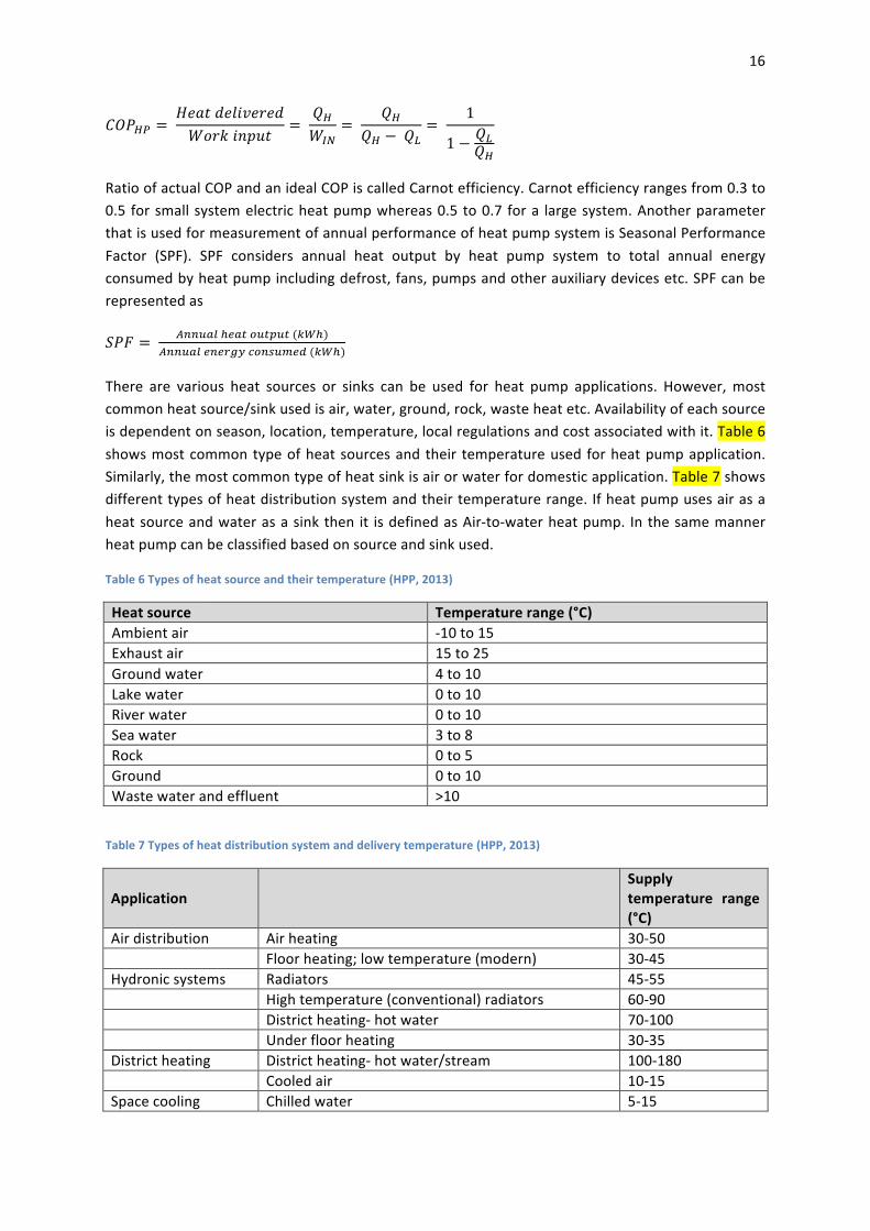
Figure22Thermalstoragetankintegratedwithheatpump
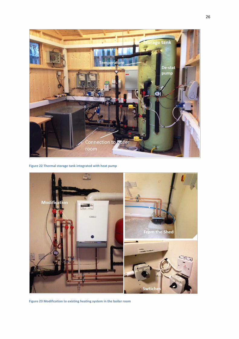
Figure23Modificationtoexistingheatingsystemintheboilerroom

27
The connection between the shed and boiler house made using underground duct work whichcarrieswater flow/return linealongwithothernecessarycablework.Themain focus isonsimpleretrofit work without replacing or disturbing existing system as much as possible. To address it,existinggasboilersystemwasbypassedandkeptasaback-upbytwonewshutoffvalveandtwonew pipes for flow and return were connected which goes to shed and connects to heatpump/storage tank. In addition, existing heating system controller also kept same and two newswitches were added to switch over between heat pump and gas boiler if heat pump fails ormaintenancework etc. Figure 23 showswork carried out in boiler room to bypass gas boiler andconnect newheat pump/storage system. The shed temperaturewasmaintained around18°C inordertoreplicateboilerhousescenariofortankheatlosses.
Inordertomonitortheperformanceofheatpump/storagesystemfollowingsensorswereplaced:
1.) Temperaturesensor:InlineandsurfacePT100(±0.2°C),2.) Flowmeter:Electromagneticflowmeter(±1%),pulsemeter(±1.5%)3.) Currenttransducer(±1%),voltagetransducer(±0.5%)andenergymeter(±1.5%)
Datawere logged24x7 intwoschedules,scheduleonerunsevery15swhereasscheduletworunsevery1minute.AlldatawereloggedbydataacquisitionsystemandstoredindedicatedPCandskydrivefordataanalysispurpose.
4.2 TestmethodologyA selected house is occupied by 3-member family and their thermal comfort is reviewedby theirfeedback during each test conditions. In addition, each room temperature and humidity wasmeasuredbydatamonitoringsysteminguardchamber.Afterinstallingallsensorsandequipment,performancedata(mainlyheatoutput)ofgasboilerwereobtainedforfirstfivedaystohavebasecasescenarioandafterthatanairsourceheatpumpreplacedgasboileron26/11/2014.Inordertoassessperformanceofheatpumpandstoragesystem,testswerecarriedoutinthreestages.
1. First stage (direct mode): Heat pump met house heating demand directly similar to gasboileroperationbetween26/11/2014to10/02/2015.
2. Secondstage(storagemode):Heatpumpprovidesheattostoragetankbasedonsetpointand storage tank meets house heating demand. This operation carried out between11/02/2015to01/04/2015.Inaddition,duringthisperiodtwosubtestscarriedoutwithde-statpumpoffandde-statpumpontounderstandimpactofstratification.
3. Thirdstage(combinedmode):Inthismode,heatpumpstoresenergyduringnighttime(i.e.2 am to 5 am) andwhen house calls for first heat (i.e. 6 am) then heat is provided fromstoragetankbasedonset-pointoncontroller.Afterthatheatpumptakesoverandprovidesheattothehouseindirectmodeforrestoftheday.Thisoperationstartedon16/04/2015onwards with possible modification in controller strategy to find optimum operationconditions.
Figure24showsschematicsoftestset-uparrangementfortheprojectwork.Heatpumphasitsownvariablespeedpump;hence,duringdirectmodeoperationitbypassedthehousepump.Forstoragemodeoperation,newpumpwasinstallednearthetankanditworkedwithhousepumpinordertomaintainsameflowrateconditionsasgasboileroperation.Inaddition,heatpumpflowtemperature

28
setat76°Cwhichwassimilartogasboilerflowtemperature. Inaddition,duringCOPcalculation,electrical energy consumption includes parasitic losses, defrost energy including standby powerconsumption and hence, it gives overall COP of the system to give realistic picture of heat pumpperformance.
Figure24Schematicsoftestsetup
Additionally,temperaturesensorforchargingordischargingtankwasinstalledatbottomcomparedto mid-position of the tank in order to store energy at higher temperature in the tank. Duringstoragemodeperformance,re-heatset-pointwassetat65°Cmeanswhenevertanktemperaturedropsbelowit,heatpumpschargesthetankandbringtemperatureto75°C.Thistemperaturewassensedbytemperatureatbottomofthetank.Duringstoragemode,twoCOPscomeintorole,firstheatpumpCOPandsecondoverallCOPwhichincludestankheatlossestoo.
Incombinedmode,one timestorageatnight timewassetat2a.m.whereheatpumpstartsandcharges tank (if temperature is lower than set point). Once temperature at bottom of the tankreaches60°C,itstopscharging.Indischarge,set-pointwassetat45°Concontroller.Thismeanswheneverhousecallsforheat, iftemperature intank isabovedischargesetpointthenitprovidesheattothehouseandstopswhentemperaturedropsbelowsetpoint.Afterthatheatpumptakesovertomeethouseheatingdemandasindirectmode.
4.3 ResultsanddiscussionDuring five months operation period of heat pump, house heat demand varied mainly due toweatherconditionsandoccupancy.Figure25showsheatingdemandvariationbetween21/11/2014to26/04/2015.Overthisperiodaverageheatdemandwasabout94kWhwithmaximumof144kWh

29
tominimumof40kWh.Higherheatdemandismainlyduetolowairtemperatureandinsomecaseshigheroccupancy.
Figure25Househeatdemandovertestperiods
Over this period heat pump performance tested in three different modes as mentioned above.Hence,heatpumpCOPvariestoo.However, justtoanalyseall threemodeperformancetogether,overall finalCOPvalueshavebeenput together forbetter comparisonpurposes. Figure26 showsvariation inoverallCOPduringall three testmodescombined for comparisonpurposes. It is clearthat the COP is higher during directmode performance compared to storagemode or combinedmode.
Figure26COPvariationsovertestperiods

30
4.3.1 DirectmodeperformanceDirectmodeperformance occurred duringwinter period (from26/11/2014 to 10/02/2015)whichincludedcoldestdaysoftheyeartoo.DuringthisperiodCOPvariedinarange1.82to2.38withanaverageof 2.07. From field trial, itwas found thatwhenair temperaturedropsbelow2°C,heatpumpstrugglestomaintainthermalcomfort.Thisoccursduetoincreasedheatlossfromthehouseatlowerambienttemperatureanddefrostsmodeoperationofheatpumpduetolowtemperatureandhumidity.
AcaseofheatpumpperformancehasbeenpresentedwhenheatpumpCOPwasthelowest(1.82).However,ambienttemperaturewasnotlowestonthatday.ItwasfoundthatheatpumpoperationtimeandheatdemandplaysimportantroleonCOPalongwithairtemperatureandhumidity.Figure27 shows flow/return temperature and room temperature on lowest COP day. Once heat pumpstartedinthemorning,itrancontinuouslytillitachievedgivenset-pointintheroom.Hence,ittooklong time to reach set-point compared to gas boiler operation. This could be due to lower heatoutputbyheatpumpinarangeof15kWcomparedto21kWbygasboiler.Figure28showsheatpumpheat output on that daywheremaximumheat output remains about 15 kWwith frequentdropsduetodefrostcycleoperationwhichcontributedinlongerheatpumpoperation.
Inaddition,heatpumpwasworkinginitsfullcapacitymeanspowerconsumptionwasalsohighest.Figure29showsvariation inpowerconsumptionduringtheday.Fullpowervariesbetween6to9kW with peak of 8.8 kW. If vast penetration of such heat pump is carried out then such powerconsumptionscenarioshouldbeconsidered inorder to find limitationandadverse impactof low-voltagenetwork(Akmal,etal.,2011)(Mancarella,etal.,2011).
Figure27Heatpumpflow/returntemperatureandroomtemperature

31
Figure28Heatoutputbyheatpumpalowestefficiencyoperationday
Figure29Heatpumppowerconsumptionatlowestefficiencyoperationday
4.3.2 StoragemodeperformanceAsmentioned previously, in storagemode, house heat demand ismet by storage tank and heatpumpgivesheattostoragetank.Duringthisprocess,significantheatlossesoccursfromstoragetankduetoenergystoredathightemperaturewhichresults in lowerCOP(overall)comparedtodirectmode.Duringstoragemode(from11/02/2015to01/04/2015),COPvariedinrangeof1.11to2.21with averageof 1.48.Another reasonbehind lowerCOP is requirementof high flow temperature(above 75°C) to charge the tank and longer running hour due to set-point and simultaneouscharging/dischargingoftank.

32
Figure30Storagemode:Heatpumpoutputwithrespecttotanktemperatureduringcharging
Figure31Storagemode:Heatpumpflow/returntemperatureandpowerconsumption

33
Figure32Storagemode:Heatoutputfromstoragetankandroomtemperature
Figure33Storagemode:Heatpumprunninghourswithde-statpumpoffandde-statpumpon
Duringstoragemode,operationwithde-statpumpoff(from11/02/2015to20/02/2015)andde-statpumpon(from21/02/2015to30/03/2015)alsoanalysed.Figure33showsbenefitofde-statpumpoperationintermsofreducedheatpumpoperatinghoursduetomoreuniformtemperatureinsidethe tank. Inaddition,heat loss fromthe tank remainsaround11kWhwhich reducesefficiencyofoverallsystem.
However, storagemode gives good performance in terms of meeting house heat demand fasterthandirectmodeperformance.Figure34showscomparisonofgasboiler,directmodeandstoragemode heat output during first 30 min of operation. As gas boiler mostly reaches desired flowtemperaturearoundfirst30minfromcoldstartinthemorning,heatoutputinfirst30minhasbeenconsideredtocompareotherperformancestoo.Gasboilergivesabout9-10kWhduringfirst30minwhereasheatpumpindirectmodegivesabout6kWh,henceittakeslongertimetoreachthermalcomfort/setpoint.Storagemodewithde-statpumpoffgivesheatoutput inarangeof8-10kWhwhichisverycomparabletogasboilerperformance.
34
Figure34Heatoutputcomparisonduringfirst30minofhouseheatdemand
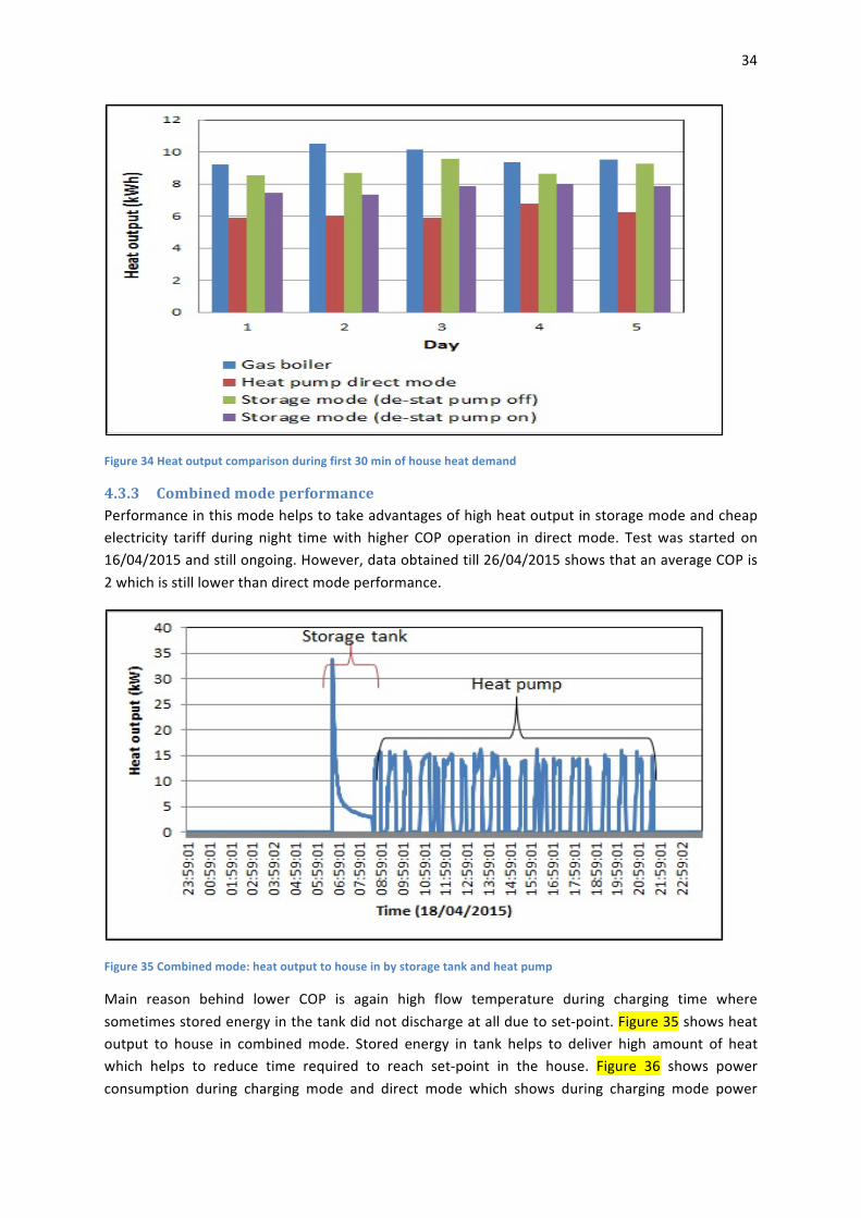
4.3.3 CombinedmodeperformancePerformanceinthismodehelpstotakeadvantagesofhighheatoutputinstoragemodeandcheapelectricity tariff during night timewith higher COP operation in directmode. Testwas started on16/04/2015andstillongoing.However,dataobtainedtill26/04/2015showsthatanaverageCOPis2whichisstilllowerthandirectmodeperformance.
Figure35Combinedmode:heatoutputtohouseinbystoragetankandheatpump
Main reason behind lower COP is again high flow temperature during charging time wheresometimesstoredenergyinthetankdidnotdischargeatallduetoset-point.Figure35showsheatoutput to house in combinedmode. Stored energy in tank helps to deliver high amount of heatwhich helps to reduce time required to reach set-point in the house. Figure 36 shows powerconsumption during charging mode and direct mode which shows during charging mode power

35
consumption varies between 2 to 4 kWwhich is far lower than standard operation. Thus, lowerpowerdemandcouldhelpelectricitygridtohandlevastdeployment/operationofsuchheatpumpduring night time. Figure 37 shows tank temperature variation during charging and discharging.Once tank temperature drops to 45°C, discharging stops and heat pump takes over as in directmode. There are still more test underway to find best suitable conditions in order to reducechargingtime,set-pointandimproveCOP.
Figure36Combinedmode:Heatpumppowerconsumptionduringcharginganddirectmode
Figure37Combinedmode:Tanktemperatureduringcharginganddischarging
4.3.4 PerformanceandcostcomparisonBasedonfieldtrialdata,heatpumpperformancewascomparedwithgasandoilboilerwithrespectto their efficiency and operating cost. For calculation, Based on themean energy use of the twohouses for thebaselineyearwhenthegasboilerwas inservice, theannualelectricitycost for the

36
heat pump system (based on an electricity standard rate of 17.18pence/kWh) will be as follows(Table8):
Table8HeatpumprunningcostwithCOP
COP Annualenergydemand(kWh) Cost(£)2.5 9095 15632.6 8745 15022.7 8421 14472.8 8121 13952.9 7841 13473.0 7579 1302AtpresentthesearespeculativeannualCOPfigures,atleastonefullyear’stestingwillberequiredtoverifyannualperformancefigures.
It should be borne in mind that the main aim of the research at Jordanstown is to assess theperformanceoftheASHPswhencombinedwiththermalstorage,inordertotakeadvantageofoff-peak electricity prices. The following plots illustrate the cost-competitiveness of ASHPs comparedwithoilandgas-firedheatingsystems,basedonthefollowingfigures;
• Simulatedannualenergydemand:27,820kWh
• Electricity:Standardrate=17.18p/kWh,
• Electricity:Economy7=8.41p/kWh
• Gas:4.41p/kWh
• Oil:38p/l(~3.8p/kWh)
Figure38HeatpumpannualrunningcostbasedonCOPandelectricitytariffs
37
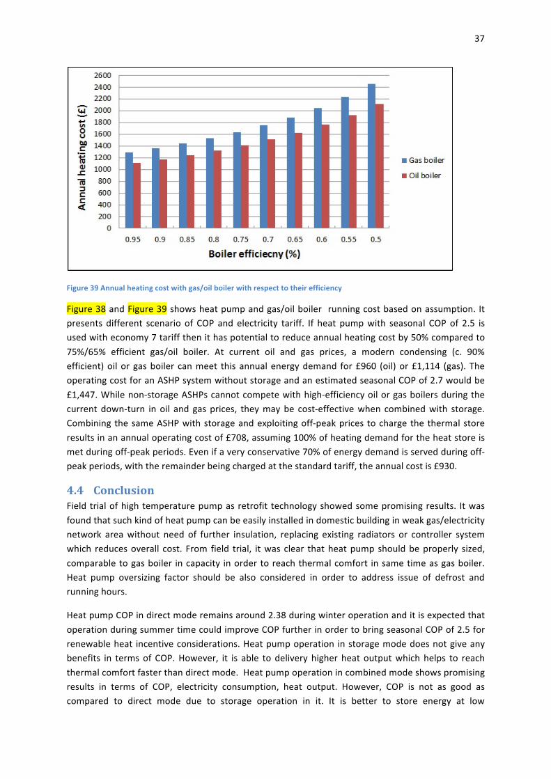
Figure39Annualheatingcostwithgas/oilboilerwithrespecttotheirefficiency
Figure38andFigure39showsheatpumpandgas/oilboiler runningcostbasedonassumption. Itpresents different scenario of COP and electricity tariff. If heat pumpwith seasonal COPof 2.5 isusedwitheconomy7tariffthenithaspotentialtoreduceannualheatingcostby50%comparedto75%/65% efficient gas/oil boiler. At current oil and gas prices, a modern condensing (c. 90%efficient)oilor gasboiler canmeet this annualenergydemand for£960 (oil)or£1,114 (gas). TheoperatingcostforanASHPsystemwithoutstorageandanestimatedseasonalCOPof2.7wouldbe£1,447.Whilenon-storageASHPscannotcompetewithhigh-efficiencyoilorgasboilersduringthecurrent down-turn in oil and gas prices, theymaybe cost-effectivewhen combinedwith storage.CombiningthesameASHPwithstorageandexploitingoff-peakprices tochargethethermalstoreresultsinanannualoperatingcostof£708,assuming100%ofheatingdemandfortheheatstoreismetduringoff-peakperiods.Evenifaveryconservative70%ofenergydemandisservedduringoff-peakperiods,withtheremainderbeingchargedatthestandardtariff,theannualcostis£930.
4.4 ConclusionFieldtrialofhightemperaturepumpasretrofit technologyshowedsomepromisingresults. Itwasfoundthatsuchkindofheatpumpcanbeeasilyinstalledindomesticbuildinginweakgas/electricitynetwork areawithout need of further insulation, replacing existing radiators or controller systemwhich reducesoverall cost. From field trial, itwas clear thatheatpumpshouldbeproperly sized,comparabletogasboiler incapacity inordertoreachthermalcomfort insametimeasgasboiler.Heat pump oversizing factor should be also considered in order to address issue of defrost andrunninghours.
HeatpumpCOPindirectmoderemainsaround2.38duringwinteroperationanditisexpectedthatoperationduringsummertimecouldimproveCOPfurtherinordertobringseasonalCOPof2.5forrenewableheat incentiveconsiderations.Heatpumpoperation instoragemodedoesnotgiveanybenefits in termsof COP.However, it is able to delivery higher heat outputwhich helps to reachthermalcomfortfasterthandirectmode.Heatpumpoperationincombinedmodeshowspromisingresults in terms of COP, electricity consumption, heat output. However, COP is not as good ascompared to direct mode due to storage operation in it. It is better to store energy at low

38
temperature by use of phase changematerial with improved heat exchange designwhichwouldhelptoreduceflowtemperatureduringchargingandhenceimproveoverallCOP.
Powerconsumptionvariationduringdirectmodegivesusefulinformationforelectricitygridpointofview. However, combined mode, night time charging shows promising result to divert peaks ofelectricity demand and reduced power consumption during that time. Such system could helpelectricitygeneratedfromrenewablestoavoidtheircurtailment(e.g.wind)withoutmuchneedoflargescalestorage.
In addition, smart controller technology is essential which predicts and/or gets real time data ofelectricity market price, wind speed, weather conditions etc., and decide right operation timeconsideringoptimumefficiencyandcostconditions.Suchcontrollerisindevelopmentanditwillbetestedwithexistingheatpumpsystemtoseerealpotentialandbenefits.
References
Akmal,M.,Fox,B.,Morrow,D.&Littler,T.,2011.Impactofhighpenetrationofheatpumpsonlowvoltagedistributionnetworks.Trondheim,PowerTech,2011IEEETrondheim.
BSI,2013.EN14511:Airconditioners,liquidchillingpackagesandheatpumpswithelectricallydrivencompressorsforspaceheatingandcooling(Part1-4),s.l.:BSI.
BSI,2014.Radiatorsandconvectors.Testmethodsandrating,s.l.:BSI.
DECC,2009.TheUKLowCarbonTransitionPlan:Nationalstrategyforclimateandenergy,Norwich:Thestationaryoffice(TSO).
DECC,2010.NationalRenewableEnergyActionPlanfortheUnitedKingdom,London:DECC.
DECC,2012a.EmissionfromHeat:StatisticalSummary,London:DepartmentofEnergy&ClimateChange.
DUKES,2012a.DigestofUnitedKingdomEnergyStatistics,London:ANationalStatisticspublicationforDepartmentofEnergyandClimateChange(DECC).
Dunbabin,P.,Charlick,H.&Green,R.,2013.DetailedanalysisfromthesecondphaseoftheEnergySavingTrust'sheatpumpfieldtrial,s.l.:DECC.
ECCA,2012.EU:Comissionforclimateaction.[Online]Availableat:http://ec.europa.eu/clima/policies/package/index_en.htm[Accessed21September2012].
Hewitt,N.,Huang,M.J.,Anderson,M.&Quinn,M.,2011.AdvancedairsoruceheatpumpforUKandEuropeandomesticbulidings.AppliedThermalEngineering,31(17-18),pp.3713-3719.
HPP,2013.HeatPumCentre.[Online]Availableat:http://www.heatpumpcentre.org/[Accessed1June2013].

39
IPCC,1990.ClimateChange:TheIPCCScientificAssessment(1990),Cambridge:CambridgeUniversityPress.
Mancarella,P.,Gan,C.&Strabac,G.,2011.EvaluationoftheimpactofelectricheatpumpsanddistributedCHPonLVnetworks.Trondheim,PowerTech,2011IEEETrondheim.
NIHE,2011.HouseConditionSurveyMainReport.[Online]Availableat:http://www.nihe.gov.uk/index/corporate/housing_research/house_condition_survey.htm[Accessed18December2014].
Palmer,J.&Cooper,I.,2011.GreatBritains'shousingenergyfactfile,London:DepartmentofEnergyandClimateChange.