Embed Size (px)
Citation preview

The Best Connections in the BusinessGeneral DataComm
'DWD&RPPV.F 28.8/33.6 Modem
Installation & Operation Manual
060R114-000 Issue 9February 2005

of this readable bject
the use mages.
Copyright©2005 General DataComm, Inc. ALL RIGHTS RESERVED.
This publication and the software it describes contain proprietary and confidential information. No part document may be copied, photocopied, reproduced, translated or reduced to any electronic or machine-format without prior written permission of General DataComm, Inc. The information in this document is suto change without notice. General DataComm assumes no responsibility for any damages arising fromof this document, including but not limited to, lost revenue, lost data, claims by third parties, or other da
If you have comments or suggestions concerning this manual, please contact:
General DataComm, Inc.Technical Publications 6 Rubber AvenueNaugatuck, Connecticut USA 06770
Telephone: 1 203 729 0271
TrademarksAll brand or product names are trademarks or registered trademarks of their respective companies or organizations.
Documentation
Revision History: GDC P/N 060R114-000
Related Publications
-REV is the hardware revision (-000 , -001 , etc.) -VREF is the most current software version (-V600 is Version 6.0.0.) In addition to the publications listed above, always read Release Notes supplied with your products.
Issue Number Date Description of Change
1 - 6 Initial Release and Product Updates.
7 November 1999 General updates and formatting
8 April 2002 General updates and corrections
9 February 2005 General updates and corrections
Description Part Number
Universal System Shelf Instruction Manual (AC and DC-to-DC Models) 010R313-REV
GDC SpectraComm 2000 Shelf Installation and Operation 010R358-REV
SpectraComm Manager Card Installation and Operation 048R303-REV
SpectraComm V.F 28.8/33.6 Modem Installation and Operation Manual 060R112-000

Table of Contents
i
i
i
3
-4
-1
3
4
4
4
5
4
5
-5
PrefaceSafety Information................................................................................................................... v
Safety Guidelines................................................................................................................ v
Compliance............................................................................................................................. vii
EC Declaration of Conformity.................................................................................................. x
Support Services and Training................................................................................................. xi
Corporate Client Services................................................................................................... xi
Factory Direct Support & Repair....................................................................................... xi
Contact Information ........................................................................................................... x
Chapter 1: IntroductionDescription............................................................................................................................. 1-1
DataComm V.F 28.8/33.6 Features....................................................................................... 1-2
Software Selection................................................................................................................. 1-
Fax.......................................................................................................................................... 1-3
Diagnostics............................................................................................................................. 1-3
Equipment List....................................................................................................................... 1
Chapter 2: InstallationUnpacking Your Modem....................................................................................................... 2-1
Option Jumpers...................................................................................................................... 2
DTE Interface Cards.........................................................................................................2-
Installation Procedure............................................................................................................ 2-
Enclosure/Shelf Installation..............................................................................................2-4
Modem Installation...........................................................................................................2-
Electrical Connections........................................................................................................... 2-
DTE Cables....................................................................................................................2-1
Special Considerations for High Data Rates........................................................................ 2-15
Verifying Your Connections................................................................................................ 2-16
Chapter 3: OperationFront Panel Controls and Indicators....................................................................................... 3-1
Operating Procedures............................................................................................................. 3-
Status................................................................................................................................3-4
Configuration....................................................................................................................3-
Diagnostics.......................................................................................................................3
060R114 -000 GDC DataComm V.F 28.8/33.6 Modem iIssue 9 Installation and Operation Manual

Table of Contents
-7
1
6
7
8
1
4
5
5
6
8
Call Control...................................................................................................................... 3
Completing a Connection............................................................................................... 3-10
Call Answering - Automatic.......................................................................................... 3-10
Call Answering - Manual............................................................................................... 3-10
Disconnecting a Call...................................................................................................... 3-11
Automatic Calling Unit (ACU) Support.............................................................................. 3-11
MI/MIC Operation............................................................................................................... 3-1
SteadFast Security Password............................................................................................... 3-12
On-Line Password Security........................................................................................... 3-13
Command Mode and Data Mode......................................................................................... 3-16
AT Command Mode............................................................................................................ 3-1
Configuration Profiles.................................................................................................... 3-17
Command Syntax........................................................................................................... 3-1
Command Buffer............................................................................................................ 3-1
Remote Configuration Using the AT Commands.......................................................... 3-18
Data Mode........................................................................................................................... 3-9
Asynchronous Operation..................................................................................................... 3-20
Automatic DTE Speed and Parity Detection................................................................. 3-20
Error Correcting Modes................................................................................................. 3-21
MNP Reliable Mode Error Correction........................................................................... 3-22
MNP Reliable Mode with Data Compression................................................................ 3-23
V.42 (LAPM) Reliable Mode Error Correction............................................................. 3-23
V.42 bis Data Compression........................................................................................... 3-23
V.42 (LAPM)/MNP Auto-reliable Mode....................................................................... 3-23
V.42/MNP Reliable Mode............................................................................................. 3-24
Non-Error Correcting Modes......................................................................................... 3-24
Wire Mode..................................................................................................................... 3-2
Direct V.14 Asynchronous Mode.................................................................................. 3-24
V.13 Mode..................................................................................................................... 3-2
Flow Control.................................................................................................................. 3-2
Synchronous Operation....................................................................................................... 3-2
Synchronous Operating Modes...................................................................................... 3-26
Asynchronous Dialing with Synchronous Transmission............................................... 3-26
Direct Dialing in Synchronous Mode............................................................................ 3-26
Normal Synchronous Mode........................................................................................... 3-27
V.13 Synchronous Mode................................................................................................ 3-27
Synchronous Compression Mode.................................................................................. 3-27
Clock Selection.............................................................................................................. 3-2
Switched Network Operation.............................................................................................. 3-28
ii GDC DataComm V.F 28.8/33.6 Modem 060R114-000Installation and Operation Manual Issue 9

Table of Contents
8
9
9
0
0
1
2
-1
-1
2
4
-4
9
0
Telephone Lines.............................................................................................................3-2
Private Line Operation......................................................................................................... 3-2
Two-wire or Four-wire Selection...................................................................................3-29
Other Configuration........................................................................................................3-2
Transmit Level................................................................................................................3-3
Automatic and Manual Handshaking.............................................................................3-30
Auto Dial Restoral..........................................................................................................3-3
Testing the Modem.............................................................................................................. 3-3
Chapter 4: AT Command Set OperationCommanding the Modem....................................................................................................... 4-1
Setup Procedures..............................................................................................................4-
AT Command Reference..................................................................................................... 4-11
Chapter 5: V.25 bis Command Set Operation108 Modes.............................................................................................................................. 5-1
108.2 Mode.......................................................................................................................5
108.1 Mode.......................................................................................................................5
Operating Procedures............................................................................................................. 5-
Commanding the Modem....................................................................................................... 5-2
V.25 bis Configuration Commands....................................................................................... 5-4
V.25 bis Communication Commands.................................................................................... 5-7
ITU-T V.25 bis Communication Operating Procedures....................................................... 5-9
108.2 Mode Operating Procedures...................................................................................5-9
108.2 Call Establishment Procedure...............................................................................5-10
108.1 Mode Operating Procedures.................................................................................5-11
V.25 bis 108.2 Mode Interface Specifications..................................................................... 5-12
Interface Connections.....................................................................................................5-12
Synchronous Format Selection.......................................................................................5-12
Asynchronous Format....................................................................................................5-13
Modem Test Modes........................................................................................................5-1
Chapter 6: TestsAnalog Loopback (ANALOOP)............................................................................................ 6-2
Analog Loopback with Self-Test........................................................................................... 6-3
Digital Loopback.................................................................................................................... 6
Remote Digital Loopback...................................................................................................... 6-5
Remote Digital Loopback with Self-Test.............................................................................. 6-7
End-to-End Self-Test............................................................................................................. 6-
RDLB Requests.................................................................................................................... 6-1
060R114-000 GDC DataComm V.F 28.8/33.6 Modem iiiIssue 9 Installation and Operation Manual

Table of Contents
Appendix A: Technical Specifications
Appendix B: Business Equipment Interface ( TIA/EIA-232-F, ITU-T V.24/V.28/ISO 2110)
Appendix C: Business Equipment Interface EIA/TIA-530-A (ITU-T V.10/V.11/V.24/ISO 2110)
Appendix D: Business Equipment Interface ( V.35, ITU-T V.24/V.28/V.35/ISO 2593)
Appendix E: ASCII Character Set
iv GDC DataComm V.F 28.8/33.6 Modem 060R114-000Installation and Operation Manual Issue 9

m is tion, al uct.
he
Preface
Scope
This manual describes how to install and operate the GDC V.F 28.8/33.6 modem (DataComplatform version). The information contained in this manual has been carefully checked andbelieved to be entirely reliable. However, as General DataComm improves the reliability, funcand design of their products, is possible that information may not be current. Contact GenerDataComm if you require updated information for this or any other General DataComm prod
General DataComm, Inc.Technical Publications Department6 Rubber AvenueNaugatuck, Connecticut, USA 06770Tel: 1 203 729-0271
Manual Organization
The online (web-based) manual uses links which allow you to navigate through portions of tmanual by clicking on any blue text. This manual is divided into the following chapters:
Chapter 1, Introduction
Chapter 2, Installation
Chapter 3, Operation
Chapter 4, AT Command Set Operation
Chapter 5, V.25 bis Command Set Operation
Chapter 6, Tests
Appendix A, Technical Specifications
Appendix B, Business Equipment Interface (TIA/EIA-232-F, ITU-T V.24/V.28/ISO 2110)
Appendix C, Business Equipment Interface EIA/TIA-530-A (ITU-T V.10/V.11/V.24/ISO 2110)
Appendix D, Business Equipment Interface (V.35, ITU-T V.24/V.28/V.35/ISO 2593)
Appendix E, ASCII Character Set
060R114-000 DataComm V.F 28.8/33.6 Modem vIssue 9 Installation and Operation Manual

Preface Safety Information
rior to elow.
re tor. for .2,
d.tion.
puter atic hat are l when
ring ents,
ly
ot
in
n
Safety InformationThis manual should be read in its entirety and all procedures completely understood beforeinstalling or operating the unit. The notes that appear throughout this manual must be read pany installation or operating procedure. Examples of notes used in this manual are shown b
The CAUTION, WARNING, and DANGER statements that appear throughout this manual aintended to provide critical information for the safety of both the service engineer and operaThese statements also enhance equipment reliability. The following definitions and symbolsCAUTION, WARNING, and DANGER as they are used in this manual comply with ANSI Z535American National Standard for Environmental and Facility Safety Signs, and ANSI Z535.4,Product Safety Signs and Labels, issued by the American National Standards Institute.
Safety GuidelinesWhen unsafe conditions exist or when potentially hazardous voltages are present:
• Always use caution and common sense.• Repairs must be performed by qualified service personnel only.• To reduce the risk of electrical shock, do not operate equipment with the cover remove• Never install telephone jacks in a wet location unless the jack is designed for that loca• Never touch uninsulated telephone wires or terminals unless the telephone line is
disconnected at the network interface.• Never install telephone wiring during an electrical storm.
Antistatic Precautions
Electrostatic discharge (ESD) results from the buildup of static electricity and can cause comcomponents to fail. Electrostatic discharge occurs when a person whose body contains a stbuildup touches a computer component. This product may contain static-sensitive devices teasily damaged. Proper handling, grounding and precautionary ESD measures are essentiainstalling parts or cards. Keep parts and cards in antistatic packaging when not in use or dutransport. If possible, use antistatic floorpads and workbench pads. When handling componalways use an antistatic wrist strap connected to a grounded equipment frame or chassis. If a wrist strap is not available, periodically touch an unpainted metal surface on the equipment. Never use a conductive tool, like a screwdriver or a paper clip, to set switches.
Note A note provides essential operating information not readily apparent which you should be particularaware of. A note is typically used as a suggestion.
Important Indicates an emphasized note. It is something you should be particularly aware of; something nreadily apparent. Important is typically used to prevent equipment damage.
CAUTION indicates conditions or practices that can cause damage to equipment or loss of data.
WARNING indicates a potentially hazardous situation which, if not avoided, may result minor to moderate injury. It may also be used to alert against unsafe practices.
DANGER indicates an imminently hazardous situation which, if not avoided, will result ideath or serious injury.
vi DataComm V.F 28.8/33.6 Modem 060R114-000Installation and Operation Manual Issue 9

Preface Compliance
by ch
vides e the
ne ot laint mpany d the
o
use
s as e
to the ing an above
upplier. y give
wer ether.
Compliance
Part 68 ComplianceConnection of data communications equipment to the public telephone network is regulatedFCC Rules and Regulations. This equipment complies with Part 68 of these regulations whirequire all of the following:
All connections to the telephone network must be made using standard plugs and telephonecompany provided jacks or equivalent. Connection of this equipment to party lines and cointelephones is prohibited. A label on the component side of the unit’s printed circuit board prothe FCC Registration number for the unit. If requested, give this information to the telephoncompany. To connect the product to the Public Telephone Network, you are required to givefollowing information to the telephone company:
• FCC Registration Number: AG6USA-75852-MD-E 0.4B
• Facility Interface Codes:
• Service Order Code:
• Telephone Company jack type: RJ45S, RJ11C
The telephone company may discontinue your service if the unit causes harm to the telephonetwork. If possible, you will be notified of such an action in advance. If advance notice is npractical, you will be notified as soon as possible and will be advised of your right to file a compwith the FCC. The telephone company may change its communication facilities, equipment,operations and procedures where reasonably required for operation. If so, the telephone cowill notify you in writing. All repairs or modifications to the equipment must be performed byGeneral DataComm. Any other repair or modification by a user voids the FCC registration anwarranty.
Part 15 ComplianceThis device complies with Part 15 of the FCC rules. Operation is subject to the following twconditions:
1. This device may not cause harmful interference and2. This device must accept any interference received, including interference that may ca
undesired operation.
Industry Canada NotificationThe Industry Canada label identifies certified equipment. This certification means that the equipment meets telecommunications network protective, operation and safety requirementprescribed in the appropriate Terminal Equipment Technical Requirements document(s). ThDepartment does not guarantee the equipment will operate to the user's satisfaction.
Before installing this equipment, users should ensure that it is permissible to be connected facilities of the local telecommunications company. The equipment must also be installed usacceptable method of connection. The customer should be aware that compliance with the conditions may not prevent degradation of service in some situations.
Repairs to certified equipment should be coordinated by a representative designated by the sAny repairs or alterations made by the user to this equipment, or equipment malfunctions, mathe telecommunications company cause to request the user to disconnect the equipment.
Users should ensure for their own protection that the electrical ground connections of the poutility, telephone lines and internal metallic water pipe system, if present, are connected tog
060R114-000 DataComm V.F 28.8/33.6 Modem viiIssue 9 Installation and Operation Manual

Preface Compliance
ct the
n rface. e
ceed 5.
e ues
ra à la
llé en ble que dans
é par le r un
de
source a, sont les.
voir as.
e le ’une e de
This precaution may be particularly important in rural areas.
Caution: Users should not attempt to make such connections themselves, but should contaappropriate electric inspection authority, or electrician, as appropriate.
Notice: The Ringer Equivalence Number (REN) assigned to each terminal device provides aindication of the maximum number of terminals allowed to be connected to a telephone inteThe termination on an interface may consist of any combination of devices subject only to threquirement that the sum of the Ringer Equivalence Numbers of all the devices does not ex
Electromagnetic Compatibility
This Class A digital apparatus complies with Canadian ICES-003.
Avis D’industrie Canada
L’étiquette d’Industrie Canada identifie le matériel homologué. Cette étiquette certifie que le matériel est conforme aux normes de protection, d’exploitation et de sécurité des réseaux dtélécommunications, comme le prescrivent les documents concernant les exigences techniqrelatives au matériel terminal. Le Ministère n’assure toutefois pas que le matériel fonctionnesatisfaction de l’utilisateur.
Avant d’installer ce matériel, l’utilisateur doit s’assurer qu’il est permis de le raccorder aux installations de l’entreprise locale de télécommunication. Le matériel doit également être instasuivant une méthode acceptée de raccordement. L’abonné ne doit pas oublier qu’il est possila comformité aux conditions énoncées ci-dessus n’empêche pas la dégradation du servicecertaines situations.
Les réparations de matériel homologué doivent être coordonnées par un représentant désignfournisseur. L’entreprise de télécommunications peut demander à l’utilisateur de débrancheappareil à la suite de réparations ou de modifications effectuées par l’utilisateur ou à causemauvais fonctionnement.
Pour sa propre protection, l’utilisateur doit s’assurer que tous les fils de mise à la terre de la d’énergie électrique, des lignes téléphoniques et des canalisations d’eau métalliques, s’il y enraccordés ensemble. Cette précaution est particulièrement importante dans les régions rura
Avertissement: L’utilisateur ne doit pas tenter de faire ces raccordements lui-même; il doit arecours à un service d’inspection des installations électriques, ou à un électricien, selon le c
Avis: L’indice d’équivalence de la sonnerie (IES) assigné à chaque dispositif terminal indiqunombre maximal de terminaux qui peuvent être raccordés à une interface. La terminaison dinterface téléphonique peut consister en une combinaison de quelques dispositifs, à la seulcondition que la somme d’indices d’équivalence de la sonnerie de tous les dispositifs n’excèpas 5.
La Compatibilité d’ Eléctro-magnetique
Cet appareil numerique de la classe A est conforme a la norme NMB-003 du Canada.
viii DataComm V.F 28.8/33.6 Modem 060R114-000Installation and Operation Manual Issue 9

Preface Compliance
owohl er , r heits-
r
t daf
ht of-n.
Deutschland
Überblick Sicherheit
Bitte lesen sie dieses Handbuch komplett durch und stellen sie sicher, daß sie alle Vorschriften verstehen, bevor sie das Gerät installieren oder betreiben. Die Hinweise in diesem Handbuch müssen vor Installation oder Betrieb gelesen werden. Beispiele für Hinweise sehen sie hier.
Die Hinweise CAUTION (VORSICHT), WARNING (WARNUNG) und DANGER (GEFAHR),welche im Handbuch erscheinen, enthalten entscheidende Informationen für die Sicherheit sdes Servicepersonals als auch der Bediener. Diese Hinweise erhöhen die Zuverlässigkeit dAnlage. Die folgenden Definitionen und Symbole für VORSICHT, WARNUNG und GEFAHRwie sie in diesem Handbuch auftreten, sind gemäß ANSI Z535.2, Amerikanischer NationaleStandard für Sicherheitszeichen für Umwelt und Anlagen, und ANSI Z535.4, Produkt-SicherZeichen und Beschriftungen, ausgegeben vom American National Standards Institute.
Sicherheitsrichtlinien
Unter normalen Umständen arbeitet die Anlage sicher und zuverlässig in ihrem Netzwerk. FalscheHandhabung oder Installation von Bestandteilen kann zu Ausfällen oder Gefahren für den Bediener führen. Seien sie vorsichtig und beachten sie die allgemeinen Regeln bei der Installation deNetzwerkkabel. Beachten sie die folgenden Hinweise, besonders bei unsicheren Umständen oder potentiell gefährlichen Spannungen:
• Reparaturen dürfen nur von qualifiziertem Servicepersonal ausgeführt werden.
• Zur Vermeidung elektrischer Schläge darf die Anlage nicht mit geöffneter Abdeckung betrieben werden.
• Niemals Netzwerkstecker in feuchter Umgebung installieren, es sei denn der Stecker isür ausgelegt.
• Niemals unisolierte Netzwerkdrähte oder Klemmen berühren, es sei denn das Netwerk ist amInterface abgeschaltet.
• Niemals Netzwerk bei elektrischem Gewitter verdrahten.
Hinweis Ein Hinweis enthält wichtige Informationen zum Betrieb, die nicht auf den ersten Blick ersichtlichsind, und die zu beachten sind. Ein Hinweis dient als Vorschlag.
Wichtig Bedeutet einen besonders wichtigen Hinweis. Darauf sollten sie besonders achten, da dies nicfensichtlich ist. Wichtige Hinweise dienen im Allgemeinen dazu, Schäden am Gerät zu vermeide
VORSICHT bedeutet eine potentiell gefährliche Situation, die wenn sie nicht vermieden wird, zu leichten oder mittelschweren Verletzungen führen kann.
WARNUNG bedeutet eine drohende gefährliche Situation, die wenn sie nicht vermieden wird, zu schweren Verletzungen oder zum Tode führen kann.
GEFAHR bedeutet eine drohende gefährliche Situation, die wenn sie nicht vermieden wird,zwangsläufig zu schweren Verletzungen oder zum Tode führt.
060R114-000 DataComm V.F 28.8/33.6 Modem ixIssue 9 Installation and Operation Manual

Preface EC Declaration of Conformity
ournal
e
EC.
EC Declaration of ConformityWe: General DataComm Inc.
6 Rubber AvenueNaugatuck, CT 06770, U.S.A.
The products to which this declaration relates are in conformity with the following relevant harmonized standards, the reference numbers of which have been published in the Official Jof the European Communities.
Electromagnetic Compatibility
EN 55022: 1994
Specification for limits and methods of measurement of radio interference characteristics ofinformation technology equipment.
EN 50082-1: 1992
Generic immunity standard Part 1 Residential, Commercial, and Light Industry.
Safety
EN 60950: 1995 A1 through A3
Low Voltage Directive relating to electrical equipment designed for use within certain voltaglimits.
Communications
CTR 15
CTR17
Following the provisions of the Telecommunications Terminal Equipment Directive, 98/13/E
x DataComm V.F 28.8/33.6 Modem 060R114-000Installation and Operation Manual Issue 9

Preface Support Services and Training
re-and
nt, ck,
omers f GDC DC
nd ff used port the
anges n the
Support Services and Training
General DataComm offers two comprehensive customer support organizations dedicated to ppost-sale support services and training for GDC products. Corporate Client Services and Factory-Direct Support & Repair assist customers throughout the world in the installation, managememaintenance and repair of GDC equipment. Located at GDC’s corporate facility in NaugatuConnecticut USA, these customer support organizations work to ensure that customers getmaximum return on their investment through cost-effective and timely product support.
Corporate Client Services
Corporate Client Services is a technical support and services group that is available to GDC customers throughout the world for network service and support of their GDC products. Custget the reliable support and training required for installation, management and maintenance oequipment in their global data communication networks. Training courses are available at Gcorporate headquarters in Naugatuck, Connecticut, as well as at customer sites.
Factory Direct Support & Repair
GDC provides regular and warranty repair services through Factory Direct Support & Repair at its U.S. headquarters in Naugatuck, Connecticut. This customer support organization repairs arefurbishes GDC products, backed by the same engineering, documentation and support stato build and test the original product. Every product received for repair at Factory Direct Sup& Repair is processed using the test fixtures and procedures specifically designed to confirmfunctionality of all features and configurations available in the product.
As part of GDC’s Factory Direct program, all product repairs incorporate the most recent chand enhancements from GDC Engineering departments, assuring optimal performance whecustomer puts the product back into service. Only GDC’s Factory Direct Support & Repair can provide this added value.
Contact Information
General DataComm, Inc.6 Rubber AvenueNaugatuck, Connecticut 06770 USAAttention: Corporate Client Services
Telephones: 1 800 523-1737 1 203 729-0271Fax: 1 203 729-3013Email: [email protected]
General DataComm, Inc.6 Rubber AvenueNaugatuck, Connecticut 06770 USAAttention: Factory Direct Support & Repair
Telephones: 1 800 523-1737 1 203 729-0271Fax: 1 203 729-7964Email: [email protected]
Hours of Operation: Monday - Friday 8:30 a.m. - 5:00 p.m. EST
(excluding holidays)
http://www.gdc.com
060R114-000 DataComm V.F 28.8/33.6 Modem xiIssue 9 Installation and Operation Manual

Preface Support Services and Training
xii DataComm V.F 28.8/33.6 Modem 060R114-000Installation and Operation Manual Issue 9

e used nostics.
vides F) line.
eration ration is m's
ed
local n nd
unt up
ics are
Chapter 1: Introduction
OverviewThis chapter of the DataComm V.F 28.8/33.6 modem Installation and Operation Manual describes and lists the features of the product. It describes information on communication software to bin a personal computer connected to the modem, and a brief description of the modem’s diag
DescriptionThe DataComm V.F 28.8/33.6 modem is a universal, full-duplex, multi-speed modem that pro33.6 kbps to 300 bps operation (depending on the modulation scheme) over the telephone (VIt can be connected to a 2-wire switched line, a 2-wire private line, or a 4-wire private line.
The modem can support asynchronous or synchronous DTE data rates up to 128 kbps. Opcan be either synchronous or character asynchronous at all speeds down to 1200 bps. Opeasynchronous at 0 to 300 bps. Synchronous rates above 28.8 kbps require use of the modesynchronous data compression feature.
The modem supports the following protocols:
• V.42 (LAPM) error correction
• V.42 bis data compression
• MNP-2 through MNP-4 error correction
• MNP-5 data compression
• ITU-T (formerly CCITT) V.32, V.32 bis, V.22, V.22 bis, V.21
• Bell 212A and Bell 103 specifications
The V.F 28.8/33.6 provides automatic dial (AT Command) and automatic answer for switchnetwork operation. It also supports 2- and 4-wire private line operation.
The V.F 28.8/33.6 can be controlled in a number of ways. It can accept commands from its DTE using either the AT command set or the ITU-T V.25 bis command set. The AT commands caalso be used for remote configuration performed through an off-site V.F 28.8/33.6 modem aDTE. The modem includes front panel controls for configuration and testing.
You can install the V.F 28.8/33.6 in a standalone DataComm Enclosure, or you can rackmoto 16 units in a DataComm Shelf or Universal System Shelf.
The V.F 28.8/33.6 modem is available in a variety of models. Table 1-1 lists the part numbers for theV.F 28.8/33.6's standard and optional equipment. The V.F 28.8/33.6's technical characteristdescribed in Appendix A, Technical Specifications.
V.F. 28.8 TR SD RD MR RS CS CO GD TM ALM OH
AL ST RDL DL SEL D/TK
ADV
060R114-000 DataComm V.F 28.8/33.6 Modem 1-1Issue 9 Installation and Operation Manual

Introduction DataComm V.F 28.8/33.6 Features
it
DataComm V.F 28.8/33.6 Features• Integral synchronous/asynchronous operation.
• Synchronous DTE rates to 33.6 kbps.
• Asynchronous DTE rates to 128 kbps.
• 2-wire, full-duplex, switched network operation with programmable or permissive transmlevels.
• 2- or 4-wire private line operation, with selectable transmit level.
• Automatic VF line rate determination in V.32 bis modes, with fallforward/fallback.
• Auto Dial Restoral to restore a failed private line link over the switched network.
• V.42/MNP error control.
• V.42 bis/MNP-5 asynchronous data compression.
• Synchronous data compression (supports rates up to 128 kbps).
• EIA/TIA-602 "AT" Command Set support.
• V.25 bis compatible command protocol support
• Remote Configuration to change a remote modem’s user configuration profile
• Front panel push buttons and Electronic Display Window for configuration and testing.
• Eleven front panel status LEDs.
• MI/MIC support to allow a 503/2503-type telephone to function as a talk/data switch
• Flash memory for downloading modem firmware.
• Permanent storage of modem configuration profiles in non-volatile memory.
• External, Internal, or Receiver Recovered transmit timing.
• Maximum line rate selection.
• Asynchronous character lengths of 8, 9, 10, and 11 bits.
• Password security
• Security Callback to prevent unauthorized access to a remote modem
• Intelligent Serial Terminal Dialer via the DTE interface, using the EIA/TIA-602 "AT" Command Set.
• Stores up to ten telephone numbers for easy dialing.
• Pulse or tone dialing.
• Support for the DataComm 801A/C Automatic Calling Unit
• Manual or automatic answer.
• Analog Loopback with and without Self-Test features.
• Digital Loopback and Remote Digital Loopback.
1-2 DataComm V.F 28.8/33.6 Modem 060R114-000Installation and Operation Manual Issue 9

Introduction Software Selection
e and
llows grams
rt disk
res. Of aster.
hould nd to be
cols g ed for
ption.
ay of -Test, End ont T
the
• End-to-End Self-Test (511 or in FSK ALT pattern).
• Front panel lockout.
• Optional ITU-T V.35 and EIA RS-530A DTE interfaces.
• Up to 16 modems per shelf.
• Supports FAX Class 1 operation using V.27 or V.29 modulation.
Software Selection
There are two types of computer software for use with a modem: terminal emulation softwardata communications software.
Terminal emulation software essentially "downgrades" your computer to a dumb terminal. It ayou to type at the keyboard and see responses on the video display or printer. Emulation proare often used to communicate with main-frame or mini-computers, and usually do not suppomanagement or file transfers.
A full-featured data communications software package does allow file transfers, as well as providing a dial directory, a script language for automated sessions, and a host of other featucourse, the more powerful and flexible a software package is, the more difficult it may be to m
To take full advantage of the features of the V.F 28.8/33.6 modem, your selected program sallow turning off the autobaud feature. You should also be able to toggle both XON/XOFF ahardware flow control. In addition, it should support several file transfer protocols designed used with an error-correcting modem.
Although your modem will work with most standard communications programs and file protosuch as XMODEM, there may be a throughput penalty when using a software error-detectinprotocol due to the redundant error-checking overhead. File transfer protocols that are tailoruse with error-correcting modems are YMODEM-G and IMODEM.
Fax
The modem (Revision G software and later) can support FAX Class 1 transmission and receThe function requires use of ITU-T V.27 or V.29 modulation and Class 1 PC software.
Diagnostics
To help you restore service quickly in the event of problems, the V.F 28.8/33.6 offers an arrdiagnostics for accurate detection of system faults. Included are Local Loop, Local Loop SelfDigital Loopback, Remote Digital Loopback, Remote Digital Loopback Self-Test, and End-to-Self-Test. Most tests can be controlled by front panel switches and monitored through the frpanel display and LEDs. Tests may also be controlled from a terminal or computer, using Acommands.
Note Before you load and activate the FAX software, make sure that the modem is connected toPC and switched On.
060R114-000 DataComm V.F 28.8/33.6 Modem 1-3Issue 9 Installation and Operation Manual

Introduction Equipment List
Equipment List
Table 1-1 Equipment List
Description GDC Part No. Notes
V.F 28.8/33.6 Printed Circuit (pc) Cards
DataComm V.F 28.8/33.6 rackmount pc card, with TIA/EIA-232-F DTE interface
060P014-001
DataComm V.F 28.8/33.6 rackmount pc card, with 530-A interface card 060M014-301
DataComm V.F 28.8/33.6 rackmount pc card, with V.35 DTE interface card 060M014-201
DataComm V.F 28.8/33.6 standalone, 117 V ac, with 232-E DTE interface 060A014-001
DataComm V.F 28.8/33.6 standalone 117 V ac, with 530-A DTE interface card 060A014-301
DataComm V.F 28.8/33.6 standalone, 117 V ac, with V.35 DTE interface card 060A014-201
DTE interface card, 530-A 060P017-001 R, S
DTE interface card, V.35 060P016-001 R, S
Miscellaneous Equipment
DataComm 801A/C pc card assembly 064P002-001 R
GDC 801A/C Standalone Automatic Calling Unit 064A001-001 S
Rackmount DataComm Shelves
Model DS-1, 117 V ac 010B015-001 R
Model DS-5NR, dc, nonredundant power supply 010M011-002 R
Model DS-5R, dc, redundant power supply 010M011-001 R
Model DS-6N/R, dc, nonredundant power supply, NEBS compliant 010M047-002 R
Model DS-6R, dc, redundant power supply, NEBS compliant 010M047-001 R
Rackmount Universal System Shelves
Model USS-1-D, 117 V ac 010B080-001 R
Model USS-1-DC/NR, dc, nonredundant power supply 010M040-001 R
Model USS-1-DC/R, dc, redundant power supply 010M040-002 R
DC-1, domestic DataComm backplane for Universal System Shelf, models USS-1-D, USS-1-DC/NR, and USS-1-DC/R
010B081-001 R
Standalone DataComm Enclosure
Base assembly, Model DE-1, 117 V ac 010B017-001 S*
Cover 010D500-003 S*
NOTES: R Rackmount option.S Standalone option.S* Included with A-level standalone models.
(Sheet 1 of 2)
1-4 DataComm V.F 28.8/33.6 Modem 060R114-000Installation and Operation Manual Issue 9

Introduction Equipment List
Cables
801 ACU switched network cable 064H001-001 R, S
801 ACU switched network cable, permissive, model CPE-D-14 024H515-014 R, S
801 ACU-to-modem cable 064H001-001 R, S
Adapter, 25-pin female TIA/EIA-232-F to two phone jacks 209-036-002 R
DTE cable adapter, TIA/EIA-232-F (25-pin male) to V.35 (34-pin female) 027H572-001 R, S
DTE cable, TIA/EIA-232-F, 19.2 to 128 kbps (maximum length of 5 feet) 028H511-005 R, S
DTE cable, EIA/TIA-530-A 027H525-XXX R, S
DTE cable, male-to-male straight through, DB25-DB25, 25 pins 028H502-025 R, S
Private line cable, 8-pin modular-to-lugs 024H122-XXX R, S*
Private line cable, model D25S 023H101-XXX R, S
Switched network cable, 8-pin modular-to-lugs 830-029-8XX R
Switched network cable, permissive, model CPE-M 830-027-4XX R, S*
Switched network cable, programmable, model CPR-M 830-028-8XX R, S*
Telephones
500 telephone, standard desk model with rotary dial 950-114-110 R, S
503 telephone, modified rotary dial model supplied by Telco
R, S
2500 telephone, standard desk model with push-button DTMF dial 950-114-111 R, S
2503 telephone, modified push-button dial model supplied by Telco
R, S
Manuals
DataComm 801A/C Automatic Calling Unit 064R101-000 S
DataComm Shelf, Model DS-1 010R310-000 R
DataComm Shelf, Model DS-5 010R340-000 R
DataComm Shelf, Model DS-6 010R341-000 R
Universal System Shelf, Models USS-1-D, E, J, and U 010R380-000 R
Universal System Shelf, Models USS-1-DC/NR and USS-1-DC/R 010R385-000 R
Table 1-1 Equipment List (Continued)
Description GDC Part No. Notes
NOTES: R Rackmount option.S Standalone option.S* Included with A-level standalone models.
(Sheet 2 of 2)
060R114-000 DataComm V.F 28.8/33.6 Modem 1-5Issue 9 Installation and Operation Manual

Introduction Equipment List
1-6 DataComm V.F 28.8/33.6 Modem 060R114-000Installation and Operation Manual Issue 9

en you
Chapter 2: Installation
OverviewThis section describes installation of the V.F 28.8/33.6 modem.
Unpacking Your ModemThe unit is shipped enclosed in a box and protected by packing material. Inspect the unit whreceive it. Notify the shipper of any damage immediately.
Keep the box and packing material to use if you ever need to reship the unit.
Option JumpersThe V.F 28.8/33.6 has four factory-set option jumpers. Verify that they are set as shown in Figure 2-1 and described in Table 2-1.
060R114-000 DataComm V.F 28.8/33.6 Modem 2-1Issue 9 Installation and Operation Manual

Installation Option Jumpers
Figure 2-1 DataComm V.F 28.8/33.6 Card Layout
060P014-001
J3 J2
Phone Line
J1
R T R T
RX4WPL
TX2WPL
RL1TB1 O
PE
N
SE
P X4
CO
M
X7 1
212
11 X6 1
212
11
SN
-MIM
IC-P
RP
C
4W P
L
SN
-4WP
L
X8 1
212
11
NOTE: jumpers X6, X7, and X8 apply onlywhen the card is installed in a DataComm Shelf.
XA
2J2 D
TE Interface C
ard
CC
ITT V.24/V
.28/V.35/IS
O 2593 (V
.35): 069P016-001
CC
ITT V.10/V
.11/V.24/IS
O 2110 (E
IA/TIA
-530-A): 060P
017-001
XA
2J2
XA
2J2X
A2J2
X11
600
900
X5
DIS
ENX14
1
3
XY
G
VF 28.8 Basecard
F1F2
NOTE: Options are selected as shipped from the factory for USA version
NOTE: The built-in CCITT V.24/V.28/ISO 2110 (TIA/EIA-232-F)interface does not use a DTEinterface card.
MPMC
X15
BD
TES
T
2-2 DataComm V.F 28.8/33.6 Modem 060R114-000Installation and Operation Manual Issue 9

Installation Option Jumpers
2J3,
crew is
he DTE
can r 1
Table 2-1 Option Jumpers
DTE Interface Cards
The V.F 28.8/33.6 has a built-in TIA/EIA-232-F (ITU-T V.24/V.28/ISO 2110) DTE interface. There are two other DTE interfaces available that each require a unique plug-in card:
• V.35 (ITU-T V.24/V.28/V.35/ISO 2593)
• EIA/TIA-530-A (ITU-T V.10/V.11/V.24/ ISO 2110 Amendment 1)
The DTE interface card attaches to the modem base card via connectors XA2JI, XA2J2, XAand XA2J4 as illustrated in Figure 2-1. The DTE interface cards have no option jumpers.
To remove/insert a DTE interface card:
1. Remove the machine screw and washer that hold the DTE interface card in place. The slocated in the center of the bottom of the modem base card.
2. Pull the DTE interface card straight out to avoid bending its pins.
3. Orient the DTE interface card as shown in Figure 2-1. The 13-pin connectors are on the left side of the card when viewed from the back.
4. Press on the DTE interface card evenly to avoid bending its pins.
5. Insert the machine screw and washer, then gently tighten the screw to seat and secure tinterface card.
Jumper Position Description
X4 OPEN * Opens frame (chassis) and signal (reference) grounds.
COM Commons frame and signal grounds (connected through fusible link FL1).
SEP Separates (isolates) frame and signal grounds by 100 ohm.
X5 DIS* MUST be in the DIS position.
X6 all pins covered Selects private line (four-wire or two-wire) only operation. **
X7 all pins covered* Selects switched network only operation. **
X8 all pins covered Selects private line (four-wire or two-wire) operation, with switched network dial backup. **
X11 600* Matches a 600 ohm line, common domestically. For switched network only.
900 Matches a 900 ohm line. For switched network only.
X14 no jumper* MUST have no jumper installed.
X15 MP* MUST be in the MP position.
* Factory-set position** Cover all six pairs of pins on one jumper (X6, X7 or X8) only. The one-piece jumper block shorts pin pairs
1-2, 3-4, 5-6, 7-8, 9-10 and 11-12. Jumpers X6, X7, and X8 apply only when the card is installed in a DataComm Shelf.
Note DTE interface plug-in cards are included in some modem top assembly part numbers. Youalso order them separately and install them in the field. (Refer to Equipment List in ChapteTable 1-1.)
060R114-000 DataComm V.F 28.8/33.6 Modem 2-3Issue 9 Installation and Operation Manual

Installation Installation Procedure
it in a all the s).
unt up shelf, able 1-
V.F
til it
ear
lled.
n
Installation ProcedureThe V.F 28.8/33.6 mounts in a variety of DataComm enclosures and shelves. Locate the unventilated area where the ambient temperature does not exceed 122×F (50×C). Do not instunit directly above equipment that generates a large amount of heat (such as power supplie
Enclosure/Shelf Installation
You can install the V.F 28.8/33.6 in a standalone DataComm Enclosure, or you can rackmoto 16 units in a DataComm Shelf or Universal System Shelf. To install a specific enclosure orrefer to the appropriate manual. For equipment and documentation part numbers, refer to T1 in Chapter 1.
Modem Installation
You can install the V.F 28.8/33.6 in any unused slot in the enclosure or shelf. To install the 28.8/33.6:
1. Insert the modem into its slot with the GDC logo on top (or to the right), then slide it in unmakes contact.
2. Pull down the ejector tab (if provided) and firmly push the modem in until it seats in the rconnectors.
Electrical ConnectionsConnections to the V.F 28.8/33.6 are dependent on the enclosure or shelf in which it is instaSee Figure 2-2 through Figure 2-9 for connection details. Refer to Table 2-2 for the pinout of the auxiliary telephone connector, and Table 2-3 for the pinout of the 50-pin VF connector available osome DataComm shelves.
2-4 DataComm V.F 28.8/33.6 Modem 060R114-000Installation and Operation Manual Issue 9

Installation Electrical Connections
Figure 2-2 Private Line with Switched Network through the AUX Connector for ADR (Option X6)
���������������������������������������������������������������������������������������������������������������������������������������������������������������������������������������������������������������������������������������������������������������������������������������������������������������������������������������������������������������������������������������������������������������������������������������������������������������������������������������������������������������������������������������������������������������������������������������������������������������������������������������������������������������������������������������������������������������������������������������������������������������������������������������������������������������������������������������������������������������������������������������������������������������������������������������������������������������������������������������������������������������������������������������������������������������������������������������������������������������������������������������������������������������������������������������������������������������������������������������������������������������������������������������������������������������������������������������������������������������������������������������������������������������������������������������������������������������������������������������������������������������������������������������������������������������������������������������������������������������������������������������������������������������������������������������������������������������������������������������������
Bus
ines
s E
quip
25-Pin
Male Connector
To Business Equipment
(Data Terminal)
DataComm VF 28.8
in shelf (side view)
CABLE OPTIONSFor Terminal Strip:023H101-xxx. no connectors023H122-xxx, lugs to 8-pin (JM8)
For RJ45:830-029-8xx, 8-pin to 8 lugs
T 2-/4- Wire
R 2-/4- Wire
DT 4-Wire
DR 4-Wire
RJ45:
1 = not used
2 = not used
3 = not used
4 = R 2-/4-Wire
5 = T 2-/4-Wire
6 = not used
7 = DT 4-Wire
8 = DR 4-Wire
AU
X T
elep
hone J1
J2
Telephone(optional)
To Switched Network
2122
25786
TIP
RING
MIC
TIP
RING
MI
43
6543
500 Phone
Option
503 Phoneor MI/MICOptions
GDC Adapter P/N209-036-002
25-pinFemale
J1 (6-pinmodular jack)
Options for ADRFunctions
See Figure 2-1for X6 options
060R114-000 DataComm V.F 28.8/33.6 Modem 2-5Issue 9 Installation and Operation Manual

Installation Electrical Connections
Figure 2-3 Switched Network with Programmable or MI/MIC (Option X7)
���������������������������������������������������������������������������������������������������������������������������������������������������������������������������������������������������������������������������������������������������������������������������������������������������������������������������������������������������������������������������������������������������������������������������������������������������������������������������������������������������������������������������������������������������������������������������������������������������������������������������������������������������������������������������������������������������������������������������������������������������������������������������������������������������������������������������������������������������������������������������������������������������������������������������������������������������������������������������������������������������������������������������������������������������������������������������������������������������������������������������������������������������������������������������������������������������������������������������������������������������������������������������������������������������������������������������������������������������������������������������������������������������������������������������������������������������������������������������������������������������������������������������������������������������������������������������������������������������������������������������������������������������������������������������������������������������������������������������������������������������������������������������������������������������������������������������
Bus
ines
s E
quip
25-Pin
Male Connector
To Business Equipment
(Data Terminal)
DataComm VF 28.8
in shelf (side view)
CABLE OPTIONSFor Terminal Strip:023H101-xxx. no connectors023H122-xxx, lugs to 8-pin (JM8)
For RJ45:830-029-8xx, 8-pin to 8-pin (JM8) straight through
T
R
PC
PR
RJ45:1 = not used
2 = not used
3 = M
4 = RING
5 = TIP
6 = MIC
7 = PR
8 = PC
AU
X T
elep
hone J1
J2
Telephone(optional)
To Switched Network
2122
25786
TIP
RING
MIC
TIP
RING
MI
43
6543
500 Phone
Option
503 Phoneor MI/MICOptions
GDC Adapter P/N209-036-002
25-pinFemale
J1 (6-pinmodular jack)
Options for ADRFunctions
See Figure 2-1for X7 options
M
MIC
2-6 DataComm V.F 28.8/33.6 Modem 060R114-000Installation and Operation Manual Issue 9

Installation Electrical Connections
Figure 2-4 Private Line with Switched Network on Terminal Strip and RJ45 (Option X8)
������������������������������������������������������������������������������������������������������������������������������������������������������������������������������������������������������������������������������������������������������������������������������������������������������������������������������������������������������������������������������������������������������������������������������������������������������������������������������������������������������������������������������������������������������������������������������������������������������������������������������������������������������������������������������������������������������������������������������������������������������������������������������������������������������������������������������������������������������������������������������������������������������������������������������������������������������������������������������������������������������������������������������������������������������������������������������������������������������������������������������������������������������������������������������������������������������������������������������������������������������������������������������������������������������������������������������������������������������������������������������������������������������������������������������������������������������������������������������������������������������������������������������������������������������������������������������������������������������������������������������������������������������������������������������������������������������������������������������������������������������������������������������������
Bus
ines
s E
quip
25-Pin
Male Connector
To Business Equipment
(Data Terminal)
DataComm VF 28.8
in shelf (side view)
CABLE OPTIONSFor Terminal Strip:023H101-xxx. no connectors023H122-xxx, lugs to 8 lugs
For RJ45:830-029-8xx, 8-pin to 8 lugs
T SN
R SN
DT 4-Wire PL
DR 4-Wire PL
RJ45:1 = not used
2 = not used
3 = R 2-/4-Wire PL
4 = R SN
5 = T SN
6 = T 2-/4-Wire PL
7 = DR 4-Wire PL
8 = DT 4-Wire PL
AU
X T
elep
hone
J2
See Figure 2-1for X8 options
R 2-/4-Wire PL
T 2-/4-Wire PL
060R114-000 DataComm V.F 28.8/33.6 Modem 2-7Issue 9 Installation and Operation Manual

Installation Electrical Connections
Figure 2-5 Standalone, Private Line
AUX TelephoneBusiness Equip
DataComm VF 28.8 in
DE-1 Enclosure (Top View)
Switched Network
Phone
(optional)
TB1
T R
TX
2W PL
For ADR
T R
RX4W PL
redgrn blk yel
grn
red
blk
yel
Typical Connection(TELCO provides screw terminals)
4-Wire line transmit pair or2-Wire line transmit/receive pair
4-Wire line receive pair
500/2500Phone
GDC D25S Cable 023H101-101 (20 ft)or 023H101-010 (10 ft)with customer furnished lugs
CustomerFurnished CableAssembly
To BusinessEquipment
25-PinMale
Private LineCable Access Hole
2-8 DataComm V.F 28.8/33.6 Modem 060R114-000Installation and Operation Manual Issue 9

Installation Electrical Connections
Figure 2-6 Standalone, Switched Network, with 500/2500 Telephone
AUX TelephoneBusiness Equip
DataComm VF 28.8 in
DE-1 Enclosure (Top View)
Switched Network
Phone
500/2500Phone
CustomerFurnished CableAssembly
To BusinessEquipment
25-PinMale
(optional)
TelephoneCompany
Data JackUSOC-Type
To SwitchedNetwork
Permissive CPE-M-14(830-027-414)
orProgrammable CPR-M-14(830-028-814)Cable
T
R
060R114-000 DataComm V.F 28.8/33.6 Modem 2-9Issue 9 Installation and Operation Manual

Installation Electrical Connections
Figure 2-7 Standalone, Switched Network, with Unmodified RTC/503/2503 Telephone
AUX TelephoneBusiness Equip
DataComm VF 28.8 in
DE-1 Enclosure (Top View)
Switched Network
Phone
CustomerFurnished CableAssembly
To BusinessEquipment
25-PinMale
TelephoneCompany
Data JackUSOC-Type
To SwitchedNetwork
Permissive CPE-M-14(830-027-414)
orProgrammable CPR-M-14(830-028-814)Cable
T
R
503/2503RTC Phone(standard)
2-10 DataComm V.F 28.8/33.6 Modem 060R114-000Installation and Operation Manual Issue 9

Installation Electrical Connections
Figure 2-8 Standalone, Switched Network, with GDC 801 ACU
AUX TelephoneBusiness Equip
DataComm VF 28.8 in
DE-1 Enclosure (Top View)
Switched Network
Phone
CustomerFurnished CableAssembly
To BusinessEquipment
25-PinMale
TelephoneCompany
Data JackUSOC-Type
To SwitchedNetwork
T
R
Male25-Pin
GDC Cable P/N830-028-807
GDC Cable P/N064H001-001
GDC 801AutomaticCalling UnitP/N064A001-001
060R114-000 DataComm V.F 28.8/33.6 Modem 2-11Issue 9 Installation and Operation Manual
Installation Electrical Connections
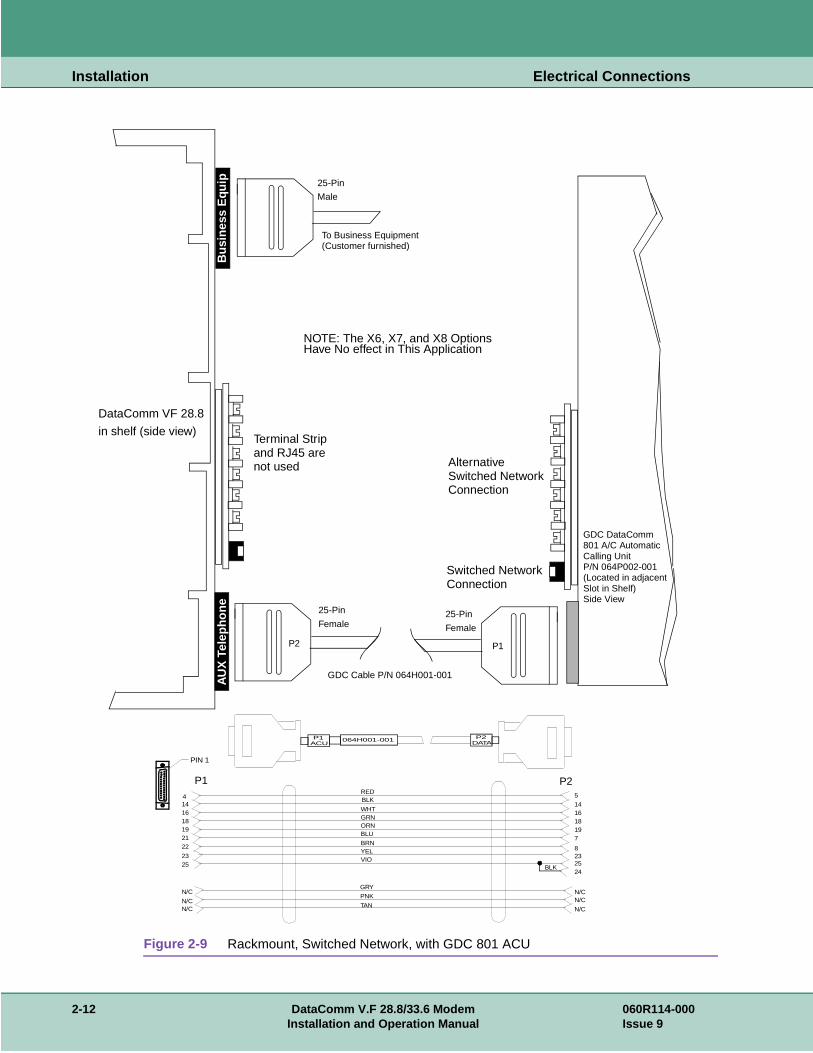
Figure 2-9 Rackmount, Switched Network, with GDC 801 ACU
���������������������������������������������������������������������������������������������������������������������������������������������������������������������������������������������������������������������������������������������������������������������������������������������������������������������������������������������������������������������������������������������������������������������������������������������������������������������������������������������������������������������������������������������������������������������������������������������������������������������������������������������������������������������������������������������������������������������������������������������������������������������������������������������������������������������������������������������������������������������������������������������������������������������������������������������������������������������������������������������������������������������������������������������������������������������������������������������������������������������������������������������������������������������������������������������������������������������������������������������������������������������������������������������������������������������������������������������������������������������������������������������������������������������������������������������������������������������������������������������������������������������������������������������������������������������������������������������������������������������������������������������������������������������������������������������������������������������������������������������������������������������������������������������������������������������������
Bus
ines
s E
quip
To Business Equipment
DataComm VF 28.8
in shelf (side view)
AU
X T
elep
hone
J2
Terminal Stripand RJ45 arenot used
25-Pin
Male
25-Pin
Female
(Customer furnished)
AlternativeSwitched NetworkConnection
Switched NetworkConnection
P2 P1
GDC Cable P/N 064H001-001
GDC DataComm801 A/C AutomaticCalling UnitP/N 064P002-001(Located in adjacentSlot in Shelf)Side View
NOTE: The X6, X7, and X8 OptionsHave No effect in This Application
25-Pin
Female
REDBLK
WHTGRNORNBLU
BRNYELVIO
5141618197
8232524
N/CN/C
N/C
4141618192122
2325
N/C
N/CN/C
P1 P2
GRY
PNK
TAN
PIN 1
P2DATA
P1ACU
064H001-001
BLK
2-12 DataComm V.F 28.8/33.6 Modem 060R114-000Installation and Operation Manual Issue 9

Installation Electrical Connections
Table 2-2 Auxiliary Telephone Connector Pinout
Pin No.* Designation Function
4 LG Return (ground)
5 TD Talk/data indication from the 801 ACU
6 M I Mode indicator (uses pin 25 as MIC)
7 T (tip) 2-wire transmit tip (switched network)
8 R (ring) 2-wire transmit ring (switched network)
11 MIC Mode indicator common (ground)
13 M I Mode indicator
14 C Provides ground for the 801 ACU
16 D1 ACU contact closure to ground, which forces modem to transfer to data mode
18 PR Programming resistor sense
19 PC Programming resistor common (ground)
21 T (tip) Phone tip
22 R (ring) Phone ring
25 TGD Return (ground) (used as MIC with pin 6)
*Pins 1, 2, 3, 9, 10, 12, 15, 17, 20, 23 and 24 are not used.
Table 2-3 50-Pin VF Connector Pinout
50-Pin ConnectorPrivate Line (Option X6)
Switched Network (Option X7)
Auto Dial Restoral (Option X8)
Line
26 T T T SN 1/9
1 R R R SN
27 T1 PC T1 PL
2 R1 PR R1 PL
28 not used MI R PL
3 not used MIC T PL
29 T T T SN 2/10
4 R R R SN
30 T1 PC T1 PL
5 R1 PR R1 PL
31 not used MI R PL
6 not used MIC T PL
32 T T T SN 3/11
7 R R R SN
33 T1 PC T1 PL
8 R1 PR R1 PL
34 not used MI R PL
(Sheet 1 of 2)
060R114-000 DataComm V.F 28.8/33.6 Modem 2-13Issue 9 Installation and Operation Manual

Installation Electrical Connections
9 not used MIC T PL 3/11
35 T T T SN 4/12
10 R R R SN
36 T1 PC T1 PL
11 R1 PR R1 PL
37 not used MI R PL
12 not used MIC T PL
38 T T T SN 5/13
13 R R R SN
39 T1 PC T1 PL
14 R1 PR R1 PL
40 not used MI R PL
15 not used MIC T PL
41 T T T SN 6/14
16 R R R SN
42 T1 PC T1 PL
17 R1 PR R1 PL
43 not used MI R PL
18 not used MIC T PL
44 T T T SN 7/15
19 R R R SN
45 T1 PC T1 PL
20 R1 PR R1 PL
46 not used MI R PL
21 not used MIC T PL
47 T T T SN 8/16
22 R R R SN
48 T1 PC T1 PL
23 R1 PR R1 PL
49 not used MI R PL
24 not used MIC T PL
50 UNASSIGNED UNASSIGNED UNASSIGNED -
25 UNASSIGNED UNASSIGNED UNASSIGNED
Table 2-3 50-Pin VF Connector Pinout (Continued)
50-Pin ConnectorPrivate Line (Option X6)
Switched Network (Option X7)
Auto Dial Restoral (Option X8)
Line
(Sheet 2 of 2)
2-14 DataComm V.F 28.8/33.6 Modem 060R114-000Installation and Operation Manual Issue 9

Installation Special Considerations for High Data Rates
cable se of ngth, nce.
tor-to- cable's -C
of data
r less. eet) by
DTE Cables
With the TIA/EIA-232-F (ITU-T V.24/V.28/ISO 2110) DTE interface, use standard TIA/EIA-232-F cables (except as noted under Special Considerations for High Data Rates).
With the V.35 (ITU-T V.24/V.28/V.35/ISO 2593) DTE interface, use GDC adapter cable P/N 027H572-001.
With the EIA/TIA-530-A (ITU-T V.10/V.11/V.24/ISO 2110 Amendment 1) DTE interface, useGDC cable P/N 027H525-XXX.
Special Considerations for High Data Rates
Because of the high data rates possible with the V.F 28.8/33.6, the type and length of the DTEare important factors in ensuring data integrity. The modem's higher data rates require the ushielded DTE cables. Further, the cable's capacitance and resistance, which vary with its lemust be evaluated to ensure that it can support the chosen data rate over the required dista
Cable capacitance is specified in two categories: conductor-to-conductor (C-C) and conducshield (C-S). Each of those capacitance values is expressed in PicoFarads per foot (pF/ft). Atotal capacitance is arrived at by adding C-C to C-S and multiplying by its length in feet. Thefollowing example illustrates calculations for the total capacitance of a 10-foot cable with a Ccapacitance of 12.5 pF/ft and a C-S capacitance of 22.0 pF/ft:
Total capacitance = [(C-C) + (C-S)] * 10
Total capacitance = (12.5 + 22.0) * 10
Total capacitance = 34.5 * 10
Total capacitance = 345 pF
The following table shows the greatest total capacitance that can be tolerated for each rangerates.
A DTE cable for use with the V.F 28.8/33.6 modem must have total resistance of 20 ohms oTo calculate a cable's resistance, multiply its specified resistance value (in ohms per 1000 fits length (in feet). The following example illustrates the calculation for a 10-foot cable with aresistance of 24 ohms/1000 ft:
Total Resistance = (24/1000) * 10
Total Resistance = 0.024 * 10
Total Resistance = 0.24 ohms
DATA RATE (kbps) Total Capacitance (pF)
0.0 - 20.0 2400
20.0 - 30.0 1200
30.0 - 60.0 900
60.0 - 100.0 450
100-0 - 128.0 200
060R114-000 DataComm V.F 28.8/33.6 Modem 2-15Issue 9 Installation and Operation Manual

Installation Verifying Your Connections
t
e
cable -T
25), lower
steps
el is
ected
all
puter tion.
pond your r a A.
The following table shows for two GDC DTE cables the greatest lengths that can be used adiffering data rates. The two cables shown are 028H511-XXX (DB25 male-to-female) and 028H502-XXX (DB25 male-to-male). When ordering these cables, replace the -XXX with ththree-digit dash number that indicates the desired length (50, 25, 10, or 5 feet).
Because of the high data rates possible with the V.F 28.8/33.6, the type and length of the DTEare an important factor in ensuring data integrity. When using the built-in TIA/EIA-232-F (ITUV.24/V.28/ISO 2110) DTE interface, use GDC cable P/N 028H511-XXX (male-to-female DBno longer than five feet at the highest DTE rate (128 kbps). Longer lengths are available forDTE rates or when using the optional EIA/TIA-530-A (ITU-T V.10/V.11/V.24/ISO 2110 Amendment 1 DTE interface card.
Verifying Your ConnectionsYour modem should now be connected. You can verify all your connections by following the listed below.
1. To verify that the power supply is connected properly, see if the display on the front panflashing decimal point four (refer to Chapter 3 for front panel operation). If not, reset the modem. If decimal point four still does not flash, then either the power supply is not connproperly, or the modem is not functioning.
2. To verify that the switched network telephone line is connected properly, place a voice cusing a telephone plugged into the modem.
3. If you are using a terminal as your DTE, proceed to the next step. If you are using a comas your DTE, then run your communications software and configure it for terminal emulaIf you are using an intelligent communications software package, it may be necessary toconfigure it for "interactive" mode. See Chapter 4 for further details.
4. Type the command AT followed by a carriage return on the DTE: the modem should reswith an OK message. If the modem does not respond with an OK message, then either DTE interface cable is not connected properly or your DTE is not configured properly. Focomplete list of compatible DTE configurations such as speed and parity, see Appendix
DATA RATE (kbps)
028H511- 028H502
-050 -025 -010 -005 -050 -025 -010 -005
0.0 - 20.0 X X
20.0 - 30.0 X X
30.0 - 60.0 X X
60.0 - 100.0 X X
100.0 - 128.0 X X
2-16 DataComm V.F 28.8/33.6 Modem 060R114-000Installation and Operation Manual Issue 9
ntrol
us
's call uses set
's
e esting
Chapter 3: Operation
OverviewThis Chapter describes how to operate and configure the V.F 28.8/33.6 modem. Modem cofunctions can be performed in three ways:
• by means of the modem's front panel switches and display;
• by means of AT commands sent to the modem from a terminal, PC, or other asynchronoDTE;
• by means of ITU-T V.25 bis commands sent to the modem from a terminal, PC, or other asynchronous DTE;
This chapter begins by describing the use of the front panel. That is followed by the modemcontrol functions, which are carried out principally by means of AT commands. The broaderof the AT command set for configuration and control are then described. The AT command provides a broader range of capabilities than does the front panel.
Chapter 4 describes each AT command in detail, which involves also describing the modemconfigurable characteristics and functions that are controlled by the commands.
Chapter 5 describes the V.25 bis command set.
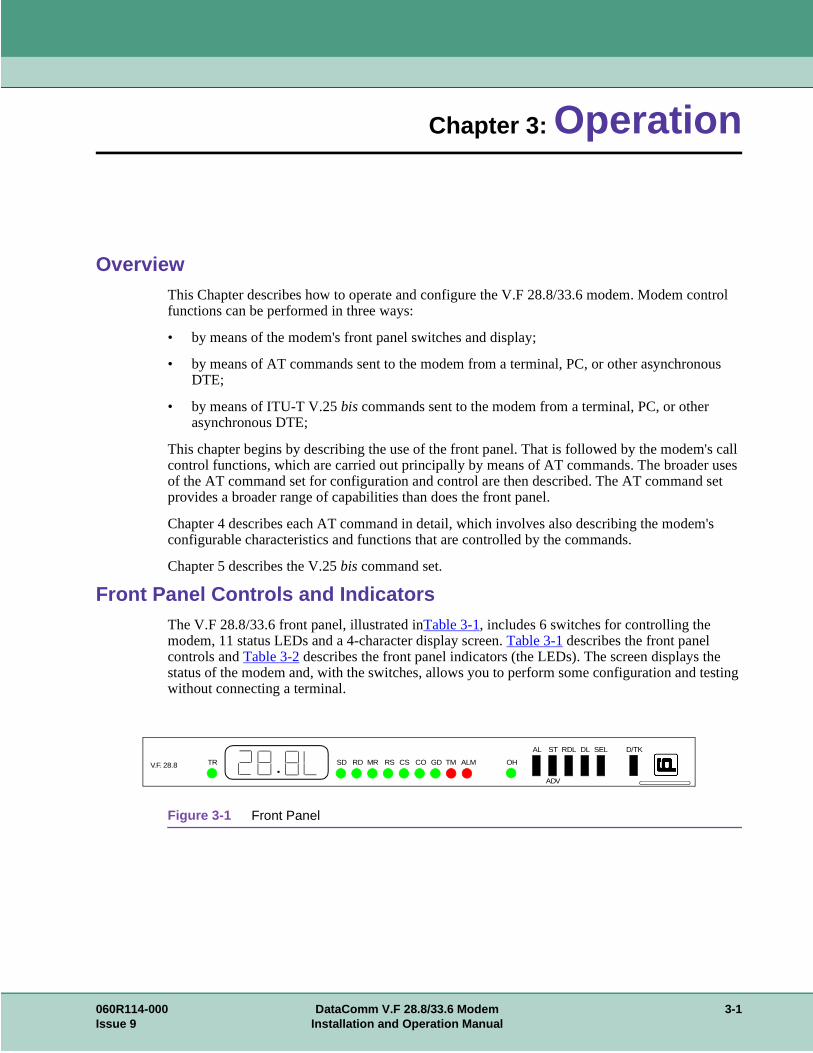
Front Panel Controls and IndicatorsThe V.F 28.8/33.6 front panel, illustrated inTable 3-1, includes 6 switches for controlling the modem, 11 status LEDs and a 4-character display screen. Table 3-1 describes the front panel controls and Table 3-2 describes the front panel indicators (the LEDs). The screen displays thstatus of the modem and, with the switches, allows you to perform some configuration and twithout connecting a terminal.
Figure 3-1 Front Panel
V.F. 28.8 TR SD RD MR RS CS CO GD TM ALM OH
AL ST RDL DL SEL D/TK
ADV
060R114-000 DataComm V.F 28.8/33.6 Modem 3-1Issue 9 Installation and Operation Manual

Operation Front Panel Controls and Indicators
Table 3-1 Front Panel Controls
Key Function
AL Starts/stops CCITT V.54 Loop 3 (Local Loop or ANALOOP).Can be used before ST for CCITT V.54 Loop 3 with Self-Test (Local Loop Self-Test or ANALOOP Self-Test).
ST Starts End-to-End Self-Test. (Use AL, RDL or DL to stop the test.)Can be used after AL for CCITT V.54 Loop 3 with Self-Test.Can be used after RDL for CCITT V.54 Loop 2 with Self-Test.
ADV Advances the display to the next configuration selection.Profiles include:
FAC0 to FAC3: Factory (fixed) profile 0 to factory profile 3.USr0 to USr3: User profile 0 to user profile 3.
Command sets include:At-C Enable the AT command set.OFFC Disable all command sets.25AC Enable the V.25 bis asynchronous command set. (Future use)25bC Enable the Binary Synchronous Communications (BSC or BISYNC)
command set. (Future use)25HC Enable the V.25 bis HDLC synchronous command set. (Future use)
RDL Starts/stops CCITT V.54 Loop 2 (Remote Digital Loopback).Can be used before ST for CCITT V.54 Loop 2 with Self-Test (Remote Digital Loopback Self-Test).
DL Starts/stops CCITT V.54 Loop 2 (Digital Loopback).
SEL In configuration mode: Selects the displayed profile as the new configuration.In idle mode: Displays DTE speed for two seconds.In data mode: Displays DCE speed for two seconds.
D/TK Switch between data mode and talk mode.
3-2 DataComm V.F 28.8/33.6 Modem 060R114-000Installation and Operation Manual Issue 9

Operation Front Panel Controls and Indicators
Table 3-2 Front Panel Indicators
LED DefinitionLED State
Description
TR Data Terminal Ready On The DTE has turned On DTE interface pin 20 (or DTR is On), indicating it is ready for data communications.
Off The DTE has turned Off pin 20, indicating it is not ready for data communications.
SD Send Data On Indicates a SPACE condition in the transmitted data.
(Transmitted Data) Off Indicates a MARK condition.
RD Received Data On Indicates a SPACE condition in the received data.
Off Indicates a MARK condition.
MR Modem Ready On The DCE has turned On DTE interface pin 6 (or DSR is On), indicating it is ready for data communications.
Off The DCE has turned Off pin 6, indicating it is not ready for data communications.
Flashing The modems are handshaking.
RS Request to Send On The DTE has turned On DTE interface pin 4 (or RTS is On), indicating that the DTE is requesting the modem for data transmission.
Off Pin 4 is Off.
CS Clear to Send On The modem has turned On DTE interface pin 5 (or CTS is On), indicating it is ready to transmit data.
Off The modem has turned Off pin 5, indicating it is not ready to transmit data.
CO Carrier On(Data Carrier Detect)
On The modem has turned On DTE interface pin 8 (or DCD is On), indicating it is receiving data.
Off The modem has turned Off pin 8, indicating it is not receiving data.
GD Good Data On The modem is receiving an acceptable carrier level and is equalized.
Off The modem is not receiving an acceptable carrier level or is not equalized.
TM Test Mode On The modem is in a test mode.
Off The modem is not in a test mode.
ALM Alarm Not used.
OH Off-Hook On The modem is in the off-hook state.
Off The modem is in the on-hook state.
060R114-000 DataComm V.F 28.8/33.6 Modem 3-3Issue 9 Installation and Operation Manual

Operation Operating Procedures
lays rm
eed for
the
Operating ProceduresThe V.F 28.8/33.6 allows you to perform a number of operations from the front panel. It dispstatus information and allows you to configure some aspects of the modem, as well as perfodiagnostics.
Status
If the DCE speed changes while the modem is in data mode, the modem displays the new sptwo seconds.
Note The screen illustrations below are for a modem mounted in a DataComm Enclosure. Whenmodem is rackmounted, the screen is turned on end.
DataComm Encl. Rackmount
While the modem is in data mode or idle mode, it flashes decimal point four (on the right side of the screen) to indicate power on.
While the modem is in idle mode, press SEL to display the DTE (terminal) speed for two seconds. The example illustrates the display for the last AT connect speed (the t on top indicates that the modem is displaying the terminal speed).
While the modem is in data mode, press SEL to display the DCE speed (the line or VF speed) for two seconds. The example illustrates the display for 28.8 kbps (the L on top indicates that the modem is displaying the line speed).
3-4 DataComm V.F 28.8/33.6 Modem 060R114-000Installation and Operation Manual Issue 9

Operation Operating Procedures
25bC
splays
m is
Configuration
The V.F 28.8/33.6 allows you to select a configuration profile and a command set.
To scroll through the profile and command set selections, press ADV. Profiles include FAC0through FAC3 and USr0 through USr3. Command sets include At-C and OFFC, and 25AC, and 25HC (for future use). Refer to Table 3-1 for details.
To abort configuration mode press AL, RDL or DL.
To select and make active the displayed profile or command set, press SEL. The modem dithe new configuration.
Diagnostics
End-to-End Self-Test
To enter configuration mode press SEL, then press ADV (within two seconds). The modem displays the last profile selected from front panel. The example illustrates the display for factory (fixed) profile 0.
Note You can enter configuration mode and select a profile or command set only while the modeidle.
The V.F 28.8/33.6 allows you to perform the diagnostics described below. If you attempt to start a test which cannot be run (e.g., End-to-End Self-Test when the local modem is not connected to another modem), the modem displays nA (not applicable).
To start the test, press ST. The modem flashes the TM LED and displays the test name while it is setting up the test, then lights the TM LED and displays four digits of the error count (0000 to 9999). It indicates larger numbers by lighting decimal point one and displaying the four least significant digits of the actual count (for example, the actual error count is 12345, but the modem displays 2.345). To stop the test, press AL, RDL or DL.
Setup
Running
060R114-000 DataComm V.F 28.8/33.6 Modem 3-5Issue 9 Installation and Operation Manual

Operation Operating Procedures
CCITT V.54 Loop 3 Local Loop)
CCITT V.54 Loop 3 with Self-Test (Local Loop Self-Test)
CCITT V.54 Loop 2 (Remote Digital Loopback)
To start the test, press AL. The modem flashes the TM LED and displays the test name while it is setting up the test, then lights the TM LED and lights decimal point three while the test is running. To stop the test, press AL, RDL or DL.
Setup
Running
To start the test, press AL then press ST. The modem flashes the TM LED and displays the test names while it is setting up the test, then lights the TM LED and displays four digits of the error count (0000 to 9999). It indicates larger numbers by lighting decimal point one and displaying the four least significant digits of the actual count (for example, the actual error count is 12345, but the modem displays 2.345). To stop the test, press AL, RDL, or DL.
Setup AL
Setup ST
Running
To start the test, press RDL. The modem flashes the TM LED and displays the test name while it is setting up the test, then lights the TM LED and lights decimal point two while the test is running. To stop the test, press AL, RDL or DL. If the remote modem initiated the test, the local modem lights decimal points three and four while the test is running.
Setup
Running (Local)
Running Remote
3-6 DataComm V.F 28.8/33.6 Modem 060R114-000Installation and Operation Manual Issue 9

Operation Operating Procedures
ng a
vided
wing
CCITT V.54 Loop 2 with Self-Test (Remote Digital Loopback Self-Test)
CCITT V.54 Loop 2 (Digital Loopback)
Call Control
Call control involves call initiation, completing a connection, call answering, and disconnecticall.
The V.F 28.8/33.6 modem can be made to initiate a call in any of three ways:
• Manually, using a telephone number supplied at the time the call is initiated
• Manually, using a telephone number stored previously in one of the 10 memory cells profor that purpose
• Automatically in response to an Off-to-On transition of the DTR interface circuit, using atelephone number stored previously in memory cell 0
The following three headings describe the procedures required for each type of call initiation.Table 3-3 describes common commands used for call initiation, answering, and disconnection.
Call completion, answering, and disconnection are discussed under their own headings follothe table.
To start the test press RDL, then press ST. The modem flashes the TM LED and displays the test names while it is setting up the test, then lights the TM LED and displays four digits of the error count. It indicates larger numbers by lighting decimal point one and displaying the four least significant digits of the actual count (for example, the actual error count is 12345, but the modem displays 2.345). To stop the test, press AL, RDL or DL.
Setup RDL
Setup ST
Running
To start the test, press DL. The modem flashes the TM LED and displays the test name while it is setting up the test, then lights the TM LED and lights decimal point one while the test is running. To stop the test, press AL, RDL or DL.
Setup
Running
060R114-000 DataComm V.F 28.8/33.6 Modem 3-7Issue 9 Installation and Operation Manual

Operation Operating Procedures
the
Table 3-3 Common Call Control Commands
Manual Call Initiation
The following example illustrates manual call initiation with a telephone number supplied at time of the call. At the terminal or computer keyboard, type
AT DP 9W (809) 555-1234 (enter)
where:
Command This will..... Remember.....
AT get the modem's attention, telling it that a command is to follow.
this command must always precede any command line, except A/.
AT D get the modem to dial the specified telephone number that follows.
your number can contain up to 30 digits
P(following D command)
tell the modem to pulse dial. you can use dial digits 0 through 9 for pulse dialing.
T(following D command
tell the modem to tone dial. you can use dial digits 0-9 and symbols A, B, C, D, #, * for tone dialing.
W(as part of dial command)
indicate to the modem that it must wait for a dial tone before dialing the number that follows.
you will use this command when you have to dial 9 to obtain an outside line.
;(as part of dial command)
cause the modem to return to the command mode after it has dialed the number, rather than immediately entering data mode.
this will serve to separate a command string containing more than 30 characters (so as not to overflow the buffer).
Sn(following D command
instructs the modem to dial a previously stored number.
you can store 10 telephone numbers (n = 0 - 9) up to 30 digits each.
R(as last character in dial command
cause the modem to establish a call in answer mode when calling an originate-only modem.
the R command must be the last character in the dial string before you enter a carriage return.
AT A force the modem to answer incoming call.
the modem will not wait for a ring; no matter what is specified in the S0 register (see S-Registers in Chapter 4). This command is used for manually answering a call.
AT H force the modem to hang up. if you are in data mode, you must first enter command mode before using this command.
AT AT command prefix, instructs modem to pay attention to the characters that follow
D dial command, instructs modem to dial
P dial modifier, instructs modem to use pulse dialing
9 instructs modem to dial 9 (to reach an outside line)
W dial modifier, instructs modem to wait for a dial tone before continuing
(809) 555-1234 number modem is to dial - it will ignore parentheses, spaces, and hyphens
(enter) pressing Enter or Return key sends command line to the modem
3-8 DataComm V.F 28.8/33.6 Modem 060R114-000Installation and Operation Manual Issue 9

Operation Operating Procedures
all
mory
pe
all
umber t panel.
nswer of the er the
front
rminal ition 0.
The description of the Dial (Dn) command that appears in Chapter 4 includes the functions of dial modifier characters (such as P and W in this example).
The following examples illustrate how to store a telephone number in one of the modem's mecells and how to initiate a manual call using a stored number.
To store a telephone number type
AT &Z3=(809) 555-1234 (enter)
where:
When you require a modem connection to that stored telephone number at any later time, ty
AT DT S3 (enter)
where:
The description of the Dial (Dn) command that appears in Chapter 4 includes the functions of dial modifier characters (such as T and S in this example).
Manual Calling Using a Telephone Set
Manual calling can be done from a telephone set connected to the modem: Simply dial the nof the modem or data service you wish to connect to, and then press the D/TK key on the fron
If you wish to talk before connecting the modem, the answering modem should disable auto-aby setting S0=0. After the conversation, the originate modem should be engaged by meansD/TK key on its front panel, and the answering modem should be engaged by means of eithAT command A or its D/TK key.
To place calls manually using a telephone set:
1. Plug a telephone into the PHONE jack of the modem.
2. Dial the number of the modem or data service you wish to connect to.
3. When you hear the remote modem answertone, immediately press the D/TK key on thepanel. This will force the modem to go off hook and begin the handshaking process.
Automatic Call Initiation in Response to DTR
The AT commands %Z1 and %Z3 both instruct the modem to observe the state of the Data TeReady (DTR) interface lead, and to perform automatic call initiation when an Off-to-On transoccurs on that lead. This function always uses the telephone number stored in memory cell
AT AT command prefix, instructs modem to pay attention to the characters that follow
&Z3=(809) 555-1234 instructs modem to store the telephone number in non-volatile memory cell 3
(enter) pressing Enter or Return key sends command line to the modem
AT AT command prefix, instructs modem to pay attention to the characters that follow
D dial command, instructs modem to dial
T dial modifier, instructs modem to use tone dialing
S3 dial modifier, instructs modem to dial number stored in memory cell 3
(enter) pressing Enter or Return key sends command line to the modem
060R114-000 DataComm V.F 28.8/33.6 Modem 3-9Issue 9 Installation and Operation Manual

Operation Operating Procedures
DTR
ote e the
ard and mand.
from
e r will
matic
nt ring equals re.
f ter 4.
voice auto-
s the the
When %Z1 is used, the modem will dial automatically only when it detects a transition on thelead.
When %Z3 is used, the modem will dial automatically whenever it is not connected to a remmodem and the DTR lead is On. The significance of this is that the %Z3 command will causmodem to perform automatic re-dial for recovery of a broken connection without requiring intervention by the DTE
Completing a Connection
After you issue a dial command, a CONNECT result code will appear if the connection is successful,. It means you are connected to the remote end. See Chapter 4 for a list of standextended result codes. The result codes appear on your DTE screen when you issue a com
Usually you will need to press Enter or Return on the keyboard in order to receive a promptthe answering equipment. If you do not do so, you may be disconnected.
The CS and CO indicators will remain on while the V.F 28.8/33.6 modem is connected to thremote end. The SD indicator will flash while the modem is sending data and the RD indicatoflash while it is receiving data from the remote end.
Call Answering - Automatic
The V.F 28.8/33.6 modem automatically answers and switches to the data mode if the autoan-swering function is enabled. The modem has built-in "ring-detection" circuitry that can beenabled to provide automatic response to incoming calls. The value stored in S-Register 0 determines whether auto-answer is enabled. If the value is greater than 0, the modem will cousignals on the line and display a RING message for each ring it counts. Once the ring countor exceeds the value of S0, the modem will go off hook and begin the handshaking procedu
The default value of the S0 register is n = 1 (auto-answer enabled on the first ring). The value on is programmable in AT modes of operation. For AT operation, refer to S-Register 0 in Chap
Call Answering - Manual
You may prefer that the modem not answer incoming calls automatically; for example, if both and data calls will be received on the same line. Storing the value 0 in S-Register 0 disablesanswer so the modem will not answer calls by itself under any circumstances.
To implement manual answering, follow these steps:
1. Plug a telephone into the PHONE jack of your modem.
2. When the phone rings, answer it manually.
3. If the incoming call is a data call, you can either enter the command ATA (enter), or presD/TK key on the front panel. Either action will cause the modem to go off-hook and beginhandshaking sequence.
Note For more information on the S-Registers, see Chapter 4.
3-10 DataComm V.F 28.8/33.6 Modem 060R114-000Installation and Operation Manual Issue 9

Operation Automatic Calling Unit (ACU) Support
syn- string, e the
R) an be
odem
for 1 e
y nect
or any eceive nuous s and
U, ,
ations to the st first
Disconnecting a Call
There are several ways to disconnect a call:
• H command - disconnects the modem from the VF line. When using the modem in the achronous mode, first type the ESCAPE sequence (ESCAPE is a programmable characterdefault +++). When the modem returns an OK to the DTE, type AT H (enter) to terminatconnection.
• Loss of DTR - an irreversible data mode disconnect sequence occurs if circuit 108.2 (DTturns Off for more than 50 milliseconds when the modem is in data mode. The modem coptioned for circuit 108.2 forced On (terminal dial mode) so that a DTE cannot cause a disconnect to occur using circuit 108.2.
• Character abort - when this feature is enabled, any character sent from the DTE to the mat the originate end during dialing or the handshake sequence will abort the call. %Kn controls this function in all command modes.
• Loss of carrier - the modem will go on-hook if the handshake sequence is not completedsuccessfully within the time specified in S-Register 7. This abort timer is programmable to 30 seconds via the S7=x command. The originating and answering modem both have thabort timer active during the handshake sequence.
• No answer or busy - when an originating call is not answered within the time specified bS-Register 7, the modem will disconnect. If it detects a busy tone, the modem will disconimmediately and display the BUSY message.
• Long space disconnect - if optioned to do so via the Yn command, the V.F 28.8/33.6 will initiate and respond to the long space disconnect procedure. When initiating disconnect (freason except loss of carrier) the modem will transmit 4 seconds of continuous spacing (rdata clamped to a mark), and then go on-hook. A modem receiving 1.6 seconds of contispace on the VF line will go on-hook. This feature is only functional at speeds of 2400 bplower.
Automatic Calling Unit (ACU) Support
You may use a DataComm 801A/C ACU with the V.F 28.8/33.6 modem. To connect the ACrefer to Figure 2-9 in Chapter 2. For detailed installation and operating procedures for the ACUrefer to GDC Publication No. 064R101.
MI/MIC Operation
This feature allows a 503/2503-type telephone to function as a talk/data switch in such applicas modem pooling, security callback, and PBX operations. Connect the modem and phone phone line using a telephone company USOC data jack. To use the MI/MIC feature, you muenable it with the %M1 command.
To place a call:
1. Lift the handset, then the exclusion key.
2. Listen for dial tone, then dial the desired number.
060R114-000 DataComm V.F 28.8/33.6 Modem 3-11Issue 9 Installation and Operation Manual

Operation SteadFast Security Password
et back rson for
m the
dshake ems in onal
, the quired.
g the dem). uses ll. The means
cell 1,
ew call, dial ulted in
datory ans of , the te the one
e
3. If a modem answers the call, it sends a tone. When you hear this tone, place the handsin its cradle. The modems will attempt to handshake and enter data mode. (If another peanswers the call, instruct that person to manually switch the modem to data mode, listenthe tone, then place the handset back in its cradle.)
To terminate the call:
1. Lift the handset, then the exclusion key.
2. Place the handset back in its cradle within 0.75 seconds. The modems will disconnect frophone line.
SteadFast Security Password
In SteadFast Security the modem that initiates the call sends the password as part of its hansequence. In order to use a SteadFast Security password, both modems must be GDC modoptioned for SteadFast Security (%S1). Both modems must have the same password savedpassword memory cell 0 (%P0 = XXX). The remote user does not have to type in any additipasswords.
When only the SteadFast Security password is enabled, and pass-thru operation is selectedpassword procedure is completed during the handshake and no further user intervention is re
A remote user initiating a call can invoke the SteadFast Security callback feature by includinST dial command modifier \n (where n represents a phone number cell in the answering moThe dial command modifier, when combined with the valid SteadFast Security password, cathe modem to disconnect the incoming cal and dial the number from the specified memory cecallback phone number must be saved in a phone number cell of the answering modem by of the &Zn=nnn command. Up to 10 phone numbers can be stored in cells 0-9 using the &Zcommand.
For example, to call a modem at 555-1212 and have it call back the phone number stored inenter:
ADT5551212\1
After handshaking and a short delay, the remote modem terminates the call, and places a nusing the phone number stored in cell 1, back to the modem that initiated the process. If thecommand modifier had not been included, the SteadFast Security password would have resa pass-thru connection.
The central site, or answering, modem can be configured (using the%S4 command) for mancallback with SteadFast Security password. In this arrangement the calling modem must beoptioned for%S1. A callback phone number must be saved in the answering modem by methe &Zn=nnn command. When using SteadFast Security password with mandatory callbackcaller must include a valid callback cell number with the phone number that is dialed to initiaconnection (Example ATD5551212\1). If the callback cell number is not supplied with the phnumber, the answering modem will disconnect the call.
Note a. To switch back to talk mode, first lift the handset, then the exclusion key.
b. When you are not using the MI/MIC feature or do not intend to use it, disable it with th%M0 command to avoid cable noise problems.
3-12 DataComm V.F 28.8/33.6 Modem 060R114-000Installation and Operation Manual Issue 9

Operation SteadFast Security Password
odem y cells n be
not be cells in
d, the
ption, ans of ns of
llback ack to ll, you
ll for call
ify the
o an on-
phone ects the which ith the
(&H1),
r to
to
On-Line Password Security
On-Line Password Security with pass-thru requires that the answering modem be a GDC moptioned for on-line password security using the%S0 command. The modem has ten memorfor storing passwords. The command for storing a password is %Pn=xxx, where n is the passwordcell number and xxx is the password. The memory cell can be any digit, 0-9. The password caany string of up to ten alphanumeric and punctuation characters (exception: comma “,” may used). The modem compares received on-line passwords to the contents of all ten memory search of a match.
When the remote caller initiates a call to a modem that as on-line password security enablemodems handshake then the caller receives the prompt.
ENTER PASSWORD
The operator has 15 seconds to respond with a valid password.
If the remote user initiating the call wants to use the callback with online password security oa callback phone number must have previously been saved in the answering modem by methe &Zn=nnn command. Up to 10 phone numbers can be stored in cells 0 through 9 by meathe &Z command. You can view the stored phone numbers by using the &V command.
Callback with online password also requires that an online password be configured with a caextension. A callback extension causes the answering modem to disconnect and then call bthe modem that placed the original call. When you configure an on-line password memory cemust enable or disable its callback extension capability with the %Fn=x command. In this command, n is the online password cell number and x defines if and how the password in that cecan be used for callback. (Use a phone number that is stored in cell # to call back, ask user back phone number, or not allow any callback.)
The comma, which cannot be used as a password, functions as a special character to identcallback request extensions.
There are two callback request extensions that a remote operator may be permitted to add tline password: R or C. A password stored with password cell qualifier %Fn=0 will not accept any callback extension attached.
The roving callback extension (,R) causes the answering modem to prompt the caller for a telenumber to use for the callback. Once the number is supplied, the answering modem disconnoriginal call and places a return call using the number it has just been given. The password tothe roving callback extension is attached must have been stored in the answering modem wappropriate password cell qualifier, %Fn=1 or %Fn=3.
Note To use SteadFast Security password, the handshake modes of the modems must be V.34 V.32 bis (&H3) or V.32 (&H5).
Telephone numbers stored for security callback should always include the :n (retry) modifiecompensate for any delay in receiving the dial tone from the Central Office after the initial connection is terminated. Configure the modem to make at least three additional attempts dial the number.
060R114-000 DataComm V.F 28.8/33.6 Modem 3-13Issue 9 Installation and Operation Manual
Operation SteadFast Security Password
for the er is the ell
call to quence
hen the
a mode
a mode
The memory cell callback extension (,C) causes the answering modem to prompt the caller number (0-9) of a phone number memory cell in the answering modem. Once the cell numbsupplied, the answering modem disconnects the original call and places a return call using telephone number stored in the specified memory cell. the password to which the memory ccallback extension is attached must be stored in the answering modem with the appropriatepassword cell qualifier, %Fn=2 or %Fn=3.
The following two examples illustrate what the remote caller sees on screen when placing aa modem that has on-line password security enabled and requesting a call back. First, the seof events when using a callback number stored in a memory cell. The modems handshake, tcallers screen displays the prompt:
ENTER PASSWORD
Within 15 seconds the caller has to respond with:
password,C<ENTER> using a valid password configured in the answering modem
The caller’s screen displays the prompt:
ENTER CELL NUMBER
the caller has to respond with:
cell #<ENTER> specifying the number of the memory cell in the answering modem that is configured with the calling modem’s number
The caller’s screen displays:
NO CARRIER - to indicate the disconnect
RING - to indicate the incoming cal
CONNECT - followed by the appropriate connect message, indicating the modems are in dat
The next example illustrates the sequence of events when using a roving callback number.
The modems handshake, then the caller’s screen displays the prompt:
ENTER PASSWORD
Within 15 seconds the caller has to respond with:
password,R<ENTER> using a valid password configured in the answering modem
The caller’s screen displays the prompt:
ENTER PHONE NUMBER
The caller has to respond with:
nnnnnnnnnn<ENTER> specifying the number that the answering modem needs to dial to establish the callback
The caller’s screen displays:
NO CARRIER - to indicate the disconnect
RING - to indicate the incoming cal
CONNECT - followed by the appropriate connect message, indicating the modems are in dat
3-14 DataComm V.F 28.8/33.6 Modem 060R114-000Installation and Operation Manual Issue 9

Operation SteadFast Security Password
adFast ecurity online
ack
If both the SteadFast Security password and online password security are enabled, the SteSecurity procedure takes place first, during the handshake sequence. After the SteadFast Spassword has been confirmed the caller is prompted first for the online password, then for thecallback cell number or the phone number for a roving callback.
Table 3-4 details the combinations of available password and callback features, and the configuration they require.
Note When both SteadFast Security and online password security are enabled, only online callbcan take place. SteadFast Security callback is blocked when online password security is enabled.
Table 3-4 GDC V.34 Modem Password/Callback Security
Security Feature Originate Modem Configuration Answer Modem Configuration
Passwords disable %SATDT (phone number)
%S0
SteadFast Security (Pass-thru)
%S1%P0=(SF password)ATDT (phone number)
%S1%P0=(SF password)
Online Password (Pass-thru) %S0ATDT (phone number)
%S2%P1=(O/L password)%F1=0
Online Password & SteadFast Security - no callback
%S1%P0=(SF password)ATDT (phone number)
%S3%P0=(SF password)%P1=(O/L password)
SteadFast Security - callback w/number in Cell #1
%S1%P0=(SF password)ATDT (phone number)
%S1%P0=(SF password)&Z1=(C/B phone number)
Online Password - callback w/password in Cell 1(,C) (Not mandatory)
%S0ATDT (phone number)
%S2%P1=(O/L password)%F1=2&Z1=(C/B phone number)
Online Password & SteadFast Security - callback w/Password in Cell 1 (,C) (not mandatory)
%S1%P0=(SF password)ATDT (phone number)
%S3%P0=(SF password)%F1=2&Z1=(C/B phone number)
SteadFast Security w/mandatory callback w/number in Cell #1
%S1%P0=(SF password)ATDT (phone number)\1
%S4%P0=(SF password)&Z1=(C/B phone number)
Notes: Factory default command &F does not affect the %P, %F, or &Z commands.Use of SteadFast Security requires that both modems be GDC V.34 modems configured to handshake at V.34, V.32 bis, or V.32.Use of online passwords requires that the answer modem be a GDC V.34 modem.Passwords can be any string of up to ten alphanumeric and punctuation characters (except a comma “,”).The SF (SteadFasT) password used during the handshake sequence is stored in the %P0 memory cell and must be the same on both modems.O/L (online) passwords are stored in memory cells %P0 through %P9.Callback numbers for SteadFast Security and on-line password security can be stored in memory cells &Z0 through &Z9.
(Sheet 1 of 2)
060R114-000 DataComm V.F 28.8/33.6 Modem 3-15Issue 9 Installation and Operation Manual

Operation Command Mode and Data Mode
: itself ugh
while it e how
onous. mand in data
you ating itiated
d mode ence
con- l em to tions.
Command Mode and Data ModeThere are two categories of communication between the V.F 28.8/33.6 modem and its DTEcommand mode and data mode. In command mode the DTE communicates with the modemto establish configuration and to initiate functions. In data mode the DTE communicates throthe modem over a telephone line to a modem and DTE at another site.
The modem's essential functions are the transmission and reception of data that take place is in data mode. The commands given to the modem while it is in command mode determinit accomplishes those functions.
Command mode is always asynchronous; data mode can be either asynchronous or synchrThe modem can be configured (by the &M command) for asynchronous operation in both comand data modes or asynchronous operation in command mode and synchronous operation mode.
The modem is initially in command mode when it is powered On. It enters data mode when command it to go on-line to another modem (by dialing a switched network connection or initihandshake for a private line connection) or when it goes on-line in response to a connection inby a remote modem.
Depending on its option settings, you can cause the V.F 28.8/33.6 modem to enter commanand wait for the next AT command by using &D1, dropping DTR, or typing the Escape sequ(+++).
AT Command ModeIn command mode the modem looks at everything you type on the DTE keyboard, checkingstantly for a valid command (AT commands are described below, and Chapter 4 contains acomplete list of available AT commands). When the modem detects a valid command, it wilexecute that command for you. In AT Command Mode, you may ask the V.F 28.8/33.6 modanswer a call, hang up or dial, change an S-Register value, or perform other command func
Online Password w/mandatory callback w/number in Cell #1 (,C)
%S0ATDT (phone number)
%S6%P1=(O/L password)%F1=2&Z1=(C/B phone number)
Online Password & SteadFast Security w/mandatory callback
%s1%P0=(SF password)ATDT (phone number)
%S7%P0=(SF password)%P!=(O/L password)%F1=2&z1=(C/B phone number)
Table 3-4 GDC V.34 Modem Password/Callback Security (Continued)
Security Feature Originate Modem Configuration Answer Modem Configuration
Notes: Factory default command &F does not affect the %P, %F, or &Z commands.Use of SteadFast Security requires that both modems be GDC V.34 modems configured to handshake at V.34, V.32 bis, or V.32.Use of online passwords requires that the answer modem be a GDC V.34 modem.Passwords can be any string of up to ten alphanumeric and punctuation characters (except a comma “,”).The SF (SteadFasT) password used during the handshake sequence is stored in the %P0 memory cell and must be the same on both modems.O/L (online) passwords are stored in memory cells %P0 through %P9.Callback numbers for SteadFast Security and on-line password security can be stored in memory cells &Z0 through &Z9.
(Sheet 2 of 2)
3-16 DataComm V.F 28.8/33.6 Modem 060R114-000Installation and Operation Manual Issue 9

Operation AT Command Mode
pera-
its four ed ns.
and
d ns
pecify User
ixed
(letter m a
formed.
e is return. will E from
s
s. The odem ters. A to
s.
Some, but not all, AT commands can be issued from the modem's front panel. Front panel otion is described elsewhere in this Chapter.
Configuration Profiles
A configuration profile consists of the set of AT commands the modem is given to establish operating characteristics. The V. F 28.8 modem can store up to eight configuration profiles:factory-provided fixed profiles and four user defined profiles. By recalling and loading a storprofile you can completely reconfigure the modem without having to change individual optio
The individual profiles in each of the two sets are identified as 0 - 3. The command to recallload a fixed profile is &Fn. The description of the &Fn command in Chapter 4 lists the characteristics of the four fixed profiles.
The command to recall and load a user defined profile is Zn. The command to store a user defineprofile is &Wn. When it receives the &Wn command, the modem stores the configuration optioin effect at that time as user defined profile n.
Each time its power is turned On the modem recalls and loads a user defined profile. You swhich of the four user defined profiles it will use for that purpose by means of the Power UpConfiguration Profile command, &Yn. When the modem leaves the factory the initial default setting for &Yn is user defined profile 0. The factory default for user profile 0 is the same as fprofile 0.
Command Syntax
An AT command takes the form of a single letter or a combination of a letter and a modifier character, often followed by one or more numeric characters. The modem interprets the ATcommand as a direction to set a configuration parameter or perform an action. The commandor letter and modifier) identifies the parameter or action, and the numeric value specifies (fropre-established range of choices) how the parameter is to be set or how the action is to be perSome AT commands, such as those used to program telephone numbers, involve further modification through the use of an equal sign (=) followed by additional numeric characters.
You send AT commands to the modem in the form of a "command line." Each command linpreceded by the letters AT or at, contains one or more commands, and ends with a carriageThe letters AT stand for "ATtention" and signal the modem that a command (or commands)follow. The modem determines the asynchronous data rate and parity settings of the local DTthe command line's AT prefix.
The A/ command is the one exception that does not require the AT command line prefix. It idiscussed below under the Command Buffer heading.
It is possible to enter multiple commands on a single line, up to a maximum of 40 charactercommands may be separated by space or line feed characters to improve readability. The mwill ignore space and line feed characters, so they do not count as part of the line's 40 characcarriage-return character must be entered at the end of a command line to signal the modemprocess the commands.
Note There is one exception to the rule that an AT command is a letter or a letter/modifier combination: the command for displaying basic AT command set help is $. It can also be combined with any of the valid modifiers to display help for the extended AT command set
060R114-000 DataComm V.F 28.8/33.6 Modem 3-17Issue 9 Installation and Operation Manual

Operation AT Command Mode
refix
acity ed into an 40
racters.
r. It is rriage e AT
e V.F e.
ote
m will
figure
e
ssion, ode,
the still
While entering a command line you can correct mistakes by using the backspace, or Ctrl-H,character. It moves the cursor one character to the left and deletes the character. The AT pcannot be deleted.
Command Buffer
When the command line is sent to the modem, it is loaded into a command buffer with a capof 40 characters. The AT prefix, spaces, line feed characters, and carriage return are not loadthe buffer, and so do not count as part of the 40-character limit. If a command line is more thcharacters long, the modem will only act on commands that are contained in the first 40 cha
The A/ command instructs the modem to re-execute the command line currently in the buffeto be sent to the modem as a command line that consists of only the A/ command and a careturn - no AT prefix. This is the only command line that does not need to be preceded by thprefix.
Remote Configuration Using the AT Commands
Remote Configuration allows you to use a local V.F 28.8/33.6 modem to connect to a remot28.8/33.6 modem and view or change the remote modem’s current user configuration profil
Before you initiate a Remote Configuration session, you must ensure the following:
• Modems must either both be in switched network mode or both be in private line mode.
• The local modem must be in AT command mode (%V0 or PRS AT command). The remmodem will be forced into AT command mode when the connection is established.
• The local modem must be in an asynchronous error correcting mode. The remote modebe forced into asynchronous mode when the connection is established.
• Both modems must have the same remote configuration security password (*Pn command). If the remote modem does not have a remote configuration security password, you may conone during the Remote Configuration session.
• The remote modem’s handshake mode must be (&H0, &H1, or &P0 command), V.32 bis (&H2, &H3, or &P1 command), or V.32 (&H4, &H5, or &P2 command).
• If you intend to save changes, you must enable remote configuration write access via th*R0 command at the remote modem before initiating the session.
To initiate a Remote Configuration session, enter *W1 at the local modem. (To abort the seenter *W0.) In private line mode, the connection is made automatically. In switched network myou must place the call to the remote modem.
Note a. The DTE interface on the remote modem is disabled during the Remote Configurationsession to prevent the remote DTE from inadvertently terminating the session.
b. Responses and echoes from the remote to the local modem are enabled regardless ofoptioning of the remote modem. If quiet mode is selected on the remote modem, it willsend echo back to the local modem.
3-18 DataComm V.F 28.8/33.6 Modem 060R114-000Installation and Operation Manual Issue 9

Operation Data Mode
ote he art of a
wing
.
odem
in the ew
error
er all the
by the ocols t. The pages.
dems mine the tion
er can
Upon connection, the local modem displays:
OK REMOTE CONFIG SESSION VIEW (when Remote Configuration write access is disabled via *R1 command)
or
OK REMOTE CONFIG SESSION EDIT(when Remote Configuration write access is enabled via *R0 command)
After you establish a Remote Configuration session, you may view or edit (change) the remmodem’s current user configuration profile in the same way you would the local modem's. Tchanges that you make do not affect the modem as you make them. Instead, they become pconfiguration profile. Once you have made all the changes you intend to, you have the follooptions:
• To terminate the session without saving or using the new configuration profile, enter *X0
• To terminate the session and put the new configuration profile into use temporarily (i.e., mwill use the new configuration only until it is reset or power is cycled), enter *X1.
• To save the new configuration as a user defined profile that can be recalled and loaded future, use the &Wn command before entering *X1 to terminate the session and put the nconfiguration into use.
The following commands are invalid during a Remote Configuration session and will cause anresponse:
• A (answer call)
• Dn (dial)
• Hn (hookswitch)
• On (on-line)
• &Tn (test mode), except &T4 and &T5
Data Mode
The V.F 28.8/33.6 modem is in data mode while it has a telephone line connection to anothmodem or is in the process of establishing a connection. In Data Mode the modem transmitsdata it receives from the DTE over the phone line.
In data mode the modem can operate either asynchronously or synchronously, as specified&M command. A variety of data protocols are available for each type of operation. Some protprovide error correction to improve reliability and/or data compression to increase throughputwo types of data mode operation, and their protocols, are described at length in the following
Each telephone line connection (whether switched network or private line) between two moin data mode begins with a handshaking sequence. During that sequence the modems deterVF (telephone line) speed, data protocol, and related parameters for the data link. Configuradetermines the range of choices available to the modem in the negotiation process. Most configuration options in the V.F 28.8/33.6 modem act to limit the range over which a parametbe negotiated, rather than making specific assignments.
060R114-000 DataComm V.F 28.8/33.6 Modem 3-19Issue 9 Installation and Operation Manual

Operation Asynchronous Operation
r ce or
/33.6
ously d
ee d on
ceiving detects g to the
f a data /33.6:
ata in
ronous
bit
ing
se
ith r ITU--T
The modem's DTE can cause it to enter data mode and initiate dialing (switched network) ohandshaking (private line) by asserting the Data Terminal Ready (DTR) signal at the interfaby issuing an AT command to dial. Configuration determines whether or not the modem is controlled by DTR. The presence of a carrier from a remote modem will cause the V.F 28.8modem to enter data mode and assert a Data Carrier Detect (DCD) signal to its DTE.
Asynchronous Operation
When you select Operating Mode 0 (&M0) the V.F 28.8/33.6 modem will operate asynchronboth while on-line (data mode - connected to the telephone line) and while off-line (CommanMode - disconnected from the telephone line).
The V.F 28.8/33.6 modem can employ error correction (reliable) protocols to ensure error-frdelivery of asynchronous data sent between computers. The error control methods are basegrouping data into frames with checksums determined by the contents of each frame. The remodem checks the frames and sends acknowledgments to the transmitting modem. When ita faulty frame, the receiving modem requests a retransmission. Frame length varies accordinamount of data transmitted or the number of retransmissions requested from the DTE.
The modem can achieve DTE speeds greater than the maximum VF speed through the use ocompression protocol. Two asynchronous compression protocols are available in the V.F 28.8ITU-T V.42 bis and MNP Level 5. They attempt to increase throughput by compressing the information to be sent before actually sending it. The modem is thus able to transmit more da given period of time.
Automatic DTE Speed and Parity Detection
In command mode the modem automatically detects the DTE's operating speed and asynchcharacter parity of the DTEs when it receives the AT prefix from the DTE.
The modem can automatically adapt to incoming data at any of the following asynchronousrates:
The modem can automatically adapt to the character length and parity of the characters comfrom the DTE. It adapts to ODD, EVEN, SPACE, or MARK/NONE parity.
The automatic detection and adaptation function works for either lower case "at" or upper ca"AT". Mixed cases ("At" or "aT") will not give predictable results.
128,000 bps 115,200 bps 112,000 bps 96,000 bps
76,800 bps 72,000 bps 64,000 bps 57,600 bps
56,000 bps 48,000 bps 38,400 bps 33,600 bps
32,000 bps 31,200 bps 28,800 bps 26,400 bps
24,000 bps 21,600 bps 19,200 bps 16,800 bps
14,400 bps 12,000 bps 9600 bps 7200 bps
4800 bps 2400 bps 1200 bps 300 bps
Note Configuration via the &H command determines what modulation the modem will operate wat a DTE speed of 1200 or 300 bps. At 1200 bps the modem can be configured to use eitheT V.22 or Bell 212A modulation. At 300 bps the modem can be configured to use either ITUV.21 or Bell 103 modulation.
3-20 DataComm V.F 28.8/33.6 Modem 060R114-000Installation and Operation Manual Issue 9

Operation Asynchronous Operation
ilable
ction al data he s. Flow cols.
The V.F 28.8/33.6 supports the following asynchronous DTE speeds:
Error Correcting Modes
The V.F 28.8/33.6 modem can employ the following error correcting modes:
• MNP reliable mode
• V.42 (LAPM)/MNP auto-reliable mode
• V.42 (LAPM) reliable
• V.42 (LAPM)/MNP reliable mode
The \N command selects the modem's error correcting mode. The modem interprets \N in combination with the %C command to determine what data compression protocol (if any) isavailable. Table 3-5 shows the combinations of those commands that achieve the various avamodes. The full characteristics of each command are described in Chapter 4.
Table 3-5 Enabling Error Correction/Data Compression
Each mode has specific features that impact how the modem will function. One major distinbetween the standard modem state and the error correction modem state is that bidirectionbuffering and flow control are required for error correction. Buffering and flow control allow tmodem to operate with the computer serial port and the modem port set for different data ratecontrol is discussed following the descriptions of the error correcting and compression proto
128,000 bps 115,200 bps 112,000 bps 96,000 bps
76,800 bps 72,000 bps 64,000 bps 57,600 bps
56,000 bps 48,000 bps 38,400 bps 32,000 bps
28,800 bps 26,400 bps 24,000 bps 21,600 bps
19,200 bps 16,800 bps 14,400 bps 12,000 bps
9600 bps 7200 bps 4800 bps 2400 bps
1200 bps 300 bps
To Enable Use AT Commands
V.42 Auto Reliable \N3 and %C0
V.42 bis \N3 and %C1
MNP 2-5 \N3 and %C1
Wire \N0 and %C0
V.42 (LAPM) and V.42 bis only \N4 and %C1
V.42 only \N4 and %C0
MNP Level 2-5 only \N2 and %C1
MNP Level 2-4 only \N2 and %C0
V.42, V.42 bis or MNP 2-5 only \N5 and %C1
V.42 or MNP 2-4 only \N5 and %C0
No data compression and no error correction \N0 or \N1, and %C0
060R114-000 DataComm V.F 28.8/33.6 Modem 3-21Issue 9 Installation and Operation Manual

Operation Asynchronous Operation
lasses 28.8/
ge of . The nabled liable el
s an made, .F
ould
k s. Two
s and will bably
rror
be
imum
sults
MNP Reliable Mode Error Correction
(Levels 2 - 4)
The V.F 28.8/33.6 can use an error correction protocol called MNP that has different service cor levels to allow its use with older equipment as well as with more recent equipment. The V.F33.6 modem is compatible with MNP Levels 2 - 5.
When you enable the modem for MNP operation, you configure it to be compatible with a ranMNP levels, not for a specific level. The two available ranges are Levels 2 - 5 and Levels 2 - 4\N command determines whether the modem can use Levels 2 - 4. When those levels are ethe &C command determines whether Level 5 is available also. When attempting an MNP reconnection, modems will negotiate the connection for the highest common MNP service levpermitted by their configuration.
In MNP Reliable Mode (\N2), the V.F 28.8/33.6 will only connect with another modem that haerror correction system capable of establishing an MNP reliable link. When the connection is the modem immediately attempts to establish an MNP reliable link. If the attempt fails, the V28.8/33.6 disconnects.
An attempt to secure an MNP reliable link might fail because:
a. Remote modem does not support an MNP reliable link.
b. Remote modem is an MNP modem, but is not in the proper mode.
c. Telephone connection is so poor and noisy that even an MNP reliable link connection wnot be able to assure dependable communications.
You may not want to use certain software error-correcting protocols with an MNP reliable linbecause redundant error checking will reduce the link's file transfer efficiency. There are filetransfer protocols available that are designed for use with hardware error-correcting modemsuch file transfer protocols are IMODEM and YMODEM-G. (Practical tests have shown ZMODEM to perform within a few percentage points of the other protocols.)
When using MNP reliable mode, it is important that you know the remote system's capabilitiestatus. If you call a non-MNP or V.42 modem while in MNP reliable mode, your connection fail. If you cannot obtain the appropriate information about the remote system, you should prouse V.42 (LAPM)/MNP auto-reliable mode.
The following list briefly describes characteristics of the three MNP levels that provide only ecorrection.
Level 2 is an asynchronous full-duplex protocol. Data frames and acknowledgments cantransmitted simultaneously. The maximum frame size is 256 bytes.
Level 3 is a synchronous full-duplex protocol. The modem sends the call setup asyn-chronously and switches to synchronous mode when sending the data. The maxframe size is 256 bytes.
Level 4 provides synchronous framing with adaptive frame lengths. The frame length is automatically adjusted according to the line quality (based on number of retransmissions). The frame header in Level 4 is shorter than in Level 3, which rein a slight improvement in throughput - about 20% improvement in comparison tonominal data rate.
Note Asynchronous DTE must be used for all levels of MNP error control.
3-22 DataComm V.F 28.8/33.6 Modem 060R114-000Installation and Operation Manual Issue 9

Operation Asynchronous Operation
in -coding iving
files al VF ghput
de
ts to .42
ugh .42 dem
mode
error us
, even
g -
.8/33.6 kes 2 or le link.
re its
MNP Reliable Mode with Data Compression
(Level 5)
In addition to error correction, MNP Level 5 provides data compression for an improvementthroughput. For error correction, Level 5 provides synchronous framing with adaptive framelengths. The sending modem performs data compression by detecting redundant data and reit into fewer bits. The receiving modem decompresses the data before passing it to the rececomputer.
MNP Level 5 throughput is very sensitive to the data structure being transmitted. ASCII textwill produce the greatest throughput gains, about 70% improvement in comparison to nomindata rate. Files with .EXE, .COM and .ARC extensions may show as little as 60% of the throubenefits accorded ASCII files.
V.42 (LAPM) Reliable Mode Error Correction
The V.42 (LAPM) reliable error correction mode (\N4) is very similar to the MNP reliable mo(\N2), except that, during the handshake, it first looks for the LAPM character. The modem transmits a Link Access Protocol (LAPM) character as part of the handshake when it attempnegotiate a V.42 link. The V.42 protocol provides error correction compliant with the ITU-T Verror correction scheme and supports the ITU-T V.42 bis data compression algorithm.
In addition to its own error correction technique, the V.42 specification includes MNP-2 throMNP-5 capability. It is backward compatible with the current GDC MNP-5 FEM. Since the Vprotocol also includes the MNP protocols, if the V.42 (LAPM) connection attempt fails, the mowill drop the call.
Due to increased complexities during the handshaking procedures, the V.42 (LAPM) reliableis recommended for use only with other V.42 modems when data integrity is critical.
All V.42/MNP options use AT commands only for set up.
V.42 bis Data Compression
V.42 bis data compression is only possible when the modem has established a V.42 (LAPM)correcting connection. V.42 bis compression generally gives improved throughput results versMNP 5 compression, particularly when transferring previously compressed files. V.42 bis only compresses files where it can improve performance. MNP 5 attempts to compress every fileif doing so can't improve the throughput and results in degraded performance.
Many "bulletin boards" use a file compressor, such as PKZip, to store and send files. V.42 bis provides greater efficiency than MNP 5 for such files. V.42 bis advantages are only available usinthe V.42 (LAPM)/MNP reliable (\N5), V.42 (LAPM) reliable (\N4), or V.42 (LAPM)/MNP autoreliable (\N3) operating modes.
V.42 (LAPM)/MNP Auto-reliable Mode
Since it is not always possible to know the type and status of the remote modem, the V.F 28supports V.42 (LAPM)/MNP Auto-reliable Mode (\N3). In this mode, the V.F 28.8/33.6 first maan initial connection then looks at the data stream from the remote modem for incoming V.4MNP characters. If it detects the appropriate characters, the V.F 28.8/33.6 establishes a reliabIf the modem cannot establish a reliable link, it falls back to Wire Mode or direct V.14 mode(described below under the heading Non-Error Correcting Modes). The AT command \Cn determines what mode the modem will fall back to and how it will handle data it receives befomode is established. Chapter 4 provides details on the \Cn command.
060R114-000 DataComm V.F 28.8/33.6 Modem 3-23Issue 9 Installation and Operation Manual

Operation Asynchronous Operation
V.42
.
there is
ful
ble odem
pter 4
V.F ith
at 00 bps e local ntrol.
he he link
must
The handshake sequence that occurs when a V.F 28.8/33.6 modem auto-answers a call in (LAPM)/MNP Auto-reliable Mode can have one of three outcomes:
• success, resulting in a negotiated error correcting link
• failure, resulting in a fallback to the mode specified by \Cn
• reception of two successive fallback characters, if enabled by \Cn, resulting in an immediate fallback to the specified mode. The %An command defines the modem's fallback character
Use of a fallback character permits the 4-second handshake sequence to be cut short whenno chance it will succeed.
V.42 (LAPM)/MNP Auto-reliable Mode or V.42 (LAPM)/MNP Reliable Mode will probably bethe configuration used most often. Experimentation and experience, in conjunction with carestudy of the command language, will indicate what works best for your application.
V.42/MNP Reliable Mode
The V.42/MNP reliable mode (\N5) is very similar in performance to the V.42/MNP auto-reliamode (\N3). The difference is that failure to establish an error correcting link will cause the mto disconnect rather than to fall back to a non-error correcting mode.
Non-Error Correcting Modes
The V.F 28.8/33.6 modem also employs the following non-error correcting modes:
• wire mode
• direct V.14 asynchronous mode
• V.13 mode
Like the MNP and V.42 protocols, these modes are configured using the \N command. Chacontains full description of the options for that command.
Wire Mode
Wire mode (\N0) is used to communicate with standard, non-error correcting modems. The 28.8/33.6 will fall back to wire mode if it fails in an attempt to negotiate an auto-reliable link wthe remote modem. Error correction is not active in wire mode.
Wire mode provides data buffering so that the modem's DTE and VF interfaces can operatedifferent speeds. For example, the local DTE can exchange data with the local modem at 19,2while the modem communicates at 2400 bps with the remote modem. To do this, however, thterminal emulation software must allow its autobaud feature to be turned off and allow flow co
Direct V.14 Asynchronous Mode
In direct V.14 mode (\N1) there is no error correction, data compression, or data buffering. Tmodem's DTE data rate and VF line speed must be set to the same value. If, for example, tbetween the V.F 28.8/33.6 and the remote modem operates at 9600 bps, then the local DTEexchange data with the V.F 28.8/33.6 at 9600 bps.
3-24 DataComm V.F 28.8/33.6 Modem 060R114-000Installation and Operation Manual Issue 9

Operation Asynchronous Operation
ses local
the
flow ransfer en the r from trol rs
e line
rol and
ves alter-rt and d
Q and
ment l the ote
l hem and
flow
r
V.13 Mode
V.13 mode (\N6) is a simulated controlled carrier mode designed for polling applications. It uthe ITU-T V.13 RTS/DCD signaling method to control the remote modem's DCD lead via the modem's RTS lead. It can be used for both synchronous and asynchronous data.
The RTS/DCD signaling can be configured for either bi-directional or unidirectional control by&E command.
Flow Control
The V.F 28.8/33.6 modem supports flow control. In combination with internal data buffering control permits portions of a data link to operate at different speeds. For example, the rate of tbetween the local DTE and modem can be greater than the VF line speed negotiated betwelocal and remote modems, while the modem-to-DTE transfer rate at the remote site can diffeboth. The modems' buffers compensate for such differences to a large degree, but flow concomes into play when data traffic approaches the limits of buffer capacity. Flow control meteincoming data and can stop it from coming in when there is not enough room available in thmodem's internal buffer. Without flow control, data will be lost if the modem port and the VFinterface don't operate at the same bps rate.
Error correction and data compression are both sources of the rate differences that flow contbuffering compensate for.
Flow control can be achieved either by software or by hardware. Software flow control involcontrol characters inserted within the transmitted data. Hardware flow control is achieved bying the voltage level of various signal lines at the interface between the computer's serial pothe modem. The V.F 28.8/33.6 supports three forms of hardware flow control: one (describebelow) that is compatible with asynchronous operation, and two that are only for use with synchronous data compression.
Software Flow Control
Software flow control uses the XON and XOFF characters, which are also known as Control-Control-S, respectively. The characters are inserted in the transferred data.
Use of XON/XOFF software flow control requires care to make sure that only the desired elein the system responds to the flow control characters. If you are using XON/XOFF to controlocal serial port, you may not want the flow control characters to be passed along to the remmodem with the data.
The \G command is used to determine whether the V.F 28.8/33.6 processes the flow controcharacters and passes them to the remote modem along with the data, or simply processes tdeletes them from the data stream.
Hardware Flow Control
Hardware flow control can be either unidirectional or bi-directional. Exactly how you set the control commands depends on your application. Bi-directional hardware flow control is recommended if your application demands both file uploads and downloads and the transfeprotocol does not support any form of XON/XOFF.
060R114-000 DataComm V.F 28.8/33.6 Modem 3-25Issue 9 Installation and Operation Manual

Operation Synchronous Operation
send) t in col
may .
error
Mode nous
three
g one
are
lished,
yn-gister
ode
ins the
Hardware flow control for asynchronous operation usually uses the signals RTS (request toand CTS (clear to send). Study the commands \G and \Q in the Extended AT Command SeChapter 4 for further information on this topic. In MNP Reliable Mode or V.42 Mode the protoitself controls data flow on the modem port. Retransmissions due to a very noisy phone linecause the buffer to fill, however, so the use of flow control on the serial port is still important
Table 3-5 lists the AT commands used to enable the different types of data compression andcorrection.
Synchronous Operation
Synchronous Operating ModesThe &Mn (Operating Mode) command selects between asynchronous and synchronous Dataoperation. Its synchronous mode setting, &M1, supports asynchronous dialing with synchrotransmission.
Each synchronous operating mode is detailed on the following pages.
Following the descriptions of the dialing/data transmission modes the manual describes theavailable synchronous protocols. The \Mn command selects the protocol that the modem will follow while it is in synchronous Data Mode.
In addition, the V.F 28.8/33.6 modem can be configured for synchronous operation by selectinof the above synchronous operating modes from the front panel.
Asynchronous Dialing with Synchronous TransmissionThe &M1 mode, Asynchronous Dialing with Synchronous Transmission, supports DTE that capable of communicating synchronously or asynchronously over the same RS-232 port.
Your call is placed using the asynchronous command set. Once the call connection is estabthe V.F 28.8/33.6 modem will automatically switch to synchronous operation.
The &M1 mode also permits you to use an asynchronous DTE to dial and then switch to a schronous-only DTE once the call is connected. If the &D setting is other than &D0, the S25 rewill determine the length of time permitted to switch DTE before the call is disconnected.
Direct Dialing in Synchronous ModeDirect dialing in synchronous data mode can be accomplished in either of two ways:
• DTR dialing, selected by %Zn
• V.25 bis commands
When DTR dialing is enabled (%Z1), the V.F 28.8/33.6 modem will automatically dial the previously stored number (stored using the &Zn=nnn command) when it detects an OFF to ON transition on DTR.
If you wish to save this profile, issue the &W command. The modem will then come up in this many time power is applied.
The V.25 bis command set is described in detail in Chapter 5.
Note Once DTR dialing has been selected, you may find that the modem goes off-hook and begdialing the stored number the moment you connect your DTE. To prevent this, turn off yourmodem before you connect the DTE to the modem. When the connection is complete, turnmodem back on.
3-26 DataComm V.F 28.8/33.6 Modem 060R114-000Installation and Operation Manual Issue 9

Operation Synchronous Operation
e t, that
l
lled thod
the
ess 8
lay a
Normal Synchronous Mode
The \M0 command selects the Synchronous Protocol for normal synchronous operation. Thmodem employs a constant carrier on the VF line. The DTE-to-VF speed relationship is direcis the two speeds must match.
The following DTE data rates are available (\Tn command) when the modem operates in normasynchronous mode:
V.13 Synchronous Mode
The \M1 command selects the Synchronous V.13 Protocol. V.13 mode is a simulated controcarrier mode designed for polling applications. It uses the ITU-T V.13 RTS/DCD signaling meto control the remote modem's DCD lead via the local modem's RTS lead.
The RTS/DCD signaling can be configured for either bi-directional or unidirectional control by&E command.
The following DTE data rates are available (\Tn command) when the modem operates in V.13 synchronous mode:
Synchronous Compression Mode
The \M2 command selects the Synchronous Compression Protocol. The modem can comprsynchronous DTE data framed in HDLC/SDLC format, with a maximum frame length of 204bytes.
Synchronous compression supports the following DTE data rates (\Tn command):
28,800 bps 26,400 bps 24,000 bps 21,600 bps
19,200 bps 16,800 bps 14,400 bps 12,000 bps
9600 bps 7200 bps 4800 bps 2400 bps
1200 bps 300 bps
28,800 bps 26,400 bps 24,000 bps 21,600 bps
19,200 bps 16,800 bps 14,400 bps 12,000 bps
9600 bps 7200 bps 4800 bps 2400 bps
1200 bps 300 bps
Note Synchronous Compression is an optional feature that is not included in all V.F 28.8/33.6 modems. To check the presence of the feature in your modem, use AT command I5 to displist of information concerning the modem. Sync Compression On/Off is included in that list.
128,000 bps 115,200 bps 112,000 bps 96,000 bps 76,800 bps
72,000 bps 64,000 bps 57,600 bps 56,000 bps 48,000 bps
38,400 bps 32,000 bps 28,800 bps 26,400 bps 24,000 bps
21,600 bps 19,200 bps
060R114-000 DataComm V.F 28.8/33.6 Modem 3-27Issue 9 Installation and Operation Manual

Operation Switched Network Operation
nous w
the
t
It mat. The nsmit
with
rom
anual
uts its ceive does
28.8/
o a h as a phone
in
used le it isable ers
eived. smit
Two techniques for modem-to-DTE hardware flow control are available for use with synchrocompression. Both require that the modem be configured for internal timing (see below). Flocontrol for synchronous compression can be accomplished by:
• Clock Stopping (\Q5) in which the modem prevents buffer overflow by sharply reducing frequency of the transmit clock signal it outputs to the DTE.
• Clock Throttling (\Q6) in which the modem prevents buffer overflow by varying the rate awhich it outputs the transmit clock signal to the DTE
Clock Selection
The synchronous format relies on transmit and receive clocks to maintain character timing. therefore does not need start and stop bits for each character as does the asynchronous forV.F 28.8/33.6 modem can be configured to use one of the following three clock sources to trasynchronous data:
• Internal (&X0) - transmit clock generated by the V.F 28.8/33.6 modem.
• External (&X1) - transmit clock signal generated by the DTE is passed to the modem alongdata.
• Receiver (&X2) - transmit clock derived by the local modem from the data it is receiving fthe remote modem (also called wrap timing).
The preferred clock source varies for different computer systems. Consult your computer's mfor its particular specifications.
Regardless of which transmit clock source it is using, the V.F 28.8/33.6 modem always outptransmit clock signal to the DTE on pin 15 of the EIA interface. Pin 17 always provides the reclock signal derived from the incoming data. When the DTE provides external transmit clock itso on Pin 24.
Switched Network OperationTo establish a connection with another modem, you use either the auto-dial facility of the V.F33.6 modem or a DataComm 801A/C ACU.
Telephone Lines
To achieve optimum throughput with the V.F 28.8/33.6 modem it is advisable to connect it tsingle switched line, that only it uses. If it is connected to a business telephone system, sucmulti-line key system or PBX, there can be noise generated by the system that can affect telequality.
Many telephone companies offer "call waiting" service that alerts you to another call comingwhile you are on the line. Call waiting service can interfere with modem data calls or even disconnect the modem. In error correction mode the modem will correct data interference caby call-waiting, but doing so degrades throughput. If you have call-waiting, you should disabwhile you are on the line to prevent loss of through-put. In some areas, for example, you can dcall waiting by dialing 70# or *70 on your pushbutton telephone. Verify the call-waiting numbwith your local telephone company.
Note The receive clock is always controlled by the remote modem that sends the data being recIt is not recommended to have the local and remote modems both configured to derive tranclock from received data.
3-28 DataComm V.F 28.8/33.6 Modem 060R114-000Installation and Operation Manual Issue 9

Operation Private Line Operation
e
ief cut-
6 te line
inuous d rate, n two
ire or
answer ed to us P1
you
cts
m's
ing turn
4
The following are examples of commands to send to the modem to disable call waiting for thduration of a call (the telephone number 555-1234 is provided for example only):
ATDT*70W5551234(For Touch-Tone Dialing)
ATD1170W5551234(For Both Pulse and Touch-Tone Dialing)
Another method is to set your modem to S10=150. This setting lets your modem ignore a broff caused by call-waiting, and prevents it from hanging up while on-line.
Private Line Operation
Besides being able to operate over the public switched telephone network, the V.F 28.8/33.modem can be configured to operate over a point-to-point, unconditioned, voice grade priva(speech band leased line).
Point-to-point private lines rented from the telephone company are dedicated, direct, semi-permanent phone line connections between two locations. In applications that require a contdata transfer between fixed points, it may be more economical to rent a private line at a fixethan to pay monthly long distance charges for dial up calls. The communication link betweemultiplexers will generally involve a modem operating over private lines.
Two-wire or Four-wire Selection
The V.F 28.8/33.6 modem is capable of operation on private line networks, using either 4-w2-wire circuits. Use &L1 to select 2-wire operation or &L2 to select 4-wire operation.
Other Configuration
Configuring the V.F 28.8/33.6 for private line operation is very simple. In any private line connection, first designate one modem as the originate modem (%O0) and the other as themodem (%O1). Next, configure both modems for the type of communication they are intendperform: these include normal or reliable modes (\N command), synchronous or asynchronomodes (&M command), DTE and VF modulation (\T and &P commands), etc. Select &P0, &(V.32 bis only) or &P2 (V.32 only) to establish the desired modulation in private line.
Note After the *70 or 1170 number is dialed, your PSTN should respond with dial tone. The call then dial will have the call-waiting feature disabled for its duration. Once the call is disconnected, the call-waiting feature will re-enable itself. Verify the numbers and their effewith your local telephone company.
Note a. For proper private line connection, the 8-pin cable should be used to connect the modejack marked PL to the JM8 wall outlet supplied by your service provider.
b. When using Factory Default 0 (&F0) to set up a private line connection, make all otheroption settings before issuing the &L1 or &L2 command. The modem will begin its trainsequence at once when it is given the &L command. (To abort training sequence and reto Command mode you can press either the D/TK button the AL button.)
Note If an error-corrected link is desired, configure the modem for \N2 (MNP reliable mode) or \N(V.42 (LAPM) reliable mode) rather than \N3 (V.42/MNP auto-reliable mode).
060R114-000 DataComm V.F 28.8/33.6 Modem 3-29Issue 9 Installation and Operation Manual

Operation Private Line Operation
w or with ation done
panel are plete, an m idle, e, the odem
tline
nd.
f the
ption), til
mer ection r cell kback
m he pro-
and. ween +,
nter
Transmit Level
It is possible in private line operation for the transmit levels of the modems to be either too lotoo high. When that is the case the connection usually will not be dependable and will be fillederrors. To correct such situations, the transmit level of the V.F 28.8/33.6 for private line opercan be configured in 1 dBm increments between 0 dBm and -15 dBm. This selection can bewith the :T command. See Chapter 4 for details.
Automatic and Manual Handshaking
The V.F 28.8/33.6 modems utilize a private line "idle" mode to facilitate the use of the AT command set for private line set up. The modems can be put into private line idle via the frontD/TK switch or the AT command H. If the modems are already trained and option changes desired, a "+++" sequence can be used to enter command mode. After the changes are comO command can be used to go back on line or an H command can be issued to go to idle. Froeither the D/TK switch or O can be used to initiate a new connection. Once told to handshakmodems will continuously try to complete a handshake. When this process is complete, the mwill display a CONNECT message on the DTE.
When communicating with a different modem in private line operations, the following steps ouhow to configure the modems:
1. Configure both modems for the type of communications they are intended to perform.
2. Configure the V.F 28.8/33.6 modem as the ORIGINATE modem, using the %O0 comma
3. Again, use the &W command to permanently store the current configurations for both modems.
Auto Dial Restoral
Auto Dial Restoral (ADR) allows the V.F 28.8/33.6 modem to attempt automatic restoration odata link over a switched network line if the private line fails.
When the originate modem goes into a retrain (because of poor signal quality or a line interruthe private line down timer (S-Register 40) is activated. The modem will continue retrains unsuccessful or until the timer expires. When a retrain is successful, the timer is reset. If the tiexpires before there is a successful retrain, the modem will attempt a switched network connby dialing the number stored in cell 0. (This number may have dial modifiers to link to anotheor redial as many times as desired.) The modem stays in switched network mode until the loofunction returns it to private line mode or until you manually disconnect the call. If the modecannot establish the switched network connection, it reverts to private line mode and starts tcess over.
Note It is recommended that you permanently store the above settings by entering the &W commThe modems are now ready for private line communications. If the modem is switched betV.34 and V.32 bis/V.32 modes of operation, the local unit must be set to private line idle (++ATH) before issuing an on-line command (ATO).
Note When the modem is in synchronous mode, you must press the front panel D/TK button to eidle.
3-30 DataComm V.F 28.8/33.6 Modem 060R114-000Installation and Operation Manual Issue 9

Operation Testing the Modem
odem hen
n the line pires.
work itched
ensure
odem
st be
ero).
ll.
nsure
rding when
st be
ode do
mission
al t.
n
The originate modem’s private line lookback timer (S-Register 41) determines how long the mwill operate on the switched network connection before it tries to return to private line mode. Wthe private line lookback timer expires, the modem will attempt a private line handshake. Wheprivate line connection is made, the modem will drop the switched network call. If the privateconnection cannot be made, the modem will reset the timer and try again when the timer ex(If the timer is disabled, the modem makes no attempts to return to the private line.)
There are two configurations for Auto Dial Restoral: restore the data link with a switched netconnection to the same modem used in private line mode, or restore the data link with a swnetwork connection to a different modem (usually one in a modem pool).
To restore the data link with a switched network connection to the same modem, you must the following:
• Both modems (originate and answer) must have Auto Dial Restoral enabled (&Bn command). Use &B2 when dial restoral is expected to appear as a retrain. This is typical when the mbeing dialed is the one on the answer end of the failed private line.
• Cell 0 of the originate modem must contain the phone number of the answer modem.
• The private line down timer for the originate modem must be enabled (S-Register 40 munon-zero).
• Automatic answer for the answer modem must be enabled (S-Register 0 must be non-z
• The private line answer modem must be in a retrain or be idle to be able to answer a ca
To restore the data link with a switched network connection to a different modem, you must ethe following:
• The originate modem must have Auto Dial Restoral enabled (&Bn command). Use &B1 when a line failure indication is required at the DTE (the MR, CO and CS signals operate accoto their options between dial restoral and successful lookback operations). This is typicalthe dial-back answer modem is in a modem pool.
• Cell 0 of the originate modem must contain the phone number of the answer modem.
• The private line down timer for the originate modem must be enabled (S-Register 40 munon-zero).
• The answer modem can be any compatible switched network modem.
Testing the ModemChapter 6 describes basic diagnostics. Tests performed with the modem in asynchronous mnot use error control. Consequently, by making the remote loop test during an error control connection, the error control mode is terminated and transmission errors caused by the translink can be detected.
Note Character Abort should be disabled (Command %K1) in modems that will perform Auto DiRestoral. If this is not done, data on the modem's interface leads can cause dialing to abor
Note You can perform private line "back-to-back" testing with the supplied 8-pin cable, but only itwo-wire mode with the transmit level set to -15 dBm. For back-to-back testing in four-wire mode, use GDC cable P/N 024H207-XXX.
060R114-000 DataComm V.F 28.8/33.6 Modem 3-31Issue 9 Installation and Operation Manual

Operation Testing the Modem
3-32 DataComm V.F 28.8/33.6 Modem 060R114-000Installation and Operation Manual Issue 9

T ets.
rs AT thout ed by
ll not be odem,
entered ay be o be
or 7 inal/ This
Chapter 4: AT Command Set Operation
Overview
This Chapter describes the V.F 28.8 modem's AT (attention) command set. The complete Acommand set includes the basic AT and extended AT&, AT%, AT\, AT: and AT* command s
To quickly see the choices available for each command listed in alphabetical order, use Table 4-1. It provide brief descriptions of all of the choices for each command.
See “AT Command Reference” on page 11. The commands are listed in alphabetical order.
Commanding the Modem
The V.F 28.8 supports the AT command protocol that permits you to:
• Obtain information from the modem
• Configure the modem
• Establish data communications
• Test the modem and data communications system
After the modem is installed and/or powered up, it is in the command mode and will accept commands from the terminal. Each command line (except A/) must be preceded by the letteand followed by a carriage return or enter (enter). A/ is used to repeat the last command wientering the AT-prefix. When AT is entered, the modem detects the data rate and parity usthe terminal and begins operating at that same data rate and parity until it gets changed.
Up to 40 command characters may be entered. AT commands that exceed 40 characters wiexecuted. The AT prefix, space, carriage return and line feed characters are ignored by the mand therefore do not count as part of the command line. A carriage-return character must be at the end of the command line, otherwise the command will not be processed. Mistakes mcorrected by typing the backspace character. This will move the cursor over the character tcorrected. The AT prefix cannot be deleted.
Note Special Considerations in Asynchronous Operation
The V.F 28.8 modem is shipped from the factory with the data terminal (DTE) interface set fbits with parity, at the last AT speed. This determines the modem's DTE speed when autoanswering. If no commands are entered, to change and store a new default, set your termcommunication program to the desired speed, data length and parity. Then type "AT&W." stores the DTE interface parameters. These parameters remain until an AT command is entered, which will change the modem's DTE speed from the stored values.
060R114-000 DataComm V.F 28.8/33.6 Modem 4-1Issue 9 Installation and Operation Manual

AT Command Set Operation Commanding the Modem
rminal. om-ate the OR.
there is E rate
d
d no
age, by
After each command is entered, the modem responds by sending a result code back to the teUnless the result code function is disabled or the communications software being run on a cputer emulating a terminal ignores result codes, the code is displayed by the terminal to indicresult of the entered command. Valid commands return OK; invalid commands return ERR
New commands cannot be issued until a response to the previous command is received. If no response, a wait of three character times is required before the next command. If the DTis changed, then 1 second must elapse.
Setup Procedures
1. Install the V.F 28.8 modem as described in Chapter 2.
2. Select the proper communications port on the terminal or terminal emulator program anensure 10 bit ASCII is selected.
3. If a communications software package is being used, it will interface with the modem anfurther setup is required. Refer to the documentation for the communication software package.
4. If the modem is being used interactively on a terminal or with a terminal emulation packissue AT$ (enter). If the V.F 28.8 is connected properly, it will respond to the command displaying the basic AT command set help menu.
5. Use the commands in this Chapter to configure and operate the V.F 28.8 as required.
Note ITU-T V.13 simulated carrier (&En) and flow control (\Qn) options override the &Rn settingsfor CTS in data mode.
Table 4-1 Command Summary Quick Reference
Command Action Page
$ AT command set help 11
%$ AT% command help 11
&$ AT& command set help 11
*$ AT* command set help 11
:$ AT: command set help 11
\$ AT\ command set help 11
A Answer call or Answer incoming call 11
A/ Repeat command or Repeat last command 12
&An&A0&A1
Automatic fallforward/fallbackDisableEnable
12
%An%An
Auto-reliable fallback characterSet auto-reliable fallback character to n (n = ASCII 0 to 127)
12
\An\A0\A1
Overspeed correction1.25% (nominal) asynchronous overspeed correction2.5% (extended) overspeed correction
12
(Sheet 1 of 9)
4-2 DataComm V.F 28.8/33.6 Modem 060R114-000Installation and Operation Manual Issue 9

AT Command Set Operation Commanding the Modem
%Bn%B0%B1%B2%B3%B4
Make busyDisableEnable on loss of DTREnable in ITU-T V.54 Loop 3 test (ANALOOP)Enable in ITU-T V.54 Loop 3 test (ANALOOP), or on loss of RTS or DTREnable on loss of RTS
12
\Bn\B0\B1\B2\B3\B4\B5
Character length (data bits/parity/stop bits)6N17N17P1 (\Pn command sets parity type)8N17P2 (\Pn command sets parity type)8P1 (\Pn command sets parity type)
13
&Cn&C0&C1&C2&C3
Controls the EIA Data Carrier Detect signal.Selects DCD to be forced On.Selects DCD to be On after link established.Selects DCD to be forced On; Toggle Carrier On disconnect.Selects Real mode follows modem energy detection.
13
%Cn%C0%C1%C2%C3
Data compressionDisableEnable in transmit and receive pathsEnable in transmit path only in V.42 bisEnable in receive path only in V.42 bis
13
\Cn\C0\C1\C2\C3\C4
Fallback selection and pre-link data bufferTimeout and fallback; speed buffer; no data bufferTimeout and fallback; speed buffer; buffer receive dataAuto-reliable; fallback with fallback character speed buffer; no receive data bufferTimeout and fallback; ITU-T V.14; buffer receive dataTimeout or fallback with fallback character; ITU-T V.14; no data buffer
13
Dn The dial command, followed by one or more dial command modifiers, manually dials a phone number:! or & Flash hookswitch for 1/2 second, or < Pause before continuing. Time is in S-Register 8 (default: 2 seconds).:n Redial up to n times to achieve data mode; Return to AT command mode@ Wait for quiet answer before continuing. Time is in S-Register 7 (default: 60 seconds).J Perform MNP10 link negotiations at 1200bps K Enable power level adjustment during MNP10 link negotiationLn Link to cell n if modem can’t achieve data mode\n Remote modem uses cell n for Security CallbackP Pulse (rotary) dialingR Reverse to answer mode. Must be the last character entered.S Stored numberT Tone (DTMF) dialingW Wait for dial tone before continuing. Time is in S-Register 6 (default: 2 seconds).*,#,A,B,C,D,0,1,2,3,4,5,6,7,8,9 (DTMF digits)0,1,2,3,4,5,6,7,8,9 (pulse digits)
14
Table 4-1 Command Summary Quick Reference (Continued)
Command Action Page
(Sheet 2 of 9)
060R114-000 DataComm V.F 28.8/33.6 Modem 4-3Issue 9 Installation and Operation Manual
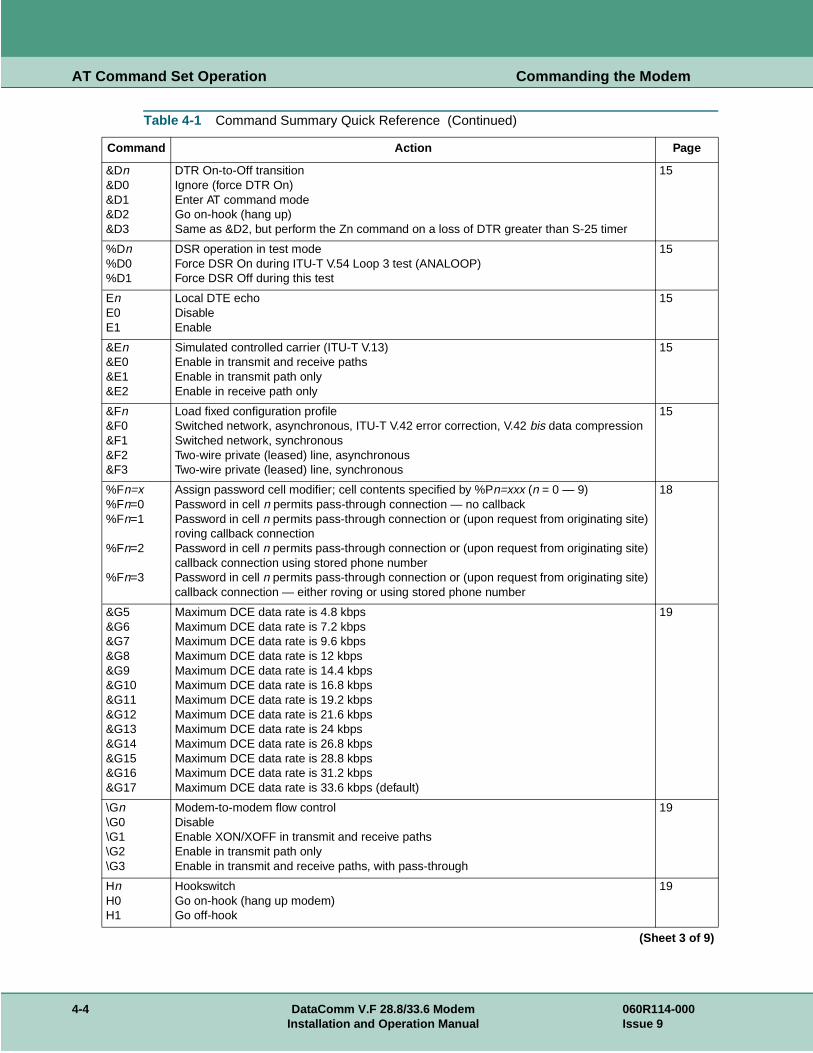
AT Command Set Operation Commanding the Modem
&Dn&D0&D1&D2&D3
DTR On-to-Off transitionIgnore (force DTR On)Enter AT command modeGo on-hook (hang up)Same as &D2, but perform the Zn command on a loss of DTR greater than S-25 timer
15
%Dn%D0%D1
DSR operation in test modeForce DSR On during ITU-T V.54 Loop 3 test (ANALOOP)Force DSR Off during this test
15
EnE0E1
Local DTE echoDisableEnable
15
&En&E0&E1&E2
Simulated controlled carrier (ITU-T V.13)Enable in transmit and receive pathsEnable in transmit path onlyEnable in receive path only
15
&Fn&F0&F1&F2&F3
Load fixed configuration profileSwitched network, asynchronous, ITU-T V.42 error correction, V.42 bis data compressionSwitched network, synchronousTwo-wire private (leased) line, asynchronousTwo-wire private (leased) line, synchronous
15
%Fn=x%Fn=0%Fn=1
%Fn=2
%Fn=3
Assign password cell modifier; cell contents specified by %Pn=xxx (n = 0 — 9)Password in cell n permits pass-through connection — no callbackPassword in cell n permits pass-through connection or (upon request from originating site) roving callback connectionPassword in cell n permits pass-through connection or (upon request from originating site) callback connection using stored phone numberPassword in cell n permits pass-through connection or (upon request from originating site) callback connection — either roving or using stored phone number
18
&G5&G6&G7&G8&G9&G10&G11&G12&G13&G14&G15&G16&G17
Maximum DCE data rate is 4.8 kbpsMaximum DCE data rate is 7.2 kbpsMaximum DCE data rate is 9.6 kbpsMaximum DCE data rate is 12 kbpsMaximum DCE data rate is 14.4 kbpsMaximum DCE data rate is 16.8 kbpsMaximum DCE data rate is 19.2 kbpsMaximum DCE data rate is 21.6 kbpsMaximum DCE data rate is 24 kbpsMaximum DCE data rate is 26.8 kbpsMaximum DCE data rate is 28.8 kbps Maximum DCE data rate is 31.2 kbpsMaximum DCE data rate is 33.6 kbps (default)
19
\Gn\G0\G1\G2\G3
Modem-to-modem flow controlDisableEnable XON/XOFF in transmit and receive pathsEnable in transmit path onlyEnable in transmit and receive paths, with pass-through
19
HnH0H1
HookswitchGo on-hook (hang up modem)Go off-hook
19
Table 4-1 Command Summary Quick Reference (Continued)
Command Action Page
(Sheet 3 of 9)
4-4 DataComm V.F 28.8/33.6 Modem 060R114-000Installation and Operation Manual Issue 9

AT Command Set Operation Commanding the Modem
%Hn
%H0
Private line heartbeat; sets value for transmission of the heartbeat on an idle line (from 1 - 255 in 30-second increments)Disabled
20
&Hn&H0&H1&H2&H3&H4&H5&H6&H7&H8&H9&H10
Switched network handshake modeV.34 auto (33.6 kbps to 300 bps)V.34 only (33.6 kbps to 2400 bps)ITU-T V.32 bis automatic (14.4 kbps to 300 bps)ITU-T V.32 bis only (14.4 kbps to 4800 bps)ITU-T V.32 automatic (9600 bps to 300 bps)ITU-T V.32 only (9600 bps to 4800 bps)ITU-T V.22 bis only (2400 bps to 1200 bps)ITU-T V.22 only (1200 bps)Bell 212 only (1200 bps)Bell 103 only (300 bps)ITU-T V.21 only (300 bps)
20
*H MNP link negotiation; controls the connection speed for link negotiations before up-shift occurs between two MNP10 modems
20
InI0I1I2I3I4I5
Identification and checksumDisplay product codeDisplay calculated checksum(Reserved for future use)Display modem's firmware revision levelDisplay listing of modem feature informationDisplay modem's serial number
20
&In&I0&I1
Front panel lockoutFront panel buttons enabledFront panel buttons disabled
20
%Kn%K0%K1
Character abort2-second delay to character abortDisable
21
\Kn\K0\K1\K2\K3\K4\K5
Break character handlingExpedite break; destroy buffersExpedite break; save buffersTimed break; save buffersIgnore breakTimed break until no break character; save buffersTimed break until no break character; save buffers
21
&L0&L1&L2
Switched networkTwo-wire private (leased) lineFour-wire private (leased) line
21
&Mn&M0&M1
Operating modeAsynchronous data modeAsynchronous command mode/synchronous data mode, with DTR-to-data delay (S-Register 25)
21
-Mn MNP10 mode 22
)Mn Cellular power level adjustment 22
@Mn Initial cellular power level settings 22
N? Country code. Displays modem’s current country code configuration 22
Table 4-1 Command Summary Quick Reference (Continued)
Command Action Page
(Sheet 4 of 9)
060R114-000 DataComm V.F 28.8/33.6 Modem 4-5Issue 9 Installation and Operation Manual

AT Command Set Operation Commanding the Modem
\Nn\N0\N1\N2\N3\N4\N5\N6
Asynchronous protocolWire modeDirect ITU-T V.14 asynchronous modeMNP reliable mode (or drop call)V.42/MNP auto reliableV.42 (LAPM) reliable mode (or drop call)V.42 (LAMP)/MNP reliable or MNP mode (or drop call)Simulated controlled carrier (ITU-T V.13)
22
OnO0O1
On-lineGo on-line (enter data mode)Go on-line and retrain (at any speed except 300 bps)
23
%On%O0%O1%O2
Answer modeAnswer mode if ringingForce to answer modeAutomatic answer in originate mode
23
PP
Dialing typePulse (rotary) dial
23
%Pn%Pn=xxx%Pn
Store password in non-volatile memoryDefine password in cell n (n = 0 — 9; xxx = 1 to 10 characters)Clear password in cell n
23
&Pn&P0&P1&P2&P3&P4
Private (leased) line handshake modeV.34 only (28.8 kbps to 2400 bps)ITU-T V.32 bis only (14.4 kbps to 4800 bps)ITU-T V.32 only (9600 bps to 4800 bps)IUT-T 212 only (1200)ITU-T 103 only (300 bps)
23
*Pn Remote configuration security password (n=1 to 11 characters) 24
\Pn\P0\P1\P2\P3\P4
Parity typeEvenSpaceOddMarkAutomatic (from last AT command)
23
:Pn:P0:P1
Switched network transmit typePermissiveProgrammable
24
QnQ0Q1Q2
Response modeEnableDisable (enable quiet mode)Disable in answer mode only
24
\Qn\Q0\Q1\Q2\Q3\Q4\Q5\Q6
Modem-to-DTE flow controlDisable in both directionsUse XON/XOFF in both directionsUse CTSUse RTS/CTSUse XON/XOFF from modem to DTE onlyUse Clock StoppingUse Clock Throttling
24
Table 4-1 Command Summary Quick Reference (Continued)
Command Action Page
(Sheet 5 of 9)
4-6 DataComm V.F 28.8/33.6 Modem 060R114-000Installation and Operation Manual Issue 9

AT Command Set Operation Commanding the Modem
%Q%Q0%Q1%Q2
Retrain on poor signal qualityDisableAttempt up to 3 consecutive retrains; disconnect if not successfulRetrain until signal quality is good
24
*Rn*R0*R1
Remote configuration write accessEnable write access (read/write)Disable write access (read only)
25
&Rn&R0
&R1
CTS operationSynchronous mode: RTS-CTS delayAsynchronous mode: On in command modeAT command mode: Force CTS OnSynchronous mode: RealAsynchronous mode: On in command modeAT command mode: Force CTS On
25
&R2
&R3
Synchronous mode: Real Asynchronous mode: RealAT command mode: RealSynchronous mode: Force CTS OnAsynchronous mode: Force CTS OnAT command mode: Force CTS On
25
%Rn%R0%R1%R2%R3%R4%R5%R6%R7%R8%R9%R10%R11%R12%R13%R14%R15%R16%R17%R18%R19%R20%R21%R22%R23%R24%R25%R26%R27%R28%R29
Call Progress Monitor (CPM) message response speed Auto speedSend at last AT speed300 bps1200 bps2400 bps4800 bps7200 bps9600 bps12.0 kbps14.4 kbps16.8 kbps19.2 kbps21.6 kbps24.0 kbps26.4 kbps28.8 kbps31.2 kbps33.6 kbps38.4 kbps57.6 kbps76.8 kbps115.2 kbps128.0 kbps32.0 kbps48.0 kbps56.0 kbps64.0 kbps72.0 kbps96.0 kbps112.0 kbps
25
Table 4-1 Command Summary Quick Reference (Continued)
Command Action Page
(Sheet 6 of 9)
060R114-000 DataComm V.F 28.8/33.6 Modem 4-7Issue 9 Installation and Operation Manual
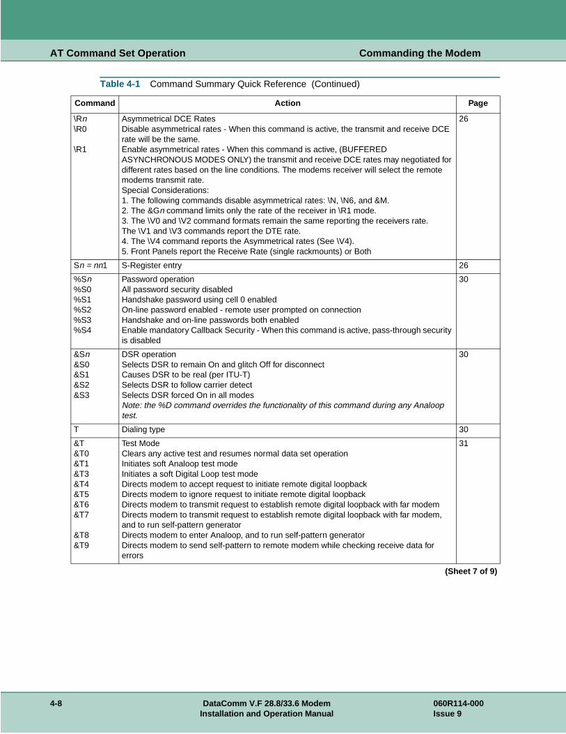
AT Command Set Operation Commanding the Modem
\Rn\R0
\R1
Asymmetrical DCE RatesDisable asymmetrical rates - When this command is active, the transmit and receive DCE rate will be the same.Enable asymmetrical rates - When this command is active, (BUFFERED ASYNCHRONOUS MODES ONLY) the transmit and receive DCE rates may negotiated for different rates based on the line conditions. The modems receiver will select the remote modems transmit rate.Special Considerations:1. The following commands disable asymmetrical rates: \N, \N6, and &M.2. The &Gn command limits only the rate of the receiver in \R1 mode.3. The \V0 and \V2 command formats remain the same reporting the receivers rate.The \V1 and \V3 commands report the DTE rate.4. The \V4 command reports the Asymmetrical rates (See \V4).5. Front Panels report the Receive Rate (single rackmounts) or Both
26
Sn = nn1 S-Register entry 26
%Sn%S0%S1%S2%S3%S4
Password operationAll password security disabledHandshake password using cell 0 enabledOn-line password enabled - remote user prompted on connectionHandshake and on-line passwords both enabledEnable mandatory Callback Security - When this command is active, pass-through security is disabled
30
&Sn&S0&S1&S2&S3
DSR operationSelects DSR to remain On and glitch Off for disconnectCauses DSR to be real (per ITU-T)Selects DSR to follow carrier detectSelects DSR forced On in all modesNote: the %D command overrides the functionality of this command during any Analoop test.
30
T Dialing type 30
&T&T0&T1&T3&T4&T5&T6&T7
&T8&T9
Test ModeClears any active test and resumes normal data set operationInitiates soft Analoop test modeInitiates a soft Digital Loop test modeDirects modem to accept request to initiate remote digital loopbackDirects modem to ignore request to initiate remote digital loopbackDirects modem to transmit request to establish remote digital loopback with far modemDirects modem to transmit request to establish remote digital loopback with far modem, and to run self-pattern generatorDirects modem to enter Analoop, and to run self-pattern generatorDirects modem to send self-pattern to remote modem while checking receive data for errors
31
Table 4-1 Command Summary Quick Reference (Continued)
Command Action Page
(Sheet 7 of 9)
4-8 DataComm V.F 28.8/33.6 Modem 060R114-000Installation and Operation Manual Issue 9

AT Command Set Operation Commanding the Modem
\Tn\T0\T1\T2\T3\T4\T5\T6\T7\T8\T9\T10\T11\T12\T13\T14\T15\T16\T17\T18\T19\T20\T21\T22\T23\T24\T25\T26\T27\T28\T29
DTE speed Auto speedSend at last AT speed300 bps1200 bps2400 bps4800 bps7200 bps9600 bps12.0 kbps14.4 kbps16.8 kbps19.2 kbps21.6 kbps24.0 kbps26.4 kbps28.8 kbps31.2 kbps33.6 kbps38.4 kbps57.6 kbps76.8 kbps115.2 kbps128.0 kbps32.0 kbps48.0 kbps56.0 kbps64.0 kbps72.0 kbps96.0 kbps112.0 kbps
31
:Tn Private line transmit level 32
%Tn
%T0
Inactivity timer, disconnect after selected period of inactivity (1 - 255 in 1-minute increments)Disabled
32
&Un&U0&U1
Trellis codingEnables Trellis codingDisables Trellis coding
32
\Vn\V0
\V1\V2
\V3
Connect message typeConnect message reports VF rate upon data mode, link message after link negotiation (GDC format)Connect and protocol message sent after link negotiation, connect reported as DTE rateConnect and protocol message after link negotiation and Microcom compatible, connect reported as VF rateConnect message only after protocol negotiation, connect reported as DTE rate
33
%Vn%V0%V1%V2%V3%V4
Command formatAT command setV.25 bis asynchronous command setV.25 bis HDLC command setV.25 bis BSC command setNone
33
Table 4-1 Command Summary Quick Reference (Continued)
Command Action Page
(Sheet 8 of 9)
060R114-000 DataComm V.F 28.8/33.6 Modem 4-9Issue 9 Installation and Operation Manual

AT Command Set Operation Commanding the Modem
*Wn*W0*W1
Remote configuration controlDisable remote configurationEnable remote configuration
36
&Wn Save option settings as user configuration profile n in non-volatile RAM (n=0 to 3) 36
XnX0X1X2X3X4X5
Call progress Monitor (CPM)CONNECT message only; disable CPMCONNECT message with speed; disable CPMCONNECT message with speed; and pre-dial CPM onlyCONNECT message with speed; and post dial CPM onlyCONNECT message with speed; full CPM CONNECT message with speed; full CPM and ringback detect
36
YnY0Y1
Long space disconnectDisableEnable
37
&Xn&X0&X1&X3
Transmit clock sourceInternal clock (modem)External clock (DTE)Receiver wrap clock (network)
36
*Xn*X0*X1
Remote configuration exitTerminate session without saving changesTerminate session and save changes
37
&Yn&Yn
Power-up user configuration profileLoad user configuration profile n at power up (n = 0 to 3)
36
ZnZn
Load user configuration profileRecall (load) user-defined configuration profile n (n = 0 to 3). Storable S-Registers are stored with user-defined settings.
37
&Zn=nnn&Zn=nnn
Store a phone numberStore phone number nnn (including dial command modifiers) in cell n (n = 0 to 9)
37
%Zn%Z0%Z1=x%Z2%Z3=x
DTR dialingIgnore DTRDial cell x on DTR Off-to-On transitionGo off-hook on DTR Off-to-On transition and attempt handshakeDial cell x on DTR Off-to-On transition; redial if needed while DTR remains On
37
Table 4-1 Command Summary Quick Reference (Continued)
Command Action Page
(Sheet 9 of 9)
4-10 DataComm V.F 28.8/33.6 Modem 060R114-000Installation and Operation Manual Issue 9

AT Command Set Operation AT Command Reference
e only f each d to-
AT Command ReferenceAll commands are assumed to be preceded by an AT and followed by a carriage return. Thexception is the A/ command, which is used to repeat the last AT command. A description ocommand follows. They are organized alphabetically, with all variations of the letter groupegether as follows:
• The basic AT command.
• The extended AT& command.
• The extended AT% command.
• The extended AT\ command.
• The extended AT: command.
• The extended AT* command.
Not every letter of the alphabet has a command for each of these groups
$ AT command set helpThis command causes the modem to display the help menu for the basic AT command set.
&$ AT& command set helpThis command causes the modem to display the help menu for the extended AT& command set.
%$ AT% command set helpThis command causes the modem to display the help menu for the extended AT% command set.
\$ AT\ command set helpThis command causes the modem to display the help menu for the extended AT\ command set.
:$ AT: command set helpThis command causes the modem to display the help menu for the extended AT: command set.
*$ AT* command set helpThis command causes the modem to display the help menu for the extended AT* command set.
S$ S-Register helpThis command causes the modem to display the S-Register help menu. Only S-Registers not containing bit mapped options will be displayed.
A Answer callThe A command directs the modem to answer an incoming call. It is used to go off-hook and generate the proper answer sequence.
060R114-000 DataComm V.F 28.8/33.6 Modem 4-11Issue 9 Installation and Operation Manual

AT Command Set Operation AT Command Reference
&An Automatic fallback/fallforwardThis command controls the automatic fallback and fallforward capabilities.
&A0 disables the fallforward/fallback feature.
&A1 enables the fallforward/fallback feature. The &A1 command functions only when the modem is optioned for synchronous data mode or for asynchronous with speed buffering, and only for V.34, V.32, and V.32 bis modes.
%An Auto-reliable fallback characterThis command selects the modem's auto-reliable fallback character, specified by a number between 0 and 127. The fallback character is an ASCII character (alphanumeric, punctuation, or control) that the modem will check for when it performs auto-answer and attempts to negotiate an auto-reliable (\N3) error correcting link on the VF line. If the modem detects two successive fallback characters, it will terminate the negotiation process and go directly to a non-error correcting mode. The \C command determines which non-error correcting mode (wire or direct) the modem will fall back to, and what will become of data transferred to the modem during the negotiation process.
Appendix E contains a table that lists the ASCII characters and their corresponding numeric values. Note that fallback character detection is case-sensitive, since upper and lower case letters are separate ASCII characters.
\An Overspeed correctionThis option selects overspeed correction for V.14 asynchronous data modes.
\A0 selects 1.25% (nominal) overspeed correction.
\A1 selects 2.5% (extended) overspeed correction.
A/ Repeat commandThe A/ command, the only command not preceded by an AT, is used to re-execute the most recent AT command line sent to the modem. This command can be used to cause redial of a previous number when a handshake attempt fails.
&Bn Auto Dial RestoralThis command controls Auto Dial Restoral. Refer also to the Auto Dial Restoral feature description.
&B0 disable Auto Dial Restoral.
&B1 enable Auto Dial Restoral, with line failure indicator.
&B2 enable Auto Dial Restoral, without line failure indicator.
%Bn Make busyThis command controls the make busy option as follows:
%B0 make busy disabled.
%B1 make busy on loss of DTR.
%B2 make busy in ANALOOP.
%B3 make busy on loss of RTS, loss of DTR, or in ANALOOP.
%B4 make busy on loss of RTS.
4-12 DataComm V.F 28.8/33.6 Modem 060R114-000Installation and Operation Manual Issue 9

AT Command Set Operation AT Command Reference
\Bn Character lengthThis command sets up the character length and format the modem uses in data mode for front ends that do not send AT commands. The character length includes start, data, parity, and stop bits. Default is \B2.
\B0 character length = 8 bits (6 data)
\B1 character length = 9 bits (7 data)
\B2 character length = 10 bits (7 data, 1 parity). With automatic parity enabled (\P4), this also accommodates 8 data bits with no parity.
\B3 character length = 10 bits (8 data)
\B4 character length = 11 bits (7 data, parity, 2 stop)
\B5 character length = 11 bits (8 data, parity).
Note The V.42 and MNP protocols (\N2 through \N5) do not support 11-bit character lengths (\B4 and \B5).
&Cn DCD operationThe &Cn command controls the EIA Data Carrier Detect signal.
&C0 selects DCD to be forced On.
&C1 selects DCD to be real (follow modem energy detect).
&C2 selects DCD to be forced On in Command mode, and real in Data mode.
%Cn Data compressionThis option controls the selection of data compression for MNP-5 reliable, V.42 bis reliable, and synchronous data links.
%C0 disables data compression.
%C1 enables data compression in both directions.
%C2 in V.42 bis or synchronous, enables data compression in the transmitter path. In MNP 5, enables data compression in both directions.
%C3 in V.42 bis or synchronous, enables data compression in the receiver path. In MNP 5, enables data compression in both directions.
\Cn Fallback selection and pre-link data bufferThis command determines fallback selection. If an error correcting protocol is enabled, this command determines whether incoming data from the remote modem will be buffered while the receiver modem waits for establishment of the error correction link.
\C0 Receiver modem discards all incoming VF data from the remote modem until it has sent a PROTOCOL: NONE message to its DTE. Receiver modem then passes data through.
\C1 Receiver modem buffers incoming VF data (up to 200 characters) until it has sent a PROTOCOL: NONE message to its DTE. It then passes the buffered data through to the DTE. The modem will fall back to wire mode if more than 200 characters are received before an error correction link is established.
\C2 Receiver modem discards all incoming VF data until it detects two consecutive fallback characters (%An). At that point it falls back to wire mode. The receiver modem passes one fallback character through to its DTE as data.
060R114-000 DataComm V.F 28.8/33.6 Modem 4-13Issue 9 Installation and Operation Manual

AT Command Set Operation AT Command Reference
\C3 Same as \C1, except that with no link the modem will fall back to V.14 (direct) mode.
\C4 Same as \C2, except that with no link the modem will fall back to V.14 (direct) mode.
Dn DialThe Dn command is used to initiate a phone number dial. This command, followed by the number to be dialed, directs the modem to go off-hook and dial the number (nÖ). Commands other than dial modifiers must not be placed after the D command. Any command that is placed after the D is either ignored or interpreted as a dial command modifier.
Dial Command Modifiers:
T Selects the numbers to be tone dialed.
P Selects the numbers to be pulse dialed (if permitted by country code.
Sn Selects a stored phone number to be recalled and dialed. The modem's default when the AT command DS is issued is to dial the phone number stored in cell 0. (n = 0 to 9)
R Switches modem operation to handshake in the answer mode when this command appears as the last character in the dial string.
, or < Pauses dialing for a programmable length of time determined by S-Register 8. Default is 2 seconds.
W Directs the dialer to wait for a dial tone before continuing the dial string.
@ Directs the dialer to wait for a quiet answer before continuing the dial string.
! Directs the dialer to place a 1/2 second hook-switch flash in the dial string.
; Directs the dialer to return the modem to command mode.
:n Directs the dialer to redial the attempted dial string up to n times if the modem does not achieve data mode.
Ln Directs the dialer to dial phone cell n if the modem fails to achieve data mode with the current dial string.
\n Remote modem uses cell n for Security Callback.
A Causes the DTMF A tone to be generated.
B Causes the DTMF B tone to be generated.
C Causes the DTMF C tone to be generated.
D Causes the DTMF D tone to be generated.
0 - 9 Tone or pulse dial the appropriate number.Note: A, B, C, and D are ignored in Pulse mode
J Performs MNP10 link negotiations at 1200 bps (this call only). See *H.
K Enables power level adjustment during MNP10 link negotiation (this call only). See )M command.
4-14 DataComm V.F 28.8/33.6 Modem 060R114-000Installation and Operation Manual Issue 9

AT Command Set Operation AT Command Reference
&Dn DTR On-to-Off transitionThe &Dn command controls the result of On-to-Off transitions of Data Terminal Ready.
&D0 Causes the modem to ignore Off transitions and forces internal DTR On.
&D1 Causes the modem to change to command mode when it senses an Off transition during an established data link.
&D2 Causes the modem to recognize Off transitions of DTR and respond by hanging up.
&D3 Functions the same as &D2, and additionally causes the modem to perform AT command Z.
%Dn DSR operation in test modeThis command specifies whether Data Set Ready (DSR) will be On or Off during an ANALOOP test.
%D0 DSR will turn On whenever the modem is operating an ANALOOP test.
%D1 DSR forced Off when in an ANALOOP test.
En Local DTE echoThe En command controls the status of local echo.
E0 Turns the local echo Off.
E1 Turns the local echo On.
&En Simulated controlled carrierThe &En command controls the selection of V.13 modes.
&E0 Selects Bi-directional V.13.
&E1 Selects V.13 TX side enabled.
&E2 Selects V.13 RX side enabled.
%En DTE interface-controlled testsThis option determines whether or not tests can be controlled by DTE interface leads.
%E0 Tests cannot be commanded by signals on the DTE interface.
%E1 The modem will perform the ANALOOP (AL) test under command of Pin 18 of the DTE interface, and will perform the remote digital loop (RDL) test under command of Pin 21.
&Fn Load fixed configuration profileThe &Fn command loads the modem with factory-defined settings for a fixed configuration profile. Table 4-10 lists the settings for the four fixed configuration profiles.
&F0 Selects asynchronous switched network operation, with V.42 error correction and V.42 bis data compression.
&F1 Selects synchronous switched network operation.
&F2 Selects asynchronous two-wire private line operation.
&F3 Selects synchronous two-wire private line operation.
060R114-000 DataComm V.F 28.8/33.6 Modem 4-15Issue 9 Installation and Operation Manual

AT Command Set Operation AT Command Reference
Table 4-2 Fixed Configuration Profile Settings
Opti on (AT Command) Fixed Prof ile 0 Fixed Prof ile 1 Fixed Profil e 2 Fixed Prof ile 3
Answer mode (%O) Ans. mode if ringing (%O0)
Ans. mode if ringing (%O0)
Ans. mode if ringing (%O0)
Ans. mode if ringing (%O0)
Asymmetrical DCE rates (\R) Enable (\R1) Enable (\R1) Enable (\R1) Enable (\R1)
Asynchronous protocol (\N) Auto-reliable (\N3)
Auto-reliable (\N3)
Auto-reliable(\N3)
Auto-reliable (\N3)
Auto Dial Restoral (&B) Disable (&B0) Disable (&B0) Disable (&B0) Disable (&B0)
Auto-reliable fallback char. (%A) "CR” (%A13) "CR” (%A13) "CR” (%A13) "CR” (%A13)
Automatic fallforward/fallback (&A) Disable (&A0) Disable (&A0) Disable (&A0) Disable (&A0)
Break character handling (\K) See \K5 See \K5 See \K5 See \K5
Call Progress Monitor (X) Ext. results/full CPM (X4)
Ext. results/full CPM (X4)
Ext. results/full CPM (X4)
Ext. results/full CPM (X4)
Cellular Power Adjust )M Disabled )M0 Disabled )M0 Disabled )M0 Disabled )M0
Character abort (%K) 2-sec. delay (%K0)
Disable (%K1)
2-sec. delay (%K0)
Disable (%K1)
Character length (\B) See \B2 See \B2 See \B2 See \B2
Connect message type (\V) See \V3 See \V3 See \V3 See \V3
Country code (N?) USA (001) USA (001) USA (001) USA (001)
CPM message response speed (%R) Autobaud speed (%R0)
Autobaud speed (%R0)
Autobaud speed (%R0)
Autobaud speed (%R0)
CTS operation (&R) See &R1 See &R2 See &R2 See &R2
Data compression (%C) Enable both ways (%C1)
Enable both ways (%C1)
Enable both ways (%C1)
Enable both ways (%C1)
DCD operation (&C) Real mode (&C1) Real mode (&C1) Real mode (&C1) Real mode (&C1)
DCE rate limit (&G) 33.6 kbps max (&G17)
33.6 kbps max (&G17)
33.6 kbps max (&G17)
33.6 kbps max (&G17)
Dialing type (P, T) Tone (T) Tone (T) Tone (T) Tone (T)
DSR operation (&S) Normal (&S1) Normal (&S1) Normal (&S1) Normal (&S1)
DSR operation in test mode (%D) Forced Off (%D1) Forced Off (%D1) Forced Off (%D1) Forced Off (%D1)
DTE interface-controlled tests (%E) Disable (%E0) Disable (%E0) Disable (%E0) Disable (%E0)
DTE speed (\T) Last AT speed (\T1)
Autobaud (\T0) Last AT speed (\T1)
Autobaud (\T0)
DTR dialing (%Z) Disable (%Z0) Disable (%Z0) Disable (%Z0) Disable (%Z0)
DTR On-to-Off transition (&D) Ignore (&D0) Go on-hook (&D2)
Go on-hook (&D2)
Go on-hook (&D2)
Front panel lockout (&I) Enable (&I 0) Enable (&I 0) Enable (&I 0) Enable (&I 0)
Heart Beat Timer (%H) Disabled (%H0) Disabled (%H0) Disabled (%H0) Disabled (%H0)
Inactivity Timer (%T) Disabled (%T0) Disabled (%T0) Disabled (%T0) Disabled (%T0)
Initial Power Level Setting (@M) -26 dBm (@M1) -26 dBm (@M1) -26 dBm (@M1) -26 dBm (@M1)
Local DTE echo (E) Enable (E1) Enable (E1) Disable (E0) Disable (E0)
Long space disconnect (Y) On (Y1) On (Y1) On (Y1) On (Y1)
(Sheet 1 of 3)
4-16 DataComm V.F 28.8/33.6 Modem 060R114-000Inst alla tion and Op eratio n Manual Issue 9

AT Command Set Operation AT Command Reference
Make busy (%B) Disable (%B0) Disable (%B0) Disable (%B0) Disable (%B0)
MNP 10 (-M) Disabled (-M0) Disabled (-M0) Disabled (-M0) Disabled (-M0)
MNP Link Negotiation Speed (*H) Highest Rate (*H0)
Highest Rate (*H0)
Highest Rate (*H0)
Highest Rate (*H0)
Modem-to-DTE flow control (\Q) Use CTS (\Q2) Use CTS (\Q2) Use CTS (\Q2) Use CTS (\Q2)
Modem-to-modem flow control (\G) Disable (\G0) Disable (\G0) Disable (\G0) Disable (\G0)
Network type (&L) Switched network (&L0)
Switched network (&L0)
Two-wire private line (&L1)
Two-wire private line (&L1)
Operating mode (&M) Async data (&M0) Sync data (&M1) Async data (&M0) Sync data (&M1)
Overspeed correction (\A) Nominal (\A0) Nominal (\A0) Nominal (\A0) Nominal (\A0)
Parity type (\P) Auto (\P4) Auto (\P4) Auto (\P4) Auto (\P4)
Pre-link data buffer (\C) See \C2 See \C2 See \C2 See \C2
Private line handshake mode (&P) V.34 only (&P0) V.34 only (&P0) V.34 only (&P0) V.34 only (&P0)
Private line transmit level (:T) -9 dBm (:T9) -9 dBm (:T9) -9 dBm (:T9) -9 dBm (:T9)
RDL options (&T4, &T5) Disable RDL (&T5)
Disable RDL (&T5)
Disable RDL (&T5)
Disable RDL (&T5)
Remote config write access (*R) Enable (*R0) Enable (*R0) Enable (*R0) Enable (*R0)
Response mode (Q) Result codes (Q0) Quiet (Q1) Quiet (Q1) Quiet (Q1)
Result code type (V) Verbal (V1) Verbal (V1) Verbal (V1) Verbal (V1)
Retrain on poor signal quality (%Q) Until SQ is good (%Q2)
Until SQ is good (%Q2)
Until SQ is good (%Q2)
Until SQ is good (%Q2)
DSR operation (&S) Normal (&S1) Normal (&S1) Normal (&S1) Normal (&S1)
S-Registers (S) Decimal (ASCII)
0 Rings to answer on 1 (S0=1) 1 (S0=1) 1 (S0=1) 1 (S0=1)
2 Escape code character 43 (+) (S2=43) 43 (+) (S2=43) 43 (+) (S2=43) 43 (+) (S2=43)
3 Carriage return character 13 (CR) (S3=13) 13 (CR) (S3=13) 13 (CR) (S3=13) 13 (CR) (S3=13)
4 Line feed character 10 (LF) (S4=10) 10 (LF) (S4=10) 10 (LF) (S4=10) 10 (LF) (S4=10)
5 Back space character 08 (BS) (S5=08) 08 (BS) (S5=08) 08 (BS) (S5=08) 08 (BS) (S5=08)
6 Wait for dial tone 2 sec. (S6=2) 2 sec. (S6=2) 2 sec. (S6=2) 2 sec. (S6=2)
7 Wait for carrier for W and @ 60 sec. (S7=60) 60 sec. (S7=60) 60 sec. (S7=60) 60 sec. (S7=60)
8 Pause time for , or < 2 sec. (S8=2) 2 sec. (S8=2) 2 sec. (S8=2) 2 sec. (S8=2)
9 Carrier detect response time 0.6 sec. (S9=6) 0.6 sec. (S9=6) 0.6 sec. (S9=6) 0.6 sec. (S9=6)
10 Loss of carrier to hang up delay 1.4 sec. (S10=14) 1.4 sec. (S10=14) 1.4 sec. (S10=14) 1.4 sec. (S10=14)
12 Escape sequence guard time 1 sec. (S12=50) 1 sec. (S12=50) 1 sec. (S12=50) 1 sec. (S12=50)
18 Modem test timer 0 sec. (S18=0) 0 sec. (S18=0) 0 sec. (S18=0) 0 sec. (S18=0)
25 Delay to DTR 0.05 sec. (S25=5) 0.05 sec. (S25=5) 0.05 sec. (S25=5) 0.05 sec. (S25=5)
25 Delay to DTR%V0 or %V1 with sync data mode
5 sec. (S25=5) 5 sec. (S25=5) 5 sec. (S25=5) 5 sec. (S25=5)
26 RTS/CTS delay 0 sec. (S26=0) 0 sec. (S26=0) 0 sec. (S26=0) 0 sec. (S26=0)
38 Hang-up delay timer 20 sec. (S38=20) 20 sec. (S38=20) 20 sec. (S38=20) 20 sec. (S38=20)
40 Private line down timer 1 min. (S40=1) 1 min. (S40=1) 1 min. (S40=1) 1 min. (S40=1)
Table 4-2 Fixed Configuration Profile Settings (Continued)
Option (AT Command) Fixed Profile 0 Fixed Profile 1 Fixed Profile 2 Fixed Profile 3
(Sheet 2 of 3)
060R114-000 DataComm V.F 28.8/33.6 Modem 4-17Issue 9 Installation and Operation Manual

AT Command Set Operation AT Command Reference
41 Private line lookback timer 1 min. (S41=1) 1 min. (S41=1) 1 min. (S41=1) 1 min. (S41=1)
42 Call failures before modem make busy (special feature, implemented only on a point-of-sale basis)
70 Max. no. of re-transmissions 100 (S70=100) 100 (S70=100) 100 (S70=100) 100 (S70=100)
Simulated controlled carrier (&E) Enable both ways (&E0)
Enable both ways (&E0)
Enable both ways (&E0)
Enable both ways (&E0)
Store password (%P) None (%P) None (%P) None (%P) None (%P)
Switched network handshake mode (&H) V.34 auto (&H0) V.34 auto (&H0) V.34 auto (&H0) V.34 auto (&H0)
Switched network transmit type (:P) Permissive (:P0) Permissive (:P0) Permissive (:P0) Permissive (:P0)
Synchronous protocol (\M) Normal (\M0) Normal (\M0) Normal (\M0) Normal (\M0)
Transmit clock source (&X) Internal (&X0) Internal (&X0) Internal (&X0) Internal (&X0)
Trellis coding (&U) Enable (&U0) Enable (&U0) Enable (&U0) Enable (&U0)
Power-up user configuration profile (&Y) User Profile 0 (&Y0)
User Profile 0 (&Y0)
User Profile 0 (&Y0)
User Profile 0 (&Y0)
Note When factory defaults are loaded in the modem, modem parameters set by the following commands are not affected: %F, H, %P, *R, %S, &V, %V, &W, *W, *X, Z, and &Z.
%Fn=x Password cell qualifierThe %Fn=x command determines which callback extension(s), if any, can be used with the password stored in a specified password memory cell. In the command, n represents the number (0 - 9) of a password memory cell.
This command does not affect use of the fixed callback extension (,F), which is administered by an MMS controller.
%Fn=0 disables the use of callback extensions with the password stored in cell n. The modem will terminate any call in which it receives that password with a callback extension attached.
%Fn=1 permits the roving callback extension (,R) to be used with the password stored in cell n. When the modem receives the ,R extension attached to the password it will prompt the remote user for a callback phone number and then perform the callback procedure. The password can be used without an extension, but the use of any extension other than ,R will cause the modem to terminate the connection.
%Fn=2 permits the phone cell callback extension (,C) to be used with the password stored in cell n. When the modem receives the ,C extension attached to the password it will prompt the remote user for the number of a phone number memory cell in the answering modem. The answering modem will then use the phone number stored in that memory cell to perform the callback procedure. The password can be used without an extension, but the use of any extension other than ,C will cause the modem to terminate the connection.
Table 4-2 Fixed Configuration Profile Settings (Continued)
Option (AT Command) Fixed Profile 0 Fixed Profile 1 Fixed Profile 2 Fixed Profile 3
(Sheet 3 of 3)
4-18 DataComm V.F 28.8/33.6 Modem 060R114-000Installation and Operation Manual Issue 9

AT Command Set Operation AT Command Reference
%Fn=3 permits the use of either the roving (,R) or phone cell (,C) callback extension with the password stored in cell n. When the modem receives an extension attached to the password it will issue the appropriate prompt to the remote user and perform the specified callback procedure. The password can be used without an extension.
&Gn DCE rate limitThis command sets the maximum rate at which the modem can make a VF connection to a remote modem when using the V. 34, V.32, and V.32 bis modulation schemes. The allowable rates for each scheme are:
V.34 - 2.4 to 28.8 kbpsV.32 only - 4.8 or 9.6 kbpsV.32 bis only - 4.8 to 14.4 kbps
If the rate specified with this command is greater than the highest rate available with the type of modulation being used, the modem will use the highest available rate. If the rate specified with this command is less than the lowest rate available with the type of modulation being used, the modem will use the lowest available rate.
&G5 4.8 kbps, maximum rate
&G6 7.2 kbps, maximum rate
&G7 9.6 kbps, maximum rate
&G8 12 kbps, maximum rate
&G9 14.4 kbps, maximum rate
&G10 16.8 kbps, maximum rate
&G11 19.2 kbps, maximum rate
&G12 21.6 kbps, maximum rate
&G13 24 kbps, maximum rate
&G14 26.4 kbps, maximum rate
&G15 28.8 kbps, maximum rate (default)
&G16 31.2 kbps, maximum rate (default)
&G17 33.6 kbps, maximum rate (default)
\Gn Modem-to-modem flow controlThis command is used to provide modem-to-modem flow control for non-error corrected data links that require a constant speed DTE interface (Wire Mode).
\G0 Disables flow control between the two modems.
\G1 Enables bidirectional modem flow control based on XON/XOFF signaling. The XON/XOFF signals are detected, acted on, and deleted from the data stream.
\G2 Provides unidirectional flow control: the modem may send XON/XOFF signals to the remote modem, yet ignore and pass through to its DTE any that it receives as VF signals.
\G3 Same as \G1, except that, after they are acted upon, XON/XOFF signals are passed through to the DTE instead of being deleted.
Hn HookswitchThe Hn command controls the off-hook relay.
H0 Opens the relay for on-hook condition (modem hang-up).
H1 Closes the relay for off-hook condition. Modem remains off-hook until termination of on-line status, or until the H0 command is issued.
060R114-000 DataComm V.F 28.8/33.6 Modem 4-19Issue 9 Installation and Operation Manual

AT Command Set Operation AT Command Reference
&Hn Switched network handshake modeControls the selection of the switched network hand-shake mode.
Note a. When the modem is optioned for an external transmit clock source (&X1), the modem should be optioned for a fixed hand-shake mode, not an automatic hand-shake mode (e.g., select V.32 bis only [&H3] instead of V.32 bis automatic [&H2]). The modem will then handshake only at the speed given to it by the DTE.
b. For 1200 bps V.22 operation, select &H7. &H6 is an auto mode, so setting the DTE to 1200 bps (\T3) will not force the connection to 1200 bps.
&H0 selects V.34 auto (28.8 - 300)
&H1 selects V.34 only (28.8 - 2400)
&H2 selects V.32 bis automatic (14.4 - 300)
&H3 selects V.32 bis only (14.4 - 4800)
&H4 selects V.32 automatic (9600 - 300)
&H5 selects V.32 only (9600 - 4800)
&H6 selects V.22 bis only (2400 - 1200)
&H7 selects V.22 only (1200)
&H8 selects 212 only (1200)
&H9 selects 103 only (300)
&H10 selects V.21 only (300)
%Hn Private line heartbeatThe Hn command sets the value, in half minute intervals, for transmissions of the H<CR>heartbeat on an idle line. n=0 to 255.
*Hn MNP10 Link Negotiation SpeedThis command controls the connection speed for link negotiations before up-shift occurs.
*H0 Link negotiations occurs at the highest supported speed.
*H1 Link negotiations occurs at 1200 bps; used primarily for establishing cellular connections.
*H2 Link negotiations occurs at 4800 bps; used primarily to negotiate an MNP10 connection on less than average quality telephone lines.
In Identification and checksumThe In command requests modem identification and checksum codes to be transmitted to the DTE.
I0 Displays the modem product code. The V.F 28.8 product code is 288.
I1 Displays the stored checksum calculated for the modem's configuration.
I2 (reserved for future use)
I3 Displays the revision level of the modem's firmware (an alphabetical character) followed by the OK message.
I4 Displays a listing of the following modem information:Firmware Level - revision level as displayed by I3Product Type - product code as displayed by I0Management System - On/Off status of MMS controlSync Compression - On/Off statusLeased Line - On/Off status; Off = modem configured for switched network only operation
4-20 DataComm V.F 28.8/33.6 Modem 060R114-000Installation and Operation Manual Issue 9
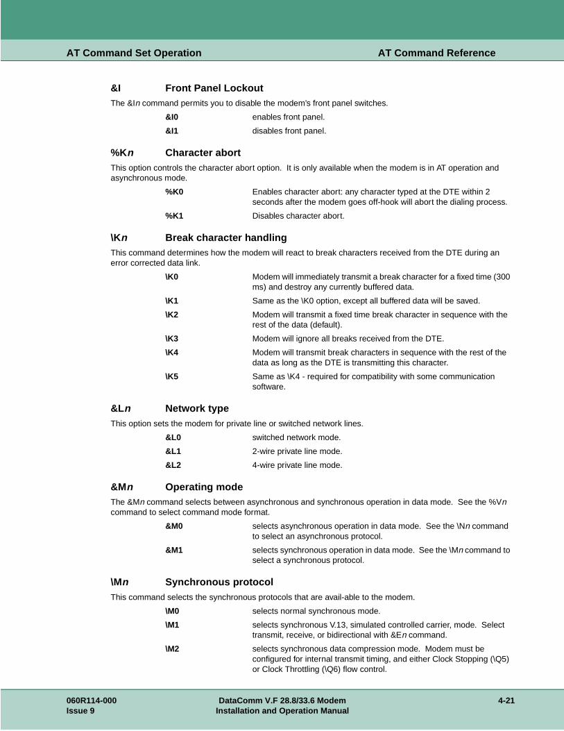
AT Command Set Operation AT Command Reference
&I Front Panel LockoutThe &In command permits you to disable the modem’s front panel switches.
&I0 enables front panel.
&I1 disables front panel.
%Kn Character abortThis option controls the character abort option. It is only available when the modem is in AT operation and asynchronous mode.
%K0 Enables character abort: any character typed at the DTE within 2 seconds after the modem goes off-hook will abort the dialing process.
%K1 Disables character abort.
\Kn Break character handlingThis command determines how the modem will react to break characters received from the DTE during an error corrected data link.
\K0 Modem will immediately transmit a break character for a fixed time (300 ms) and destroy any currently buffered data.
\K1 Same as the \K0 option, except all buffered data will be saved.
\K2 Modem will transmit a fixed time break character in sequence with the rest of the data (default).
\K3 Modem will ignore all breaks received from the DTE.
\K4 Modem will transmit break characters in sequence with the rest of the data as long as the DTE is transmitting this character.
\K5 Same as \K4 - required for compatibility with some communication software.
&Ln Network typeThis option sets the modem for private line or switched network lines.
&L0 switched network mode.
&L1 2-wire private line mode.
&L2 4-wire private line mode.
&Mn Operating modeThe &Mn command selects between asynchronous and synchronous operation in data mode. See the %Vn command to select command mode format.
&M0 selects asynchronous operation in data mode. See the \Nn command to select an asynchronous protocol.
&M1 selects synchronous operation in data mode. See the \Mn command to select a synchronous protocol.
\Mn Synchronous protocolThis command selects the synchronous protocols that are avail-able to the modem.
\M0 selects normal synchronous mode.
\M1 selects synchronous V.13, simulated controlled carrier, mode. Select transmit, receive, or bidirectional with &En command.
\M2 selects synchronous data compression mode. Modem must be configured for internal transmit timing, and either Clock Stopping (\Q5) or Clock Throttling (\Q6) flow control.
060R114-000 DataComm V.F 28.8/33.6 Modem 4-21Issue 9 Installation and Operation Manual

AT Command Set Operation AT Command Reference
MNP 10 Commands To enable MNP10 for central site operations select -M1. All other commands should be left at the default settings.
-Mn MNP10 ModeThis command enables or disables MNP10 mode.
-M0 disables MNP10.
-M1 enables MNP10 Auto Reliable mode (recommended setting).
-M2 enables MNP10 reliable mode (will not fallback to V.42/V.42bis).
)Mn Cellular Power Level AdjustmentThis command enables or disables automatic power adjustment of the transmit power level to accommodate the signaling requirements of cellular telephone equipment.
)M0 disables transmit power level adjustment during MNP10 link negotiation. The )M0 command allows the transmitter adjustment if cellular operation is requested by the remote modem (recommended).
)M1 enables transmit power level adjustment during MNP10 link negotiation. Uses the @Mn value to establish initial cellular connection. After connection, the optimal power level is determined by the modem.
Note For both cellular and land based modems in both originate or answer modes, if )M1 is set, the transmit power level used for non-MNP10 or fax connections is the @Mn value. Also, the )M1 setting should not be used when *H2 is selected.
@Mn Initial Cellular Power Level SettingsThis command sets the initial transmit power level for up-shift at connect until line conditions can be determined. Levels can be set from -10 dBm to -31 dBm.
@M0 initial transmit power level of -30 dBm (recommended).
@M1 initial transmit power level of -26 dBm.
@M2 - @M10 initial transmit power level of -10 dBm
@M11 - @M31 initial transmit power level of -11 dBm to -31 dBm, respectively.
Dial ModifiersJ perform MNP10 link negotiation at 1200 bps (this call only). See *H1
command.
K enable power level adjustment during MNP10 link negotiation (this call only). See )M1 command.
N? Country codeDisplays the current country the modem is configured for. In general, the country code displayed is the country's international calling code. Refer to Chapter 2, Table 2-1 for part numbers.
\Nn Asynchronous protocolThis command is used to select the various possible asynchronous protocols the modem is allowed to negotiate upon establishing a data link.
\N0 Options the modem to run in wire mode, performing speed buffering by copying characters from the VF port to the DTE port and vice versa.
4-22 DataComm V.F 28.8/33.6 Modem 060R114-000Installation and Operation Manual Issue 9

AT Command Set Operation AT Command Reference
\N1 Options the modem to run in direct mode: the DTE and VF speeds must match, and there is no speed buffering. Direct mode is V.14 asynchronous mode.
\N2 Limits error correction to MNP links only, or hang up.
\N3 Options the modem to run in auto reliable mode, and to negotiate V.42 or alternate links. With no link, the modem enters wire mode (speed buffering).
\N4 Limits error correction to a V.42 (LAPM) link only, or hang up.
\N5 Options the modem to attempt either a V.42 (LAPM) or MNP link. If either link fails, the modem will hang up.
\N6 Selects the use of V.13 simulated controlled carrier operation.
On On-lineThe On command directs the modem to go on-line (enter data mode) after an escape to local command mode is issued. This command transfers the modem from command mode to data mode.
O0 Tells the modem to go on-line.
O1 Tells the modem to go on-line and issue a retrain sequence if operating in V.34, V.22 bis, V32, or V32 bis modes.
%On Answer modeFor a modem being used on a switched network this option selects the band the modem will use for answering calls. The selection applies to both automatically and manually answered calls. For a modem being used on a private line, this option selects the band the modem will use for connections.
%O0 Commands the modem, in switched network mode, to use the presence of a ring to determine the band, regardless of whether the talk/data switch (the SEL key) on the front panel is used or automatic answer is selected. In private line mode, the modem will be in the originate band.
%O1 Commands the modem to answer calls in the answer band in either switched network or private line mode.
%O2 Commands the modem to answer calls in the originate band in either switched network or private line mode.
P Dialing typeThis command directs the modem to use pulse dialing as its selected dialing method. The command may be used alone or as part of a dial string. When P is used alone as a command it makes pulse dialing the modem's default - to be used unless a dial string includes a tone modifier. When P is used in a dial string, it acts as a modifier and affects only the dialing of that string. Pulse dialing is blocked by some country code configurations.
&Pn Private line handshake mode&Pn controls the selection of the private line handshake mode.
&P0 selects V.34 only (28.8 - 2400)
&P1 selects V.32 bis only (14.4 - 4800)
&P2 selects V.32 only (9600 and 4800)
&P3 selects IUT-T 212 (1200)
&P4 selects IUT-T 103 (300)
%Pn=nnn Store password
060R114-000 DataComm V.F 28.8/33.6 Modem 4-23Issue 9 Installation and Operation Manual

AT Command Set Operation AT Command Reference
This command stores a password in one of the 10 memory cells (n = 0 - 9) the modem provides for that purpose. Each password (nnn) can consist of up to 10 characters. Refer also to the Passwords feature description. nnn = password, 1 to 10 characters (to disable or clear the password, enter %P).
\Pn Parity typeThis command sets up what parity to use in data mode for front ends that do not send AT commands.
\P0 Even parity
\P1 Space parity
\P2 Odd parity
\P3 Mark parity
\P4 Automatic parity; last AT (default)
:Pn Switched network transmit typeThis command allows you to select permissive or programmable mode for switched network operation.
:P0 Selects permissive mode.
:P1 Selects programmable mode.
*Pn Remote configuration security passwordThis command defines the remote configuration security pass-word. Refer also to the Remote Configuration feature description. n = password, 1 to 11 characters (to disable or clear the password, enter *P).
Qn Response modeThe Qn command controls the transmission of result codes.
Q0 Requests non-quiet mode: result codes are transmitted to the DTE as appropriate.
Q1 Requests quiet mode: modem does not send any result codes to the DTE.
Q2 Disables Call Progress Monitor responses in answer mode only. Modem enters this mode on detection of ring signal.
%Qn Retrain on poor signal qualityThis option controls retrain initiation.
%Q0 Disables retrain initiation.
%Q1 Modem will try up to 3 consecutive retrains upon detection of poor signal quality. If not successful, the modem will disconnect the line.
%Q2 Modem will retrain on poor signal quality until signal quality is OK.
\Qn Modem-to-DTE flow controlThis command selects the type of data mode flow control used on the DTE port.
\Q0 Disables all flow control.
\Q1 Enables XON/XOFF signaling between modem and DTE.
\Q2 Enables the modem to flow control the DTE via CTS.
\Q3 Operates the same as the \Q2 option, and also allows the DTE to flow control the modem via RTS as a ready to receive signal.
\Q4 Allows the modem to XON/XOFF the DTE yet ignore these signals when sent by the DTE (unidirectional flow control).
4-24 DataComm V.F 28.8/33.6 Modem 060R114-000Installation and Operation Manual Issue 9

AT Command Set Operation AT Command Reference
\Q5 Allows the modem to flow control the DTE by almost stopping the transmit clock (internal transmit timing must be selected). Used with synchronous data compression.
\Q6 Allows the modem to flow control the DTE by varying the rate of the transmit clock (internal transmit timing must be selected). Used with synchronous data compression.
060R114-000 DataComm V.F 28.8/33.6 Modem 4-25Issue 9 Installation and Operation Manual

AT Command Set Operation AT Command Reference
&Rn CTS operationThe &Rn command defines the functionality of the Request to Send and Clear to Send EIA interchange circuits.
&R0 Causes CTS to follow RTS with an interjected delay specified in S-Register 26 when in synchronous mode. In asynchronous command mode, CTS will be On. Upon reaching asynchronous data mode, CTS will follow the applicable ITU-T specification for the modulation chosen during handshake.
&R1 Causes CTS to follow the applicable ITU-T specification in data mode (in synchronous modes, CTS will not follow RTS). In command mode, CTS will be On.
&R2 Causes CTS to follow the applicable ITU-T specification. During test modes, CTS will follow V.54 conventions. CTS does not follow RTS in data modes. CTS will go Off after the call is dropped.
&R3 Forces CTS On in all modes of operation (RTS is ignored).
Note V.13 and flow control options override &R settings for CTS
%Rn Call Progress Monitor message response speed%Rn options control the rate at which Call Progress Monitor (CPM) responses are sent to the DTE when the modem is optioned for \T0.
%R0 Auto speed %R1 last AT speed %R2 300 bps
%R3 1200 bps %R4 2400 bps %R5 4800 bps
%R6 7200 bps %R7 9600 bps %R8 12.0 kbps
%R9 14.4 kbps %R10 16.8 kbps %R11 19.2 kbps
%R12 21.6 kbps %R13 24.0 kbps %R14 26.4 kbps
%R15 28.8 kbps %R16 31.2 kbps %R17 33.6 kbps
%R18 38.4 kbps %R19 57.6 kbps %R20 76.8 kbps
%R21 115.2 kbps %R22 128.0 kbps %R23 32.0 kbps
%R24 48.0 kbps %R25 56.0 kbps %R26 64.0 kbps
%R27 72.0 kbps %R28 96.0 kbps %R29 112.0 kbps
*Rn Remote configuration write accessThis command controls remote configuration write access. Refer also to the Remote Configuration feature description.
*R0 enables write configuration access (read/write).
*R1 disables write configuration access (read only).
4-26 DataComm V.F 28.8/33.6 Modem 060R114-000Installation and Operation Manual Issue 9

AT Command Set Operation AT Command Reference
Examples:
To view the value of S-Register 2, type:
ATS2?<cr>
The response might be:
005<cr><lf>
OK<cr><lf>
To set the value of S-Register 2 to equal 5, type:
ATS2=5<cr>
To view the value of the last S-Register that was queried, type:
AT?<cr>
\Rn Asymmetrical DCE RatesThis command enables or disables asymmetrical DCE rates.
\R0 disables asymmetrical rates - when this command is active, the transmit and receive DCE rate will be the same..
\R1 enables asymmetrical rates - when this command is active, (BUFFERED ASYNCHRONOUS MODES ONLY) the transmit and receive DCE rates may be negotiated for different rates based on the line conditions. The modems receiver will select the remote modems transmit rate.
Note Special Considerations:1. \N1, \N6 and %M1 disable asymmetrical rates.2. The &G command limits only the rate of the receiver in \R1 mode.3. The \V0 and |V2 command formats remain the same reporting the receivers rate. The \V1 and \V3 commands report the DTE rate.4. The \V4 commands reports the Asymmetrical rate (see \V4).5. Front Panels report the Receive Rate (single rackmount).
Sn S-RegistersThe S command allows you to view (Sn?) or change (Sn=x) the S-Registers. The S-Registers store values for functions that are not often changed, such as timers or counters, and the ASCII values of control characters, such as Carriage Return. Table 4-11 summarizes the S-Register set. It is followed by a detailed command reference.
060R114-000 DataComm V.F 28.8/33.6 Modem 4-27Issue 9 Installation and Operation Manual

AT Command Set Operation AT Command Reference
Table 4-3 S-Register Summary
S-Reg. FunctionDefinition
Decimal ASCII Units Storable
0 Automatic answer 0 Yes
1 Ring counter 0 No
2 Escape code character 43 + No
3 Carriage return character 13 CR No
4 Line feed character 10 LF No
5 Backspace character 08 BS No
6 Dial tone wait timer 02 seconds Yes
7 Carrier wait timer; W and @ dial command modifier wait timer; ringback wait timer
30 seconds Yes
8 Dial pause timer for , and < dial command modifiers
02 seconds Yes
9 Carrier presence timer 06 0.1 second Yes
10 Carrier loss timer 14 0.1 second Yes
12 Escape code guard timer 50 0.02 second No
18 Test mode timer 00 10 seconds Yes
25 DTR delay timer - all modes 0.05 seconds Yes
- sync data, Command Format %V0 or %V1
005
26 RTS-to-CTS delay timer 00 milliseconds Yes
38 Hang-up delay timer 20 seconds Yes
40 Private line down timer 01 minutes Yes
41 Private line lookback timer 01 10 minutes Yes
42 Call failures before modem make busy (normally disabled)
70 Retransmission counter 10 Yes
100 Adjustable transmit level display dBm
4-28 DataComm V.F 28.8/33.6 Modem 060R114-000Installation and Operation Manual Issue 9

AT Command Set Operation AT Command Reference
S$ S-Register helpThis command causes the modem to display the S-Register Help Menu.
S-Register 0 Automatic answer
This register determines the number of rings the modem must detect before answering a call. It is programmable from 0 to 255. If the register value is 0, automatic answer is disabled. There is a default value of 2 rings if automatic answer is turned On.
S-Register 1 Ring counter
This register counts incoming rings detected. It increments upon each detected ring, and is cleared after 8 seconds of ring silence and Idle mode. It cannot be cleared in data mode.
S-Register 2 Escape code character
This register holds the ASCII equivalent of the Escape Code character. Its range is from 0 to 127, and the default is 43 (+). Any value above 127 effectively disables the Escape code function.
S-Register 3 Carriage return character
This register holds the ASCII equivalent of the Carriage Return character. Its range is from 0 to 127, and the default is 13 (<cr>).
S-Register 4 Line feed character
This register holds the ASCII equivalent of the Line Feed character. Its range is from 0 to 127, and the default is 10 (<lf>).
S-Register 5 Backspace character
This register holds the ASCII equivalent of the Backspace character. Its range is from 0 to 127, and the default is 08 (H).
S-Register 6 Dial tone wait timer
This register is the programmable dial tone wait timer that determines how many seconds the modem will wait for a dial tone before it starts dialing. This register applies only when blind dialing is selected (X0, X1, or X3). This register can be set from 0 to 255. The default is 2 seconds.
S-Register 7 Carrier, dial and ringback wait timer
This register stores the carrier wait time, how many seconds the modem will wait for carrier detection after dialing has been completed. The wait time set in this register is also used for the dial command modifiers W (wait for dial tone before dialing) and @ (wait for quiet answer before dialing).This register also sets the number of seconds the modem will wait for ringback when originating a call. This condition only occurs when using extended result code options X3 or X4. This register can be programmed for from 1 to 60 seconds. The default is 60 seconds.
S-Register 8 Dial pause timer
This register stores the duration, in seconds, of the pause that will occur when either of the pause dialing modifiers (, or <) is used. It can be programmed from 0 to 255. The default is 2 seconds.
S-Register 9 Carrier presence timer
The value in this register determines how many tenths of a second the carrier signal must be present following a carrier loss before the modem will turn on the EIA DCD signal to the DTE. This is called loss of carrier reacquire debounce time. The register's range is from 1 to 255. The default is 6 (0.6 second).
060R114-000 DataComm V.F 28.8/33.6 Modem 4-29Issue 9 Installation and Operation Manual

AT Command Set Operation AT Command Reference
S-Register 10 Carrier loss timer
The value in this register determines how many tenths of a second the remote carrier signal must be lost before the local modem disconnects. The delay permits the carrier to disappear momentarily without causing the modem to hang up. The register's timer range is from 1 to 254. Selecting 255 disables disconnect. The modem recognizes a carrier after a period of time specified in S9. Therefore, if the value of S10 is less than that set for S9, even a momentary loss of carrier will cause the modem to disconnect. When the modem is operating in half-duplex asynchronous mode, it ignores the value of this register.
S-Register 12 Escape code guard timer
The value in this register determines (in 50ths of a second) the Escape code guard time the modem will use to recognize a valid escape sequence. The modem constantly monitors the data stream for the occurrence of three consecutive +++ (escape code characters) within the time specified in this register. The modem will transfer from the data mode to the command mode when it detects such an occurrence. This register may be set from 1 to 255. The default is 50 (1 second).
S-Register 18 Test mode timer
The value in this register determines (in 10-second increments) how long automatically timed tests will run. It may be set from 0 (no time out, tests run until ended manually) to 60 (10 minutes). The default is 0.
S-Register 25 DTR delay timer
This register sets the delay for DTR, but its precise function depends on the modem's Operating Mode (&Mn command) and Command Format (%Vn command). When the modem is configured for asynchronous Operating Mode (&M0), the value in this register is always the time used to debounce the DTR signal. It is set in hundredths of a second (0 to 255). The default is 5 (0.05 second). When the modem is configured for synchronous Operating Mode (&M1) and an asynchronous Command Format (%V0 or %V1), this register initially sets the time available to the operator for switching the EIA cable from asynchronous equipment to synchronous equipment. It can be set from 0 to 255 seconds. The default is 5 seconds. After the whole-second timer expires, the register is then used to debounce the DTR signal, as above. The same number, stored in the register, is applied to both the whole-second and hundredth-of-a-second counts.
S-Register 26 RTS-to-CTS delay timer
The value in this register determines (in milliseconds) the amount of delay between RTS and CTS. It can be set from 0 to 255. The default value is 0.
S-Register 38 Hang-up delay timer
The value in this register determines the maximum delay (in seconds) between the modem's receipt of the command to hang up and the disconnect operation. (If the modem is configured to follow the DTR signal, an On-to-Off transition acts as a command to hang up.) This register is useful for error-control and speed-buffering communications to ensure that data in the modem buffers is sent before the connection is terminated.If this register is set between 0 and 254, the modem will wait up to that number of seconds for the remote modem to acknowledge receipt of all data buffers before hanging up. The default is 20. If all data is transmitted prior to the timeout, the response to the H0 command will be OK. If the timeout occurs before all data can be sent, the NO CARRIER (3) result code will be sent to indicate that data has been lost. If this register is set to 255, the modem does not time-out, and continues to attempt to deliver data in the buffers until the connection is lost, or the data is delivered.
S-Register 40 Private line down timer
The value in this register determines (in minutes) how long the modem will continue private line retrains before it attempts a switched network connection. It can be set from 0 (timer disabled) to 255. Refer also to the Auto Dial Restoral feature description.
4-30 DataComm V.F 28.8/33.6 Modem 060R114-000Installation and Operation Manual Issue 9

AT Command Set Operation AT Command Reference
S-Register 41 Private line lookback timer
The value in this register determines (in 10 minute increments) how long the modem will operate in switched network mode before it automatically attempts to return to private line mode. It can be set from 0 (timer disabled) to 255. When the timer is disabled, the modem does not automatically attempt to return to the private line. Refer also to the Auto Dial Restoral feature description.
S-Register 42 Call failures before modem make busy
This feature is only enabled in the modem by special arrangement between the customer and GDC. When it is enabled the modem will take itself out of service by presenting a busy signal on the telephone line when the number of consecutive failed calls equals the number configured here. It can be set from 3 to 15.
S-Register 70 Retransmission counter
The value in this register determines how many times the modem will retransmit any one frame while in an error correcting connection. The modem hangs up when it reaches the limit set by this register. It can be set from 0 to 255. The default is 100. Retransmissions become necessary when data errors introduced by noise disrupt the reception of a frame. Raising this limit may be necessary if, for example, telephone lines are extremely noisy. The retransmission delays may be undesirable, but the modem will not hang up.
S-Register 100 Adjustable transmit level display
When you issue the command S100? the value in this register displays the transmit level configured in the modem. This register is not a valid display in any country, such as the United States, that limits transmit level selections to Programmable or Permissive.
&Sn DSR operationThis command controls how the Data Set Ready EIA interchange circuit will operate.
&S0 Selects DSR to remain On and glitch Off for disconnect.
&S1 Causes DSR to be real (per ITU-T).
&S2 Selects DSR to follow carrier detect.
&S3 Selects DSR forced On in all modes.
Note The %Dn command overrides the functionality of this command during any ANALOOP test.
%Sn Password operationThis command selects what type of password security the modem will enforce.
%S0 password security disabled.
%S1 general security password enforcement enabled. This is the GDC proprietary handshake password. Originating modem transmits contents of password cell 0. Answering modem compares received password to contents of password cell 0.
%S2 on-line password enforcement enabled. Answering modem prompts remote for manually input password; checks for match in any password cell, 0 - 9.
%S3 both handshake and on-line password enforcement enabled.
T Dialing typeThis command directs the modem to use tone dialing as its selected dialing method. The command may be used alone or as part of a dial string. When T is used alone as a command it makes tone dialing the modem's default - to be used unless a dial string includes a pulse modifier. When T is used in a dial string, it acts as a modifier and affects only the dialing of that string.
060R114-000 DataComm V.F 28.8/33.6 Modem 4-31Issue 9 Installation and Operation Manual

AT Command Set Operation AT Command Reference
&Tn Test modeThe &Tn command controls the soft operation of test modes.
&T0 Clears any active test and resumes normal data set operation.
&T1 Initiates a soft ANALOOP test mode that directs all local data through the transmitter and receiver of the modem. To terminate this test, type +++ (escape sequence) followed by &T0.
&T3 Initiates a soft Digital Loop test mode that directs all received data from the remote modem to be looped back to the transmit data. This has the effect of echo on the remote DTE. Any data the remote DTE sends is returned.
&T4 Directs the modem to accept the in-band request to initiate a remote digital loopback.
&T5 Directs the modem to ignore the in-band request to initiate a remote digital loopback.
&T6 Directs the modem to transmit the in-band request to establish a remote digital loopback with the far modem.
&T7 Directs the modem to transmit the in-band request to establish a remote digital loopback with the far modem, and to run the self-test pattern generator.
&T8 Directs the modem to enter the ANALOOP test mode, and to run the self-test pattern generator.
&T9 Directs the modem to send a self-test pattern to the remote modem while checking the receive data for the same test pattern and checking for errors.All tests operate for the amount of time specified in S-Register 18. Pending tests such as DL are not allowed.The self-test pattern for speeds of 1200 and 2400 bps is made up of alternate ones and zeros; the 511 pattern is generated for all other speeds.Remote digital loopback and self-tests are not operational when the modems are passing data at 300 bps.
\Tn DTE speedThis command, in conjunction with the switched network hand-shake mode command (&Hn), controls the DTE speed. There are several configurations to consider:
a. An automatic handshake mode (e.g., V.32 bis auto [&H1], V.32 auto [&H4], V.22 bis only [&H6]) takes precedence over the \Tn selection, and the modem tries for the highest VF speed common to the two commands.
b. For 1200 bps V.22 operation, select &H7. &H6 is an auto mode, so setting the DTE to 1200 bps (\T3) will not force the connection to 1200 bps.
c. When the modem is optioned for an automatic hand-shake mode and direct V.14 asynchronous mode (\N1), it sends a connect message to the DTE at the selected \Tn speed. In order to pass data, the user must change the DTE's speed to match the displayed connect speed.
d. When the modem is optioned for speed buffering (\N0) or an error correcting protocol (\N2 through \N5), the \Tn command alone selects the DTE speed, and the &Hn command selects the hand-shake mode.
e. When the modem is optioned either for a fixed handshake mode and direct mode (\N1) or for synchronous data mode (&M1), the \Tn command not only selects the DTE speed, but also forces the VF speed to match it. If this speed is not available, the modem drops the call. (This does not apply to V.22 bis only, which handshakes at the highest VF speed.)
4-32 DataComm V.F 28.8/33.6 Modem 060R114-000Installation and Operation Manual Issue 9

AT Command Set Operation AT Command Reference
f. When using the modem in direct mode (\N1), if the desired connect speed is known, set the speed to match, using the \Tn command. Set the DTE to the same speed and "AT" the modem so that it will know at what speed to send messages.
\T0 Auto speed \T1 last AT speed \T2 300 bps
\T3 1200 bps \T4 2400 bps \T5 4800 bps
\T6 7200 bps \T7 9600 bps \T8 12.0 kbps
\T9 14.4 kbps \T10 16.8 kbps \T11 19.2 kbps
\T12 21.6 kbps \T13 24.0 kbps \T14 26.4 kbps
\T15 28.8 kbps \T16 31.2 kbps \T17 33.6 kbps
\T18 38.4 kbps T19 57.6 kbps \T20 76.8 kbps
\T21 115.2 kbps \T22 128.0 kbps \T23 32.0 kbps
\T24 48.0 kbps \T25 56.0 kbps \T26 64.0 kbps
\T27 72.0 kbps \T28 96.0 kbps \T29 112.0 kbps
:Tn Private line transmit levelIt is possible in private line operation for the transmit levels of the modems to be either too low or too high. When that is the case, the connection usually is not dependable and is filled with errors. To correct such situations, the transmit level of the SCV.F 28.8/33.6 for private line operation can be configured in 1 dBm increments between 0 dBm and -15 dBm.The range may be limited on a per country code basis. The default value is -9 dBm.
%Tn Inactivity timerSet Inactivity Time-out Timer on idle TX or RX data.The %Tn command sets the value, in minute intervals, for disconnecting the line when this idle period is reached.n=0 to 255The value disables the Inactivity Timer (default).
&Un Trellis codingWhen the modem is operating in V.32 mode at 9600 bps this option allows you to select Trellis coded data (&U0), or uncoded data (&U1).
&U0 Enables Trellis coding.
&U1 Disables Trellis coding.
Vn Result code typeThis command controls the transmission of result codes. Refer to the \Vn command for a list of all possible result codes.
V0 Selects non-verbal (numeric equivalent) result codes to be transmitted. The connect message is the VF line speed.
V1 Selects verbal result codes. The connect message is the DTE speed, except for V.14 mode.
&V View stored phone numbersThis option displays the 10 stored telephone number cells.
060R114-000 DataComm V.F 28.8/33.6 Modem 4-33Issue 9 Installation and Operation Manual

AT Command Set Operation AT Command Reference
%Vn Command formatThis command determines the command format.
Note: When either of the two asynchronous command formats (%V0 or %V1) is used with synchronous data mode (&M1) a special function of S-register 25 comes into effect. Consult the description of S-register 25 for further information
%V0 AT command set
%V1 V.25 bis asynchronous command set
%V2 V.25 bis HDLC (High-level Data Link Control) command set
%V3 V.25 bis BSC (IBM Binary Synchronous Communications) command set
%V4 None
\Vn Connect message typeThis command determines the type of connect message sent to the DTE when a data link is established.
\V0 Options the modem to send the standard GDC Connect message upon reaching data mode plus V.42 messages after the link negotiation. The connect message displays VF line speed.
MEANING VERBAL RESPONSE NUMERIC
COMMAND WAS SUCCESSFUL OK 0
COMMAND FAILED ERROR 4
LINK ESTABLISHED CONNECT 1
INCOMING RING DETECTED RING 2
EXCHANGE CANNOT DIAL NUMBER UN-OBTAINABLE NUMBER 24
LINK DROPPED NO CARRIER 3
DIAL TONE NOT PRESENT NO DIALTONE 6
REMOTE NOT ANSWERING NO ANSWER 8
LINE BUSY BUSY 7
LINK ESTABLISH AT 300 CONNECT 1
LINK ESTABLISH AT 1200 CONNECT 1200 5
LINK ESTABLISH AT 2400 CONNECT 2400 10
LINK ESTABLISH AT 4800 CONNECT 4800 11
LINK ESTABLISH AT 7200 CONNECT 7200 15
LINK ESTABLISH AT 9600 CONNECT 9600 12
LINK ESTABLISH AT 12000 CONNECT 12000 16
LINK ESTABLISH AT 14400 CONNECT 14400 17
LINK ESTABLISH AT 16800 CONNECT 16800 18
LINK ESTABLISH AT 19200 CONNECT 19200 14
LINK ESTABLISH AT 21600 CONNECT 21600 19
LINK ESTABLISH AT 24000 CONNECT 24000 20
LINK ESTABLISH AT 26400 CONNECT 26400 21
LINK ESTABLISH AT 28800 CONNECT 28800 22
LINK ESTABLISH AT 31200 CONNECT 31200 23
4-34 DataComm V.F 28.8/33.6 Modem 060R114-000Installation and Operation Manual Issue 9

AT Command Set Operation AT Command Reference
te:
With \V0 and \V1, the following connect messages are sent when link negotiation is compleLINK ESTABLISH AT 33600 CONNECT 33600 24
LINK ESTABLISH AT 31200/REL CONNECT 31200 44
LINK ESTABLISH AT 33600/REL CONNECT 33600/REL 45
LINK ESTABLISH AT 38400/REL CONNECT 38400/REL 46
LINK ESTABLISH AT 57600/REL CONNECT 57600/REL 47
LINK ESTABLISH AT 76800/REL CONNECT 76800/REL 48
LINK ESTABLISH AT 115200/REL CONNECT 115200/REL 49
LINK ESTABLISH AT 128000/REL CONNECT 128000/REL 50
MEANING VERBAL RESPONSE NUMERIC
NO PROTOCOL PROTOCOL:NONE 70
V.42 PROTOCOL PROTOCOL:V.42 77
V.42 BIS PROTOCOL PROTOCOL:V.42BIS 79
MNP PROTOCOL PROTOCOL:ALTERNATE 80
MNP CLASS 2 PROTOCOL:ALTERNATE,
CLASS 2 82
MNP CLASS 2+4 PROTOCOL:ALTERNATE,
CLASS 2 + CLASS 4 24
MNP CLASS 2+4+5 PROTOCOL:ALTERNATE,
CLASS 2 CLASS 4 CLASS 5 245
MNP CLASS 3 PROTOCOL:ALTERNATE,
CLASS 3 83
MNP CLASS 3+4 PROTOCOL:ALTERNATE,
CLASS 3 CLASS 4 34
MNP CLASS 3+4+5 PROTOCOL:ALTERNATE,
CLASS 3 CLASS 4 CLASS 5 345
\V1 options the modem to delay sending the Connect message until an error corrected link has been established. The Connect message indicates DTE speed unless a V.14 connection was established, in which case it will indicate the VF speed.
MEANING VERBAL RESPONSE NUMERIC
DTE LINK AT 300 CONNECT 1
DTE LINK AT 1200 CONNECT 1200 5
DTE LINK AT 2400 CONNECT 2400 10
DTE LINK AT 4800 CONNECT 4800 11
DTE LINK AT 7200 CONNECT 7200 15
DTE LINK AT 9600 CONNECT 9600 12
MEANING VERBAL RESPONSE NUMERIC
060R114-000 DataComm V.F 28.8/33.6 Modem 4-35Issue 9 Installation and Operation Manual

AT Command Set Operation AT Command Reference
DTE LINK AT 12000 CONNECT 12000 16
DTE LINK AT 14400 CONNECT 14400 17
DTE LINK AT 16800 CONNECT 16800 18
DTE LINK AT 19200 CONNECT 19200 14
DTE LINK AT 21600 CONNECT 21600 19
DTE LINK AT 24000 CONNECT 24000 20
DTE LINK AT 26400 CONNECT 26400 21
DTE LINK AT 28800 CONNECT 28800 22
DTE LINK AT 38400 CONNECT 38400 25
DTE LINK AT 57600 CONNECT 57600 26
DTE LINK AT 76800 CONNECT 76800 27
DTE LINK AT 115200 CONNECT 115200 28
DTE LINK AT 128000 CONNECT 128000 29
\V2 is similar to the \V1 function except that /REL will be included at the end of the message when a V.42 error corrected link has been established.
Message Numbers 0 - 10 are the same as for \V0.
MEANING VERBAL RESPONSE NUMERIC
RELIABLE DTE LINK AT 300 CONNECT REL 30
RELIABLE DTE LINK AT 1200 CONNECT 1200/REL 31
RELIABLE DTE LINK AT 2400 CONNECT 2400/REL 32
RELIABLE DTE LINK AT 4800 CONNECT 4800/REL 33
RELIABLE DTE LINK AT 7200 CONNECT 7200/REL 34
RELIABLE DTE LINK AT 9600 CONNECT 9600/REL 35
RELIABLE DTE LINK AT 12000 CONNECT 12000/REL 36
RELIABLE DTE LINK AT 14400 CONNECT 14400/REL 37
RELIABLE DTE LINK AT 16800 CONNECT 16800/REL 38
RELIABLE DTE LINK AT 19200 CONNECT 19200/REL 39
RELIABLE DTE LINK AT 21600 CONNECT 21600/REL 40
RELIABLE DTE LINK AT 24000 CONNECT 24000/REL 41
RELIABLE DTE LINK AT 26400 CONNECT 26400/REL 42
RELIABLE DTE LINK AT 28800 CONNECT 28800/REL 43
RELIABLE DTE LINK AT 38400 CONNECT 38400/REL 44
RELIABLE DTE LINK AT 57600 CONNECT 57600/REL 45
RELIABLE DTE LINK AT 76800 CONNECT 76800/REL 46
RELIABLE DTE LINK AT 115200 CONNECT 115200/REL 47
RELIABLE DTE LINK AT 128000 CONNECT 128000/REL 48
4-36 DataComm V.F 28.8/33.6 Modem 060R114-000Installation and Operation Manual Issue 9

AT Command Set Operation AT Command Reference
\V3 Sends only the connect message after the link negotiation. The message will indicate the VF rate for V.13 and V.14 connections, and the DTE rate for all other connections. (default)
Note Verbal text responses are terminated by <cr><lf>. Numeric code responses are terminated by <cr>.
\V4 When this command is active, the transmit and receive DCE rate will be displayed as CONNECT RRRRR TTTTT where RRRRR = Receive speed and TTTTT = Transmit speed.
Note Numeric result codes in asymmetrical mode indicate the receive speed.
&Wn Save settings as a user configuration profileThis command directs the modem to write the current settings for user defined and storable options into memory. You can save up to four user configuration profiles (n = 0 - 3)Zn Is the command for loading a user configuration profile that has been stored by means of this command.
*Wn Remote configuration controlThis command controls remote configuration. Refer also to the Remote Configuration feature description.
*W0 Disables remote configuration.
*W1 Enables remote configuration.
Xn Call Progress MonitorThis command controls which Call Progress Monitor (CPM) signals are monitored and reported to the local DTE. This option is user storable unless it is defined by country configuration parameters.
X0 Forces the modem to blind dial, and will only send a CONNECT message for all established links. All CPM is disabled.
X1 Blind dial, CPM disabled, CONNECT message includes connected speed.
X2 CPM enabled for pre-dial signals (dialtone) only, CONNECT message includes connected speed.
X3 Blind dial, CPM enabled for post-dial signals (busy, unobtainable number, etc.) only, CONNECT message includes connected speed.
X4 Enables CPM response codes and monitoring, CONNECT message includes connected speed.
X5 Enables all CPM response codes and monitoring, including ringback detection, CONNECT message includes connected speed.
&Xn Transmit clock sourceThis command selects the clock source when the modem operates in synchronous Data Mode.
&X0 Directs the modem to use its internally generated clock source.
&X1 Selects the DTE clock as a source for the modem.
&X2 Selects the modem's RECEIVER derived timing clock to be used in the transmitter.
060R114-000 DataComm V.F 28.8/33.6 Modem 4-37Issue 9 Installation and Operation Manual

AT Command Set Operation AT Command Reference
*Xn Remote configuration exitThis command controls remote configuration exit. Refer also to the Remote Configuration feature description.
*X0 Terminates the session without saving changes.
*X1 Terminates the session and saves changes.
Note: You must use the &Zn and &Yn command to save power on defaults before disconnecting.
Yn Long space disconnectThis command enables or disables the long space disconnect option. When the option is enabled a disconnect request (ATH0, loss of DTR or DCD, etc.) will cause the modem to transmit 4 seconds of continuous space (BREAK). A modem with long space disconnect enabled will hang up when it receives more than 1.5 seconds of continuous space (BREAK) while on-line.
Y0 Disables long space disconnect.
Y1 Enables long space disconnect.
&Yn Power-up user configuration profileThis command is used to determine which user configuration profile, stored by means of the &Wn command, is activated at modem power-up. You can select from up to four user configuration profiles (n = 0 - 3).
Zn Load user configuration profileThis command re-initializes the modem options with a user-defined configuration profile that has been stored by means of the &Wn command. You can select from up to four user configuration profiles (n = 0 - 3).
&Zn=nnn Store a phone numberThis command stores a telephone number (nnn) in a memory cell (n). The equal sign can be followed by up to thirty-six characters, including any of the commands that can be used in a dial string. There are 10 cells (n = 0 to 9) available in which to store telephone numbers.
%Zn DTR dialingThis command controls the Off-to-On DTR transition options for DTR dialing.
%Z0 Sets the modem to ignore the Off-to-On transition of DTR.
%Z1 Sets the modem to dial when a DTR Off-to-On transition occurs and DTR remains On. The format for this command is %Z1=x, where x is the memory cell that contains the number to be dialed. The specified phone cell must be programmed with a valid phone number prior to this operation. When no cell number is provided, Cell 0 is the default.
%Z2 Sets the modem to go off-hook and try to handshake on an Off-to-On transition of DTR.
%Z3 Performs the same function as %Z1 with one additional feature: modem will redial if the connection is broken while DTR remains On. %Z1 dials only on transition. The format for this command is %Z3=x.
Note The &D0 command overrides this option.
4-38 DataComm V.F 28.8/33.6 Modem 060R114-000Installation and Operation Manual Issue 9
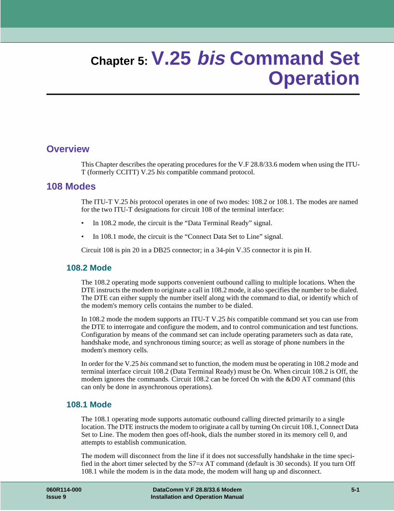
e ITU-
amed
n the dialed. h of
m tions. rate,
the
and f, the (this
e Data nd
eci-
Chapter 5: V.25 bis Command SetOperation
Overview
This Chapter describes the operating procedures for the V.F 28.8/33.6 modem when using thT (formerly CCITT) V.25 bis compatible command protocol.
108 Modes
The ITU-T V.25 bis protocol operates in one of two modes: 108.2 or 108.1. The modes are nfor the two ITU-T designations for circuit 108 of the terminal interface:
• In 108.2 mode, the circuit is the “Data Terminal Ready” signal.
• In 108.1 mode, the circuit is the “Connect Data Set to Line” signal.
Circuit 108 is pin 20 in a DB25 connector; in a 34-pin V.35 connector it is pin H.
108.2 Mode
The 108.2 operating mode supports convenient outbound calling to multiple locations. WheDTE instructs the modem to originate a call in 108.2 mode, it also specifies the number to be The DTE can either supply the number itself along with the command to dial, or identify whicthe modem's memory cells contains the number to be dialed.
In 108.2 mode the modem supports an ITU-T V.25 bis compatible command set you can use frothe DTE to interrogate and configure the modem, and to control communication and test funcConfiguration by means of the command set can include operating parameters such as datahandshake mode, and synchronous timing source; as well as storage of phone numbers in modem's memory cells.
In order for the V.25 bis command set to function, the modem must be operating in 108.2 modeterminal interface circuit 108.2 (Data Terminal Ready) must be On. When circuit 108.2 is Ofmodem ignores the commands. Circuit 108.2 can be forced On with the &D0 AT command can only be done in asynchronous operations).
108.1 Mode
The 108.1 operating mode supports automatic outbound calling directed primarily to a singllocation. The DTE instructs the modem to originate a call by turning On circuit 108.1, ConnectSet to Line. The modem then goes off-hook, dials the number stored in its memory cell 0, aattempts to establish communication.
The modem will disconnect from the line if it does not successfully handshake in the time spfied in the abort timer selected by the S7=x AT command (default is 30 seconds). If you turn Off108.1 while the modem is in the data mode, the modem will hang up and disconnect.
060R114-000 DataComm V.F 28.8/33.6 Modem 5-1Issue 9 Installation and Operation Manual

V.25 bis Command Set Operation Operating Procedures
08.1 ode
8.1
full
odem ial
ate termi-
ls by some
The ITU-T V.25 bis compatible command set is not available when the modem is operating in 1mode. Storage of a telephone number in memory cell 0 must be performed either in 108.2 m(using the PRN command), or by means of AT commands.
Any number can be called in 108.1 mode by dialing manually and then turning On circuit 10when answer tone is heard from the remote modem.
Operating ProceduresRefer to the ITU-T V.25 bis Command Set Communication Operating Procedures below for adescription of the communication procedures for the 108.2 and 108.1 modes.
Refer to Synchronous V.25 bis Interface Specifications below for synchronous dialing protocolformats.
Commanding the ModemAlthough the AT command set is the primary command set for configuring the modem, the mprovides an enhanced ITU-T V.25 bis command protocol that permits you to configure modem dparameters and establish data communications. After configuring the modem using the AT command set, use the %Vn command to switch to the V.25 bis command set.
Table 5-1 summarizes the V.25 bis compatible command set. When entering commands, termineach one with a line feed <LF> control character. The modem sends a response back to thenal for each command. Table 5-2 explains responses to valid commands. Table 5-3 explains responses to invalid commands, and Table 5-4 explains the legal dialing characters. Most terminadisplay the responses to indicate each entered command's result, but responses are ignoredcommunications software that enables a computer to emulate a terminal.
Descriptions of each V.25 bis 108.2 mode command appear on the following pages.
Operating procedures for establishing and terminating data communications are explained following the command descriptions.
Table 5-1 V.25 bis Command Set Summary
Configuration Commands
Name Cmd. Page
AT Command Set PRS AT 5-4
Automatic Answering PRS AA 5-4
Connect Message Inhibit PRS CM 5-4
DTE Data Rate PRS DR 5-5
Handshake Mode PRS HM 5-6
Store Phone Number to Cell PRN 5-4
Synchronous Timing PTM 5-6
Termination Character PRS TR 5-6
Write Option Settings to User Configuration Profile NVW 5-4
Call Requested Number CRN 5-7
Call Requested Stored Telephone Number CRS 5-7
Connect Incoming Call CIC 5-7
Disconnect Incoming Call DIC 5-7
5-2 DataComm V.F 28.8/33.6 Modem 060R114-000Installation and Operation Manual Issue 9

V.25 bis Command Set Operation Commanding the Modem
Table 5-2 Explanation of Valid Responses
Response Description
CFI AB Call failure indication: no carrier, call was aborted (time-out occurred or character was entered at key-board).
CFI BF Call failure indication: telephone number black list (which uses the 10 memory cells) is full. You cannot place any more calls until: a) after a timeout; b) the memory cell is modified; or c) the modem is reset.
CFI CB Call failure indication: remote modem is busy.
CFI DT Call failure indication: dial tone was not detected (dial tone time-out occurred).
CFI DF Call failure indication: telephone number delayed list (which uses the 10 memory cells) is full. Numbers which are redialed continuously without making a connection are added to the delayed list. They are removed from the list: a) after a timeout; b) when a connection is made; c) when the memory cell is modified; or d) when the modem is reset.
CFI UT Call failure indication: unobtainable number tone was detected.
CNX 300 bps connection is established.
CNX 1200 1200 bps connection is established.
CNX 2400 2400 bps connection is established.
CNX 4800 4800 bps connection is established.
CNX 7200 7200 bps connection is established.
CNX 9600 9600 bps connection is established.
CNX 12000 12,000 bps connection is established.
CNX 14400 14,400 bps connection is established.
CNX 16800 16,800 bps connection is established.
CNX 19200 19,200 bps connection is established.
CNX 21600 21,600 bps connection is established.
CNX 24000 24,000 bps connection is established.
CNX 26400 26,400 bps connection is established.
CNX 28800 28,800 bps connection is established.
INC Incoming call was detected. This response is generated only once for each incoming call.
INV See Table 5-3 for responses to commands that the modem does not recognize.
RNGBK Ringback was detected by the originating modem.
VAL Valid command was invoked.
Table 5-3 Explanation of Invalid Responses
Command Invoked Description of INV Response
DIC INC not received.
PRS Non-selectable option in user's country.
060R114-000 DataComm V.F 28.8/33.6 Modem 5-3Issue 9 Installation and Operation Manual

V.25 bis Command Set Operation V.25 bis Configuration Commands
V.25 bis Configuration CommandsConfiguration commands allow you to configure the modem.
NVW Write Option Settings to User Configuration Profile
NVW saves the current settings to a user configuration profile in the modem's non-volatile memory, with the exception of the Terminator Character option (which is set to its factory default, the line feed control-character). This command saves a set of option values that is activated when the modem is powered up.
To invoke this command, type:NVW ; n <LF>
where n is the user configuration profile (0 to 3).
PRN Store Phone Number to Cell
PRN stores a telephone number in one of the modem's ten memory cells. Numbers stored by means of this command can be automatically dialed either by invoking the CRS command in 108.2 mode, or by turning On circuit 108.1 in 108.1 mode (108.1 dialing uses only the number stored in memory cell 0).
To store a number, type:PRN n1 ; n2 <LF>
where n1 is the memory cell (from 0 to 9) in which the number is to be stored, and n2 is the phone number to be stored. n2 may contain any legal dialing characters (0-9 A-D P T # * , < ! & @).
PRS AA Automatic Answering
PRS AA controls the automatic answering function. When you enable automatic answering, you can specify the number of rings the modem will wait before it performs automatic answering. Default is 4 rings.
To enable automatic answering, type:PRS AA ; n <LF>
where n is the number of rings (from 1 to 255) that the modem waits before automatically answering an incoming call.To disable automatic answering, type
PRS AA ; 0 <LF>
PRS AT AT Command Set
PRS AT switches the modem from V.25 bis command set mode to AT command set mode. To return to V.25 bis command set mode, use the AT%Vn command.
To invoke this command, type:PRS AT <LF>
PRS CM Connect Message Inhibit
PRS CM controls the CNX yy connect message responses. The V.F 28.8/33.6 supports both the 1989 and the 1984 recommendations for V.25 bis connection procedures. The 1989 CCITT Blue Book recommends that when the modem transfers from command mode to data mode it should send a connect message of the form CNX yy, where yy identifies the connect speed (96 = 9600 bps, 48 = 4800 bps, 24 = 2400 bps, and 12 = 1200 bps; omitted for 300 bps). The 1984 CCITT Red Book does not include these connect messages. Default is 0 (connect message disabled).
5-4 DataComm V.F 28.8/33.6 Modem 060R114-000Installation and Operation Manual Issue 9

V.25 bis Command Set Operation V.25 bis Configuration Commands
om-
he
To disable the CNX yy connect message responses, type:PRS CM ; 0 <LF>
To enable responses, type:PRS CM ; 1 <LF>
Note: After modifying this option you should save the setting by using the NVW cmand.
PRS DR DTE Data Rate
PRS DR, in conjunction with the hand-shake mode command (PRS HM), controls the DTE speed. There are several configurations to consider:a. An automatic handshake mode (e.g., V.32 bis auto [PRS HM ; 2], V.32 auto
[PRS HM ; 4], V.22 bis only [PRS HM ; 6]) takes precedence over the PRS DR selection, and the modem tries for the highest VF speed common to the two commands.
b. For 1200 bps V.22 operation, select PRS HM ; 7. PRS HM ; 6 is an auto mode, so setting the DTE to 1200 bps (PRS DR ; 3) will not force the connection to 1200 bps.
c. When the modem is optioned for an automatic hand-shake mode and direct V.14 asynchronous mode (AT command \N1), it sends a connect message to the DTE at the selected PRS DR speed. In order to pass data, the user must change the DTE's speed to match the displayed connect speed.
d. When the modem is optioned for speed buffering (AT command \N0) or an error correcting protocol (AT commands \N2 through \N5), the PRS DR command alone selects the DTE speed, and the PRS HM command selects the hand-shake mode.
e. When the modem is optioned for a fixed handshake mode and direct mode (AT command \N1), the PRS DR command not only selects the DTE speed, but also forces the VF speed to match it. If the required VF speed is not available the modem drops the call. (This does not apply to V.22 bis only, which handshakes at the highest VF speed.)
f. When using the modem in direct mode (AT command \N1), if the desired connect speed is known, set the speed to match using the PRS DR command. Set the DTE to the same speed and “AT” the modem so that it will know at what speed to send messages.
Note: The modem must be in the AT command set mode in order to configure t\Nn AT command.
To invoke this command, type:PRS DR ; n <LF>
where n is the DTE rate, as follows:n rate n rate0 Autobaud 11 19,200 bps1 Last connect speed 12 21,600 bps2 300 bps 13 24,000 bps3 1200 bps 14 26,400 bps4 2400 bps 15 28,800 bps5 4800 bps 16 38,400 bps6 7200 bps 17 57,600 bps7 9600 bps 18 76,800 bps8 12,000 bps 19 115,200 bps9 14,400 bps 20 128,000 bps10 16,800 bps
060R114-000 DataComm V.F 28.8/33.6 Modem 5-5Issue 9 Installation and Operation Manual

V.25 bis Command Set Operation V.25 bis Configuration Commands
1), e tic o it
de, to
PRS HM Handshake Mode
PRS HM selects the handshake mode.
Note:
a. When the modem is optioned for an external transmit clock source (PTM ;the modem should be optioned for a fixed - not an automatic - hand-shakmode (e.g., select V.32 bis only [PRS HM ; 3] instead of V.32 bis automa[PRS HM ; 2]). The modem will then handshake only at the speed given tby the DTE.
b. For 1200 bps V.22 operation, select PRS HM ; 7. PRS HM ; 6 is an auto moso setting the DTE to 1200 bps (PRS DR ; 3) will not force the connection1200 bps.
To invoke this command, type:PRS HM ; n <LF>
where n is the handshake mode, as follows:n mode0 auto (28.8 kbps to 300 bps)1 only (28.8 kbps to 9600 bps)2 V.32 bis automatic (14.4 kbps to 300 bps)3 V.32 bis only (14.4 kbps to 4800 bps)4 V.32 automatic (9600 bps to 300 bps)5 V.32 only (9600 bps to 4800 bps)6 V.22 bis only (2400 bps to 1200 bps)7 V.22 only (1200 bps)8 Bell 212 only (1200 bps)9 Bell 103 only (300 bps)10 V.21 only (300 bps)
PRS TR Termination Character
PRS TR selects the ASCII character that represents the command termination character in the asynchronous mode. The command termination character is the character used to enter a command for interpretation by the modem. Select the command termination character that is compatible with your preference and your terminal. Default is 10 or <LF> (line feed).
To select the line feed control-character as the command termination character, type:PRS TR ; 10 <LF>
To select the vertical tabulation control-character, type:PRS TR ; 11 <LF>
To select the form feed control-character, type:PRS TR ; 12 <LF>
PTM Synchronous Timing
PTM selects the clock source when operating in a synchronous data mode.
To select internal clock (supplied by the modem), type:PTM ; 0 <LF>
To select external clock (supplied by the DTE), type:PTM ; 1 <LF>
To select receiver wrap clock (derived from received data), type:PTM ; 2 <LF>
5-6 DataComm V.F 28.8/33.6 Modem 060R114-000Installation and Operation Manual Issue 9

V.25 bis Command Set Operation V.25 bis Communication Commands
V.25 bis Communication CommandsCommunication commands allow you to establish and terminate data communications.
CIC Connect Incoming Call
CIC causes the modem to automatically answer the current incoming call. It temporarily modifies the automatic answering function so that the modem immediately answers the call, ignoring the number of automatic answering rings selected with the PRS AA command. Ten seconds after one incoming call is completed, normal automatic answering is restored.
To invoke this command, type:CIC <LF>
CRN Call Requested Number
CRN causes the modem to dial a telephone number, supplied with the command, to ini-tiate data communication with another modem. If the handshake abort timer (AT command S7=x) times out before the modem detects answer tone, the modem will return on-hook.
To invoke this command, type:CRN n <LF>
where n is the telephone number to be dialed. (The modem recognizes only the characters contained in n that are listed in Table 5-4.) To dial 555-1234, for example, type:
CRN 5551234 <LF>
CRS Call Requested Stored Telephone Number
CRS causes the modem to dial the telephone number stored in a specified modem memory cell. The number to be dialed must have been stored in a memory cell previously by means of the PRN command.
To invoke this command, type:CRS n <LF>
where n is the number (from 0 to 9) of the memory cell that contains the telephone number to be dialed. For example, to dial the number stored in memory cell 5, type:
CRS 5 <LF>
DIC Disconnect Incoming Call
DIC causes the modem to temporarily disable the automatic answering function and ignore an incoming call. Ten seconds after one incoming call is completed, normal automatic answering is restored.
To invoke this command, type:DIC <LF>
060R114-000 DataComm V.F 28.8/33.6 Modem 5-7Issue 9 Installation and Operation Manual

V.25 bis Command Set Operation V.25 bis Communication Commands
Table 5-4 Legal Dialing Characters
Character Description
0 1 2 3 4 5 6 7 8 or 9
Pulse and tone dial digits
# Tone dial character
* Tone dial character
P Causes dialed numerals following P to be dialed using pulses. Used to select pulse dialing for compatibility with your telephone system. Pulse dialing is blocked by some country code configurations.
T Causes dialed alphanumeric characters following T to be dialed using tones. Used to select tone dialing for compatibility with the telephone system you intend to use.
, or < Causes the modem to pause a specified length of time before dialing the next digit of a telephone number (the pause is 2 seconds in length by default and may be changed with the ATS8=x command). Used when the telephone system requires a pause before it can accept the next digit of the telephone number being dialed.
! or & Causes the modem to go on-hook (flash) momentarily. Used to command certain internal telephone systems (PBXs).
@ Causes the modem to wait n seconds for one or more rings followed by five seconds of silence before dialing the next digit of a telephone number (if n seconds expire before a ring is detected, the modem will abort dialing and return to the command mode). Used to dial a telephone system that does not provide dial tone. Silence, rather than dial tone, indicates that the telephone system is ready to accept telephone number dialing. (n = the value selected in the abort timer.)
Ln On dial failure, link to the telephone number stored in cell n (n = 0 to 9).
W or : Causes the modem to wait a specified length of time for dial tone before dialing the next digit of the telephone number. The length of time is specified by the ATS7=x command. If this time expires before dial tone is detected, the modem will abort dialing and return to the command line.
5-8 DataComm V.F 28.8/33.6 Modem 060R114-000Installation and Operation Manual Issue 9

V.25 bis Command Set Operation ITU-T V.25 bis Communication Operating Procedures
.6
ed
gs.
ata e
ring is lls:
ata e
his n; it
ITU-T V.25 bis Communication Operating Procedures
The following paragraphs describe communication operating procedures for the V.F 28.8/33using the ITU-T V.25 bis command set. The descriptions include procedures for originating, answering, and terminating a call in the 108.2 and 108.1 modes.
108.2 Mode Operating Procedures
Originating a Call
To establish communication by originating a call in the 108.2 mode:
1. From the DTE, use the CRN or CRS command to dial the desired telephone number.
2. When communication is established, your terminal displays the CNX response (if enablwith the PRS CM ; 1 command) and you may transfer data.
Automatic Call Answering
To have the modem automatically answer calls and establish communication:
1. Enable automatic answering by typing:
PRS AA ; n <LF>
where n is the number of rings (from 1 to 255) that the modem will wait before it performsautomatic answering. The default is 4.
2. The modem will answer any incoming call automatically after the specified number of rin
3. When communication is established, your terminal will display the CNX response and dtransfer can take place. If communication is not established, your terminal will display thappropriate response and the modem will return to the command mode.
Manual Call Answering
The command PRS AA ; 0 <LF> disables automatic call answering. When automatic answedisabled, use the following procedure to establish communication by manually answering ca
1. When your terminal displays the INC result code to indicate an incoming call, type:
CIC <LF>
2. When communication is established, your terminal will display the CNX response and dtransfer can take place. If communication is not established, your terminal will display thappropriate response and the modem will return to the command mode.
Automatic Call Termination
The modem will automatically terminate a call
a. if terminal interface signal 108.2 (DTR) is turned Off while the modem is in data mode. Tmode of automatic termination functions only when DTR is optioned for normal operatiois disabled if 108.2 is optioned for forced On operation.
060R114-000 DataComm V.F 28.8/33.6 Modem 5-9Issue 9 Installation and Operation Manual

V.25 bis Command Set Operation ITU-T V.25 bis Communication Operating Procedures
the
ing at
5
b. if the handshaking sequence is not completed within the abort time period (selected by S7=x AT command; default is 30 seconds) after originating or answering a call.
c. if a long space is received and long space disconnect has been enabled by the Yn AT command. This mode of automatic termination functions only when the modem is operat300, 1200, or 2400 bps.
108.2 Call Establishment Procedure
The general principle for establishing a call between the DTE and DCE complies with the V.2bis 108.2 mode of operation and is outlined below:
Originating a Call
Answering a Call
DTE DCE
Turn On DTR. Turn On CTS.
Send Command: CRN or CRS. Send VAL response. Dial phone number.
Wait for the connection (or abort the call by turning Off DTR).
Turn Off CTS when answer tone is detected or send CFI response in cases where the call has failed.Turn On DSR and DCD when hand-shake is successful.
Recognize successful connection when DSR comes On. Recognize connected data rate from the CNX message.
Send connect CNX message.
Enter data transfer mode.
Turn On RTS to send data. Turn On CTS in response to RTS.
Turn Off DTR to terminate call. Disconnect from line.Turn Off CTS, DSR, and DCD.Send CFI call abort message.
DTE DCE
Turn On DTR. After detection of an incoming ring, send INC message. When Auto Answer is enabled, modem will answer call after preset number of rings if DTR is On.The CIC command is not required.
Send CIC command to permit answering, or send DIC command to disregard the incoming ring.
Disregard incoming ring if DIC is received. Answer call after the next ring if CIC is received. At next ring, go off-hook.Turn Off CTS.Turn On DSR and DCD when going through handshake successfully.
Recognize successful connection when DSR comes On.
Send connect CNX message.Go into data transfer mode.
Recognize connected data rate from the CNX message.
Turn On RTS to send data. Turn On CTS in response to RTS.
Turn Off DTR to terminate call. Disconnect from line.Turn Off CTS, DSR, and DCD.Send CFI call abort message
5-10 DataComm V.F 28.8/33.6 Modem 060R114-000Installation and Operation Manual Issue 9

V.25 bis Command Set Operation ITU-T V.25 bis Communication Operating Procedures
cell 0.
08.1.
r m the
fer the rcuit
d. The
he
lert
hile
ion by
minal
108.1 Mode Operating Procedures
Originating a Call Automatically
To establish communication by automatically originating a call in the 108.1 mode:
1. Prior to the time of calling a telephone number must be stored in the modem's memory That can be done with either the 108.2 mode PRN command or the AT command &Zn=nnn.
2. To initiate an automatically dialed call in 108.1 mode, turn On terminal interface circuit 1
3. When communication is established with the remote modem, you may transfer data.
Originating a Call Manually
To establish communication by manually originating a call:
1. Lift the telephone handset, listen for a dial tone, and call the remote site.
2. When calling an automatically answered site, turn On terminal interface circuit 108.1 - opress the talk/data switch (D/TK key) on the front panel - when you hear answer tone froremote modem.
3. When calling a manually answered site, ask the attendant who answers the call to transremote modem to data mode. When you hear answer tone, turn On terminal interface ci108.1 - or press the talk/data switch (D/TK key) on the front panel.
4. When communication is established, you may transfer data.
Automatic Call Answering
The modem can answer calls automatically in 108.1 mode if the function has not been disableautomatic answer enable/disable command (in 108.2 mode) is
PRS AA ; n <LF>
where n is the number of rings (from 1 to 255) that the modem will wait before it begins tautomatic answering process.
PRS AA ; 0 <LF> disables automatic answering. The default is 4.
The following sequence of events takes place when them modem senses an incoming call:
1. After the specified number of rings, the modem turns On circuit 125 (Call Indicator) to athe DTE that an incoming call is trying to make a connection.
2. If the DTE is prepared to accept the connection it responds by turning On circuit 108.1. WCall Indicator is On, circuit 108.1 acts as the command to perform automatic answering.
3. The modem then goes off-hook, performs handshaking, and - when that is successfully completed - begins data transfer with the remote modem.
Manual Call Answering
When automatic answering is disabled, use the following procedure to establish communicatmanually answering calls:
1. When the telephone rings, lift the handset.
2. When the remote site attendant asks you to place the modem in data mode, turn On terinterface 108.1 - or press the talk/data switch (D/TK key) on the front panel.
060R114-000 DataComm V.F 28.8/33.6 Modem 5-11Issue 9 Installation and Operation Manual

V.25 bis Command Set Operation V.25 bis 108.2 Mode Interface Specifications
witch.
us. The ponses onse
us
). The
3. Hang up the handset. You may now commence data communications.
Terminating a Call
To terminate communication, turn Off terminal interface circuit 108.1 or press the talk/data s
V.25 bis 108.2 Mode Interface Specifications
Physical connections between a DTE and a DCE may be either synchronous or asynchronoITU-T V.25 bis 108.2 mode recommendations describe the exchange of commands and resbetween the units using both types of operation. The V.F 28.8/33.6 supports command/respexchange in either mode.
The following paragraphs describe the functional characteristics of the V.25 bis synchronous and asynchronous interfaces, as used in the V.F 28.8/33.6 modem.
Interface Connections
Synchronous Format Selection
The V.F 28.8/33.6 supports both the bit-oriented and the byte-oriented modes of synchronooperation.
Synchronous Bit-Oriented Operation
The modem uses the HDLC format in the bit-oriented synchronous mode (%V2 AT commandstructure of each message in this format is shown below:
From DCE to DTE 104 RXD
106 CTS
107 DSR
125 Call Indicator/Ring Detector
114 TX Timing (synchronous only)
115 RX Timing (synchronous only)
From DTE to DCE: 103 TXD
105 RTS
108.2 DTR
113 TX Timing (synchronous only)
← Time
F FCS Message C A F
F = Idle Flag (01111110)
FCS = Frame Check Sequence (CRC-ITU-T, x16+x12+x5+1)
Message = Command/Response (7-bit ASCII data and 1 odd parity)
C = Control (00010011*)
A = Address (11111111*)
*The modem will not recognize the C or A fields unless verified as shown above.
5-12 DataComm V.F 28.8/33.6 Modem 060R114-000Installation and Operation Manual Issue 9

V.25 bis Command Set Operation V.25 bis 108.2 Mode Interface Specifications
T
nous
own
s. In men-
Synchronous Byte-Oriented Operation
The modem uses the BISYNC (BSC) format in the byte-oriented synchronous mode (%V3 Acommand). The structure of each message in this format is shown below:
Data Rate
The V.F 28.8/33.6 does not support 300 bps in the synchronous mode. Also, in the synchromode, the modem will not hand-shake with an incoming call at 300 bps FSK.
Asynchronous Format
The structure of each message in the asynchronous mode (%V1 AT command) format is shbelow:
← Time
BCC ETX Message STX SYN SYN
BCC = LRC Block Check Character for ASCII
ETX = ASCII ETX Character (10000011)
Message = Command/Response (7-bit ASCII data and 1 odd parity)
STX = ASCII STX Character (00000010)
SYN = ASCII SYN Character (00010110)
Note BCC is always transmitted in the modem's responses, but optionally included in the DTE commandthis way, the modem conforms to BSC conventions without deviating from the ITU-T V.25 bis Recomdations.
← Time
OFF LF Message OFF
OFF = Interface idle
Message = Command/Response (10-bit characters: 1 start, 7-bit ASCII data, 1 even parity, 1 stop)
LF = ASCII Line Feed Character (00001010)
060R114-000 DataComm V.F 28.8/33.6 Modem 5-13Issue 9 Installation and Operation Manual

V.25 bis Command Set Operation V.25 bis 108.2 Mode Interface Specifications
idle front
Modem Test Modes
When optioned to operate in the synchronous V.25 bis mode, the V.F 28.8/33.6 supports the following test modes that can be initiated from the Front Panel:
• Analog Loopback
• Analog Loopback with Self-Test
• Digital Loopback
• Remote Digital Loopback
• Remote Digital Loopback with Self-Test
• End-to-End Self-Test
All tests may be terminated from the front panel switches, and the modem returns to off-linecommand state when DTR goes from On to Off. Pending tests can be cleared only from thepanel.
5-14 DataComm V.F 28.8/33.6 Modem 060R114-000Installation and Operation Manual Issue 9

isolate
with
r will
Chapter 6: Tests
Overview
This chapter describes tests that you can perform to isolate a trouble condition. The tests cana problem to the data connection, data set operation, or the DTE interface level. Refer to Figure 6-1 for a sequence of tests for fault isolation.
Figure 6-1 Fault Isolation Sequence
Note a. On-line tests, which involve data transmitted from one modem to another, can be performedthe modems operating in either synchronous mode or direct (N1) asynchronous mode.
b. Once a modem is in Slave RDL, it will ignore all requests other than AL.
c. If an MRDL request does not get a response from the Slave modem at 2400 bps, the Mastedrop the line.
PASS OR FAIL
?
PASSFAIL
PASS OR FAIL
?
PASSFAIL
PASS OR FAIL
?
PASSFAIL
PASS OR FAIL
?
PASSFAIL
PASS OR FAIL
?
PASSFAIL
PERFORM ANALOG LOOPBACK
WITH SELF-TEST
REMOTE MODEM PROBLEM
START
PERFORM ANALOG LOOPBACK
COMMUNICATION LINE PROBLEM
LOCAL MODEM PROBLEM
LOCAL TERMINAL OR LOCAL TERMINAL-MODEM CONNECTION PROBLEM
PERFORM REMOTE DIGITAL LOOPBACK WITH
SELF-TEST AT REMOTE MODEM
PERFORM LOCAL DIGITAL LOOPBACK
WITH SELF-TEST
PERFORM REMOTE DIGITAL LOOPBACK
WITH SELF-TEST
REMOTE TERMINAL OR REMOTE TERMINAL-MODEM
CONNECTION PROBLEMCOMMUNICATION
LINE PROBLEM
060R114-000 DataComm V.F 28.8/33.6 Modem 6-1Issue 9 Installation and Operation Manual

Tests Analog Loopback (ANALOOP)
e tor trolled
e a t match
E rate. orted
Analog Loopback (ANALOOP)The Analog Loopback (AL) test mode, illustrated below, is provided to isolate problems in thmodem operation and the DTE interface. Specifically, AL tests modem modulator/demodulaoperation, DTE receive/transmit operation, and DTE interface operation. The test can be confrom the front panel or by AT commands.
.
Note When the modem is used in \N0, \N2, \N3, \N4 or \N5 modes with a fixed DTE speed, it will not issuCONNECT message. When the modem is used in \N1 mode, since the AL handshake speed may nothe DTE speed selected, the modem will issue a CONNECT _ _ _ _ message at the last known DTIf the DTE rate and handshake rate differ, the user can change the DTE speed to match the rate repby the CONNECT message.
Table 6-1 Analog Loopback
Step Front Panel AT Command Mode
1. To start the test, press AL. To start the test, type: AT&T1 (enter). If modem responds with an error message, type: AT%T0 (enter), which resets the test mode, then re-enter the command.
2. The modem flashes the TM LED and displays the test name (LL) while it is setting up the test, then lights the TM LED and decimal point three while the test is running.
The modem flashes the TM LED while it is setting up the test, then lights the TM LED and decimal point three while the test is running.
3. Enter test data at the DTE. Compare the data that was entered at the DTE with the data that is looped back and displayed by the DTE. If errors occur frequently, a problem may exist in the modem, the DTE, or the DTE-to-modem connection. Refer to the fault-isolation diagram to isolate the problem.
4. To end the test, press AL, RDL or DL. To end the test, type the escape sequence (+++) and, after the modem is in the command mode, type: AT&T0 (enter).
Modem transmitter
Modem receiver
Send data
Received dataDTECommunications line
Local loopback
V.F. 28.8 TR SD RD MR RS CS CO GD TM ALM OH
AL ST RDL DL SEL D/TK
ADV
1. To start the test, press AL.2. TM flashes and the test name (LL) appears on the LCD while it is setting up the test, then TM lights and decimal point three appears while the test is running.
3. Enter test data on DTE. Compare this data with the datathat was looped back and displayed on the DTE.4. To end the test, press AL.
6-2 DataComm V.F 28.8/33.6 Modem 060R114-000Installation and Operation Manual Issue 9

Tests Analog Loopback with Self-Test
elf-tern is the
test pro-s test is
Analog Loopback with Self-TestAnalog Loopback may be combined with Self-Test, as illustrated below. Upon initiation of STest, a pattern is generated by the transmitter and sent to the receiver for analysis. The patmade up of alternate ones and zeros for speeds of 1200 and 2400 bps. For all other speedsmodem generates a 511 test pattern. The number of errors is displayed on the screen. Thisvides a means for the customer to determine whether the problem is in the local data set.Thinot operational when the modems are passing data at 300 bps.
Table 6-2 Analog Loopback with Self-Test
Step Front Panel AT Command Mode
1. To start the test press AL, then press ST. To start the test, type: AT&T8 (enter). If modem responds with an error message, type: AT%T0 (enter), which resets the test mode, then re-enter the command.
2. The modem flashes the TM LED and displays the test names (LL and ST) while it is setting up the test, then lights the TM LED and dis-plays four digits of the error count (0000 to 9999) while the test is running. It indicates larger numbers by lighting decimal point one and displaying the four least significant digits of the actual count (for example, the actual error count is 12345, but the modem displays 2.345).
The modem flashes the TM LED while it is setting up the test, then lights the TM LED while the test is running. When the test is terminated, the screen displays a four-digit number corresponding to the number of errors detected during the test, followed by the OK message. Any number greater than 0 indicates the modem has failed the test.
3. If the timer, S-Register 18, is set to a value between 1 and 60, the test ends automatically after that value (in 10-second increments) is reached. The factory default for S-Register 18 is 000, meaning that the test will continue indefinitely.
4. To end the test, press AL, RDL or DL. To end the test, type the escape sequence (+++) and, after the modem is in the command mode, type: AT&T0 (enter).
Modem transmit-
Modem
Send data
Received DTECommunications line
Local loopback
Self-test pattern generator
Self-test pattern receiver
V.F. 28.8 TR SD RD MR RS CS CO GD TM ALM OH
AL ST RDL DL SEL D/TK
ADV
1. To start the test press AL, then press ST.2. TM flashes and the LCD displays the test names (LL and ST) while it is setting up the test,then TM lights and the LCD displays four digits of the error count (0000 to 9999) while the testis running.
3. When the timer (S-register 18) times out, the test ends.4. To end the test, press AL, RDL or DL.
060R114-000 DataComm V.F 28.8/33.6 Modem 6-3Issue 9 Installation and Operation Manual

Tests Digital Loopback
front ed. In
te unit the
Digital LoopbackThe modem can be commanded to enter digital loopback, illustrated below, by means of thepanel or AT commands. This loopback is used while a call to the distant modem is establishdigital loopback, the local received data is coupled to the transmitter input, so that the remocan perform a loopback test without commanding remote loopback. In asynchronous mode clocks will be clamped at the EIA interface.
Table 6-3 Digital Loopback
Step Front Panel AT Command Mode
1. Establish data communications with a remote modem.
2. To start the test, press DL. To start the test, type the escape sequence (+++) and, after the modem is in the command mode, type: AT&T3 (enter). If modem responds with an error message, type: AT%T0 (enter), which resets the test mode, then re-enter the command.
3. The modem flashes the TM LED and displays the test name (DL) while it is set-ting up the test, then lights the TM LED and decimal point one while the test is running.
The modem flashes the TM LED while it is set-ting up the test, then lights the TM LED and decimal point one while the test is running.
4. Direct the remote attendant to enter data at the remote DTE, then compare it with the data that is looped back and displayed by the DTE. If errors occur frequently, a problem may exist in the local or remote modems, the remote DTE, the remote DTE-to-modem connection, or the communication line. Refer to the fault isolation diagram to isolate the problem.
5. To end the test, press AL, RDL or DL. To end the test, type: AT&T0 (enter) then type ATO (enter) to go back on line.
Modemtransmit-DTE
Digital loop-
Modemreceiver
Communications
V.F. 28.8 TR SD RD MR RS CS CO GD TM ALM OH
AL ST RDL DL SEL D/TK
ADV
1. Establish data communications with the remote modem.2. To start the test. press DL.3. TM flashes and the LCD displays the test name (DL) while it is setting up the test, thenTM lights and decimal point one is displayed while the test is running.
4. Ask the remote attendant to enter data at the remote DTE, then compare it with the data that is looped back and displayed by the DTE.5. To end the test, press DL.
6-4 DataComm V.F 28.8/33.6 Modem 060R114-000Installation and Operation Manual Issue 9

Tests Remote Digital Loopback
ded e itter
al
and to ill
Remote Digital LoopbackRemote Digital Loopback, illustrated below, is controlled at the local end. It can be commanfrom the front panel, or with AT commands, or by the DTE's EIA pin 21. The loopback can bcommanded only after a call is established and both ends are in data mode. In this loop, thedemodulator's descrambled received data at the remote end is coupled to the remote transminput for transmission back to the local end.
This test is not operational when the modems are passing data at 300 bps.
Note This test cannot be performed if the remote modem is commanded to ignore a remote digitloopback command.
If the modems are operating at V.22 bis speeds and the local modem issues the RDL comma remote unit configured to ignore the remote loop-back command the resulting condition wcause the local modem to drop the connection.
Table 6-4 Remote Digital Loopback
Step Front Panel AT Command Mode
1. Establish data communications with a remote modem.
2. Check with the remote attendant that the remote modem will accept Remote Digital Loopback commands.
Modemtransmit-
DTE
Communica-tions
DTE
LOCAL REMOTE
Modemreceiver
Modemreceiver
Modemtransmit-
For the remote loopback test, the remote DTE or terminal is disconnected.
Send
data
Received
Remote loopback
V.F. 28.8 TR SD RD MR RS CS CO GD TM ALM OH
AL ST RDL DL SEL D/TK
ADV
1. Establish data communications with the remote modem.2. Check with the remote attendant that the remote modem will acceptRemote Digital Loopback commands.3. To start the test, press RDL.
4. TM flashes and the LCD displays the test name (RL) while it is setting up the test,then TM lights, and decimal point two appears on the LCD while the test is running.5. Enter data at the local DTE. Compare data that was entered at the DTE with the datathat is looped back and displayed by the DTE.6. To end the test, press AL, RDL or DL.
V.F. 28.8 TR SD RD MR RS CS CO GD TM ALM OH
AL ST RDL DL SEL D/TK
ADV
LOCAL
REMOTE
060R114-000 DataComm V.F 28.8/33.6 Modem 6-5Issue 9 Installation and Operation Manual

Tests Remote Digital Loopback
connect
3. To start the test, press RDL. To start the test, type the escape sequence (+++) and, after the modem is in the com-mand mode, type: AT&T6 (enter). If modem responds with an error message, type: AT%T0 (enter), which resets the test mode, then re-enter the command.
4. The modem flashes the TM LED and displays the test name (RL) while it is set-ting up the test, then lights the TM LED and decimal point two while the test is running. (If the remote modem initiated the test, the local modem lights decimal points three and four while the test is running.)
The modem flashes the TM LED while it is set-ting up the test, then lights the TM LED and decimal point two while the test is running. (If the remote modem initiated the test, the local modem lights decimal points three and four while the test is running.)
5. Enter data at the local DTE. Compare data that was entered at the DTE with the data that is looped back and displayed by the DTE. If errors occur frequently, a problem may exist in the local or remote modems, local DTE, local DTE-to-modem connection, or the communication line. Refer to the fault-isolation diagram to isolate the problem.
6. To end the test, press AL, RDL, or DL. To end the test, type the escape sequence (+++) and, after the modem is in the command mode, type: AT&T0 (enter) then type ATO (enter) to go back on line.
Note: Any attempt to terminate the test at the remote modem by using the AT&T0 command will cause the modem to disfrom the line.
Note: CTS at the remote modem will drop low during the test.
Table 6-4 Remote Digital Loopback (Continued)
Step Front Panel AT Command Mode
6-6 DataComm V.F 28.8/33.6 Modem 060R114-000Installation and Operation Manual Issue 9

Tests Remote Digital Loopback with Self-Test
n be after to
iver, to the speeds mber of
com-
Remote Digital Loopback with Self-TestRemote Digital Loopback with Self-Test, illustrated below, is controlled at the local end. It cacommanded from the front panel or with AT commands. This command can only be enteredthe call is established and both ends are in the data mode. The test causes the local modemgenerate a pattern that is transmitted across the telephone line to the remote modem's recelooped through to the remote modem's transmitter, and sent back across the telephone linelocal modem's receiver for analysis. The pattern is made up of alternate ones and zeros forof 1200 and 2400 bps. For all other speeds the modem generates a 511 test pattern. The nuerrors is displayed on the screen. This test checks both modems and the telephone line.
This test is not operational when the modems are passing data at 300 bps.
Note This test cannot be performed if the remote modem is configured to ignore a remote digital loopbackmand.
Table 6-5 Remote Digital Loopback with Self-Test
Step Front Panel AT Command Mode
1. Establish data communications with a remote modem.
2. Check with the remote attendant that the remote modem will accept Remote Digital Loopback commands.
Modemtransmit-DTE
Communica-tions
Remote loop-
DTE
LOCAL
REMOTE
Modemreceiver
Modemreceiver
Modemtransmit-
Self-test pattern
Self-test pattern gen-
For remote loopback, the local DTE or terminal is dis-
V.F. 28.8 TR SD RD MR RS CS CO GD TM ALM OH
AL ST RDL DL SEL D/TK
ADV
1. Establish data communications with the remote modem.2. Check with the remote attendant that the modem will accept Remote Digital Loopback commands.3. To start the test, press RDL, then press ST.4. TM flashes and the LCD displays the names (RL and ST) while it is setting up up the test, TM lights and the LCD displays four digits of the error count (0000 to 9999) while the test is running.
5. When the timer (S-Register 18) times out, the test expires.6. To end the test, press AL, RDL or DL.
LOCAL
V.F. 28.8 TR SD RD MR RS CS CO GD TM ALM OH
AL ST RDL DL SEL D/TK
ADV
REMOTE
060R114-000 DataComm V.F 28.8/33.6 Modem 6-7Issue 9 Installation and Operation Manual

Tests Remote Digital Loopback with Self-Test
3. To start the test press RDL, then press ST. To start the test, type the escape sequence (+++) and, after the modem is in command mode, type: AT&T7 (enter). If modem responds with an error message, type: AT%T0 (enter), which resets the test mode, then re-enter the command.
4. The modem flashes the TM LED and displays the test names (RL and ST) while it is setting up the test, then lights the TM LED and dis-plays four digits of the error count (0000 to 9999) while the test is running. It indicates larger numbers by lighting decimal point one and displaying the four least significant digits of the actual count (for example, the actual er-ror count is 12345, but the modem displays 2.345).
The modem flashes the TM LED while it is setting up the test, then lights the TM LED while the test is running. When the test is terminated, the screen displays a four-digit number corresponding to the number of errors detected during the test, followed by the OK message. Any number greater than 0 indicates the modem has failed the test.
5. If the timer, S-Register 18, is set to a value between 1 and 60, the test ends automatically after that value (in 10-second increments) is reached. The factory default for S-Register 18 is 000, meaning that the test will continue indefinitely.
6. To end the test, press AL, RDL, or DL. To go back on line, type ATO.
Table 6-5 Remote Digital Loopback with Self-Test
Step Front Panel AT Command Mode
6-8 DataComm V.F 28.8/33.6 Modem 060R114-000Installation and Operation Manual Issue 9

Tests End-to-End Self-Test
em. It e h modem checks 400 bps. d is ations
End-to-End Self-TestEnd-to-End Self Test, illustrated below, requires operators at both the local and remote modcan be commanded from the front panels or with AT commands. The commands can only bentered after the call is established and both ends are in the data mode. The test causes eacto generate a pattern and to transmit it to the other modem. The modem receiving the patternit for errors. The patterns are made up of alternate ones and zeros for speeds of 1200 and 2For all other speeds the modems generate a 511 test pattern. The number of errors receivedisplayed on the screen. This test checks the operation of both modems and the communicline.
This test is not operational when the modems are passing data at 300 bps.
Table 6-6 End-to-Tend Self-Test
Step Front Panel AT Command Mode
1. To start the test press ST. To start the test, at each modem type: AT&T9 (enter). If modem responds with an error message, type: AT%T0 (enter), which resets the test mode, then re-enter the command.
2. The modem flashes the TM LED and displays the test name (ST) while it is setting up the test, then lights the TM LED and displays four digits of the error count (0000 to 9999) while the test is running. It in-dicates larger numbers by lighting decimal point one and displaying the four least significant digits of the actual count (for example, the actual error count is 12345, but the modem displays 2.345).
The modem flashes the TM LED while it is setting up the test, then lights the TM LED while the test is running. When the test is terminated, the screen displays a four-digit number corresponding to the number of errors detected during the test, followed by the OK message. Any number greater than 0 indi-cates the modem has failed the test.
Modemtransmit-
DTE
Communica-tions
DTE
LOCAL REMOTE
Modemreceiver
Modemreceiver
Modemtransmit-
Self-test pattern
Self-test pattern gen-
For self-test (end-to-end self-test), both the local and remote DTEs or terminals are disconnected from their modems.
Self-test pattern genera-
Self-test pattern
V.F. 28.8 TR SD RD MR RS CS CO GD TM ALM OH
AL ST RDL DL SEL D/TK
ADV
1. To start the test, press ST.2. TM flashes and the LCD displays the test name (ST) while it is setting up the test,then TM lights and the LCD displays four digits of the error count (0000 to 9999) whilethe test is running.
3. When the timer (S-Register 18) times out, the test expires.4. To end the test, press AL, RDL or DL.
060R114-000 DataComm V.F 28.8/33.6 Modem 6-9Issue 9 Installation and Operation Manual

Tests RDLB Requests
ote ch re-
RDLB RequestsYour modem is factory set to acknowledge a remote modem's request to participate in a remdigital loopback test initiated from the remote location. If you do not want to acknowledge suquests, enter AT&T5&W.
If you later decide to acknowledge such requests, enter AT&T4&W.
3. If the timer, S-Register 18, is set to a value between 1 and 60, the test ends automatically after that value (in 10-second increments) is reached. The factory default for S-Register 18 is 000, meaning that the test will continue indefinitely.
4. To end the test, press AL, RDL, or DL. To end the test, type the escape sequence (+++) at each modem and, after the modem is in the command mode, type: AT&T0 (enter).
Table 6-6 End-to-Tend Self-Test (Continued)
Step Front Panel AT Command Mode
6-10 DataComm V.F 28.8/33.6 Modem 060R114-000Installation and Operation Manual Issue 9

Appendix A: Technical Specifications
Item Specification
VF Data Rate:
33.6 kbps (ITU-T V.34)) Synchronous/asynchronous
31.2 kbps (ITU-T V.34) Synchronous/asynchronous
28.8 kbps (ITU-T V.34)) Synchronous/asynchronous
26.4 kbps (ITU-T V.34) Synchronous/asynchronous
24.0 kbps (ITU-T V.34) Synchronous/asynchronous
21.6 kbps (ITU-T V.34) Synchronous/asynchronous
19.2 kbps (ITU-T V.34) Synchronous/asynchronous
16.8 kbps (ITU-T V.34) Synchronous/asynchronous
14.4 kbps (ITU-T V.34 or V.32 bis) Synchronous/asynchronous
12.0 kbps (ITU-T V.34 or V.32 bis) Synchronous/asynchronous
9600 bps (ITU-T V.34, V.32 bis, or V.32) Synchronous/asynchronous
7200 bps (ITU-T V.34 or V.32 bis) Synchronous/asynchronous
4800 bps (ITU-T V.34, V.32 bis, or V.32) Synchronous/asynchronous
2400 bps (ITU-T V.34 or V.32 bis) Synchronous/asynchronous
1200 bps (ITU-T V.22 or Bell 212A) Synchronous/asynchronous
300 bps (ITU-T V.21) Asynchronous only
300 bps (Bell 103) Asynchronous only
Data Format:
Bit synchronous
Bit asynchronous Selectable 8, 9, 10, or 11 bits per character
Transmit Clock Internal, External, or Receive Wrap
Compatibility ITU-T V.34, V.32 bis, V.32, V.22 bis, V.22, V.21, Bell 212A, and Bell 103
Operating Mode:
Switched network Two-wire full duplex
Private line Two-wire or four-wire
060R114-000 GDC DataComm V.F 28.8/33.6 Modem A-1Issue 9 Installation and Operation Manual

Technical Specifications
nsmit-
Modulation:
2400 bps to 33.6 kbps As specified by ITU-T V.34
14.4 kbps 128-level TCM/2400 Baud ±0.01%
12.0 kbps 64-level TCM/2400 Baud ±0.01%
9600 bps 32-level TCM/2400 Baud ±0.01%
9600 bps 16-level QAM/2400 Baud ±0.01%
7200 bps 16-level TCM/2400 Baud ±0.01%
4800 bps 4-level QAM/2400 Baud ±0.01%
2400 bps 16-level QAM/600 Baud ±0.01%
1200 bps 4-level PSK/600 Baud ±0.01%
0-300 bps FSK 0-300 Baud ±0.01%
Answer Tone:
ITU-T V.32 bis, V.32, V.22 bis, V.22 and V.21 modes 2100 Hz ±3 Hz
Bell 212A and 103 modes 2225 Hz ±3 H
ITU-T V.34 As specified by ITU-T
Transmit Carrier
ITU-T V.32 bis As specified by ITU-T
ITU-T V.32 As specified by ITU-T
ITU-T V.34 As specified by ITU-T
Originate Mode 1200 Hz ±0.5 Hz
Answer Mode 2400 Hz ±1 Hz
ITU-T V.21
Originate Mode Mark Space
1180 Hz ±12 Hz 980 Hz ±12 Hz
Answer Mode Mark Space
1850 ±12 Hz 1650 ±12 Hz
Bell 103
Originate Mode Mark Space
1270 Hz ±12 Hz 1070 Hz ±12 Hz
Answer Mode Mark Space
2225 Hz ±12 Hz 2025 Hz ±12 Hz
Output Level
Permissive -9 dBm maximum or per country requirements.
Programmable -6 to -12 dBm (U.S. Only)
Note: Receiver performance in ITU-T V.34, V.32 bis and V.32 modes may be degraded when trating above -6 dBm.
Item Specification
A-2 GDC DataComm V.F 28.8/33.6 Modem 060R114-000Installation and Operation Manual Issue 9

Technical Specifications
ing
Receive Carrier
ITU-T V.32 bis As specified by ITU-T
ITU-T V.32 As specified by ITU-T
ITU-T V.34 As specified by ITU-T
Note: ITU-T V.34/V.32 bis being echo canceling protocols, use signal quality as criteria for maintainconnection. They also provide for self-training detection to force disconnect.
Originate Mode 2400 Hz ±7 Hz
Answer Mode 1200 Hz ±7 Hz
ITU-T V.21
Originate Mode Mark Space
1850 ±12 Hz 1650 ±12 Hz
Answer Mode Mark Space
1180 Hz ±12 Hz 1650 Hz ±12 Hz
Bell 103
Originate Mode Mark Space
2225 Hz ±12 Hz 2025 Hz ±12 Hz
Answer Mode Mark Space
1270 Hz ±12 Hz 1070 Hz ±12 Hz
Receive Level
Switched Network -6 to -43 dBm
Two-wire Private Line -6 to -33 dBm
Four-wire Private Line 0 to -26 dBm
Carrier Detect (Level for ITU-T V.22 bis, V.22, V.21, 212, 103) in Switched Network
Acquisition Release-43 dBm -48 dBm
Hysteresis 2 dBm minimum
DTE Interface
Standard EIA/TIA-232-E (ITU-T V.24/V.28/ISO 2110)
Optional EIA/TIA-530-A (ITU-T V.10/V.11/V.24/ISO 2110 Amendment 1)V.35 (ITU-T V.24/V.28/V.35/ISO 2593)V.36 (requires a special optional cable)
Line Requirements
Switched Network Two-wire
Private Line Two-wire or four-wire
Line Connection
Switched Network 8-position modular jack (US RJ45)
Phone 6-position modular jack (US RJ11)
Private Line 8-position modular jack (US RJ45)
Item Specification
060R114-000 GDC DataComm V.F 28.8/33.6 Modem A-3Issue 9 Installation and Operation Manual

Technical Specifications
Line Impedance 600 ohms or 900 ohms
Line Equalization Automatic Adaptive
Connection Options One second Line Break Holdover in four-wire private line mode only.Loss of Carrier in ITU-T V.22 bis and lower.Loop Current Disconnect.
Phone Types 500/503 (rotary dial), 2500/2503 (DTMF dial), and no phone
Dialing Pulse and Tone
DTMF Output Level
USA Per Part 68
International per country requirements
Pulse Dial Ratio
USA Make/Break: 39/61%
International per country requirements
Ring Cadence
USA On 2 seconds; Off 4 seconds
International per country requirements
DC Loop Current
USA 20-80 milliamps
International per country requirements
Call Progress Monitor BUSY
CONNECT (rate) (see ITU-T V.42 options for delay)
CONNECT (see ITU-T V.42 options for delay)
NO ANSWER
NO CARRIER
NO DIALTONE
OK (character abort)
RING
RINGING
UNOBTAINABLE NUMBER
Power Consumption 7 card-edge watts dc maximum
DC Voltage (Typical)
+5V +5V ±5% at 1A
+12V +12V ±5% at 0.2A
-12V -12V ±5% at 0.2A
Dimensions (Printed circuit board)
Height 22.2 mm (7/8 in)
Width 248 mm (9 3/4 in)
Depth 273 mm (10 3/4 in)
Item Specification
A-4 GDC DataComm V.F 28.8/33.6 Modem 060R114-000Installation and Operation Manual Issue 9

Technical Specifications
Temperature
Operating 0 to 50×C (32× to 122×F)
Non-operating -40 to 70×C (-40× to 158×F)
Humidity, operating Up to 95 % humidity (non-condensing)
Altitude, operating 0 m to 3,047 m (0 to 10,000 ft)
Item Specification
060R114-000 GDC DataComm V.F 28.8/33.6 Modem A-5Issue 9 Installation and Operation Manual

Technical Specifications
A-6 GDC DataComm V.F 28.8/33.6 Modem 060R114-000Installation and Operation Manual Issue 9

Appendix B: Business Equipment Interface(TIA/EIA-232-F, ITU-T V.24/V.28/ISO 2110)
Pin No.
Circuit
Name Direction Function232-F V.24
Description
2 BA 103 SD To DCE Transmitted Data
Data signals originated by the DTE - to be transmitted to a remote data station via a data channel, or to be passed to the DCE for maintenance test purposes under control of the DTE - are transferred to the DCE on this circuit.
3 BB 104 RD From DCE Received Data
Data signals generated by the DCE - in response to data channel line signals received from a remote data station, or in response to DTE maintenance test signals - are transferred to the DTE on this circuit.
4 CA 105 RTS To DCE Request to Send
Signals on this circuit control the data transmit function of the DCE. The On condition causes the DCE to assume the data channel transmit mode. The Off condition causes the DCE to assume the data channel non-transmit mode when all data transferred on circuit 103 has been transmitted.
5 CB 106 CTS From DCE Clear to Send
Signals on this circuit indicate whether the DCE is ready to transfer data. The On condition indicates that the signal converter or similar equipment is connected to the line and that the DCE is ready to initiate transfer of data. The Off condition indicates that the DCE is not ready to transfer data.
6 CC 107 DSR From DCE Data Set Ready
Signals on this circuit indicate whether the DCE is ready to operate. The On condition indicates that the signal converter or similar equipment is connected to the line and that the DCE is ready to exchange further control signals with the DTE to initiate transfer of data. The Off condition indicates that the DCE is not ready to operate.
7 AB 102 SIG GND Signal Ground
This pin is the signal ground reference for the V.24 interface circuits.
8 CF 109 CO/DCD From DCE Data Channel Receive Line Signal Detect
Signals on this circuit indicate whether the receive data channel line signal is within appropriate limits, as specified in the relevant recommendation for DCE. The On condition indicates that the received signal is within appropriate limits. The Off condition indicates that the received signal is not within the appropriate limits.
15 DB 114 SC From DCE Transmit Clock DCE Source
Signals on this circuit are used to provide the data terminal equipment with signal element timing information. The data terminal equipment shall provide a data signal on the Transmit Data line in which the transitions between signal elements nominally occur at the time of the Off-to-On transitions of the signal on the DB circuit.
17 DD 115 RC From DCE Received Clock
Signals on this circuit are used to provide the data terminal equipment with received signal element timing information. The On-to-Off transition shall nominally indicate the center of each signal element on the BB (Received Data) circuit.
060R114-000 GDC DataComm V.F 28.8/33.6 Modem B-1Issue 9 Installation and Operation Manual
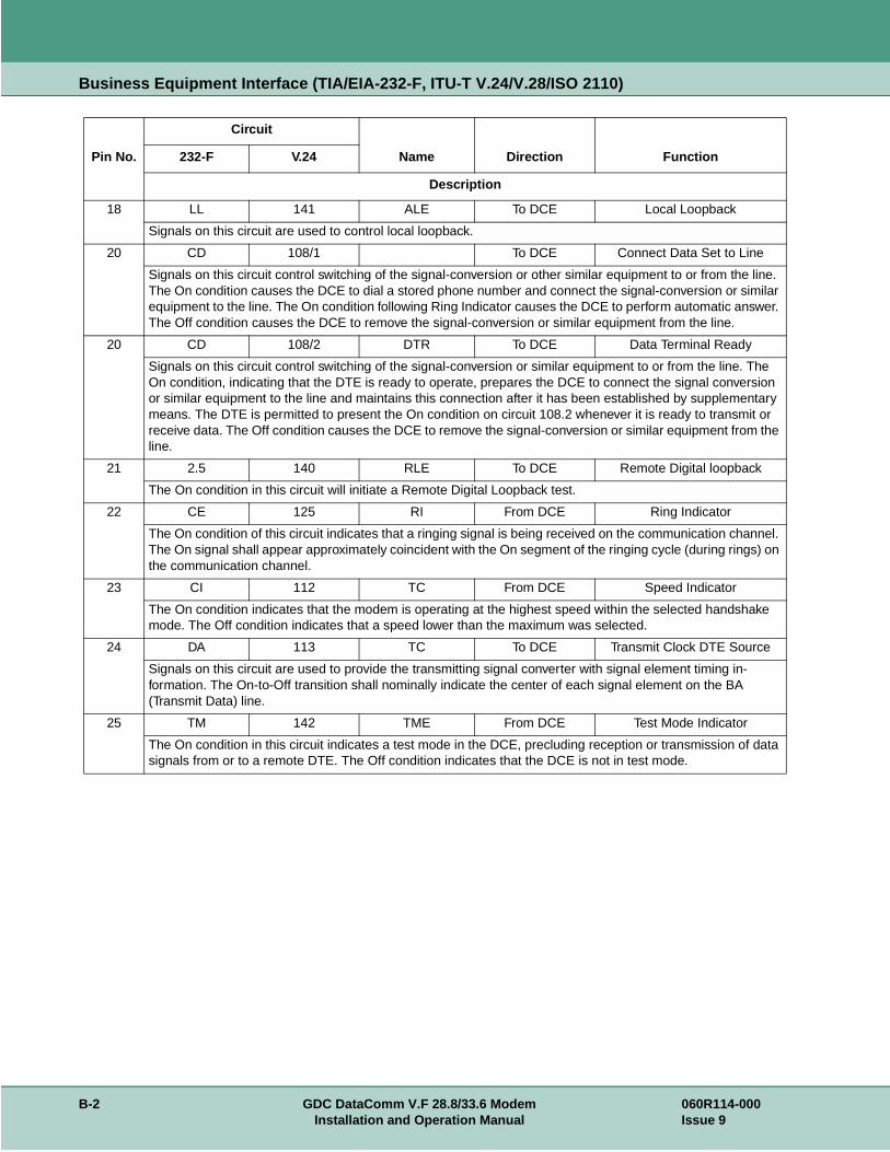
Business Equipment Interface (TIA/EIA-232-F, ITU-T V.24/V.28/ISO 2110)
18 LL 141 ALE To DCE Local Loopback
Signals on this circuit are used to control local loopback.
20 CD 108/1 To DCE Connect Data Set to Line
Signals on this circuit control switching of the signal-conversion or other similar equipment to or from the line. The On condition causes the DCE to dial a stored phone number and connect the signal-conversion or similar equipment to the line. The On condition following Ring Indicator causes the DCE to perform automatic answer. The Off condition causes the DCE to remove the signal-conversion or similar equipment from the line.
20 CD 108/2 DTR To DCE Data Terminal Ready
Signals on this circuit control switching of the signal-conversion or similar equipment to or from the line. The On condition, indicating that the DTE is ready to operate, prepares the DCE to connect the signal conversion or similar equipment to the line and maintains this connection after it has been established by supplementary means. The DTE is permitted to present the On condition on circuit 108.2 whenever it is ready to transmit or receive data. The Off condition causes the DCE to remove the signal-conversion or similar equipment from the line.
21 2.5 140 RLE To DCE Remote Digital loopback
The On condition in this circuit will initiate a Remote Digital Loopback test.
22 CE 125 RI From DCE Ring Indicator
The On condition of this circuit indicates that a ringing signal is being received on the communication channel. The On signal shall appear approximately coincident with the On segment of the ringing cycle (during rings) on the communication channel.
23 CI 112 TC From DCE Speed Indicator
The On condition indicates that the modem is operating at the highest speed within the selected handshake mode. The Off condition indicates that a speed lower than the maximum was selected.
24 DA 113 TC To DCE Transmit Clock DTE Source
Signals on this circuit are used to provide the transmitting signal converter with signal element timing in-formation. The On-to-Off transition shall nominally indicate the center of each signal element on the BA (Transmit Data) line.
25 TM 142 TME From DCE Test Mode Indicator
The On condition in this circuit indicates a test mode in the DCE, precluding reception or transmission of data signals from or to a remote DTE. The Off condition indicates that the DCE is not in test mode.
Pin No.
Circuit
Name Direction Function232-F V.24
Description
B-2 GDC DataComm V.F 28.8/33.6 Modem 060R114-000Installation and Operation Manual Issue 9

Appendix C: Business Equipment InterfaceEIA/TIA-530-A (ITU-T V.10/V.11/V.24/ISO 2110)
Pin No
Circuit
Function530 V.11 Name Direction
Description
2 BA-A 103-A SD To DCE Transmitted Data
Data signals originated by the DTE - to be transmitted to a remote data station via a data channel, or to be passed to the DCE for maintenance test purposes under control of the DTE - are transferred to the DCE on this circuit.
3 BB-A 104-A RD From DCE Received Data
Data signals generated by the DCE - in response to data channel line signals received from a remote data station, or in response to DTE maintenance test signals - are transferred to the DTE on this circuit.
4 CA-A 105-A RTS To DCE Request to Send
Signals on this circuit control the data transmit function of the DCE. The On condition causes the DCE to assume the data channel transmit mode. The Off condition causes the DCE to assume the data channel non-transmit mode when all data transferred on circuit 103 has been transmitted.
5 CB-A 106-A CTS From DCE Clear to Send
Signals on this circuit indicate whether the DCE is ready to transfer data. The On condition indicates that the signal converter or similar equipment is connected to the line and that the DCE is ready to initiate transfer of data. The Off condition indicates that the DCE is not ready to transfer data.
6 CC 107 DSR From DCE Data Set Ready
Signals on this circuit indicate whether the DCE is ready to operate. The On condition indicates that the signal converter or similar equipment is connected to the line and that the DCE is ready to exchange further control signals with the DTE to initiate transfer of data. The Off condition indicates that the DCE is not ready to operate.
7 AB 102-A SIG GND Signal Ground
This pin is the signal ground reference for the V.11 interface circuits.
8 CF-A 109-A CO/DCD From DCE Data Channel Receive Line Signal Detect
Signals on this circuit indicate whether the receive data channel line signal is within appropriate limits, as specified in the relevant recommendation for DCE. The On condition indicates that the received signal is within appropriate limits. The Off condition indicates that the received signal is not within the appropriate limits.
9 DD-B 115-B RC From DCE Received Clock
See pin 17, circuit DD-A.
10 CF-B 109-B CO/DCD From DCE Data Channel Receive Line Signal Detect
See pin 8, circuit CF-A.
060R114-000 GDC DataComm V.F 28.8/33.6 Modem C-1Issue 9 Installation and Operation Manual

Business Equipment Interface EIA/TIA-530-A (ITU-T V.10/V.11/V.24/ISO 2110)
11 DA-B 113-B TC To DCE Transmit Clock DTE Source
See pin 24, circuit DA-A.
12 DB-B 114-B SC From DCE Transmit Clock DCE Source
See pin 15, circuit DB-A.
13 CB-B 106-B CTS From DCE Clear to Send
See pin 5, circuit CB-A.
14 BA-B 103-B SD To DCE Transmitted Data
See pin 2, circuit BA-A.
15 DB-A 114-A SC From DCE Transmit Clock DCE Source
Signals on this circuit are used to provide the data terminal equipment with signal element timing information. The data terminal equipment shall provide a data signal on the Transmit Data line in which the transitions between signal elements nominally occur at the time of the Off-to-On transitions of the signal on the DB circuit.
16 BB-B 104-B RD From DCE Received Data
See pin 3, circuit BB-A.
17 DD-A 115-A RC From DCE Received Clock
Signals on this circuit are used to provide the data terminal equipment with received signal element timing information. The On-to-Off transition shall nominally indicate the center of each signal element on the BB (Received Data) circuit.
18 LL 141 ALE To DCE Local Loopback
Signals on this circuit are used to control local loopback.
19 CA-B 105-B RTS To DCE Request to Send
See pin 4, circuit CA-A.
20 CD 108/1 To DCE Connect Data Set to Line
Signals on this circuit control switching of the signal-conversion or other similar equipment to or from the line. The On condition causes the DCE to dial a stored phone number and connect the signal-conversion or similar equipment to the line. The On condition following Ring Indicator causes the DCE to perform automatic answer. The Off condition causes the DCE to remove the signal-conversion or similar equipment from the line.
20 CD 108/2 DTR To DCE Data Terminal Ready
Signals on this circuit control switching of the signal-conversion or similar equipment to or from the line. The On condition, indicating that the DTE is ready to operate, prepares the DCE to connect the signal conversion or similar equipment to the line and maintains this connection after it has been established by supplementary means. The DTE is permitted to present the On condition on circuit 108.2 whenever it is ready to transmit or receive data. The Off condition causes the DCE to remove the signal-conversion or similar equipment from the line.
21 RL 140 RLE To DCE Remote Digital loopback
The On condition in this circuit will initiate a Remote Digital Loopback test.
22 CE 125 RI From DCE Ring Indicator
The On condition of this circuit indicates that a ringing signal is being received on the communication channel. The On signal shall appear approximately coincident with the On segment of the ringing cycle (during rings) on the communication channel.
23 CI 112 TC From DCE Speed Indicator
The On condition indicates that the modem is operating at the highest speed within the selected handshake mode. The Off condition indicates that a speed lower than the maximum was selected.
Pin No
Circuit
Function530 V.11 Name Direction
Description
C-2 GDC DataComm V.F 28.8/33.6 Modem 060R114-000Installation and Operation Manual Issue 9

Business Equipment Interface EIA/TIA-530-A (ITU-T V.10/V.11/V.24/ISO 2110)
24 DA-A 113-A TC To DCE Transmit Clock DTE Source
Signals on this circuit are used to provide the transmitting signal converter with signal element timing in-formation. The On-to-Off transition shall nominally indicate the center of each signal element on the BA (Transmit Data) line.
25 TM 142 TME From DCE Test Mode Indicator
The On condition in this circuit indicates a test mode in the DCE, precluding reception or transmission of data signals from or to a remote DTE. The Off condition indicates that the DCE is not in test mode.
Pin No
Circuit
Function530 V.11 Name Direction
Description
060R114-000 GDC DataComm V.F 28.8/33.6 Modem C-3Issue 9 Installation and Operation Manual

Business Equipment Interface EIA/TIA-530-A (ITU-T V.10/V.11/V.24/ISO 2110)
C-4 GDC DataComm V.F 28.8/33.6 Modem 060R114-000Installation and Operation Manual Issue 9

Appendix D: Business Equipment Interface(V.35, ITU-T V.24/V.28/V.35/ISO 2593)
Pin No. Circuit Name Direction Function
V.35 DB25 Description
B 7 102 SIG GND Signal ground
Establishes a common ground reference for all interface circuits except protective ground.
C 4 105 RTS To DCE Request to send
Signals on this circuit control the data transmit function of the DCE. The On condition causes the DCE to assume the data channel transmit mode. The Off condition causes the DCE to assume the data channel non-transmit mode when all data transferred on circuit 103 has been transmitted.
D 5 106 CTS From DCE Clear to send
Signals on this circuit indicate whether the DCE is ready to transfer data. The On condition indicates that the signal converter or similar equipment is connected to the line and that the DCE is ready to initiate transfer of data. The Off condition indicates that the DCE is not ready to transfer data.
E 6 107 DSR From DCE Data set ready
Signals on this circuit indicate whether the DCE is ready to operate. The On condition indicates that the signal converter or similar equipment is connected to the line and that the DCE is ready to exchange further control signals with the DTE to initiate transfer of data. The Off condition indicates that the DCE is not ready to operate.
F 8 109 CO/DCD From DCE Receive line signal detect
Signals on this circuit indicate whether the receive data channel line signal is within appropriate limits, as specified in the relevant recommendation for DCE. The On condition indicates that the received signal is within appropriate limits. The Off condition indicates that the received signal is not within the appropriate limits.
H 20 108/1 To DCE Connect Data Set to Line
Signals on this circuit control switching of the signal-conversion or other similar equipment to or from the line. The On condition causes the DCE to dial a stored phone number and connect the signal-conversion or similar equipment to the line. The On condition following Ring Indicator causes the DCE to perform automatic answer. The Off condition causes the DCE to remove the signal-conversion or similar equipment from the line.
H 20 108/2 DTR To DCE Data terminal ready
Signals on this circuit control switching of the signal-conversion or similar equipment to or from the line. The On condition, indicating that the DTE is ready to operate, prepares the DCE to connect the signal conversion or similar equipment to the line and maintains this connection after it has been established by supplementary means. The DTE is permitted to present the On condition on circuit 108.2 whenever it is ready to transmit or receive data. The Off condition causes the DCE to remove the signal-conversion or similar equipment from the line.
060R114-000 GDC DataComm V.F 28.8/33.6 Modem D-1Issue 9 Installation and Operation Manual

Business Equipment Interface (V.35, ITU-T V.24/V.28/V.35/ISO 2593)
NN 25 142 TME From DCE Test mode
The On condition in this circuit indicates a test mode in the DCE, precluding reception or transmission of data signals from or to a remote DTE. The Off condition indicates that the DCE is not in test mode.
L 18 141 ALE To DCE Analog Loopback enable
Signals on this circuit are used to control Analog Loopback test.
P 2 103 SD-A To DCE Transmitted data
Data signals originated by the DTE - to be transmitted to a remote data station via a data channel, or to be passed to the DCE for maintenance test purposes under control of the DTE - are transferred to the DCE on this circuit.
R 3 104 RD-A From DCE Received data
Data signals generated by the DCE - in response to data channel line signals received from a remote data station, or in response to DTE maintenance test signals - are transferred to the DTE on this circuit.
S 14 103 SD-B To DCE Transmitted data
See pin P/2, SD-A.
T 16 104 RD-B From DCE Received data
See pin R/3, RD-A.
U 24 113 TT-A To DCE Terminal timing
Signals on this circuit are used to provide the transmitting signal converter with signal element timing information. The On-to-Off transition shall nominally indicate the center of each signal element on the Transmit Data line.
V 17 115 RT-A From DCE Receive timing
Signals on this circuit are used to provide the data terminal equipment with received signal element timing information. The On-to-Off transition shall nominally indicate the center of each signal element on the Received Data circuit.
W 11 113 TT-B To DCE Terminal timing
See pin U/24, TT-A.
X 9 115 RT-B From DCE Receive timing
See pin V/17, RT-A.
Y 15 114 ST-A From DCE Transmit timing
Signals on this circuit are used to provide the data terminal equipment with signal element timing information. The data terminal equipment shall provide a data signal on the Transmit Data line in which the transitions between signal elements nominally occur at the time of the Off-to-On transitions of the signal on this circuit.
AA/a 12 114 ST-B From DCE Transmit timing
See pin Y/15, ST-A.
N 21 140 RLE To DCE Remote Digital Loopback enable
Transfers signal from DTE to control Remote Digital Loopback test mode.
Pin No. Circuit Name Direction Function
V.35 DB25 Description
D-2 GDC DataComm V.F 28.8/33.6 Modem 060R114-000Installation and Operation Manual Issue 9

Business Equipment Interface (V.35, ITU-T V.24/V.28/V.35/ISO 2593)
J 22 125 RI From DCE Ring Indicator
The On condition of this circuit indicates that a ringing signal is being received on the communication channel. The On signal shall appear approximately coincident with the On segment of the ringing cycle (during rings) on the communication channel.
- 23 112 CI From DCE Speed Indicator
The On condition indicates that the modem is operating at the highest speed within the selected handshake mode. The Off condition indicates that a speed lower than the maximum was selected.
Pin No. Circuit Name Direction Function
V.35 DB25 Description
060R114-000 GDC DataComm V.F 28.8/33.6 Modem D-3Issue 9 Installation and Operation Manual

Business Equipment Interface (V.35, ITU-T V.24/V.28/V.35/ISO 2593)
D-4 GDC DataComm V.F 28.8/33.6 Modem 060R114-000Installation and Operation Manual Issue 9

Appendix E: ASCII Character Set
Character DecimalHexa-
decimalBinary Character Decimal
Hexa-decimal
Binary
NUL 0 00 00000000 SP 32 20 00100000
CTRL A (SOH) 1 01 00000001 ! 33 21 00100001
CTRL B (STX) 2 02 00000010 "34 22 00100010
CTRL C (ETX) 3 03 00000011 # 35 23 00100011
CTRL D (EOT) 4 04 00000100 $ 36 24 00100100
CTRL E (ENQ) 5 05 00000101 % 37 25 00100101
CTRL F (ACK) 6 06 00000110 & 38 26 00100110
CTRL G (BEL) 7 07 00000111 '39 27 00100111
CTRL H (BS) 8 08 00001000 ( 40 28 00101000
CTRL I (HT) 9 09 00001001 ) 41 29 00101001
CTRL J (LF) 10 0A 00001010 * 42 2A 00101010
CTRL K (VT) 11 0B 00001011 + 43 2B 00101011
CTRL L (FF) 12 0C 00001100 , 44 2C 00101100
CTRL M (CR) 13 0D 00001101 - 45 2D 00101101
CTRL N (SO) 14 0E 00001110 . 46 2E 00101110
CTRL O (SI) 15 0F 00001111 / 47 2F 00101111
CTRL P (DLE) 16 10 00010000 0 48 30 00110000
CTRL Q (XON) 17 11 00010001 1 49 31 00110001
CTRL R (DC2) 18 12 00010010 2 50 32 00110010
CTRL S (XOFF) 19 13 00010011 3 51 33 00110011
CTRL T (DC4) 20 14 00010100 4 52 34 00110100
CTRL U (NAK) 21 15 00010101 5 53 35 00110101
CTRL V (SYN) 22 16 00010110 6 54 36 00110110
CTRL W (ETB) 23 17 00010111 7 55 37 00110111
CTRL X (CAN) 24 18 00011000 8 56 38 00111000
CTRL Y (EM) 25 19 00011001 9 57 39 00111001
CTRL Z (SUB) 26 1A 00011010 : 58 3A 00111010
ESC 27 1B 00011011 ; 59 3B 00111011
FS 28 1C 00011100 < 60 3C 00111100
GS 29 1D 00011101 = 61 3D 00111101
RS 30 1E 00011110 > 62 3E 00111110
US 31 1F 00011111 ? 63 3F 00111111
@ 64 40 01000000 `96 60 01100000
060R114-000 GDC DataComm V.F 28.8/33.6 Modem E-1Issue 9 Installation and Operation Manual

ASCII Character Set
A 65 41 01000001 a 97 61 01100001
B 66 42 01000010 b 98 62 01100010
C 67 43 01000011 c 99 63 01100011
D 68 44 01000100 d 100 64 01100100
E 69 45 01000101 e 101 65 01100101
F 70 46 01000110 f 102 66 01100110
G 71 47 01000111 g 103 67 01100111
H 72 48 01001000 h 104 68 01101000
I 73 49 01001001 i 105 69 01101001
J 74 4A 01001010 j 106 6A 01101010
K 75 4B 01001011 k 107 6B 01101011
L 76 4C 01001100 l 108 6C 01101100
M 77 4D 01001101 m 109 6D 01101101
N 78 4E 01001110 n 110 6E 01101110
O 79 4F 01001111 o 111 6F 01101111
P 80 50 01010000 p 112 70 01110000
Q 81 51 01010001 q 113 71 01110001
R 82 52 01010010 r 114 72 01110010
S 83 53 01010011 s 115 73 01110011
T 84 54 01010100 t 116 74 01110100
U 85 55 01010101 u 117 75 01110101
V 86 56 01010110 v 118 76 01110110
W 87 57 01010111 w 119 77 01110111
X 88 58 01011000 x 120 78 01111000
Y 89 59 01011001 y 121 79 01111001
Z 90 5A 01011010 z 122 7A 01111010
[ 91 5B 01011011 { 123 7B 01111011
/ 92 5C 01011100 | 124 7C 01111100
] 93 5D 01011101 } 125 7D 01111101
^ 94 5E 01011110 ~ 126 7E 01111110
- 95 5F 01011111 DEL 127 7F 01111111
Character DecimalHexa-
decimalBinary Character Decimal
Hexa-decimal
Binary
E-2 GDC DataComm V.F 28.8/33.6 Modem 060R114-000Installation and Operation Manual Issue 9


The Best Connections in the Business