Embed Size (px)
Citation preview

RULES
PUBLICATION NO. 48/P
REQUIREMENTS CONCERNING GAS TANKERS
2017 July
Publications P (Additional Rule Requirements) issued by Polski Rejestr Statków complete or extend the Rules and are mandatory where applicable.
GDAŃSK

Publication No. 48/P – Requirements Concerning Gas Tankers – July 2017, based on the IACS Unified Requirements G1, G2, G3, Z16 and W1, as amended, plus Unified Interpretations GC 5, GC 6, GC7, GC 8, GC 11, GC 13, GC15, GC 16, GC17 as amended, plus MSC.1/Circ.1559 (items 1-3) and IACS Rec.No.150 is an extension of the requirements contained in Part I – Classification Regulations of the Rules for the Classification and Construction of Sea-going Ships.
This Publication was approved by the PRS Board on 20 June 2017 and enters into force on 1 July 2017.
© Copyright by Polski Rejestr Statków S.A., 2017
PRS/OP, 06/2017

CONTENTS Page
0 General Provisions......................................................................................................................................... 5 1 Cargo Containment of Gas Tankers ............................................................................................................ 5
1.1 General.................................................................................................................................................. 5 1.2 Definitions ............................................................................................................................................ 5 1.3 Design Loads ........................................................................................................................................ 6 1.4 Secondary Barrier ................................................................................................................................. 7 1.5 Materials ............................................................................................................................................... 8 1.6 Access to Spaces in the Cargo Area...................................................................................................... 8
2 Liquefied Gas Cargo Tanks and Process Pressure Vessels........................................................................ 9 2.1 General.................................................................................................................................................. 9 2.2 Scope .................................................................................................................................................... 10 2.3 Calculation of Thickness under Internal Pressure................................................................................. 10 2.4 Buckling Criteria .................................................................................................................................. 11 2.5 Stress Analysis in Respect of Static and Dynamic Loads..................................................................... 12 2.6 Welding Joints Details .......................................................................................................................... 12 2.7 Stress Relieving .................................................................................................................................... 12 2.8 Inspection and Non-destructive Examination ....................................................................................... 12 2.9 Pressure Testing.................................................................................................................................... 13
3 Liquefied Gas Cargo and Process Piping .................................................................................................... 14 3.1 General.................................................................................................................................................. 14 3.2 Scope .................................................................................................................................................... 14 3.3 Scantlings for Internal Pressure ............................................................................................................ 14 3.4 Stress Analysis...................................................................................................................................... 15 3.5 Materials ............................................................................................................................................... 16 3.6 Tests of Piping Components and Pumps Prior to Installation on Board .............................................. 16 3.7 Piping Fabrication and Joining Details ................................................................................................. 18 3.8 Tests onboard........................................................................................................................................ 19
4 Periodical Surveys of Cargo Installations on Ships Carrying Liquefied Gases in Bulk.......................... 20 4.1 General.................................................................................................................................................. 20 4.2 Annual Survey ...................................................................................................................................... 20 4.3 Intermediate Survey.............................................................................................................................. 21 4.4 Class Renewal Survey .......................................................................................................................... 22
5 Materials and Welding .................................................................................................................................. 24 5.1 Scope .................................................................................................................................................... 24 5.2 General.................................................................................................................................................. 25 5.3 Material Requirements.......................................................................................................................... 27 5.4 Welding and Non-destructive Testing .................................................................................................. 31
6 Cargo Containment of Gas Tankers not Subject to IGC Code ................................................................. 34 6.1 General.................................................................................................................................................. 34 6.2 Definitions ............................................................................................................................................ 34 6.3 Design Loads ........................................................................................................................................ 36 6.4 Structural Analysis................................................................................................................................ 39 6.5 Allowable Stresses – Corrosion Allowances ........................................................................................ 40 6.6 Supports ................................................................................................................................................ 42 6.7 Secondary Barrier ................................................................................................................................. 42 6.8 Insulation .............................................................................................................................................. 43 6.9 Materials ............................................................................................................................................... 44 6.10 Construction and Testing ...................................................................................................................... 45
APPENDIX 1 – Guidance formulae for acceleration components ........................................................................ 47 7 Miscellaneous ................................................................................................................................................. 48
7.1 Closing Devices for Air Intakes ............................................................................................................ 48 7.2 Examination before and after the First Loaded Voyage........................................................................ 48 7.3 Vapour Pockets not in Communication with Cargo Tank Vapour/Liquid Domes ................................ 49
SUPPLEMENT ..................................................................................................................................................... 50


5
0 GENERAL PROVISIONS
0.1 For those liquefied gas tankers which are to be compliant with the International Code for the Construction and Equipment of Ships Carrying Liquid Gases in Bulk – (IGC Code), as amended, the present requirements of Publication 48/P – Requirements concerning gas carriers together with those in the Code and except those in Chapter 6 of this publication will be applied by PRS for classification purposes for assigning additional mark LIQUEFIED GAS TANKER in the symbol of class, as stated in the Rules for the Classification and Construction for Sea-going Ships (hereinafter referred to as the Rules), Part I – Classification Regulations".
0.2 For those liquefied gas tankers which are not subject to the requirements in the International Code for the Construction and Equipment of Ships Carrying Liquid Gases in Bulk – (IGC Code), as amended, all chapters of this publication – except Chapters 1 and 7, Supplement and paragraph 2.3.2 – will be applied by PRS for classification purposes for assigning additional mark LIQUEFIED GAS TANKER in the symbol of class, as stated in the Rules, Part I – Classification Regulations.
0.3 Retroactive regulations are given in SUPPLEMENT.
1 CARGO CONTAINMENT OF GAS TANKERS
1.1 General
1.1.1 Where appropriate, the requirements of the present Chapter refer to the basic tank types which are defined in IGC Code in sub-chapter 4.1. Tanks differing from these definitions will be the subject of special consideration.
1.1.2 Consideration of future technical advances may warrant modifications to the principles and details set forth in the present Chapter. PRS will accordingly review continuously these requirements.
1.2 Definitions
1.2.1 Gas Dangerous Space or Zone
Gas dangerous space or zone is: .1 a space in the cargo area which is not arranged or equipped in an approved manner to ensure that
its atmosphere is at all times maintained in a gas-safe condition; .2 an enclosed space outside the cargo area through which any piping containing liquid or gaseous
product passes, or within which such piping terminates, unless approved arrangements are installed to prevent any escape of product vapour into the atmosphere of that space;
.3 a cargo containment system and cargo piping;
.4 a hold space where cargo is carried in a cargo containment system requiring a secondary barrier;
.5 a hold space where cargo is carried in a cargo containment system not requiring a secondary barrier;
.6 a space separated from a hold space described in .4 by a single gas-tight steel boundary;
.7 a cargo pump room and cargo compressor room;
.8 a zone on the open deck, or semi-enclosed space on the open deck, within 3 m of any cargo tank outlet, gas or vapour outlet, cargo pipe flange or cargo valve or of entrances and ventilation openings to cargo pump rooms and cargo compressor rooms;
.9 the open deck over the cargo area and 3 m forward and aft of the cargo area on the open deck up to a height of 2.4 m above the weather deck;
.10 a zone within 2.4 of the outer surface of a cargo containment system where such a surface is exposed to the weather;
.11 en enclosed or semi-enclosed space in which pipes containing products are located. A space which contains gas detection equipment complying with 13.6.5 in the International Code for the Construction and Equipment of Ships Carrying Liquefied Gases in Bulk and a space utilizing boil-off gas as fuel and complying with chapter 16 of the same Code are not considered gas-dangerous spaces in this context;
.12 a compartment for cargo hoses; or
.13 an enclosed or semi-enclosed space having direct opening into any gas-dangerous space or zone.

1.2.2 Gas-safe Space
Gas-safe space is a space other than a gas-dangerous space.
1.3 Design Loads
1.3.1 Internal Pressure
Internal pressure is to be calculated according to paragraph 4.13.2 in IGC Code.
1.3.2 Dynamic Loads Due to Ship Motions
In the case of independent tanks, if the carriage of products not covered by this Publication1 is intended, it should be verified that the double amplitude of the primary membrane stress Δσm created by the maximum dynamic pressure differential Δp does not exceed the allowable double amplitude of the dynamic membrane stress ΔσA as specified in paragraph in IGC Code in paragraph 4.23.1.2 (for materials not mentioned there the value of A is to be agreed with PRS), i.e. whether the following condition is fulfilled:
Δσm ≤ ΔσA
The dynamic pressure differential Δp should be calculated as follows:
221141002.1 ZaZax
p , [bar]
where ρ, aβ and Z β are as defined in sub-chapter 1.3.2, see also sketches below. aβ1 and Zβ1 are the aβ and Zβ values giving the maximum liquid pressure as defined in 1.3.2 of the Publication. aβ2 and Zβ2 are the aβ and Zβ values giving the minimum liquid pressure (hgd)min.
In order to evaluate the maximum pressure differential Δp, pressure differential should be evaluated over the full range of the acceleration ellipse as shown in the sketches given below:
Fig. 1.3.4
1.3.3 Supports of type C cargo tanks
1.3.3.1 The circumferential stresses at supports shall be calculated by a procedure acceptable to PRS for a sufficient number of load cases2.
1.3.3.2 For horizontal cylindrical tanks made of C-Mn steel supported in saddles, the equivalent stress in the stiffening rings shall not exceed the following values if calculated using finite element method:
alle
1 The outlined in this sup-paragraph verification procedure is only applicable to products having a relative density exceeding 1.0. 2 The number of such cases will be determined by PRS on the case-by-case basis.
6

where: σall – min(0.57Rm; 0.85Re)
σe – 22 3 bn = von Mieses equivalent stress in N/mm2
σn – normal stress in N/mm2 in the circumferential direction of the stiffening ring σb – bending stress in N/mm2 in the circumferential direction of the stiffening ring τ – shear stress in N/mm2 in the stiffening ring Rm and Re as defined in 4.18.1.3 of IGC Code.
Equivalent stress values σe should be calculated over the full extent of the stiffening ring by a procedure acceptable to PRS, for a sufficient number of load cases3.
1.3.3.3 The following assumptions should be made for the stiffening rings: .1 The stiffening ring should be considered as a circumferencial beam formed by web, face plate,
doubler plate, if any, and associated shell plating.
The effective width of the associated plating should be taken as:
a) For cylindrical shells: an effective width (mm) not greater than 0.78 rt on each side of the web. A doubler plate, if any, may be included within the distance. where: r – mean radius of the cylindrical shell (mm), t – shell thickness (mm)
b) For longitudinal bulkheads (in the case of lobe tanks): the effective width should be determined according to established standards. A value of 20 tb on each side of the web may be taken as a guidance value. where: tb – bulkhead thickness (mm)
.2 The stiffening ring should be loaded with circumferential forces, on each side of the ring, due to the shear stress, determined by the bi-dimensional shear flow theory from the shear force of the tank.
1.3.3.4 For calculation of reaction forces at the supports, the following factors should be taken into account:
.1 Elasticity of support material (intermediate layer of wood or similar material).
.2 Change in contact surface between tank and support, and of the relevant reactions, due to: a) thermal shrinkage of tank. b) elastic deformations of tank and support material.
The final distribution of the reaction forces at the supports should not show any tensile forces.
1.3.3.5 The buckling strength of the stiffening rings should be examined.
1.4 Secondary Barrier
1.4.1 For containment systems with glued secondary barriers: – At the time of construction a tightness test should be carried out in accordance with approved system
designners’ procedures and acceptance criteria before and after initial cool down. Low differential pressures tests are not considered an acceptable test.
– if the designer’s threshold values are exceeded , an investigation is to be carried out and additional testing such as thermographic or acoustic emission testing shall be carried out.
– the values recorded shall be used as reference for future assessment of secondary barrier tightness.
1.4.2 For containment systems with welded metallic secondary barriers, a tightness test after initial cool down is not required.
1.4.3 Procedures for the periodic checking of the secondary barrier during the life of the ship are to be submitted to PRS as a condition of the approval of the cargo containment system.
3 The number of such cases will be determined by PRS on the case-by-case basis.
7

1.5 Materials
Materials for membrane liquefied gas carriers with length exceeding 150 m are to meet requirements in Table 5.3-6. Additionally: – for strength members not mentioned in that table, Grade A/AH may generally be used. The steel
grade is to correspond to as-built plate thickness and material class4; – plating materials for sternframes supporting the rudder and propeller boss, rudders, rudder horns and
shaft brackets are in general not to be lower grades than corresponding to Class II. For rudder and rudder body plates subjected to stress concentrations (e.g. in way of lower support of semi-spade rudders or at upper part of spade rudders) Class III is to be applied. For the materials for the other ships see tables 5.3-1 to 5.3-5.
1.6 Access to Spaces in the Cargo Area
1.6.1 Arrangements for hold spaces, void spaces and other spaces that could be considered gas-dangerous and cargo tanks should be such as to allow entry and inspection of any such space by personnel wearing protective clothing and breathing apparatus and in the event of injury to allow unconscious personnel to be removed from the space and should comply with the requirements of sub-chapter 1.6.
1.6.1.1 Access should be provided: .1 to cargo tanks directly from the open deck; .2 through horizontal openings, hatches or manholes; the minimum clear opening should be 600 mm
x 600 mm and may have corner radii up to 100 mm maximum. In such a case where as a consequence of structural analysis of a given design the stress is to be reduced around the opening, it is considered appropriate to take measures to reduce the stress such as making the opening larger with increased radii, e.g. 600 x 800 with 300 mm radii, in which clear opening of 600 mm x 600 mm with corner radii up to 100 mm maximum fits; and
.3 through vertical openings, or manholes providing passage through the length and breadth of the space. The minimum clear opening of not less than 600 mm x 800 mm may also include an opening with corner radii of 300 mm (see Fig.1.6.1.1-1). An opening of 600 mm in height x 800 mm in width may be accepted as access openings in vertical structures where it is not desirable to make large opening in the structural strength aspects, i.e. girders and floors in double bottom tanks.
Fig. 1.6.1.1-1
4 Numbers of material classes are given in Chapter 2 of Part II – Hull, 2014, Classification Regulations of the Rules for
the Classification and Construction of Sea-going Ships.
8

Subject to verification of easy evacuation of injured person on a stretcher the vertical opening 850 mm x 620 mm with wider upper half than 600 mm, while the lower half may be less than 600 mm with the overall height not less than 850 mm is considered an acceptable alternative to the traditional opening of 600 mm x 800 mm with corner radii of 300 mm (see Fig. 1.6.1.1-2).
Fig. 1.6.1.1-2
If a vertical opening is at a height of more than 600 mm, steps and handgrips are to be provided. In such arrangements it is to be demonstrated that an injured person can be easily evacuated.
1.6.1.2 The dimensions referred to in 1.6.1.1.2 and 1.6.1.1.3 may be decreased if the stability to traverse such openings or to remove an injured person can be proved to the satisfaction of the Administration.
1.6.1.3 The requirements of 1.6.1.1.2 and 1.6.1.1.3 do not apply to spaces described in 1.2.1.6. Such spaces should be provided only with direct or indirect access from the open weather deck, not including an enclosed gas-safe space.
1.6.2 Access from the open weather deck to gas-safe spaces should be located in a gas-safe zone at least 2.4 m above the weather deck unless the access is by means of an air-lock compliant with the requirements of the International Code for the Construction and Equipment of Ships Carrying Liquefied Gases in Bulk.
1.6.3 Visual inspection should be possible of at least one side of the inner hull structure without the removal of any fixed structure or fitting. If such a visual inspection is only possible at the outer space of the inner hull, the inner hull should not be a fuel oil boundary wall.
1.6.4 Inspection of one side of any insulation in hold spaces should be possible. If the integrity of the insulation system can be verified by inspection of the outside of the hold space boundary when tanks are at service temperature, inspection of one side of the insulation in the hold space need not be required.
2 LIQUEFIED GAS CARGO TANKS AND PROCESS PRESSURE VESSELS
2.1 General
2.1.1 The present Chapter gives the general principles which are applied by PRS for approval and survey of the relevant items of liquefied gas tankers for classification purpose.
2.1.2 Where appropriate, the requirements of the present Chapter refer to the basic tank types which are defined in IGC Code in sub-chapter 4.1. Tanks differing from these definitions will be the subject of special consideration by PRS.
2.1.3 Consideration of future technical advances may warrant modifications to the principles and details set forth in the present Chapter. PRS will accordingly review continuously these requirements.
9

2.2 Scope
The requirements of the present Chapter apply to independent cargo tanks type C (pressure cargo tanks) such as defined in IGC Code in sub-chapter 4.1. They may also apply to process pressure vessels if required by PRS.
The words 'pressure vessels' are used in the present Publication to cover the two above mentioned categories. The requirements of the present Chapter apply to tanks and vessels made of materials defined in Chapter 5.
2.3 Calculation of Thickness under Internal Pressure
2.3.1 General
The thickness and form of pressure containing parts of pressure vessels under internal pressure, including flanges, are to be determined according to the Rules, Part VII – Machinery, Boilers and Pressure Vessels. These calculations are to be based in all cases on generally accepted pressure vessel design theory.
Openings in pressure containing parts of pressure vessels are to be reinforced in accordance with the requirements of the Rules.
2.3.2 Design Pressure
For calculation according to 2.3.1, the design liquid pressure defined in 1.3.1 is to be taken into account.
2.3.3 Efficiency Factor for Welded Joints
The welded joint efficiency factor to be used in the calculation according to 2.3.1 is to be 0.95 when the inspection and non-destructive examination, stated in 2.8.2 (i), are carried out.
This figure may be increased up to 1.0 taking into account other considerations, such as materials used, type of joints, welding procedure, type of loading, etc. For process pressure vessels, PRS may accept partial non-destructive examinations, but not less than those under 2.8.2 (ii) may be allowed depending on the material used, the design temperature, the nil ductility temperature of the material as fabricated, the type of joint, welding procedure, etc. – in this case the efficiency factor 0.85 is to be adopted.
For special materials, the above-mentioned factors are to be reduced depending on the specified mechanical properties of the welded joint.
2.3.4 Maximum Allowable Membrane Stress
The maximum allowable membrane stress to be used in calculation according to 2.3.1 is to be the lower of the following values:
BAFB
or
where A and B are defined in Table 2.3.4; σF – specified minimum upper yield stress at room temperature. If the stress-strain curve does not show
a defined yield stress, the 0.2 % proof stress applies. For welded connections in aluminium alloys, the proof stress in annealed conditions shall be used.
σB – specified minimum tensile strength at room temperature. For welded connections in aluminium alloys, the tensile strength in annealed conditions shall be used.
The above properties are to correspond to the minimum specified mechanical properties of the material, including the weld material in the as – fabricated condition. Subject to special consideration by PRS, advantage may be taken of enhanced yield stress and tensile strength at low temperature.
10

Table 2.3.4 Values of A ÷ D
Material A B C D
C – Mn steels and Ni steels
Austenitic steels
Aluminum alloys
3
3.5
4
2
1.6
1.5
3
3
3
1.5
1.5
1.5
2.3.5 Corrosion Allowance
No corrosion allowance is generally required if the contents of the pressure vessel are judged to be non-corrosive and the external surface is also protected by inert atmosphere or by an appropriate insulation with an approved vapour barrier, etc. Paint or other thin coatings exposed to weather or mechanical damage are not to be credited as external protection. Also in the case of use of special alloys with acceptable corrosion resistance, no corrosion allowance is required. If the above conditions are not satisfied, the thickness calculated according to 2.3.1 is to be increased, as appropriate, for the product carried.
2.3.6 Manufacturing Plate Tolerance
The thickness calculated according to 2.3.1 or the thickness required by 2.4 plus the corrosion allowance, if any, is to be considered as a minimum, without any negative tolerance.
2.3.7 Minimum Thickness of Shell and Heads
The thickness, including corrosion allowance, after forming of any shell and head is not to be less than 5 mm for C-Mn steels and Ni steels, 3 mm for austenitic steel or 7 mm for aluminium alloy.
2.4 Buckling Criteria
2.4.1 General
The thickness and form of pressure vessels subject to external pressure and other loads causing compressive stresses are to be calculated according to the Rules. These calculations in all cases are to be based on generally accepted pressure vessel buckling theory and are to adequately account for the difference in theoretical and actual buckling stress as a result of plate edge misalignment, ovality and deviation from true circular form over a specified arc or chord length.
2.4.2 Design External Pressure
The design external pressure Pe to be used for verifying the buckling of the pressure vessels is given by the following formula:
4321 PPPPPe [N/mm2] [bar]
where: P1 = setting value of vacuum relief valves. For vessels not fitted with vacuum relief valves, P1 is to be
specially considered, but is, in general, not to be taken less than 0.025 N/mm2 (0.25 bar); P2 = for pressure vessels or parts of pressure vessels in completely closed spaces: the set pressure of the
pressure relief valves for these spaces. Elsewhere P2 = 0;
P3 = compressive actions in the shell due to the weight and contraction of insulation, weight of shell, including corrosion allowance and other miscellaneous external pressure loads to which the pressure vessel may be subjected. These include, but are not limited to weight of domes, weight of towers and piping, effect of product in the partially filled condition, accelerations and hull deflection. The local effect of external and/or internal pressure is also to be taken into account;
P4 = external pressure due to head of water for pressure vessels or part of pressure vessels on exposed decks. Elsewhere P4 = 0.
11

2.5 Stress Analysis in Respect of Static and Dynamic Loads
2.5.1 Pressure vessel scantlings are to be determined in accordance with 2.3 and 2.4.
2.5.2 Calculations of the loads and stresses in way of the supports and the shell attachment of the support are to be made. Loads as applicable, from 1.3, are to be used. Stresses in way of the supports are to be in accordance with the Rules.
In special cases, a fatigue analysis may be required by PRS.
2.5.3 Furthermore, when required by PRS, secondary stresses and thermal stresses are to be specially considered.
2.6 Welding Joints Details
2.6.1 All longitudinal and circumferential joints of pressure vessels are to be of butt welded, full penetration, double vee or single vee type. Full penetration butt welds are to be obtained by double welding or by the use of backing rings. If used, backing rings are to be removed, unless specifically approved by PRS for very small process pressure vessels. Other edge preparations may be allowed by PRS, depending on the results of the tests carried out at the approval of the welding procedure.
2.6.2 The bevel preparation of the joints between the pressure vessel body and domes and between domes and relevant fittings are to be designed according to the Rules for pressure vessels. For design temperature below –10 °C, all welds connecting nozzles, domes or other penetrations to the vessel and all welds connecting flanges to the vessel or nozzles are to be full penetration welds extending through the entire thickness of the vessel wall or nozzle wall, unless specially approved for small nozzle diameters.
2.7 Stress Relieving
For pressure vessels made of carbon and carbon-manganese steel, post-weld heat treatment is to be performed after welding if the design temperature is below –10 °C.
Post-weld treatment in all other cases and for materials other than those mentioned above is to be agreed with PRS.
The soaking temperature and holding time are to be agreed with PRS. In the case of large cargo pressure vessels of carbon or carbon-manganese steel for which it is difficult to perform the heat treatment, mechanical stress relieving by pressurizing may be carried out as an alternative to the heat treatment if agreed by PRS and subject to the following conditions: – complicated welded pressure vessel parts (i.e. domes with nozzles, sumps, etc.) with adjacent shell
plates are to be heat treated before they are welded to larger parts of the vessel; – the plate thicknesses are not to exceed those given by the Rules for pressure vessels depending on
type of materials; – a detailed stress analysis is to be performed to ascertain that the maximum primary membrane stress
during the mechanical stress relieving, closely approaches, but does not exceed, 0.9 times the yield stress of the material. Strain measurements during the stress relief pressurization may be required by PRS for verifying the calculations;
– the procedure for mechanical stress relieving is to be submitted beforehand to PRS for approval.
2.8 Inspection and Non-destructive Examination
2.8.1 Manufacture and Workmanship
The tolerances relating to manufacture and workmanship (i.e. out-of-roundness, local deviations from the true form, welded joints alignment, tapering of plates having different thicknesses, etc.) are to comply with the PRS Rules. The tolerances are also to be related to the buckling analysis (see 2.4).
2.8.2 Non-destructive Examination
As far as completion and extent of non-destructive checking of welded joints are concerned, the following applies.
12

The extent of non-destructive examination is to be total or partial according to the PRS Rules, but the controls to be carried out are not to be less than the following ones:
(i) Total non-destructive examination (see 2.3.3) Radiography – butt welds: 100%. Surface crack detection – all welds: 10%, – reinforcement rings around holes, nozzles, etc: 100%. Ultrasonic testing – Ultrasonic testing may be accepted for replacing partially the radiographic examination, if so
specially allowed by PRS. In addition, PRS may require a total ultrasonic examination on welding of reinforcement rings and holes, nozzles, etc.
(ii) Partial non-destructive examination (see 2.3.3) Radiography
– butt welds: all welded crossing joints and at least 10% of the full length at selected positions uniformly distributed.
Surface crack detection – reinforcement rings around holes, nozzles, etc.: 100%. Ultrasonic testing
– as may be required by PRS in each instance.
2.9 Pressure Testing
2.9.1 Each pressure vessel, when completely manufactured, is to be subjected to a hydrostatic test according to rules in force, at a pressure, measured at the top of the tanks, of not less than 1.5 P0, but in no case during the pressure test is the calculated primary membrane stress at any point to exceed 0.9 times the yield stress of the material (for definition of P0, see Chapter 1). To ensure that this condition is satisfied where calculations indicate that this stress will exceed 0.75 times the yield strength, the prototype test is to be monitored by the use of strain gauges or other suitable equipment in pressure vessels except simple cylindrical and spherical pressure vessels.
2.9.2 The temperature of the water used for the test is to be at least 30°C above the nil ductility transition temperature of the material as fabricated.
2.9.3 The pressure is to be held for two hours per 25 mm of thickness but in no case less than two hours.
2.9.4 Where necessary for cargo pressure vessels, there may be carried out with specific approval of PRS, a hydropneumatic test in the conditions prescribed in 2.9.1, 2.9.2 and 2.9.3.
2.9.5 Special consideration will be given to the testing of tanks in which higher allowable stresses are used, depending on service temperature. However, the requirements of 2.9.1 are to be fully complied with.
2.9.6 After completion and assembly, each pressure vessel and relative fittings are to be subjected to an adequate tightness test.
2.9.7 Pneumatic testing of pressure vessels other than cargo tanks will be considered on an individual case basis by PRS. Such testing will be permitted only for those vessels which are so designed and/or supported that they cannot be safely filled with water, or for those vessels which cannot be dried and are to be used in a service where traces of the testing medium cannot be tolerated. Note: The requirements specified in para. 2.9 are also given in Publication No. 21/P – Testing of the Hull Structures.
13

3 LIQUEFIED GAS CARGO AND PROCESS PIPING
3.1 General
3.1.1 The provisions of the present chapter determine the general principles applied at approval and survey – for classification purposes – of the relevant items of liquefied gas tankers. Due to the fact that technological advances may enforce the introduction of amendments to the principles and provisions included in the present chapter, the requirements of this chapter are subject to continuous revision.
3.2 Scope
The requirements of the present Chapter apply to liquefied gas cargo and process piping, including cargo gas piping and exhaust lines of safety valves or similar piping.
3.3 Scantlings for Internal Pressure
3.3.1 General
Subject to the conditions stated in 3.3.4, the wall thickness of pipes is not to be less than that determined from the following formula:
1001/)( 0
acbtt (3.3.1-1)
where t – minimum thickness, [mm]; t0 – theoretical thickness, [mm];
[bar] when
)20/(
][N/mm when
)2/(
0
2
0
p
pKepDt
p
pKepDt
(3.3.1-2)
p – design pressure, [N/mm2] or [bar]; D – outside diameter, [mm]; K – allowable stress, [N/mm2] (see 3.3.2); e – efficiency factor,
(i) e = 1 for seamless pipes and for longitudinally or spirally welded pipes, delivered by manufacturers approved for making welded pipes, which are considered equivalent to seamless pipes when non-destructive testing on welds is carried out in accordance with the Rules,
(ii) in other cases an efficiency factor of less than 1.0 may be required by PRS, depending on the manufacturing process;
b – allowance for bending, [mm]. The value of b is to be chosen so that the calculated stress in the bend, due to internal pressure only, does not exceed the allowable stress. Where such justification is not given, b is to be determined from the following formula:
05.2
1t
r
Db (3.3.1-3)
with r – mean radius of the bend, [mm]; c – corrosion allowance, [mm]. When corrosion or erosion is expected, an increase in wall thickness
of the piping is to be provided over that required by other design requirements. This allowance is to be consistent with the expected life of the piping.
a – negative manufacturing tolerance for thickness [%].
14
3.3.2 Design Pressure
(a) The design pressure p in formula 3.3.1-2 is the maximum pressure to which the system may be subjected in service.
(b) The greatest of the following design conditions is to be used for piping, piping systems and components, as appropriate: (i) for vapour piping systems or components which may be separated from their relief valves
and which may contain some liquid, the saturated vapour pressure at 45 °C, or higher or lower if agreed upon by PRS (see 1.2.5);
(ii) for systems or components which may be separated from their relief valves and which contain only vapour at times, the superheated vapour pressure at 45 °C, or higher or lower if agreed upon by PRS (see 1.2.5), assuming an initial condition of saturated vapour in the system operating pressure and temperature; or
(iii) the MARVS of the cargo tanks and cargo processing systems; or (iv) the pressure setting of the associated pump or compressor discharge relief valve; or (v) the maximum total discharge or loading head of the cargo piping system; or (vi) the relief valve setting on a pipeline system.
(c) The design pressure is not to be less than 1 N/mm2 (10 bar), except for open ended lines where it is to be not less than 0.5 N/mm2 (5 bar).
3.3.3 Allowable Stresses
For pipes made of steel including stainless steel, the permissible stress to be considered in formula 3.3.1-2 is the lower of the following values:
B /2,7 or F /1.8* where: B = specified minimum tensile strength at room temperature, [N/mm2]; F = specified lower minimum yield stress or 0.2% proof at room temperature, [N/mm2].
For pipes made of materials other than steel, the allowable stress is to be specially considered by PRS.
3.3.4 Minimum Wall Thickness
(a) The minimum thickness is to be in accordance with the Rules.
(b) Where necessary for mechanical strength to prevent damage, collapse, excessive sag or buckling of piping due to superimposed loads from supports, ship deflection or other causes, the wall thickness is to be increased over that required by 3.3.1, or, if this is impracticable or would cause excessive local stresses, these loads are to be reduced, protected against or eliminated by other design methods.
3.3.5 Flanges, Valves, Fittings, etc.
(a) For selection of flanges, valves, fittings, etc. a recognised Standard is to be used, taking into account the design pressure defined in 3.3.2.
(b) For flanges not complying with a recognised Standard, the dimensions of flanges and relative bolts are to be to the satisfaction of PRS.
3.4 Stress Analysis
3.4.1 When the design temperature is –110 °C or lower, a complete stress analysis, taking into account all the stresses due to weight of pipes (including acceleration if significant), internal pressure, thermal contraction and loads induced by hog and sag of the ship for each branch of the piping system is to be submitted to PRS. For temperatures above –110 °C, stress analysis may be required in relation to design or stiffness of the piping system, choice of materials, etc; in any case, consideration is to be given by the designer to thermal stresses, even though calculations are not submitted.
* At discretion of PRS, a safety factor less than 1.8 may be allowed, provided a detailed stress analysis according to the method
indicated in 3.4 is carried out.
15

3.4.2 This analysis is to take into account the various loads such as pressure, weight of piping with insulation and internal medium, loads due to the contraction for the various operating conditions. The analysis may be carried upon individual consideration by PRS.
3.5 Materials
3.5.1 The choice and testing of materials used in piping systems are to comply with the requirements of Chapter 5, taking into account the minimum design temperature. However, some relaxation may be permitted in the quality of the material of open ended vent piping, provided the temperature of the cargo at the pressure relief valve setting is –55 °C or greater and provided no liquid discharge to the vent piping can occur. Similar relaxation may be permitted under the same temperature conditions for open ended piping inside cargo tanks, excluding discharge piping and all piping inside of membrane and semi-membrane tanks.
3.5.2 Materials having a melting point below 925 °C are not to be used for piping systems outside the cargo tanks, except for short lengths of pipes attached to the cargo tanks, in which case fire-resisting insulation should be provided.
3.6 Tests of Piping Components and Pumps Prior to Installation on Board 5
3.6.1 Valves
3.6.1.1 Prototype Testing
Each size and type of valve intended to be used at a working temperature below –55 °C is to be approved through design assessment and prototype testing.
Prototype testing for all valves to the minimum design temperature or lower and to a pressure not lower than the maximum design pressure foreseen for the valves is to be carried out in the presence of PRS’ surveyor.
Prototype testing is to include hydrostatic test of the valve body at a pressure equal to 1.5 times the design pressure, and cryogenic testing consisting of valve operation or safety valve set pressure and leakage verification. In addition, for valves other than safety valves, a seat and stem leakage test at pressure equal to 1.1 times the design pressure.
For valves intended to be used at a working temperature above –55 °C, prototype testing is not required.
3.6.1.2 Unit Production Testing
All valves are to be tested at the plant of manufacturer in the presence of the PRS’ representative. Testing is to include hydrostatic test of the valve body at a pressure equal to 1.5 times the design
pressure for all valves, seat and stem leakage test at a pressure equal to 1.1 times the design pressure for valves other than safety valves.
In addition, cryogenic testing consisting of valve operation and leakage verification for a minimum of 10% of each type and size of valve for valves other than safety valves intended to be used at a working temperature below –55 °C is to be carried out. The set pressure of safety valves is to be tested at ambient temperature.
For valves used for isolation of instrumentation in piping not greater than 25mm, unit production testing need not be witnessed by the surveyor. Records of testing are to be available for review.
As an alternative to the above, the manufacturer may request PRS to certify a valve subject to the following: – the valve has been prototype tested as required by 3.6.1.1 for valves intended to be used at a working
temperature below –55 °C, and
5 The requirements of sub-chapter 3.6 will be in force for piping components and pumps:
when an application for testing is dated on or after 1 January 2017; and which are installed in new ships for which the date of contract for construction (i.e. the date on which the contract to build
the vessel is signed between the prospective owner and the shipbuilder) is on or after 1 January 2017.
16

– the manufacturer has a recognized quality system that has been assessed and certified by PRS subject to periodic audits, and
– the quality control plan contains a provision to subject each valve to a hydrostatic test of the valve body at a pressure equal to 1.5 times the design pressure for all valves and seat and stem leakage test at a pressure equal to 1.1 times the design pressure for valves other than safety valves. The set pressure of safety valves is to be tested at ambient temperature. The manufacturer is to maintain records of such tests, and
– cryogenic testing consisting of valve operation and leakage verification for a minimum of 10% of each type and size of valve for valves intended to be used at a working temperature below –55 °C in the presence of the PRS’ representative.
3.6.2 Expansion Joints
The following type tests are to be performed on each type of expansion bellows intended for use on cargo piping, primarily on those used outside the cargo tank:
An overpressure test
A type element of the bellows, not precompressed, is to be pressure tested to a pressure not less than five times the design pressure without bursting. The duration of the test is not to be less than 5 minutes.
A pressure test on a type expansion joint complete with all the accessories (flanges, stays, articulations, etc.) at twice the design pressure at the extreme displacement conditions recommended by the manufacturer is to be carried out. No permanent deformations are allowed.
Depending on materials, it may be required that the test be performed at the minimum design temperature.
A cycle test (thermal movements)
The test is to be performed on a complete expansion joint, which is to successfully withstand at least as many cycles, under the conditions of pressure, temperature, axial movement, rotational movement and transverse movement, as it will encounter in actual service. Testing at room temperature, when conservative, is permitted.
A cycle fatigue test (ship deformation)
The test is to be performed on a complete expansion joint, without internal pressure, by simulating the bellows movement corresponding to a compensated pipe length for at least 2 000 000 cycles at a frequency not higher than 5 cycles/second. The test is only required when, owing to the piping arrangement, ship deformation loads are actually experienced. PRS may waive performance of the above-mentioned tests, provided that complete documentation is supplied to establish the suitability of the expansion joints to withstand the expected working conditions.
When the maximum internal pressure exceeds 0.1 N/mm2 (1 bar), this documentation is to include sufficient test data to substantiate the design method used, with particular reference to correlation between calculation and test results.
3.6.3 Cargo Pumps
3.6.3.1 Prototype Testing
Each size and type of pump is to be approved through design assessment and prototype testing. Prototype testing is to be carried out in the presence of the PRS’ representative. In lieu of prototype testing, satisfactory in-service experience record, of an existing pump design
approved by PRS, submitted by the manufacturer may be considered. Prototype testing is to include hydrostatic test of the pump body at a pressure equal to 1.5 times the
design pressure and a capacity test. For submerged electric motor driven pumps, the capacity test is to be carried out with the design
medium or with a medium below the minimum working temperature. For shaft driven deep well pumps, the capacity test may be carried out with water.
17

In addition, for shaft driven deep well pumps, a spin test to demonstrate satisfactory operation of bearing clearances, wear rings and sealing arrangements is to be carried out at the minimum design temperature. The full length of shafting is not required for the spin test, but must be of sufficient length to include at least one bearing and sealing arrangements.
After completion of tests, the pump is to be opened out for examination..
3.6.3.2 Unit Production Testing
All pumps are to be tested at the plant of manufacturer in the presence of the PRS’ representative. Testing is to include hydrostatic test of the pump body at a pressure equal to 1.5 times the design
pressure and a capacity test. For submerged electric motor driven pumps, the capacity test is to be carried out with the design
medium or with a medium below the minimum working temperature. For shaft driven deep well pumps, the capacity test may be carried out with water. As an alternative to the above, if so requested by the relevant manufacturer, the certification of a pump
may be subject to the following: – the pump has been prototype tested as required by 3.6.3.1, and – the manufacturer has a recognized quality system that has been assessed and certified by PRS subject
to periodic audits, and – the quality control plan contains a provision to subject each pump to a hydrostatic test of the pump
body at a pressure equal to 1.5 times the design pressure and a capacity test. The manufacturer is to maintain records of such tests.
3.7 Piping Fabrication and Joining Details
3.7.1 General
The requirements of sub-chapter 3.7 apply to piping inside and outside the cargo tanks. However, PRS may accept relaxations from these requirements for piping inside cargo tanks and open – ended piping.
3.7.2 Direct Connection of Pipe Lengths (without Flanges)
The following types of connections may be considered:
(i) Butt – welded joints with complete penetration at the root. For design temperature below –10 °C, butt welds are to be either double welded or equivalent to a double welded butt joint. This may be accomplished by use of a backing ring, consumable insert or inert gas back-up on the first pass. For design pressures in excess of 1 N/mm2 (10 bar) and design temperatures –10 °C, backing rings are to be removed.
(ii) Slip-on welded joints with sleeves and related welding, having suitable dimensions in accordance with the Rules.
(iii) Screwed couplings in accordance with Rules.
The above – mentioned types of connections are allowed, dependent upon the diameter of pipes and service, as follows: joints (i): all applications; joints (ii): for open – ended lines for design temperature down to –55 °C with external diameter 50 mm; joints (iii): for accessory lines and instrumentation lines with external diameters 25 mm.
3.7.3 Flange Connections
(a) Flanges are to be of the welding neck, slip-on or socket welding type.
(b) Flanges are to be selected as to type, made and tested in accordance with the Rules. In particular, for all piping (except open end lines), the following restrictions apply: (i) for design temperatures < –55 °C: only welding neck flanges are to be used;
18

(ii) for design temperatures < –10 °C: slip-on flanges are not to be used in nominal sizes above 100 mm and socket welding flanges are not to be used in nominal sizes above 50 mm.
3.7.4 Other Types of Pipes Connections
Acceptance of types of piping connections other than those mentioned in 3.7.2 and 3.7.3 may be considered by PRS in each particular case.
3.7.5 Bellows and Expansion Joints
(a) If necessary, bellows are to be protected against icing.
(b) Slip joints are not to be used except within the cargo tanks.
3.7.6 Welding, Post-weld Heat Treatments and Non-destructive Tests
(a) Welding is to be carried out in accordance with Chapter 5.
(b) Post-weld heat treatments are required for all butt welds of pipes made with carbon-manganese and low alloy steels.
PRS may waive the requirement for thermal stress relieving of pipes having a wall thickness less than 10 mm in relation to the design temperature and pressure of the piping system concerned.
(c) In addition to normal procedures before and during the welding and also to the visual inspection of the finished welds, as necessary for proving that the manufacture has been carried out in a correct way according to the requirements, the following inspections are required: (i) 100% radiographic testing of butt-welded joints for piping systems with service temperatures
lower than –10°C and with inside diameters of more than 75 mm or wall thickness greater than 10 mm;
(i) for butt-welded joints of pipes not included in (i), spot radiographic controls or other non-destructive controls are to be carried out at the discretion of PRS depending upon service, position and materials. In general, at least 10% of butt-welded joints of pipe are to be radiographed.
3.8 Tests onboard
3.8.1 General
The requirements of sub-chapter 3.8 apply to piping inside and outside the cargo tanks. However, PRS may accept relaxations from these requirements for piping inside cargo tanks and open – ended piping.
3.8.2 Pressure Tests (Strength and Leak Test)
(a) After assembly, all cargo and process pipes are to be subjected to a hydrostatic test to at least 1.5 times the design pressure. However, when piping systems or parts of systems are completely manufactured and equipped with all fittings, the hydrostatic test may be conducted prior to installation aboard ship. Joints welded on board should be hydrostatically tested to at least 1.5 times the design pressure. Where water cannot be tolerated and the piping cannot be dried prior to putting the system into service, proposals for alternative testing fluids or testing means should be submitted to PRS for approval.
(b) After assembly on board, each cargo and process piping system is to be subjected to a leak test (by air, halides, etc.) to a pressure depending on the leak detection method applied.
3.8.3 Functional Tests
All piping systems, including valves, fittings and associated equipment for handling cargo or vapours are to be tested under normal operating conditions not later than at the first loading operation.
19

4 PERIODICAL SURVEYS OF CARGO INSTALLATIONS ON SHIPS CARRYING LIQUEFIED GASES IN BULK
4.1 General
4.1.1 Scope
4.1.1.1 The requirements of the present Chapter define surveys related to ships designed for the carriage of liquefied gases in bulk. The surveys required herein are to be additional to the ordinary hull and machinery surveys specified in the Rules, Part I – Classification Regulations.
4.1.2 Extent and Methods
4.1.2.1 The surveys are intended to include all installations and equipment related to the carriage and handling of liquefied gases. These survey requirements do not cover fire protection, fire – fighting installation, portable equipment and personnel protection equipment.
4.1.2.2 The annual survey is preferably to be carried out during a loading or discharging operation. Access for cargo tanks or inerted hold spaces, necessitating gas-freeing/aerating will normally not be necessary unless required by the Rules.
4.1.2.3 The intermediate survey, required in 4.3, intends to supplement the annual survey by testing cargo handling installations with related automatic control, alarm and safety systems for correct functioning. The intermediate survey is preferably to be carried out with the ship in a gas-free condition.
The extent of the testing required for the intermediate survey will normally be such that the survey cannot be carried out during a loading or discharging operation.
4.1.3 Survey Intervals
Survey intervals are to be in accordance with Rules, Part I, Chapter 5.
4.1.4 Survey of Ships of Special Design
4.1.4.1 For ships of special design, the survey intervals and procedure will be specially considered by PRS.
4.2 Annual Survey
4.2.1 General
4.2.1.1 The log books are to be examined with regard to correct functioning of the cargo containment and cargo handling systems. The hours per day of the re-liquefaction plants or the boil-off rate and the inert gas consumption are to be considered.
4.2.1.2 All accessible gas-tight bulkhead penetrations, including gas-tight shaft sealings are to be visually examined.
4.2.1.3 The means for accomplishing gas tightness of the wheelhouse doors and windows is to be examined. All windows and sidescuttles within the area required to be of the fixed type (non-opening) are to be examined for gas tightness. The closing devices for all air intakes and openings into accommodation spaces, service spaces, machinery spaces, control stations and approved openings in superstructures and deckhouses facing the cargo area or bow and stern loading/ unloading arrangements, are to be examined.
4.2.2 Cargo Handling Systems
4.2.2.1 The cargo handling piping and machinery, e.g. cargo and process piping, cargo heat exchangers, vapourizers, pumps, compressors and cargo hoses are in general to be visually examined, as far as possible, during operation.
20
4.2.3 Cargo Containment Venting Systems
4.2.3.1 Venting systems, including protection screens, if provided, for the cargo tanks, interbarrier spaces and hold spaces are to be visually examined externally. It is to be verified that the cargo tank relief valves are sealed and that the certificate for the relief valves opening/closing pressures is on board.
4.2.4 Instrumentation and Safety Systems
4.2.4.1 The instrumentation of the cargo installations with regard to pressure, temperature and liquid level is to be verified as being in good working order by one or more of the following methods: – visual external examination, – comparing of read – outs from different indicators, – consideration of read – outs with regards to the actual cargo and/or actual conditions, – examination of maintenance records with reference to cargo plant instrumentation maintenance manual, – verification of calibration status of the measuring instruments.
4.2.4.2 The log books are to be examined for confirmation that the emergency shutdown system has been tested.
4.2.5 Environmental Control for Cargo Containment Systems
4.2.5.1 Inert gas/dry air installations, including the means for prevention of backflow of cargo vapour to gas-safe spaces are to be verified as being in satisfactory operating condition.
4.2.5.2 For membrane containment systems, normal operation of the nitrogen control system for insulation and interbarrier spaces shall be confirmed to PRS Surveyor by the Master.
4.2.6 Miscellaneous
4.2.6.1 It is to be verified that all accessible cargo piping systems are electrically bonded to the hull.
4.2.6.2 Arrangements for burning methane boil-off are to be visually examined, as far as practicable.
The instrumentation and safety systems are to be verified as being in good working order in accordance with para. 4.2.4.1.
4.2.6.3 The relevant instruction and information material, such as cargo handling plans, filling limit information, cooling down procedures, etc. are to be verified as being on board.
4.2.6.4 Mechanical ventilation fans in gas – dangerous spaces and zones are to be visually examined.
4.3 Intermediate Survey
4.3.1 General
4.3.1.1 The requirements of sub-chapter 4.2 and additionally the requirements of paras. 4.3.2, 4.3.3 and 4.3.4, apply.
4.3.2 Instrumentation and Safety Systems
4.3.2.1 The instrumentation of the cargo installation with regard to pressure, temperature and liquid level is to be visually examined and is tested by changing the pressure, temperature and level as applicable and comparing with test instruments. Simulated testing may be accepted for sensors which are not accessible or for sensors located within cargo tanks or inerted hold spaces. The testing is to include testing of alarm and safety functions.
4.3.2.2 The piping of the gas detection system is to be visually inspected for corrosion and damage, as far as practicable. The integrity of the suction lines between suction points and analyzing units is to be verified as far as possible. Gas detectors are to be calibrated or verified with sample gases.
21

4.3.2.3 The emergency shutdown system is to be tested, without flow in the pipe lines, to verify that the system will cause the cargo pumps and compressors to stop.
4.3.3 Electrical Equipment
4.3.3.1 Electrical equipment in gas-dangerous spaces and zones is to be examined as far as practicable, with particular respect to the following: – protective earthing (spot check), – integrity of enclosures, – damage of outer sheath of cables, – function testing of pressurized equipment and of associated alarms, – testing of systems for de-energizing non-certified safe electrical equipment located in spaces
protected by air-locks, such as electrical motor-rooms, cargo control rooms, etc., – testing of insulation resistance of circuits. Such measurements are only to be made when the ship is in
the gas-free or inerted condition. Where proper records of testing are maintained, consideration may be given to accepting recent readings by the ship's crew.
4.3.4 Miscellaneous
4.3.4.1 The instrumentation and safety systems for burning cargo as fuel are to be examined in accordance with the requirements of 4.3.2.1.
4.4 Class Renewal Survey
4.4.1 General
4.4.1.1 The requirements of sub-chapter 4.3 and the requirements specified below apply.
4.4.2 Cargo Containment Survey
4.4.2.1 All cargo tanks are to be examined internally.
4.4.2.2 Special attention is to be given to the cargo tank and insulation in way of chocks, supports and keys. Removal of insulation may be required in order to verify the condition of the tank or the insulation itself if found necessary by the Surveyor.
Where the insulation arrangement is such that it cannot be examined, the surrounding structures of wing tanks, double bottom tanks and cofferdams are to be examined for cold spots when the cargo tanks are in the cold condition unless voyage records, together with the instrumentation give sufficient evidence of the integrity of the insulation system.
4.4.2.3 Non-destructive testing
4.4.2.3.1 Non-destructive testing is to supplement cargo tank inspection with special attention to be given to the integrity of the main structural members, tank shell and highly stressed parts, including welded connections as deemed necessary by the Surveyor. However, for type C tanks, this does not mean that non-destructive testing can be dispensed with totally. The following items are, inter alia, considered as highly stressed parts: – cargo tanks supports and anti-rolling/anti-pitching devices, – web frames or stiffening rings, – swash bulkhead boundaries, – dome and sump connections to tank shell, – foundations for pumps, towers, ladders, etc., – pipe connections.
4.4.2.3.2 For independent tanks type B, the extent of non-destructive testing shall be as given in a programme specially prepared for the cargo tank design.
22

4.4.2.4 The tightness of all cargo tanks is to be verified by an appropriate procedure. Provided that the effectiveness of the ship's gas detection equipment has been confirmed, it will be acceptable to utilize this equipment for the tightness test of independent tanks below deck.
4.4.2.5 Where findings of 4.4.2.1 to 4.4.2.4 or an examination of the voyage records raises doubts as to the structural integrity of a cargo tank, a hydraulic or hydro-pneumatic test is to be carried out. For integral tanks and for independent tanks type A and B, the test pressure is to be in accordance with 1.10.5 or 1.10.7, as appropriate. For independent tanks type C, the test pressure is not to be less than 1.25 times the MARVS.
4.4.2.6 At every other class renewal survey (i.e., 2nd, 4th, 6th, etc.), all independent cargo tanks type C are to be either:
.1 Hydraulically or hydro-pneumatically tested to 1.25 times the MARVS and thereafter non-destructively tested in accordance with 4.4.2.3.1, or
.2 Subjected to a thorough, planned non-destructive testing. This testing is to be carried out in accordance with a programme specially prepared for the tank design. If a special programme does not exist, the following applies:
– cargo tank supports and anti-rolling/anti-pitching devices, – stiffening rings, – Y-connections between tank shell and a longitudinal bulkhead of bilobe tanks, – swash bulkhead boundaries, – dome and sump connections to the tank shell, – foundations for pumps, towers, ladders, etc., – pipe connections.
At least 10% of the length of the welded connections in each of the above–mentioned areas is to be tested. This testing is to be carried out internally and externally as applicable.
Insulation is to be removed as necessary for the required non-destructive testing. (PRS may choose any one or both of the above – listed alternatives).
4.4.2.7 As far as practicable, all hold spaces and hull insulation (if provided), secondary barriers and tank supporting structures are to be visually examined. The secondary barrier of all tanks is to be checked for its effectiveness by means of a pressure/vacuum test, a visual examination or another acceptable method.
4.4.2.8 For membrane and semi-membrane tanks systems, inspection and testing are to be carried out in accordance with programmes specially prepared in accordance with an approved method for the actual tank system, provided that:
.1 for membrane containment systems, a tightness test of the secondary barrier shall be carried out in accordance with the system designers’ procedures as approved by PRS.
.2 for membrane containment systems a tightness test of the primary and secondary barrier shall be carried out in accordance with the system designer’s procedures and acceptance criteria as approved by PRS. Low differential pressure tests may be used for monitoring the cargo containment system performance, but are not considered an acceptable test for the tightness of the secondary barrier.
.3 for membrane containment systems with glued secondary barriers if the designer’s threshold values are exceeded an investigation is to be carried out and additional testing such as thermographic or acoustic emission testing shall be carried out.
4.4.2.9 The pressure/vacuum relief valves, rupture discs and other pressure relief devices for interbarrier spaces and hold spaces are to be opened, examined, tested and readjusted as necessary, depending on their design.
4.4.2.10 The pressure vacuum relief valves for the cargo tanks are to be opened for examination, adjusted, function tested and sealed. If the cargo tanks are equipped with relief non-metallic membranes in the main or pilot valves, such non-metallic membranes are to be replaced. Where a proper record of continuous overhaul and retesting of individually identifiable relief valves is maintained, consideration will be given to acceptance on the basis of opening, internal examination and testing of a representative
23

sampling of valves, including each size and type of liquefied gas or vapor relief valve in use, provided there is logbook evidence that the remaining valves have been overhauled and tested since crediting of the previous class renewal survey.
4.4.3 Piping Systems
4.4.3.1 The cargo, liquid nitrogen and process piping systems, including valves, actuators, compensators, etc. are to be opened for examination as deemed necessary. Insulation is to be removed as deemed necessary to ascertain the condition of the pipes. If the visual examination raises doubt as to the integrity of the pipelines, a pressure test at 1.25 times the MARVS for the pipeline is to be carried out.
After reassembly, the complete piping systems are to be tested for leaks.
4.4.3.2 The pressure relief valves are to be function-tested. A random selection of valves is to be opened for examination and adjusted.
4.4.4 Components
4.4.4.1 Cargo pumps, compressors, process pressure vessels, liquid nitrogen tanks, heat exchangers and other components, including prime movers, used in connection with cargo handling and methane boil-off burning are to be examined as required by PRS for periodical survey of machinery.
4.4.5 Miscellaneous
4.4.5.1 Systems for removal of water or cargo from interbarrier spaces and holds are to be examined and tested as deemed necessary.
4.4.5.2 All gas-tight bulkheads are to be inspected. The effectiveness of gas-tight shaft sealing is to be verified.
4.4.5.3 The following equipment is to be examined: hoses and spool pieces used for segregation of piping systems for cargo, inert gas and bilging.
4.4.5.4 It is to be verified that the cargo tanks are electrically bonded to the hull.
5 MATERIALS AND WELDING
5.1 Scope
5.1.1 The present Chapter gives the requirements for plates, sections pipes, forgings, castings and weldments used in the construction of cargo tanks, cargo process pressure vessels, cargo and process piping and secondary barriers. This chapter also gives the requirement for plates and sections of hull structural steels which are subject to reduced temperature due to the cargo and which are not forming part of secondary barrier (See 5.1.2 and 5.1.3 below).
5.1.2 The shell and deck plating of the ship, and all stiffeners attached thereto, shall be in accordance with the PRS Rules unless the calculated temperature of the material in the design condition is below -5°C due the effect of the low temperature cargo, in which case the material shall be in accordance with table 5.3-5, assuming ambient sea and air temperatures of 0 °C and 5 °C respectively. In the design condition the complete or partial secondary barrier shall be assumed to be at the cargo temperature at atmospheric pressure and for tanks without secondary barriers, the primary barrier shall be assumed to be at the cargo temperature.
Materials used in the construction of cargo tanks shall be in accordance with Table 5.3-2.
5.1.3 All other materials used in the construction of the ship which are subject to reduced temperature due to the cargo and which do not form part of the secondary barrier shall be in accordance with Table 5.3-5 for temperature determined by 6.8. This includes inner bottom plating, transverse bulkhead plating, floors, webs, stringers and all attached stiffening members.
24

5.1.4 The requirements for rolled products, forgings and castings are given in Tables 5.3-1 to 5.3-5. The requirements for weldments are given in 5.4.
5.1.5 The manufacture, testing, inspection and documentation are to be in accordance with the general practice of PRS and the specific requirements given in the present Chapter.
5.2 General
5.2.1 Tensile Test
5.2.1.1 The test specimens and procedures shall be in accordance with PRS Rules Part IX – Materials and Welding. Tensile strength, yield stress and elongation shall be approved by PRS.
5.2.1.2 For carbon-manganese steel and other materials with definitive yield points, consideration shall be given to the limitation of the yield to tensile ratio.
5.2.2 Charpy V-notch Impact Test
5.2.2.1 Acceptance tests shall include Charpy V-notch impact tests unless otherwise approved. The specified Charpy V-notch impact test requirements are minimum average energy values for three full size (10 mm 10 mm) specimens and minimum single energy values for individual specimens. Dimensions and tolerances of Charpy V-notch impact test specimens shall be in accordance with the requirements of the Rules, Part IX– Materials and Welding.
5.2.2.2 For base metal, the largest size Charpy V-notch impact test specimens possible for the material thickness shall be machined, with the specimens located as near as practicable to a point midway between the surface and the centre of the thickness and the length of the notch perpendicular to the surface, as shown in Figure 5.2.2.2. In the case where the material thickness is 40 mm or below, the Charpy V-notch impact test specimens shall be cut with their edge within 2 mm from the “as rolled” surface with their longitudinal axes either parallel or transverse to the final direction of rolling of the material.
Figure 5.2.2.2 Sampling position of Charpy V-notch impact test specimens (Base metal)
5.2.2.3 For a weld specimen, the largest size Charpy V-notch impact test specimens possible for the material thickness shall be machined, with the specimens located as near as practicable to appoint midway between the surface and the centre of the thickness. In all cases, the distance from the surface of material to the edge of the specimen shall be approximately 1mm or greater. In addition, for double-V butt welds, specimens shall be machined closer to the surface of the second welded side. The specimens shall be taken generally at each of the following locations, as shown in Figure 5.2.2.3, on the centreline of the welds, the fusion line and 1mm, 3 mm and 5 mm from the fusion line.
25

Figure 5.2.2.3 Sampling position of Charpy V-notch impact test specimens (Weld)
Notch location: 1 – centreline of the weld, 2 – fusion line, 3 – in HAZ, 1 mm from fusion line, 4 – in HAZ, 3 mm from fusion line, 5 – in HAZ, 5 mm from fusion line.
5.2.2.4 The re-testing of Charpy V-notch impact test specimens shall be in accordance with PRS Rules Part IX – Materials and Welding .
5.2.2.5 If the average value of the three initial Charpy V-notch impact test specimens fails to meet the stated requirements, or the value for more than one specimen is below the required average value, or when the value for one specimen is below the minimum value permitted for a single specimen, three additional specimens from the same material may be tested and the results be combined with those previously obtained to form a new average. If this new average complies with the requirements and if no more than two individual results are lower, than the required average and no more than one result is lower than the required value for a single specimen, the piece or batch may be accepted.
5.2.3 Bend Test
5.2.3.1 The bend test may be omitted as a material acceptance test, but is required for weld tests. The test specimens and procedures shall be in accordance with PRS Rules Part IX – Materials
and Welding. The bend tests shall be transverse bend tests, which may be face, root or side bends at the discretion of PRS. However, longitudinal bend tests may be required in lieu of transverse bend tests in cases where the base material and weld metal have different strength levels.
5.2.4 Definitions
5.2.4.1 Where reference is made in this publication to A, B, D, E, AH, DH, EH and FH hull structural steels, these steel grades are hull structural grades according to PRS Rules Part IX – Materials and Welding.
5.2.4.2 The definitions of “Piece” and “Batch” are given in 3.9.1 of PRS Rules Part IX – Materials and Welding.
26

5.2.4.3 The definitions of “controlled rolling (CR)”, “Thermo-mechanical controlled processing (TMCP)” and “Accelerated cooling (AcC)” are given in 3.3 of UR W11.
5.3 Material Requirements
5.3.1 The requirements for materials of construction are shown in the tables as follows:
Table 5.3-1: Plates, pipes (seamless and welded), sections and forgings for cargo tanks and process pressure vessels for design temperatures not lower than 0°C.
Table 5.3-2: Plates, sections and forgings for cargo tanks, secondary barriers and process pressure vessels for design temperatures below 0°C and down to –55°C.
Table 5.3-3: Plates, sections and forgings for cargo tanks, secondary barriers and process pressure vessels for design temperatures below –55°C and down to –165°C.
Table 5.3-4: Pipes (seamless and welded), forgings and castings for cargo and process piping for design temperatures below 0°C and down to –165°C.
Table 5.3-5: Plates and sections for hull structures required by 5.1.2 and 5.1.3.
The requirements for castings and forgings intended for cargo and process piping for design temperature above 0°C are at the discretion of PRS.
Table 5.3-1 Plates, pipes (seamless and welded)(1), (2), sections and forgings for cargo tanks
and process pressure vessels for design temperatures not lower than 0 °C
CHEMICAL COMPOSITION AND HEAT TREATMENT
CARBON-MANGANESE STEEL (Fully killed fine grain steel)
Fine grain steel where thickness exceeds 20 mm
Small additions of alloying elements by agreement with PRS
Composition limits to be approved by PRS
Normalized, or quenched and tempered (4)
TENSILE AND CHARPY V-NOTCH IMPACT TEST REQUIREMENTS
SAMPLING FREQUENCY
PLATES Each piece to be tested
SECTIONS AND FORGINGS Each batch to be tested
MECHANICAL PROPERTIES
TENSILE PROPERTIES Specified minimum yield stress not to exceed 410 N/mm2 (5)
CHARPY V-NOTCH IMPACT TEST
PLATES Transverse test pieces. Minimum average energy value (KV) 27 J
SECTIONS AND FORGINGS Longitudinal test pieces. Minimum average energy value (KV) 41 J
TEST TEMPERATURE Thickness t [mm] Test temperature [°C]
t 20 0
20 t 40 (3) –20
Notes: (1) For seamless pipes and fittings, normal practice of PRS applies. The use of longitudinally or spirally welded pipes shall be
specially approved by PRS. (2) Charpy V-notch impact tests are not required for pipes. (3) This table is generally applicable for material thicknesses up to 40mm. Proposals for grater thicknesses shall be approved
by PRS. (4) A controlled rolling procedure or TMCP may be used as an alternative. (5) Materials with specified minimum yield stress exceeding 410 N/mm2 may be specially approved by PRS. For these
materials, particular attention shall be given to the hardness of the weld and heat affected zone.
27

Table 5.3-2 Plates, sections and forgings(1) for cargo tanks, secondary barriers(5) and process pressure vessels
for design temperatures below 0 °C and down to –55 °C. Maximum thickness 25 mm(2)
CHEMICAL COMPOSITION AND HEAT TREATMENT
CARBON-MANGANESE STEEL (Fully killed aluminium treated fine grain steel)
Chemical composition (ladle analysis)
C 0.16% max. (3)
Mn 0.70-1.60%
Si 0.10-0.50%
S 0.025% max.
P 0.025 % max.
Optional additions: Alloys and grain refining elements may be generally in accordance with the following.
Ni
0.80% max.
Cr
0.25% max.
Mo
0.08% max.
Cu
0.35% max.
Nb
0.05% max.
V
0.10% max.
AI content total 0.02% (acid soluble 0.015% min)
Normalized or quenched and tempered (4)
TENSILE AND CHARPY V-NOTCH IMPACT TEST REQUIREMENTS
SAMPLING FREQUENCY
PLATES Each piece to be tested
SECTIONS AND FORGINGS Each batch to be tested
MECHANICAL PROPERTIES
TENSILE PROPERTIES Specified minimum yield stress not to exceed 410 N/mm2 (5)
CHARPY V-NOTCH IMPACT TEST
PLATES Transverse test pieces. Minimum average energy value (KV) 27 J
SECTIONS AND FORGINGS (1) Longitudinal test pieces. Minimum average energy value (KV) 41 J
TEST TEMPERATURE 5 °C below the design temperature or –20 °C, whichever is lower
Notes: (1) The requirements of Charpy V-notch and chemical composition for forgings may be specially considered. (2) For material thickness more than 25 mm, Charpy V-notch impact tests shall be conducted as follows:
Material thickness: Test temperature
25 t 30 mm 10 °C below design temperature or –20 °C, whichever is lower
30 t 35 mm 15 °C below design temperature or –20 °C, whichever is lower
35 t 40 mm 20 °C below design temperature or –20 °C, whichever is lower
40 mm t Temperature approved by PRS
The Charpy V-notch impact energy value shall be in accordance with the table for applicable type of test specimen. Materials for tanks and parts of tanks which are completely thermally stress relieved after welding may be tested at a temperature 5°C below design temperature or –20°C, whichever is lower. For thermally stress relieved reinforcements and other fittings, the test temperature shall be the same as that required for the adjacent tank-shell thickness. (3) By special agreement with PRS the carbon content may be increased to 0.18% maximum provided the design temperature
is not lower than –40°C. (4) A controlled rolling procedure or TMCP may be used as an alternative. (5) Materials with specified minimum yield stress exceeding 410 N/mm2 may be approved by PRS. For these materials,
particular attention shall be given to the hardness of the weld and heat affected zones.
Guidance: For materials exceeding 25 mm in thickness for which the test temperature is –60 °C or lower, the application of specially treated steel or steels in accordance with Table 5.3-3 may be necessary.
28

Table 5.3-3 Plates, sections and forgings(1) for cargo tanks, secondary barriers and process pressure vessels
for design temperatures below –55 °C and down to –165 °C(2). Maximum thickness 25 mm(3) (4)
Minimum design temperature [°C]
Chemical composition (4) and heat treatment Charpy V-notch impact test
temperature [°C]
–60 1.5% nickel steel – normalized or normalized and tempered or quenched and tempered or TMCP (6)
–65
–65 2.25% nickel steel – normalized or normalized and tempered or quenched and tempered or TMCP (6), (7)
–70
–90 3.5% nickel steel – normalized or normalized and tempered or quenched and tempered or TMCP (6), (7)
–95
–105 5% nickel steel – normalized or normalized and tempered or quenched and tempered (6), (7), (8)
–110
–165 9% nickel steel – double normalized and tempered or quenched and tempered (6)
–196
–165 Austenitic steels (e.g. types 304, 304L, 316, 316L, 321 and 347). Solution treated (9)
–196
–165 Aluminium alloys ( e.g. type 5083 Annealed) Not required
–165 Austenitic Fe-Ni alloy (36% nickel) - Heat treatment as agreed Not required
TENSILE AND CHARPY V-NOTCH IMPACT TEST REQUIREMENTS
SAMPLING FREQUENCY
PLATES Each piece to be tested
SECTIONS AND FORGINGS Each batch to be tested
CHARPY V-NOTCH IMPACT TEST
PLATES Transverse test pieces. Minimum average energy value (KV) 27 J
SECTIONS AND FORGINGS Longitudinal test pieces. Minimum average energy value (KV) 41 J
Notes: (1) The Charpy V-notch impact test required for forgings used in critical applications shall be subject to special consideration.(2) The requirements for design temperatures below –165°C shall be specially agreed. (3) For materials 1.5% Ni, 2.25% Ni, 3.5% Ni and 5% Ni, with thickness greater than 25 mm, the impact tests shall be
conducted as follows: Material thickness 25 < t 30 mm 30 < t 35 mm 35 < t 40 mm
Test temperature 10 °C below design temp. 15 °C below design temp. 20 °C below design temp.
The Charpy V-notch impact energy value shall be in accordance with the Table for the applicable type of test specimen. For material thickness of more than 40 mm, the Charpy V-notch impact energy values shall be specially considered. (4) For 9% Ni steels, austenitic stainless steels and aluminium alloys, thickness greater than 25 mm may be used. (5) The chemical composition limits shall be approved by PRS. (6) TMCP nickel steels will be subject to acceptance by PRS. (7) A lower minimum design temperature for quenched and tempered steels may be specially agreed with PRS. (8) A specially heat treated, 5% nickel steel, e.g, triple heat treated 5% nickel steel may be used down to –165 °C upon special
agreement with PRS, provided that the Charpy V-notch impact tests are carried out at –196 °C. (9) The Charpy V-notch impact test may be omitted subject to agreement with PRS.
29
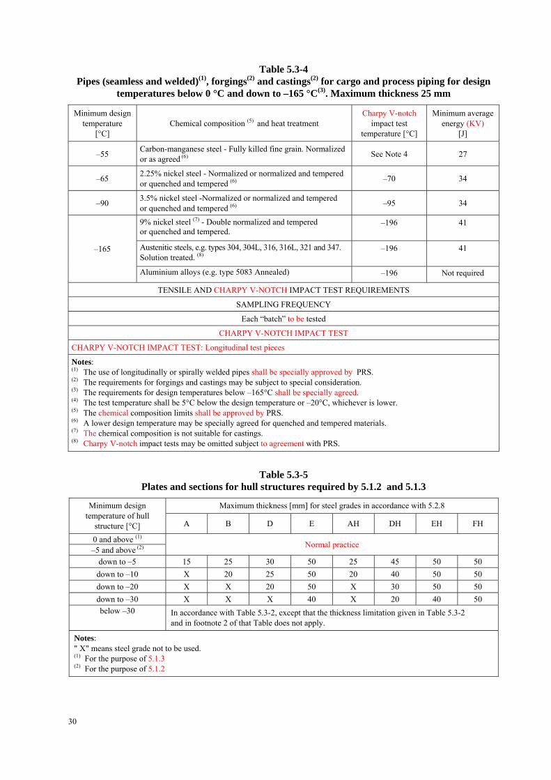
Table 5.3-4 Pipes (seamless and welded)(1), forgings(2) and castings(2) for cargo and process piping for design
temperatures below 0 °C and down to –165 °C(3). Maximum thickness 25 mm
Minimum design temperature
[°C] Chemical composition (5) and heat treatment
Charpy V-notch impact test
temperature [°C]
Minimum average energy (KV)
[J]
–55 Carbon-manganese steel - Fully killed fine grain. Normalized or as agreed (6)
See Note 4 27
–65 2.25% nickel steel - Normalized or normalized and tempered or quenched and tempered (6)
–70 34
–90 3.5% nickel steel -Normalized or normalized and tempered or quenched and tempered (6)
–95 34
9% nickel steel (7) - Double normalized and tempered or quenched and tempered.
–196 41
Austenitic steels, e.g. types 304, 304L, 316, 316L, 321 and 347. Solution treated. (8)
–196
41 –165
Aluminium alloys (e.g. type 5083 Annealed) –196 Not required
TENSILE AND CHARPY V-NOTCH IMPACT TEST REQUIREMENTS
SAMPLING FREQUENCY
Each “batch” to be tested
CHARPY V-NOTCH IMPACT TEST
CHARPY V-NOTCH IMPACT TEST: Longitudinal test pieces
Notes: (1) The use of longitudinally or spirally welded pipes shall be specially approved by PRS. (2) The requirements for forgings and castings may be subject to special consideration. (3) The requirements for design temperatures below –165°C shall be specially agreed. (4) The test temperature shall be 5°C below the design temperature or –20°C, whichever is lower. (5) The chemical composition limits shall be approved by PRS. (6) A lower design temperature may be specially agreed for quenched and tempered materials. (7) The chemical composition is not suitable for castings. (8) Charpy V-notch impact tests may be omitted subject to agreement with PRS.
Table 5.3-5 Plates and sections for hull structures required by 5.1.2 and 5.1.3
Maximum thickness [mm] for steel grades in accordance with 5.2.8 Minimum design temperature of hull
structure [°C] A B D E AH DH EH FH
0 and above (1) –5 and above (2)
Normal practice
down to –5 15 25 30 50 25 45 50 50
down to –10 X 20 25 50 20 40 50 50
down to –20 X X 20 50 X 30 50 50
down to –30 X X X 40 X 20 40 50
below –30 In accordance with Table 5.3-2, except that the thickness limitation given in Table 5.3-2 and in footnote 2 of that Table does not apply.
Notes: " X" means steel grade not to be used. (1) For the purpose of 5.1.3 (2) For the purpose of 5.1.2
30

Table 5.3-6 Minimum material grades for membrane type liquefied gas carries with length exceeding 150 m*
Structural member category Material grade
Longitudinal plating of strength deck where contributing to the longitudinal strength Grade B/AH within 0,4L amidships
Trunk deck plating Class II within 0,4L amidships Continuous longitudinal plating of strength members above the strength deck
– Inner deck plating – Longitudinal strength member plating between
the trunk deck and inner deck
Grade B/AH within 0,4L amidships
* Table 5.3-6 is applicable to membrane type liquefied gas carriers with deck arrangements as shown in Fig.5.3. It may also apply to similar ship types with a “double deck” arrangement above the strength deck.
Fig. 5.3. Typical deck arrangement for membrane type Liquefied Natural Gas Carriers
5.3.2 Materials with alternative chemical composition or mechanical properties may be accepted by special agreement with PRS.
5.3.3 Where post-weld heat treatment is specified or required, the properties of the base materials shall be determined in the heat treated condition in accordance with the applicable table and the weld properties shall be determined in the heat treated condition in accordance with sub-chapter 5.4. In cases where a post-weld heat treatment is applied, the test requirements may be modified at the discretion of PRS.
5.3.4 Where reference is made to hull structural steels, the requirements of PRS Rules, Part IX – Materials and Welding for appropriate grades apply.
5.4 Welding and Non-destructive Testing
5.4.1 General
This sub-chapter shall apply to primary and secondary barriers only, including the inner hull where this forms the secondary barrier. The requirements listed herein are those generally employed for carbon, carbon-manganese, nickel alloy and austenic steels, aluminium alloy and may form the basis for acceptance testing of other material. At the discretion of PRS, Charpy V-notch impact testing of austenic steels and aluminium alloy weldments may be omitted and other tests may be specially required for any material.
5.4.2 Welding Consumables
Welding consumables intended for welding of cargo tanks shall be approved by PRS.
31

Deposited weld metal tests and butt weld tests shall be required for all welding consumables, unless specially agreed otherwise. The results obtained from tensile and Charpy V-notch impact tests shall be approved by PRS. The chemical composition of the deposited weld metal shall be reported for information and approval.
5.4.3 Welding Procedure Tests for Cargo Tanks And Process Pressure Vessels
(a) Number and orientation of test assemblies Welding procedure tests for cargo tanks and process pressure vessels are required for all butt weld. The test assemblies shall be representative of the following:
(i) each base material,
(ii) each type of consumable and welding process,
(iii) each welding position.
For butt welds in plates, the test assemblies shall be so prepared that the rolling direction is parallel to the direction of welding. The range of thickness qualified by each welding procedure test shall be approved by PRS. Radiographic or ultrasonic testing may be performed at the option of the fabricator or PRS.
(b) Required tests
The following welding procedure tests for cargo tanks and process pressure vessels shall be carried out in accordance with PRS Rules Part IX – Materials and Welding, with the specimens made from each test assembly:
(i) Cross-weld tensile tests
(ii) Longitudinal all-weld tensile testing, where required by PRS.
(iii) Transverse bend tests which may be face, root or side bends at the discretion of PRS. However, longitudinal bend tests may be required in lieu of transverse bend tests in cases where the base material and weld metal have different strength levels.
(iv) One set of three Charpy V-notch impact test specimens generally at each of the following indications (see Fig. 5.2.2.3): (1) centre line of the welds (2) fusion line (F.L.) (3) 1 mm from the F.L. (4) 3 mm from the F.L. (5) 5 mm from the F.L.
(v) Macrosection, microsection and hardness survey may also be required at the discretion of PRS.
5.4.4 Test Requirements
(a) Tensile tests Generally, tensile strength shall not be less than the specified minimum tensile strength for the appropriate parent materials. It may also be accepted subject to agreement with PRS that the transverse weld tensile strength is not to be less than the specified minimum tensile strength for the weld metal, where the weld metal has the tensile strength lower than that of the parent metal. In every case, the position of fracture shall be reported for information.
(b) Bend tests No fracture is acceptable after 180° bend over a former diameter of 4t where t is the thickness of the test pieces.
(c) Charpy V-notch impact tests Charpy V-notch impact test shall be conducted at the temperature prescribed for the base material being joined. The results of weld metal Charpy V-notch impact tests, minimum average energy (KV), shall be not less than 27 J. The weld metal requirements for subsize specimens and single energy values shall be in accordance with 5.2.3. The results of fusion line and heat affected zone Charpy V-notch impact tests, shall show a minimum average energy (KV), are to be generally in accordance with the transverse or longitudinal requirements of the base material, whichever is applicable and for
32

subsize specimens, the minimum average energy (KV), are to be generally in accordance with 5.2.3. If the material thickness does not permit machining either full size or standard subsize specimens, the testing procedure and acceptance standards shall be approved by PRS.
5.4.5 Fillet welding procedure tests
Fillet welding procedure tests shall be in accordance with the PRS Rules. In such cases, welding consumables shall be selected which exhibit satisfactory Charpy V-notch impact properties.
5.4.6 Welding procedure tests for secondary barriers
Welding procedure tests for secondary barriers shall be in accordance with the PRS Rules.
5.4.7 Welding Procedure Tests for Piping
Welding procedure tests for piping are required and are to be similar to those detailed for cargo tanks provided in 5.4.3. Unless specially agreed otherwise, the test requirements are to be in accordance with 5.4.4.
5.4.8 Production Weld Tests
For all cargo tanks and process pressure vessels, except for integral and membrane tanks, production tests shall generally be performed for approximately each 50 m of butt weld joints and shall be representative of each welding position. For secondary barriers, the same type production tests as required for primary tanks shall be performed, except that the number of tests may be reduced subject to the agreement with PRS. Tests, other than those specified, may be required for cargo tanks or secondary barriers at the discretion of PRS. Test requirements shall be in accordance with 5.4.4.
The quality assurance/quality control programme shall ensure the continued conformity of the production welds as defined in the material manufacturer’s quality manual.
(a) Type A and type B independent tanks and semi-membrane tanks The production tests for type A and type B independent tanks and semi-membrane tanks shall include the following tests: Bend tests and, where required for procedure tests, one set of three Charpy V-notch impact tests shall be made for each 50 m of weld. The Charpy V-notch impact tests shall be made with specimens having the notch alternately located in the centre of the weld and in the heat affected zone (most critical location based on procedure qualification results). For austenitic steels, all notches shall be in the centre of the weld.
(b) Type C independent tanks and process pressure vessels In addition to the tests listed in (a), for type C independent tanks and process pressure vessels, transverse weld tensile tests are also required.
(c) Integral and membrane tanks The test requirements for integral and membrane tanks are the same as the applicable test requirements listed in 5.4.3.
5.4.9 Non-destructive Testing
All test procedures and acceptance standards shall be in accordance with PRS, unless the designer specifies a higher standard in order to meet design assumptions.
Radiographic testing shall be used, in principle, to detect internal defects. However, an approved ultrasonic test procedure in lieu of radiographic testing may be conducted, but, in addition, supplementary radiographic testing at selected locations shall be carried out to verify the results. Radiographic and ultrasonic testing records shall be retained. The quality assurance/quality control programme shall ensure the continued conformity of the non-destructive testing of welds, as defined in the material manufacturer's quality manual.
33
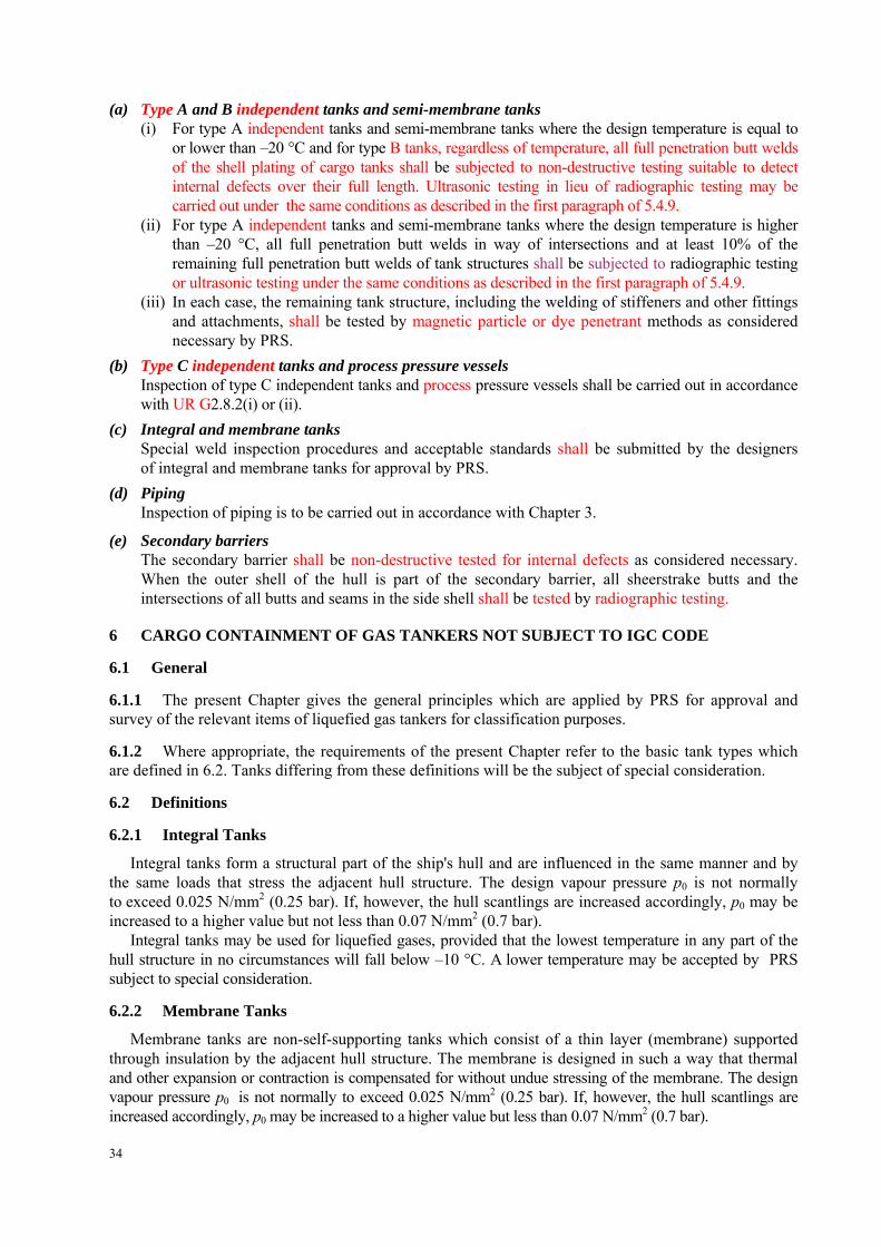
(a) Type A and B independent tanks and semi-membrane tanks (i) For type A independent tanks and semi-membrane tanks where the design temperature is equal to
or lower than –20 °C and for type B tanks, regardless of temperature, all full penetration butt welds of the shell plating of cargo tanks shall be subjected to non-destructive testing suitable to detect internal defects over their full length. Ultrasonic testing in lieu of radiographic testing may be carried out under the same conditions as described in the first paragraph of 5.4.9.
(ii) For type A independent tanks and semi-membrane tanks where the design temperature is higher than –20 °C, all full penetration butt welds in way of intersections and at least 10% of the remaining full penetration butt welds of tank structures shall be subjected to radiographic testing or ultrasonic testing under the same conditions as described in the first paragraph of 5.4.9.
(iii) In each case, the remaining tank structure, including the welding of stiffeners and other fittings and attachments, shall be tested by magnetic particle or dye penetrant methods as considered necessary by PRS.
(b) Type C independent tanks and process pressure vessels Inspection of type C independent tanks and process pressure vessels shall be carried out in accordance with UR G2.8.2(i) or (ii).
(c) Integral and membrane tanks Special weld inspection procedures and acceptable standards shall be submitted by the designers of integral and membrane tanks for approval by PRS.
(d) Piping Inspection of piping is to be carried out in accordance with Chapter 3.
(e) Secondary barriers The secondary barrier shall be non-destructive tested for internal defects as considered necessary. When the outer shell of the hull is part of the secondary barrier, all sheerstrake butts and the intersections of all butts and seams in the side shell shall be tested by radiographic testing.
6 CARGO CONTAINMENT OF GAS TANKERS NOT SUBJECT TO IGC CODE
6.1 General
6.1.1 The present Chapter gives the general principles which are applied by PRS for approval and survey of the relevant items of liquefied gas tankers for classification purposes.
6.1.2 Where appropriate, the requirements of the present Chapter refer to the basic tank types which are defined in 6.2. Tanks differing from these definitions will be the subject of special consideration.
6.2 Definitions
6.2.1 Integral Tanks
Integral tanks form a structural part of the ship's hull and are influenced in the same manner and by the same loads that stress the adjacent hull structure. The design vapour pressure p0 is not normally to exceed 0.025 N/mm2 (0.25 bar). If, however, the hull scantlings are increased accordingly, p0 may be increased to a higher value but not less than 0.07 N/mm2 (0.7 bar).
Integral tanks may be used for liquefied gases, provided that the lowest temperature in any part of the hull structure in no circumstances will fall below –10 °C. A lower temperature may be accepted by PRS subject to special consideration.
6.2.2 Membrane Tanks
Membrane tanks are non-self-supporting tanks which consist of a thin layer (membrane) supported through insulation by the adjacent hull structure. The membrane is designed in such a way that thermal and other expansion or contraction is compensated for without undue stressing of the membrane. The design vapour pressure p0 is not normally to exceed 0.025 N/mm2 (0.25 bar). If, however, the hull scantlings are increased accordingly, p0 may be increased to a higher value but less than 0.07 N/mm2 (0.7 bar).
34

The definition of membrane tanks does not exclude designs such as those in which non-metallic membranes are used or in which membranes are included or incorporated in insulation. Such designs, however, require special consideration by PRS.
6.2.3 Semi-membrane Tanks
Semi-membrane tanks are non-self-supporting tanks in the loaded condition and consist of a layer, parts of which are supported through insulation by the adjacent hull structure, whereas the rounded parts of this layer connecting the above – mentioned supported parts are designed also to accommodate the thermal and other expansion or contraction. The design vapour pressure p0 is not normally to exceed 0.025 N/mm2 (0.25 bar). If, however, the hull scantlings are increased accordingly, p0 may be increased to a higher value but less than 0.07 N/mm2 (0.7 bar).
6.2.4 Independent Tanks
Independent tanks are self-supporting; they do not form part of the ship hull and are not essential to the hull strength. Three categories of independent tanks are considered: (i) Type A independent tanks which are designed primarily using Classification Society classical
structural analysis procedures. Where such tanks are primarily constructed of plane surfaces (gravity tanks), the design vapour pressure p0 is to be less than 0.07 N/mm2 (0.7 bar).
(ii) Type B independent tanks which are designed using model tests, refined analytical tools and analysis methods to determine stress levels, fatigue life and crack propagation characteristics. Where such tanks are primarily constructed of plane surfaces (gravity tanks), the design vapour pressure p0 is to be less than 0.07 N/mm2 (0.7 bar).
(iii) Type C independent tanks (also referred to as pressure tanks) are tanks meeting pressure vessel criteria and having a design vapour pressure p0 not less than:
2/300 1.02.0 Ap [N/mm2]
2/300 2 ACp [bar]
where:
2
0185.0
A
mA
m – design primary membrane stress [N/mm2]; A – allowable dynamic membrane stress (double amplitude at probability level Q = 10-8), – 55 N/mm2 for ferritic-perlitic, martensitic and austenitic steels, – 25 N/mm2 for aluminium alloy (5083-0);
(for other materials, the value of A will be determined in agreement with PRS); C – characteristic tank dimension to be taken as the greatest of h: 0.75b or 0.45l;
h – height of tank (dimension in ship’s vertical direction) [m]; b – width of tank (dimension in ship’s transverse direction) [m]; l – length of tank (dimension in ship’s longitudinal direction) [m];
0 – relative density of cargo (0 = 1 for fresh water) at the design temperature. However, PRS may allocate a tank complying with the above criterion to type A or type B,
dependent on the configuration of the tank and the arrangement of its supports and attachments.
6.2.5 Design Vapour Pressure
The design vapour pressure p0 is the maximum gauge pressure at the top of the tank which has been used in the design of the tank. (i) For cargo tanks where there is no temperature control and where the pressure of the cargo is only
dictated by the ambient temperature, p0 is not to be less than the vapour pressure of the cargo at a temperature of 45 °C. However, lesser values of this temperature may be accepted by PRS for ships operating in restricted areas or on voyages of restricted duration and account may be taken in such cases of a possible insulation of the tanks. On the other hand, higher values of this temperature may be required for ships permanently operating in areas of high ambient temperature.
35

(ii) In all cases, including (i), p0 is not to be less than the maximum allowable relief valve setting (MARVS).
(iii) Subject to special consideration and to the limitations given in 6.2.1 to 6.2.4 for the various tank types, a vapour pressure higher than p0 may be accepted in harbour conditions where dynamic loads are reduced.
6.2.6 Design Temperature
The design temperature for selection of materials is the minimum temperature at which cargo may be loaded and/or transported in the cargo tanks.
Provisions to the satisfaction of PRS are to be made so that the tank or cargo temperature cannot be lowered below the design temperature.
6.3 Design Loads
6.3.1 General
(a) Tanks, together with their supports and other fixtures are to be designed taking into account proper combinations of the following loads: – internal pressure, – external pressure, – dynamic loads due to the motions of the ship, – thermal loads, – sloshing loads, – loads corresponding to ship deflection, – tank and cargo weight with the corresponding reactions in way of supports, – insulation weight, – loads in way of towers and other attachments.
The extent to which these loads are to be considered depends on the type of tank.
(b) Account is also to be taken of the loads corresponding to the pressure test referred to in 6.10.
(c) Account is also to be taken of an increase of vapour pressure in harbour conditions (see 6.2.5 (iii)).
(d) The tanks are to be designed for the most unfavourable static heel angle within the range of 0° to 30° without exceeding allowable stresses given in 6.5.
6.3.2 Internal Pressure
(a) The following formula gives the value of internal pressure head egh , in N/mm2 or bar, resulting from
the design vapour pressure p0 and the liquid pressure defined in 6.3.2 (b), but not including effects of liquid sloshing:
max0 gdeq hph
Equivalent procedures may be applied.
(b) The internal liquid pressures are those created by the resulting acceleration of the centre of gravity of the cargo due to the motions of the ship (see 6.3.4). The following formula gives the value of internal pressure head hgd, in N/mm2 or bar, resulting from combined effects of gravity and dynamical acceleration:
51002.1
Zahgd [N/mm2]
41002.1
Zahgd [bar]
where a – dimensionless acceleration (i.e. relative to the acceleration of gravity), resulting from
gravitational and dynamic loads, in an arbitrary direction (see Fig. 6.3.7-1);
36

Z – largest liquid height [m] above the point where the pressure is to be determined, measured from the tank shell in the direction (see Fig. 6.3.7-2). Small tank domes not considered to be part of the accepted total volume of the cargo tank need not be considered when determining Z.
= the maximum density of the cargo [kg/m3] at the design temperature.
The direction which gives the maximum value (hgd)max of hgd is to be considered. Where acceleration components in three directions need to be considered, an ellipsoid is to be
used instead of the ellipse in Fig. 6.3.7-1. The above formula applies to full tanks.
6.3.3 External Pressure
External design pressure loads are to be based on the difference between the minimum internal pressure (maximum vacuum) and the maximum external pressure to which any portion of the tank may be subjected simultaneously.
6.3.4 Dynamic Loads Due to Ship Motions
(a) The determination of dynamic loads is to take account of the long-term distribution of ship motions, including the effects of surge, sway, heave, roll, pitch and yaw on irregular seas which the ship will experience during its operating life (normally taken to correspond to 108 wave encounters). Account may be taken of reduction in dynamic loads due to necessary speed reduction and variation of heading when this consideration has also formed part of the hull strength assessment.
(b) For design against plastic deformation and buckling the dynamic loads are to be taken as the most probable largest loads the ship will encounter during its operating life (normally taken to correspond to a probability level of 10-8). See Appendix 1 for guidance.
(c) When design against fatigue is to be considered, the dynamic spectrum is to be determined by the long-term distribution calculation based on the operating life of the ship (normally taken to correspond to 108 wave encounters). If simplified dynamic loading spectra are used for the estimation of the fatigue life, these are to be specially considered by PRS.
(d) In order to practically apply crack propagation estimates, simplified load distribution over a period of 15 days may be used. Such distributions may be obtained as indicated in Fig. 6.3.7-3.
(e) Ships for restricted service will be given special consideration. (f) The accelerations acting on tanks are estimated at their centre of gravity and include the following
components: vertical acceleration: motion acceleration of heave, pitch and possibly, roll (normal to the ship base); transverse acceleration: motion acceleration of sway, yaw and roll, gravity component of roll; longitudinal acceleration: motion acceleration of surge and pitch, gravity component of pitch.
Procedures for the periodic checking of the secondary barrier during the life of the ship are to be submitted to PRS as a condition of the approval of the cargo containment system.
6.3.5 Sloshing Loads
(a) When partial filling is contemplated, the risk of significant loads due to sloshing induced by any of the ship motions referred to in 6.3.4 (f) is to be considered.
(b) When risk of significant sloshing induced loads is found to be present, special tests and calculations will be required.
6.3.6 Thermal Loads
(a) Transient thermal loads during cooling down periods are to be considered for tanks intended for cargoes with a boiling point below –55 °C.
(b) Stationary thermal loads are to be considered for tanks where design, supporting arrangement and operating temperature may give rise to significant thermal stress.
37

6.3.7 Loads on Supports
See 6.6.
a = resulting acceleration (static and dynamic) in arbitrary direction ; ay = transverse component of acceleration; az = vertical component of acceleration.
Fig. 6.3.7-1 Acceleration ellipse
Fig. 6.3.7-2 Determination of internal pressure heads
38

Response cycles
o = most probable maximum stress over the life of the ship Response cycle scale is logarithmic; the value of 2x10⁵ is given as an example of estimate.
Fig. 6.3.7-3 Simplified load distribution
6.4 Structural Analysis
6.4.1 Integral Tanks
The structural analysis of integral tanks is to be performed in accordance with the Rules, Part II – Hull regarding hull structure.
6.4.2 Membrane Tanks
(a) For membrane tanks, the effects of all static and dynamic loads are to be considered to determine the suitability of the membrane and of the associated insulation with respect to plastic deformation and fatigue.
(b) Before approval is granted, a model of both the primary and secondary barrier, including corners and joints, is normally to be tested to verify that it will withstand the expected combined strains due to static, dynamic and thermal loads. Test conditions are to represent the most extreme service conditions that tank will see in its life. Material tests are to ensure that ageing is not liable to prevent the materials from carrying out their intended function.
(c) For the purpose of the test referred to in 6.4.2 (b), a complete analysis of the particular motions, accelerations and response of ships and tanks is to be performed, unless these data are available from similar ships.
(d) Special attention is to be paid to the possible collapsing of the membrane due to an overpressure in the interbarrier space, to a possible vacuum in the tanks, to the sloshing effects and to hull vibration effects.
(e) The structural analysis of the hull is to be performed in accordance with the Rules, Part II – Hull, taking into account the internal pressure as indicated in 6.3.2. Special attention is, however, to be paid to deformations of the hull and their compatibility with the membrane and the associated insulation. Inner hull plating thickness is to meet at least the requirements of the Rules, Part II – Hull for deep tanks, taking into account the internal pressure as indicated in 6.3.2. The allowable stress for the membrane, membrane – supporting material and insulation will be determined by PRS in each particular case.
6.4.3 Semi-membrane Tanks
Structural analysis is to be performed in accordance with the requirements for membrane tanks or independent tanks as appropriate, taking into account the internal pressure as indicated in 6.3.2.
39

6.4.4 Type A Independent Tanks
(a) The structural analysis is normally performed in accordance with the Rules, Part II – Hull for hull structure taking into account the internal pressure as indicated in 6.3.2. The cargo tank plating thickness is to meet at least the requirements of the Rules, Part II – Hull for deep tanks, taking into account the internal pressure as indicated in 6.3.2 and any corrosion allowance required by 6.5.2.
(b) For parts such as structure in way of supports stresses are to be determined by direct calculations, taking into account the loads, referred to in 6.3, as far as applicable and the ship deflection in way of supports.
6.4.5 Type B Independent Tanks
(a) The effects of all dynamic and static loads are to be used to determine the suitability of the structure with respect to: – plastic deformation, – buckling, – fatigue failure, – crack propagation.
Statistical wave load analysis in accordance with 6.3.4, finite element analysis or similar methods and fracture mechanics analyses or equivalent approach, are to be carried out.
(b) A three – dimensional analysis is to be carried out to evaluate the stress levels contributed by the ship’s hull. The model for this analysis is to include the cargo tank with its supporting and keying system, as well as a reasonable part of the hull.
(c) A complete analysis of the particular ship accelerations and motions in irregular waves and of the response of ships and tanks to these forces and motions is to be performed unless these data are available from similar ships.
(d) Buckling analysis is to consider the maximum construction tolerances.
(e) Where deemed necessary by PRS , model tests may be required to determine stress concentration factors and fatigue life of structural elements.
(f) The cumulative effect of the fatigue load is to comply with the following formula:
wji
i CNN
n
310
where: ni = number of stress cycles at each stress level during the life of the ship; Ni = number of cycles to fracture for the respective stress level according to the Wöhler (S – N)
curve; Nj = number of cycles to fracture for the fatigue loads due to loading and unloading.
Cw 0.5, except that PRS may give special consideration to the use of a value greater than 0.5 but not greater than 1.0, dependent on the test procedure and data used to establish the Wöhler curve (S - N) curve.
6.4.6 Type C Independent Tanks
Structural analysis is to be performed in accordance with Chapter 2.
6.5 Allowable Stresses – Corrosion Allowances
6.5.1 Allowable Stresses
(a) For integral tanks, allowable stresses are normally those given for hull structure by the Rules, Part II – Hull.
(b) For membrane tanks, see 6.4.2 (e).
40

(c) For independent tanks type A primarily constructed of plane surfaces, the bending stresses for primary and secondary members (stiffeners, web frames, stringers, girders) when calculated by classical analysis procedures are not to exceed the lower of 0.75F or 0.38B for carbon-manganese steels and aluminium alloys. However, if detailed calculations are carried out for the primary members, the equivalent stresses c, as defined in 6.5.1 (g) may be increased over that indicated above to a value acceptable to PRS ; calculations have to take into account the effects of bending, shear, axial and torsional deformations, as well as the hull/cargo tank interaction forces due to the deflection of the double and cargo tank bottoms. For F and B, see 6.5.1 (h).
(d) For independent tanks type B primarily constructed of bodies of revolution, the allowable stresses are not to exceed the following:
m f L 1.5f b 1.5F L + b 1.5F m + b 1.5F
where: m = equivalent primary general membrane stress; L = equivalent primary local membrane stress; b = equivalent primary bending stress; f = the lesser of B/A or F /B; F = the lesser of B/C or F /D.
A, B, C and D have the following values:
Material A B C D
C-Mn steels and Ni steels Austenitic steels Aluminium alloys
3 3.5 4
2 1.6 1.5
3 3 3
1.5 1.5 1.5
For B and F, see 1.5.1 (h).
(e) For independent tanks type B, primarily constructed of plane surfaces, PRS may require compliance with additional or other stress criteria.
(f) For independent tanks type C, see Chapter 2.
(g) For the purpose of para. 6.5.1 (a)-(f), equivalent stresses c (von Mises, Huber) are determined as follows:
222 3 yxyxyxc
where: x = total normal stress in x direction; xy = total shear stress in y-x plane; y = total normal stress in y direction.
Unless other methods of calculation are justified, the total stresses are calculated according to the following formulae for independent tanks type B:
2.. )( dynxstxx
2.. )( dynystyy
2. )( dynxyxyxy
where: x.st, xy.st and xy.st are static stresses, x.dyn, xy.dyn and xy.dyn are dynamic stresses, determined separately from acceleration components and hull strain components due to deflection and torsion.
41

(h) For the purpose of para. 6.5.1 (a) – (g): F – specified minimum upper yield stress at room temperature. If the stress-strain curve does not
show a defined yield stress, the 0.2 % proof stress applies. For welded connections in aluminium alloys, the proof stress in annealed conditions is to be used.
B – specified minimum tensile strength at room temperature. For welded connections in aluminium alloys, the tensile strength in annealed conditions is to be used.
The above properties are to correspond to the minimum specified mechanical properties of the material, including the weld metal in the as – fabricated condition. Subject to special consideration by PRS, advantage may be taken of enhanced yield stress and tensile strength at low temperature.
(i) Allowable stresses for materials other than those covered by Chapter 5 will be subject to special approval by PRS in each separate case. Stresses may be further limited by fatigue analysis, crack propagation analysis and buckling criteria.
6.5.2 Corrosion Allowances
(a) No corrosion allowance is generally required in addition to the thickness resulting from the structural analysis. However, where there is no environmental control around the tank (inerting, etc.) or where the cargo is of a corrosive nature, PRS may require a suitable corrosion allowance.
(b) For pressure tanks, corrosion allowance is given in Chapter 2.
6.6 Supports
6.6.1 Cargo tanks are to be supported by the hull in a manner which will prevent bodily movement of the tank under static and dynamic loads while allowing contraction and expansion of the tank under temperature variations and hull deflections without undue stressing of the tank and of the hull.
6.6.2 The tanks with supports are also to be designed for a static inclination of 30° without exceeding allowable stresses given in 6.5.
6.6.3 The supports are to be calculated for the most probable largest severe resulting acceleration, taking into account rotational as well as translational effects. This acceleration in a given direction may be determined as shown in Fig. 6.3.7-1. The half axes of the 'acceleration ellipse' are determined according to 6.3.4 (b).
6.6.4 Suitable supports are to be provided to withstand a collision force acting on the tank corresponding to one-half the weight of the tank and cargo in the forward direction and one-quarter the weight of the tank and cargo in the aft direction without deformation likely to endanger the tank structure.
6.6.5 The loads, mentioned in 6.6.2 and 6.6.4, need not be combined with each other or with wave induced loads.
6.6.6 For independent tanks and, where appropriate, for membrane and semi-membrane tanks, provisions are to be made to key the tanks against rotational effects referred to in 6.6.3.
6.6.7 Antiflotation chocks are to be provided for independent tanks. The antiflotation chocks are to be suitable to withstand an upward force caused by an empty tank in a hold space flooded to the summer load draught of the ship, without plastic deformation likely to endanger the hull structure.
6.7 Secondary Barrier
6.7.1 When the cargo temperature at atmospheric pressure is below –10 °C, a secondary barrier is to be provided, if required by 6.7.3, to act as a temporary containment for any envisaged leakage of liquid cargo through the primary barrier.
6.7.2 When the cargo temperature at atmospheric pressure is not below –55 °C, the hull structure may act as a secondary barrier. In such a case:
(i) the hull material is to be suitable for the boiling point at atmospheric pressure (see Chapter 5);
(ii) the design is to be such that this temperature will not result in unacceptable hull stresses.
42

6.7.3 The requirements for a secondary barrier in relation to tank type are as given in Table 6.7.3. Table 6.7.3 indicates the basic requirements with respect to secondary barrier. For tanks which differ
from the basic tank types as defined in 6.2, the secondary barrier requirements will be decided by PRS in each separate case.
Table 6.7.3
Cargo temperature tb at atmospheric pressure
tb –55 °C –55 °C tb –10 °C tb –10 °C
Basic tank type Separate secondary barrier where required Hull may act as secondary barrier
Integral Tank type not normally allowed 1
Membrane Complete secondary barrier No secondary
barrier required
Semi-membrane Complete secondary barrier 2
Independent type A Complete secondary barrier
Independent type B Partial secondary barrier
Independent type C No secondary barrier required
Notes: 1 A complete secondary barrier will be normally required if cargoes with a value of tb below –10 °C are permitted in accordance
with 6.2.1. 2 In the case of semi-membrane tanks which comply in all respects with the provisions applicable to independent tanks type
B, except for the manner of support, PRS may consider the possibility of accepting a partial secondary barrier.
6.7.4 The secondary barrier is to be designed so that:
(i) it is capable of containment of any envisaged leakage of liquid cargo for a period of at least 15 days, unless different requirements apply for particular voyages. This condition is to be fulfilled taking into account the load spectrum defined in 6.3.4 (d);
(ii) it will prevent lowering of the temperature of the ship structure to an unsafe level in the case of leakage of the primary barrier (see 6.8.2);
(iii) the mechanism of failure for the primary barrier does not also cause the failure of the secondary barrier and vice-versa.
6.7.5 The functions of the secondary barrier are to be ensured assuming a static angle of heel equal to 30°.
6.7.6 Where a partial secondary barrier is required, its extent is to be determined on the basis of cargo leakage corresponding to the extent of failure resulting from the load spectrum defined in 6.3.4 (d) after the initial detection of a primary barrier leak. Due account may be taken of liquid evaporation, rate of leakage, reliable pumping capacity and other relevant factors. In all cases, however, the inner bottom in way of cargo tanks is to be protected against liquid cargo. Clear of the partial secondary barrier, provisions are to be made to deflect any liquid cargo down into the space between the primary and secondary barriers and to keep the temperature of the hull structure to a safe level (spray-shield).
6.7.7 The secondary barrier is to be capable of being periodically checked for its effectiveness.
6.8 Insulation
6.8.1 When liquefied gas is carried at a temperature below –10 °C, suitable insulation is to be provided to ensure that the minimum temperature of the hull structure does not fall below the minimum allowable service temperature given for the concerned grade of steel in Chapter 5 when the cargo tanks are at their design temperature and the ambient temperatures are 5°C for air and 0 °C for sea water. The above conditions may generally be used for world wide service. However, higher values of the ambient temperatures may be accepted by PRS for ships operated in restricted areas. On the other hand, attention is drawn to the fact that lesser values of the ambient temperatures may be fixed by National Authorities.
43
6.8.2 Where a complete or partial secondary barrier is required, calculations are to be made with the same assumptions as in 6.8.1 to check that the minimum temperature of the hull structure does not fall below the minimum allowable service temperature given for the concerned grade of steel in Chapter 5. The complete or partial secondary barrier is then to be assumed to be at the cargo temperature at atmospheric pressure.
6.8.3 Calculations required by 6.8.1 and 6.8.2 are to be made assuming still air and still water. In the case, referred to in 6.8.2, the cooling effect of the rising boil-off vapour from the leaked cargo is to be considered in the heat transmission studies. For members connecting inner and outer hulls, the mean temperature may be considered for determining the steel grades.
6.8.4 In all cases, referred to in 6.8.1 and 6.8.2 and for the ambient temperature conditions of 5 °C for air and 0 °C for sea water, approved means of heating transverse hull structural material may be used to ensure that the temperature of this material does fall below the minimum allowable values. If lower ambient temperatures are specified, approved means of heating may also be used for longitudinal hull structural material, provided this material remains suitable for the temperature conditions of 5 °C for air and 0 °C for sea water without heating. Such means of heating is to comply with the following requirements: (i) sufficient heat is to be available to maintain the hull structure above the minimum allowable
temperature in the conditions referred to in 6.8.1 and 6.8.2; (ii) the heating systems are to be arranged so that, in the event of a failure in any part of the system,
standby heating can be maintained equal to not less than 100% of the theoretical heat load; (iii) the heating systems are to be considered as essential auxiliaries; (iv) the engineering of the heating systems is to be in accordance with the requirements of PRS.
6.8.5 In determining the insulation thickness, due regard is to be paid to the amount of acceptable boil-off in association with the reliquefaction plant on board, main propulsion machinery or other temperature control system.
6.9 Materials
6.9.1 The shell and deck plating of the ship and all stiffeners attached thereto, are to be in accordance with the Rules, Part II – Hull, unless the calculated temperature of the material in the design condition is below –5 °C due to the effect of the low temperature cargo, in which case the material is to be in accordance with Table 5.3-5, assuming ambient sea and air temperatures of 0 °C and 5 °C, respectively. In the design condition, the complete or partial secondary barrier is to be assumed to be at the cargo temperature at atmospheric pressure and for tanks without secondary barriers, the primary barrier is to be assumed to be at the cargo temperature.
6.9.2 Hull material forming the secondary barrier is to be in accordance with Table 5.3-2.
6.9.3 Materials used in the construction of cargo tanks are to be in accordance with Tables 5.3-1, 5.3-2 or 5.3-3.
6.9.4 All other materials used in the construction of the ship which are subject to reduced temperature due to the cargo and which do not form part of the secondary barrier are to be in accordance with Table 5.3-5 for temperature determined by 6.8. This includes inner bottom plating, longitudinal bulkhead plating, transverse bulkhead plating, floors, webs, stringers and all attached stiffening members.
6.9.5 The insulation materials are to be suitable for loads which may be imposed on them by the adjacent structure.
6.9.6 Where applicable, insulation materials are to have suitable properties of fire resistance and are to be adequately protected against penetration of water vapour and mechanical damage.
6.9.7 Insulation materials are to be tested and found acceptable with regard to the following properties as applicable: – compatibility with the cargo,
44

– solubility in the cargo, – absorption of the cargo, – shrinkage, – ageing, – closed cell content, – density, – mechanical properties, – thermal expansion, – abrasion, – cohesion, – thermal conductivity, – resistance to vibrations, – resistance to fire and flame spread.
6.9.8 The procedures for quality control of insulation materials during fabrication and/or in situ erection are to be to the satisfaction of PRS.
6.9.9 Where powder or granulated insulation is used, the arrangements are to be such as to prevent compacting of the material due to vibrations.
The design is to incorporate means to ensure that the material remains sufficiently buoyant to maintain the required thermal conductibility and also prevent any undue increase of pressure on the cargo containment system.
6.10 Construction and Testing
6.10.1 All welded joints of the shell of independent tanks are to be of the butt-weld full penetration type. For dome- to -shell connections, PRS may approve fillet welds of the full penetration type. Except for small penetrations on domes, nozzle welds are also generally to be designed with full penetration. For tank type C, see Chapter 2.
6.10.2 Workmanship is to be to the satisfaction of PRS. Inspection of welds including non-destructive testing is to be in accordance with Chapter 5.
6.10.3 For membrane tanks, quality assurance measures, weld procedure qualification, design details, materials, construction, inspection and production testing of components are to be to standards developed during the prototype testing programme.
6.10.4 For semi-membrane tanks, the relevant requirements for independent tanks or for membrane tanks are to be applied as appropriate.
6.10.5 Integral tanks are to be hydrostatically or hydropneumatically tested in accordance with Publication No 21/P – Testing of the Hull Structures. The test is, in general, to be performed so that the stresses approximate, as far as practicable, to the design stresses and that the pressure at the top of the tank corresponds at least to the MARVS.
6.10.6 For ships fitted with membrane or semi-membrane tanks, cofferdams and all spaces which may normally contain liquid and are adjacent to the hull structure supporting the membrane are to be hydrostatically or hydropneumatically tested in accordance with the requirements of Publication No. 21/P. Pipe tunnels and other compartments which do not normally contain liquid are not required to be hydrostatically tested.
In addition, the ship hold structure supporting the membrane is to be subjected to a tightness testing.
6.10.7 Each independent tank is to be subjected to a hydrostatic or hydropneumatic test. For tanks type A, this test is to be performed so that the stresses approximate, as far as practicable, to the design stresses and that the pressure at the top of the tank corresponds at least to the MARVS. When the hydropneumatic test is performed, the conditions are to simulate, as far as possible, the actual loading of the tank and of its supports. For tanks type B, the test is to be performed as for tanks type A. Moreover, the maximum primary
45

membrane stress or maximum bending stress in a primary membrane under test conditions is not to exceed 90% of the yield strength of the material (as fabricated) at the test temperature.
To ensure that this condition is satisfied, when calculations indicate that this stress exceeds 75% of the yield strength, the prototype test is to be monitored by the use of strain gauges or other suitable equipment. For tanks type C, see Chapter 2.
6.10.8 All tanks are to be subjected to a tightness test which may be performed in combination with the pressure test mentioned above or separately.
6.10.9 The requirements with respect to inspection of the secondary barrier will be decided by PRS in each separate case.
6.10.10 On ships using independent tanks type B, at least one tank and its support is to be instrumented to confirm stress levels unless the design and arrangement for the size of the ship involved are supported by full scale experience. Similar instrumentation may be required by PRS for independent tanks type C, dependent on their configuration and on the arrangement of their supports and attachments.
6.10.11 The ship is to be surveyed during the initial cool-down, loading and discharging of the cargo to verify the overall performance of the cargo containment system for compliance with the design parameters.
Records of the performance of the components and equipment essential to verify the design parameters are to be maintained and these records are to be available to PRS.
6.10.12 Heating arrangements, if fitted in accordance with 6.8.4, are to be tested for compliance with the design requirements.
6.10.13 Inspection of the hull for cold spots is to be performed following the first loaded voyage.
Note:
The requirements specified in paras. 6.10.5 to 6.10.13 are also given in Publication No. 21/P – Testing of the Hull Structures.
46

APPENDIX 1
Guidance formulae for acceleration components
In pursuance of 6.3.4, the following formulae are given as guidance for the components of acceleration due to ship's motions in the case of ships with L > 50 m. These formulae correspond to a probability level of 10-8 in the North Atlantic.
Vertical acceleration
2/322
0
6.005.0
453.51
Bz CL
x
Laa
Transverse acceleration
22
0 6.0105.05.26.0
B
zKK
L
xaa y
Longitudinal acceleration
AAax 25.006.0 2
with
BCL
zLA
6.05
12007.0
where: L – length of ship between perpendiculars, [m]; CB – block coefficient; B – greatest moulded breadth, [m]; x – longitudinal distance, [m], from amidships to the centre of gravity of the tank with contents; x is
positive forward of amidships, negative aft of amidships; z – vertical distance, [m], from the ship's actual waterline to the centre of gravity of the tank with
contents; z is positive above and negative below the waterline.
L
L
L
Va
/600342.00
V = service speed, [knots].
Generally, K = 1.0. For particular loading conditions and hull forms, determination of K according to the formulae below may be necessary:
B
GK M13
0.1K
where GM = metacentric height, [m].
ax, ay and az are the maximum dimensionless (i.e. relative to the acceleration of gravity) accelerations in the respective directions and they are considered as acting separately for calculation purposes;
az does not include the component of the static weight; ay includes the component of the static weight in the transverse direction due to rolling; ax includes the component of the static weight in the longitudinal direction due to pitching.
47

7 MISCELLANEOUS
7.1 Closing Devices for Air Intakes
7.1.1 The closing devices that need not be operable from within the single spaces may be operated from centralized control positions.
7.1.2 Engine room casings, cargo machinery spaces, electric motor rooms and steering gear compartments are generally considered as spaces not covered by paragraph 3.2.6 in IGC Code and therefore the requirement for closing devices need not be applied to these spaces.
7.1.3 The closing devices are to give a reasonable degree of gas tightness. Ordinary steel fire-flaps without gaskets/seals are not to be considered satisfactory.
7.1.4 Regardless of this interpretation, the closing devices are to be operable from outside of the protected space (SOLAS regulation II-2/5.2.1.1).
7.1.5 With regard to openings permitted to be immersed within ranges specified in 2.7.2.1 of IGC Code, ventilators complying with International Convention on Load Lines, regulation 19(4) that for operational reasons have to remain open to supply air to the engine room or emergency generator room (if the same is considered buoyant in the stability calculation or protecting openings leading below) for the effective operation of the ship are not included in “other openings capable of being closed weathertight” category.
7.2 Examination before and after the First Loaded Voyage
7.2.1 Certification
7.2.1.1 The following initial certificates are to be “conditionally” issued at delivery subject to satisfactory completion of the first cargo loading and unloading survey requirements below in the presence of a Surveyor: a) Classification Certificate b) Short Term Certificate of Fitness for the Carriage of Liquefied Gases in Bulk
Note: The conditions may either be stated on the Classification Certificate or issued as a Condition of Class/Outstanding
Recommendation in the vessel’s Record.
7.2.1.2 Survey Requirements
.1 First Loading (considered to be full loading):
a) Priority to be given to latter stages of loading (approximately last 6 hours).
b) Review cargo logs and alarm reports.
c) Witness satisfactory operation of the following: – Gas detection system. – Cargo control and monitoring systems such as level gauging equipment, temperature
sensors, pressure gauges, cargo pumps and compressors, proper control of cargo heat exchangers, if operating, etc.
– Nitrogen generating plant or inert gas generator, if operating. – Nitrogen pressure control system for insulation, interbarrier, and annular spaces,
as applicable. – Cofferdam heating system, if in operation. – Reliquefaction plant, if fitted. – Equipment fitted for the burning of cargo vapors such as boilers, engines, gas combustion
units, etc., if operating.
d) Examination of on-deck cargo piping systems including expansion and supporting arrangements.
48

e) Witness topping off process for cargo tanks including high level alarms activated during normal loading.
f) Advise master to carry out cold spot examination of the hull and external insulation during transit voyage to unloading port.
.2 First Unloading:
a) Priority to be given to the commencement of unloading (approximately first 4 – 6 hours).
b) Witness emergency shutdown system testing prior to commencement of unloading.
c) Review cargo logs and alarm reports.
d) Witness satisfactory operation of the following: – Gas detection system. – Cargo control and monitoring systems such as level gauging equipment, temperature
sensors, pressure gauges, cargo pumps and compressors, proper control of cargo heat exchangers, if operating, etc.
– Nitrogen generating plant or inert gas generator, if operating. – Nitrogen pressure control system for insulation, interbarrier, and annular spaces,
as applicable. – On membrane vessels, verify that the readings of the cofferdam and inner hull
temperature sensors are not below the allowable temperature for the selected grade of steel. Review previous readings.
– Cofferdam heating system, if in operation. – Reliquefaction plant and review of records from previous voyage. – Equipment fitted for the burning of cargo vapors such as boilers, engines, gas
combustion units, etc., if operating.
e) Examination of on-deck cargo piping systems including expansion and supporting arrangements.
f) Obtain written statement from the Master that the cold spot examination was carried out during the transit voyage and found satisfactory. Where possible, the surveyor should examine selected spaces.
7.3 Vapour Pockets not in Communication with Cargo Tank Vapour/Liquid Domes
Owners/operators of liquefied gas carriers, in consultation with the cargo containment system/cargo handling systems designers, are recommended to develop emergency procedures to mitigate the risk to the vessel caused by isolated vapour pockets. These procedures are to identify the condition when isolated vapour pockets can be present and contain measures to reduce or eliminate them and/or mitigate their consequences such as cargo jettisoning, transfer of cargo between tanks, and cargo vapourization/utilization based upon different scenarios, including, but not limited to, loss of power, limited ability to reduce angle of heel or trim (for more details see IACS Rec. No.150).
49

0 SUPPLEMENT
1 Closing Devices for Air Intakes (for ships constructed on or after 1 January 1986 but before 1 July 2016).
1.1 The requirement for fitting air intakes and openings with closing devices operable from inside the space in ships intended to carry toxic products is to apply to spaces which are used for the ships' radio and main navigating equipment, cabins, mess rooms, toilets, hospitals, galleys, etc., but is not to apply to spaces not normally manned such as deck stores, forecastle stores, engine room casings, steering gear compartments, workshops. The requirement does also not apply to cargo control rooms located within the cargo area.
1.2 When internal closing is required, this is to include both ventilation intakes and outlets.
1.3 The closing devices are to give a reasonable degree of gas tightness. Ordinary steel fire-flaps without gaskets/seals are not to be normally considered satisfactory.
2 Access to Spaces in the Cargo Area (For Ships Constructed On Or After 1 January 1986 But Before 1 July 2016)
2.1 Designated passage ways below and above cargo tanks are to have at least the following cross sections: for vertical openings, or manholes providing passage through the length and breadth of the space, the minimum clear opening is to be 600 mm x 800 mm at a height not more than 600 mm from the passage unless gratings or other foot holds are provided.
2.2 For the purpose determined in 1.6.3 of the basic text of this Publication the following is to apply: .1 where the surveyor requires to pass between the surface to be inspected, flat or curved, and structural
elements such as deck beams, stiffeners, frames, girders etc., the distance between that surface and the free edge of the structural elements is to be at least 380 mm. The distance between the surface to be inspected and the surface to which the above structural elements are fitted, e.g. deck, bulkhead or shell, is to be at least 450 mm in case of a curved tank surface (e.g. in case of type C-tank) or 600 mm in case of a flat tank surface (e.g. in case of type A-tank). (See figure 2.2.1).
Fig. 2.2.1
.2 where the surveyor does not require to pass between the surface to be inspected and any part of the structure, for visibility reasons the distance between the free edge of that structural element and the surface to be inspected is to be at least 50 mm or half the breadth of the structure's face plate, whichever is the larger. (See figure 2.2.2).
Fig. 2.2.2
50

.3 if for inspection of a curved surface the surveyor requires to pass between that surface and another surface, flat or curved, to which no structural elements are fitted, the distance between both surfaces is to be at least 380 mm. (See figure 2.2.3). Where the surveyor does not require to pass between that curved surface and another surface, a smaller distance than 380 mm may be accepted taking into account the shape of the curved surface.
Fig. 2.2.3
.4 if for inspection of an approximately flat surface the surveyor requires to pass between two approximately flat and approximately parallel surfaces, to which no structural elements are fitted, the distance between those surfaces is to be at least 600 mm. (See figure 2.2.4).
Fig. 2.2.4
Fig. 2.2.5
51

Fig. 2.2.6
.5 the minimum distances between a cargo tank sump and adjacent double bottom structure in way of a suction wells are not to be less than shown in figure 2.2.5. If there is no suction well, the distance between the cargo tank sump and the inner bottom is not to be less than 50 mm.
.6 the distance between a cargo tank dome and deck structures is not to be less than 150 mm. (See figure 2.2.6).
.7 if necessary for inspection, fixed or portable staging are to be installed. This staging should not impair the distances required under .1 to .4.
.8 if fixed or portable ventilation ducting has to be fitted in spaces not normally entered, in compliance with the International Code for the Construction and Equipment of Ships Carrying Liquefied Gases in Bulk, such ducting is not to impair the distances required under .1 to .4.
2.3 For the purpose determined in 1.6.1.1.2 and 1.6.1.1.3 of the basic text of this Publication, the following is to apply:
.1 the term "minimum clear opening of 600 x 600 mm" means that such openings may have corner radii up to 100 mm maximum.
.2 the term "minimum clear opening of 600 x 800 mm" includes also an opening shown in Fig. 2.3 6:
.3 circular access openings in type-C cargo tanks should have diameters of not less than 600 mm.
Fig. 2.3
6 See also the alternative solution in paragraph 11.6.5.12 in Rules for the Classification and Construction of Sea-going Ships,
Part III – Hull Equipment.
52

53
3 Loading of cargo C tanks (for ships constructed before 1 July 2016 and subject to IGC Code as Amended by Res.Msc.32(63))
3.1 Type C cargo tanks can be loaded in accordance with the provisions of paragraph 15.1.5 or, alternatively, to the provisions of paragraph 15.1.2 of the relevant version of the Code.
4 Examination before and after the first loaded voyage (for all vessels carrying liquefied natural gases in bulk which have satisfactorily completed their sea trials but which are before their first loaded voyage)
4.1 As for the required examination and resulted certification see 7.2 above.
List of amendments effective as of 1 January 2017
Item Title/Subject Source
1.5 Materials – reference to tables PRS User’s remark
3.6 Test of piping components and pumps prior to installation onboard (reference)
UR G3 rev.6
3.6.1.2 Unit production testing - valves UR G3 rev.6
5.1 Scope UR W1 rev.3
5.1.2 Materials UR G1 rev.3
5.1.3 Materials not forming secondary barriers UR G1 rev.3
5.2.2 Charpy V-notch impact test UR W1 rev.3
5.2.3 Bend test UR W1 rev.3
5.2.4 Definitions UR W1 rev.3
5.3.1 Requirements for materials UR W1 rev.3
5.4.1 Welding and non-destructive testing UR W1 rev.3
5.4.3 Welding procedure tests UR W1 rev.3
5.4.4 Test requirements UR W1 rev.3
5.4.5 Fillet welding procedure tests for secondary barriers UR W1 rev.3
5.4.8 Production weld tests UR W1 rev.3
5.4.9 Non-destructive testing UR W1 rev.3
7.1.4 Unprotected openings UI GC17
List of amendments effective as of 1 July 2017
Item Title/Subject Source
7.1.1 Closing devices for air intakes MSC.1/Circ.1559
7.1.4 Closing devices for air intakes MSC.1/Circ.1559
7.3 Vapour pockets IACS Rec.No.150