Embed Size (px)
Citation preview

RULES
PUBLICATION 17/P
STRENGTH ANALYSIS OF HULL STRUCTURE OF ROLL ON/ROLL OFF SHIP
April2021
Publications P (Additional Rule Requirements) issued by Polski Rejestr Statków complete or extend the Rules and are mandatory where applicable.
GDAŃSK

Publication 17/P – Strength Analysis of Hull Structure of Roll-on/Roll-off Ship – April 2021 is an extension of the requirements contained in Part II – Hull of the Rules for the Classification and Construction of Sea-going Ships.
The Publication was approved by the PRS S.A. Board on 29 March 2021 and enters into force on 1 April 2021.
© Copyright by Polski Rejestr Statków S.A., 2021
PRS/RP, 03/2021

CONTENTS str.
1 General ............................................................................................................................................................. 5 1.1 Introduction .............................................................................................................................................. 5 1.2 Strength analysis procedure ..................................................................................................................... 5 1.3 Definitions ................................................................................................................................................ 7
2 Load conditions .............................................................................................................................................. 8 2.1 Maximum cargo on the lower part of section, upright condition (SO1) .................................................. 8 2.2 Maximum cargo on the lower part of section, heeled condition (SO2) .................................................... 9 2.3 Maximum cargo on the upper part of section, upright condition (SO3) ................................................... 10 2.4 Maximum cargo on the upper part of section, heeled condition (SO4) ................................................... 10 2.5 Ballast condition (SO5) ................................................................................................................................ 11 2.6 Transversely unsymmetric deck load (SO6) ............................................................................................. 12 2.7 Longitudinally unsymmetric deck load (SO7) ......................................................................................... 12 2.8 Deck loaded with concentrated forces (SO8) ........................................................................................... 12
3 Modelling of structure ................................................................................................................................... 13 3.1 General ..................................................................................................................................................... 13 3.2 Transverse web frames ............................................................................................................................. 14 3.3 Deck and bottom structures ...................................................................................................................... 15
4 Stress analysis .................................................................................................................................................. 17 4.1 General ..................................................................................................................................................... 17 4.2 Strength of cross joints ............................................................................................................................. 17
5 Stress analysis with FE model of the whole ship hull ................................................................................... 19 5.1 Analysis purpose and scope ..................................................................................................................... 19 5.2 Finite elements in FE model of the whole ship hull ................................................................................. 19 5.3 Loads and supports ................................................................................................................................... 23 5.4 Stress analysis ........................................................................................................................................... 26


5
1 GENERAL
1.1 Introduction
1.1.1 For the design of ro-ro ships, documentation of which is subjected to the approval of PRS, the “Rules for the Classification and Construction of Sea-going Ships” (further referred to as the „Rules”) require a strength analysis of hull structure to be carried out.
1.1.2 The hull structure strength analysis shows that in all, described below, design load conditions (in Chapter 2 and in 5.3), the stresses in the chosen sections will not exceed the values prescribed by the Rules.
1.1.3 Acceptable results of strength analysis carried out in accordance with the procedure giv-en in the present Publication, as well as compliance with the requirements of the relevant Chap-ters of the Rules, will be the basis for the PRS approval of hull structural documentation
1.1.4 Strength analysis is usually related to fragments of particular hull structures (sides, bottom, decks, bulkheads) or their combinations. It is generally related to the primary supporting member sys-tems of these structures considered as 2- or 3- dimensional bar systems (frameworks or grillages) or 3-dimensional FE models, where plate and beam- or bar-shaped finite elements are used (see 1.2.1).
1.1.5 Any calculation method or computer programme that takes into consideration the effects of bending, shear, axial and torsional deformations may be applied in strength analysis. The FEM calcula-tions with the use of finite elements mentioned in 1.1.4 fulfil the requirement.
1.1.6 The present Publication contains guidelines for carrying out stress analysis of cross-sections of primary supporting members of roll-on/roll-off ships or other ships without standard watertight trans-verse bulkheads in the cargo region.
1.2 Strength analysis procedure
1.2.1 For ro-ro ships constructed before the year 2021 and ships constructed from the year 2021, hav-ing length L0 < 120 m and not more than two fixed cargo decks above freeboard deck, with regularly spaced transverse frames and without partial bulkheads and large hatches in cargo part, simple FE mod-els (2-dimensional frameworks or grillages), acc. to the method defined in 1.2.2, are permitted for the performance of strength analysis of the primary supporting member system in the cargo part of the ship.
For ro-ro ships having a length of L0 ≥ 120 m or with thecomplex hull structure other than specified above, the strength analysis of the hull girder system in cargo part requires the use of FE model of the whole ship hull, according to the requirements of Chapter 5. The requirements of Chapter 5 apply, in particular, to the calculation of the primary supporting member system stresses, for a ship in heeled con-dition, i.e. during the extreme roll.
PRS may also require the use of the FE model of the whole hull (together with superstructure) for „ro-pax” ships, for strength assessment of the superstructure during hull general bending.
1.2.2 The method referred to in 1.2.2 to 1.2.6, and in Chapters 2 to 4 enables to perform necessary calculations for 3-dimensional structures with the use of 2-dimensional calculation models (2-dimensional frameworks and grillages). Situations where the application of such a method is permitted are defined in 1.2.1.
Fig. 1.2-1 shows a scheme of the procedure for strength analysis of primary supporting members of ro-ro ship with pillars, supporting the deck structures directly on the double bottom.

6
Fig. 1.2-1 Strength analysis procedure of roll-on/ roll-off ship (applied 2-dimensional framework or grillage models)
1.2.3 The design loads to be applied to particular structural members may be derived from the load conditions given in Chapter 2. Additional load conditions may be required in order to investigate the local strength of decks and double bottom.
1.2.4 For the load conditions, SO1 – SO5, the complete transverse section of the hull, is to be, in gen-eral, investigated.
1.2.5 Where pillars are fitted along the ship’s centre plane, the unsymmetric load conditions SO6 and SO7 are to be investigated for individual decks and bottom.
For designs with no longitudinal discontinuities, such as pillars, simple procedures involving only modelling of transverse web frames may be applied.
Load condi-tions
Bottom grillage model (when
pillars are fitted)
Deck grillage models (when
pillars are fitted)
Transverse web frame
model
Design loads Design loads
Assumed de-flection at pillar
Assumed de-flection at pillar
Response cal-culations
Response cal-culations
Vertical force at pillar
Vertical force at pillar
Force balance satisfactory ?
Longitudinal girder forces and moments
Longitudinal girder forces
Relevant lateral loads and transferred long
girder forces
Response cal-culations
Compatibility satisfactory ?
Stress analysis Allowable stresses
No No
Yes Yes
No
Yes

7
1.2.6 If pillars are fitted at regular intervals over the whole length of the cargo region, modelling anal-ysis of the bottom and deck (grillages) will be necessary in addition to the analysis of transverse web frames. These additional calculations involve an iteration process to obtain interaction between frame-work and grillage models. The iteration process is to be carried out until the compatibility between the forces and displacements in transverse web frames and grillages of decks and bottom has been proved satisfactory.
1.3 Definitions
1.3.1 Symbols not mentioned in the following list are given in connection with appropriate formulae. L – length of the ship, in m; B – breadth of the ship, in m; H – depth of the ship, in m; T – draught, in m; δ – block coefficient, v – maximum service speed at draught T, in knots; hdp – height of double bottom, in m; E – modulus of elasticity (Young’s modulus), in MPa, E = 2.06 ⋅ 105 MPa may be taken for steel; g = 9.80665 m/s2 – standard acceleration of gravity; CW – wave coefficient; aV – combined vertical acceleration, in m/s2; aT – combined transverse acceleration, in m/s2; ΦA – roll angle (amplitude of roll) in radians; ΘA – pitch angle (amplitude of pitch) in radians.
1.3.2 Units
SI – units (the units of the International System of Units (SI)), as well as other units not covered by the system and permitted temporarily for use, are adopted in the present Publication.
The following SI – units are used in the Publication: mass unit – tonne [t]; length unit – millimetre [mm], centimetre [cm] or metre [m]; angle unit – radian [rad]; time unit – second [s]; force unit – newton [N] or kilonewton [kN]; pressure unit – kilopascal [kPa]; stress unit – megapascal [MPa]; intensity of cargo mass distribution – tonne per square meters [t/m2].
Attention is to be paid to the units used in computer programmes. They may differ from those listed above.
For details, see Chapter 17, Part II– Hull of the Rules,
For details, see 1.2.1, Part II – Hull of the Rules,
8
2 LOAD CONDITIONS
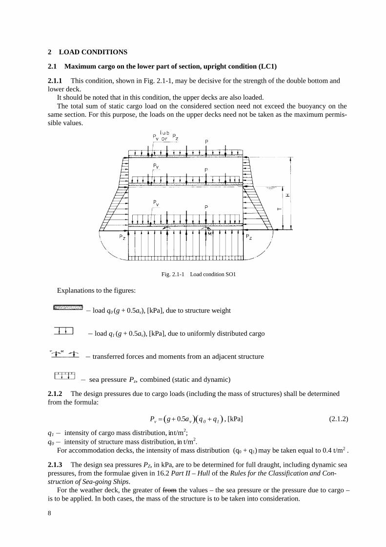
2.1 Maximum cargo on the lower part of section, upright condition (LC1)
2.1.1 This condition, shown in Fig. 2.1-1, may be decisive for the strength of the double bottom and lower deck.
It should be noted that in this condition, the upper decks are also loaded. The total sum of static cargo load on the considered section need not exceed the buoyancy on the
same section. For this purpose, the loads on the upper decks need not be taken as the maximum permis-sible values.
Fig. 2.1-1 Load condition SO1
Explanations to the figures:
− load q0 (g + 0.5av), [kPa], due to structure weight
− load q1 (g + 0.5av), [kPa], due to uniformly distributed cargo
− transferred forces and moments from an adjacent structure
− sea pressure Pz, combined (static and dynamic)
2.1.2 The design pressures due to cargo loads (including the mass of structures) shall be determined from the formula:
Pv = (g + 0.5a v )(q 0 + q1 ) , [kPa] (2.1.2)
q1 − intensity of cargo mass distribution, in t/m2; q0 − intensity of structure mass distribution, in t/m2.
For accommodation decks, the intensity of mass distribution (q0 + q1) may be taken equal to 0.4 t/m2 .
2.1.3 The design sea pressures PZ, in kPa, are to be determined for full draught, including dynamic sea pressures, from the formulae given in 16.2 Part II – Hull of the Rules for the Classification and Con-struction of Sea-going Ships.
For the weather deck, the greater of from the values – the sea pressure or the pressure due to cargo – is to be applied. In both cases, the mass of the structure is to be taken into consideration.

9
2.2 Maximum cargo on the lower part of section, heeled condition (SO2)
2.2.1 This condition, shown in Fig. 2.2-1, may be decisive for the strength of the bottom, sides, pillars between decks and lower decks.
The cargo distribution on the considered section is to be the same as for load condition SO1. Symbols are adopted according to Fig. 2.1-1.
Fig.2.2-1 Load condition SO2
2.2.2 The design pressures due to cargo (including the mass of structures) are to be assumed as acting at an oblique angle to the deck.
The pressure components in the ship’s vertical direction (according to the hull co-ordinate system) are to be taken as:
Pv = g(q 0 + q1 ), [kPa] (2.2.2-1)
The pressure components in the ship's transverse direction (according to the hull co-ordinate system) are to be taken as:
Pt = 0.67a T (q 0 + q1 ) , [kPa] (2.2.2-2)
q0, q1 − as defined in 2.1.2. In the case of different cargo loads in specified areas, the mean value of q1 for the whole deck area
may be applied. Where movable decks for the carriage of vehicles are used, the pressure components (in the ship’s
transverse direction) due to the mass of vehicles and their cargo, determined in accordance with 2.2.2-2, are to be taken into consideration and are to be applied in accordance with real conditions of the decks supports.
2.2.3 The design sea pressures are to be determined for full draught, corrected for the effects of wave form and roll.
The pressure at the bilge for the emerged side is to be determined from the formula:
10 5 tg2
AZP T B Φ
= − ⋅ [kPa] (2.2.3-1)
For the position T – 0.5B · tg 2AΦ
[m], above the baseline, PZ = 0 is to be taken. The pressure at bilge for the submerged side is to be determined from the formula:

10
10 3,3 tg2
AZP T B Φ
= + ⋅ [kPa] (2.2.3-2)
For the position T + 0.33B ⋅ tg 2AΦ
[m], above the baseline, PZ = 0 is to be taken.
Between the positions specified above, the value of PZ is to be varied linearly. If, at the above-specified pressure distribution, the weather deck is partially submerged, then the sea
pressure on the weather deck may be disregarded when cargo loads are applied.
2.3 Maximum cargo on the upper part of section, upright condition (SO3)
2.3.1 This condition, shown in Fig. 2.3-1, may be decisive for the strength of double bottom and high-er decks.
All cargo spaces, except those above the double bottom, are to be considered loaded to the maxi-mum.
If the total sum of static cargo loads exceeds the buoyancy on the same section, the loads on lower decks may be reduced. If this condition is unrealistic for stability reasons, adjustments to this condition are to be made and submitted for consideration.
2.3.2 The design pressures due to cargo and design sea pressures are to be calculated as for SO1 condi-tion.
Symbols are taken according to Fig. 2.1-1.
Fig. 2.3-1 Load condition SO3
2.4 Maximum cargo on the upper part of section, heeled condition (SO4)
2.4.1 This condition, shown in Fig. 2.4-1, may be decisive for the strength of the double bottom, high-er decks, pillars between decks, as well as the strength of the ship sides. The cargo distribution on the section is to be the same as for SO2 condition.
Symbols are taken according to Fig. 2.1-1.

11
Fig. 2.4-1 Load condition SO4
2.4.2 The design pressures due to cargo and design sea pressures are to be calculated as for SO2 condi-tion.
2.5 Ballast condition (SO5)
2.5.1 This condition, shown in Fig. 2.5-1, may be decisive for the strength of the double bottom in ships with pillars supporting decks.
The design pressures due to the mass of deck or double bottom structures are to be calculated as for SO1 condition. For the decks, the value of q1 is to be taken as zero. Double bottom tanks for bunker are to be considered empty. Ballast shall be placed in double bottom tanks.
Symbols are taken according to Fig.2.1-1.
Fig. 2.5-1 Load condition SO5
2.5.2 Design bottom pressure PZ, in kPa, is to be determined, taking into consideration dynamic com-ponents. Pressures dynamic components are to be determined from the formulae given in Part II – Hull, of the PRS Rules, substituting to them draught T. Static pressures are to be determined for draught Tb.
At position h = T b + 0.1PTb above the baseline, PZ = 0 is to be taken. PTb denotes PZ at z = Tb (z = 0 is to be taken at the baseline).
Linear variability of the pressures is to be taken along the ship side, between levels z = Tb and z = h (Fig.2.5-1).

12
2.6 Transversely unsymmetric deck load (SO6)
2.6.1 This condition, shown in Fig. 2.6-1, is applicable only to strength analysis of deck grillage sup-ported by pillars.
Fig. 2.6-1 Load condition SO6
2.6.2 The loads are to be calculated as for SO1 condition.
2.7 Longitudinally unsymmetric deck load (SO7)
2.7.1 This condition, shown in Fig. 2.7-1, is applicable only to strength analysis of deck grillage sup-ported by pillars.
Fig.2.7-1 Load condition SO7
2.7.2 The loads are to be calculated as for SO1 condition.
2.8 Deck loaded with concentrated forces (SO8)
2.8.1 This condition is applicable only to strength analysis of deck grillage (or to the transverse plane framework) to allow for concentrated forces from a pile of containers or from other cargo.
2.8.2 Loads are to be calculated for the maximum permissible mass of pile of containers and the mass of the structure, including vertical accelerations calculated in accordance with 2.1.2.

13
3 MODELLING OF STRUCTURE
3.1 General
3.1.1 For structures where the transverse strength members are supported only at the ship sides, one model of the transverse web frame structure will be sufficient.
3.1.2 If the deck and the double bottom are designed with pillars and longitudinal girders in addition to the transverse web frames, force distribution from an the adjacent structure to the transverse web frame in question is to be considered. This can normally be calculated by 2-dimensional grillage models.
3.1.3 The correlation between forces and displacements in the individual 2-dimensional grillage mod-els is to be satisfactory. Symbols used in the description of the models are given in Fig. 3.1-1.
Rys.3.1-1 Symbols used in schemes of structure calculation models
3.1.4 Structures in the way of openings for ramps, lifts, etc., may be analysed on the basis of modified 2-dimensional models. Necessary modifications will be considered in each particular case.
element (bar) between nodes
rigid end of element
rigid element
element with symmetry conditions at end (grillage model)
fixed node node with vertical support (grillage model)
node with pillar support (grillage model)
node with linear in plane restraint (linear spring able to be displaced in gril-lage or framework plane)

14
3.2 Transverse web frames
3.2.1 Figs. 3.2-1 and 3.2-2 show typical models of a transverse web frame at pillars and between pil-lars when centreline pillars are fitted. The model is to extend from side to side to allow for unsymmetric load conditions.
Fig.3.2-1 Transverse web frame at pillars
Fig.3.2-2 Transverse web frame between pillars
3.2.2 Vertical and horizontal supporting springs corresponding to the stiffness of ship's sides and decks are to be applied.
For transverse web frames in the mid-part of hull compartment of length l specified below, the stiff-ness coefficients for spring pillars A, B, C, D and E may be calculated from the formula:
2 2
0,55 2,6
384 8r S
EKl lS I A
⋅=
⋅+ ⋅ ⋅
(3.2.2-1)
l − distance between effective transverse bulkheads; the value l, taken for calculations, is not to be greater than 0.9 L;
Sr − transverse web frames spacing; I − actual moment of inertia of that part of hull cross-section, within mid-part of hull compartment
of length l, which acts as the spring support: ship side (spring A) and deck or bottom (springs B, C, D, E), calculated against the neutral bending axis, taking into account effective strake areas (parts of decks and bottom cross sections – for spring A and those of side structures and longitu-dinal bulkheads – for springs B, C, D, E).

15
As − actual shear area of that part of hull cross-section, within mid-part of hull compartment of length l, which acts as the spring support: of ship's side and longitudinal bulkhead (if any) (spring A) and of bottom or deck (springs B, C, D, E).
For frames situated outside the mid-part of hull compartment of length l, the stiffness coefficients K, defined as above, may be calculated from the below formula:
𝐾𝐾 = 0,5·𝐸𝐸·𝐼𝐼·𝑆𝑆𝑟𝑟
𝑙𝑙4� 124𝑥𝑥𝑙𝑙−
112�
𝑥𝑥𝑙𝑙�3+ 124�
𝑥𝑥𝑙𝑙�4�+2,6 𝐼𝐼
𝐴𝐴𝑠𝑠𝑙𝑙2�12 𝑥𝑥𝑙𝑙 − 12�
𝑥𝑥𝑙𝑙�2� (3.2.2-2)
where: x – distance to the fore fore-end of hull compartment of length l; other symbols are defined as in formu-
la 3.2.2-1.
3.2.3 Transverse web frames between pillars are normally connected to the pillar by a longitudinal centre plane deck girder. In 2-dimensional model, this connection may be represented by springs F, G, H and I. The stiffness coefficient of these springs may be calculated from the formula:
3
12,6
384 8 S
EKl lnk
I A
=
+ ⋅ ⋅
(3.2.3-1)
l − distance between pillars; I − actual moment of inertia of the girder; As − transverse (shear) section of the girder; n − number of transverse web frames between pillars; kl − factor determined from Table 3.2.2.
Table 3.2.2
n 1 2 3 4 5 6 7 8 9 10 >10
k1 2.00 1.50 1.33 1.25 1.20 1.18 1.14 1.12 1.11 1.10 1.0
If spring supports are not available in the software used, the spring may be replaced by a “spring ele-ment” with cross-sectional area:
SKlAE
= (3.2.3-2)
ls − length of “spring element”.
3.3 Deck and bottom structures
3.3.1 A typical deck design and corresponding model are shown in Fig. 3.3.1. This model may be used for the analysis of load conditions SO6 and SO7. In addition, the force distribution in the deck or bottom longitudinal girders may be determined for load conditions SO1 - SO5 and applied to the transverse web frame model given in Fig. 3.2-1. This applies when pillars are used to support the deck and bottom struc-ture. The compatibility of forces and displacements at the intersections between the web frame and gril-lage models may be difficult to obtain when the number of longitudinal girders is large. In this case, it may be more convenient (or necessary) to apply a 3-dimensional model combining web frame models and grillage models.
16
a) Typical deck structure (transverse section)
b) Grillage model (upper deck), including ship sides unfolded
Fig. 3.3-1 Deck structure
Fig.3.3-2 Deflections of transverse web frame under angle of heel
Pre-set displacement of boundary nodes in grillage model
Rys 3.3-3 Racking
The grillage model of deck structure for load condition SO8 (in some cases 2-dimensional model may be sufficient) is to include such part of the deck area, which would adequately represent the heterogeneity of loads and the symmetry of the structure.
3.3.2 The node supported by a pillar is to be given rotational spring stiffness in x- and y- direction, calculated from the formula:
3,9
4
r
S
EK lI A l
=+
, moment unit/rad (3.3.2.)
l − length of a pillar; I − relevant moment of inertia of pillar (in x- or y- direction); As − relevant shear area of a pillar (in x- or y- direction).
It should be noted that for tween decks, the value of Kr is to be taken as the sum of stiffness of pil-lars above and below the deck considered.

17
3.3.3 The node supported by a pillar in each grillage model is to be given pre-set vertical displacement corresponding to the deflection (relative displacement) obtained in the successive transverse web frame calculation.
For the loading conditions SO2 and SO4, the transverse boundary nodes of grillage are to be given similar pre-set displacement corresponding to the deflections due to racking between the decks (see Fig. 3.3-3).
4 STRESS ANALYSIS
4.1 General
4.1.1 Permissible girder stresses given in Part II – Hull of the Rules, Section 14.4, are to be complied with.
4.1.2 The stability factor (usage factor) η of pillars is to comply with: 0,7
1
a
c li
ση
σ= ≤
+(4.1.2)
where:
0,7 0,31 l
i
≥+
σa − calculated compressive stress;σc − critical buckling stress of pillar; it may be calculated according to 13.7, Part II – Hull of the Rules;l − length of pillar, in m;i − radius of gyration, in cm.
4.1.3 The stability factor (usage factor) for plating acting as girder flange is to comply with:
0,87a
c
ση
σ= ≤ (4.1.3)
σa and σc − see 4.1.2.
4.2 Strength of cross joints
4.2.1 The flange discontinuity at cross joints of highly stressed girders is to be normally compensated by brackets. If brackets are not possible, e.g. between deck transverse and ship's side vertical girders, high shear stresses in the web area combining the girders may occur.
The design shear stress may normally be taken as the average of stresses calculated from the formula:
1 2
2
10 m s
s
P QtA−
= , [MPa] (4.2.1-1)
and
2 1
1
10 m s
s
P QtA−
= , [MPa] (4.2.1-2)

18
Fig.4.2-1 Stress analysis of cross joint
Qs − shear force at girder web, in kN; Pm − longitudinal force in girder flange, in kN; As − girder shear area, in cm2.

19
5 STRESS ANALYSIS WITH FE MODEL OF THE WHOLE SHIP HULL
5.1 Analysis purpose and scope
5.1.1 The analysis performed in accordance with the requirements of this Chapter is aimed mainly at the assessment of stress level in the transverse web frame system made by deck transverses, web frames and divisions (or partial bulkheads), which compensates transverse cargo loads in heeled conditions (so-called racking) – see also 1.2.1.
For that purpose, the use of the FE model of the whole ship hull is required, in accordance with the requirements of 5.2 and 5.3.
5.1.2 The FEM calculations with the whole ship hull may also be required by PRS for the assessment of capacity and strength of „ro-pax” ships superstructure, in general bending conditions (see 5.2.3 and 5.3.3), and the strength of the primary supporting member system of decks, sides and pillars, instead of calculations with grillage and framework models, as defined in Chapter 3 (see 5.2.2 and 5.3.2).
5.2 Finite elements in FE model of the whole ship hull
5.2.1 FE model for strength analysis for ship in heeled condition (racking)
5.2.1.1 It is recommended to apply the FE model of the whole ship hull with the use of plate finite elements for modelling plating (decks, sides, bulkheads, etc.) and frame webs. T-beam flanges may be modelled by the bar or beam finite elements. Plating stiffeners shall be modelled with the use of beam elements, taking into account eccentricity of stiffener cross-section centre of gravity in relation to the plating. General modelling principles (type, size and elongation of finite elements, method of considering openings/cutouts in primary supporting member webs, modelling brackets, etc.) shall be applied in ac-cordance with paragraph 14.4.2 of the Rules for the Classification and Construction of Sea-going Ships, Part II – Hull.
Such finite element mesh will be further defined as a standard mesh.
5.2.1.2 An example division into finite elements of a part of the ro-ro ship hull structure (standard fi-nite element mesh) is shown in Fig. 5.2-1.

20
Fig. 5.2-1 Example of the standard mesh
5.2.1.3 Alternatively, the FE model of the ship hull may include areas modelled with the standard mesh (see 5.2.1.1) and those modelled with elements of bigger size (i.e. with the use of the so-called „coarse mesh”).
The use of standard FE mesh (acc. to 5.2.1.1) is obligatory for the midship part (for the length not less than ship’s breadth B), and the FE model shall take into account hatch openings in decks for transfer of vehicles between cargo decks.
Depending on the space spatial arrangement of the ship, PRS may require the application of standard FE mesh also in other hull regions (e.g. at ship ends, where stern doors/ramps or watertight doors in col-lision bulkhead are installed).
In regions with coarse modelling, the requirements of 14.6.2.3 of the Rules for the Classification and Construction of Sea-going Ships, Part II – Hull, are to be applied.
The above means that the plating may be modelled by plate elements of edge length equal to web frame spacing in the longitudinal direction and transversely to longitudinal girders spacing, however not longer than 1.5 web frame spacing.
Plating stiffeners in this region may be concentrated (a few pieces at a time) and located along the edge of plate elements.
The girder webs may be modelled by one row of finite elements (along with the member depth) and their flanges – by bar or beam elements.
Small openings in the primary supporting member webs may be generally disregarded in the FE mod-el. Passage openings may be taken into account by the use of equivalent thickness of the web.
Sufficient transition zones, divided into finite elements to allow for a smooth transition from standard to coarse mesh, shall be provided between the modelled region using standard mesh (according to 5.2.1.1.) and the regions with coarse mesh applied.
The above method of (example) hull division into finite elements is shown in Fig. 5.2-2. The fig-ure shows only a part of the ship bottom and side.

21
Fig. 5.2-2 Regions of hull sides and bottom modelled with the use of standard mesh and coarse mesh
Note: the level of stresses calculated with the use of FEM, in ship heeled condition (”racking”) is assessed in accordance with requirements of 5.4.1 only in the regions where standard FE mesh is applied in the FE model.
5.2.2 FE model for strength analysis of primary supporting members of decks, sides and pillars (upright ship)
5.2.2.1 The FE model with standard FE mesh (see 5.2.1.1) may be applied for the analysis of load cas-es required in Chapter 2, which formally concern framework and grillage FE models required for an up-right ship (loading conditions SO1, SO3, SO5, SO6, SO7, SO8).
The FE model for the assessment of structural strength in regions indicated in Chapter 2 may be a part of the FE model of the whole hull.
Alternatively, a model may be applied of hull part situated between frame sections spaced on each side from the region where the stress level is assessed by a distance not less than the region length.
Loading of FE model shall comply with the requirements of 5.3.2, and the stress level shall be as-sessed to criteria defined in 5.4.2.
5.2.3 FE model for hull general strength analysis
5.2.3.1 FE model with standard FE mesh, as defined in 5.2.1.1, may be used for the general strength analysis of the ship, using loading defined in 5.3.3. The assessment of the level of calculated stresses is performed according to 5.4.3.
5.2.3.2 The analysis of general strength may use the FE model with a „coarse” mesh of finite elements, defined in 5.2.1.2.
The loading defined in 5.3.3 shall then be applied. The level of calculated stresses is assessed in ac-cordance with 5.4.3.
5.2.3.3 In the way of superstructure situated in the midship part, the FE model shall consider openings for doors and windows.

22
If many window openings are situated close to each other, fragments of superstructure walls be-tween neighbouring windows shall be modelled with finite fine elements. In such a case, it is sufficient to use at least one row of finite elements between the windows, unless the spacing of windows edges is greater than the length of sides of plate elements required for standard FE mesh (see 5.2.1.1). In this case, vertical and horizontal stiffenings of walls shall be considered, with at least the use of beam elements with their neutral sectional axis displaced from the plating. In the FE model, the position of the stiffen-ings may be slightly changed to have them situated on the edges of plate elements, that model wall plat-ing.
In the way of steps (ends of side or internal walls) of the superstructure or deckhouse and in the re-gion of expected greatest stresses at the edges of window openings, PRS may additionally require the application of locally more dense FE mesh of squares not larger than 50 x 50 mm, in order to reflect with sufficient accuracy the shape of opening corners (see the requirements for local FE models given in 14.7 of the Rules for the Classification and Construction of Sea-going Ships, Part II – Hull).
The level of stresses determined in regions where such more dense FE mesh has been applied shall be assessed according to the requirements of 5.4.3.2 or 5.4.3.3.
An example fragment of the FE model in the region of windows is shown in Figs. 5.2-1 and 5.2-2.
Fig.5.2-3 Example application of standard FE mesh in the region of openings for windows or doors

23
Fig. 5.2-4 An example of more dense FE mesh in the region of a window
5.3 Loads and supports
5.3.1 Strength analyses in the ship heeled condition („racking”)
5.3.1.1 For particular transverse sections, loads required for load conditions SO2 and SO4 (see Chapter 2) are to be assumed.
Maximum local load value (pressure of uniformly distributed cargo or load due to vehicles, cargo trays, etc.) shall be applied, according to ship design and Loading Manual of the ship.
If the load due to cargo on loaded decks or internal bottom, in SO2 or SO4 condition, distributed along the whole length of the ship cargo space, exceeds the value corresponding to the ship capacity, the non-loaded deck segments having an appropriate length and situated possibly symmetrically against the loaded midship region shall be located in regions of bow and stern.
5.3.1.2 The FE model of the whole ship hull shall be approximately balanced. The model shall may be balanced through the application, to ship sides and bottom, continuous loads
qy, qz and qM (in [N/m]), which can compensate hull internal loads and external loads (water pressure) – see Fig. 5.3-1.
During development of the FE model, in order to determine the values of loads qy, qz and qM , the hull shall be divided longitudinally into at least 20 segments of similar length, and the internal and exter-nal loads shall be applied so that they are sectionalized to successive segments.
Subsequently, the load within each segment shall be reduced, e.g. to a point at the ship bottom, in the centre plane, in the middle of segment length, to achieve forces Py, Pz and torque Mx (Fig.5.3-1).
Continuous load qy evenly distributed along the segment length balances the force Py, continuous loads qz balance the force Pz and continuous loads qM balance the torque Mx.
It is recommended to apply continuous loads qz and qM along the lines determined by points A1 and A2, i.e. in the middle of the side section between the internal bottom and the lowest deck (Fig. 5.3-1).

24
Fig.5.3-1 Balance method for FE model of the whole ship hull
5.3.1.3 PRS may accept another method of FE model balancing, than the one presented in 5.3.1.2, up-on the proposal of ship designers, if the method does not result in determining inaccurate values of hull structure stresses.
5.3.1.4 The model with a balanced load according to the requirements of 5.3.1.2 shall be properly sup-ported. Possible option for non-displaced supports assumes zero values of displacements ux , uy or uz in some nodes of the FE model in x, y, z directions of the ship coordinate system (Fig. 5.3-2).
Zero values of displacements: 𝑢𝑢𝑦𝑦 = 0, 𝑢𝑢𝑧𝑧 = 0 − in point (node) A1 (at the bottom, in aft region); 𝑢𝑢𝑥𝑥 = 0 , 𝑢𝑢𝑦𝑦 = 0, 𝑢𝑢𝑧𝑧 = 0 − in point B (at the bottom, in the centre plane, in bow region); 𝑢𝑢𝑧𝑧 = 0 − in point A2 (at the bottom, in aft region).
Points A1 and A2 are arranged symmetrically against the symmetry plane. The rotation angles of nodes in the FE model in points A1, A2 and B are not to be restricted.
Fig. 5.3-2 Fixed supports in FE model of the whole ship hull

25
5.3.2 Strength analyses of primary supporting members of decks, sides and pillars (upright ship)
5.3.2.1 The FEM analysis shall consider loads defined in Chapter 2 (other than in load conditions S02 and SO4, covered by 5.3.1).
5.3.2.2 The ship hull region where the strength of the primary supporting member system is analyzed, shall be modelled with the use of standard FE mesh (see 5.2.1.1). Other hull regions may be modelled with the use of coarse FE mesh (see 5.2.1.2).
If the FE model includes coarse modelled regions, the stress analysis made in accordance with 5.4.2 covers fragments of a structure modelled with the standard mesh, spaced at least 0.5B (B – ship’s breadth) from the segments with coarse modelling.
5.3.2.3 Alternatively, the FE model may be a hull segment being a part of full-length ship model (not less than required in Chapter 2 and not less than 2B, where B is the ship’s breadth), which includes struc-ture extending between the bottom and the uppermost deck.
The stress analysis made according to 5.4.2 covers the structure region situated at least 0.5B from the segment ends.
5.3.2.4 In stress calculations of the primary supporting member system (FE models), the effect of gen-eral bending on stress level in longitudinal girders may be disregarded, by the assumption that the ship sides at the internal bottom are supported in the vertical direction (𝑢𝑢𝑧𝑧 = 0 and displacements related to the other five degrees of freedom of nodes are not restricted – see displacement symbols referred to in 5.3.1.4).
Additionally, the support 𝑢𝑢𝑦𝑦 = 0 shall be applied in two points at the ends of the hull model or hull segment model, in the symmetry plane, at the ship bottom. Displacements related to the other five de-grees of freedom of the FEM nodes are not restricted, except the application of an additional support 𝑢𝑢𝑥𝑥 = 0 at one of the above two nodes.
Normal stresses due to general bending may be determined with the use of the whole ship (beam model) or by general bending analysis made according to the requirements of 5.3.3, and subsequently added to the stresses calculated by FEM in accordance with this paragraph 5.3.2 (see also 14.5.3 and 15.1.1.2 of the Rules for the Classification and Construction of Sea-going Ships, Part II – Hull).
5.3.3 Hull general strength analysis
5.3.3.1 In the FE model defined in 5.2.3, the load shall be applied, which will approximately ensure along ship’s hull the value of bending moment required in Chapter 15 of the Rules for the Classification and Construction of Sea-going Ships, Part II – Hull, used there to determine the required hull section modulus (combined still water bending moment Ms and wave bending moment Mw).
It is particularly important to achieve a possibly precise value of Ms + Mw in the midship part of the hull.
In this case, local loads (the own weight of structure weight, external pressures and cargo/stores loads) are not directly considered, however, appropriately chosen continuous load similar to the load qz, used in accordance with 5.3.1.2, shall be applied along the ship sides.
In this case, the condition of zero value of total vertical ship load due to loads qz shall by fulfilled. The transverse (shear) force in the hull shall not cause excessive values of permissible shear stresses in shell plating, according to criteria defined in Chapter 15 of the Rules for the Classification and Construc-tion of Sea-going Ships, Part II – Hull.
5.3.3.2 The ship hull shall be supported as defined in 5.3.1.4.
5.3.3.3 PRS may accept methods of loading and supporting the FE model proposed by hull designers, which are alternative to those defined in 5.3.3.1 and 5.3.3.2, provided the accuracy of calculated normal stresses due to general bending is found sufficient.
26
5.4 Stress analysis
5.4.1 Ship in heeled condition („racking”)
5.4.1.1 For the regions of the FE model subjected to stress analysis, where standard FE mesh has been applied (see 5.2.1.1 and 5.3.1), the strength criteria defined in 14.5.3.1 of the Rules for the Classification and Construction of Sea-going Ships, Part II – Hull shall be fulfilled.
In this case, checking the level of normal stresses in longitudinal girders, including hull general bend-ing stresses, according to 14.5.3.2 of the Rules for the Classification and Construction of Sea-going Ships, Part II – Hull, is not obligatory.
5.4.2 Strength analysis of the primary supporting members of decks, sides and pillars
5.4.2.1 The analysis covers the stress level in regions modelled with the use of standard FE mesh (see 5.2.1.1), according to 5.3.2.
For the stresses calculated without considering hull general bending stresses (see 5.3.2.4), the strength criteria defined in 14.5.3.1 of the Rules for the Classification and Construction of Sea-going Ships, Part II – Hull are obligatory.
For longitudinal girders, criteria for normal stresses considering hull general bending stresses defined in 14.5.3.2 of the Rules for the Classification and Construction of Sea-going Ships, Part II – Hull shall be additionally fulfilled. The calculation method of the stresses is defined in 5.3.2.4.
5.4.3 Hull general strength analysis
5.4.3.1 The analysis covers the level of normal stresses (along ship axes) in deck and bottom plating modelled for FEM analysis in accordance with the requirements of 5.2.3 and loaded in accordance with the requirements of 5.3.3.
The average normal (membrane) stresses in plate elements situated in areas corresponding to required sizes of plate elements of a coarse mesh (defined in 5.2.1.2) are not to exceed 175k, MPa (k – strength coefficient of used steel – see 2.2.1.2 of the Rules for the Classification and Construction of Sea-going Ships, Part II – Hull).
5.4.3.2 In the way of steps (ends) of sidewalls of superstructure or deckhouse and in way of doors and windows in those walls, where PRS may require the application of more dense FE mesh (see 5.2.3.3), the permissible level of membrane equivalent stresses in the centres of plate elements having dimensions not more than 50 mm x 50 mm and of main stresses at the edges of the opening, amounts to 310k, MPa – see 14.7.2.4 of the Rules for the Classification and Construction of Sea-going Ships, Part II – Hull.
5.4.3.3 If a more dense FE mesh is used for the fatigue strength assessment of structure in stress con-centration areas referred to in 5.4.3.2, in accordance with the requirements of PRS Publication 45/P – Fatigue Strength Analysis of Steel Hull Structure (plate elements of side length approximately equal to the plate thickness), the assessment covers average stresses in the areas od approximate size 50 mm x 50 mm (see 14.7.2.4 of the Rules for the Classification and Construction of Sea-going Ships, Part II – Hull).
List of amendments effective as of 1 April 2021
Item Title/Subject Source 5 Stress Analysis with FE Model of the Whole Ship Hull PRS R&B