Embed Size (px)
Citation preview

JUl 1 5 1qq1 PUBLIC SERVICE COMPANY OF NEW MEXICO
ALVARADO SQUARE ALBUQUERQUE, NEW MEXICO 87158
Certified Mail Return Receipt Requested
Mr. Rich Mayer Environmental Protection Agency 1445 Ross Avenue, Suite 1200 Dallas, Texas 75202-2733
Dear Mr. Mayer
July 09, 1991
Subject: Proposed Remediation Workplan, Natural Pit SWMU, Person Generating Station, NMT360010342
Public Service Company of New Mexico (PNM) is seeking approval from EPA to excavate and remove contaminated soil from the Solid Waste Management Unit (SWMU) identified in RCRA permit NMT360010342 as the "Natural Pit".
PNM is hereby submitting a proposed RCRA Facility Investigation (RFI) Remediation Work Plan for the Natural Pit and is requesting approval from EPA to conduct this activity. The enclosed remediation plan follows the format of previous work plans submitted to you for the original Natural Pit RFI. Additionally, this work plan references those previous plans and their subsequent reports of findings.
If you have any questions, or need additional information, please contact me at (505) 848-2998.
Sincerely,
Ron D. Johnson Sr. Environmental Scientist
RDJ:vrm
enclosure: RFI Remediation Work Plan Person Generating Station Natural Pit Area, NMT360010342
cc: Ed Horst, New Mexico Env1ronment Department
enclo5u.re )/{)7 Fo/)J')d

RCRA Facility Investigation (RFI) Remediation Work Plan
For Person Generating Station Hazardous Waste Disposal Facility - Natural Pit Area
(NMT360010342)
July 1991 ~ 81 ti __ LLzt t\
JUL 1 5 1qq1

TABLE OF CONTENTS
Chapter and Description Page
1.0 Introduction and Background 1 2.0 Person Station Demolition Project 2 3.0 Natural Pit Work scope overview 3 4.0 Natural Pit Remediation Work Scope 4
4.1 Heavy Metal Contamination 4 4.2 Fuel Oil Contamination 5
5.0 Quality Assurance I Quality Control (QA/QC) Procedures 6 5.1 sample custody 6 5.2 Sampling Procedures 6 5.3 Replicates 6 5.4 Analytical Procedures 7
6.0 Data Management Procedures 9 6.1 Data Collection 9 6.2 Data Management 9 6.3 Data Presentation 6.4 Statistical Treatment of Data
7.0 Health and Safety Procedures
Appendices
Map 1 - Natural Pit Area - Remediation sampling Plan
Exhibit 1 - Chain of custody Form
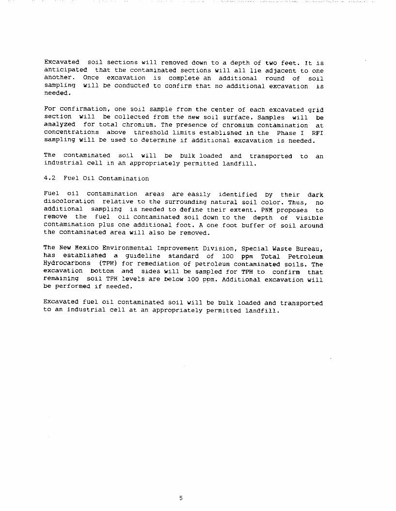
Exhibit 2 - Sample Log Form
Exhibit 3 - Site Health and Safety Plan
9 9
11

1.0 Introduction and Background
In 1988 the Environmental Protection Agency (EPA) issued a hazardous waste permit (NMT360010342-l) pursuant to its authority under the Hazardous and Solid Waste Amendments of 1984 for the Person Gene~rating Station. That permit identified the Natural Pit at Person Station as a Solid Waste Management Unit (SWMU) requiring investigation for release of hazardous constituents to the environment.
In March 1989, Public service Company of New Mexico (PNM), submit:ted to EPA a RCRA Facility Investigation (RFI) Work Plan for the Natural Pit area at Person Generating Station. That work plan detailed methoCls and procedures used by PNM in the investigation of potential releases of contaminants into the environment from the Natural Pit.
Final work plan approval from EPA was issued in July 1989. Field sampling under the work plan was conducted in August 1989. Result.s from the Phase I sampling confirmed the presence of visual fuel oil contamination in two areas of the Natural Pit. The Phase I sampling also revealed the presence of chromium, lead, and arsenic contaminati.on in the upper two feet of the soil at one location within the Natural Pit.
After review of the results contained in the document "RFI Report of Findings", January 18, 1990, EPA requested additional soil bore sampling for heavy metal contamination in proximity to the location where the heavy metals were discovered in the Phase I sampling. This Phase II sampling was conducted in June 1990.
The Phase II sampling results confirmed ~he presence of chromium, lead, and arsenic contaminants above background levels. The contamination again was only seen in the upper two feet of the soil.
The heavy metal contaminatio'~ appeared to be confined to a central area within the Natural Pit and was not migrating out of the pit (no contamination was found down slope from the contaminated areas). This information was supplied to EPA in the document "RFI Report of Findings, Phase II", August 28, 1990. After reviewing the report results EPA notified PNM that no remedial action was necessary. PNM was required to file a survey plat with the local deed authority specifying the location and contents of the Natural Pit, and was required to post warning signs around the Natural Pit.
l

2.0 Person Station Demolition Project
In 1991, PNM management decided that Person Generating Station would not be restarted and that opportunities for sale or salvage of plant equipment should be investigated. Additionally, certain environmental issues associated with the property were to be addressed and remediated, if needed.
The contamination in the Natural Pit was identified as an area which would be remediated under this project. Because the Natural Pit is a SWMU associated with the Person Station Hazardous Waste Disposal Permit it was recognized by PNM that remediation of the Natural Pit would require prior approval from EPA.
This document is the remediation work plan for the Natural Pit submitted to EPA for their consideration and approval.
2

3.0 Work Scope overview
Phase I and Phase II sampling indicated that the heavy metal contamination is localized within the Natural Pit to a central area and down to a depth of two feet. This remediation work plan proposes a grid sampling scheme to specifically identify the exact location and the horizontal extent of the heavy metal contamination. Once identifiE!d, the contaminated soil will be removed to an industrial cell at an appropriately permitted landfill for disposal. Post removal soil sampling will be conducted to verify that the contaminated soil has been removed.
The Phase I sampling also verified visual evidence of fuel oil contaminated soil within the Natural Pit. Since the fuel oil contamination and the heavy metal contamination are unrelated to each other, remediation of the fuel oil contamination will be performed differently.
Fuel oil contaminated soil will be removed based on visual observation of contaminated areas. Removed soil will be placed into an industrial cell of an appropriately permitted landfill. Post removal soil sa,mpling will be conducted to verify that the contaminated soil has been removed.

4.0 Work Scope
4.1 Heavy Metal Contamination
An approximate 2600 square feet area of the Natural Pit will be grided at 5 foot intervals. The grided area will encompass all sample locations found to contain heavy metal contamination during Phase I and Phase II sampling. At each grid line intersection a stake will be placed to mark the location for subsequent soil sampling. Grid intersections will be identified using an alphanumeric numbering scheme. North-south grid lines will be alphabetic, east-west grid lines will be numerical. A grid intersection will be identified by its intersecting grid lines, e.g., "C-4". Map l in the Appendix shows the general contour of the Natural Pit and illustrates how the Natural Pit will be grided for sampling.
Soil samples will be collected from the 0-1 foot depth interval using a hand augering soil sampler. Samples will be analyzed for total chromium only as an indicator of heavy metal contamination. The presence of chromium contamination at concentrations above threshold limits established in the Phase I RFI sampling will be used to determine if an adjacent 5 foot by 5 foot soil section will need to be excavated.
If a grided soil section has four surrounding samples which do not show elevated levels of chromium, that section will be considered clean and will not be excavated. Figure 4.1 is an example showing several grided sections. An "X" at the intersection indicates a soil sample with chromium levels above background thresholds, a "0" at the intersection indicates a soil sample with chromium levels at background. The figure also shows which grid section will be excavated down to two feet based on the sample results shown.
Figure 4.1 Excavation Scheme for Heavy Metal Contamination
C D E F G H 3 o----------0----------o----------o----------o----------o
4 0----------o----------o----------o----------o----------o ! Excavate ! Excavate ! Excavate ! Excavate !
5 o----------x----------x----------x----------0----------o ! Excavate ! Excavate ! Excavate ! Excavate !
6 o----------o----------0----------x----------o----------o ! Excavate ! Excavate !
7 o----------o----------o----------o----------0----------o "X" = Chromium above background threshold levels "0" = Chromium at background levels
..j.
Excavated soil sections will removed down to a depth of two feet. It is anticipated that the contaminated sections will all lie adjacent to one another. Once excavation is complete an additional round of soil sampling will be conducted to confirm that no additional excavation is needed.
For confirmation, one soil sample from the center of each excavated grid section will be collected from the new soil surface. Samples will be analyzed for total chromium. The presence of chromium contamination at concentrations above threshold limits established in the Phase I RFI sampling will be used to determine if addit~onal excavation is needed.
The contaminated soil will be bulk loaded and transported to an industrial cell in an appropriately permitted landfill.
4.2 Fuel Oil Contamination
Fuel oil contamination areas are easily identified by their dark discoloration relative to the surrounding natural soil color. Thus, no additional sampling is needed to define their extent. PNM proposes to remove the fuel oil contaminated soil down to the depth of visible contamination plus one additional foot. A one foot buffer of soil around the contaminated area will also be removed.
The New Mexico Environmental Improvement Division, Special Waste Bureau, has established a guideline standard of 100 ppm Total Petroleum Hydrocarbons (TPH) for remediation of petroleum contaminated soils. The excavation bottom and sides will be sampled for TPH to confirm that remaining soil TPH levels are below 100 ppm. Additional excavation will be performed if needed.
Excavated fuel oil contaminated soil will be bulk loaded and transported to an industrial cell at an appropriately permitted landfill.
5

5.0 Quality Assurance I Quality Control (QA/QC) Procedures
The QA/QC procedures described here apply primarilY to the proposed grid sampling for chromium, though good QA/QC practices will also be employed for collection and analysis of TPH samples for verification of the fuel oil contamination remediation.
5.1 Sample Custody
Sample Exhibit document
custody will be documented using chain-of-custody forms shown in 1 of this work plan. The chain-of-custody forms will be used to custody of the sample containers during field sampling up to
delivery to the analytical laboratory.
The form will provide documentation of sample identification date and time of sample collection, dates and times relinquishments and receipts, and signatures of all persons relinquishing the samples or receiving them.
number, of all
either
Sample containers will be pre-marked using a numbering scheme which identifies the facility name, the sample location, and the replicate (if applicable). For example, duplicate samples from the grid intersection of the c line and the 4 line will be identified as PNM-C-4-A, and PNM-C-4-B.
5.2 Sampling Procedures
Sampling will be done by a team of three persons. One person will be responsible for collecting the sample and placing it into the proper container. A second person will be responsible for all associated documentation. The third person will assist the person doing the sampling, primarily being responsible for cleaning the sampling device after each sample is collected.
The soil samples will be collected using a three inch diameter hand auger capable of removing an approximate six inch length of core per insertion. The soil will be removed from the auger bucket and a representative sample will be immediately transferred into a glass sampling jar. The sampling jars will be supplied by the analytical laboratory.
Each filled jar will be sealed with a self adhesive custody seal and placed into the shipping container.
To prevent cross-contamination between samples, the hand auger will be cleaned between samples using soapy water and then rinsed with deionized (or distilled) water.
5.3 Replicates
For every 10 samples collected, one duplicate sample will be collected for precision assessment. To do this, the auger sample will be d.ivided into two samples. One of the samples will be used for the or.Lginal sample, while the other sample will be used for the replicatt~. To
6

distinguish replicate sample identification numbers, the suffix "A" will be attached to the original sample identification, and "B" will be attached to the replicate sample identification.
5.4 Analytical Procedures
sample analysis will be performed by the analytical laboratory using EPA approved methodology described in SW-846, "Test Methods for Evaluating Solid waste", or other EPA approved method. The analyte, sample preservation, and maximum holding times for the soil samples proposed in this work plan are listed below in Table 5.4.
A brief discussion of the various aspects of QA/QC performed by the laboratory are described in the following subsections.
Table 5.4 Summary of Sample Methodology
Sample Detection Maximum Preparation Analytical Limit Preser- Holding
Analyte Method Method (mg/kg) vat ion Time ------------- ----------- ---------- --------- ------- ------·-Chromium 3050 6010 0.5 None 6 mas TPH NA 418.1 20 4 oc 28 d
TPH = Total Petroleum Hydrocarbon
5.4.1 Sample Storage Holding Time I Preservation
The laboratory will ensure that each analyte will be analyzed prior to the expiration of its maximum holding time as shown in Table 5.4. These holding times are in accordance with EPA guidelines as specified in Table 2-16 of the SW-846.
TPH samples will be held at 4 degrees Centigrade while awaiting analysis.
5.4.2 Sample Preparation
Sample preparation involves the extraction of the analyte of concern from the sampling medium (soil) to a medium which can be directly analyzed (liquid). The SW-846 manual details exact procedures, approved by EPA, for preparation of the sample prior to analysis. These procedures will be used by the laboratory. The methods to be usecl for this study are shown in Table 5.4 and described briefly below:
7

Sample Preparation
Method
3050
Description
Acid digestion of sediments, sludges, and soils, used to prepare samples for analysis by flame or furnace atomic absorption spectroscopy or by inductively coupled argon plasma spectroscopy. This procedure will be used for Chromium.
5.4.3 Analytical Methods
The laboratory will use EPA approved methods for analysis in this work plan. The method numbers correspond to specific procedures detailed in the SW-846 methods or "Methods for Chemical Analysis of Water and Wastes" (EPA 600/4-79-020). The methods to be used in this project are listed in Table 5.4 and described briefly below:
Analytical Method
6010
418.1
Description
Inductively coupled plasma atomic emission (ICP) method for determining trace elements (including chromium) in solution.
Modified method from "Methods for Chemical Analysis of Water and Wastes" (EPA 600/4-79-020) for the determination of Total Petroleum Hydrocarbons (TPH) in soils.
5.4.4 Calibration Procedures, QA/QC
A complete description of all laboratory calibration procedures, and QA/QC activities is beyond the scope of this work plan. The laboratory adheres to established calibration and QA/QC procedures set forth in the EPA approved methods detailed in the SW-846 manual. Those procedures are incorporated into this work plan by reference to the SW-846 manual.
5.4.5 Data Reduction, Validation, and Reporting
Laboratory data reduction and validation procedures will be as speGified in SW-846. Reports will be provided to PNM which contain sample analysis date, EPA method(s) used, detection limits, and result. QA/QC data (spike recoveries, laboratory duplicates) will also be reported to PNM.
8

6.0 Data Management Procedures
6.1 Data Collection
Data will be collected by a team of three field personnel. One person will be responsible for the sampling, and one for the documentation involved with the samples, such as completion of the sample log form. The third person will be responsible for cleaning the sampling device between samples and providing assistance as needed to the other two persons.
Each sample and sample location will be characterized on a sampling log form (Exhibit 2) stating the following:
Name of sampler Purpose of sampling Date and time of sampling Sample type (e.g., soil) Sampling location, description, and grid coordinates Sampling method, sample containers, and preservation (if any) Sample weight or volume Number of samples taken Sample identification number(s) Field observations Field measurements made (e.g., pH, temperature) Weather conditions Name and signature of person responsible for observation
A chain of custody form (Exhibit 1) will be completed for the of all samples from their collection through their delivery analytical laboratory.
6.2 Data Management
tracking to the
Data generated under this work plan will be managed in the foLLowing way. A complete paper trail of all chain of custody forms, sampling log forms, sampling maps, and laboratory analysis sheets will be kept in an organized fashion within the PNM corporate file system. Duplicate c:opies of this information will be maintained by the analyst as the working data at a location which allows easy reference for completion of the remediation project.
6.3 Data Presentation
Data will be reported primarily in tabular format. The scope of this remediation project does not require extensive and complicated data presentation to enable a reviewer to understand the results. Map and/or graphical displays showing location and constituent concentrations will also be used if needed to clarify the data.
6.4 Statistical Treatment of Data
Samples collected for chromium analysis will be compared to background values and threshold limits found in the sampling performed as Phase I
9

of the RFI release investigation. A sample will be considered contaminated above background if the laboratory result exceeds the threshold limit for the 0-1 foot depth interval for chromium reported in the Phase I Report of Findings. Background sample data was analyzed using Tolerance Interval Analysis as described in the EPA document Statistical Analysis of Ground-Water Monitoring Data at RCRA Facilities, February 1989. The tolerance limit (threshold limit) established for the 0-1 foot level for background chromium was 10.68 mg/kg. Thus, samples collected having total chromium greater than 10.68 mg/kg will be considered contaminated and will mark a soil grid to be removed.
lO

7.0 Health and Safety Procedures
PNM used HASP Version 2.01, a computer aide program developed by the EPA to produce a Health and Safety Plan for the sampling and remediation work to be performed under this work plan. A copy of the plan is contained in this document as Exhibit 3.
ll

Map 1

Ill - -··- -5 0 5 10 15 20
FEET
PERSON STATION NATURAL PIT AREA
REMEDIATION SAMPLING PLAN
A B C : m 5 ft. sampling grid
{::;:]f!)!j Area of fuel oil spill ~;:;_.;:;:;:;:;;~
PNM -APRIL, 1991
' ~---~ ""'-.
~
Con~our interval one foot contours appoximAte

Exhibit 1

t.p, JlyticoiTechnologies,lnc. Phoenix, Arizona Chain of Custody
PROJECT MANAGER:
COMPANY:
ADDRESS:
BILL TO: I; COMPANY: ~ ADDRESS: J
~ ~----------------------------------------~~
E SAMPLERS: (Signat.Jre) PHONE NUMBER I j
: > < 1·. OAn; I . TtuE / I MA'r~X h AA 10 ~
I 2 0
~ I ;;; ~ ~ XI ~ Cl = ~ ~ 2 ~ 0 1li ~ -~ _o
0
~ ~ ~ 2 0 (\) !:2.f6 ~ -.8 ... ~ c fl € ~ g
- >. ... ~:X:~ 0 "i :X: e- u w .::! -~ >< ~ E lii 6 ~
0 ~ !!!! -co 0 0 U) U> ~ -co co its 0 u; Q. -
'ill = ~ "g ·- ·o ~ ·i ~ ::::f Q. :X:
p r:2 I<
I -
'········ ..
DATE PAGE
. ANALYSIS REQUEST J <>·····. /·
I , ...... ·.· !>:···· L I
rn_ ~ ~ 0 N (!) !!!! ... ~ ~ U> :::>-&.rn ~ ~
0 (!)
·o -~ ~ :; g~ ijl CD
~ 'S ... J!! .! ~
L2
I
l± It
-~ .,;
@ C\l
~ ; = I'll
~
i
0 c;; ~ ~ Q. ·~
~ & ~ s i:5 -a;t-sn.. :::E Q. 0 d _w._._ ~.1>'.1>'.1; ~"'"'JIJ = s s I 0 Q> Q>
Q. :::E :::E -~ ...... 0 0 0 0
if~~~ ..,www -- a) co co
~~~~
OF.
ii!: -:-:-:.:-:.·
.··~··· w z
··~··· z .. ·.o 0 IL 0
ffi m
··=:
···~· .. L_?t· I I lrr
-
PRoJEC'TINFOFIMAl10tf/:}: :.• I )f fi •:•••·SAMF'l.E~< ··.E I /.RELINQUISHED BY;~ <:1;> I .. REUNOUISHEDBY: >i > i> z.·•·l }REUNOOISHEDBY: <{\ 3. (<·· PROJECT NO.: 1 ... ,...... ..,. ,..., ................. ~~"' • 1 Signature:- - Tini8:- 1 Signature: Time: 1 Signature: Time: TOTAL NO. OF ~o~vnll'\lllt:n"
Date I PROJECT NAME: I CHAIN OF CUSTODY SEALS I r Printed Name:
P.O. NO.: INTACT? Date Printed Name: Date Prinled Name:
1 VIA: 1 RECEIVED GOOD CONDJCOLD I 1 Company: TAT: U 24HR 048 ~SO 1 WK 02WKSI LAB NUMBER
RECEIVED BY: f. I ••· RECEIVED BY: < > ·.·:·• · 2.1 RECEIVED BY: (lAB) 3.
Company: Company:
. ····•··· SAMPLE DISPOSAL INSTRuciJONS\ >~······ 0 ATI Disposal 0 Retum 0 Pickup (will call)
Signature: Time: I Signa hire: Time: I Signature: Time:
Comments: Printed Name: Date: Printed Name: Date: Printed Name: Date:
Company: Company: Analytical TechnolOgies, Inc.
ATI Labs: San Diego (619)458·9141 • Phoenix (602)438-1530 • Seattle (206)228·8335 • Pensacola (904)474·1001 DISTRIBUTION: White, Canary· ANALYTICAL TECHNOLOGIES, INC.• Pink· ORIGINATOR

Exhibit 2
PUBLIC SERVICE COMPANY OF NEW MEXICO SAMPLE LOG
II Sampl~e No.
I Project Name/Location:
Sampling Date Sampling Time Purpose:
Sample Location Description/Coordinates:
Sample Type
Air Water Soil Wipe Surface 'Ground~ Tap Core Surface
[ ] [ ] [] [] [ ] [] [ ]
Amount Purged:
Sample Amount: Units:
Sample Container Description:
Preservation: [ ] YES [] NO - If Yes, Type and Amount:
Field Measurements
Temperature pH Conductivity
~Weather Conditions:
Remarks:
Name of Sampler(s) Signature(s)
Environmental Services 11/88
I
I
I
Sludge
[ ]
I

Exhibit 3
SITE HEALTH AND SAFETY PLAN
Site Name : Person Station Natural Pit
Date : 04/26/91 Prepared By :Ron Johnson
Public Service Co of NM
With the assistance of HASP

1.0 INTRODUCTION
This section of the Site Health and Safety Plan (HASP} de>cument defines general applicability and general responsibilitie~s with respect to compliance with Health and Safety programs.
1.1 scope and Applicability of the site Health and Safety Plan
The purpose of this Site Health and Safety Plan is to define the requirements and designate protocols to be followed at the Site during investigation and remediation activities. Applicability extends to all PNM employees, contractors, subcontractors, and visitors.
All personnel on site, contractors and subcontractors inc:luded, shall be informed of the site emergency response procedures and any potential fire, explosion, health, or safety hazards of the operation. This HASP summarizes those hazards in table 3.1 and defines protective measures planned for the site.
This plan must be reviewed and an agreement to comply wit:h the requirements must be signed by all personnel prior to ent:ering the exclusion zone or contamination reduction zone.
During development of this plan consideration was given t:o current safety standards as defined by EPA/OSHA/NIOSH, he~alth effects and standards for known contaminants, and procedures designed to account for the potential for exposure to un~:nown substances. Specifically, the following reference sources have been consulted:
o OSHA 29 CFR 1910.120 and EPA 40 CFR 311 o NIOSH Pocket Guide to Chemical Hazards o (ACGIH) Threshold Limit Values
1.2 Visitors
All visitors entering the contamination reduction zone and exclusion zone at the the Site will be required to read and verify compliance with the provisions of this HASP. In addition, visitors will be expected to comply with relevaLnt OSHA requirements such as medical monitoring (Sec. 6.0}, training (Sec. 4.0}, and respiratory protection (if applicable}. Visitors will also be expected to provide their own protective equipment.
In the event that a visitor does not adhere to the provisions of the HASP, he/she will be requested to leave the work area. All nonconformance incidents will be recorded in the site! log.
1
2.0 KEY PERSONNEL/IDENTIFICATION OF HEALTH AND SAFETY PERSONNEL
2.1 Key Personnel
The following personnel and organizations are critical te> the planned activities at the Site. The organiza.tional struct:ure will be reviewed and updated periodically by the site supervisor.
Public Service Company of New Mexico
Site Supervisor: Steve Anderson, Engineering Dept. Health and Safety: Dan Pacheco, Occupational Health and
Safety Dept. Environmental Officer: Ron Johnson, Environmental
Services Dept.
Others
Subcontractor for earh moving operation
2.2 Site Specific Health and Safety Personnel
The Site Health and Safety Officer (HSO) has total responsibility for ensuring that the provisions of this HASP are adequate and implemented in the field. Changing field conditions may require decisions to be made concerning adequate protection programs. Therefore, it is vital that personned assigned as HSO be experienced and meet the additional training requirements specified by OSHA in 29 CFR 1910.120 (see se~ction 4.0 of this HASP).The HSO is also responsible for conduct:ing site inspections on a regular basis in order to ensure the effectiveness of this plan.
The HSO at the site is Dan Pacheco.
Designated alternates include:
o Ron Johnson o Elaine Beckett
2.3 orqanizational Responsibility
Site Supervisor: The site supervisor is responsible for overall site management and coordination of work performed under this health and safety plan.
The Site Supervisor is Steve Anderson.
2

3.0 TASK/OPERAT!ON SAFETY AND HEALTH RISK ANALYSIS
3.1 Historical overview of Site
This HASP defines the hazards and methods to protect personnel from those hazards as identified in previous site work or background information. For a thorough overview of historical information concerning the Site see the following documents:
o RCRA Facility Investigation (RFI) Work Plan - Revision 1.0 For Person Generating Station Hazardous Waste Storage Facility Natural Pit Area (NMT360010342) March 1989
o RCRA Facility Investigation (RFI) Report of Findings - Revised For Person Generating Station Hazardous Waste Storage Facility Natural Pit Area (NMT360010342) August 20, 1990
o RCRA Facility Investigation {RFI) Report of Findings - Phase II For Person Generating Station Hazardous Waste Storage Facility Natural Pit Area - (NMT360010342) August 28, 1990
3.2 Task by Task Risk Analysis
The evaluation of hazards is based upon the knowledge of site background presented in Section 3.1, and anticipated ris~:s posed by the specific operation.
The following subsections describe each task/operation in terms of the specific hazards associated with it. In addition, the protective measures to be implemented during completion e>f those operations are also identified.
The Person Station Natural Pit area is a topographic feat:ure leading to the surface drainage arroyo running along the northern edge of the Person Station property. It consist:s of a natural depression falling off from the surrounding land to the north, south, west, and east. The surface is mostly exposed soil and rock with scattered indigenous vegetation. Several ctreas of discolored soil can also be seen in this area. The discoloration is dark brown to black in color and is due to disposal of fuel oil contaminated soil in the natural pit.
3

PNM completed an RFI consisting of two Phases of soil sampling in 1989 and 1990. Upon completion of reporting and approval of work by EPA, the EPA determined that the soil could be left in place pending the commencement of administrative controls including the placement of warning signs around the pit, and a notification to the local deed authority. PNM has complie~d with those administrative controls but also wishes a more permanent solution and thus as part of this project intends to remc>ve the contaminated soil from the Natural Pit area.
Table 3.1 provides a summary of hazards and protective measures planned for each task at the Site.
4

TABLE 3.1 TASK ANALYSIS
CHEMICAL HAZARDS OF CONCERN
SOURCE/ ROUTES OF MONITORING CONTAMINANT TLV CONCENTRATION EXPOSURE METHOD
*** Grid layout *** surface Soil Sampling *** Soil Excavation ***
ARSENIC
CHROMIUM
LEAD
0. 20 mgfm3
o. 50 mg/m3
0.15 mgfm3
Surface Soil-1 to 220 mgfkg Subsurface Soil- 1 to 220 mgfkg
Surface Soil-1 to 6500 mgfkg Subsurface Soil- 1 to 6500 mgfkg
Surface Soil-1 to 200 mgfkg Subsurface Soil- 1 to 200 mgfkg
Inhalation Ingestion Contact
Inhalation Ingestion Contact
Inhalation Ingestion Contact
NIOSH : Not Available
PIP : Not Available FIP : Not Available
NIOSH : Not Available
PIP : Not Available
FIP : Not Available
NIOSH : Not Available
PIP : Not Available FIP : Not Available
TLV = Threshold Limit Value for 8 hour Time Weighted Average. IDLH: Not Available for these contaminants.
5

3.3 Task Hazard Descriptions
3.3.1 Grid layout and surface Soil Sampling
General Hazards
General hazards associated with site walk-throughs, site surveys, and sampling grid layout include the following:
o SWMU soil accumulation on clothing and shoes. o Exposure to irritant and toxic plants and stickE~r bushes
may cause allergic reactions to personnel. o surfaces covered with heavy vegetation and undE!r growth
create a tripping hazard. o Back strain due to carrying instruments. o Native wildlife such as rodents, ticks, and snakes
present the possibility of insect bites and associated diseases such as Lyme disease.
o Electrical hazard due to fallen lines. o Heat stressjcold stress exposure. o On-site chemical hazards depending on contaminant
location and contact or disturbances of con1:aminated areas.
o Nails in wood and other sharps which may cause puncture wounds.
Hazard Prevention
o The use of breathable disposable coveralls and disposable (washable) boot covers.
o The use of half-face respirators (disposable). o Employ work practices which do not generate dust. o Wear long sleeved clothing and slacks to minimiz1a contact
with irritant and toxic plants and to protect against insect bites. Appropriate first aid for personnels' known allergic reactions.
o Be alert and observe terrain while waling to minimize slips and falls. Steel toed boots provide additional protection.
o Use proper lifting techniques to prevent back s;train. chin. Avoid wildlife when possible. In case of an animal bite,
perform first aid and capture the animal, if possible, for rabies testing. Perform a tick check after leaving a wooded or vegetated area. The use of appropriate insect repellent is advised.
o Ensure all maintenance is performed on vehicles before going to the field. A site surveillance on foot might be required to choose clear driving paths.
o Ensure fallen power lines are not energized. o Avoid buildings which are not structurally sound. o Implement heat stress management techniques suc:h as
cooler work hours, fluid intake, and work/rest re~gimines.
6

3.3.2 Soil excavations
Hazards encountered during soil and test pit excavation include both chemical and physical agents, and are as follows:
o Exposure to airborne contaminants released during intrusive activities.
o Falling during accessfegress or while monitoring or dismounting equipment, or stumbling into excavattion.
o An overhead hazard can result from material, tools, rock, and/or soil falling into the excavation.
o Congested work area due to too many workers in a small area.
o Employee and heavy equipment mishaps (run-overs, roll overs, etc.).
Hazard Prevention
o Adequate wetting of soil to be removed prior to and during removal, if necessary, to prevent dust generation.
o Monitor for airborne contaminants. Allow test pits to purge andfor use personal protective equipment.
o Keep employees upwind of operations. o Equipment operators will be required to wear protective
equipment/clothing as appropriate. o Provide ramps or ladders to trenches to allow safe access
and egress. o To prevent overexertion, limit manual lifting and
emphasize mechanical means where practical. o Maintain ample work room between workers. o Limit employees (on foot) to a minimum during heavy
equipment operations.
7

4.0 PERSONNEL TRAINING REQUIREMENTS
consistent with OSHA's 29 CFR 1910.120 regulation covering Hazardous Waste Operations and Emergency Response, all site personnel are required to be trained in accordance with 1:he standard. At a minimum, all personnel are required to be trained to recognize the hazards on-site, the provisions of this HASP, and the responsible personnel.
4.1 Preassiqnment and Annual Refresher Traininq
Prior to arrival on-site, each employer will be responsible for certifying that his/her employees meet the requirements e>f preassignment training. Consistent with OSHA 29 CFR 1910.120 paragraph (e) {3), each employee should be able to provide~ a document certifying dates of 24 hours training of training for workers occasionally on-site for a specific task, or 40 hours of training for general site workers. An employee may al~:;o grandfather experienced personnel. Personnel must receive 8 hours of annual refresher training.
4.2 Site supervisors Traininq
Consistent with OSHA 29 CFR 1910.120 paragraph (e) {8), individuals designated as site supervisors r.equire an additional 8 hours of training.
The following individuals are identified as site supervisors:
Name Title/Responsibility
Steve Anderson Ron Johnson Dan Pacheco
Project Manager, Site supervisor Sr. Environmental Scientist, Env. Officer Certified Industrial Hygienist, HSO
4.3 Traininq and Briefinq Topics
The following items will be discussed by a qualified indi,ridual at the site pre-entry briefing(s), as well as daily or peric,dic site briefings.
Training Frequency
Site characterization and analysis, Sec 3.0 Physical hazards, Table 3.3. Chemical hazards, Table 3.1. Animal bites and stings Site control, Sec. 8.0; [29 CFR 1910.120(d) Backhoe Personnel protective equipment, Sec. 5.0 Respiratory protection, Sec. 5.8
8
Site Specific Site Specific Site Specific Site Specific Site Specific site Specific Site Specific Site Specific

5.0 PERSONAL PROTECTIVE EQUIPMENT TO BE USED
This section describes the general requirements of the EPA designated Levels of Protection {A-D), and the specific levels of protection required for each task at the Site.
5.1 Levels of Protection
Personnel wear protective equipment when response activi1~ies involve known or suspected atmospheric contamination, whE~n vapors, gases, or particulates may be generated by site activities, or when direct contact with skin-affecting substances may occur. Full facepiece respirators protect lungs, gastrointestinal tract, and eyes against airborne toxicants. Chemical-resistant clothing protects the skin from contac:t with skin-destructive and absorbable chemicals.
The specific levels of protection and necessary componen1~s for each have been divided into four categories according to the degrees of protection afforded:
Level A:
Level B:
Level C:
Level D:
Should be worn when the highest level of respiratory, skin, and eye protection is needed.
Should be worn when the highest level of respiratory protection is needed, but a less1~r level of skin protection. Level B is the primary level of choice when encountering unknown environments.
Should be worn when the criteria for using air-purifying respirators are met, and a lesser level of skin protection is need.ed.
Should be worn only as a work uniform and no1t in any area with respiratory or skin hazards. I1t provides minimal protection against chemical hazards.
Modifications of these levels are permitted, and routinely employed during site work activities to maximize efficiency. For example, Level c respiratory protection and Level D 1:>kin protection may be required for a given task. Likewise th13 type of chemical protective ensemble (i.e., material, format) will depend upon contaminants and degrees of contact.
The Level of Protection selected is based upon the foll01Ning:
o Type and measured concentration of the chemical substance in the ambient atmosphere and its toxicity.
o Potential for exposure to substances in air, splashes of
9

liquids, or other direct contact with material due to work being done
o Knowledge of chemicals on-site along with propert.ies such as toxicity, route of exposure, and contaminant matrix.
In situations where the type of chemical, concentration, and possibilities of contact are not known, the appropriate Level of Protection must be selected based on professional expE!rience and judgment until the hazards can be better identified.
5.2
5.3
5.4
Level A Personnel Protective Equipment:
Not Applicable to this HSAP.
Level B Personnel Protective Equipment:.
Not Applicable to this HASP.
Level c Personnel Protective Equipment:
o Air-purifying respirator, half-face, cartridge--equipped (MSHA/NIOSH approved) for soil removal work.
o Disposable half-face mask or half-face cartridge respirator for sampling and grid layout work.
o Disposable coveralls (breathable) o Gloves (outer), chemical-resistant o Gloves (inner), chemical-resistant o Boots (outer), steel toe o Boot covers (outer), chemical-resistant (dispof;able) o Hard hat (for soil removal only)
5.5 Level D Personnel Protective Equipment:
o Coveralls o Gloves o Boots/shoes, leather or chemical-resistant, steel toe and
shank o Safety glasses o Hard hat
10

5.6 Reassessment of Protection Proqram I
The Level of Protection provided by PPE selection shall he upgraded or downgraded based upon a change in site condit:ions or findings of investigations.
When a significant change occurs, the hazards should be reassessed. Some indicators of the need for reassessment are:
o Commencement of a new work phase, such as the e;tart of drum sampling or work that begins on a different portion of the site.
o Change in job tasks during a work phase.
o Change of seasonfweather.
o When temperature extremes or individual medical considerations limit the effectiveness of PPE.
o Contaminants other than those previously identified are encountered.
o Change in ambient levels of contaminants.
o Change in work scope which effects the degree of contact with contaminants.
5.7 Work Mission Duration
Before the workers actually begin work in their PPE ense~~bles, the anticipated duration of the work mission should be established. Several factors limit mission length, including:
o Suit/Ensemble permeation and penetration rates for chemicals (section 5.8).
o Ambient temperature and weather conditions (hea1: stress, cold stress).
o Capacity of personnel to work in PPE.
11

5.8 Chemical Resistance and Integrity of Protective MateJ:ial
The following specific clothing materials are recommended for the site:
Grid layout - (Level D )
Gloves - NITRILE Boots - Steel Toe Outer Garment/Coveralls - Disposable
Surface soil sampling - (Level D
Gloves - NITRILE Boots - steel Toe Outer Garment/Coveralls - Disposable
Soil excavations - (Level C modified )
Inner Gloves - N/A Boots/Boot Covers - Steel Toe Outer Gloves - Work Gloves Outer Garment/Coveralls - Disposable
5. 9 standard Operating Procedures for Respiratory PJ::otection Devices
The following subsections define standard operating procE~dures for air purifying respirators.
5.9.1 Cleaning and Disinfecting Air Purifying Respiratorz,(APR)
APRs in routine use should be cleaned and disinfected at least daily. Where respirators are used only occasionally, or when they are in storage, the cleaning interval is weekly or monthly, as appropriate.
5.9.1.1 Daily Cleaning Procedure
The steps to be followed for cleaning and disinfecting daily are as follows:
o Respirator Disassembly. Respirators are taken to a clean location where the filters, cartridges or canisters are removed, damaged to prevent accidental reuse, and discarded.
o Cleaning. In most instances, the cleaning and disinfecting solution provided by the manufac:turer is used, and is dissolved in warm water in an appropriate tub. Using gloves, the respirator is placed in the tub
12

and swirled for a few moments. A soft brush may be used to facilitate cleaning.
o Rinsing. The cleaned and disinfected respirators are rinsed thoroughly in water to remove all traces of detergent and disinfectant. This is very important for preventing dermatitis.
o Drying. The respirators may be allowed to dry in room air on a clean surface. They may also be hung upside down like drying clothes, but care must be takem not to damage or distort the facepieces.
o Reassembly and Inspection. The clean, dry re~spirator facepieces should be resembled and inspected in an area separate from the disassembly area to avoid contamination. Special emphasis should be tgiven to inspecting the respirators for detergent or soap residue left by inadequate rinsing. This appears most often under the seat of the exhalation valve, and c:an cause valve leakage or sticking.
5.9.1.2 After Routine Use in Exclusion Zone
The steps to be followed for cleaning and disinfecting in 1~he field are as follows:
o The mask may be washed/rinsed with soap and water, then o At a minimum, the mask should be wiped with disinfectant
wipes {benzoalkaloid or isopropyl alcohol), and allowed to air dry in a clean area.
5.9.2 APR Inspection and Checkout
1. Visually inspect the entire unit for any obvious damages, defects, or deteriorated rubber.
2. Make sure that the facepiece harness is not damaged. The serrated portion of the harness can fragment which will prevent proper face seal adjustment.
3. Exhalation Valve - pull off plastic cover and c::heck valve for debris or for tears ip the neoprene valve {which could cause leakage).
4. Inhalation Valves {two) - screw off cartridgesjc::anisters and visually inspect neoprene valves for tears. l~ake sure that the inhalation valves and cartridge rE~ceptacle gaskets are in place.
5. Make sure that you have the correct cartridge. 6. Don and perform negative pressure test.
13

5.9.3 storage of Air Purifying Respirators
OSHA requires that respirators be stored to protect against:
Dust sunlight Heat Extreme cold Excessive moisture Damaging chemicals Mechanical damage
Storage of respirators should be in a clean, secure area which minimizes the chance for contamination or unsanitary conditions.
5.10 standard Operating Procedures for Personal Protective Clothing
5.10.1 Inspection
Proper inspection of PPE features several sequences of inspection depending upon specific articles of PPE and it's frequency of use. The different levels of inspection are as follows:
Inspection of equipment as it is issued to workers.
Inspection after use or training and prior to maintenance.
Periodic inspection of stored equipment.
Periodic inspection when a question ari:ses concerning the appropriateness of the selected equipment, or when problems with similar equipment arise.
The primary inspection of PPE in use for activities at the Site will occur prior to immediate use and will be conducte.d by the user. This ensures that the specific device or article has been checked-out by the user, and that the user is familiar with its use.
14

Table 5.1 Sample PPE Inspection Checklists
CLOTHING
Before use:
o Determine that the clothing material is correct: for the specified task at hand.
o Visually inspect for: imperfect seams non-uniform coatings tears malfunctioning closures
o Flex product: observe for cracks observe for other signs of shelf deterioration
o If the product has been used previously, inspect inside and out for signs of chemical attack:
discoloration swelling stiffness
During the work task, periodically inspect for:
o Evidence of chemical attack such as discoloration, swelling, stiffening, and softening. Keep in mind, however, that chemical permeation can occur wi t:hout any visible effects.
o Closure failure. o Tears. o Punctures. o Seam Discontinuities.
GLOVES
Before use:
o Visually inspect for: imperfect seams tears, abrasions non-uniform coating pressurize glove with air; listen for pin-hole leaks.
15

5.11 Specific Levels of Protection Planned for the Si1~e
The following levels of protection will be utilized during activities at the Site:
o Level c modified o Level D
Table 5.2 presents the level of protection planned completion of individual task assignments and the components of each protective ensemble.
16
for the specific

Table 5.2 SPECIFIC LEVELS OF PROTECTION PLANNED FOR THE
TASK ASSIGNMENTS AT THE SITE
Level A Tasks
o No Activities
Level B Tasks
o No Activities
Level C Tasks
o Grid layout o surface Soil Sampling o Soil excavations
Level D Tasks
o General Work Observat·ion o Sealed sample labeling and processing
17

6.0 MEDICAL SURVEILLANCE REQUIREMENTS
Medical monitoring programs are designed to track the physical condition of employees on a regular basis as well as survey preemployment or baseline conditions prior to potential exposures. The medical surveillance program is a part of each employers Health and Safety program.
6.1 Baseline or Preassiqnment Monitorinq
Prior to being assigned to a hazardous or a potentially hazardous activity involving exposure to toxic materials, each employee must receive a preassignment or baseline physical. The content~s of the physical is to be determined by the employers medical consultant. As suggested by NIOSH/OSHA/USCG/EPA's Occupational Safety & Health Guidance Manual for Hazardous Waste Site Activities, the minimum medical monitoring requirements for work at the site is as follows:
Complete medical and work histories. Physical examination. Pulmonary function tests (FVC and FEV1). Chest X-ray (every 2 years). EKG. Eye examination and visual acuity. Audiometry. Urinalysis. Blood chemistry, including hematology, se!rum analyses, and heavy metals toxicology.
The preassignment physical should categorize employees a fit-for-duty and able to wear respiratory protection.
6.2 Periodic Monitorinq
In addition to a baseline physical, all employees require~ a periodic physical within the last 12 months unless the advising physician believes a shorter interval is appropriate. The~ employers medical consultant should prescribe an adequate~ medical which fulfills OSHA 29 CFR 1910.120 requirements. The preassignment medical outlined above may be applicable.
All personnel working in contaminated or potentially contaminated area's at the Site will verify currency (within 12 months) with respect to medical monitoring. This is done by indicating date of last physical on the safety plan agree~ment form.
18

6.3 Site Specific Medical Monitoring
For activities at the Site, the following specific tests will be required prior to individuals entering the Exclusion Zone or Contamination Reduction Zone.
None
6.4 Exposure/Injury/Medical support
As a follow-up to an injury or possible exposure above es1:ablished exposure limits, all employees are entitled to and encouraged to seek medical attention and physical testing~ Depending upon the type of exposure, it is critical to perform follow-up testing within 24-48 hours. It will be up to the employers medical consultant to advise the type of test required to accurately monitor for exposure effects.
6.5 Exit Physical
Not Required.
19

7.0 FREQUENCY AND TYPES OF PERSONAL AIR MONl:TORl:NG/SAMPLJ:NG
The scope of this work plan will require the use of personal air monitoring instrument, initially at the outset of each task assignment.
7.1 General
Air sampling during soil removal will be conducted as appropriate. Typically, samples will be taken downwind of the soil removal process. No area samples will be required during the grid layout and sample acquisition tasks.
20

8.0 SITE CONTROL MEASURES
The following section defines measures and procedures for maintaining site control. Site control is an essential component in the implementation of the site health and sa.fety program.
8.1 Buddy system
During all Level B activities or when some conditions present a risk to personnel, the implementation of a buddy system is mandatory. A buddy system requires at least two people who work as a team; each looking out for each other. For example, Level B operations generally require three people. Table 8. 1 lis:ts those tasks which require a buddy system and any additional sitE~ control requirements.
8.2 Site communications Plan I
Successful communications between field teams and contact: with personnel in the support zone is essential. The followinsr communications systems will be available during activitie~s at the Site.
o Hand Signals
Signal
Hands clutching throat Hands on top of head Thumbs up Thumbs down Arms waving upright Grip partners wrist
8.3 work zone Definition
Definition
Out of air/cannot breath Need assistance
OK/I am alright/! understand No/negative Send backup support: Exit area immediate!ly
The three general work zones established at the Site are the Exclusion Zone, Contamination Reduction Zone, and Support Zone. Figure 8.1 provides a site map with the work zones designated on it.
The Exclusion Zone is defined as the area where contamination is either known or likely to be present, or because of activity, will provide a potential to cause harm to personnel. Entry into the Exclusion Zone requires the use of personnel protective equipment.
The Contamination Reduction Zone is the area where personnel conduct personal and equipment decontamination. It is ess:entially a buffer zone between contaminated areas and clean areas. Activities to be conducted in this zone will require personal
21

protection as defined in the decontamination plan.
The Support Zone is situated in clean areas where the chance to encounter hazardous materials or conditions is minimal. Personal protective equipment is therefore not required.
8.4 Nearest Medical Assistance
Figure 8. 2 provides a map of the route to the nearest medical facility which can provide emergency care for individuals who may experience an injury or exposure on-site. The route to the hospital should be verified by the HSO, and should be· familiar to all site personnel.
The following individuals on-site have current certification in CPR andjor first aid:
o Jean Arya
8.5 Safe work Practices
Table 8. 2 provides a list of standing orders for the Exclusion Zone.
Table 8.3 provides a list of standing orders for the Contamination Reduction Zone.
8.5 Emergency Alarm Procedures
The warning signals described in section 10.4 "Evacuation Routes and Procedures," will be deployed in the event of an emergency. Communication signals will also be used according to section 8.2.
Task
**Grid layout
**Surface soil sampling
**Soil excav-at ions
TABLE 8.1. PERSONNEL REQUIREMENTS
Buddy System
YES
YES
YES
Line of Sight
NO
NO
NO
22
commen1:s

FIGURE 8.1 SITE MAP DEPICTING WORK ZONES
J/• l11ra I p, -~
)
'--
11a •-. Exc/IISifln Zt~~nc.. -- - - - (o, -l~twuna .J.u1n 1?cllitJc..,_,o" 4n-e.
23

FIGURE 8.2 MAP DEPICTING ROUTE TO NEAREST MEDICAL FACILITIES
24

0
0
0
0
0
0
0
0
TABLE 8.2 STANDING ORDERS FOR EXCLUSION ZONE
No smoking, eating, or drinking in this zcme.
No horse play.
No matches or lighters in this zone.
Check-in on entrance to this "zone.
Check-out on exit from this zone.
Implement the communications system.
Wear the appropriate level of protection as defined in the Safety Plan.
Exit decontamination or outer protective clothing removal occurs before entering into the contamination reduction zone.
TABLE 8.3 STANDING ORDERS FOR CONTAMINATION REDUCTION ZONE
0
0
0
0
0
No smoking, eating, or drinking in this zone.
No horse play.
No matches or lighters in this zone.
Wear the appropriate level of protection.
Assure equipment and employees are properly decontaminated before entry into this zone! from the exclusion zone.
25
9.0 DECONTAMINATION PLAN
Table 5.2 lists the tasks and specific levels of protection required for each task. Consistent with the levels of protection required, Figures 9.1 through 9.3 provide a step by step representation of the personnel decontamination process for Levels A through c. These procedures should be modified to suit site conditions and protective ensembles in use.
9.1 standard Operatinq Procedures
Decontamination involves the orderly controlled removal of contaminants. Standard decontamination sequences are pres;ented in Figures 9.1, 9.2, and 9.3. All site personnel should minimize contact with contaminants in order to minimize the need for extensive decon.
9.2 Levels of Decontamination Protection Required for Personnel
The levels of protection required for personnel assisting with decontamination will be Level D •
The Site Safety Officer is responsible for monitoring decontamination procedures and determining their effectiveness.
9.3 Equipment Decontamination
Sampling equipment will be decontaminated in accordance with procedures as defined in the work plan, Decontamination Procedures. Pressurized water rinse will be sufficient for decontamination of non-sampling equipment and heavy machinery.
9.4 Disposition of Decontamination Wastes
All equipment and solvents used for decontamination shall be decontaminated or disposed of properly. Commercial laundries or cleaning establishments that decontaminate protective clothing or equipment shall be informed of the potentially harmful effects of exposures.
26

10.0 EMERGENCY RESPONSE/CONTINGENCY PLAN
This section describes contingencies and emergency planning procedures to be implemented at the Site. This plan is compatible with local, state and federal disaster and emergency mamagement plans as appropriate.
10.1 Pre-Emerqency Planninq
During the site briefings held periodically /daily, all e~mployees will be trained in and reminded of provisions of the e~mergency response plan, communication systems, and evacuation route~s. Table 10.1 identifies the hazardous conditions associated with specific site activities. The plan will be reviewed and revised if necessary, on a regular basis by the HSO. This will ensure that the plan is adequate and consistent with prevailing site conditions.
10.2 Personnel Roles and Lines of Authority
The Site Supervisor has primary responsibility for responding to and correcting emergency situations. This includes taking appropriate measure to ensure the safety of site personnel and the public. Possible actions may involve evacuation of personnel from the site area, and evacuation of adjacent 'residents. He/she is additionally responsible for ensuring that corrective measures have been implemented, appropriate authorities notified, and follow-up reports completed. The HSO may be called upon to act on the behalf of the site supervisor, and will direct responses to any medical emergency. The individual contractor organizations are responsible for assisting the project manager in hisjher mission within the parameters of their scope of work.
The Site Supervisor is Steve Anderson.
The HSO is Dan Pacheco.
Alternates are:
o Ron Johnson o Elaine Beckett
27
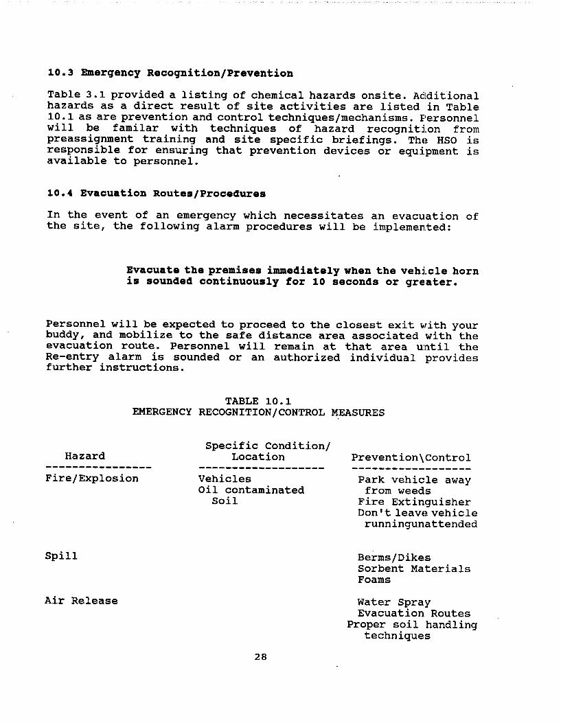
10.3 Emergency Recognition/Prevention
Table 3.1 provided a listing of chemical hazards onsite. Additional hazards as a direct result of site activities are listed in Table 10.1 as are prevention and control techniques/mechanisms. Personnel will be familar with techniques of hazard recognition from preassignment training and site specific briefings. ThE~ HSO is responsible for ensuring that prevention devices or equipment is available to personnel.
10.4 Evacuation Routes/Procedures
In the event of an emergency which necessitates an evacuation of the site, the following alarm procedures will be implemented:
Evacuate the premises immediately when the vehicle horn is sounded continuously for 10 seconds or gre:ater.
Personnel will be expected to proceed to the closest exit \lrith your buddy, and mobilize to the safe distance area associated with the evacuation route. Personnel will remain at that area until the Re-entry alarm is sounded or an authorized individual provides further instructions.
TABLE 10.1 EMERGENCY RECOGNITION/CONTROL ~EASURES
Hazard
Fire/Explosion
Spill
Air Release
Specific Condition/ Location
Vehicles Oil contaminated
Soil
28
Prevention\Control
Park vehicle away from weeds
Fire Extinguisher Don't leavE~ vehicle
runningunattended
Berms/Dikes Sorbent Materials Foams
Water Spray Evacuation Routes
Proper soil handling techniques

Figure 10.1 provides a map depicting evacuation routes for the site and immediate area. Also indicated are muster areas and safe distances in the event of a major incident.
10.7 Emergency Contact/Notification system
The following list provides names and telephone numbers for emergency contact personnel. In the event of a medical el~ergency, personnel will take direction from the HSO and no1:ify the appropriate emergency organization. In the event of a fire or spill, the site supervisor will notify the appropriate local, state, and federal agencies.
Organization Contact Telephone
Ambulance: 911
Police: 911
Fire: 911
State Police: District Office 841-·9256
Hospital 1: Lovelace Medical Center 262-·7222
Hospital 2: Presbyterian Hospital 841-·1111
Poison Control Center 843-·2551
Regional EPA: Richard Mayer 214-655-·6775
State Authority: Bruce swanton 1-827-·2923
National Response Center 800-424-·8802
Center for Disease Control 404-488-·4100
Chemtrec 800-424-·9555
29

FIGURE 10.1 EVACUATION ROUTES AND SAFE DISTANCES
fowvr
30
E V(( c vt:tle,. Llf'W"" i( IJ r·
f>U'fJ~&IfcvftJ,_. ~ -/J:1c WIA~
dtrecf.to, ~ e::( dls~A,t: t!.....
1 ~ i Ius I Zt?tJ ylll.s.

10.8 Emergency Medical Treatment Procedures
Any person who becomes ill or injured in the exclusion zom~ must be decontaminated to the maximum extent possible. If the injury or illness is minor, full decontamination should be completed and first aid administered prior to transport. If the patient's condition is serious, at least partial decontamination should be completed (i.e., complete disrobing of the victim and redrE~ssing in clean coveralls or wrapping in a blanket.) . First aid should be administered while awaiting an ambulance or paramedics. All injuries and illnesses must immediately be reported to the~ project manager.
Any person being transported to a clinic or hospital for t:reatment should take with them information on the chemical (s) they have been exposed to at the site. This information is included in Table 3.1.
Any vehicle used to transport contaminated personnel will be treated and cleaned as necessary.
10.9 Fire or Explosion
In the event of a fire or explosion, the local fire de!partment should be summoned immediately. Upon their arrival, the project manager or designated alternate will advise the fire comntander of the location, nature, and identification of the hazardous materials onsite.
If it is safe to do so, site personnel may:
o Use fire fighting equipment availa.ble onsite to control or extinguish the fire; and,
o Remove or isolate flammable or other hazardous materials which may contribute to the fire.
10.10 Spill or Leaks
In the event of a spill or a leak, site personnel will:
o Inform their supervisor immediately;
o Locate the source of the spillage and stop the flow if it can be done safely; and,
o Begin containment and recovery of the spilled materials
31

10.11 Emergency Equipment/Facilities
Figure 10.2 provides a map of the site and identifies the location of the following emergency equipment:
o Site Telephone
o First Aid Kit
32

FIGURE 10.2 SITE MAP WITH EMERGENCY EQUIPMENT LOCATED
(f) - r~~~,J.,,c..
~ - hr-sJ /It;/ ~'i tl
33

11.0 CONFINED SPACE ENTRY PROCEDURES
No confined space entry will be required during the inplen1entation of this work plan.
34

12.0 SPILL CONTAINMENT PROGRAM
The procedures defined in this section comprise the spill containment program in place for activities at the Site.
o All drums and containers used during the clean-·up shall meet the appropriate DOT, OSHA, and EPA regulators for the waste that they will contain.
o Drums and containers shall be inspected and their integrity containers because of accessable handling.
assured prior to being moved. Drums or that cannot be inspected before being moved storage conditions, shall be positioned in an
location and inspected prior to further
o Operations on site will be organized so as to minimize the amount of drum or container movement.
o Employees involved in the drum or container operations shall be warned of the hazards associated ''lith the containers.
o Where spills, leaks, or ruptures may occur, adequate quanti ties of spill containment equipment ( al:1sorbent, pillows, etc.) will be stationed in the immediate area. The spill containment program must be suffic:::ient to contain and isolate the entire volume of hazardous substances being transferred.
o Drums or containers that cannot be moved without failure, shall be emptied into a sound container.
o Fire extinguishing equipment meeting 29 CFR part 1910. subpart 1 shall be on hand and ready for use to1 control fires.
35

NOTE: The following Level of Protection modifications were made by the plan preparer:
Level B changed to Level C - Modified for Grid layout
Reasons: Risk of inhalation is very small during grid layout.
Level B changed to Level C - Modified for Surface soil sampling
Reasons: Risk of inhalation is very small for surface soil sampling.
Level B changed to Level C - Modified for Soil excavations
Reasons: Risk of inhalation is moderate for equipment operator, dust generation will be minimized by use of sprayed water.
36