Embed Size (px)
Citation preview

Public Informational Meeting on the
Former Sparrows Point Steel Mill
Environmental Cleanup
September 30, 2015

Regulatory Framework for Environmental Work Moving Forward
Environmental Work On the Entire Site For MDE and EPA
MDE will assume primary responsibility for overseeing implementation of the
onshore work in consultation and cooperation with EPA
EPA will assume primary responsibility for implementation of the offshore
work in consultation and cooperation with MDE
Settlement Agreement
(SA)
EPA, DOJ and SPT
Administrative
Consent Order
(ACO)
MDE and SPT
Amended 1997
Consent Decree
(CD)
MDE, EPA, DOJ
and SPL

Sampling Data for Risk Assessment
Inhalation
Dermal contact
Inhalation
Ingestion of soil
Dermal contact
Inhalation of volatiles
Ingestion of water
Dermal contact
Fish Consumption
Ingestion
Leaching
Runoff
Vapor Intrusion
Water Table
Groundwater
discharge
Groundwater Transport
Air Transport
Sediments Soils
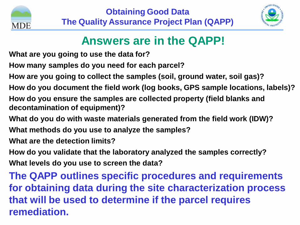
Answers are in the QAPP! What are you going to use the data for?
How many samples do you need for each parcel?
How are you going to collect the samples (soil, ground water, soil gas)?
How do you document the field work (log books, GPS sample locations, labels)?
How do you ensure the samples are collected property (field blanks and
decontamination of equipment)?
What do you do with waste materials generated from the field work (IDW)?
What methods do you use to analyze the samples?
What are the detection limits?
How do you validate that the laboratory analyzed the samples correctly?
What levels do you use to screen the data?
The QAPP outlines specific procedures and requirements
for obtaining data during the site characterization process
that will be used to determine if the parcel requires
remediation.
Obtaining Good Data
The Quality Assurance Project Plan (QAPP)

The Quality Assurance
Project Plan (QAPP) In Action!
Sampling Location Identification
Collecting Field Blanks
Equipment Decontamination Trailer
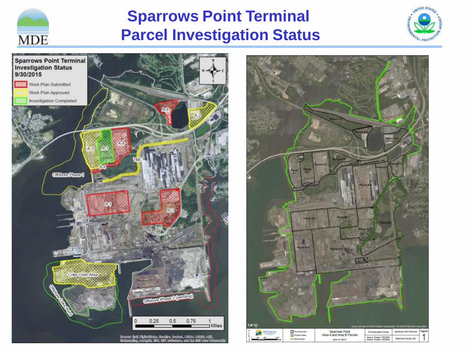
Sparrows Point Terminal
Parcel Investigation Status

Area A2
Approximately 41 Acres-Currently Occupied by
Reservoir Warehouse and DACS Building also
called the In Process Storage Building.
Final Phase II Work Plan received September 4, 2015
Field Work began September 15,
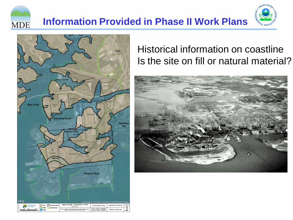
Information Provided in Phase II Work Plans
Historical information on coastline
Is the site on fill or natural material?

Determining Sample Locations
Area A2 Example
1952 Aerial Photo 1966 Aerial Photo 1971 Aerial Photo
Historical Plant Drawings with potential
sources of contamination (sumps, pits,
tanks, etc.) identified
2014 Phase I including other Historical
Investigations and Aerial Photos
QAPP-Worksheet 17 Minimum Sampling
Density Requirements
Site Visits to observe current conditions

Area A2 Final Work Plan

Area A2 Sampling Table

Area A4 New Cold Mill Complex
Built in the late 1990’s approximately 800,000 square foot NCMC produced light, flat-rolled
sheet steel from hot-rolled steel; which was supplied from Sparrows Point's hot strip mill. The
cold-rolled products from Sparrows Point were used in containers, tubing, machinery, storage
tanks, automotive parts, metal furniture, electrical lighting equipment and hardware. The NCMC,
which replaced the old cold mill, housed an in-line continuous pickler, which cleaned steel prior
to rolling. The pickler was linked to a sheet steel cold reduction section that consisted of a five-
stand tandem mill. Additionally, the NCMC contained a hydrogen batch annealing facility, a
combination skin pass mill and tension leveling line, a coil build-up and inspection line, a
packaging line, cranes, storage areas and offices.

Area A4 New Cold Mill Complex
Potential Recognized Environmental Concerns

Area A4 New Cold Mill Complex
April 2015 Occupancy Assessment to evaluation sub-slab
soil gas conditions. 19 Sub-slab Soil Gas Sampling
Locations. No elevated levels of soil vapor contaminants
were detected above MDE Tier 1 Screening Levels
August 2015 Phase II Investigation Work Plan Under Review
Proposed 19 soil borings and 22 ground water samples
including three existing wells

Area A8 Former Air Products
27 acres Structures have been Demolished
Reviewing July 2015 Work Plan
Proposed 17 Soil borings and 13
Ground water samples

Area B3
Parcel B3 (95 acres) was formerly
occupied by the following buildings or
facilities: Fire and Police Station, Roll
Grinding Facility, Human Resources
Building, (Mason’s) Garage Building,
Residential Town Area and various
office/administrative buildings. Several
office and other buildings still exist and
are currently in use.
Currently Reviewing Phase II Work Plan
dated July 2015
Proposed 27 soil borings

Area B8 Billet Building Approximately 13. 5 Acres
Historically referred to as the Billet
Conditioning Building, Billet Prep
Building and the Billet Record Building
Building to remain for reuse
Phase II Work Plan dated September
18, 2015 under review

Area B8 Billet Building Determining Sample Locations Includes a Site Visit to Observe Conditions
Based on visual
observations and
the age of building
a lead paint survey
was completed
and the report
submitted in
August 2015

Includes the following proposed samples:
44 borings-building exterior and interior
12 new groundwater samples
2 existing wells sampled
8 soil gas samples within the building
Area B8 Billet Building Phase II Work Plan

Area A1 Environmental Assessment Work Completed
November 2014
26 Soil Borings 5 Groundwater Samples
February 2015
20 Additional Soil Borings
Sampling Identified Metals (Arsenic and
Vanadium), PAHs (benzo(a)pyrene), Aroclor
1260 and Total Petroleum Hydrocarbons-
Diesel Range Organics (TPH-DRO) in Soil
Dissolved metals and TPH-DRO/GRO in
shallow ground water

Area A1 Response Action Plan
April 23, 2015 RAP Submitted
May 11, 2015 Public Informational Meeting
July 6, 2015 Revised RAP Submitted
July 14, 2015 Revised RAP Approved
August 21, 2015 RAP Addendum 1 Submitted
August 24, 2015 RAP Addendum 1 Approved
The entire 48.5 acre site will be capped
with either concrete, asphalt paving or
clean approved fill material over a
geotextile fabric in landscaped areas.
Institutional controls will include a
groundwater use deed restriction,
industrial land use restriction and cap
maintenance requirements.

Area B Site Wide Ground Water
Work Plan Dated September
18, 2015
Objectives:
Determine the presence or
absence of impacts to
groundwater in the central
portion of Area B
Identify potential continuing
sources of groundwater
contamination, and
Characterize the quality of
groundwater at the perimeter
of the Site that potentially is
discharging to surface water

Area B Site Wide Ground Water
Determining Well Locations

Tin Mill Canal
Tin Mill Canal Facts:
Approximately 7,500 feet in length.
30-50 feet wide and 15 feet below grade.
Constructed in 1960’s from slag.
Conveyance for stormwater runoff and groundwater
baseflow from 800 acres of Sparrows Point site.
Historically received wastewater discharges from
numerous manufacturing facilities associated with
steelmaking and steel finishing operations.
Average flow during dry weather 3,000 to 4,000
gallons per minute (gpm) but can increase to
50,000 gpm during storm events.
Water collected from Tin Mill Canal routed to
Humphrey’s Creek Waste Water Treatment Plant for
treatment prior to discharge under NPDES permit to
outfall 14.

Tin Mill Canal Sediment Cleanout Sampling and Analysis Work Plan
Work plan to determine volume of sediments to
be removed and disposal options
Collect samples of settled material for physical
and chemical properties at 17 transect locations
Cleanout goal to remove settled material,
provide erosion and sediment control,
stabilization of canal floor and sidewalls and
subsequently improve quality of water
discharge from site.

Tin Mill Canal Work Plan Sediment Sampling Locations
Shallow and Deep
Sediment Samples
Collected 2015
Report Anticipated
November 2015

Area A3 Rod and Wire Mill
The former mill produced rod and wire products
from 1940's to early 1980's
Approximately 60 acres of the former mill have
been demolished.
Manufacturing process included leaching of zinc
ore and treatment to remove cadmium impurities.
Storage of leach residue, dewatered sludge and
excess filtrate resulted
in soil and ground water
contamination with zinc
and cadmium.
Interim measures
pump and treat system
In operation since 1987
Aerial View 1982

A3 Rod and Wire Mill Work Plan
Final Work Plan Received September 21, 2015
Field Work Underway
Characterization Sampling Plan:
61 Test borings-sample surface and subsurface soils for
VOCs, SVOCs, Metals, Cobalt, Cyanide, Oil and Grease,
Hexavalent Chromium and PCBs (surface soil).
10 new locations and 10 existing shallow and intermediate
ground water wells sampled for VOCs, SVOCs, Metals,
Cobalt, Cyanide, Oil and Grease, and Hexavalent Chromium
Treatment Options Evaluation:
Additional testing-SPLP, TCLP, total and free organic carbon,
ph, phosphate, grain size to support modeling and treatment
options
Ground water modeling and Aquifer Testing to confirm model
Permeable Reactive Barrier Wall Alignment Testing-4 borings
to 50 feet below grade
Bench testing for treatment options with ground water and
soil stabilization alternatives

Coke Oven Area Historic Operations

Coke Oven Area Interim Measures

Coke Oven Pre-Design Investigation Work Plan Goals
Conduct feasibility studies of alternatives including enhanced vacuum recovery, passive
containment walls, and bioremediation for incorporation into final remedy
Delineate lateral extent of free phase product in Cell 2 and Cell 6 areas and evaluate potential
communication.
Delineate lateral and vertical extent of DNAPL in Cell 5 Area.
Evaluate effectiveness of Cell 1 and Cell 3 treatment systems.
Define Area-Wide groundwater elevations, flow directions and gradients.
Define Area-Wide dissolved phase constituent concentrations in the shallow and intermediate
groundwater zones.
Cell 2

Coke Oven Pre-Design Investigation
Work Completed
52 delineation borings ranging in depth from 16 to 87 feet below ground surface were completed.
Four of the borings in the Cell 2 area were deep borings.
Installation of 3 new monitoring/recovery wells completed in
the Cell 6 area.
Installation of 3 new monitoring/recovery wells in the
Cell 5 area.
Collection of 15 groundwater samples from three discrete
depths (15, 25, and 45 feet below ground surface) at Cell 3.
Cell 6
Cell 6
Cell 5

Coke Oven Pre-Design Investigation
Work Completed

• Completed further delineation of light (LNAPL) and dense
(DNAPL) hydrocarbon product in Cells 2,4 and 6
• Measured depth to clay layer in Cell 2 area for barrier wall
feasibility evaluation
• Completed high vacuum product recovery tests in Cells 2 and
6
• Completed DNAPL recoverability test in Cell 4
• Completed testing to rebalance air sparge/Vapor extraction in
Cell 3
Coke Oven Pre-Design Investigation Work Plan
Work Completed
Cell 3
LNAPL
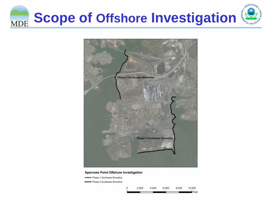
Scope of Offshore Investigation

Phase 1 Off-Shore Sampling
First round sampling included collection of surface
sediment from 20 locations, along eight transects
and sediment core samples from 12 locations
Surface sediments (6 inch) show elevated metals.
Sediment core samples (5-6 feet) near Tin Mill Canal
show high concentrations of oil and grease, sheen
and petroleum odor
Second round sampling work plan approved by
Agencies on January 14, 2015
Second round sampling plan includes pore water
samples and additional surface sediment samples at
co-locations.
Second Round of Sampling has been completed.
Risk Assessment and Final Report currently being
prepared for submittal to Agencies

Phase 2 Off-Shore Sampling
A contractor has been selected and
preliminary planning underway
Includes a review of existing information
regarding current and historic site activities
and stormwater discharge locations
Will require review of results from ground
water wells to be installed along shoreline
prior to determining off-shore sampling scope

Coke Point Land Fill Proposed Monitoring Wells
Additional Wells Approved February 12, 2015
Wells installed Spring 2015

Coke Point Land Fill Monitoring Well Installation
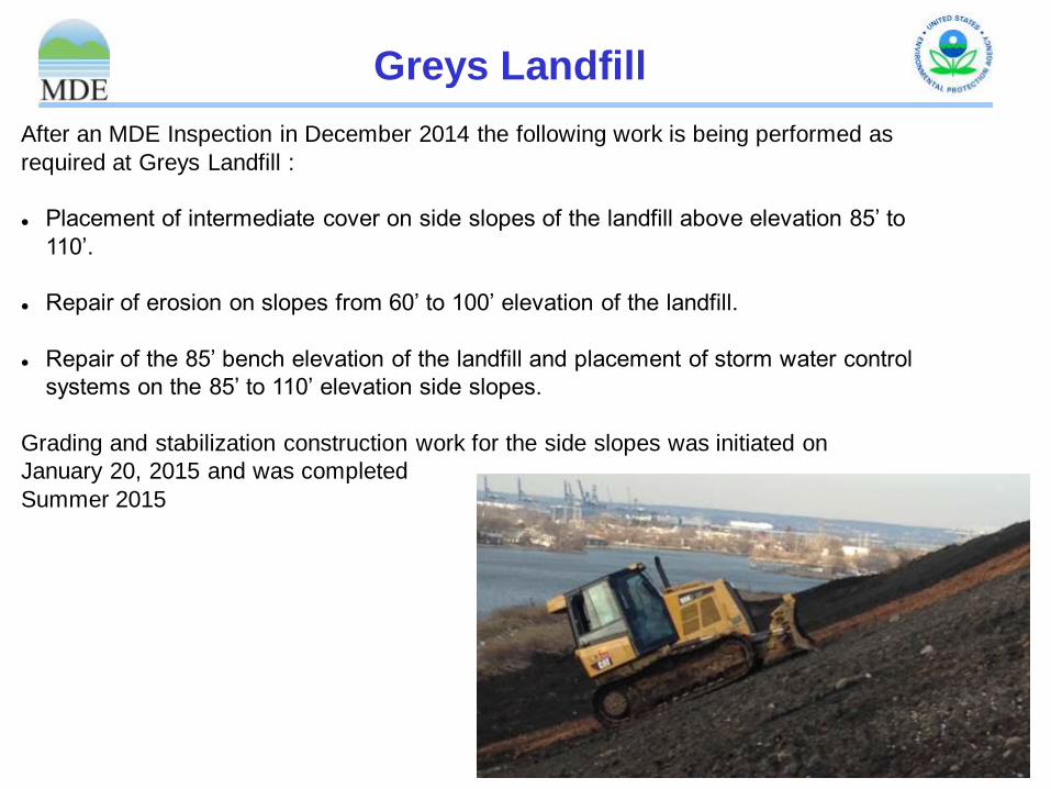
Greys Landfill
After an MDE Inspection in December 2014 the following work is being performed as
required at Greys Landfill :
Placement of intermediate cover on side slopes of the landfill above elevation 85’ to
110’.
Repair of erosion on slopes from 60’ to 100’ elevation of the landfill.
Repair of the 85’ bench elevation of the landfill and placement of storm water control
systems on the 85’ to 110’ elevation side slopes.
Grading and stabilization construction work for the side slopes was initiated on
January 20, 2015 and was completed
Summer 2015

Demolition Progress

Materials Management
Plan submitted and
approved for reuse of
concrete and brick. The
plan requires sampling of
each pile after crushing
prior to reuse as backfill.
Plans submitted for cleanout and
engineered backfill for each pit.
Some pits are up to 60 feet below
grade.
Site Restoration Process

Recycling
Recycled Materials:
Steel, Copper, Aggregate: 1,275,500 tons
Oils: 245,000 gallons
Batteries: 157,000 lbs
Light Tubes & Ballasts: 78,300 lbs
Electronic Waste: 273,000 lbs
Paper: 23,000 lbs

For Additional Information From EPA:
Andrew Fan
U.S. Environmental Protection Agency Region 3 Mail Stop: 3LC20 1650 Arch Street
Philadelphia, PA 19103-2029 (215) 814-3426

For Additional Information From MDE
Barbara Brown
Land Management Administration
Maryland Department of the Environment
1800 Washington Boulevard
Baltimore, Maryland 21230
(410) 537-3493
Visit the MDE Website! http://www.mde.maryland.gov

Questions?
Dredging near the Ore Pier