Embed Size (px)
Citation preview
All rights reserved. No part of this document may be stored, copied or transmitted, by any means, without the permission in written of the Legal Owner
© 2016 ALBEDO Telecom
Joan d’Austria, 112 - Barcelona - SP - 08018
www.albedotelecom.comChalfont St Peter - Bucks - UK - SL9 9TR
W H I T E PA P E R
Synchronization & Mobile networks1. INTRODUCTION
For many years the frequency synchronization requirements of GSM, 3G andUMTS networks were satisfied by means of TDM signals such as T1 or E1. Thissolution was straight forward because the infrastructure to support mobilebackhaul was made of SONET / SDH, thereby the synchronization signal couldbe extracted from the PHY layer or being transported through a separate net-work. In any case both transport and synchronization were based on TDM tech-nologies.
From Circuit to Packet migration
However, during the last decade many things have changed, mainly becausemobile operators have been abandoning SONET/SDH circuits while adoptingEthernet / MPLS / IP to support new mobile backhaul architectures. This is a ma-jor challenge for base stations that always require a very accurate synchroniza-tion that native Ethernet can’t supply.
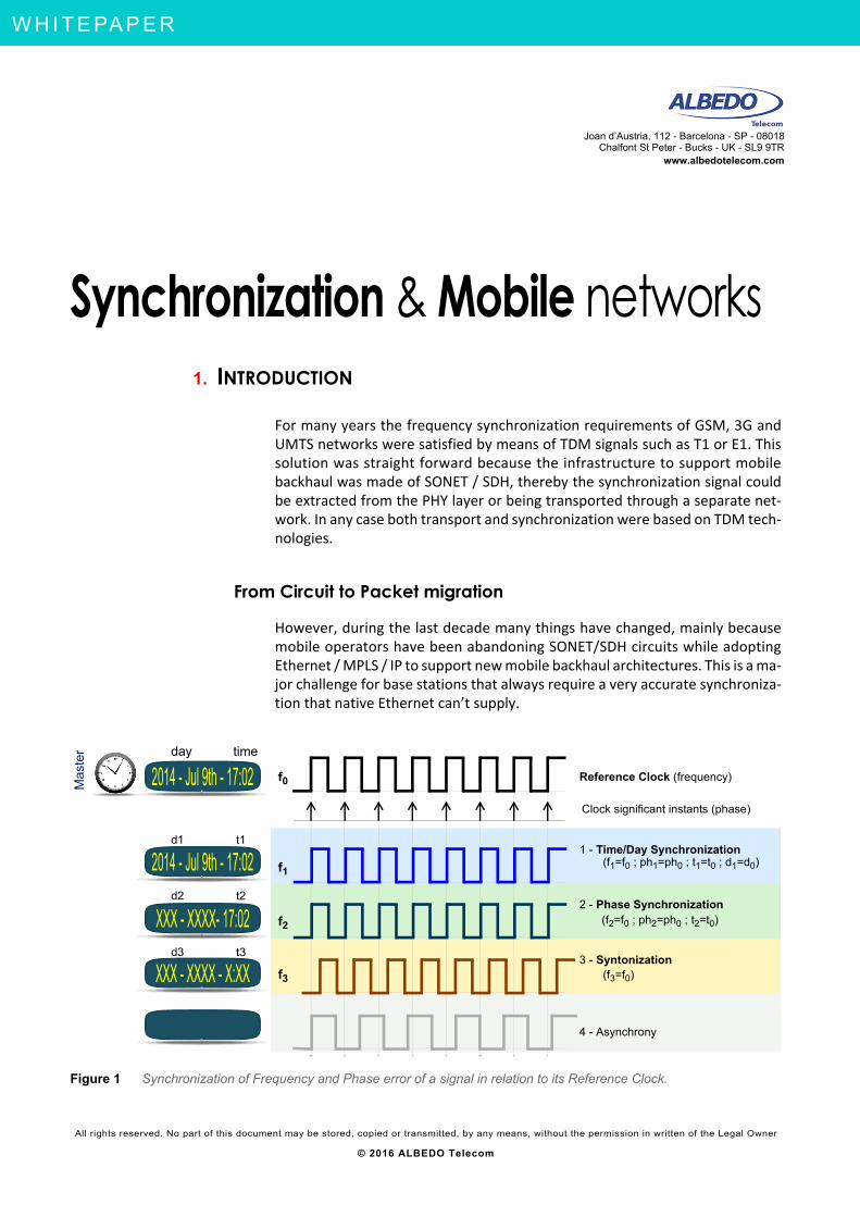
Figure 1 Synchronization of Frequency and Phase error of a signal in relation to its Reference Clock.
Reference Clock (frequency)
Clock significant instants (phase)
2014 - Jul 9th - 17:02
1 - Time/Day Synchronization
2 - Phase Synchronization
3 - Syntonization
4 - Asynchrony
(f1=f0 ; ph1=ph0 ; t1=t0 ; d1=d0)
(f2=f0 ; ph2=ph0 ; t2=t0)
(f3=f0)
f0
f2
f3
day time
d2 t2
d3 t3
2014 - Jul 9th - 17:02
XXX - XXXX- 17:02
XXX - XXXX - X:XX
Mas
ter
f1
d1 t1
Network ing & Telecoms - S y n c h r o n i z a t i o n & M o b i l e n e t w o r k s
2 / 15
A L
B E
D O
- W
H I
T E
P A
P E
R
AL B
ED
O T
ele
com
- R
eg
iste
r ed
in B
arc
elo
na
, B
oo
k 41
61
3, P
age
15
5,
Sh
ee
t B-3
9 08
86
- V
AT
: E
SB
652
30
22
Pr o f es s i ona l Te l eco m S o l u t io ns
TEST- LABOS - TAPS - WAN EMULATION - E1 - GBE - SYNCE - WLESS - LTE - 3G - IPTV - VoIP - QoS - SLA - ONEWAY - DATACOM - POLQA - PTP - JITTER - WANDER
Why Synchronization is required?
Synchronization enables many services including assisted navigation, loca-tion, and emergency calls. Moreover, synchronization is fundamental to ev-ery cellular technology otherwise they would not even work. Base stationsmust calculate permanently the distance to every single mobile operating intheir cell and the neighboring cells. Base station and mobiles have to gener-ate exactly the up/down frequencies and have to access to transmissiontime-slots. There are many reasons to keep a good synchronization:
• to calculate the distance to mobile terminals,
• to support geographical localization services,
• to control the transmission power,
• to avoid interferences with other cells and base stations,
• to manage handovers,
• to get accurate access to the time-slots,
• to compensate the propagation delay,
• to reuse frequencies efficiently,
• to plan small and micro cells,
• to calculate the billing.
Then we agree that synchronization is fundamental for any basic mobile ser-vice therefore it is just impossible to get rid of it.
Some background in multiplexing & synchronization
Multiplexing and Multiple Access
Multiplexing is defined as the process by which several signals from differentchannels share a channel with greater capacity. Basically, a number of chan-nels share a common transmission medium with the aim of reducing costs
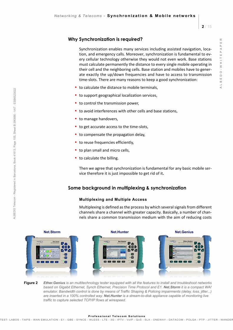
Figure 2 Ether.Genius is an multitechnology tester equipped with all the features to install and troubleshoot networks based on Gigabit Ethernet, Synch Ethernet, Precision Time Protocol and E1. Net.Storm it is a compact WANemulator. Bandwidth control is done by means of Traffic Shaping & Policing impairments (delay, loss, jitter...),are inserted in a 100% controlled way. Net.Hunter is a stream-to-disk appliance capable of monitoring live traffic to capture selected TCP/IP flows at wirespeed.
Net.Storm Net.Hunter Net.Genius

Network ing & Telecoms - S y n c h r o n i z a t i o n & M o b i l e n e t w o r k s
3 / 15
A L
B E
D O
- W
H I
T E
P A
P E
R
AL B
ED
O T
ele
com
- R
eg
iste
r ed
in B
arc
elo
na
, B
oo
k 41
61
3, P
age
15
5,
Sh
ee
t B-3
9 08
86
- V
AT
: E
SB
652
30
22
Pr o f es s i ona l Te l eco m S o l u t io ns
TEST- LABOS - TAPS - WAN EMULATION - E1 - GBE - SYNCE - WLESS - LTE - 3G - IPTV - VoIP - QoS - SLA - ONEWAY - DATACOM - POLQA - PTP - JITTER - WANDER
and complexity in the network. When the sharing is carried out with respectto a remote resource, such as a satellite, this is referred to as multiple accessrather than multiplexing (see Figure 3). Some multiplexing technologies are:
• Frequency multiple access (FDMA): Assigns a portion of the total band-width to each of the channels.
• Time division multiple access (TDMA): Assigns all the transport capacity se-quentially to each of the channels.
• Code-division multiplexing access (CDMA) air interface facilitates multipleaccess over a channel using spread-spectrum with a code per transmitter
• Polarization division multiple access (PDMA): polarization direction can beused as a multiple access technique in installations that use microwaves.
• Space division multiple access (SDMA): using directional antennas the samefrequency can be reused, provided the antennas are correctly adjusted.
Duplexing
Base stations use today three two technologies to multiplex upstream anddownstream channels: frequency division duplexing (FDD), time division du-plexing (TDD) and code division multiplexing (CDM).
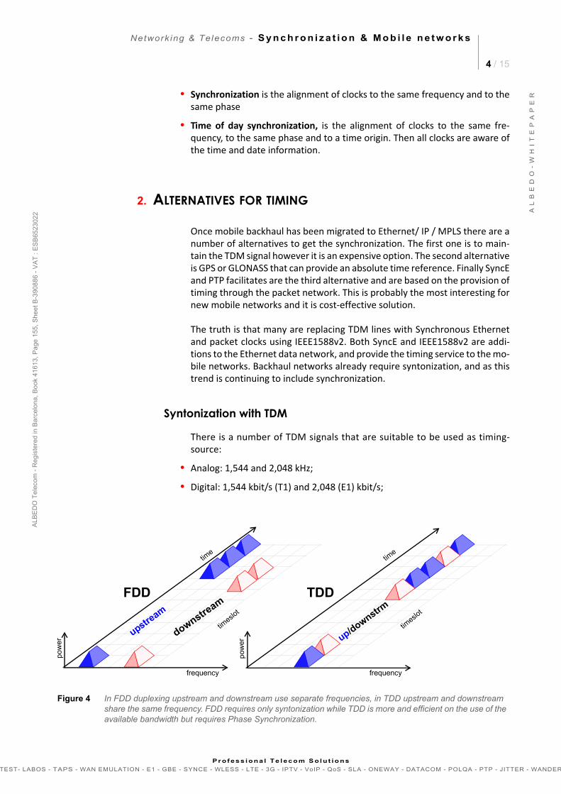
• FDD base stations air interface uses separate frequencies for the up/down-link, then requires only a frequency synchronization.
• TDD base stations air interface uses the same frequency for the up/down-link then an absolute time and phase reference is required to get access totime slots (see Figure 4).
• Syntonization and Synchronization
• Are similar concepts but not exactly the same:
• Syntonization is the alignment of clocks to the same frequency, asSDH/SONET used to do
DTE-AB1
DTE-BB2
DTE-n
Bn
.
.
.
Figure 3 Multiplexing consolidates lower capacity channels into a higher channel. Frequency division multiplexing (FMDA). Time division multiplexing (TDMA) and Code division multiplexing (CDMA).
AAB
CDE
FBCDEFAB
TDMAFDMA
time
0 0 1 0 1 1 1 0 1 1 1 0 1 1 1 0 0 1
1 1 0 1 0 0 0 1 0 1 1 0 1 1 1 0 0 1
code
bit
CDMA
frequency
DTE-AB1
DTE-BB2
DTE-n
Bn
.
.
. Transmission media
ΣBi
n
m
n
m
Multiplexer DemultiplexerMultiplexing
Bi = bandwidth
.
.
.
.
.
.
pattern
data
signal
0 1
bit
Network ing & Telecoms - S y n c h r o n i z a t i o n & M o b i l e n e t w o r k s
4 / 15
A L
B E
D O
- W
H I
T E
P A
P E
R
AL B
ED
O T
ele
com
- R
eg
iste
r ed
in B
arc
elo
na
, B
oo
k 41
61
3, P
age
15
5,
Sh
ee
t B-3
9 08
86
- V
AT
: E
SB
652
30
22
Pr o f es s i ona l Te l eco m S o l u t io ns
TEST- LABOS - TAPS - WAN EMULATION - E1 - GBE - SYNCE - WLESS - LTE - 3G - IPTV - VoIP - QoS - SLA - ONEWAY - DATACOM - POLQA - PTP - JITTER - WANDER
• Synchronization is the alignment of clocks to the same frequency and to thesame phase
• Time of day synchronization, is the alignment of clocks to the same fre-quency, to the same phase and to a time origin. Then all clocks are aware ofthe time and date information.
2. ALTERNATIVES FOR TIMING
Once mobile backhaul has been migrated to Ethernet/ IP / MPLS there are anumber of alternatives to get the synchronization. The first one is to main-tain the TDM signal however it is an expensive option. The second alternativeis GPS or GLONASS that can provide an absolute time reference. Finally SyncEand PTP facilitates are the third alternative and are based on the provision oftiming through the packet network. This is probably the most interesting fornew mobile networks and it is cost-effective solution.
The truth is that many are replacing TDM lines with Synchronous Ethernetand packet clocks using IEEE1588v2. Both SyncE and IEEE1588v2 are addi-tions to the Ethernet data network, and provide the timing service to the mo-bile networks. Backhaul networks already require syntonization, and as thistrend is continuing to include synchronization.
Syntonization with TDM
There is a number of TDM signals that are suitable to be used as timing-source:
• Analog: 1,544 and 2,048 kHz;
• Digital: 1,544 kbit/s (T1) and 2,048 (E1) kbit/s;
Figure 4 In FDD duplexing upstream and downstream use separate frequencies, in TDD upstream and downstream share the same frequency. FDD requires only syntonization while TDD is more and efficient on the use of the available bandwidth but requires Phase Synchronization.
FDD
time
timeslo
t
frequency
upstream
downstream
TDD
time
timeslo
t
frequency
up/downstrm
pow
er
pow
er
Network ing & Telecoms - S y n c h r o n i z a t i o n & M o b i l e n e t w o r k s
5 / 15
A L
B E
D O
- W
H I
T E
P A
P E
R
AL B
ED
O T
ele
com
- R
eg
iste
r ed
in B
arc
elo
na
, B
oo
k 41
61
3, P
age
15
5,
Sh
ee
t B-3
9 08
86
- V
AT
: E
SB
652
30
22
Pr o f es s i ona l Te l eco m S o l u t io ns
TEST- LABOS - TAPS - WAN EMULATION - E1 - GBE - SYNCE - WLESS - LTE - 3G - IPTV - VoIP - QoS - SLA - ONEWAY - DATACOM - POLQA - PTP - JITTER - WANDER
• STM-n/OC-m line codes: from which one of the above-mentioned signalscan be derived, by means of a specialized circuit.
The employment of STM-n/OC-m signals has the advantage of using the S1byte to enable synchronization status messages (SSMs) to indicate the per-formance of the clock with which the signal was generated. These messagesare essential in reconstructing the synchronization network automatically incase of failure. They enable the clocks to choose the best possible reference,and, if none is available that offers the performance required, they enter theholdover state.
GPS or GLONASS synchronization
GPS has been available for many years (today also the russian GLONASS) andoften we have heard ‘Why do not incorporate GPS at each base station?’ un-fortunately it is vulnerable solution to jamming and interferences. Moreover,GPS cells are everyday smaller and access to aerials is not always possible be-cause are deployed indoors, in stadiums or shopping centers where access tosatellite signals could no be practical or it is very expensive. Even CDMA op-erators who traditionally have relied on GPS, do not it consider any more asan acceptable solution due to operational and political reasons.
G.8260Definitions
G.8261.1PDV limits
G.8262SyncE Slave Clock
G.8261SyncE- Jitter/Wander
G.8263Packet Based Clocks
G.8264Time Distribution
G.8265.1PTP frequency profile
Frequency Phase
Requirements
Clock
Methods
Profiles
G.826.x G.827.x
G.8265Frequency Delivery
G.8271Time & Phase
G.8272Primary Ref. Clock
G.8273Master&Bound clocks
G.8275Phase Delivery
G.8275.1PTP phase profile
G.8271.1Time & Phase needs
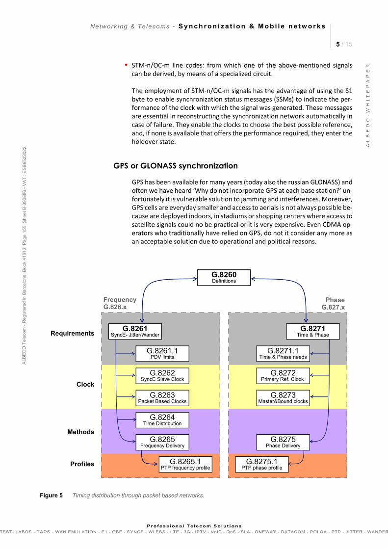
Figure 5 Timing distribution through packet based networks.
Network ing & Telecoms - S y n c h r o n i z a t i o n & M o b i l e n e t w o r k s
6 / 15
A L
B E
D O
- W
H I
T E
P A
P E
R
AL B
ED
O T
ele
com
- R
eg
iste
r ed
in B
arc
elo
na
, B
oo
k 41
61
3, P
age
15
5,
Sh
ee
t B-3
9 08
86
- V
AT
: E
SB
652
30
22
Pr o f es s i ona l Te l eco m S o l u t io ns
TEST- LABOS - TAPS - WAN EMULATION - E1 - GBE - SYNCE - WLESS - LTE - 3G - IPTV - VoIP - QoS - SLA - ONEWAY - DATACOM - POLQA - PTP - JITTER - WANDER
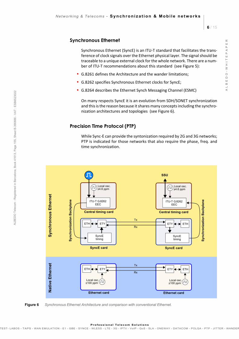
Synchronous Ethernet
Synchronous Ethernet (SyncE) is an ITU-T standard that facilitates the trans-ference of clock signals over the Ethernet physical layer. The signal should betraceable to a unique external clock for the whole network. There are a num-ber of ITU-T recommendations about this standard (see Figure 5):
• G.8261 defines the Architecture and the wander limitations;
• G.8262 specifies Synchronous Ethernet clocks for SyncE;
• G.8264 describes the Ethernet Synch Messaging Channel (ESMC)
On many respects SyncE it is an evolution from SDH/SONET synchronizationand this is the reason because it shares many concepts including the synchro-nization architectures and topologies (see Figure 6).
Precision Time Protocol (PTP)
While Sync-E can provide the syntonization required by 2G and 3G networks;PTP is indicated for those networks that also require the phase, freq. andtime synchronization.
Figure 6 Synchronous Ethernet Architecture and comparison with conventional Ethernet.
Local osc.
Syn
chro
niz
atio
n B
ackp
lan
e ITU-T G.8262EEC
±4.6 ppm
SyncEtiming
SyncE card
Central timing card
ETH ETY
Ethernet card
ETH ETY
Local osc.±100 ppm
Local osc.
Syn
chro
niz
atio
n B
ackp
lan
eITU-T G.8262EEC
SSU
±4.6 ppm
SyncEtiming
SyncE card
Central timing card
ETY ETH
Ethernet card
ETY ETH
Local osc.±100 ppm
Tx
Rx
Tx
Rx
Syn
ch
ron
ou
s E
ther
ne
tN
ati
ve E
the
rnet
Network ing & Telecoms - S y n c h r o n i z a t i o n & M o b i l e n e t w o r k s
7 / 15
A L
B E
D O
- W
H I
T E
P A
P E
R
AL B
ED
O T
ele
com
- R
eg
iste
r ed
in B
arc
elo
na
, B
oo
k 41
61
3, P
age
15
5,
Sh
ee
t B-3
9 08
86
- V
AT
: E
SB
652
30
22
Pr o f es s i ona l Te l eco m S o l u t io ns
TEST- LABOS - TAPS - WAN EMULATION - E1 - GBE - SYNCE - WLESS - LTE - 3G - IPTV - VoIP - QoS - SLA - ONEWAY - DATACOM - POLQA - PTP - JITTER - WANDER
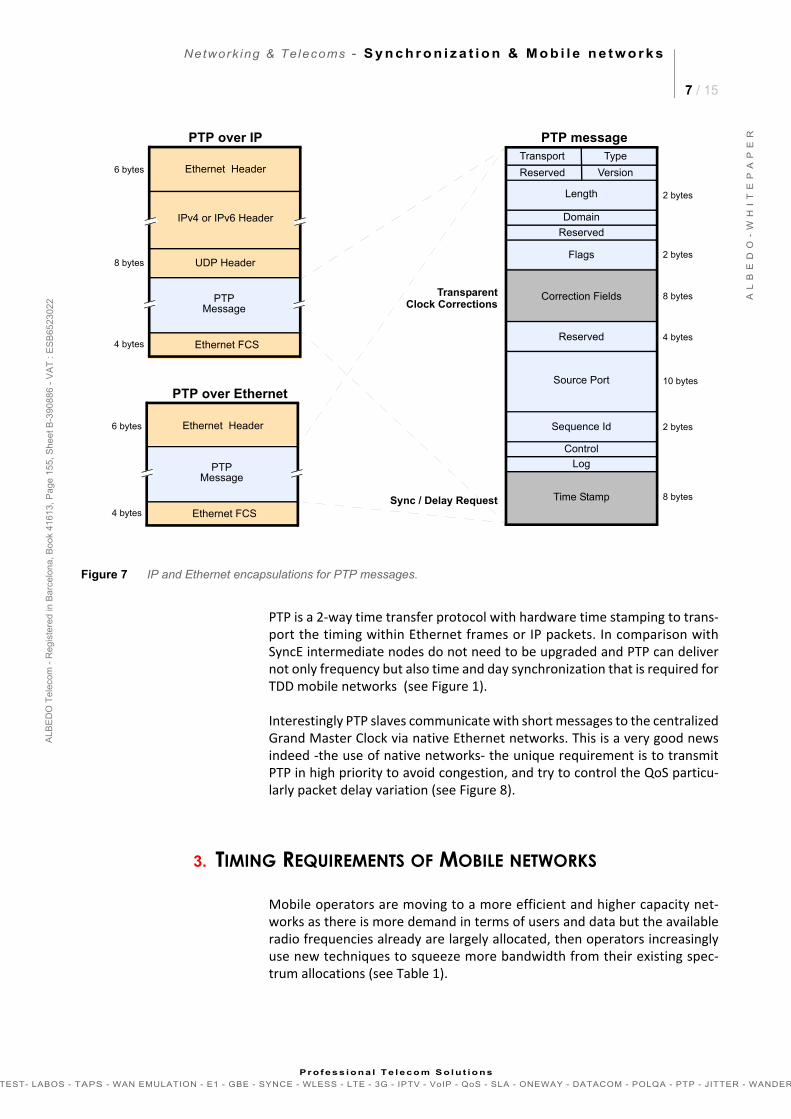
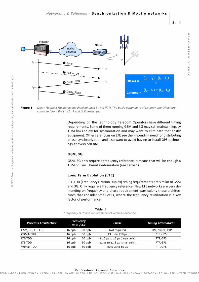
PTP is a 2-way time transfer protocol with hardware time stamping to trans-port the timing within Ethernet frames or IP packets. In comparison withSyncE intermediate nodes do not need to be upgraded and PTP can delivernot only frequency but also time and day synchronization that is required forTDD mobile networks (see Figure 1).
Interestingly PTP slaves communicate with short messages to the centralizedGrand Master Clock via native Ethernet networks. This is a very good newsindeed -the use of native networks- the unique requirement is to transmitPTP in high priority to avoid congestion, and try to control the QoS particu-larly packet delay variation (see Figure 8).
3. TIMING REQUIREMENTS OF MOBILE NETWORKS
Mobile operators are moving to a more efficient and higher capacity net-works as there is more demand in terms of users and data but the availableradio frequencies already are largely allocated, then operators increasinglyuse new techniques to squeeze more bandwidth from their existing spec-trum allocations (see Table 1).
Figure 7 IP and Ethernet encapsulations for PTP messages.
Transport
2 bytes
Type
Length
Domain
Reserved
Reserved
Flags
Correction Fields
Reserved
Version
Source Port
Sequence Id
Control
Log
Time Stamp
2 bytes
8 bytes
4 bytes
10 bytes
2 bytes
8 bytesSync / Delay Request
TransparentClock Corrections
Ethernet FCS
Ethernet Header6 bytes
4 bytes
UDP Header8 bytes
IPv4 or IPv6 Header
PTP
PTP over IP
Message
Ethernet FCS
Ethernet Header6 bytes
4 bytes
PTP
PTP over Ethernet
Message
PTP message
Network ing & Telecoms - S y n c h r o n i z a t i o n & M o b i l e n e t w o r k s
8 / 15
A L
B E
D O
- W
H I
T E
P A
P E
R
AL B
ED
O T
ele
com
- R
eg
iste
r ed
in B
arc
elo
na
, B
oo
k 41
61
3, P
age
15
5,
Sh
ee
t B-3
9 08
86
- V
AT
: E
SB
652
30
22
Pr o f es s i ona l Te l eco m S o l u t io ns
TEST- LABOS - TAPS - WAN EMULATION - E1 - GBE - SYNCE - WLESS - LTE - 3G - IPTV - VoIP - QoS - SLA - ONEWAY - DATACOM - POLQA - PTP - JITTER - WANDER
Depending on the technology Telecom Operators have different timingrequirements. Some of them running GSM and 3G may still maintain legacyTDM links solely for syntonization and may want to eliminate that costlyequipment. Others are focus on LTE see the impending need for distributingphase-synchronization and also want to avoid having to install GPS technol-ogy at every cell site.
GSM, 3G
GSM, 3G only require a frequency reference, it means that will be enough aTDM or SyncE based syntonization (see Table 1).
Long Term Evolution (LTE)
LTE-FDD (Frequency Division Duplex) timing requirements are similar to GSMand 3G. Only require a frequency reference. New LTE networks are very de-manding on frequency and phase requirement, particularly those architec-tures that consider small cells, where the frequency reutilization is a keyfactor of performance..
Table 1Frequency & Phase requirements of wireless networks.
Wireless Architecture FrequencyBase / Air Phase Timing Alternatives
GSM, 3G, LTE-FDD 16 ppb 50 ppb Not required TDM, SyncE, PTPCDMA-TDD 16 ppb 50 ppb ±3 µs to ±10 µs PTP, GPSLTE-TDD 16 ppb 50 ppb ±1.5 µs to ±5 µs (large cells) PTP, GPSLTE-TDD 16 ppb 50 ppb ±1 µs to ±1.5 µs (small cells) PTP, GPSWimax-TDD 16 ppb 50 ppb ±0.5 µs to ±5 µs PTP, GPS
Offset =(t2 - t1) - (t4 - t3)
2
Latency =
Figure 8 Delay Request-Response mechanism used by the PTP. The basic parameters of Latency and Offset are computed from the t1, t2, t3 and t4 timestamps.
Sync1
MasterSlave
Follow_Up2
Delay_Req3
Delay_Resp4
t1
t2
t3
IP
t4
ethernetnative
(t2 - t1) + (t4 - t3)2
Network ing & Telecoms - S y n c h r o n i z a t i o n & M o b i l e n e t w o r k s
9 / 15
A L
B E
D O
- W
H I
T E
P A
P E
R
AL B
ED
O T
ele
com
- R
eg
iste
r ed
in B
arc
elo
na
, B
oo
k 41
61
3, P
age
15
5,
Sh
ee
t B-3
9 08
86
- V
AT
: E
SB
652
30
22
Pr o f es s i ona l Te l eco m S o l u t io ns
TEST- LABOS - TAPS - WAN EMULATION - E1 - GBE - SYNCE - WLESS - LTE - 3G - IPTV - VoIP - QoS - SLA - ONEWAY - DATACOM - POLQA - PTP - JITTER - WANDER
LTE is moving forward new timing requirements for not only frequency butphase synchronization as well. This is the case of LTE-TDD (Time Division Du-plex) that uplink and downlink share the frequency to make the system moreefficient. This scheme probes to be very flexible but it is necessary to providean absolute time reference to use in a flexible way the available time slots.
4. PTP PROTOCOL DETAILS
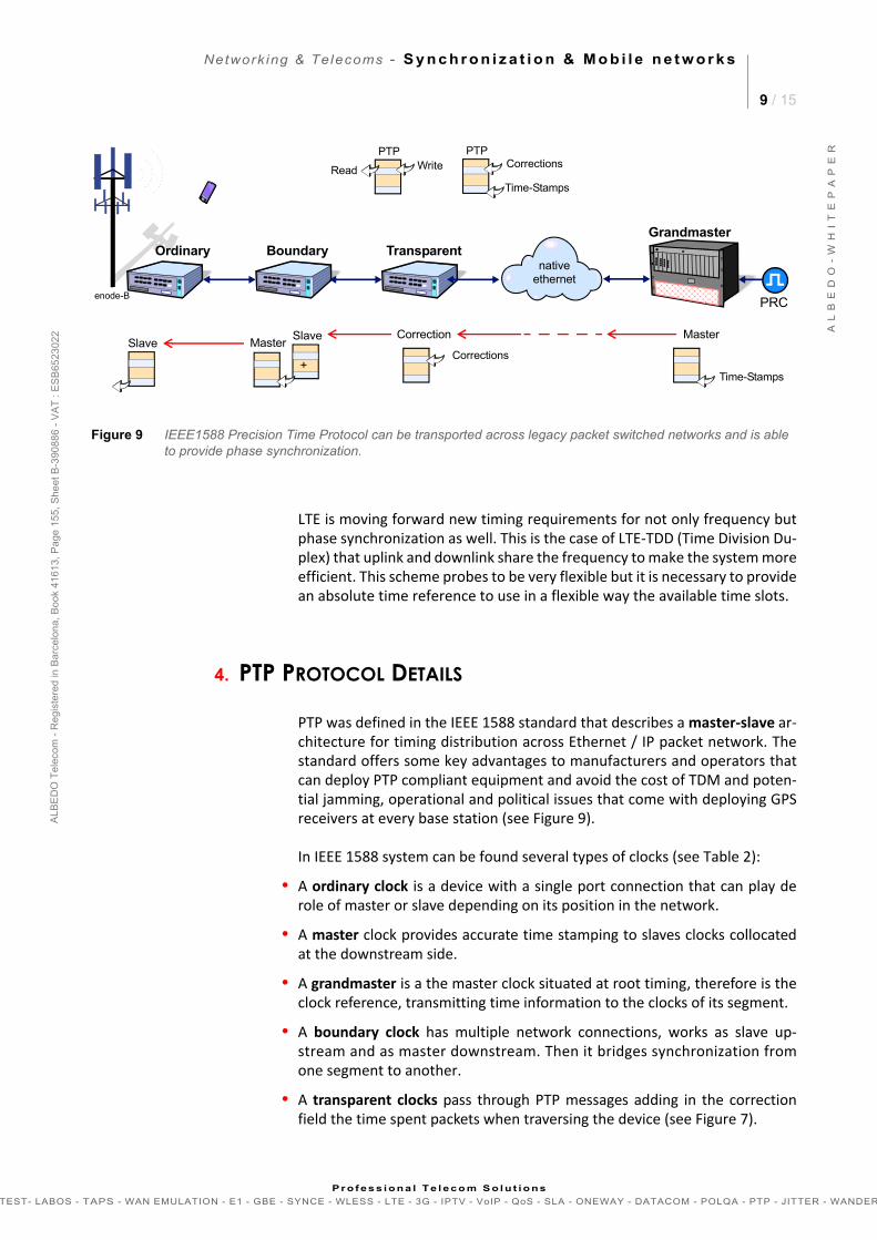
PTP was defined in the IEEE 1588 standard that describes a master-slave ar-chitecture for timing distribution across Ethernet / IP packet network. Thestandard offers some key advantages to manufacturers and operators thatcan deploy PTP compliant equipment and avoid the cost of TDM and poten-tial jamming, operational and political issues that come with deploying GPSreceivers at every base station (see Figure 9).
In IEEE 1588 system can be found several types of clocks (see Table 2):
• A ordinary clock is a device with a single port connection that can play derole of master or slave depending on its position in the network.
• A master clock provides accurate time stamping to slaves clocks collocatedat the downstream side.
• A grandmaster is a the master clock situated at root timing, therefore is theclock reference, transmitting time information to the clocks of its segment.
• A boundary clock has multiple network connections, works as slave up-stream and as master downstream. Then it bridges synchronization fromone segment to another.
• A transparent clocks pass through PTP messages adding in the correctionfield the time spent packets when traversing the device (see Figure 7).
Figure 9 IEEE1588 Precision Time Protocol can be transported across legacy packet switched networks and is able to provide phase synchronization.
SlaveMaster
enode-BPRC
BoundaryOrdinaryGrandmaster
Transparent
Slave Correction
ethernetnative
Master
+Corrections
Time-Stamps
Time-Stamps
CorrectionsPTP
WritePTP
Read

Network ing & Telecoms - S y n c h r o n i z a t i o n & M o b i l e n e t w o r k s
10 / 15
A L
B E
D O
- W
H I
T E
P A
P E
R
AL B
ED
O T
ele
com
- R
eg
iste
r ed
in B
arc
elo
na
, B
oo
k 41
61
3, P
age
15
5,
Sh
ee
t B-3
9 08
86
- V
AT
: E
SB
652
30
22
Pr o f es s i ona l Te l eco m S o l u t io ns
TEST- LABOS - TAPS - WAN EMULATION - E1 - GBE - SYNCE - WLESS - LTE - 3G - IPTV - VoIP - QoS - SLA - ONEWAY - DATACOM - POLQA - PTP - JITTER - WANDER
By using boundary and transparent clock functions in the synchronizationchain, the effects of latency and packet delay variation are minimized. Mas-ter and slaves do exchange packets containing short messages to measureand eliminate phase errors.
Using IEEE 1588v2 reduces the number of required GPS antennas and the as-sociated cost, and it enables operators to distribute phase synchronization tosites where GPS is difficult to deploy.
PTP Profiles
IEEE-1588 2008 introduced the Profile concept as a set of PTP optional fea-tures to support different types of applications. For instance a PTP profilemay define Path Delay Control, the transport mechanisms required, nodetypes, message exchange rate, unicast or multicast protocol. Profiles facili-tate the interoperability between nodes and the deployment of PTP acrosstelecoms networks.
Table 2IEEE 1588v2 Device Description
Clock Description OperationOrdinary Single-port device that can be a master or slave clock Read/Write time stamps
Grandmaster Ordinary clock that manages the reference time Write time stamps and responds time request from other clocks
Slave Ordinary clock that keeps synchronized to the masters and provides synchronization to its clients
Write time stamps and responds time request from other clocks
Boundary Multi-port device that can be a master or slave clock Read/Write time stampsTransparent(end-to-end)
Multi-port device that is not a master or slave clock but a bridge between both forwarding / correcting PTP messages Write corrections
Transparent(peer-to-peer)
Multi-port device that is not a master or slave clock but a bridge between both forwarding / correcting Sync and Follow-up messages Write corrections
Figure 10 Ether.Sync or Ether.Genius executing the ITU-T Y.1564 (eSAM) to verify the KPI that affect PTP flows.
enode-BPRC
PTP SlavePTP Grandmaster
ethernetnative
e.tester e.tester
Y.1564 & RFC2544 Multistream
Network ing & Telecoms - S y n c h r o n i z a t i o n & M o b i l e n e t w o r k s
11 / 15
A L
B E
D O
- W
H I
T E
P A
P E
R
AL B
ED
O T
ele
com
- R
eg
iste
r ed
in B
arc
elo
na
, B
oo
k 41
61
3, P
age
15
5,
Sh
ee
t B-3
9 08
86
- V
AT
: E
SB
652
30
22
Pr o f es s i ona l Te l eco m S o l u t io ns
TEST- LABOS - TAPS - WAN EMULATION - E1 - GBE - SYNCE - WLESS - LTE - 3G - IPTV - VoIP - QoS - SLA - ONEWAY - DATACOM - POLQA - PTP - JITTER - WANDER
5. INSTALLATION, TURN-UP & MAINTENANCE OF PTP
Service Activation
The first step it the analysis of KPI of the network that has to transport PTPstreams in terms of capacity and quality. They may determine the success -orfailure- of the implementation. With Ether.Genius executing eSAM can besimulated a PTP service including the generation of background traffic withdifferent traffic profiles.
The basic purpose of eSAM is to check that PTP frames are transported withthe required performance in terms of Frame Total Delay (FTD), Frame DelayVariation (FDV), Frame Loss Ratio (FLR) and Availability to make sure that theSLA reserved for PTP messages is preserved by the network when requiredto do so (see Figure 10).
PTP test and Measurements
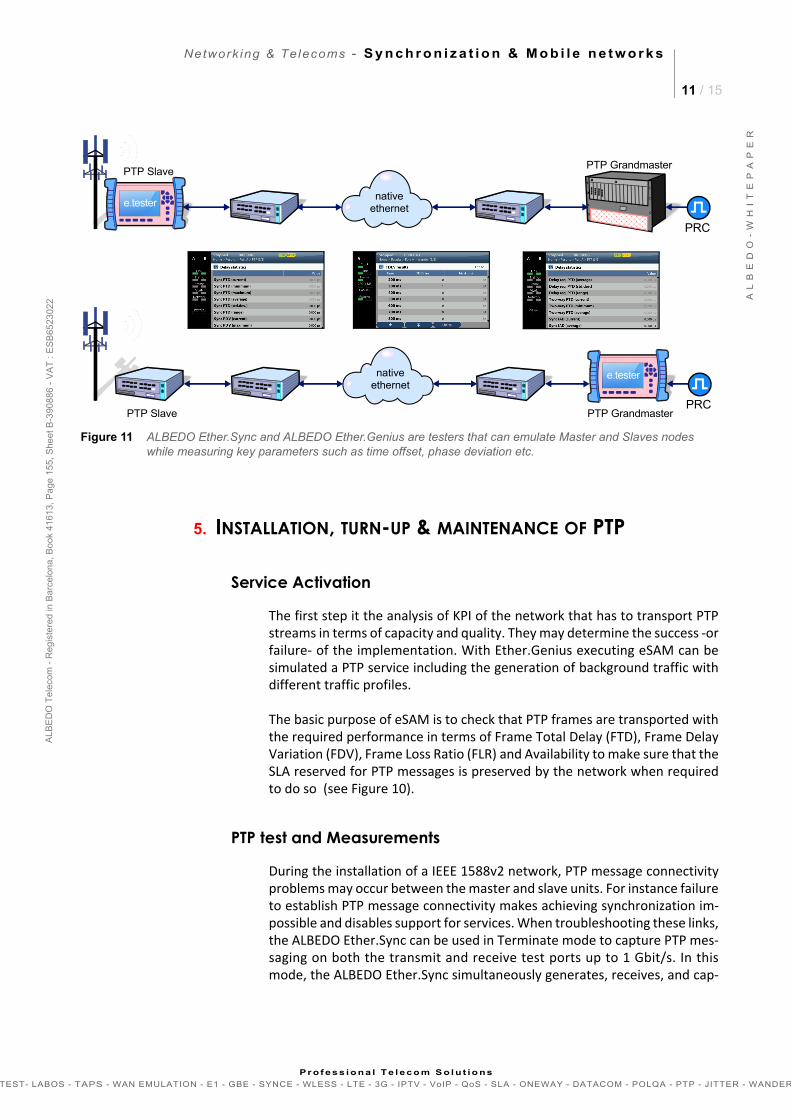
During the installation of a IEEE 1588v2 network, PTP message connectivityproblems may occur between the master and slave units. For instance failureto establish PTP message connectivity makes achieving synchronization im-possible and disables support for services. When troubleshooting these links,the ALBEDO Ether.Sync can be used in Terminate mode to capture PTP mes-saging on both the transmit and receive test ports up to 1 Gbit/s. In thismode, the ALBEDO Ether.Sync simultaneously generates, receives, and cap-
e.tester
Figure 11 ALBEDO Ether.Sync and ALBEDO Ether.Genius are testers that can emulate Master and Slaves nodes while measuring key parameters such as time offset, phase deviation etc.
PRCPTP Slave PTP Grandmaster
ethernetnative
e.tester
PRC
PTP SlavePTP Grandmaster
ethernetnative
Network ing & Telecoms - S y n c h r o n i z a t i o n & M o b i l e n e t w o r k s
12 / 15
A L
B E
D O
- W
H I
T E
P A
P E
R
AL B
ED
O T
ele
com
- R
eg
iste
r ed
in B
arc
elo
na
, B
oo
k 41
61
3, P
age
15
5,
Sh
ee
t B-3
9 08
86
- V
AT
: E
SB
652
30
22
Pr o f es s i ona l Te l eco m S o l u t io ns
TEST- LABOS - TAPS - WAN EMULATION - E1 - GBE - SYNCE - WLESS - LTE - 3G - IPTV - VoIP - QoS - SLA - ONEWAY - DATACOM - POLQA - PTP - JITTER - WANDER
tures PTP messages on the circuit under test. Users can quickly identify high-er layer protocol issues that may be associated with PTP messages and/orprovisioning (see Figure 11).
The protocol PTP is designed to work under network conditions includinghighly occupied networks. When there is a lot of contention the routing andswitching of PTP messages could therefore be affected causing potential badeffects like packet delay variation in PTP messages will ultimately affect syn-chronization because it depends upon consistently timed message recep-tion. Both ALBEDO Ether.Sync and ALBEDO Ether.Genius can emulate dataplane traffic (up to eight streams) while PTP messages are transmitted simul-taneously. Under these conditions, field engineers can verify if the new orthe existing PTP network are capable to operate properly under many differ-ent load scenarios.
Network Impairments
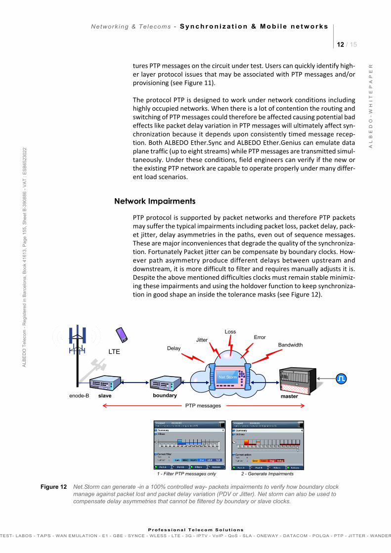
PTP protocol is supported by packet networks and therefore PTP packetsmay suffer the typical impairments including packet loss, packet delay, pack-et jitter, delay asymmetries in the paths, even out of sequence messages.These are major inconveniences that degrade the quality of the synchroniza-tion. Fortunately Packet jitter can be compensate by boundary clocks. How-ever path asymmetry produce different delays between upstream anddownstream, it is more difficult to filter and requires manually adjusts it is.Despite the above mentioned difficulties clocks must remain stable minimiz-ing these impairments and using the holdover function to keep synchroniza-tion in good shape an inside the tolerance masks (see Figure 12).
LTE
enode-B
ethernetasyncNet.Storm
master
Bandwidth
ErrorLoss
Jitter
Delay
Figure 12 Net.Storm can generate -in a 100% controlled way- packets impairments to verify how boundary clock manage against packet lost and packet delay variation (PDV or Jitter). Net storm can also be used to compensate delay asymmetries that cannot be filtered by boundary or slave clocks.
slave
PTP messages
1 - Filter PTP messages only 2 - Generate Impairments
boundary
Network ing & Telecoms - S y n c h r o n i z a t i o n & M o b i l e n e t w o r k s
13 / 15
A L
B E
D O
- W
H I
T E
P A
P E
R
AL B
ED
O T
ele
com
- R
eg
iste
r ed
in B
arc
elo
na
, B
oo
k 41
61
3, P
age
15
5,
Sh
ee
t B-3
9 08
86
- V
AT
: E
SB
652
30
22
Pr o f es s i ona l Te l eco m S o l u t io ns
TEST- LABOS - TAPS - WAN EMULATION - E1 - GBE - SYNCE - WLESS - LTE - 3G - IPTV - VoIP - QoS - SLA - ONEWAY - DATACOM - POLQA - PTP - JITTER - WANDER
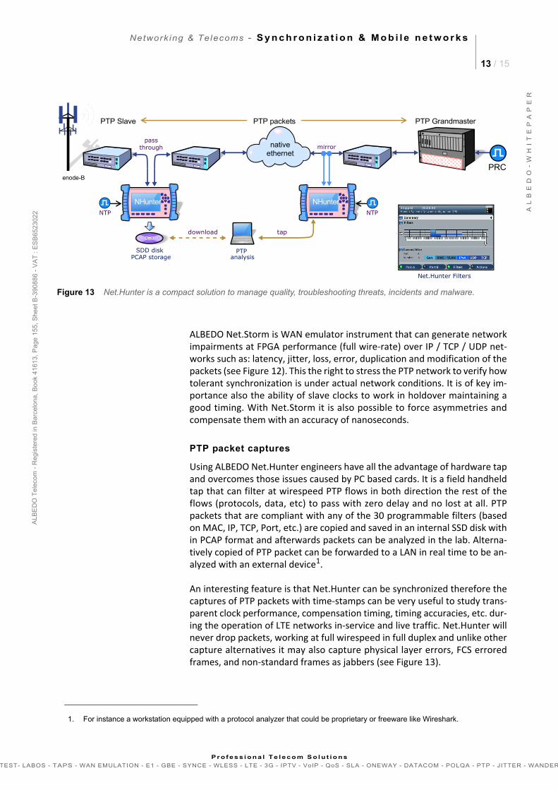
ALBEDO Net.Storm is WAN emulator instrument that can generate networkimpairments at FPGA performance (full wire-rate) over IP / TCP / UDP net-works such as: latency, jitter, loss, error, duplication and modification of thepackets (see Figure 12). This the right to stress the PTP network to verify howtolerant synchronization is under actual network conditions. It is of key im-portance also the ability of slave clocks to work in holdover maintaining agood timing. With Net.Storm it is also possible to force asymmetries andcompensate them with an accuracy of nanoseconds.
PTP packet captures
Using ALBEDO Net.Hunter engineers have all the advantage of hardware tapand overcomes those issues caused by PC based cards. It is a field handheldtap that can filter at wirespeed PTP flows in both direction the rest of theflows (protocols, data, etc) to pass with zero delay and no lost at all. PTPpackets that are compliant with any of the 30 programmable filters (basedon MAC, IP, TCP, Port, etc.) are copied and saved in an internal SSD disk within PCAP format and afterwards packets can be analyzed in the lab. Alterna-tively copied of PTP packet can be forwarded to a LAN in real time to be an-alyzed with an external device1.
An interesting feature is that Net.Hunter can be synchronized therefore thecaptures of PTP packets with time-stamps can be very useful to study trans-parent clock performance, compensation timing, timing accuracies, etc. dur-ing the operation of LTE networks in-service and live traffic. Net.Hunter willnever drop packets, working at full wirespeed in full duplex and unlike othercapture alternatives it may also capture physical layer errors, FCS erroredframes, and non-standard frames as jabbers (see Figure 13).
1. For instance a workstation equipped with a protocol analyzer that could be proprietary or freeware like Wireshark.
Figure 13 Net.Hunter is a compact solution to manage quality, troubleshooting threats, incidents and malware.
PTP analysis
SDD disk
NTP
tapdownload
PCAP storage
Net.Hunter Filters
enode-B
PTP Slave
PRC
PTP Grandmaster
ethernetnative
NHunter
passmirror
NHunter
through
NTP
PTP packets
Network ing & Telecoms - S y n c h r o n i z a t i o n & M o b i l e n e t w o r k s
14 / 15
A L
B E
D O
- W
H I
T E
P A
P E
R
AL B
ED
O T
ele
com
- R
eg
iste
r ed
in B
arc
elo
na
, B
oo
k 41
61
3, P
age
15
5,
Sh
ee
t B-3
9 08
86
- V
AT
: E
SB
652
30
22
Pr o f es s i ona l Te l eco m S o l u t io ns
TEST- LABOS - TAPS - WAN EMULATION - E1 - GBE - SYNCE - WLESS - LTE - 3G - IPTV - VoIP - QoS - SLA - ONEWAY - DATACOM - POLQA - PTP - JITTER - WANDER
Selected Bibliography
[1] Sargento S., Valadas R., Gonçalves J., Sousa H., IP-Based Access Networks for Broadband Multimedia Services, IEEE Communications Magazine, February 2003, pp. 146-154.
[2] Ferrant J., Gilson M., Jobert S., Mayer M., Ouellette M., Montini L., Rodrigues S., Ruffini S., Synchronous Ethernet: A Method to Transport Synchronization, IEEE Communications Magazine, September 2008, pp. 126-134.
[3] Vainshtein A., Stein YJ., Structure-Agnostic Time Division Multiplexing (TDM) over Packet (SAToP), IETF Request For Comments RFC 4553, Jun. 2006.
[4] Vainshtein A., Sasson I., Metz E., Frost T., Pate P., Structure-Aware Time Division Multiplexed (TDM) Circuit Emu-lation Service over Packet Switched Network (CESoPSN), IETF Request For Comments RFC 5086, Dec. 2007.
[5] ITU-T Rec. Y.1413, TDM-MPLS network interworking - User plane interworking, March 2004.
[6] ITU-T Rec. Y.1453, TDM-IP interworking - User plane interworking, March 2006.
[7] ITU-T Rec. G.8261, Timing and Synchronization Aspects in Packet Networks, February 2008.
[8] ITU-T Rec. G.8262, Timing Characteristics of Synchronous Ethernet Equipment Slave Clock (EEC), August 2007.
[9] ITU-T Rec. G.8264, Distribution of Timing Through Packet Networks, February 2008.
[10] Metro Ethernet Forum Technical Specification MEF 8, Implementation Agreement for the Emulation of PDH Cir-cuits over Metro Ethernet Networks, October 2004.
[11] Metro Ethernet Forum Technical Specification MEF 18, Abstract Test Suite for Circuit Emulation Services over Ethernet based on MEF 8, May 2007.
[12] Considerations for Synchronization in NGN Packet-Based Mobile Backhaul Networks OSP Magazine Zeev Draer
aims+ LEARN from business models and case studies
+ UNDERSTAND the potential of interoperability with legacy services
+ EXPERIENCE specialised synchronization network solutions
+ ASSESS different solutions for installation and maintenance
ALBEDO Telecom
ALBEDO Telecom delivers solutions that enable Telecom infrastructures of al l sizes to troubleshoot, monitor, and migrate mission crit ical networks.
From the desktop to the data centre, from Access Network, Ethernet, Sync-E, PTP, Optical backbones, LTE, VoIP or IPTV applications.
On local segments and across distributed networks, ALBEDO enable Telecom Organizations, Telecom Instal lers, Network Operators, Internet Service Providers and Contents Suppliers to quickly check the health of your network, verify SLA, or f ind and fix problems.
Benefits
Results . The ALBEDO Telecom to help Telecom industry to make the most of the investment on network infrastructure.
Expertise. ALBEDO trainers, auditors, engineers and consultants provide industry-leading knowledge to address the unique needs of customers.
Integration. ALBEDO integrates disparate telecom resources and applications, realizing new business efficiencies.
Agility . ALBEDO increases the abil ity of customers to respond quickly to new market opportunities and requirements.
Coverage. ALBEDO offers solutions that faci l itates the migration and the rol l-out to new telecom architectures.
in Test we TrustAmericas (US & Canada)
[email protected]+1 647 233 7353
+34 610 292 763
+41 (0)31 853 14 56
World [email protected](find out our nearest rep)
test
+ m
ea
su
rem
en
t +
WA
N e
mu
lati
on
+ p
acke
t ca
ptu
re +
syn
ch
ron
iza
tio
n +
co
nsu
lta
ncy
+91-98110 55459
+44 (0) 1865 601008


![wless LAN.ppt [modalit compatibilit ])](https://img.dokumen.tips/doc/110x75/62b11890c4293a6a595e82ac/wless-lanppt-modalit-compatibilit-.jpg)