Embed Size (px)
Citation preview

Installation Guide PTP 850E System Release 10.9

Page 2 of 99
Accuracy
While reasonable efforts have been made to assure the accuracy of this document, Cambium Networks assumes no liability resulting from any inaccuracies or omissions in this document, or from use of the information obtained herein. Cambium reserves the right to make changes to any products described herein to improve reliability, function, or design, and reserves the right to revise this document and to make changes from time to time in content hereof with no obligation to notify any person of revisions or changes. Cambium does not assume any liability arising out of the application or use of any product, software, or circuit described herein; neither does it convey license under its patent rights or the rights of others. It is possible that this publication may contain references to, or information about Cambium products (machines and programs), programming, or services that are not announced in your country. Such references or information must not be construed to mean that Cambium intends to announce such Cambium products, programming, or services in your country.
Copyrights
This document, Cambium products, and 3rd Party software products described in this document may include or describe copyrighted Cambium and other 3rd Party supplied computer programs stored in semiconductor memories or other media. Laws in the United States and other countries preserve for Cambium, its licensors, and other 3rd Party supplied software certain exclusive rights for copyrighted material, including the exclusive right to copy, reproduce in any form, distribute and make derivative works of the copyrighted material. Accordingly, any copyrighted material of Cambium, its licensors, or the 3rd Party software supplied material contained in the Cambium products described in this document may not be copied, reproduced, reverse engineered, distributed, merged or modified in any manner without the express written permission of Cambium. Furthermore, the purchase of Cambium products shall not be deemed to grant either directly or by implication, estoppel, or otherwise, any license under the copyrights, patents or patent applications of Cambium or other 3rd Party supplied software, except for the normal non-exclusive, royalty free license to use that arises by operation of law in the sale of a product.
Restrictions
Software and documentation are copyrighted materials. Making unauthorized copies is prohibited by law. No part of the software or documentation may be reproduced, transmitted, transcribed, stored in a retrieval system, or translated into any language or computer language, in any form or by any means, without prior written permission of Cambium.
License Agreements
The software described in this document is the property of Cambium and its licensors. It is furnished by express license agreement only and may be used only in accordance with the terms of such an agreement.
High Risk Materials
Cambium and its supplier(s) specifically disclaim any express or implied warranty of fitness for any high risk activities or uses of its products including, but not limited to, the operation of nuclear facilities, aircraft navigation or aircraft communication systems, air traffic control, life support, or weapons systems (“High Risk Use”). Any High Risk is unauthorized, is made at your own risk and you shall be responsible for any and all losses, damage or claims arising out of any High Risk Use.
© 2019 Cambium Networks Limited. All Rights Reserved.

Page 3 of 99
Table of Contents Before You Start ...................................................................................................................... 8
Important Notes .................................................................................................................................... 8 Feedback .................................................................................................................................................. 8
Problems and warranty ........................................................................................................................... 8 Reporting problems ............................................................................................................................ 8 Repair and service ............................................................................................................................... 8 Hardware warranty ............................................................................................................................. 9
Security advice ............................................................................................................................................ 9
Warnings, cautions, and notes ............................................................................................................. 9 Warnings ................................................................................................................................................... 9 Cautions .................................................................................................................................................. 10 Notes ........................................................................................................................................................ 10
Caring for the environment ................................................................................................................. 10 In EU countries .................................................................................................................................... 10 In non-EU countries ............................................................................................................................ 11
Safety Precautions & Declared Material .......................................................................................... 11 General Equipment Precautions ................................................................................................... 11 Précautions générales relatives à l'équipement .................................................................. 12 Allgemeine Vorsichtsmaßnahmen für die Anlage .............................................................. 12
Pre-Installation Instructions.................................................................................................................. 12 Packing ..................................................................................................................................................... 12 Transportation and Storage .......................................................................................................... 12 Unpacking .............................................................................................................................................. 13 Inspection ............................................................................................................................................... 13 Torque Requirements ...................................................................................................................... 13
Product Hardware Description .......................................................................................................... 14
PTP 850E Hardware Overview .......................................................................................................... 14
PTP 850E Interfaces ................................................................................................................................15
PoE Injector ................................................................................................................................................. 16 PoE Injector Interfaces ..................................................................................................................... 17
System Components ............................................................................................................................... 17
Adaptors and Installation Kits ............................................................................................................. 17
Antenna Connection ............................................................................................................................... 18
Power Specifications .............................................................................................................................. 18 Power Input Specifications ........................................................................................................... 18 Power Consumption Specifications .......................................................................................... 19 Power Connection Options ........................................................................................................... 19 PoE Injector Power Input – Standard PoE ............................................................................ 19 PoE Injector Power Input – Passive PoE ................................................................................ 19 Important Notes!................................................................................................................................. 19
Environmental Specifications ............................................................................................................ 20
Cable Installation and Grounding .................................................................................... 21
Minimum and Maximum Cable Diameter ...................................................................................... 21

Page 4 of 99
Grounding the Cables.............................................................................................................................. 21
Grounding the PTP 850E Unit .......................................................................................................... 24
Power Source ............................................................................................................................................ 25
Surge Protection ...................................................................................................................................... 25
Available Cable Options ....................................................................................................................... 26 Fiber Optic Cables – Single Mode............................................................................................. 26 Fiber Optic Cables – Mulit Mode ...................................... Error! Bookmark not defined. MPO-MPO Cables for QSFP Links .................................. Error! Bookmark not defined. DC Cable and Connector .............................................................................................................. 26 Extension Cable for Protection and XPIC ........................................................................... 26 Ethernet Cable and Specifications ........................................................................................... 26 Outdoor Ethernet Cable Specifications ................................................................................. 27 Outdoor DC Cable Specifications ............................................................................................. 28
Securing the Cables ............................................................................................................................... 29
Special Instructions for use of Glands .......................................................................................... 29 General Installation Procedure ................................................................................................... 30
Connecting an Optical Fiber Cable and SFP ............................................................................. 36 Types of SFPs ..................................................................................................................................... 36 Connecting Optical Fiber to SFPs ............................................................................................ 37
Connecting a DC Power Cable ......................................................................................................... 42
Connecting the Ethernet Cable ........................................................................................................ 45 Preparing the Ethernet Cable and Plug-in Field ............................................................... 45 Preparing the Ethernet Cable Already Assembled .......................................................... 48 Connection of Ethernet Cable to PTP 850E ....................................................................... 48 Connection of Extension Cable to PTP 850E .......................................................................51
PoE Injector Installation and Connection ....................................................................53
PoE Injector Cable Connection ........................................................................................................ 53
PoE Injector Grounding ........................................................................................................................ 54
PoE Injector Wall Mount Installation .............................................................................................. 54
PoE Injector Pole Mount Installation .............................................................................................. 56
PoE Injector 19” Rack Installation .................................................................................................... 57
PoE Injector ETSI Rack Installation ................................................................................................ 58
Installation Procedure and Antenna Alignment – 1+0 with 43 dBi Flat Antenna and Alignment Device ................................................................................61
Pole Mount Assembly and Installation .......................................................................................... 64
Wall Mount Assembly and Installation ......................................................................................... 66 Procedure .............................................................................................................................................. 67
Attaching the PTP 850E to the Installation and Alignment Device .............................. 68
Performing Antenna Alignment Using the Enhanced Alignment Kit ........................... 69 Adjusting the Antenna Azimuth ................................................................................................ 69 Adjusting the Antenna Elevation .............................................................................................. 72

Page 5 of 99
Direct Mount Configurations ........................................................................................... 76
1+0 Direct Mount Installation ............................................................................................................. 76
1+1 HSB and 2+0 Single Polarization .............................................................................................. 79
2+0 Direct Mount Dual Polarization ............................................................................................... 83
2+0 Single Polarization ......................................................................................................................... 84
2+0 Dual Polarization ............................................................................................................................ 88
Multiband Configurations ................................................................................................. 90
Multiband with PTP 850E and PTP 820C with 2+0 Single Polarization...................... 90
Multiband with PTP 850E and PTP 820C with 2+0 Dual Polarization ......................... 93
Multiband with PTP 850E and 1+0 PTP 820S ........................................................................... 95

Page 6 of 99
List of Figures Figure 1: PTP 850E Rear View (Left) and Front View (Right) .................................................................. 14
Figure 2: Cable Gland Construction ........................................................................................................ 14
Figure 3: PTP 850E Interfaces – ESE ....................................................................................................... 15
Figure 4: PoE Injector ............................................................................................................................. 16
Figure 5: PoE Injector Ports .................................................................................................................... 17
Figure 6: PTP 850E .................................................................................................................................. 17
Figure 7: OMT ......................................................................................................................................... 17
Figure 8: Cable Grounding Kit ................................................................................................................ 21
Figure 9: Cable Design ............................................................................................................................ 27
Figure 10: Tightening the Front Portion of the Gland ............................................................................ 35
Figure 11: Tightening the Rear Portion of the Gland ............................................................................. 35
Figure 12 Installation and Alignment Device – Azimuth and Elevation Adjustment Tools .................... 61
Figure 13 Installation and Alignment Device – Azimuth Range (Pole Mount) ....................................... 62
Figure 14 Installation and Alignment Device – Delivery Elevation (22° Downward) ............................. 63
Figure 15 Installation and Alignment Device – Highest Elevation (45° Upward) ................................... 63
Figure 16: Horizontal Polarization – Radio and Installation and Alignment Kit ..................................... 68
Figure 17: Horizontal Polarization – Screws Location ............................................................................ 68
Figure 18: Vertical Polarization – Radio and Installation and Alignment Kit .......................................... 68
Figure 19: Vertical Polarization – Screws Location ................................................................................. 68
Figure 20: Horizontal Polarization .......................................................................................................... 80
Figure 21: Vertical Polarization .............................................................................................................. 81
Figure 38: Horizontal Polarization .......................................................................................................... 86
Figure 39: Vertical Polarization .............................................................................................................. 86
Figure 40: PTP 820STwist Orientation .................................................................................................... 98

Page 7 of 99
List of Tables Table 1: PTP 850E Accessories ............................................................................................................... 17
Table 2: PoE Injector .............................................................................................................................. 18
Table 3: QSFP Accessories ......................................................................... Error! Bookmark not defined.
Table 4: Cable Grounding Kit .................................................................................................................. 21
Table 5: Ethernet Cable Color Code ....................................................................................................... 27
Table 6: Outdoor Ethernet Cable Electrical Requirements .................................................................... 27
Table 7: Outdoor Ethernet Cable Mechanical/Environmental Requirements ....................................... 28
Table 8: Outdoor DC Cable Electrical Requirements .............................................................................. 28
Table 9: Outdoor DC Cable Mechanical/Environmental Requirements ................................................. 28
Table 10: Glands Kit ................................................................................................................................ 29
Table 11: Gland Cap ............................................................................................................................... 29
Table 12: QSFP – SFP + Adapter ............................................................................................................. 36
Table 13QSFP Module Recommendations ................................................ Error! Bookmark not defined.
Table 14: SFP Module Recommendations.............................................................................................. 37
Table 15: CSFP Module Recommendations ........................................................................................... 37
Table 16: SFP Module Recommendations for Third Party Equipment ...... Error! Bookmark not defined.
Table 17: Approved 10 GbE SFP+ Modules ............................................... Error! Bookmark not defined.
Table 18: Materials for Preparing Ethernet Data Cables ........................................................................ 45
Table 19: Multiband Antenna Part number ........................................................................................... 90

Page 8 of 99
Before You Start
Important Notes • For the warranty to be honored, install the unit in accordance with the instructions in this
manual.
• Any changes or modifications of equipment not expressly approved by the manufacturer could void the user’s authority to operate the equipment and the warranty for such equipment.
• PTP 850E is intended for installation in a restricted access location.
• PTP 850E must be installed and permanently connected to protective earth by qualified service personnel in accordance with applicable national electrical codes.
• Before starting an installation, use a leveler to make sure that the poles are 100% vertical. You need to check both sides of each pole at 90 degrees separation.
Feedback
We appreciate feedback from the users of our documents. This includes feedback on the
structure, content, accuracy, or completeness of our documents. Send feedback to
Problems and warranty
Reporting problems
If any problems are encountered when installing or operating this equipment, follow this
procedure to investigate and report:
1 Search this document and the software release notes of supported releases.
2 Visit the support website.
3 Ask for assistance from the Cambium product supplier.
4 Gather information from affected units, such as any available diagnostic downloads.
5 Escalate the problem by emailing or telephoning support.
Repair and service
If unit failure is suspected, obtain details of the Return Material Authorization (RMA) process
from the support website.

Page 9 of 99
Hardware warranty
Cambium’s standard hardware warranty is for one (1) year from date of shipment from
Cambium Networks or a Cambium distributor. Cambium Networks warrants that hardware
will conform to the relevant published specifications and will be free from material defects in material and workmanship under normal use and service. Cambium shall within this time,
at its own option, either repair or replace the defective product within thirty (30) days of
receipt of the defective product. Repaired or replaced product will be subject to the original
warranty period but not less than thirty (30) days.
To register PTP products or activate warranties, visit the support website. For warranty
assistance, contact the reseller or distributor.
Caution
Using non-Cambium parts for repair could damage the equipment or void warranty.
Contact Cambium for service and repair instructions.
Portions of Cambium equipment may be damaged from exposure to electrostatic
discharge. Use precautions to prevent damage.
Security advice Cambium PTP 850 Networks systems and equipment provide security parameters that can be configured by the operator based on their operating environment. Cambium
recommends setting and using these parameters following industry recognized security
practices. Security aspects to be considered are protecting the confidentiality, integrity, and availability of information and assets. Assets include the ability to communicate, information
about the nature of the communications, and information about the parties involved.
In certain instances, Cambium makes specific recommendations regarding security practices, however the implementation of these recommendations and final responsibility
for the security of the system lies with the operator of the system.
Warnings, cautions, and notes The following describes how warnings and cautions are used in this document and in all
documents of the Cambium Networks document set.
Warnings
Warnings precede instructions that contain potentially hazardous situations. Warnings are
used to alert the reader to possible hazards that could cause loss of life or physical injury. A
warning has the following format:
Warning
Warning text and consequence for not following the instructions in the warning.

Page 10 of 99
Cautions
Cautions precede instructions and are used when there is a possibility of damage to
systems, software, or individual items of equipment within a system. However, this damage
presents no danger to personnel. A caution has the following format:
Caution
Caution text and consequence for not following the instructions in the caution.
Notes
A note means that there is a possibility of an undesirable situation or provides additional
information to help the reader understand a topic or concept. A note has the following format:
Note
Note text.
Caring for the environment The following information describes national or regional requirements for the disposal of
Cambium Networks supplied equipment and for the approved disposal of surplus
packaging.
In EU countries
The following information is provided to enable regulatory compliance with the European
Union (EU) directives identified and any amendments made to these directives when using
Cambium equipment in EU countries.
Disposal of Cambium equipment European Union (EU) Directive 2002/96/EC Waste Electrical and Electronic Equipment
(WEEE)
Do not dispose of Cambium equipment in landfill sites. For disposal instructions, refer to
http://www.cambiumnetworks.com/support.
Page 11 of 99
Disposal of surplus packaging Do not dispose of surplus packaging in landfill sites. In the EU, it is the individual recipient’s
responsibility to ensure that packaging materials are collected and recycled according to
the requirements of EU environmental law.
In non-EU countries
In non-EU countries, dispose of Cambium equipment and all surplus packaging in
accordance with national and regional regulations.
Safety Precautions & Declared Material
General Equipment Precautions
To avoid malfunctioning or personnel injuries, equipment or accessories/kits/plug-in unit installation, requires qualified and trained personnel. Changes or modifications not expressly approved by Cambium Networks could void the user's authority to operate the equipment.
Where special cables, shields, adapters and grounding kits are supplied or described in this manual, these items must be used, to comply with the FCC regulations.
Use of controls, adjustments, or performing procedures other than those specified herein, may result in hazardous radiation exposure.
Use of controls, adjustments, or performing procedures other than those specified herein, may result in hazardous radiation exposure.
When working with an PTP 820E, note the following risk of electric shock and energy hazard:
Disconnecting one power supply disconnects only one power supply module. To isolate the unit completely, disconnect all power supplies.
Machine noise information order - 3. GPSGV, the highest sound pressure level amounts to 70 dB (A) or less, in accordance with ISO EN 7779.
Static electricity may cause body harm, as well as harm to electronic components inside the device. Anyone responsible for the installation or maintenance of the PTP 820E must use an ESD Wrist Strap. ESD protection measures must be observed when touching the unit. To prevent damage, before touching components inside the device, all electrostatic must be discharged from both personnel and tools.
In Norway and Sweden:
Equipment connected to the protective earthing of the building installation through the mains connection or through other equipment with a connection to protective earthing – and to a cable distribution system using coaxial cable, may in some circumstances create a fire hazard. Connection to a cable distribution system has therefore to be provided through a device providing electrical isolation below a certain frequency range (galvanic isolator, see EN 60728-11).
Utstyr som er koplet til beskyttelsesjord via nettplugg og/eller via annet jordtilkoplet utstyr – og er tilkoplet et kabel-TV nett, kan forårsake brannfare. For å unngå dette
Page 12 of 99
skal det ved tilkopling av utstyret til kabel-TV nettet installeres en galvanisk isolator mellom utstyret og kabel- TV nettet.
Utrustning som är kopplad till skyddsjord via jordat vägguttag och/eller via annan utrustning och samtidigt är kopplad till kabel-TV nät kan i vissa fall medfőra risk főr brand. Főr att undvika detta skall vid anslutning av utrustningen till kabel-TV nät galvanisk isolator finnas mellan utrustningen och kabel-TV nätet
Précautions générales relatives à l'équipement
L’utilisation de commandes ou de réglages ou l'exécution de procédures autres que celles spécifiées dans les présentes peut engendrer une exposition dangereuse aux rayonnements.
L’usage de PTP 820E s’accompagne du risque suivant d'électrocution et de danger électrique : le débranchement d'une alimentation électrique ne déconnecte qu'un module d'alimentation électrique. Pour isoler complètement l'unité, il faut débrancher toutes les alimentations électriques.
Bruit de machine d’ordre - 3. GPSGV, le plus haut niveau de pression sonore s'élève à 70 dB (A) au maximum, dans le respect de la norme ISO EN 7779.
Allgemeine Vorsichtsmaßnahmen für die Anlage
Wenn andere Steuerelemente verwendet, Einstellungen vorgenommen oder Verfahren durchgeführt werden als die hier angegebenen, kann dies gefährliche Strahlung verursachen.
Beachten Sie beim Arbeiten mit PTP 820E das folgende Stromschlag- und Gefahrenrisiko: Durch Abtrennen einer Stromquelle wird nur ein
Stromversorgungsmodul abgetrennt. Um die Einheit vollständig zu isolieren, trennen Sie alle Stromversorgungen ab.
Maschinenlärminformations-Verordnung - 3. GPSGV, der höchste Schalldruckpegel beträgt 70 dB(A) oder weniger gemäß EN ISO 7779.
Pre-Installation Instructions
Packing The equipment should be packed and sealed in moisture absorbing bags.
Transportation and Storage The equipment cases are prepared for shipment by air, truck, railway and sea, suitable for handling by forklift trucks and slings. The cargo must be kept dry during transportation, in accordance with ETS 300 019-1-2, Class 2.3. For sea-transport, deck-side shipment is not permitted. Carrier-owned cargo containers should be used.
It is recommended that the equipment be transported to the installation site in its original packing case.
If intermediate storage is required, the packed equipment must be stored in a dry and cool environment, and out of direct sunlight, in accordance with ETS 300 019-1-1, Class 1.2.

Page 13 of 99
Unpacking The equipment is packed in sealed plastic bags and moisture absorbing bags are inserted. Any separate sensitive product, i.e. printed boards, are packed in anti-static handling bags. The equipment is further packed in special designed cases.
Marking is done according to standard practice unless otherwise specified by customers. The following details should be marked:
• Customers address
• Contract No
• Site name (if known)
• Case No
Inspection Check the packing lists and ensure that correct parts numbers quantities of goods have arrived. Inspect for any damage on the cases and equipment. Report any damage or discrepancy to a Cambium representative, by e-mail or fax.
Torque Requirements
When performing the procedures described in this document, make sure to use the following torque according to the type of screws used in the procedure: • M8 screws: 20 Nm • M3 screws (used with PTP 820C and PTP 820S twist): 0.6 Nm • #4-40 Screws (used with PTP 850E and PTP 850E coupler/splitter twist): 0.8 Nm
Page 14 of 99
Product Hardware Description
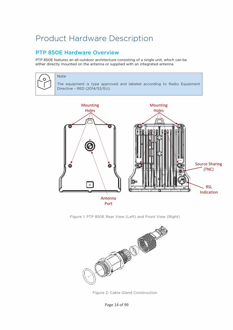
PTP 850E Hardware Overview PTP 850E features an all-outdoor architecture consisting of a single unit, which can be either directly mounted on the antenna or supplied with an integrated antenna.
Note
The equipment is type approved and labeled according to Radio Equipment Directive – RED (2014/53/EU).
Antenna Port
Source Sharing (TNC)
RSL Indication
Mounting Holes
Mounting Holes
Figure 1: PTP 850E Rear View (Left) and Front View (Right)
Figure 2: Cable Gland Construction

Page 15 of 99
PTP 850E Interfaces The PTP 850E has an optical SFP cage, an optical SFP/SFP+ cage, and a QSFP cage for traffic and one RJ-45 port for management and PoE.
For power, the PTP 850E has a DC power interface (-48V) (Port 1). The PTP 850E can also receive PoE power from a Cambium approved PoE injector via Port 2, an RJ-45 port that is also used for management.
Power redundancy can be achieved by using both a DC power input and a passive PoE injector simultaneously. The PTP 850E monitors both power feeds and uses the best power source at any given moment.
DC Power Interface
MGMT1 GE/PoE
(RJ-45)
Multiband Interface
(SFP)
4x1/10GE or 1x40GE
(QSFP)
1GE/10GE(SFP+)
Protection/XPIC
P1 P2 P3 P4 P5 P6
Figure 3: PTP 850E Interfaces – ESE
• Port 1 – Power Interface (-48V) • Port 2 (MNG 1/Eth 1):
o Electric: 10/100/1000Base-T RJ-45. o Management port (no traffic) o PoE
• Port 3 (Eth 2): o SFP cage which supports SFP standard o 1/2.5GE MultiBand port (user-configurable)
• Port 4 (Eth 3, Eth 4, Eth 5, Eth 6): o QSFP cage which supports QSFP standard o 4x1GE/10GE or 1x40GE Eth traffic (user configurable) o Option for SFP+ (1x10GE) with adaptor
• Port 5 (Eth 7): o SFP cage which supports SFP+ standard o 1GE or 10GE Eth traffic (user-configurable)
• Port 6: o External Connection – Used for XPIC and HSB protection.
Page 16 of 99
Note
Not all ports are supported in the initial PTP 850E release. For information on supported ports, check the Release Notes for the Release version you are using.
• Antenna Port –proprietary flange (flange compliant with UG385/U) • RSL interface – DVM interface to enable voltage measurement for RSL indication. The
RSL measurement is performed using standard DVM testing probes. To access the RSL interface, the user must remove the port’s cover and insert the DVM plugs into the sockets, according to the polarization markings.
• Grounding screw
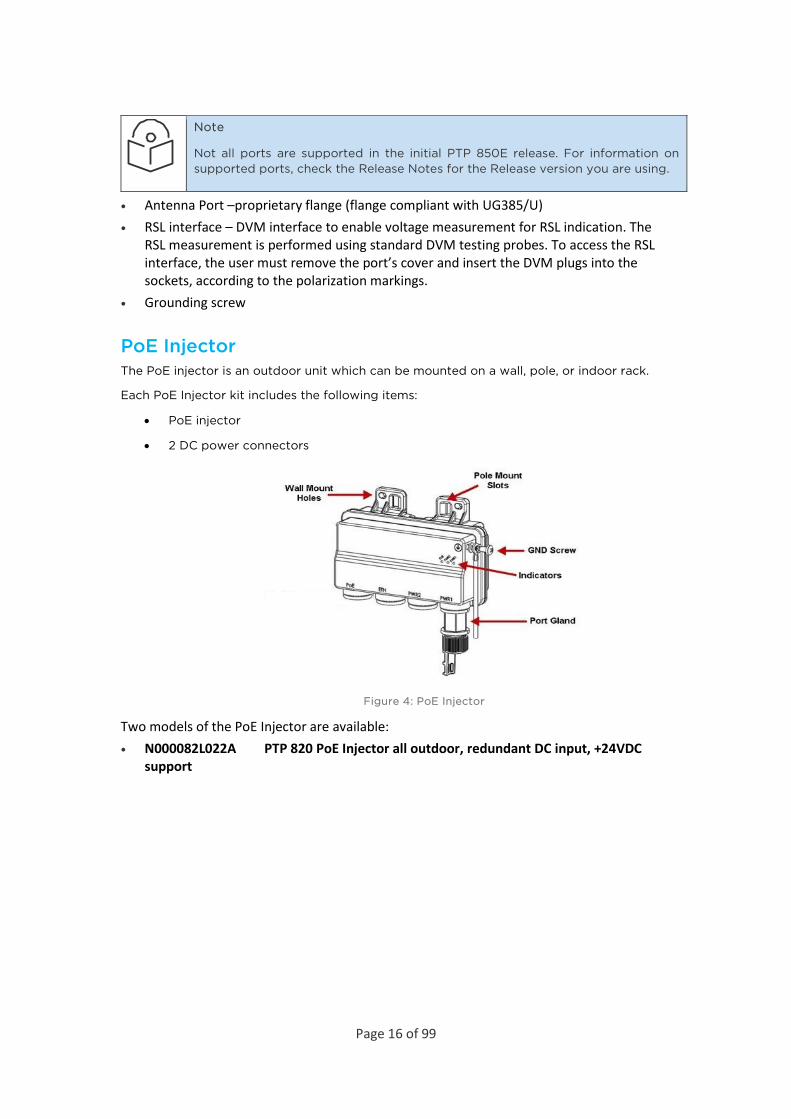
PoE Injector The PoE injector is an outdoor unit which can be mounted on a wall, pole, or indoor rack.
Each PoE Injector kit includes the following items:
• PoE injector
• 2 DC power connectors
Figure 4: PoE Injector
Two models of the PoE Injector are available: • N000082L022A PTP 820 PoE Injector all outdoor, redundant DC input, +24VDC
support

Page 17 of 99
N000082L164A PTP 820C INDOOR AC POE INJECTOR, 90WPoE Injector Interfaces
• Power-Over-Ethernet (PoE) Port
• GbE Data Port supporting 10/100/1000Base-T
• DC Power Port 1 -(18-60) V or -(40-60) V
• DC Power Port 2 -(18-60) V
• Grounding screw
Figure 5: PoE Injector Ports
System Components The following figures show the main components used in the PTP 850E installation procedures.
Figure 6: PTP 850E Figure 7: OMT
Adaptors and Installation Kits
Table 1: PTP 850E Accessories
Part number Description
N800082L001A PTP 820E OMT Kit

Page 18 of 99
N800082L002A PTP 820E Splitter Kit
N800082L003A PTP 820E Coupler Kit
N800082L004A PTP 820E Flat Antenna Mounting kit
Table 2: PoE Injector
Part number Description
N000082L164A PTP 820C INDOOR AC POE INJECTOR, 90W
N000082L022A
PTP 820 PoE Injector all outdoor, redundant DC input, +24VDC support
N000082L020A PTP 820 PoE Injector 19inch rack mount KIT
N000082L021A PTP 820 PoE Injector 23inch rack mount KIT
Antenna Connection Direct Mount:
CommScope (VHLP)
Note
Appropriate lubricant or grease can be applied to the screws that connect the PTP 850E to the antenna interface.
Power Specifications
Power Input Specifications
Standard Input -48 VDC nominal
DC Input range -40.5 to -60 VDC

Page 19 of 99
Power Consumption Specifications
Unit Configuration Maximum Power Consumption
Active 75W
Standby 65W
Power Connection Options
Power Source and Range Data Connection Type
Connection Length
DC Cable Type / Gage
Ext DC -(40.5 ÷ 60)VDC (Using an RJ-45 to DC cable adaptor)
Optical ≤ 75m (247ft) 18AWG
76m ÷ 150m (248ft ÷ 493ft)
14AWG
151m ÷ 300m (494ft ÷ 984ft)
12AWG
Active PoE Injector Electrical ≤ 100m (328ft) CAT5e (24AWG)
Passive PoE Injector for Power Redundancy
Only for use in non-XPIC configurations (≤ 57W)
Electrical ≤ 100m (328ft) CAT5e (24AWG)
PoE Injector Power Input – Standard PoE The specifications in this section are for the standard PoE Injector units with the following marketing models:
N000082L022A PTP 820 PoE Injector all outdoor, redundant DC input, +24VDC supportPoE Injector Power Input – Passive PoE
The specifications in this section are for the passive PoE Injector for use with power redundancy, with the following marketing model: • N000082L164A PTP 820C INDOOR AC POE INJECTOR, 90W
Important Notes! • The unit must only be installed by service personnel. • The unit must have a permanent connection to protective grounding. • SFP and QSFP ports (Port 3, Port 4, and Port 5) do not provide protection from over-
voltages on telecommunication networks for host equipment users. • Disconnect device (circuit breaker) in the building installation: • Shall be readily accessible and incorporated external to the equipment.

Page 20 of 99
• The maximum rating of the overcurrent protection shall be up to 6 Amp.
Environmental Specifications Operating: ETSI EN 300 019-1-4 Class 4.1
Temperature range for continuous operating temperature with high reliability: -33°C (-27°F) to +55°C (131°F)
Temperature range for exceptional temperatures; tested successfully, with limited margins: -45°C (-49°F) to +60°C (140°F)
Humidity: 5%RH to 100%RH IEC529 IP66
Storage : ETSI EN 300 019-1-1 Class 1.2
Transportation : ETSI EN 300 019-1-2 Class 2.3

Page 21 of 99
Cable Installation and Grounding
Minimum and Maximum Cable Diameter To fit the gland, the outer cable diameter should be between 6-10 mm. This applies to all glands on both the PTP 850E unit and the PoE Injector.
Grounding the Cables Cables must be grounded as follows:
• For fiber cables (see Connecting an Optical Fiber Cable and SFP), no grounding is required.
• For DC power cables (see Connecting a DC Power Cable), no grounding is required. • For Ethernet cables, the shielded Ethernet cable (SF/UTP construction) must be
grounded to the antenna tower at the top (next to the RFU), the entry to the indoor cabinet, and every 50m using the kit CAT6a_gnd_kit.
Figure 8: Cable Grounding Kit
Table 3: Cable Grounding Kit
Marketing P/N Description
N000082L017A PTP 820 Grounding Kit for CAT5e F/UTP 8mm cable

Page 22 of 99
To connect the grounding kit:
1. Strip the cable jacket.
2. Place the cable in the middle of the grounding bracket.
3. Close the grounding bracket around the cable.

Page 23 of 99
4. Tighten the two screws to secure the grounding bracket around the cable.
5. Install the grounding lug on the grounding bar.
6. Tighten the grounding lug.
Page 24 of 99
Grounding the PTP 850E Unit
Required Tools
• Metric offset wrench key wrench #3
• Metric wrench 10mm
Procedure
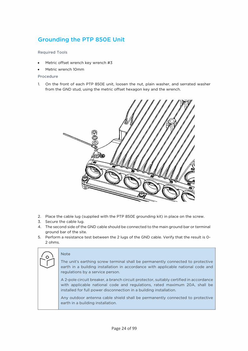
1. On the front of each PTP 850E unit, loosen the nut, plain washer, and serrated washer from the GND stud, using the metric offset hexagon key and the wrench.
2. Place the cable lug (supplied with the PTP 850E grounding kit) in place on the screw. 3. Secure the cable lug. 4. The second side of the GND cable should be connected to the main ground bar or terminal
ground bar of the site. 5. Perform a resistance test between the 2 lugs of the GND cable. Verify that the result is 0-
2 ohms.
Note
The unit’s earthing screw terminal shall be permanently connected to protective earth in a building installation in accordance with applicable national code and regulations by a service person.
A 2-pole circuit breaker, a branch circuit protector, suitably certified in accordance with applicable national code and regulations, rated maximum 20A, shall be installed for full power disconnection in a building installation.
Any outdoor antenna cable shield shall be permanently connected to protective earth in a building installation.
Page 25 of 99
Power Source The power cable must be plugged into the unit before turning on the external power.
When selecting a power source, the following must be considered:
Recommended: Availability of a UPS (Uninterrupted Power Source), battery backup, and emergency power generator.
The power supply must have grounding points on the AC and DC sides.
Caution
The user power supply GND must be connected to the positive pole in the PTP 850E power supply. Any other connection may cause damage to the system!
Note
For the warranty to be honored, you must install the PTP 850E in accordance with the instructions above.
Surge Protection PTP 850E includes built-in surge protection for its Ethernet and power interfaces. PTP 850E’s surge protection implementation complies with surge immunity standard IEC 61000-4-5, level 4, provided the Ethernet cables were prepared according to the instructions in Connecting the Ethernet Cable.
In areas in which severe lighting conditions are likely to occur, it is strongly recommended to add additional protection by placing lightning protectors on all electrical Ethernet cables, near the connection points with the PTP 850E unit.

Page 26 of 99
Available Cable Options
Note
For 10G connections longer than 80m, only Single Mode cables can be used.
Fiber Optic Cables – Single Mode
Part number Item Description
N000082L139A PTP 850 Optical CABLE,SM, 30m
N000082L140A PTP 850 Optical CABLE,SM, 50m
N000082L141A PTP 850 Optical CABLE,SM, 80m
N000082L142A PTP 850 Optical CABLE,SM, 100m
N000082L143A PTP 850 Optical CABLE,SM, 150m
DC Cable and Connector
Marketing P/N Description
N000082L019A
PTP 820 Outdoor_DC_cbl_2x18AWG_drum, 305m
N000082L065A PTP 820 DC Connnector
Ethernet Cable and Specifications
Marketing P/N Description
N000082L016A PTP 850 CAT5E Outdoor 100m drum
This cable has the following specifications:
• Suitable for:
o Fast Ethernet
o Gigabit Ethernet
o PoE
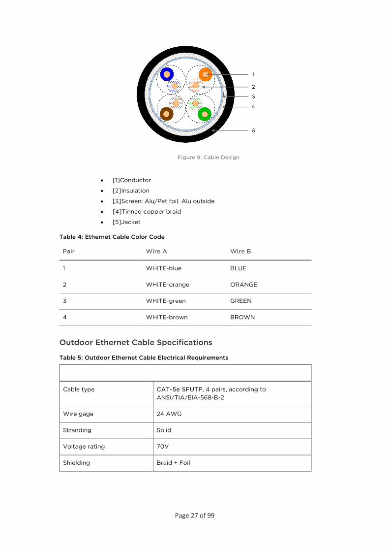
The numbers in the figure below refer to the items listed beneath the figure.
Page 27 of 99
Figure 9: Cable Design
• [1]Conductor
• [2]Insulation
• [3]Screen: Alu/Pet foil. Alu outside
• [4]Tinned copper braid
• [5]Jacket
Table 4: Ethernet Cable Color Code
Pair Wire A Wire B
1 WHITE-blue BLUE
2 WHITE-orange ORANGE
3 WHITE-green GREEN
4 WHITE-brown BROWN
Outdoor Ethernet Cable Specifications
Table 5: Outdoor Ethernet Cable Electrical Requirements
Cable type CAT-5e SFUTP, 4 pairs, according to ANSI/TIA/EIA-568-B-2
Wire gage 24 AWG
Stranding Solid
Voltage rating 70V
Shielding Braid + Foil
Page 28 of 99
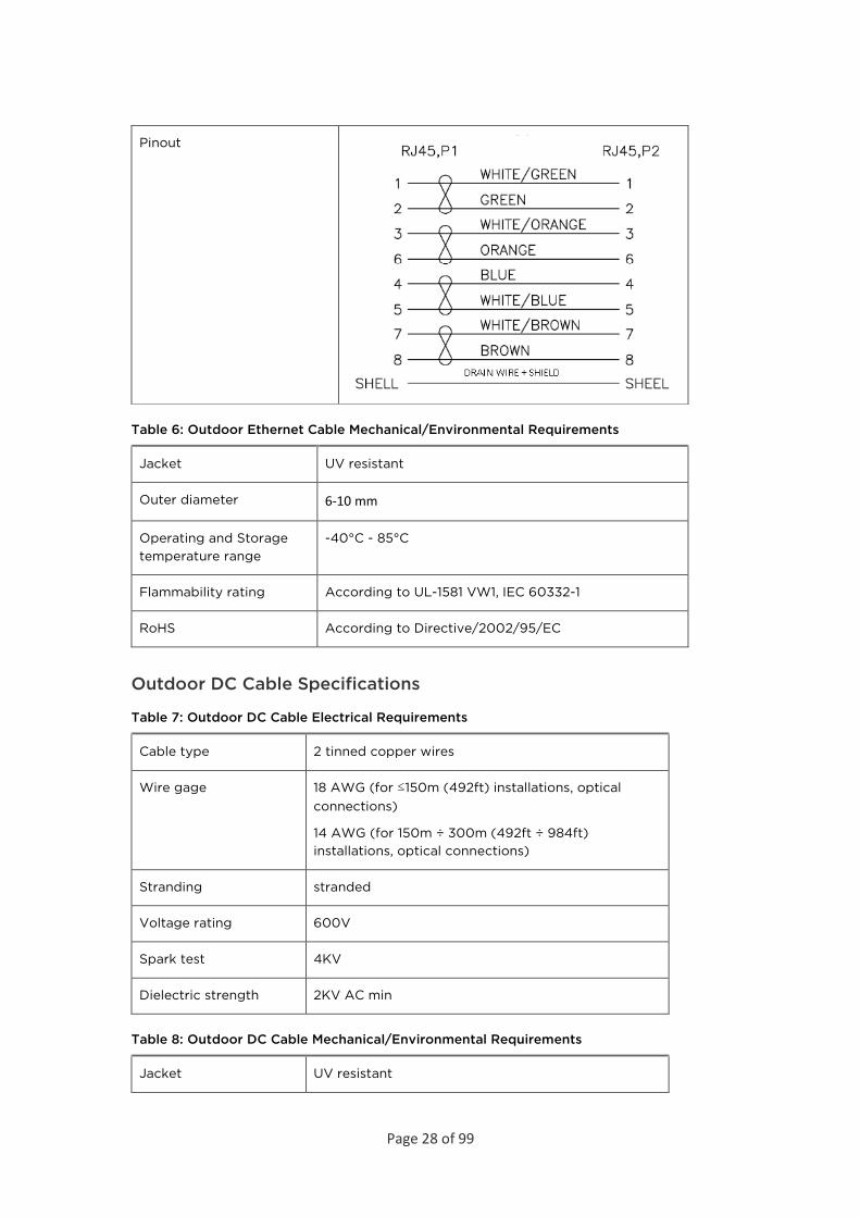
Pinout
Table 6: Outdoor Ethernet Cable Mechanical/Environmental Requirements
Jacket UV resistant
Outer diameter 6-10 mm
Operating and Storage temperature range
-40°C - 85°C
Flammability rating According to UL-1581 VW1, IEC 60332-1
RoHS According to Directive/2002/95/EC
Outdoor DC Cable Specifications
Table 7: Outdoor DC Cable Electrical Requirements
Cable type 2 tinned copper wires
Wire gage 18 AWG (for ≤150m (492ft) installations, optical connections)
14 AWG (for 150m ÷ 300m (492ft ÷ 984ft) installations, optical connections)
Stranding stranded
Voltage rating 600V
Spark test 4KV
Dielectric strength 2KV AC min
Table 8: Outdoor DC Cable Mechanical/Environmental Requirements
Jacket UV resistant
Page 29 of 99
Outer diameter 7-10 mm
Operating & Storage temperature range
-40°C - 85°C
Flammability rating According to UL-1581 VW1, IEC 60332-1
RoHS According to Directive/2002/95/EC
Securing the Cables All cables should be secured at every meter on-site using either a T-Rups kit or cable clamps. When using the T-Rups kit, take special care to apply the proper amount of force in order to avoid damage to the cable. This is especially important for optical (SFP) cables.
Special Instructions for use of Glands
Note
Each PTP 850E unit is supplied with two glands. If additional glands are required, they must be ordered separately, in kits of five glands each.
Table 9: Glands Kit
Part number Marketing Description
N000082L014A PTP 820 Glands_x5_KIT
In addition, gland caps can be ordered to protect the cable and connector from damage when elevating the cable and gland to the radio unit. See Step 5 in Section 3.8.1, General Installation Procedure. Gland caps are ordered separately, in kits of 10 caps each.
Table 10: Gland Cap
Part number Marketing Description
N800082L009A PTP 820E Cable Protection Cap (Qty 10)
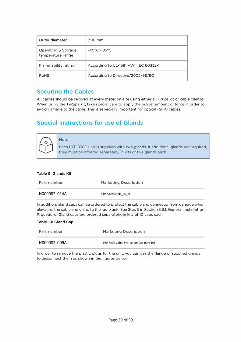
In order to remove the plastic plugs for the unit, you can use the flange of supplied glands to disconnect them as shown in the figures below.
Page 30 of 99
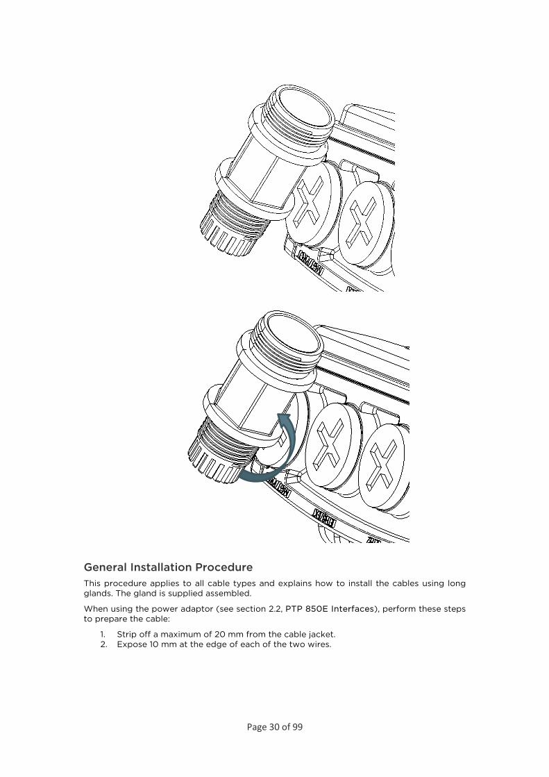
General Installation Procedure This procedure applies to all cable types and explains how to install the cables using long glands. The gland is supplied assembled.
When using the power adaptor (see section 2.2, PTP 850E Interfaces), perform these steps to prepare the cable:
1. Strip off a maximum of 20 mm from the cable jacket. 2. Expose 10 mm at the edge of each of the two wires.
Page 31 of 99
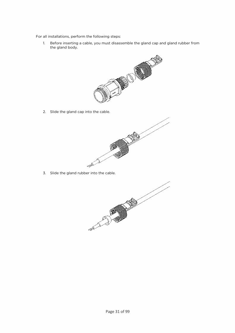
For all installations, perform the following steps:
1. Before inserting a cable, you must disassemble the gland cap and gland rubber from the gland body.
2. Slide the gland cap into the cable.
3. Slide the gland rubber into the cable.

Page 32 of 99
4. Slide the cable into the body of the gland. If you are using a gland cap (see Step 5), make sure to leave enough space for the gland cap to fit into the gland without disturbing the cable.
5. Optionally, after securing the cable into the body of the gland, you can close the other side of the gland with an M28 gland cap. The gland cap protects the cable and connector from damage when elevating the cable and gland to the radio unit.
Page 33 of 99
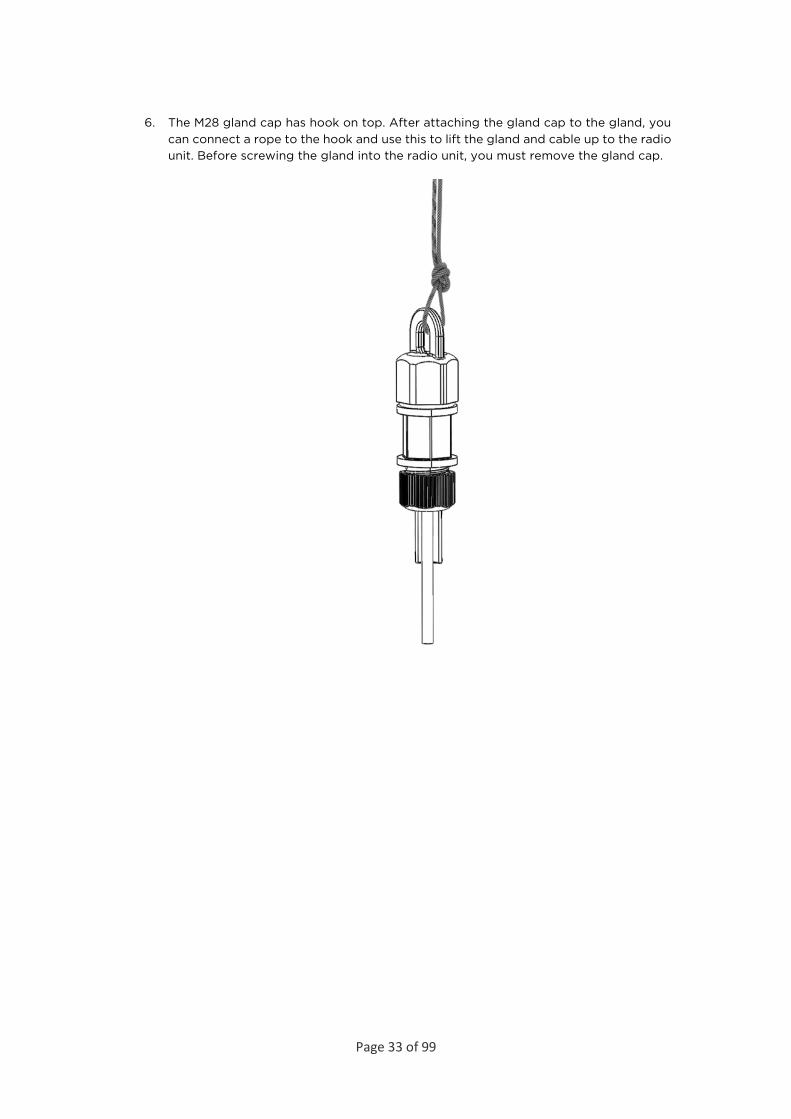
6. The M28 gland cap has hook on top. After attaching the gland cap to the gland, you can connect a rope to the hook and use this to lift the gland and cable up to the radio unit. Before screwing the gland into the radio unit, you must remove the gland cap.
Page 34 of 99
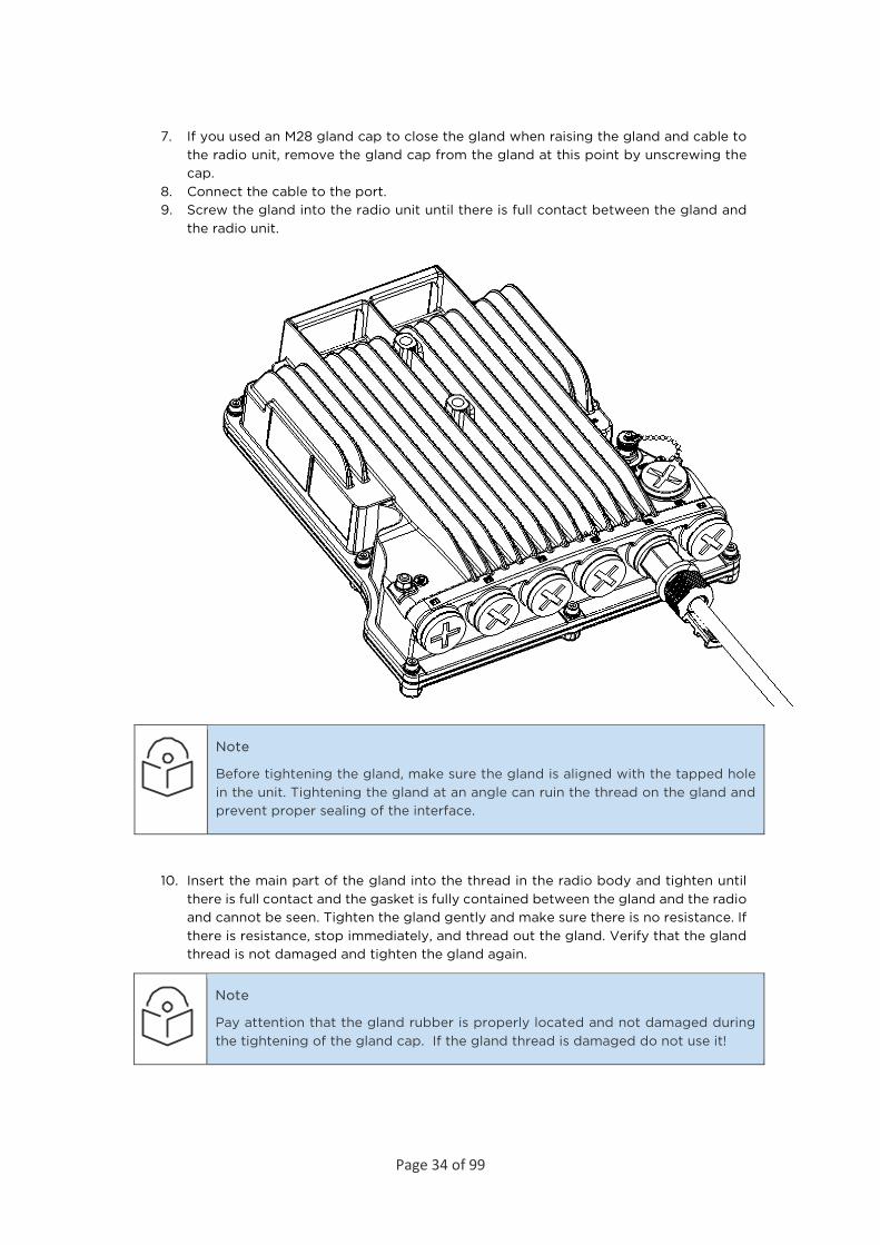
7. If you used an M28 gland cap to close the gland when raising the gland and cable to the radio unit, remove the gland cap from the gland at this point by unscrewing the cap.
8. Connect the cable to the port. 9. Screw the gland into the radio unit until there is full contact between the gland and
the radio unit.
Note
Before tightening the gland, make sure the gland is aligned with the tapped hole in the unit. Tightening the gland at an angle can ruin the thread on the gland and prevent proper sealing of the interface.
10. Insert the main part of the gland into the thread in the radio body and tighten until there is full contact and the gasket is fully contained between the gland and the radio and cannot be seen. Tighten the gland gently and make sure there is no resistance. If there is resistance, stop immediately, and thread out the gland. Verify that the gland thread is not damaged and tighten the gland again.
Note
Pay attention that the gland rubber is properly located and not damaged during the tightening of the gland cap. If the gland thread is damaged do not use it!
Page 35 of 99
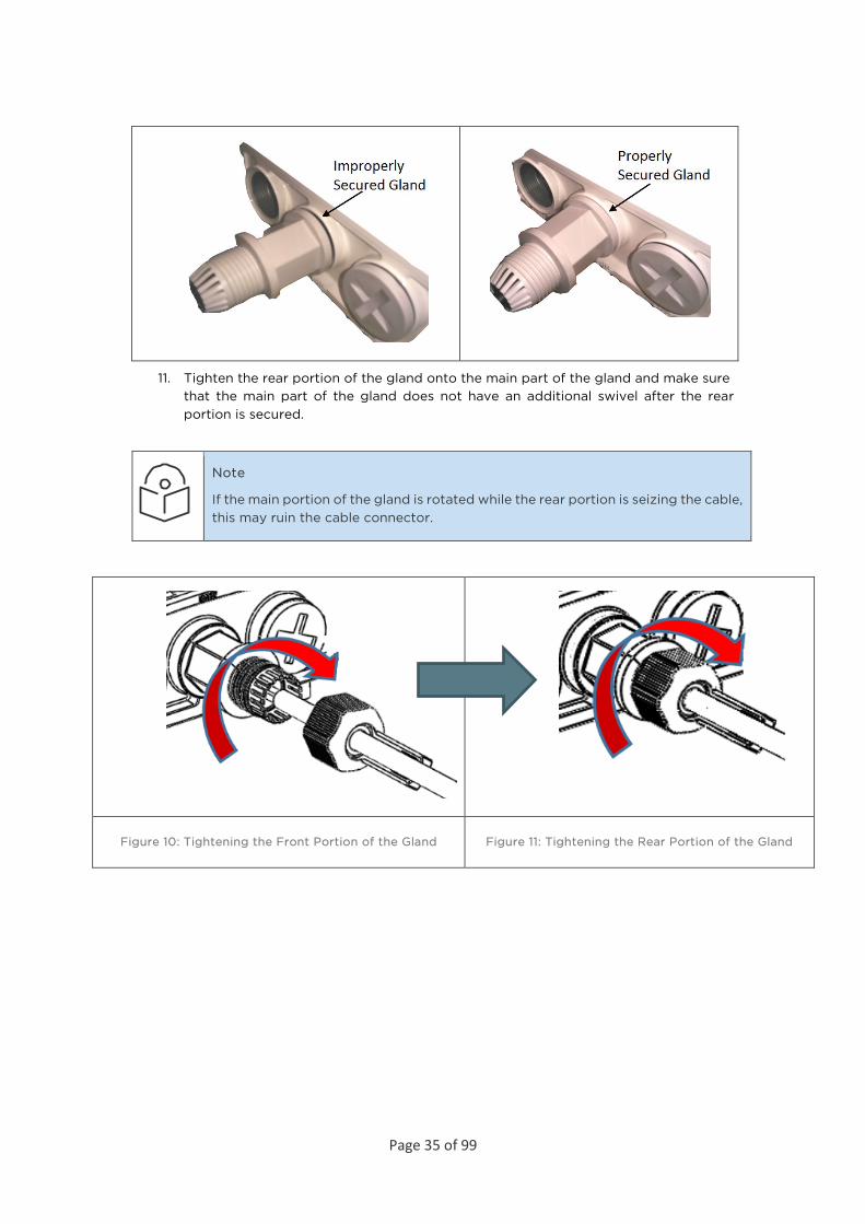
11. Tighten the rear portion of the gland onto the main part of the gland and make sure that the main part of the gland does not have an additional swivel after the rear portion is secured.
Note
If the main portion of the gland is rotated while the rear portion is seizing the cable, this may ruin the cable connector.
Figure 10: Tightening the Front Portion of the Gland Figure 11: Tightening the Rear Portion of the Gland
Page 36 of 99
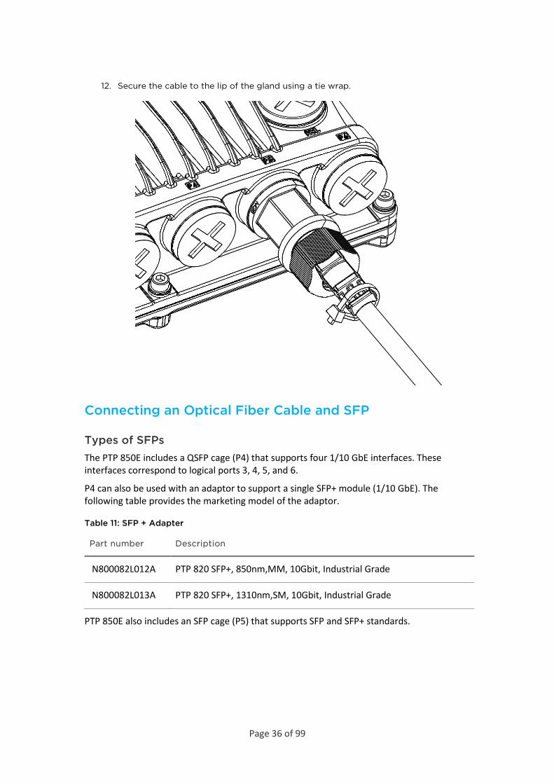
12. Secure the cable to the lip of the gland using a tie wrap.
Connecting an Optical Fiber Cable and SFP
Types of SFPs The PTP 850E includes a QSFP cage (P4) that supports four 1/10 GbE interfaces. These interfaces correspond to logical ports 3, 4, 5, and 6.
P4 can also be used with an adaptor to support a single SFP+ module (1/10 GbE). The following table provides the marketing model of the adaptor.
Table 11: SFP + Adapter
Part number Description
N800082L012A PTP 820 SFP+, 850nm,MM, 10Gbit, Industrial Grade
N800082L013A PTP 820 SFP+, 1310nm,SM, 10Gbit, Industrial Grade
PTP 850E also includes an SFP cage (P5) that supports SFP and SFP+ standards.
Page 37 of 99
The following table lists recommended SFP modules that can be used with PTP 850E.
Table 12: SFP Module Recommendations
Part number Item Description
N000082L059A PTP 820 SFP Optical 1000Base-LX,EXT TEMP
N000082L072A PTP 820 SFP Optical 1000Base-SX,EXT TEMP
N000082L117A PTP 820 SFP Electric Int 1000Base-T,EXT TEMP
The following table lists recommended CSFP modules that can be used with PTP 850E.
Table 13: CSFP Module Recommendations
Part number Item Description
N800082L010A PTP 820 CSFP, 1310nm Tx/1490nm Rx, SM, EXT TEMP
N800082L011A PTP 820 CSFP, 1490nm Tx/1310nm Rx, SM, EXT TEMP
Note
Cambium recommends the use of SFP and SFP+ modules certified by Cambium, as listed above.
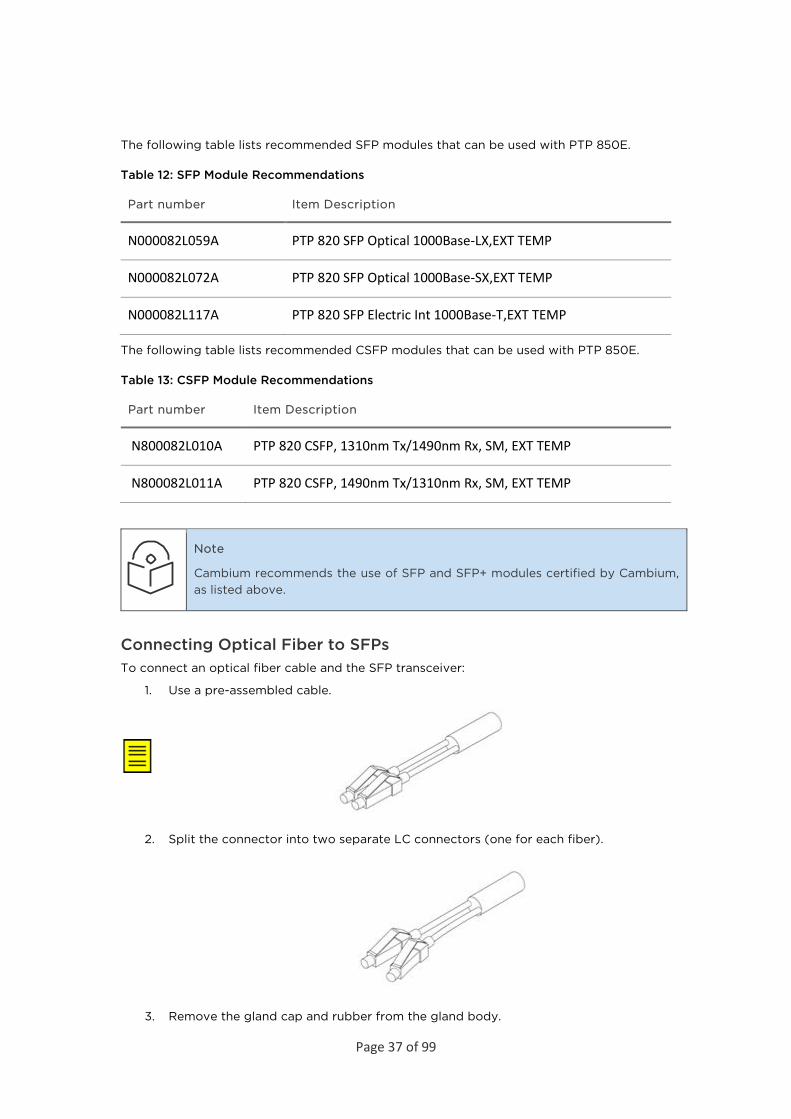
Connecting Optical Fiber to SFPs To connect an optical fiber cable and the SFP transceiver:
1. Use a pre-assembled cable.
2. Split the connector into two separate LC connectors (one for each fiber).
3. Remove the gland cap and rubber from the gland body.
Page 38 of 99
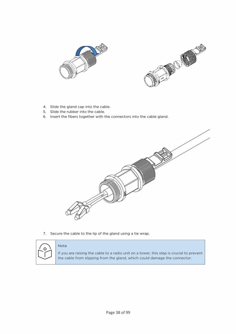
4. Slide the gland cap into the cable. 5. Slide the rubber into the cable. 6. Insert the fibers together with the connectors into the cable gland.
7. Secure the cable to the lip of the gland using a tie wrap.
Note
If you are raising the cable to a radio unit on a tower, this step is crucial to prevent the cable from slipping from the gland, which could damage the connector.

Page 39 of 99
8. Connect the fibers to the SFP transceiver. Listen for the “click” to ensure that they are fully inserted.
9. Remove the tie wrap securing the cable to the gland.
Note
A new tie wrap must be used to secure the cable to the gland at the end of the procedure, as described in Step 13.
10. Connect the connector into the PTP 850E connector.
Page 40 of 99
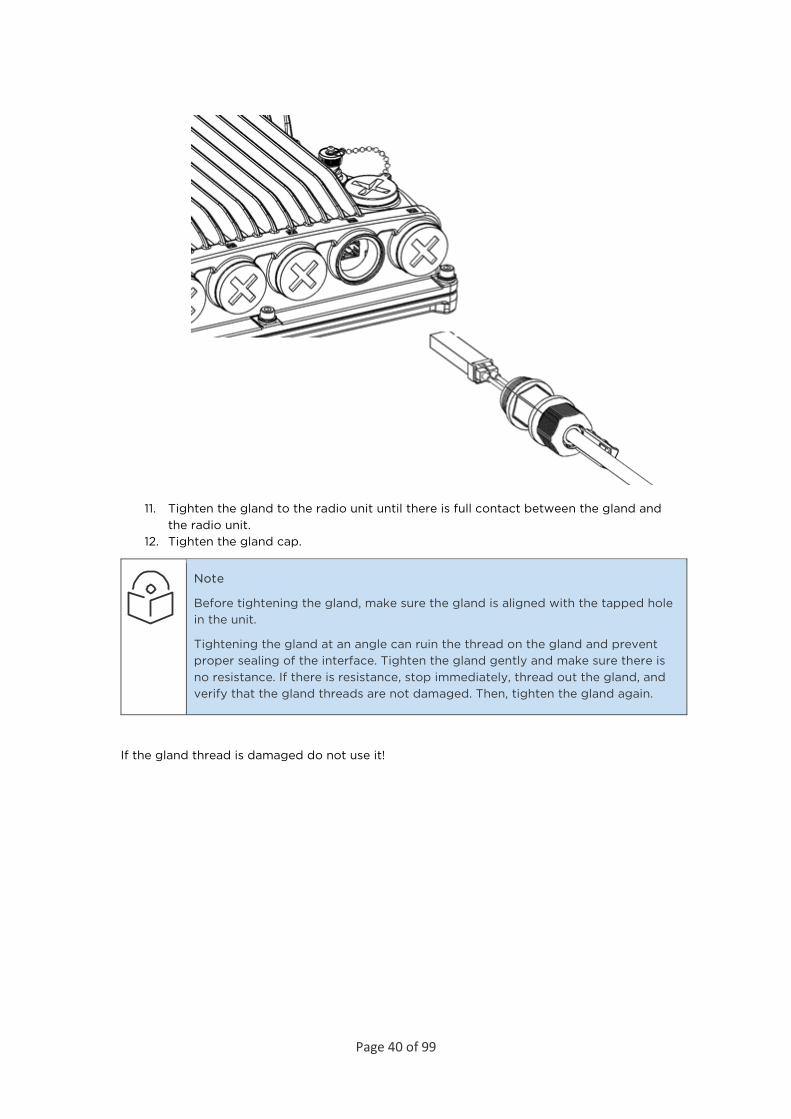
11. Tighten the gland to the radio unit until there is full contact between the gland and the radio unit.
12. Tighten the gland cap.
Note
Before tightening the gland, make sure the gland is aligned with the tapped hole in the unit.
Tightening the gland at an angle can ruin the thread on the gland and prevent proper sealing of the interface. Tighten the gland gently and make sure there is no resistance. If there is resistance, stop immediately, thread out the gland, and verify that the gland threads are not damaged. Then, tighten the gland again.
If the gland thread is damaged do not use it!
Page 41 of 99
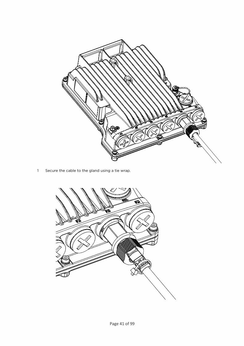
1 Secure the cable to the gland using a tie wrap.
Page 42 of 99
Connecting a DC Power Cable
Note
The DC power cable and connector must be ordered separately. See DC Cable and Connector.
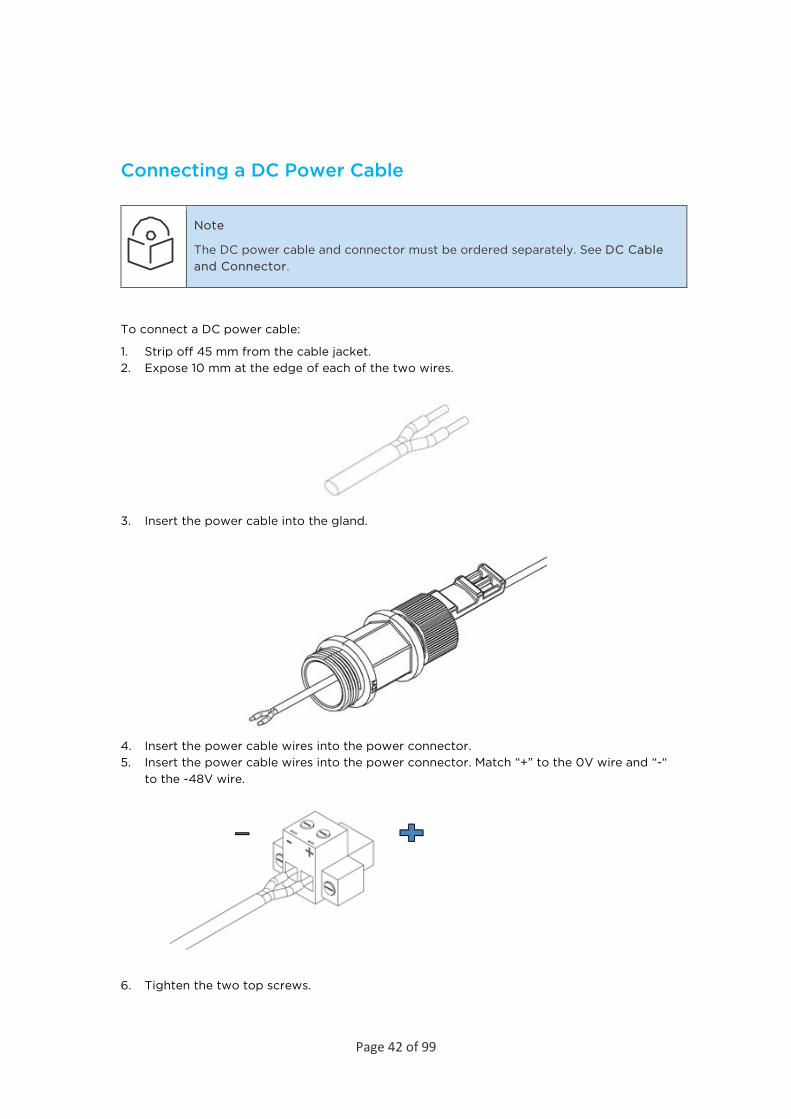
To connect a DC power cable:
1. Strip off 45 mm from the cable jacket. 2. Expose 10 mm at the edge of each of the two wires.
3. Insert the power cable into the gland.
4. Insert the power cable wires into the power connector. 5. Insert the power cable wires into the power connector. Match “+” to the 0V wire and “-“
to the -48V wire.
6. Tighten the two top screws.

Page 43 of 99
7. Plug the power cable with connector into the PTP 850E power connector.
8. Tighten the two front screws.
9. Screw the gland into the radio unit.
Note
Before tightening the gland, make sure the gland is even with the cover. Tighten the gland gently and make sure there is no resistance. If there is resistance, stop immediately and verify that the gland is not being inserted at an angle. Tightening

Page 44 of 99
the gland at an angle can ruin the thread on the gland and prevent proper sealing of the interface.
10. Tighten the gland cap. 11. Secure the cable to the gland with a tie wrap.
Page 45 of 99
Connecting the Ethernet Cable If you need to assemble the Ethernet cable, follow the instructions in Preparing the Ethernet Cable and Plug-in Field, then proceed to Connection of Ethernet Cable to PTP 850E.
If you using a pre-assembled Ethernet cable, follow the instructions in Preparing the Ethernet Cable Already Assembled, then proceed to Connection of Ethernet Cable to PTP 850E.
Note
To ensure proper grounding and connectivity, it is recommended to use pre-assembled Ethernet cables.
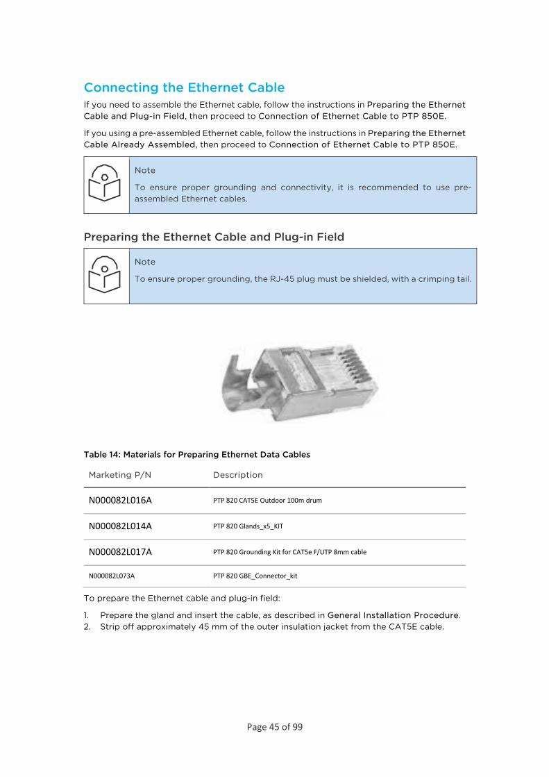
Preparing the Ethernet Cable and Plug-in Field
Note
To ensure proper grounding, the RJ-45 plug must be shielded, with a crimping tail.
Table 14: Materials for Preparing Ethernet Data Cables
Marketing P/N Description
N000082L016A PTP 820 CAT5E Outdoor 100m drum
N000082L014A PTP 820 Glands_x5_KIT
N000082L017A PTP 820 Grounding Kit for CAT5e F/UTP 8mm cable
N000082L073A PTP 820 GBE_Connector_kit
To prepare the Ethernet cable and plug-in field:
1. Prepare the gland and insert the cable, as described in General Installation Procedure. 2. Strip off approximately 45 mm of the outer insulation jacket from the CAT5E cable.

Page 46 of 99
3. Do not strip off the end of the cable shield, but rather, twist the shield to form a braid.
4. Roll back the foil shield insulation and wrap the drain wire around the foil. Do not remove any insulation from the conductors.
5. Align the colored wires.
Note
Cord colors should be matched to the same pins on both ends of the cable.
6. Trim all wires to the same length. About 12 mm on the left should be exposed from the
inner sheath. 7. Separate the wires and place the twisted shield between the separated wires.
8. Insert the wires into the RJ45 plug. Verify that each wire is fully inserted into the front of the RJ45 plug and in the correct order, according to the pinouts shown in Outdoor Ethernet Cable Specifications. The sheath of the Ethernet cable should extend into the plug by about 13 mm and held in place by the crimp.
9. Extend the cable jacket with the shield into the connector about 5 mm for strain relief and shielding connection.
Page 47 of 99
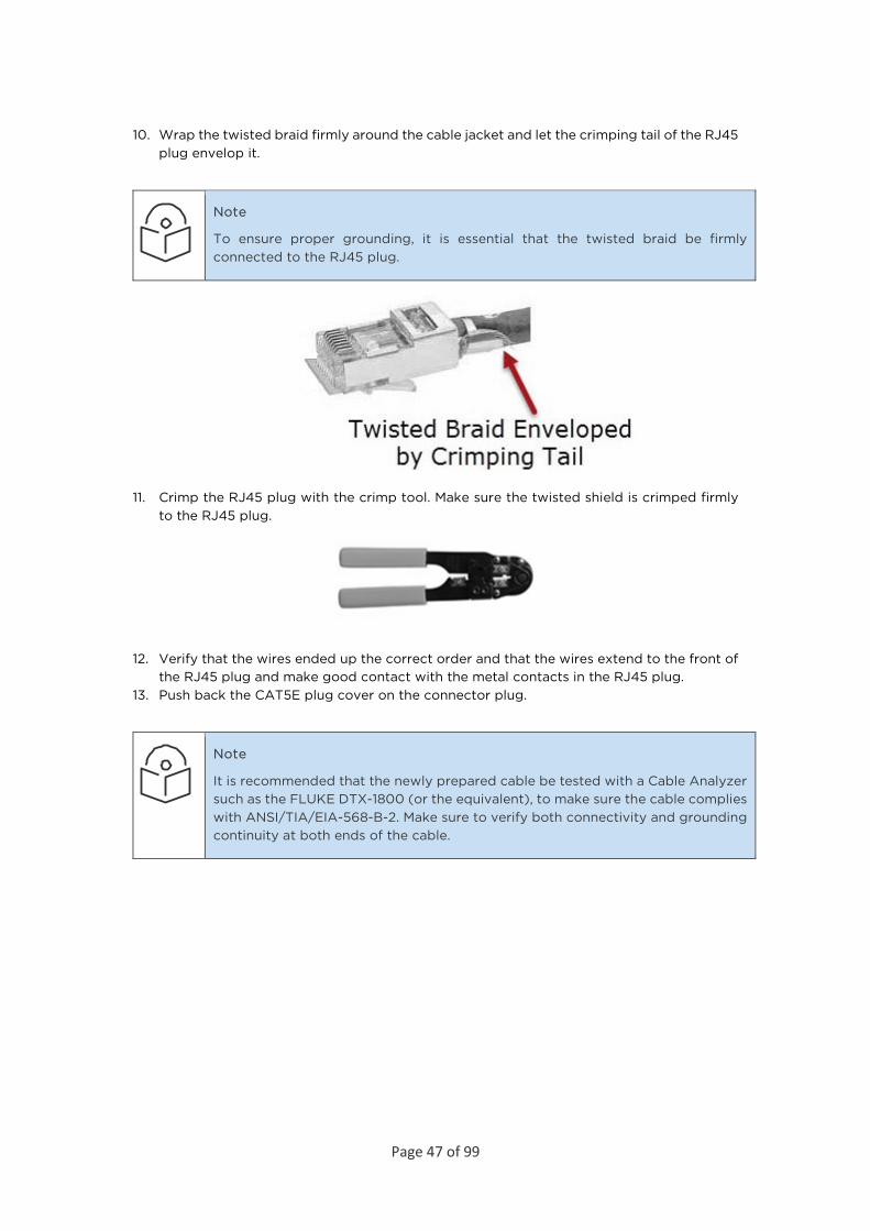
10. Wrap the twisted braid firmly around the cable jacket and let the crimping tail of the RJ45 plug envelop it.
Note
To ensure proper grounding, it is essential that the twisted braid be firmly connected to the RJ45 plug.
11. Crimp the RJ45 plug with the crimp tool. Make sure the twisted shield is crimped firmly to the RJ45 plug.
12. Verify that the wires ended up the correct order and that the wires extend to the front of the RJ45 plug and make good contact with the metal contacts in the RJ45 plug.
13. Push back the CAT5E plug cover on the connector plug.
Note
It is recommended that the newly prepared cable be tested with a Cable Analyzer such as the FLUKE DTX-1800 (or the equivalent), to make sure the cable complies with ANSI/TIA/EIA-568-B-2. Make sure to verify both connectivity and grounding continuity at both ends of the cable.

Page 48 of 99
Preparing the Ethernet Cable Already Assembled To prepare the Ethernet cable already assembled:
1. Release the gland cap and the gland rubber slightly.
2. Insert the CAT5E cable into the gland cap and into the rubber gland.
3. Insert the CAT5e cable into the gland body.
Connection of Ethernet Cable to PTP 850E To connect the Ethernet cable to the PTP 850E:
1. Remove the relevant cap from the PTP 850E radio. You can use the side of the gland to unscrew the cap.
Page 49 of 99
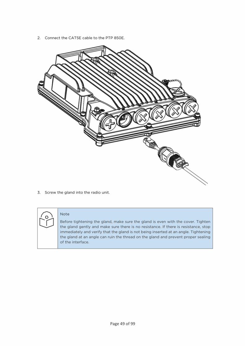
2. Connect the CAT5E cable to the PTP 850E.
3. Screw the gland into the radio unit.
Note
Before tightening the gland, make sure the gland is even with the cover. Tighten the gland gently and make sure there is no resistance. If there is resistance, stop immediately and verify that the gland is not being inserted at an angle. Tightening the gland at an angle can ruin the thread on the gland and prevent proper sealing of the interface.
Page 50 of 99
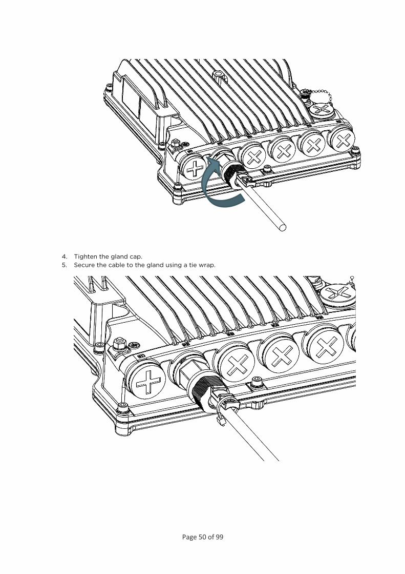
4. Tighten the gland cap. 5. Secure the cable to the gland using a tie wrap.
Page 51 of 99
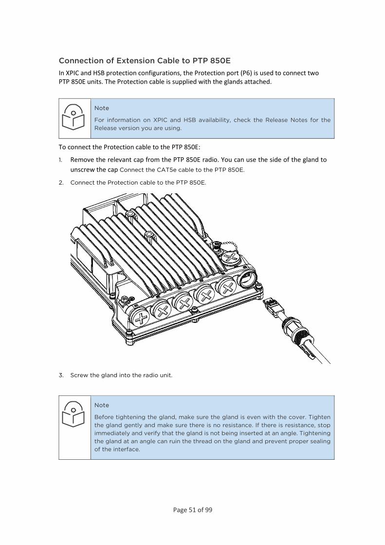
Connection of Extension Cable to PTP 850E In XPIC and HSB protection configurations, the Protection port (P6) is used to connect two PTP 850E units. The Protection cable is supplied with the glands attached.
Note
For information on XPIC and HSB availability, check the Release Notes for the Release version you are using.
To connect the Protection cable to the PTP 850E:
1. Remove the relevant cap from the PTP 850E radio. You can use the side of the gland to unscrew the cap Connect the CAT5e cable to the PTP 850E.
2. Connect the Protection cable to the PTP 850E.
3. Screw the gland into the radio unit.
Note
Before tightening the gland, make sure the gland is even with the cover. Tighten the gland gently and make sure there is no resistance. If there is resistance, stop immediately and verify that the gland is not being inserted at an angle. Tightening the gland at an angle can ruin the thread on the gland and prevent proper sealing of the interface.

Page 52 of 99
4. Tighten the gland cap.
5. Secure the cable to the gland with a tie wrap
6. Connect the other side of the cable to the other PTP 850E following steps 1-5.
Page 53 of 99
PoE Injector Installation and Connection
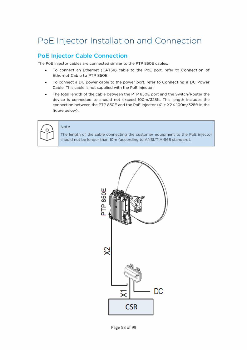
PoE Injector Cable Connection The PoE Injector cables are connected similar to the PTP 850E cables.
• To connect an Ethernet (CAT5e) cable to the PoE port, refer to Connection of Ethernet Cable to PTP 850E.
• To connect a DC power cable to the power port, refer to Connecting a DC Power Cable. This cable is not supplied with the PoE Injector.
• The total length of the cable between the PTP 850E port and the Switch/Router the device is connected to should not exceed 100m/328ft. This length includes the connection between the PTP 850E and the PoE Injector (X1 + X2 ≤ 100m/328ft in the figure below).
Note
The length of the cable connecting the customer equipment to the PoE injector should not be longer than 10m (according to ANSI/TIA-568 standard).
Page 54 of 99
Note
For the warranty to be honored, the connection must be through the glands only. Do not open the PoE injector box cover.
PoE Injector Grounding To ground the PoE Injector:
1. On the right side of each PoE Injector, loosen the screw, plain washer, and serrated washer.
2. Place the cable lug (supplied with the PoE injector kit) between the plain and serrated washer.
3. Tighten the screw. 4. Perform a resistance test between the 2 lugs of the GND cable. Verify that the result is
0-2 ohms.
PoE Injector Wall Mount Installation
List of Items
Item Description Quantity
Remarks
1 PoE Injector 1
1 Glands Kit 1 For outdoor installations.
Note
Glands are required for outdoor installations. The glands kit (three or five glands) is not supplied with the PoE Injector and must be ordered separately.
Glands Kit
Part number Marketing Description
N000082L014A PTP 820 Glands_x5_KIT
Required Tools
• Metric offset wrench key wrench set
• Hammer
• Drilling Machine

Page 55 of 99
Procedure
1. Mount and tighten the PoE Injector to a wall using two M6 bolts and anchors. The M6 bolts and anchors must be purchased separately.
Note
Use Anchor Stainless Steel with flanged Hexagonal nut M6X70.
2. Drill two 6mm diameter holes with 100mm distance between the center of the holes. 3. Insert the anchors with the bolts. 4. Place the washers on the bolt. 5. Tighten the nuts.

Page 56 of 99
PoE Injector Pole Mount Installation
List of Items
Item Description Quantity
Remarks
1 PoE Injector 1
Required Tools
• Slot Screwdriver
Procedure
To mount the PoE Injector on a pole:
1. Mount and tighten the PoE Injector to a pole with a diameter of 114 mm using a stainless-steel hose clamp.
2. Pass the hose clamp through the pole mount slots.

Page 57 of 99
Note
The Hose Clamp is not supplied with PoE injector kit.
3. Attach the PoE injector to the pole. 4. Connect the ends of the hose clamp. 5. Tighten the hose clamp using the captive screw.
PoE Injector 19” Rack Installation
List of Items
Item Description Quantity
Remarks
1 PoE Injector 1
2 PoE Injector 19” Rack Mount Kit
1
Required Tools
• Philips Screwdriver
To mount the PoE Injector on a rack:
1. Mount the PoE Injector to a 19” rack using a 19” rack adaptor. 2. Mount the PoE Injector on the 19” adaptor through the wall mounting holes, using M6
screws and washers.

Page 58 of 99
3. Mount the 19” rack adaptor to a 19” rack using four M6 screws and cage nuts.
PoE Injector ETSI Rack Installation
List of Items
Item Description Quantity
Remarks
1 PoE Injector 1
Page 59 of 99
Item Description Quantity
Remarks
2 PoE Injector ETSI Rack Mount Kit
1
Required Tools
• Philips Screwdriver
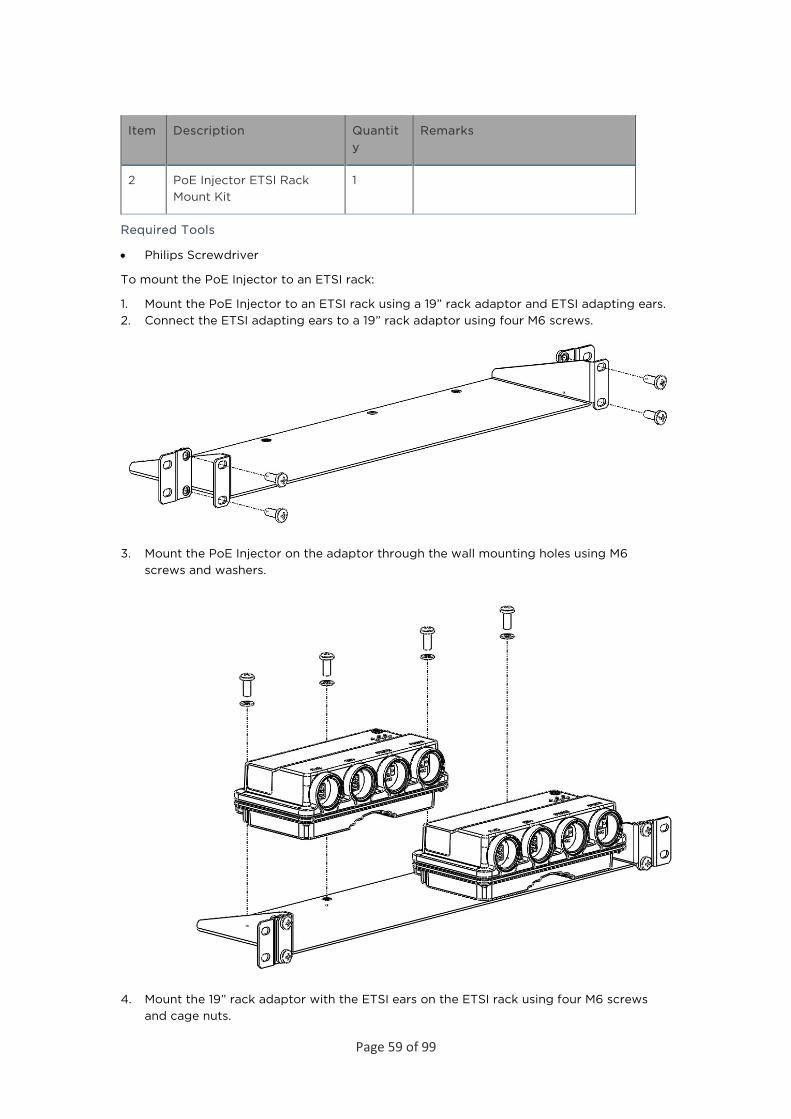
To mount the PoE Injector to an ETSI rack:
1. Mount the PoE Injector to an ETSI rack using a 19” rack adaptor and ETSI adapting ears. 2. Connect the ETSI adapting ears to a 19” rack adaptor using four M6 screws.
3. Mount the PoE Injector on the adaptor through the wall mounting holes using M6 screws and washers.
4. Mount the 19” rack adaptor with the ETSI ears on the ETSI rack using four M6 screws and cage nuts.
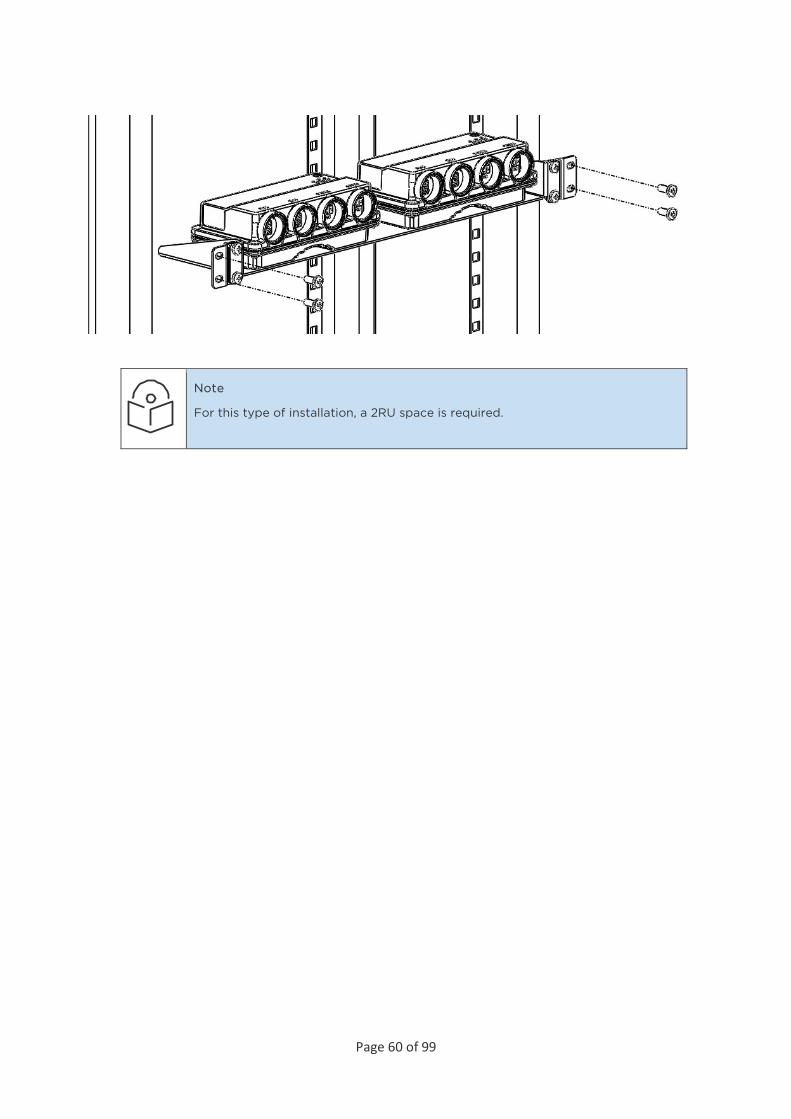
Page 60 of 99
Note
For this type of installation, a 2RU space is required.
Page 61 of 99
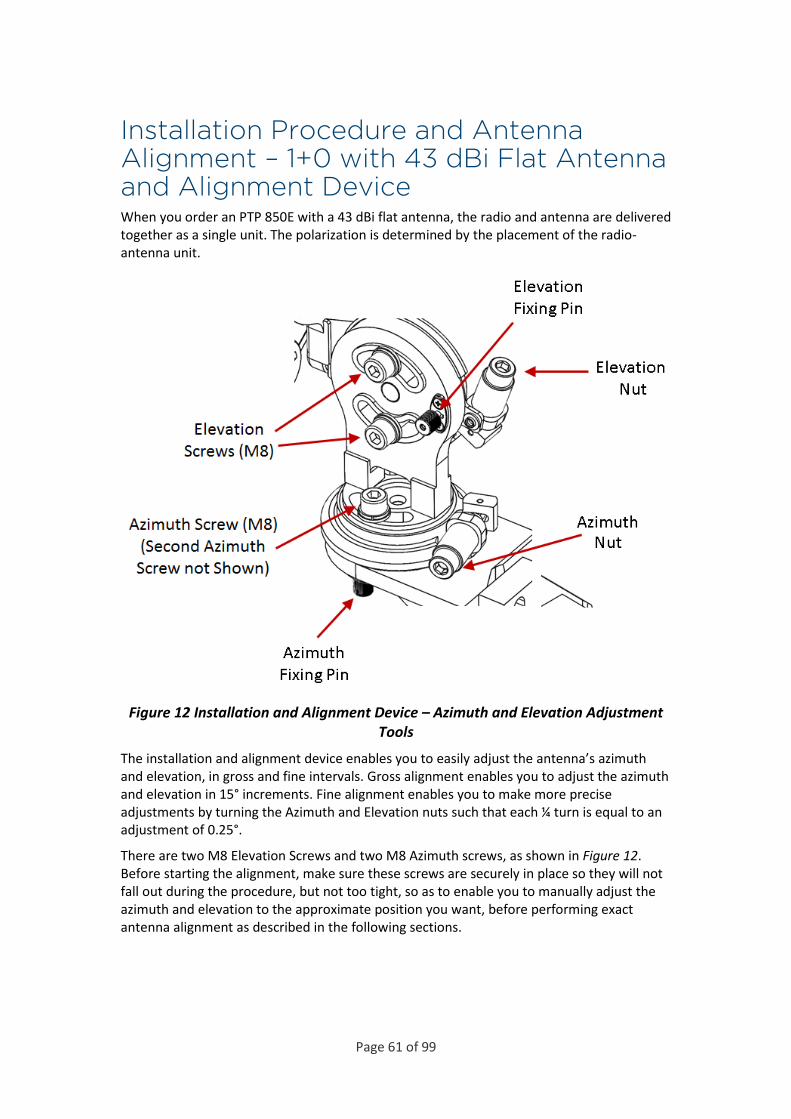
Installation Procedure and Antenna Alignment – 1+0 with 43 dBi Flat Antenna and Alignment Device When you order an PTP 850E with a 43 dBi flat antenna, the radio and antenna are delivered together as a single unit. The polarization is determined by the placement of the radio-antenna unit.
Figure 12 Installation and Alignment Device – Azimuth and Elevation Adjustment Tools
The installation and alignment device enables you to easily adjust the antenna’s azimuth and elevation, in gross and fine intervals. Gross alignment enables you to adjust the azimuth and elevation in 15° increments. Fine alignment enables you to make more precise adjustments by turning the Azimuth and Elevation nuts such that each ¼ turn is equal to an adjustment of 0.25°.
There are two M8 Elevation Screws and two M8 Azimuth screws, as shown in Figure 12. Before starting the alignment, make sure these screws are securely in place so they will not fall out during the procedure, but not too tight, so as to enable you to manually adjust the azimuth and elevation to the approximate position you want, before performing exact antenna alignment as described in the following sections.
Page 62 of 99
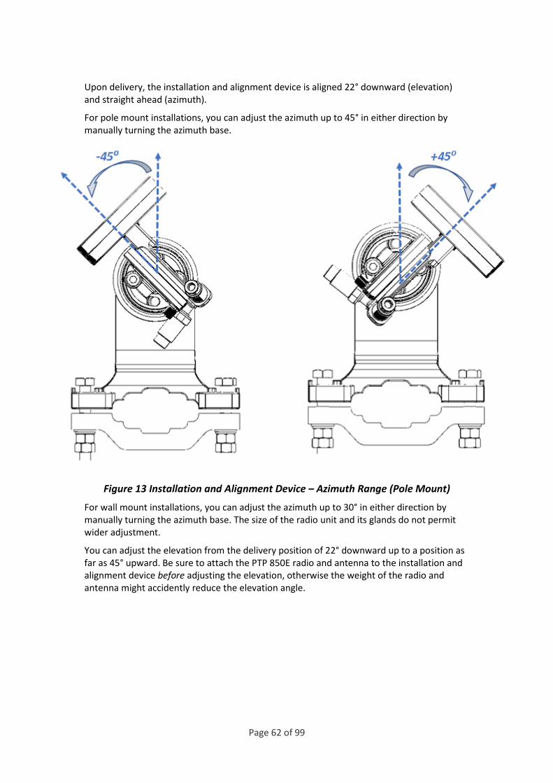
Upon delivery, the installation and alignment device is aligned 22° downward (elevation) and straight ahead (azimuth).
For pole mount installations, you can adjust the azimuth up to 45° in either direction by manually turning the azimuth base.
Figure 13 Installation and Alignment Device – Azimuth Range (Pole Mount)
For wall mount installations, you can adjust the azimuth up to 30° in either direction by manually turning the azimuth base. The size of the radio unit and its glands do not permit wider adjustment.
You can adjust the elevation from the delivery position of 22° downward up to a position as far as 45° upward. Be sure to attach the PTP 850E radio and antenna to the installation and alignment device before adjusting the elevation, otherwise the weight of the radio and antenna might accidently reduce the elevation angle.

Page 63 of 99
Figure 14 Installation and Alignment Device – Delivery Elevation (22° Downward)
You can adjust the elevation upwards as far as 45° upward.
Figure 15 Installation and Alignment Device – Highest Elevation (45° Upward)

Page 64 of 99
Pole Mount Assembly and Installation The pole diameter range for pole mount installations is 8.89 cm – 11.43 cm (3.5 inches – 4.5 inches).
Note
The PTP 850E radio can be assembled on the installation and alignment device on the ground, prior to attaching the device to the pole mount, if the logistics of the location make this more feasible than attaching the radio afterwards. See Attaching the PTP 850E to the Installation and Alignment Device.
List of Items
Item
Description Quantity
Remarks
1 PTP 850E Mounting kit for the PTP 850E 1
2 PTP 850E radio with 43 dBi Flat Antenna 1
Required Tools
• Torque wrench with socket key wrench inch set
• Torque wrench with socket key wrench metric set
• Torque wrench with open metric wrench set
Procedure
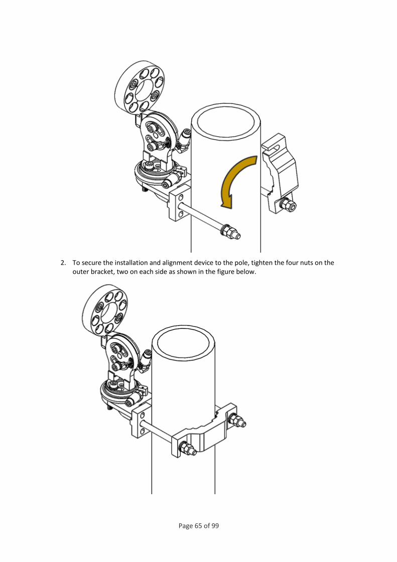
1. Open the outer bracket to slide the installation and alignment device onto the pole, then close the bracket as shown in the figure below.
Page 65 of 99
2. To secure the installation and alignment device to the pole, tighten the four nuts on the outer bracket, two on each side as shown in the figure below.

Page 66 of 99
Wall Mount Assembly and Installation
This section contains instructions for installing a mounting kit on a wall. A mounting kit should only be installed on a concrete wall that is capable of supporting weight of at least 15 kg.
Item Description Quantity Remarks
1 PTP 850E Flat Antenna Mounting Kit 1
2 PTP 850E radio with 43 dBi Flat Antenna
1
3 Anchor screws M8x70 4 Not supplied with mounting kit
4 M8x45 screws 4 Not supplied with mounting kit
5 M8 spring washer 4 Not supplied with mounting kit
6 M8 flat washer 4 Not supplied with mounting kit
Required Tools
• Appropriate key wrench for the M8x45 screws • A drilling machine
Note
In wall mount assembly, the 4 M10 nuts, 2 M10 flat and spring washers, 2 M10x150 screws, and the rear bracket that are supplied with the mounting kit are not used.

Page 67 of 99
Procedure 1. Place the mounting kit on the wall and mark four screws positions.
2. Remove the bracket and drill four holes into the wall.
3. Insert the anchor screws into the wall.
4. Place the mounting kit in front of the 4 anchor screws and tighten the 4 M8 screws, spring washers, and flat washers to secure the mounting device to the wall.
Page 68 of 99
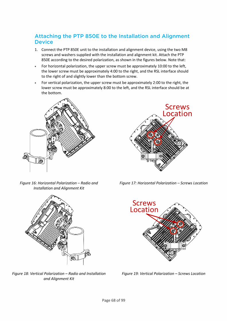
Attaching the PTP 850E to the Installation and Alignment Device 1. Connect the PTP 850E unit to the installation and alignment device, using the two M8
screws and washers supplied with the installation and alignment kit. Attach the PTP 850E according to the desired polarization, as shown in the figures below. Note that:
• For horizontal polarization, the upper screw must be approximately 10:00 to the left, the lower screw must be approximately 4:00 to the right, and the RSL interface should to the right of and slightly lower than the bottom screw.
• For vertical polarization, the upper screw must be approximately 2:00 to the right, the lower screw must be approximately 8:00 to the left, and the RSL interface should be at the bottom.
Screws Location
Figure 16: Horizontal Polarization – Radio and Installation and Alignment Kit
Figure 17: Horizontal Polarization – Screws Location
Screws Location
Figure 18: Vertical Polarization – Radio and Installation and Alignment Kit
Figure 19: Vertical Polarization – Screws Location

Page 69 of 99
Performing Antenna Alignment Using the Enhanced Alignment Kit You can easily adjust the azimuth and elevation of the antenna using a number of screws and nuts located on the installation and alignment device (Figure 28).
Adjusting the Antenna Azimuth
Note
For wall-mount installations, if it is necessary to adjust the azimuth by more than 45°, you must first adjust the position of the Azimuth Screws. See Extending the Azimuth Range.
Performing Gross Azimuth Adjustment To adjust the antenna azimuth:
1. Loosen the Azimuth Fixing Pin (Figure 28) by pulling it gently out of its groove and rotating it counter-clockwise.
Page 70 of 99
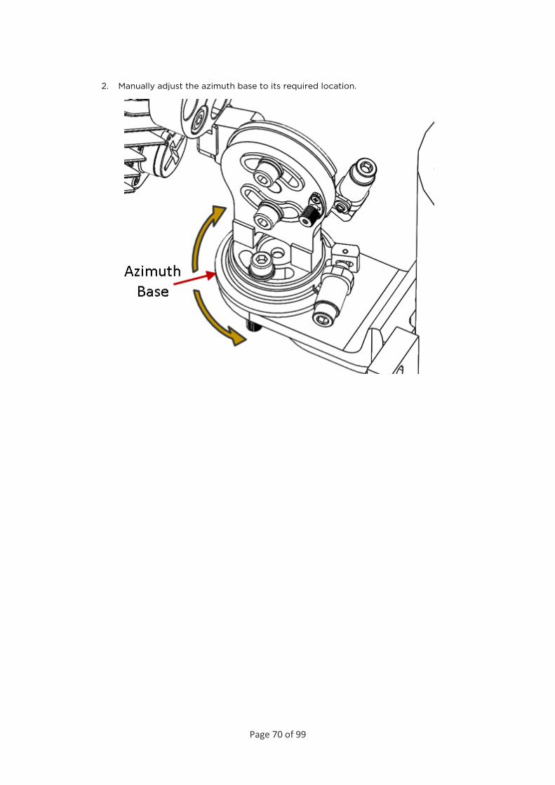
2. Manually adjust the azimuth base to its required location.

Page 71 of 99
3. Once the azimuth base has been adjusted to its approximate location, lock the azimuth fixing pin by rotating the pin clockwise until it appears to be aligned with its groove. At this point, you must adjust the azimuth base until the fixing pin slips into its groove. There are notches within the device that enable you to adjust the azimuth in 15° increments. You can then perform fine azimuth adjustment as described below. You will hear a click when the pin slips into the groove.

Page 72 of 99
Performing Fine Azimuth Adjustment To perform fine azimuth alignment:
1. Turn the Azimuth Nut (Figure 28), either by hand or using a key wrench, for fine tuning of the azimuth. Each ¼ turn is equal to an adjustment of 0.25°.
2. Tighten the two M8 Azimuth Screws connected to the azimuth base.
Adjusting the Antenna Elevation
Performing Gross Elevation Adjustment To perform gross adjustment of the antenna elevation:
1. Loosen the Elevation Fixing Pin (Figure 28) by pulling it gently out of its groove and rotating it counter-clockwise.
Page 73 of 99
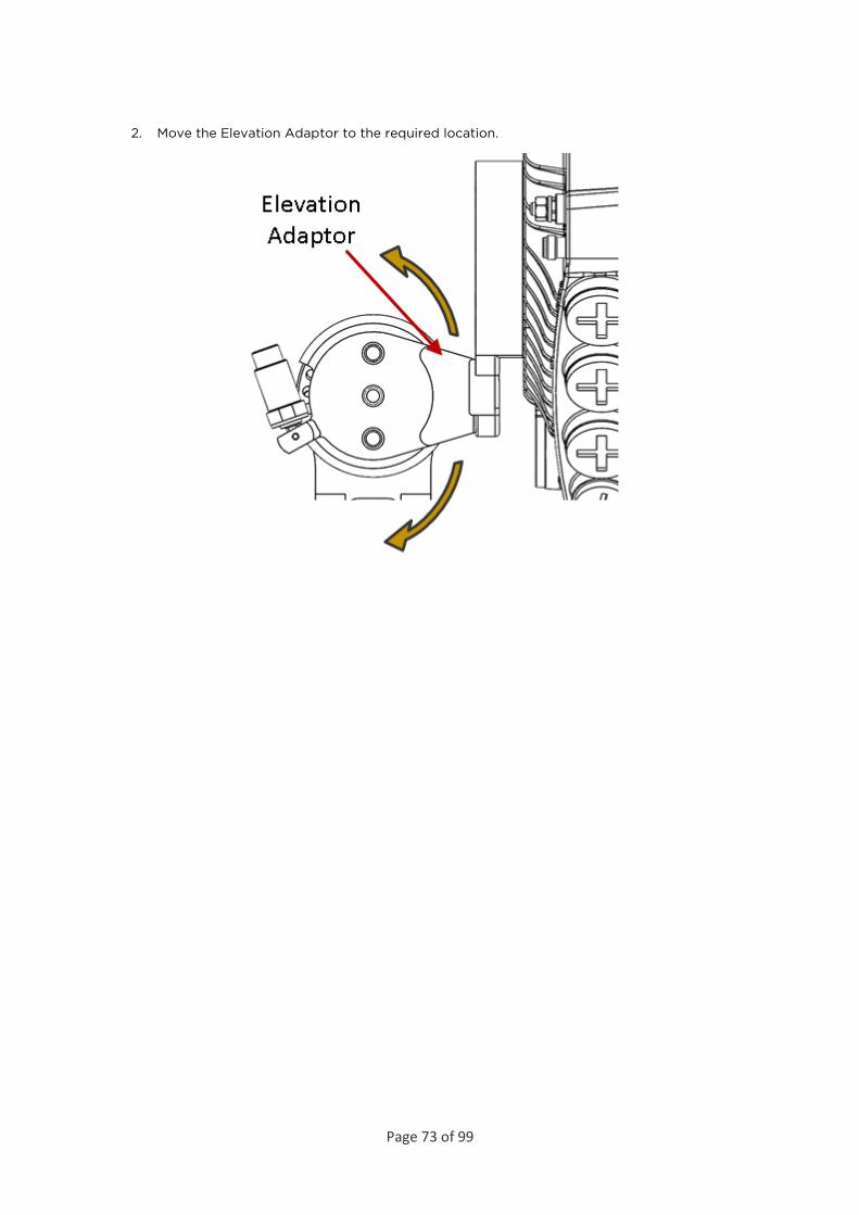
2. Move the Elevation Adaptor to the required location.

Page 74 of 99
3. Once the Elevation Adaptor has been adjusted to its approximate location, lock the elevation fixing pin by rotating the pin clockwise until it appears to be aligned with its groove. At this point, you must adjust the Elevation Adaptor until the fixing pin slips into its groove. There are notches within the device that enable you to adjust the elevation in 15° increments. You can then perform fine elevation adjustment as described below. You will hear a click when the pin slips into the groove.

Page 75 of 99
Performing Fine Elevation Adjustment To perform fine elevation alignment:
1. Turn the Elevation Nut (Figure 28), either by hand or using a key wrench, for fine tuning of the elevation. Each ¼ turn is equal to an adjustment of 0.25°.
2. Tighten the two M8 Elevation Screws connected to the Elevation Adaptor.

Page 76 of 99
Direct Mount Configurations
1+0 Direct Mount Installation
List of Items
Item
Description Quantity Remarks
1 PTP 850E RADIO 1
Required Tools
The following tools are required for the PTP 850E installation:
• Metric offset hexagon key wrench #6
• Phillips #2 screwdriver
Procedure
To install the PTP 850E in a direct mount 1+0 configuration:
Note
Do not remove the transparent pressure window located on the antenna interface.
Antenna Interface

Page 77 of 99
Note
If necessary, change the antenna polarization by rotating the unit in accordance with the relevant antenna installation guide.
Twist orientation:
• For horizontal polarization, locate the twist with the letter “H” vertical to the hook cover (at 3:00) and fasten the two screws.
Page 78 of 99
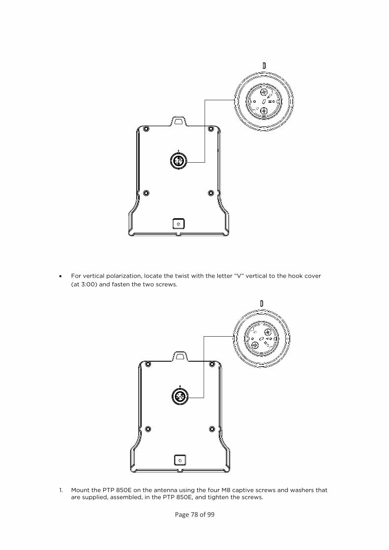
• For vertical polarization, locate the twist with the letter “V” vertical to the hook cover (at 3:00) and fasten the two screws.
1. Mount the PTP 850E on the antenna using the four M8 captive screws and washers that are supplied, assembled, in the PTP 850E, and tighten the screws.
Page 79 of 99
Note
Make sure the polarization mounting direction of the PTP 850E is correct.
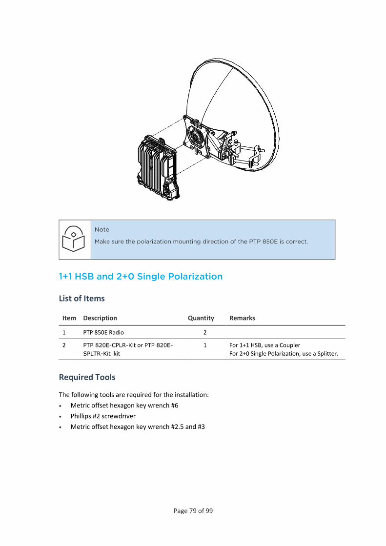
1+1 HSB and 2+0 Single Polarization
List of Items
Item Description Quantity Remarks
1 PTP 850E Radio 2
2 PTP 820E-CPLR-Kit or PTP 820E-SPLTR-Kit kit
1 For 1+1 HSB, use a Coupler For 2+0 Single Polarization, use a Splitter.
Required Tools
The following tools are required for the installation: • Metric offset hexagon key wrench #6 • Phillips #2 screwdriver • Metric offset hexagon key wrench #2.5 and #3

Page 80 of 99
Procedure
To install an PTP 850E in a direct mount 1+1 or 2+0 SP configuration:
1 If necessary, change the polarization of the coupler or splitter to the desired polarization by loosening the twist, changing the polarization as indicated below, and re-tightening the screws. Use 0.8 Nm torque for the #4-40 screws on the twist.
Twist
Coupler/Splitter
Important: Make sure the polarization mounting direction of the twist to the coupler or splitter is according to the antenna polarization.
Figure 20: Horizontal Polarization

Page 81 of 99
Figure 21: Vertical Polarization
2 Mount the coupler or splitter on the antenna using the four M8 screws and washers supplied with the coupler or splitter kit, and tighten the screws.
3 Mount the two O-Rings supplied with the coupler or splitter kit, as shown in the following figure.
Page 82 of 99
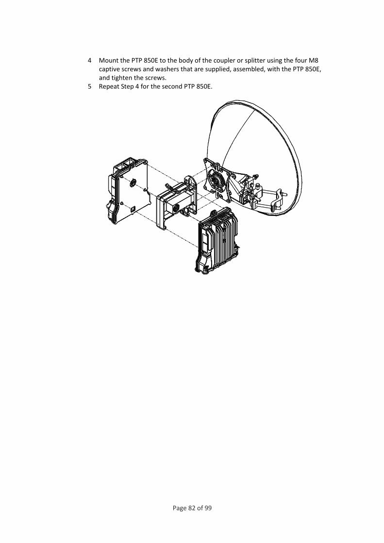
4 Mount the PTP 850E to the body of the coupler or splitter using the four M8 captive screws and washers that are supplied, assembled, with the PTP 850E, and tighten the screws.
5 Repeat Step 4 for the second PTP 850E.
Page 83 of 99
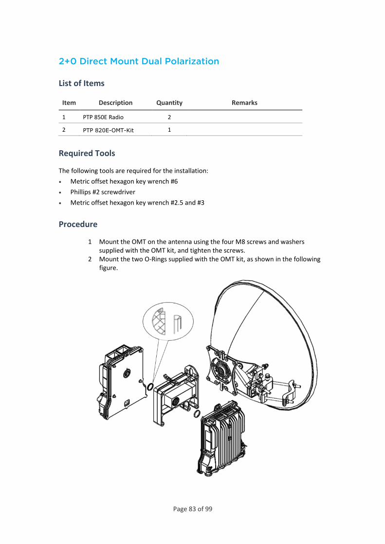
2+0 Direct Mount Dual Polarization
List of Items
Item Description Quantity Remarks
1 PTP 850E Radio 2
2 PTP 820E-OMT-Kit 1
Required Tools
The following tools are required for the installation: • Metric offset hexagon key wrench #6 • Phillips #2 screwdriver • Metric offset hexagon key wrench #2.5 and #3
Procedure
1 Mount the OMT on the antenna using the four M8 screws and washers supplied with the OMT kit, and tighten the screws.
2 Mount the two O-Rings supplied with the OMT kit, as shown in the following figure.
Page 84 of 99
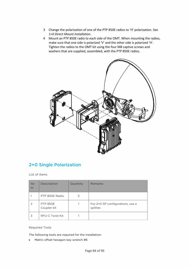
3 Change the polarization of one of the PTP 850E radios to ‘H’ polarization. See 1+0 Direct Mount Installation.
4 Mount an PTP 850E radio to each side of the OMT. When mounting the radios, make sure that one side is polarized ‘V’ and the other side is polarized ‘H’. Tighten the radios to the OMT kit using the four M8 captive screws and washers that are supplied, assembled, with the PTP 850E radios.
2+0 Single Polarization
List of Items
Item
Description Quantity Remarks
1 PTP 850E Radio 2
2 PTP 850E Coupler kit
1 For 2+0 SP configurations, use a splitter.
3 RFU-C Twist Kit 1
Required Tools
The following tools are required for the installation:
• Metric offset hexagon key wrench #6
Page 85 of 99
• Phillips #2 screwdriver
• Metric offset hexagon key wrench #2.5 and #3
Procedure
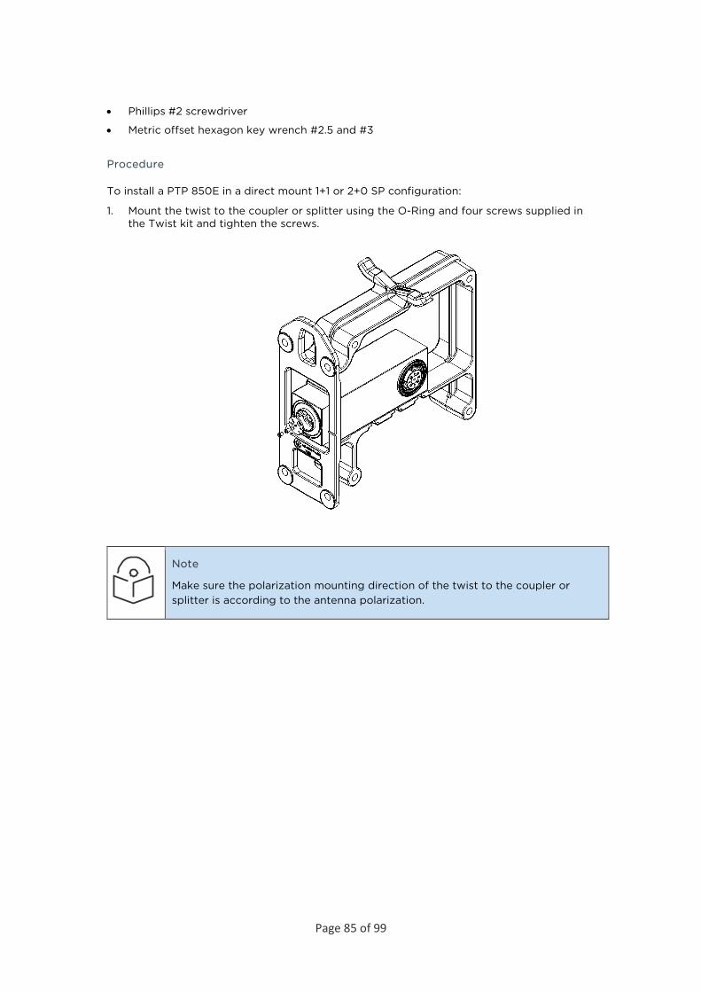
To install a PTP 850E in a direct mount 1+1 or 2+0 SP configuration:
1. Mount the twist to the coupler or splitter using the O-Ring and four screws supplied in the Twist kit and tighten the screws.
Note
Make sure the polarization mounting direction of the twist to the coupler or splitter is according to the antenna polarization.
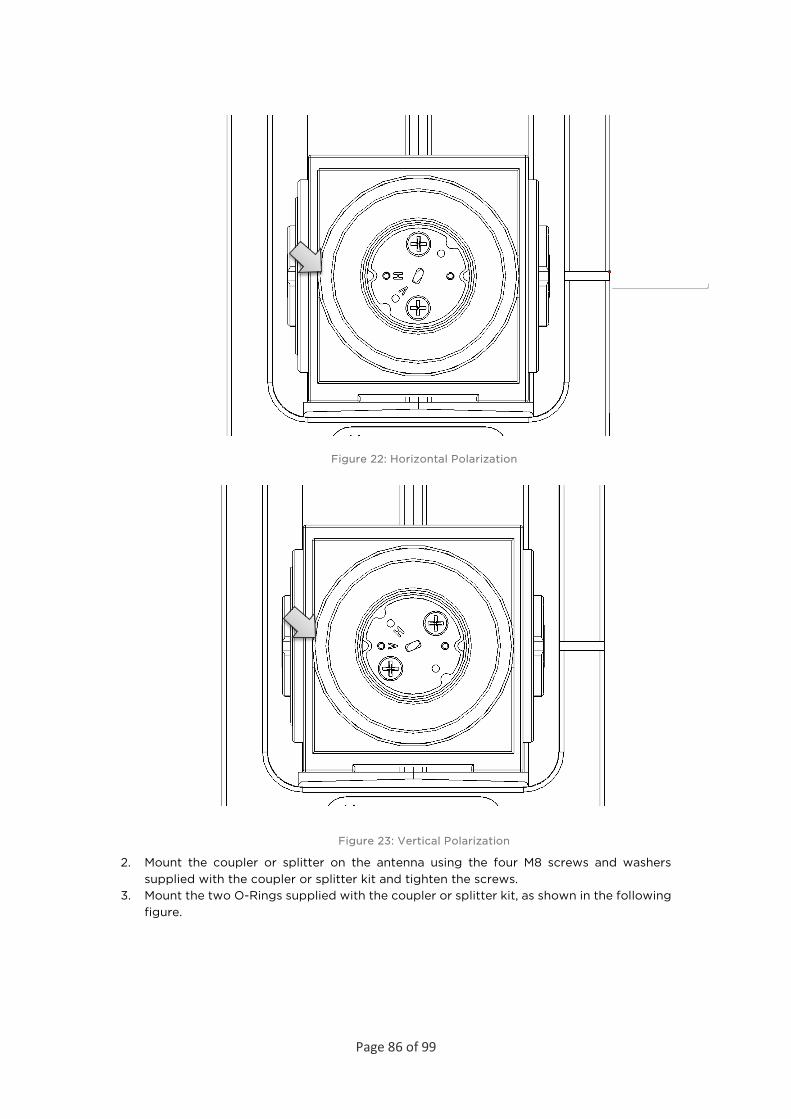
Page 86 of 99
Figure 22: Horizontal Polarization
Figure 23: Vertical Polarization
2. Mount the coupler or splitter on the antenna using the four M8 screws and washers supplied with the coupler or splitter kit and tighten the screws.
3. Mount the two O-Rings supplied with the coupler or splitter kit, as shown in the following figure.

Page 87 of 99
4. Mount the PTP 850E to the body of the coupler or splitter using the four M8 captive screws and washers that are supplied, assembled, with the PTP 850E, and tighten the screws.
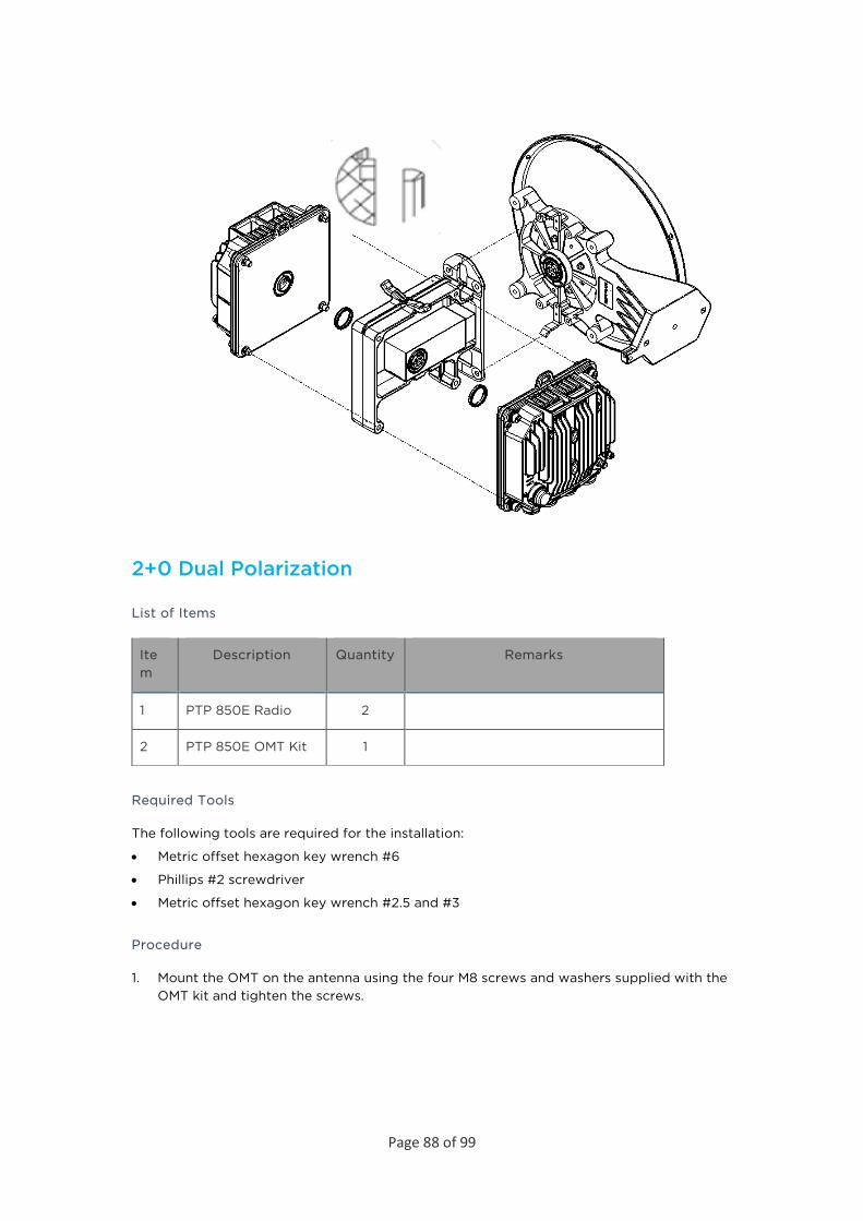
Page 88 of 99
2+0 Dual Polarization
List of Items
Item
Description Quantity Remarks
1 PTP 850E Radio 2
2 PTP 850E OMT Kit 1
Required Tools
The following tools are required for the installation:
• Metric offset hexagon key wrench #6
• Phillips #2 screwdriver
• Metric offset hexagon key wrench #2.5 and #3
Procedure
1. Mount the OMT on the antenna using the four M8 screws and washers supplied with the OMT kit and tighten the screws.
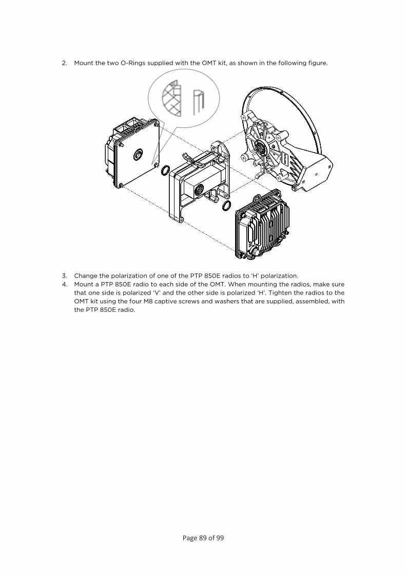
Page 89 of 99
2. Mount the two O-Rings supplied with the OMT kit, as shown in the following figure.
3. Change the polarization of one of the PTP 850E radios to ‘H’ polarization. 4. Mount a PTP 850E radio to each side of the OMT. When mounting the radios, make sure
that one side is polarized ‘V’ and the other side is polarized ‘H’. Tighten the radios to the OMT kit using the four M8 captive screws and washers that are supplied, assembled, with the PTP 850E radio.
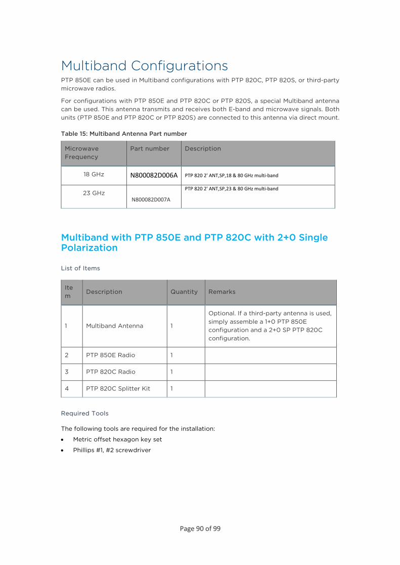
Page 90 of 99
Multiband Configurations PTP 850E can be used in Multiband configurations with PTP 820C, PTP 820S, or third-party microwave radios.
For configurations with PTP 850E and PTP 820C or PTP 820S, a special Multiband antenna can be used. This antenna transmits and receives both E-band and microwave signals. Both units (PTP 850E and PTP 820C or PTP 820S) are connected to this antenna via direct mount.
Table 15: Multiband Antenna Part number
Microwave Frequency
Part number Description
18 GHz N800082D006A PTP 820 2' ANT,SP,18 & 80 GHz multi-band
23 GHz N800082D007A
PTP 820 2' ANT,SP,23 & 80 GHz multi-band
Multiband with PTP 850E and PTP 820C with 2+0 Single Polarization
List of Items
Item
Description Quantity Remarks
1 Multiband Antenna 1
Optional. If a third-party antenna is used, simply assemble a 1+0 PTP 850E configuration and a 2+0 SP PTP 820C configuration.
2 PTP 850E Radio 1
3 PTP 820C Radio 1
4 PTP 820C Splitter Kit 1
Required Tools
The following tools are required for the installation:
• Metric offset hexagon key set
• Phillips #1, #2 screwdriver
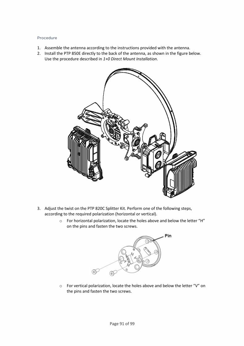
Page 91 of 99
Procedure
1. Assemble the antenna according to the instructions provided with the antenna. 2. Install the PTP 850E directly to the back of the antenna, as shown in the figure below.
Use the procedure described in 1+0 Direct Mount Installation.
3. Adjust the twist on the PTP 820C Splitter Kit. Perform one of the following steps, according to the required polarization (horizontal or vertical).
o For horizontal polarization, locate the holes above and below the letter “H” on the pins and fasten the two screws.
o For vertical polarization, locate the holes above and below the letter “V” on the pins and fasten the two screws.

Page 92 of 99
4. Mount and tighten the PTP 820C Splitter Kit at a 90° angle to the antenna using the four M8 screws and washers.
5. Mount and tighten the PTP 820C to the PTP 820C Splitter Kit using the four M8 captive screws and washers supplied with the PTP 820C radio.

Page 93 of 99
Multiband with PTP 850E and PTP 820C with 2+0 Dual Polarization
List of Items
Item
Description Quantity
Remarks
1 Multiband Antenna 1 Optional. If a third-party antenna is used, simply assemble a 1+0 PTP 850E configuration and a 2+0 DP PTP 820C configuration.
2 PTP 850E Radio 1
3 PTP 820C Radio 1
4 PTP 820C OMT Kit 1
5 CIRC./CIRC. ADAPTOR
1 Per Antenna Vendor
Required Tools
The following tools are required for the installation:
• Metric offset hexagon key set
• Metric wrench key set
• Phillips #2 screwdriver
Procedure
1. Prior to the installation, follow the antenna manufacturer’s instructions to use the circular adaptor. Remove the existing rectangular transition, swap the O-ring, and install the circular transition instead.
2. Assemble the antenna according to the instructions provided with the antenna. 3. Install the PTP 850E directly to the back of the antenna, as shown in the figure below. Use
the procedure described in 1+0 Direct Mount Installation.

Page 94 of 99
4. Connect the OMT at a 90° angle to the antenna and secure it with the four screws supplied with the OMT kit. Verify the existence of the O-ring.
5. Connect the PTP 820C unit to the OMT using the four M8 captive screws and washers supplied with the PTP 820C and tighten the screws.

Page 95 of 99
Multiband with PTP 850E and 1+0 PTP 820S
List of Items
Item
Description Quantity Remarks
1 Multiband Antenna 1 Optional. If a third-party antenna is used, simply assemble a 1+0 PTP 850E configuration and a 1+0 PTP 820S configuration.
2 PTP 850E Radio 1
3 PTP 820S Radio 1
Required Tools
The following tools are required for the installation:
• Metric offset hexagon key wrench #6
• Metric wrench key set • Phillips #2 screwdriver
Procedure
1. Prior to the installation, follow the antenna manufacturer’s instructions to use the circular adaptor. Remove the existing rectangular transition, swap the O-ring, and install the circular transition instead.
2. Assemble the antenna according to the instructions provided with the antenna. 3. Install the PTP 850E directly to the back of the antenna, as shown in the figure below.
Use the procedure described in 1+0 Direct Mount Installation.

Page 96 of 99
4. Mount the PTP 820S on the antenna using the four M8 captive screws and washers that are supplied, assembled, with the PTP 820S, and tighten the screws.
Note
Make sure the polarization mounting direction of the PTP 820S is correct.
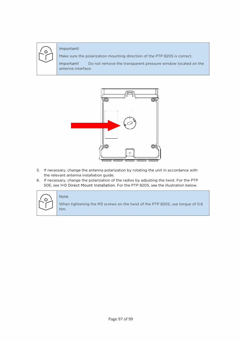
Page 97 of 99
Important!
Make sure the polarization mounting direction of the PTP 820S is correct.
Important! Do not remove the transparent pressure window located on the antenna interface.
5. If necessary, change the antenna polarization by rotating the unit in accordance with the relevant antenna installation guide.
6. If necessary, change the polarization of the radios by adjusting the twist. For the PTP 50E, see 1+0 Direct Mount Installation. For the PTP 820S, see the illustration below.
Note
When tightening the M3 screws on the twist of the PTP 820S, use torque of 0.6 Nm.

Page 98 of 99
Figure 24: PTP 820STwist Orientation
• For horizontal polarization, locate the twist with the letter “H” vertical to the hook cover and fasten the two screws.

Page 99 of 99
• For vertical polarization, locate the twist with the letter “V” vertical to the hook cover and fasten the two screws.