Embed Size (px)
Citation preview
Version 4.2 (May 14, 2019)
User Manual
PTC10 Programmable Temperature Controller

PTC10 Programmable Temperature Controller
Certification Stanford Research Systems certifies that this product met its published specifications at the time of shipment. Warranty This Stanford Research Systems product is warranted against defects in materials and workmanship for a period of one (1) year from the date of shipment. Service For warranty service or repair, this product must be returned to a Stanford Research Systems authorized service facility. Contact Stanford Research Systems or an authorized representative before returning this product for repair. Information in this document is subject to change without notice. Copyright © Stanford Research Systems, Inc., 2019. All rights reserved. Stanford Research Systems, Inc. 1290-C Reamwood Avenue Sunnyvale, California 94089 Phone: (408) 744-9040 Fax: (408) 744-9049 www.thinkSRS.com Printed in the USA

Contents i
PTC10 Programmable Temperature Controller
Contents
Safety and preparation for use....................................................................................... v Specifications .................................................................................................................. vii
Introduction 1 I/O cards ............................................................................................................................ 2
PTC320 thermistor/diode/RTD card .................................................................................... 2 PTC321 RTD reader ................................................................................................................ 5 PTC323 2-channel thermistor/diode/RTD card ................................................................... 6 PTC330 thermocouple reader .............................................................................................. 11 PTC420 AC output card........................................................................................................ 13 PTC430 50 W DC output card ............................................................................................. 14 PTC431 100W DC output card ............................................................................................ 15 PTC440 TEC driver ............................................................................................................... 17 PTC510 analog I/O card ....................................................................................................... 20 PTC520 digital I/O card ........................................................................................................ 20
Operation 23 Quick start tutorial ........................................................................................................ 24
Turn the instrument on .......................................................................................................... 24 The Select screen ................................................................................................................... 24 Configure the sensor inputs ................................................................................................... 24 If the sensor reading does not appear ................................................................................... 25 Plot data .................................................................................................................................. 25 Test the outputs ..................................................................................................................... 26 Set the data logging rate ......................................................................................................... 27 Save data to and retrieve data from a USB memory device ................................................ 27 Interface with a computer ...................................................................................................... 28 Control a temperature........................................................................................................... 29
Acquiring and logging data ........................................................................................... 36 Input filters .............................................................................................................................. 36 Custom calibration tables ...................................................................................................... 36 Virtual channels ...................................................................................................................... 38 Logging data to internal memory ........................................................................................... 39 Logging data to USB ............................................................................................................... 39 ADC sampling and logged data ............................................................................................. 39 Format of PTC10 log files ...................................................................................................... 40
Using the system fan ..................................................................................................... 41 Using PID feedback ........................................................................................................ 42
How stable is the PTC10’s feedback control? ...................................................................... 42 Basic PID feedback concepts ................................................................................................. 42 Manual tuning .......................................................................................................................... 43 Automatic tuning algorithms .................................................................................................. 46 Using the automatic tuner...................................................................................................... 49
Front-panel controls ...................................................................................................... 52

Contents ii
PTC10 Programmable Temperature Controller
USB logging indicator ............................................................................................................. 52 “Help” key .............................................................................................................................. 52 “Output Enable” key .............................................................................................................. 52 “Select” screen ....................................................................................................................... 53 “Numeric” screen .................................................................................................................. 54 “Plot” screen........................................................................................................................... 54 “Program” screen ................................................................................................................... 59 “Channel” screen ................................................................................................................... 64 “System” screen ..................................................................................................................... 78
Firmware updates .......................................................................................................... 85 Replacing the clock battery .......................................................................................... 86
Remote programming 87 Connecting to the PTC10 ...................................................................................................... 87 Communication, assembly, and run-time errors .................................................................. 90 Concurrent macros ................................................................................................................ 90 Macro names .......................................................................................................................... 91 Command syntax ................................................................................................................... 91
Remote instructions ...................................................................................................... 95 General instructions ............................................................................................................... 95 IEEE 488.2 Instructions ........................................................................................................... 99 Program submenu ................................................................................................................ 103 System submenu ................................................................................................................... 106 <channel> submenu ............................................................................................................ 110 Error codes ........................................................................................................................... 121 Startup macro ....................................................................................................................... 122
Sample macros ............................................................................................................. 123 Temperature profiles ........................................................................................................... 123 Control a feedback setpoint with an analog input .............................................................. 124 PID input scheduling ............................................................................................................. 124 Show channels with tripped alarms on the Numeric screen ............................................. 125 Make a virtual channel show the PID setpoint .................................................................... 125 Linearizing outputs when interfacing with external power supplies .................................. 125 Control instrument functions with the digital IO lines ....................................................... 126 Drive a solid state relay with the digital IO lines ................................................................. 127
PC applications 129 PTCFileConverter ....................................................................................................... 130 FileGrapher ................................................................................................................... 132
File menu ............................................................................................................................... 132 Edit menu .............................................................................................................................. 132 Process menu ....................................................................................................................... 134 Special menu ......................................................................................................................... 136 Command line and macro instructions ............................................................................... 137
Circuit description 141 Core system cards ....................................................................................................... 142
PTC212 CPU board ............................................................................................................. 142 PTC221 backplane ............................................................................................................... 142

Contents iii
PTC10 Programmable Temperature Controller
PTC231 front panel .............................................................................................................. 144 PTC240 GPIB card ............................................................................................................... 145
I/O cards ........................................................................................................................ 146 PTC320 1-channel thermistor/diode/RTD reader ........................................................... 146 PTC321 4-channel RTD reader ........................................................................................... 147 PTC330 thermocouple reader ............................................................................................ 148 PTC420 AC output card...................................................................................................... 149 PTC430 50W DC output card ............................................................................................ 149 PTC431 100W DC output card .......................................................................................... 150 PTC440 TEC driver ............................................................................................................. 151 PTC510 analog I/O card ..................................................................................................... 152 PTC520 digital I/O card ...................................................................................................... 153
Parts List 155 PTC212 CPU board ............................................................................................................. 155 PTC221 backplane ............................................................................................................... 165 PTC231 front panel .............................................................................................................. 167 PTC240 GPIB option ........................................................................................................... 169 PTC320 1-channel thermistor, diode, and RTD reader .................................................... 170 PTC321 4-channel RTD reader ........................................................................................... 173 PTC330 thermocouple reader ............................................................................................ 176 PTC420 AC output card...................................................................................................... 180 PTC430 50W DC output card ............................................................................................ 182 PTC440 TEC driver ............................................................................................................. 184 PTC510 analog I/O card ..................................................................................................... 187 PTC520 digital I/O card ...................................................................................................... 189
Schematics 193


Safety and Preparation for Use v
PTC10 Programmable Temperature Controller
Safety and preparation for use
Line voltage
The PTC10 operates from an 88 to 264 VAC power source having a line frequency between 47 and 63 Hz.
Power entry module
A power entry module, labeled AC POWER on the back panel of the PTC10, provides connection to the power source and to a protective ground.
Power cord
The PTC10 package includes a detachable, three-wire power cord for connection to the power source and protective ground.
The exposed metal parts of the box are connected to the power ground to protect against electrical shock. Always use an outlet which has a properly connected protective ground. Consult with an electrician if necessary.
Grounding
A chassis grounding lug is available on the back panel of the PTC10. Connect a heavy duty ground wire, #12AWG or larger, from the chassis ground lug directly to a facility earth ground to provide additional protection against electrical shock.
Line fuse
Use a 10 A/250 V 3AB Slo-Blo fuse.
Operate only with covers in place
To avoid personal injury, do not remove the product covers or panels. Do not operate the product without all covers and panels in place.
Serviceable parts
The PTC10 does not include any user serviceable parts inside. Refer service to a qualified technician.


Specifications vii
PTC10 Programmable Temperature Controller
Specifications
PTC10 temperature controller
Maximum PID rate 50 or 60 Hz, depending on AC line frequency Data logging rate 10 samples/second/channel – 1 sample/hour/channel (can be set
independently for each channel or globally for all channels) Display resolution 0.001 °C, °F, K, V, A, W, etc. if –1000 < displayed value < 1000; 6 significant figures otherwise PID feedback auto-tuning Single step response or relay tuning with conservative, moderate, and
aggressive response targets Display 320 × 240 pixel touchscreen; numeric and graphical data displays. Alarms Upper and lower temperaturelimits or rate-of-change limits can be set on each
channel. If exceeded, an audio alarm and a relay closure occur. Computer interface USB, Ethernet, and RS-232; optional GPIB (IEEE488.2) Power 10 A, 88 to 132 VAC or 176 to 264 VAC, 47 to 63 Hz or DC Dimensions 17"× 5" × 18" (WHL) Weight 25 lbs. Warranty One year parts and labor on defects in material and workmanship.
PTC320 thermistor, diode, and RTD reader
Inputs One input for 2-wire or 4-wire thermistor, diode, or RTD Connector 6-pin 240° push-pull DIN socket Thermistors Range 0 – 30, 100, 300Ω; 1, 3, 10, 30, 100, 300 kΩ; 2.5 MΩ Excitation current 30 Ω range 200 µA 100 Ω range 100 µA 300 Ω range 50 µA 1 kΩ range 30 µA 3 kΩ range 20 µA 10 kΩ range 10 µA 30 kΩ range 5 µA 100 kΩ range 3 µA 300 kΩ range 2 µA 2.5 MΩ range 1 µA Initial accuracy 30 Ω range ±0.025 Ω 100 Ω range ±0.06 Ω 300 Ω range ±0.1 Ω 1 kΩ range ±0.2 Ω 3 kΩ range ±0.6 Ω 10 kΩ range ±1.3 Ω 30 kΩ range ±4 Ω 100 kΩ range ±10 Ω 300 kΩ range ±250 Ω 2.5 MΩ range ±30 kΩ Drift due to temperature 30 Ω range ±0.002 Ω/°C 100 Ω range ±0.006 Ω/°C 300 Ω range ±0.006 Ω/°C 1 kΩ range ±0.01 Ω/°C

Specifications viii
PTC10 Programmable Temperature Controller
3 kΩ range ±0.03 Ω/°C 10 kΩ range ±0.1 Ω/°C 30 kΩ range ±0.15 Ω/°C 100 kΩ range ±0.5 Ω/°C 300 kΩ range ±3 Ω/°C 2.5 MΩ range ±2000 Ω/°C RMS noise 30 Ω range 0.003 Ω 100 Ω range 0.006 Ω 300 Ω range 0.012 Ω 1 kΩ range 0.02 Ω (= 2 mK for 300Ω thermistor at 25°C) 3 kΩ range 0.03Ω (= 0.8 mK for 1 kΩ thermistor at 25°C) 10 kΩ range 0.06Ω (= 0.6 mK for 2252Ω thermistor at 25°C) 30 kΩ range 0.1Ω (= 0.3 mK for 10 kΩ thermistor at 25°C) 100 kΩ range 0.3 Ω (= 0.2 mK for 30 kΩ thermistor at 25°C) 300 kΩ range 3 Ω (= 0.7 mK for 100 kΩ thermistor at 25°C) 2.5 MΩ range 25 Ω (= 1.8 mK for 300 kΩ thermistor at 25°C) Diodes Excitation current output 10 µA Initial accuracy ± 100 ppm Drift ±5 ppm/°C Voltage input 0 – 2.5 V Initial accuracy 10 µV + 0.01% of reading Drift ±5 ppm/°C RMS noise 1.5 µV RTDs Range 0 – 30, 100, 300Ω; 1, 3, 10, 30, 100, 250 kΩ, 2.5 MΩ Excitation 30 Ω range 3 mA 100 Ω range 2 mA 300 Ω range 1 mA 1 kΩ range 500 µA 3 kΩ range 200 µA 10 kΩ range 100 µA 30 kΩ range 50 µA 100 kΩ range 10 µA 300 kΩ range 5 µA 2.5 MΩ range 1 µA Initial accuracy 30 Ω range ±0.004 Ω 100 Ω range ±0.008 Ω 300 Ω range ±0.02 Ω (=±50 mK for Pt100 RTD at 25°C) 1 kΩ range ±0.04 Ω 3 kΩ range ±0.1 Ω 10 kΩ range ±0.2 Ω 30 kΩ range ±1 Ω 100 kΩ range ±2.5 Ω 300 kΩ range ±16 Ω 2.5 MΩ range ±30 kΩ Drift due to temperature 30 Ω range ±0.0006 Ω/°C 100 Ω range ±0.001 Ω/°C 300 Ω range ±0.0015 Ω/°C (=±5 mK/°C for Pt100 RTD at 25°C) 1 kΩ range ±0.005 Ω/°C 3 kΩ range ±0.01 Ω/°C 10 kΩ range ±0.03 Ω/°C

Specifications ix
PTC10 Programmable Temperature Controller
30 kΩ range ±0.06 Ω/°C 100 kΩ range ±0.2 Ω/°C 300 kΩ range ±3 Ω/°C 2.5 MΩ range ±2000 Ω/°C RMS noise 30 Ω range 0.00012 Ω 100 Ω range 0.0003 Ω 300 Ω range 0.0006 Ω ( = 1.4 mK for Pt100 RTD at 25°C) 1 kΩ range 0.0013 Ω 3 kΩ range 0.003 Ω 10 kΩ range 0.006 Ω 30 kΩ range 0.012 Ω 100 kΩ range 0.07 Ω 300 kΩ range 0.25 Ω 2.5 MΩ range 25 Ω
PTC321 Pt RTD reader
Inputs Four 4-wire inputs for 100Ω Pt RTDs Connector 5-pin, 3.5mm header Range 0 – 400 Ω IEC751 Pt100 RTDs –215 °C to 850 °C Excitation current 1 mA Initial accuracy ±30 mK Drift due to temperature 1.4 mK/°C Drift due to time ±15 mK/year (at 25°C ambient temperature) Noise 2 mK RMS (at 25°C sensor temperature and 10 samples/s) Signal detection Card detects open and short circuit conditions
PTC323 thermistor, diode, and RTD reader
Inputs Two inputs for 4-wire thermistor, diode, or RTD Connectors One 9-pin D-sub socket RTDs and thermistors Range 0 – 10, 30, 100, 300Ω; 1, 3, 10, 30, 100, 300 kΩ; 2.5 MΩ, or auto Excitation current Low power High power 10 Ω range 1 mA 3 mA 30 Ω range 300 µA 3 mA 100 Ω range 100 µA 2 mA 300 Ω range 30 µA 1 mA 1 kΩ range 10 µA 500 µA 3 kΩ range 3 µA 200 µA 10 kΩ range 1 µA 50 µA 30 kΩ range 300 nA 50 µA 100 kΩ range 100 nA 5 µA 300 kΩ range 30 nA 5 µA 2.5 MΩ range 1 µA 1 µA Initial accuracy (AC current, at midrange) 10 Ω range ±0.007 Ω ±0.005 Ω 30 Ω range ±0.03 Ω ±0.005 Ω 100 Ω range ±0.07 Ω ±0.008 Ω 300 Ω range ±0.25 Ω ±0.015 Ω (=±40 mK for Pt100 RTD at 25°C) 1 kΩ range ±0.6 Ω ±0.05 Ω 3 kΩ range ±2 Ω ±0.1 Ω

Specifications x
PTC10 Programmable Temperature Controller
10 kΩ range ±6 Ω ±0.25 Ω 30 kΩ range ±25 Ω ±1 Ω 100 kΩ range ±150 Ω ±4 Ω 300 kΩ range ±1 kΩ ±13 Ω 2.5 MΩ range ±3 kΩ ±3 kΩ Typical drift due to temperature (at midrange) 10 Ω range ±0.0002 Ω/°C ±0.0001 Ω/°C 30 Ω range ±0.0004 Ω/°C ±0.0001 Ω/°C 100 Ω range ±0.002 Ω/°C ±0.0002 Ω/°C 300 Ω range ±0.004 Ω/°C ±0.0004 Ω/°C 1 kΩ range ±0.01 Ω/°C ±0.001 Ω/°C 3 kΩ range ±0.06 Ω/°C ±0.003 Ω/°C 10 kΩ range ±0.2 Ω/°C ±0.01 Ω/°C 30 kΩ range ±1 Ω/°C ±0.02 Ω/°C 100 kΩ range ±3 Ω/°C ±1 Ω/°C 300 kΩ range ±20 Ω/°C ±2 Ω/°C 2.5 MΩ range ±30 Ω/°C ±50 Ω/°C RMS noise (DC current, at midrange) 10 Ω range 0.0003 Ω 0.0001 Ω 30 Ω range 0.001 Ω 0.0001 Ω 100 Ω range 0.002 Ω 0.0002 Ω 300 Ω range 0.006 Ω 0.0003 Ω ( = 0.8 mK for Pt100 RTD at 25°C) 1 kΩ range 0.02 Ω 0.0007 Ω 3 kΩ range 0.06 Ω 0.002 Ω 10 kΩ range 0.2 Ω 0.007 Ω 30 kΩ range 1.0 Ω 0.008 Ω 100 kΩ range 6 Ω 0.12 Ω 300 kΩ range 40 Ω 0.2 Ω 2.5 MΩ range 10 Ω 10 Ω Diodes Excitation current output 10 µA Initial accuracy ± 100 ppm Drift ±5 ppm/°C Voltage input 0 – 2.5 V Initial accuracy 10 µV + 0.01% of reading Drift ±5 ppm/°C RMS noise 3 µV
PTC330 thermocouple reader
Inputs Four optoisolated thermocouple inputs Connector Mini thermocouple jacks Thermocouple types E, J, K, N, or T Range ±500 mV Type E –270 °C to 980 °C (range of calibration table with cold junction at 25°C) Type J –210 °C to 1177 °C Type K –270 °C to 1342 °C Type N –270 °C to 1281 °C Type T –270 °C to 383 °C Input capacitance <1 pF Accuracy ±500 mK (over 12 months) Noise 20 mK RMS (at 10 samples/s) Drift due to temperature 20 mK/°C (type K thermocouple at 164.0 K) CMRR 100 dB Common mode isolation 250 VAC

Specifications xi
PTC10 Programmable Temperature Controller
PTC420 AC output card
Output One line voltage output switched by solid-state relay Connector NEMA 5-15 (3-prong North American wall socket); a heater cable with a
mating plug on one side and stripped ends on the other is included Output voltage 120/240 VAC Max. output current 5 A On/off cycle time Adjustable between 1 and 240 s Max. line voltage 250 VAC Surge current 100 A max. (non-repetitive) Output resolution 0.1% at 10 s cycle time Heater resistance (min.) 24 Ω (110 VAC), 46 Ω (230 VAC)
PTC430 50 W DC output card
Output One linear, unipolar DC current source Connector Two banana jacks, 0.75 inch center-to-center spacing Range 50 V 1A, 20 V 2 A, 50 V 0.5A, 20 V 0.5 A,50 V 0.1A, or 20 V 0.1 A Output resolution 24 bits with dithering enabled or 16 bits with dithering disabled Accuracy ±1 mA (1 A range) ±0.1 mA (0.5 A range) ±0.01 mA (0.1 A range) Noise (rms), 50 Ω load, 6 µA (50 V 1 A and 20 V 2 A ranges) DC–10 Hz 1.5 µA (0.5 A range) 0.2 µA (0.1 A range)
PTC431 100W DC output card
Output One unipolar DC current source Connector #6 screw terminals. Accepts 12–22 AWG wire or #6 spade terminals up to
0.31” wide. Max torque 9 in-lb. Range 50 V 2A, 50V 0.6A, 50V 0.2A, 20V 2A, 20V 0.6A, 20V 0.2A Output resolution 16 bits Accuracy ±1 mA (2 A range) ±0.5 mA (0.6 A range) ±0.2 mA (0.2 A range) Noise (rms), 25 Ω load, 5 µA (2 A range) DC–10 Hz 1.5 µA (0.6 A range) 0.5 µA (0.2 A range)
PTC440 TEC driver
Output One linear, bipolar DC current source Input One 2- or 4-wire thermistor/RTD/IC temperature sensor input Connector One 15-pin DB15-F
TEC driver Output current -5 A – +5A Maximum power 50W Compliance voltage 12 V (at 0 A current) Output resolution 0.15 mA Accuracy ±5 mA Current noise 0.02 mA (at 0.5A current, 22 ohm resistive load, 0.01-10 Hz bandwidth)

Specifications xii
PTC10 Programmable Temperature Controller
Temperature sensor input Compatible sensors Thermistors 2 or 4-wire NTC thermistors RTDs 4-wire platinum RTDs, 100 – 1000Ω at 0°C IC sensors LM335, AD590, or equivalent Excitation current 10 µA, 100 µA, or 1 mA Input range Resistance 1Ω – 250 kΩ Voltage 0 – 2.5V Current 0 – 1 mA RMS electronic noise (sensor at 25°C) 10 µA excitation 1 kΩ thermistor 0.7 Ω = 15 mK 2252 Ω thermistor 0.6 Ω = 5 mK 10 kΩ thermistor 1 Ω = 4 mK 100 µA excitation 1 kΩ thermistor 0.1 Ω = 1.5 mK 2252 kΩ thermistor 0.1 Ω = 0.7 mK 10 kΩ thermistor 0.2 Ω = 0.5 mK 1 mA excitation 100 Ω Pt RTD 0.003 Ω = 8 mK LM135/235/335 4 mK RMS AD590/592 6 mK RMS Initial accuracy 10 µA excitation 1 kΩ thermistor 1.2 Ω = 30 mK 2252 Ω thermistor 10 Ω = 100 mK 10 kΩ thermistor 66 Ω = 150 mK 100 µA excitation 1 kΩ thermistor 0.06 Ω = 1.6 mK 2252 kΩ thermistor 0.1 Ω = 10 mK 10 kΩ thermistor 0.5 Ω = 1.1 mK 1 mA excitation 100 Ω Pt RTD 0.004 Ω = 5 mK LM135/235/335 70 mK AD590/592 400 mK (sensor at 25°C) Thermal drift 10 µA excitation 100 µA excitation 1 mA excitation LM135/235/335 AD592/592
Analog I/O
Inputs/outputs 4 voltage I/O channels, independantly configurable as inputs or outputs Connector 4 BNC jacks Range ±10 V Resolution 24-bit input, 16-bit output ADC noise 30 µV RMS = 100 µV p-p (10 samples/s)
Digital I/O
Digital I/O Inputs/outputs 8 optoisolated TTL lines, configurable as either 8 inputs or 8 outputs

Specifications xiii
PTC10 Programmable Temperature Controller
Connector One DB-25F
Relays Outputs 4 independent SPDT relays Connector One 12-pin 3.5mm header Maximum current 5 A Maximum voltage 250 VAC


Introduction 1
PTC10 Programmable Temperature Controller
Introduction
The PTC10 is a high-performance, general-purpose laboratory temperature controller that can monitor and control temperatures with millikelvin resolution. Its features include:
Modular design The PTC10 can accept up to four I/O cards, each of which can read up to four temperature
sensors and/or drive one heater. The instrument can be customized by selecting the I/O cards best suited to your application. The PTC10 also comes standard with four ±10V I/O channels that can be used with external amplifiers to read signals and drive heaters.
Reads up to 16 temperature sensors Temperature input cards are available for reading thermocouples, RTDs, thermistors, and
diodes. For optimal signal-to-noise ratio, each temperature input channel has its own 24-bit ADC.
Drives up to 6 heaters Three kinds of heater driver cards are available for driving resistive heaters and thermoelectric
devices. Depending on the model of driver card used, two or three heaters can be directly driven at full power. In addition, the unpowered voltage I/O channels included as standard equipment can be used to drive heaters with the help of an external amplifier.
Graphical touchscreen display The PTC10 can display temperature measurements and heater output on graphs or numeric
displays. Any combination of channels can be displayed, and four different channel combinations can be saved and recalled. Touchscreen operation makes the instrument versatile and easy to use.
Logs data to USB memory devices Up to 10 data points/second/channel can be logged to standard USB memory sticks and hard
drives. The data can be transferred to a computer by simply plugging the USB device into a PC and copying the log files. Windows applications are included to graph PTC10 log files and to convert them to various ASCII text formats.
Up to 6 feedback loops The PTC10 can control up to six different temperatures (one for each heater output) by
continually adjusting the amount of power supplied to heaters. Each feedback loop can run as fast as 50 or 60 Hz, depending on the frequency of your AC power.
Runs user programs A macro programming language makes it possible to customize the functionality of the
instrument. Conditional statements, variables, and subroutine calls are supported. Up to 10 user programs can run concurrently.
Computer communications The PTC10 can receive text commands and send responses over USB, RS-232, Ethernet, and an
optional GPIB interface. All aspects of PTC10 operation can be controlled over these interfaces. Eight digital I/O lines are also provided; these can interact with user programs to control most aspects of the instrument’s operation.

Introduction 2
PTC10 Programmable Temperature Controller
I/O cards The PTC10’s input and output signals are provided on removable circuit boards. The chassis has
four wide and two narrow slots for these I/O cards. The wide slots (which are labeled 1–4 on the back panel) can be occupied by optional temperature input and/or heater driver cards. The narrow slots (slots 5 and 6) are occupied by general-purpose analog and digital I/O cards included as standard equipment.
Replacing I/O cards Cards can be added, removed, or rearranged by the user. No firmware setup is needed; the
system automatically recognizes the new cards. For most purposes, the six slots are identical and cards do not need to be arranged in any particular order. However, the lower-numbered slots are preferred for output cards because these slots get the most cooling from the fan. In addition, alarms can only activate relays on a digital I/O card if the card is installed in slot 6.
Some channel-specific settings (PID feedback parameters, alarm settings, sensor type, custom calibration data, and filter settings) may be lost when I/O cards are replaced or rearranged. However, each card’s factory calibration is stored on the card and is not lost.
To add or replace an I/O card:
1. Unplug the PTC10 from the wall; otherwise, even if the instrument is switched off, live line voltage could be present. Removing and installing I/O cards while the power is turned on may permanently damage the instrument.
2. Remove the PTC10’s top cover by unscrewing the four large Philips head screws on the sides of the cover and lifting the cover straight up.
3. Remove the two flathead Phillips screws immediately to the right of the card’s slot on the back panel.
4. Remove the I/O card by pulling up alternately on the front and back of the card. 5. Install the new I/O card. Put the back of the card in place first, then press firmly down on
the front of the card. Ensure that the top of the card is level with the tops of all the other cards.
6. Re-install the two back-panel screws and re-attach the top cover. The card can be damaged if the screws are not installed.
7. Turn the PTC10 on. The new card should automatically appear on the Select screen, and remote commands for the new card should automatically become available.
PTC320 thermistor/diode/RTD card
The PTC320 is a single-channel, multi-range input card that can read a variety of temperature sensors. It can read resistances between 1 Ω and 2.5 MΩ, and can also read diode temperature sensors.
Standard calibration curves are included for the following sensors. The “Range” column indicates the range of the standard calibration curve; outside this range, no reading appears for the sensor. It may be possible to obtain a larger range by uploading a custom calibration curve.

Introduction 3
PTC10 Programmable Temperature Controller
Sensor class
Manufacturer Calibration type
Range, K
Diode
Scientific Instruments Si410 1.0–450
Si430 1.0–400 Si440 1.0–500
LakeShore; Omega DT-470 (=CY7) 1.4–475
DT-670 (=CY670) 1.4–500
Cryo-Con S700 1.5–475
S800 1.4–385 S900 1.5–500
Ruthenium oxide
LakeShore RX-102A 0.050–40
RX-103A 1.2–40 RX-202A 0.050–40 Scientific Instruments RO600 1.0–300
Cryo-Con R400 2.0–273
R500 0.050–20
RTD All IEC751 (DIN43760) 48.15–1173.15
US 48.15–1173.15
Thermistor
Measurement Specialties,
Inc. (formerly YSI);
Omega
100 Ω 193.15–373.15 300 Ω 193.15–373.15 1000 Ω 193.15–373.15 2252 Ω 193.15–523.15
3000 Ω 193.15–523.15
5000 Ω 193.15–523.15 6000 Ω 193.15–523.15 10000 Ω, type B 193.15–523.15
10000 Ω, type H 193.15–523.15
30 kΩ 233.15–523.15 100 kΩ 233.15–423.15 300 kΩ 298.15–423.15
1 MΩ 298.15–423.15
Other resistive and diode sensors can be used with the PTC320, but require custom calibration
curves. For example, rhodium-iron, germanium, and carbon-glass sensors have too much sensor-to-sensor variability to use a standard curve, and therefore must be custom-calibrated.
Connecting the sensor The PTC320 has a 6-pin DIN socket that mates with standard 6-pin push-pull DIN plugs (i.e.
Digi-Key CP-1060-ND). This is the pinout of the socket, as it appears when looking at the back panel:
1
54
2
63
Not connected
Excitation +Sense +
Ground
Sense – Excitation –

Introduction 4
PTC10 Programmable Temperature Controller
The outer shell of the plug is connected to the PTC10’s chassis. The PTC320 passes an excitation current through the attached RTD, thermistor, or diode, and
senses the induced voltage. For the most accurate results all sensors should be read with a four-wire configuration, using separate sense and excitation leads. However, for convenience the PTC320 can also read sensors attached with only two leads.
To make a two-wire measurement, connect one end of the sensor to pin 1 (Excitation –) and the other to pin 5 (Excitation +). An inaccuracy is introduced because the resistance of the leads affects the measurement; however, some thermistors have such a high resistance that the lead resistance may be negligible in comparison.
A four-wire measurement eliminates the effect of lead resistance. In the four-wire configuration, two of the wires carry the excitation current, while the other two wires sense the voltage that the current produces across the sensor. RTDs sold with four wires normally have two wires of one color, both attached to one side of the RTD, and two of a different color attached to the other side. In this case, the RTD should be wired to the PTC320 in one of the following two ways (assuming the leads are white and black):
Pin 1 Pin 2 Pin 3 Pin 4 Pin 5 Option 1 White White Unconnected Black Black Option 2 Black Black Unconnected White White
RTDs with two wires can be modified by connecting two additional wires, one on each side of
the sensing element and as close to the sensing element as possible. The higher the resistance of a sensor, the more its leads pick up noise from ambient
electromagnetic radiation. The noise level of high-resistance thermistors in particular can often be improved by using a shielded cable and connecting the shield to pin 3.
Excitation current The excitation current provided to the sensor is automatically determined by the PTC320. For
resistive sensors, the current is determined by the type of sensor and the measurement range as shown in the table below. When a diode sensor is in use, the card always produces a 10 µA excitation.
Measurement
range RTD
excitation Thermistor excitation
Diode excitation
30 Ω 5 mA 200 µA 100 Ω 2 mA 100 µA 300 Ω 1 mA 50 µA 1 kΩ 500 µA 30 µA 3 kΩ 200 µA 20 µA 10 kΩ 100 µA 10 µA 30 kΩ 50 µA 5 µA 100 kΩ 10 µA 3 µA 300 kΩ 5 µA 2 µA 2.5 V (2.5 MΩ) 1 µA 1 µA 10 µA
Excitation current produced by the PTC320
The thermistor excitation current results in about 1 µW of power being dissipated in the thermistor at the high end of each measurement range. Therefore, if the dissipation constant of the thermistor is above 1 mW/°C, the measurement error due to self-heating should be less than 1 mK.

Introduction 5
PTC10 Programmable Temperature Controller
PTC321 RTD reader
Resistance temperature detectors (RTDs) use the resistance of a metal wire or film to indicate temperature. RTDs are usually made of platinum which, being very non-reactive, produces sensors with exceptional long-term stability. However, platinum RTDs are also expensive and have a limited temperature range.
Typically, the sensor’s resistance is measured by passing an excitation current through it and measuring the resulting voltage drop. A four-wire RTD has two wires to carry the current and two to measure the voltage. Negligible current flows through the voltage-measuring wires, ensuring that the resistance of the wires doesn’t affect the measured voltage.
RTDs usually have the “European” temperature coefficient of 0.00385 Ω/Ω/°C (IEC751 standard). The “American” coefficient of 0.00392 Ω/Ω/°C is less common, even in America.
The PTC321 RTD reader reads up to four 100 ohm platinum RTDs with a 1 mA excitation current. The current through the RTD can be reversed with each reading to null out parasitic thermocouple voltages.
The PTC321 has a range of 10–400 Ω, allowing it to read 100 Ω European-type platinum RTDs in the temperature range –215 to 850°C. RTDs with other base resistances can also be used, but over a smaller temperature range.
The PTC321 is calibrated at ambient temperatures of 25 and 35°C. An on-board temperature sensor continuously interpolates between these two calibrations to account for thermal drift of the board’s electronic components. Since the PTC10 enclosure is usually elevated 2 to 3 degrees above ambient temperature, the accuracy of the PTC321 may be reduced if the ambient temperature rises above about 32°C.
To further improve measurement stability, the PTC321 can control the main enclosure fan to keep the card at a constant temperature (see the Channel.PCB button).
A narrow flange is available for the PTC321. With this flange mounted, the card can be plugged into either slot 5 (normally occupied by the analog I/O card) or slot 6 (normally occupied by the digital I/O card). Since all six slots of the PTC are identical except for their width, the I/O cards can be arranged in any order as long as they fit into the slots. To order the narrow flange from SRS, contact sales and ask for part number 7-01920-720.
Connecting the RTDs RTDs are connected to the PTC321 with removable 5-pin, 3.5 mm terminal plugs (e.g.,
Weidmüller part number 169045). The supplied plugs use a tension clamp to hold the RTD wires. To install the RTD wires:
1. Hold the plug such that the row of five small holes is on the right and the five larger holes are on the left.
2. Each pair of holes is blocked by a metal clip. Place a small screwdriver into one of the small holes and firmly push it into the narrow gap to the right of the clip. The screwdriver should go in about half an inch and push the clip to the left.
3. The larger hole should open up. Place a stripped wire into the hole and remove the screwdriver.
Plugs with screw clamps (e.g., Weidmuller 161409) can also be used. It’s easier to connect the RTD wires to these plugs, but the wires often come loose, resulting in noisy temperature measurements. The tension clamps are a little more difficult to install but produce a more reliable connection.

Introduction 6
PTC10 Programmable Temperature Controller
On each connector, the top two pins receive the resistance signal, the middle pin is a ground that can be connected to a shield or left unconnected, and the lower two pins provide the excitation current.
Commercial 4-wire RTDs usually have two wires of the one color connected to one end of the resistive sensor, and two of a different color connected to the other end. There is normally no shield. In this case, the RTD plug should be wired in one of the following ways (assuming black and white wires):
Pin 1 Pin 2 Pin 3 Pin 4 Pin 5
Option 1 White Black Unconnected White Black Option 2 Black White Unconnected Black White
If the plug is wired any other way, no reading appears when the sensor is plugged into the RTD
reader. RTDs with two wires must be modified by soldering two additional wires to the existing wires,
one on each side of the sensing element and as close to the sensing element as possible. The diagram below shows how to connect the wires to the PTC321.
Connecting a 2-wire RTD to the PTC321 RTD reader
PTC323 2-channel thermistor/diode/RTD card
The PTC323 is a two-channel, multi-range input card that can read a variety of temperature sensors. It can read resistances between 1 Ω and 2.5 MΩ, and can also read diode temperature sensors.
Standard calibration curves are included for the following sensors. The “Range” column indicates the range of the standard calibration curve; outside this range, no reading appears for the sensor. It may be possible to obtain a larger range by uploading a custom calibration curve.
Connect the two wires thatcame with the sensor (thin lines)
to the Signal inputs
Solder two additional wires (thick lines)to the sensor and connect them
to the Excitation inputs
RTDsensing
element
Signal
Signal
Ground
Excitation
Excitation

Introduction 7
PTC10 Programmable Temperature Controller
Sensor class
Manufacturer Calibration type
Range, K
Diode
Scientific Instruments Si410 1.0–450
Si430 1.0–400 Si440 1.0–500
LakeShore; Omega DT-470 (=CY7) 1.4–475
DT-670 (=CY670) 1.4–500
Cryo-Con S700 1.5–475
S800 1.4–385 S900 1.5–500
Ruthenium oxide
LakeShore RX-102A 0.050–40
RX-103A 1.2–40 RX-202A 0.050–40 Scientific Instruments RO600 1.0–300
Cryo-Con R400 2.0–273
R500 0.050–20
RTD All IEC751 (DIN43760) 48.15–1173.15
US 48.15–1173.15
Thermistor
Measurement Specialties,
Inc. (formerly YSI);
Omega
100 Ω 193.15–373.15 300 Ω 193.15–373.15 1000 Ω 193.15–373.15 2252 Ω 193.15–523.15
3000 Ω 193.15–523.15
5000 Ω 193.15–523.15 6000 Ω 193.15–523.15 10000 Ω type B (32.66 kΩ at 0°C) 193.15–523.15
10000 Ω type H (29.49 kΩ at 0°C) 193.15–523.15
30 kΩ 233.15–523.15 100 kΩ 233.15–423.15 300 kΩ 298.15–423.15
1 MΩ 298.15–423.15
Other resistive and diode sensors can be used with the PTC320, but require custom calibration
curves. For example, rhodium-iron, germanium, and carbon-glass sensors have too much sensor-to-sensor variability to use a standard curve, and therefore must be custom-calibrated.
Connecting the sensor The sensors are connected via a 9-pin D-sub (DB9) socket that mates with any standard DB9
plug, such as Amphenol L717SDE09P with backshell 17E-1657-09. One plug and backshell is provided with each PTC323. Here is a wiring diagram of the socket as it appears when looking at the PTC10’s back panel:
Introduction 8
PTC10 Programmable Temperature Controller
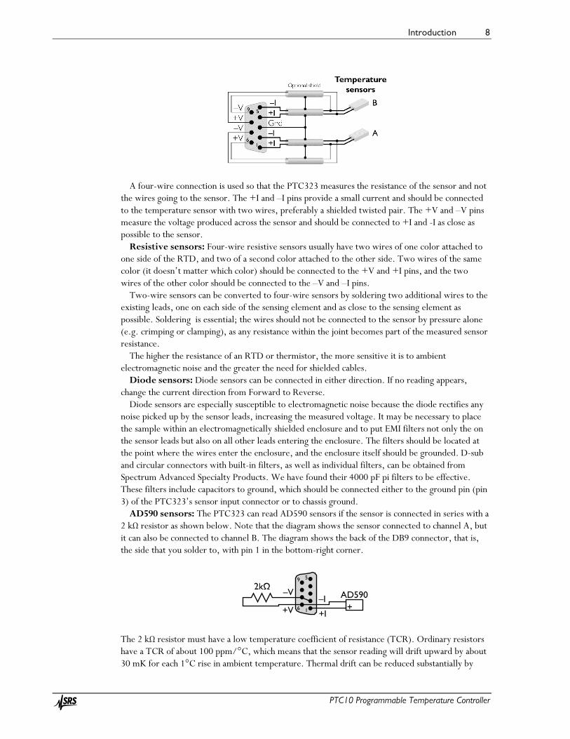
A four-wire connection is used so that the PTC323 measures the resistance of the sensor and not the wires going to the sensor. The +I and –I pins provide a small current and should be connected to the temperature sensor with two wires, preferably a shielded twisted pair. The +V and –V pins measure the voltage produced across the sensor and should be connected to +I and -I as close as possible to the sensor.
Resistive sensors: Four-wire resistive sensors usually have two wires of one color attached to one side of the RTD, and two of a second color attached to the other side. Two wires of the same color (it doesn’t matter which color) should be connected to the +V and +I pins, and the two wires of the other color should be connected to the –V and –I pins.
Two-wire sensors can be converted to four-wire sensors by soldering two additional wires to the existing leads, one on each side of the sensing element and as close to the sensing element as possible. Soldering is essential; the wires should not be connected to the sensor by pressure alone (e.g. crimping or clamping), as any resistance within the joint becomes part of the measured sensor resistance.
The higher the resistance of an RTD or thermistor, the more sensitive it is to ambient electromagnetic noise and the greater the need for shielded cables.
Diode sensors: Diode sensors can be connected in either direction. If no reading appears, change the current direction from Forward to Reverse.
Diode sensors are especially susceptible to electromagnetic noise because the diode rectifies any noise picked up by the sensor leads, increasing the measured voltage. It may be necessary to place the sample within an electromagnetically shielded enclosure and to put EMI filters not only the on the sensor leads but also on all other leads entering the enclosure. The filters should be located at the point where the wires enter the enclosure, and the enclosure itself should be grounded. D-sub and circular connectors with built-in filters, as well as individual filters, can be obtained from Spectrum Advanced Specialty Products. We have found their 4000 pF pi filters to be effective. These filters include capacitors to ground, which should be connected either to the ground pin (pin 3) of the PTC323’s sensor input connector or to chassis ground.
AD590 sensors: The PTC323 can read AD590 sensors if the sensor is connected in series with a 2 kΩ resistor as shown below. Note that the diagram shows the sensor connected to channel A, but it can also be connected to channel B. The diagram shows the back of the DB9 connector, that is, the side that you solder to, with pin 1 in the bottom-right corner.
The 2 kΩ resistor must have a low temperature coefficient of resistance (TCR). Ordinary resistors have a TCR of about 100 ppm/°C, which means that the sensor reading will drift upward by about 30 mK for each 1°C rise in ambient temperature. Thermal drift can be reduced substantially by
AD590
+I16
59
+V
–V–I
+

Introduction 9
PTC10 Programmable Temperature Controller
using a 5 ppm/°C resistor available from SRS; ask for part number 4-02502-457. For even better stability, a 1 ppm/°C resistor such as the Riedon USR2G-2KX1, available from Digi-Key, can be used. In any case, to minimize noise and drift, the resistor should be soldered directly to the pins on the DB9 plug and covered up with the backshell.
Because AD590 sensors are highly sensitive to electromagnetic interference, the AD590 wires and package must be shielded, with the shield connected to pin 3 of the DB9 connector.
Excitation current The PTC323 measures the resistance of the sensor by passing an excitation current through it.
The larger the excitation, the less noise the temperature reading will have. However, if the excitation is too large it will heat the sensor and cause higher than expected readings. Therefore, each channel can be configured for either “low power” or “high power” operation:
• Low power: minimizes sensor heating. This option is mainly for use with thermistors in cryogenic applications. To compensate for the fact that heat conductivity decreases (and thermistor resistance increases) as the temperature approaches absolute zero, the amount of power that the sensor dissipates decreases as the measurement range is increased.
• High power: minimizes noise. Power dissipation is kept roughly constant as the measurement range is increased. This option is for use with RTDs or with any kind of sensor at non-cryogenic temperatures.
• Auto power: uses low power if the sensor type is set to thermistor or ROX, or high power if the sensor type is set to RTD.
The PTC323 has 12 measurement ranges. Within any given range, it generates a constant excitation current as shown in the table below. Note that the range has to be greater than the sensor resistance, so if the sensor resistance is 10 kΩ, for example, the range should be 30 kΩ.
For diode sensors the range is always 2.5V and the excitation current is always 10 µA. The graph below shows how the amount of power dissipated by the sensor depends on the range
and power settings. Sensor heating (degrees above the ambient temperature) is proportional to power dissipation.
Left: the amount of current passed through the sensor by the PTC10; right: the amount of power that the sensor dissipates due to that current

Introduction 10
PTC10 Programmable Temperature Controller
The table below shows some representative noise, electronic accuracy, and self-heating values for free-standing sensors at room temperature. Note that the amount of self-heating can vary dramatically depending on the thermal conductivity of whatever the sensor is attached to or immersed in.
Noise Accuracy Self-heating Low
power High
power Low
power High
power Low
power High
Power 100Ω RTD 20 mK 0.8 mK 640 mK 40 mK 0.09 mK 100 mK
1 kΩ thermistor 2 mK 0.08 mK 60 mK 3 mK 0.009 mK 40 mK 10 kΩ thermistor 2 mK 0.02 mK 50 mK 2 mK 0.0009 mK 25 mK
100 kΩ thermistor 9 mK 0.04 mK 220 mK 3 mK 0.00009 mK 2.5 mK
Noise, accuracy, and amount of self-heating at 25°C for several sensors. “Accuracy” is the electronic accuracy of the PTC10 immediately after calibration and does not account for self-heating or the accuracy of the sensor. “Self-heating” is the rise above ambient temperature of a ~1 mm diameter sensor hanging
by its leads in still air (dissipation constant 1 mW/°C).
The graphs below show how electronic noise varies with temperature for several types of sensors.
RMS noise levels for 100Ω and 1000Ω platinum RTD sensors as a function of temperature. At low power, the 100Ω and 1000Ω sensors have about the same noise level.
Introduction 11
PTC10 Programmable Temperature Controller
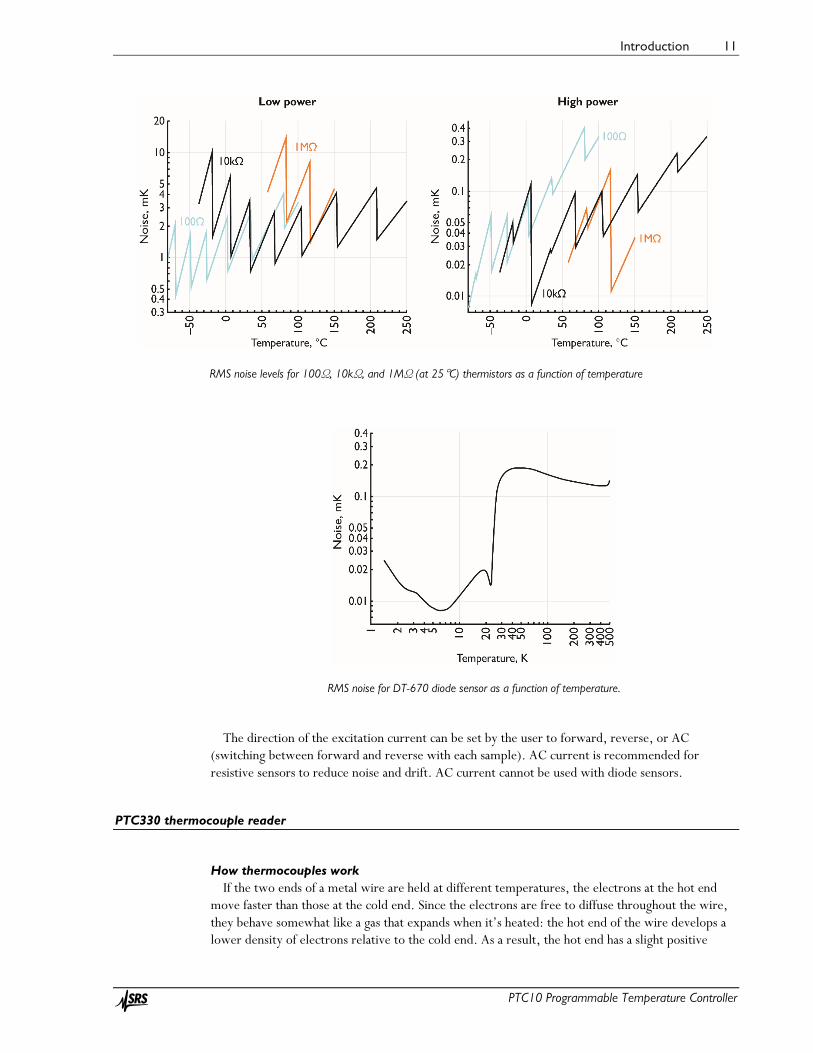
RMS noise levels for 100Ω, 10kΩ, and 1MΩ (at 25°C) thermistors as a function of temperature
RMS noise for DT-670 diode sensor as a function of temperature.
The direction of the excitation current can be set by the user to forward, reverse, or AC
(switching between forward and reverse with each sample). AC current is recommended for resistive sensors to reduce noise and drift. AC current cannot be used with diode sensors.
PTC330 thermocouple reader
How thermocouples work If the two ends of a metal wire are held at different temperatures, the electrons at the hot end
move faster than those at the cold end. Since the electrons are free to diffuse throughout the wire, they behave somewhat like a gas that expands when it’s heated: the hot end of the wire develops a lower density of electrons relative to the cold end. As a result, the hot end has a slight positive

Introduction 12
PTC10 Programmable Temperature Controller
charge and the cold end a slight negative charge, producing a voltage difference. The exact voltage depends on the temperature at each end and the composition of the wire.
A thermocouple has two wires that develop different voltages in response to a given temperature difference. The wires are welded together at one end (the “hot junction”) and the voltage difference is measured at the other (the “cold junction”). If we know the cold junction temperature and if each wire has a perfectly homogeneous composition, we can calculate the hot junction temperature. Normally, we measure the cold junction temperature with another sensor such as an RTD or a thermistor.
Thermocouple calibration tables generally assume that the cold junction is at 0 °C. Therefore, to convert the thermocouple voltage to a temperature, it’s necessary to calculate what the thermocouple voltage would be if the cold junction were at 0°C. For example, say a type K thermocouple is used to measure the temperature of some liquid nitrogen. The thermocouple reader measures a voltage of -6.829 mV and also determines that the cold junction is at 25°C. The calibration table indicates that the voltage of a type K thermocouple at 25°C is 1.000 mV. So we add 1 mV to the reading and look up the result, -5.829 mV, in the calibration table. The result is the temperature of the inaccurately named “hot junction”, -196°C.
Choosing a thermocouple Thermocouples are inexpensive and can sense a wide range of temperatures, but without
frequent calibration they are accurate to no more than 1°C, partly because they tend to oxidize or otherwise react with gases in their environment. Thermocouples made from thinner wires oxidize more quickly and therefore exhibit more calibration drift than heavier-gauge thermocouples.
When selecting a thermocouple type, there’s generally a tradeoff between sensitivity and stability. That is, thermocouples that produce the largest voltages also have the most calibration drift. With the exception of type “B”, the letters that describe thermocouples (E, J, K, etc.) appear to be assigned in order of increasing long-term stability, with type C being the least stable and type T the most. Therefore, if your application requires low noise, it might be best to choose type E; for the best absolute accuracy, type T might be more appropriate.
Each PTC330 input supports one of the following thermocouple types: Type E thermocouples have one chromel (90% nickel, 10% chromium) and one constantan
(60% copper, 40% nickel) wire. It has a large voltage change per degree (68 µV/°C), resulting in excellent signal-to-noise ratio. However, its long-term stability is not very good. Type E thermocouples are resistant to oxidation, but corrode if used in a vacuum or other reduced-oxygen environment.
Type J thermocouples have one iron and one constantan wire. Above 500°C, oxidation of the iron results in poor stability. This thermocouple is mainly used in legacy applications.
Type K thermocouples have one chromel and one alumel (95% nickel, 2% manganese, 2% aluminum, 1% silicon) wire. With a wide temperature range and good stability, it’s the most popular type of thermocouple. Type K thermocouples are resistant to oxidation, but corrode if used in a vacuum or other reduced-oxygen environment.
Type N thermocouples have one “Nicrosil” (nickel with 14% chromium and 1% silicon) and one “Nisil” (nickel with 4.4% silicon and 0.1% magnesium) wire. They are designed for high stability, especially at temperatures above 500°C. However, their sensitivity is low.
Type T thermocouples have one copper and one constantan wire. They are very accurate and can be used in reducing atmospheres, but their temperature range is limited.
The following table summarizes some properties of thermocouples. Two temperature ranges are given: the range that the thermocouple itself can withstand without losing its calibration, and the range supported by the PTC10’s built-in calibration tables, assuming that the cold junction temperature is 25 °C. If the thermocouple temperature is outside the PTC10’s range, no reading

Introduction 13
PTC10 Programmable Temperature Controller
appears on the display and any feedback loops for which the thermocouple is an input do not function.
The “standard calibration” accuracy is the IEC 584-2 standard for thermocouple-to-thermocouple material variation. Not all commercial thermocouples may follow this standard; for example, Omega specifies an accuracy of 2.2°C for its type J and K thermocouples. Greater accuracy is possible if your thermocouple is custom calibrated. The accuracy values in this table only apply to the thermocouple itself and don’t take into account the electronic accuracy of the PTC330.
Temperature range, °C Accuracy
Type Thermocouple PTC10, cold
junction at 25°C Sensitivity,
µV/°C at 25°C
Standard calibration, °C, at 0°C
Custom calibration, °C, <300°C
E –200 to 870 –245 to 1025 60.9 1.7 1 J 0 to 760 –185 to 1225 51.7 1.5 0.1 K –200 to1260 –245 to 1395 40.6 1.5 0.1 N –270 to 1300 –245 to 1325 26.5 1.5 T –200 to 350 –245 to 425 40.6 0.5 0.1
Connecting thermocouples to the PTC330 The PTC330 thermocouple reader is factory-configured to read one of the above thermocouple
types. The thermocouple must be equipped with a miniature jack such as Omega part number SMPW-J-M for type J, SMPW-K-M for type K, etc. The jacks on the PTC330 are color coded according to the American (ANSI) color coding scheme, i.e. type J jacks are black, type K jacks are yellow, etc. The colors may not conform to the standard colors used in other countries.
The thermocouple jacks are connected with thermocouple extension wires to a cold junction block inside the PTC10. The cold junction temperature is measured with a platinum RTD temperature sensor. The cold junction temperature is recorded so that if unexpected drift or other artifacts appear in the thermocouple readings, it can be determined whether the artifacts are due to erratic behavior of the cold junction. If readings are displayed in sensor units (see the System.Other.Units button), the raw thermocouple EMFs are displayed in millivolts, not corrected for the cold junction temperature, and the cold junction temperature is displayed in ohms.
The PTC330’s inputs are optically isolated and the thermocouples can come in direct contact with electrically live metal. In this case, however, the noise level and accuracy of the measurement may be affected.
The PTC330 hardware is calibrated at ambient temperatures of 25 and 35°C. An on-board temperature sensor continuously interpolates between these two calibrations to account for thermal drift of the board’s electronic components. Since the PTC10 enclosure is usually elevated 2 to 3 degrees above ambient temperature, the accuracy of the PTC330 may be compromised if the ambient temperature rises above about 32°C.
To further improve measurement stability, the PTC330 can control the main enclosure fan to keep the card at a constant temperature (see the manual entry for the Channel.PCB control).
PTC420 AC output card
The PTC420 AC output card has a solid-state relay that delivers mains current to the heater. It is intended for control of large heaters including heating mantles, heating tape, and heating blankets. The relay is either on or off; when on, the full AC mains voltage appears on the output. To vary the output power, the PTC420 switches the relay on and then off once every 10 seconds (by default) with a variable duty cycle.

Introduction 14
PTC10 Programmable Temperature Controller
The card can deliver at most 5 A of current. If the resistance of the heater is too small, the card delivers more than its rated current and may be shut down by its internal protection circuitry. In some cases the card may be damaged. The minimum permissible heater resistance depends on the AC line voltage as shown in the table below. The table also shows the maximum power that the card can deliver.
Line
voltage, V
Example locations
Min heater resistance,
ohms
Max power at min heater
resistance, W
Max power at heater
resistance R, W 100 Japan 20 500 10000 / R 120 Canada, US 24 600 14400 / R 220 Russia 44 1100 48400 / R 230 Europe 46 1150 52900 / R 240 China, Australia 48 1200 57600 / R
The total AC current delivered at any one time by the all the PTC420 cards in a single chassis
cannot exceed 10 A. If it does, the PTC10’s main fuse will blow.
PTC430 50 W DC output card
The PTC430 DC output card can deliver up to 50 W of power and is intended for precise control of small heaters. The card offers two voltage ranges (50 V and 20 V) and three current ranges (1A, 0.5A, and 0.1A). An auto-range feature continuously adjusts the current and voltage ranges to the smallest values needed to achieve the power specified with the channel’s Hi Lmt setting.
The PTC430’s maximum power output depends on the resistance of the heater; see the table below.
Heater resistance (R), Ω
Optimum output range
Maximum power, W
> 500 50 V 0.1 A 2500/R 500 50 V 0.1 A 5 100 – 500 50 V 0.5 A 2500/R 100 50 V 0.5 A 25 50 – 100 50 V 1 A 2500/R 50 50 V 1 A 50 20 – 50 50 V 1 A R 20 20 V 2 A 20 10 – 20 20 V 2 A 400/R 10 20 V 2 A 40 < 10 20 V 2 A 4R
Maximum output power and optimum output range as a function of heater resistance
To get the PTC430’s full 50W output, the heater must have a resistance of 50 ohms. If the heater’s resistance is not specified, look for a heater that produces about 265W at 115V or 1060W at 230V.
If the heatsink temperature of a DC output card exceeds 60°C, the card’s internal protection circuitry shuts down the output. This is likely to occur if one of the 50V output ranges is used when the heater resistance is under 20Ω; if the ambient temperature outside the chassis is above 30°C; if

Introduction 15
PTC10 Programmable Temperature Controller
the PTC’s vents are blocked; and/or if the system fan is turned off or not working. If the heater resistance is less than 20Ω, select the “auto” range or one of the 20 V ranges to prevent thermal shutdown.
The temperature of the heatsink can be monitored by setting the System.Display.Monitors button to “Show”, then turning the PTC10 off and back on again. A PCB temperature display should appear on the Select screen directly underneath the current value of the DC output card. If the temperature exceeds 60°C, the card’s output will be shut down.
If the 50 V 1 A range is used and the average heater resistance is less than 65Ω, up to three DC output cards can be installed in a single chassis and run at full power simultaneously. If four DC output cards are installed and the average output current at any given moment exceeds 0.8A, a system reset may occur to protect the power supply from overload.
If any other range is used or the average heater resistance is greater than 65Ω, up to four DC output cards can be installed in a single chassis and run at full power.
Hardware faults The PTC430 continuously monitors for unsafe operating conditions. If such a condition occurs
and persists for more than 2 seconds, the PTC430’s output is shut down. In addition, one of the following error messages appears in a pop-up window on the PTC10’s screen:
• Ground fault: The PTC430’s output is on, and the current flowing out of the card’s positive terminal is not the same as the current flowing into the negative terminal. This error can occur if one of the leads is shorted to an external ground.
• Unexpected output current: The PTC430’s output is off, but current is flowing into the negative terminal anyway. This error may indicate that the heater is shorted to a power source other than the PTC430. It can also indicate a failure of the PTC430’s current output circuitry.
• DC output card overheated: Either the resistance of the heater is too low; the positive and negative terminals are shorted to each other; the PTC10’s chassis fan has been turned off; or the chassis fan is no longer functioning. Try reducing the maximum output voltage or current, and make sure the front panel fan is running.
To re-enable the PTC430’s output, disable the outputs by pressing the Output Enable key, then re-enable the outputs by pressing the Output Enable key twice.
PTC431 100W DC output card
The PTC431 DC output card can deliver up to 100 W of power and is intended for precise control of small heaters. The card offers two voltage ranges (50 V and 20 V) and three current ranges (2A, 0.6A, and 0.2A). An auto-range feature continuously adjusts the current and voltage ranges to the smallest values needed to achieve the power specified with the channel’s Hi Lmt setting.
The 20V range can be used to limit the output voltage for safety purposes. Selecting this range does not otherwise affect the performance of the card. On the other hand, the 0.6A and 0.2A current ranges offer lower noise levels and are intended to be used when very precise temperature control is needed.
The maximum power that the PTC431 can deliver depends on the resistance of the heater as shown below.

Introduction 16
PTC10 Programmable Temperature Controller
Maximum output power as a function of output range and heater resistance
To get the PTC431’s full 100W output, the heater must have a resistance of 25 ohms. If the heater’s resistance is not specified, look for a heater that produces about 530W at 115V or 2120W at 230V.
If the heatsink temperature of a DC output card exceeds 60°C, the card’s internal protection circuitry shuts down the output. This is likely to occur if the heater resistance is under 10Ω; if the ambient temperature outside the chassis is above 30°C; and/or if the system fan is turned off or not working. The PCB temperatures can be monitored by going to the System screen and setting the Monitors control to Show.
Although up to four PTC431 cards can be installed in a chassis, only two can be run at full power at any given time. If more than two PTC431 cards are installed, their output should be limited to half their maximum value, either by using the 20V range or by setting the upper limit to 50W.
Hardware faults The PTC431 can detect certain unsafe operating conditions. If such a condition occurs and
persists for more than 2 seconds, the PTC431’s output is shut down (to re-enable the output, disable all outputs by pressing the Output Enable key, then re-enable the outputs by pressing the Output Enable key twice). In addition, one of the following error messages appears in a pop-up window on the PTC10’s screen:
• Measured heater current differs from desired value: The PTC431’s output is on, and the current at the positive terminal differs from the desired current by more than 0.25A. This error can occur if the card is out of calibration. It can also mean that the card has been damaged and is no longer capable of correctly regulating its output current or of producing its rated output current.
• Current at + and – heater terminals is different: The PTC431’s output is on, and the current at the positive terminal differs from the current at the negative terminal by more than 0.25A. This error can occur if one of the leads is shorted to an external ground.
• Output is off but heater current was detected: current is flowing into the negative terminal even though the positive terminal isn’t producing any current. This error may indicate that the heater is shorted to a power source other than the PTC10. It can also indicate a failure of the card’s current output circuitry.
• Output card overheated: Either the resistance of the heater is less than 10 ohms; the positive and negative terminals are shorted to each other; the ambient temperature is too

Introduction 17
PTC10 Programmable Temperature Controller
high; or the PTC10’s chassis fan is not working. Try reducing the maximum output voltage or current, and make sure the front panel fan is running.
PTC440 TEC driver
The PTC440 includes a current source to drive a thermoelectric cooler and a sensor input for a thermistor, RTD, or IC temperature sensor. The card has a single 15-pin D-sub connector for both sections. The pinout and wiring diagram are shown below. Only pins 1 and 3 need to be connected to power a TEC device, and only pins 8 and 14 need to be connected to read a temperature sensor. The other pins are optional.
TEC driver section A thermoelectric cooler (TEC), also referred to as a Peltier device, is a solid-state electric heat
pump that can both heat and cool, depending on the direction of current flow. Thermoelectric coolers are generally used for precise temperature control of small objects in the range of -100–100°C.
With its high-current, low-voltage output, its ability to change the direction of current flow, and circuitry to protect the TEC from excessive voltages, the PTC440 is primarily intended to drive TEC devices. However, it can also drive low-resistance (optimally 2.4 ohm) resistive heaters. In this case, the lower output limit should be set to 0 A and the heater should be connected to pins 1 and 3.
If the TEC is unplugged while current is flowing, or if the current is turned on when no TEC is present, the card’s output is disabled and remains disabled until its output is set to zero. This feature ensures that the voltage between the output terminals is always zero when a TEC is plugged in. A nonzero voltage would produce a destructive current spike when the TEC is plugged in.
Therefore, if the PTC440 does not produce any output current, turn the current off and back on again, either by pressing the PTC10’s “Output Enable” button three times or setting the output value to zero with the Channel.value control.
Connecting the TEC Connect the + and – leads of the TEC to pins 1 and 3, respectively. Pins 2 and 4 can also be
connected to reduce contact resistance. The PTC440 is a current source, that is, it has direct control over the current that passes through
the TEC but not the voltage. Since thermoelectric coolers are easily destroyed by both voltages and currents even slightly above their rated maximum, the PTC440 provides a voltage input (Vmon) to

Introduction 18
PTC10 Programmable Temperature Controller
monitor the TEC voltage. The connections for this input are the TEC sense + and TEC sense – pins. If these leads are connected to the TEC + and – leads, as close to the TEC as possible, Vmon shows the voltage across the TEC. If the leads are not connected, Vmon shows the voltage at the PTC’s back panel.
If only a small current passes through the TEC even at its maximum voltage, the TEC may have been damaged by excessive current or voltage.
Maximum TEC voltage The TEC driver has four voltage ranges: 3, 6, 9, and 12V. In general, the lowest possible voltage
range should be used; besides potentially damaging the TEC, the larger voltage ranges create excess heat inside the PTC chassis and cause the PTC’s fan to run at high speed.
However, when selecting a voltage range, it's important to account for the resistance of the wires you've used to connect the TEC. This resistance can significantly reduce the voltage available to the TEC. For example, if the wires have a resistance of 0.5 ohms and a 5A current is flowing through them, the wires will reduce the available voltage by 2.5V. Therefore, if the 3V range is selected, the maximum voltage across the TEC will only be 0.5V. If the TEC sense leads have been connected, this is the maximum voltage that will appear in the Vout display.
To minimize such voltage losses, heavy-gauge wires should be used to connect the TEC. Standard DB-15 cables in particular should not be used because their thin wires absorb most of the PTC440's output power.
The Vmon channel has a voltage limit, Vmax. If the voltage at the TEC exceeds Vmax, the PTC440's output is shut off. The output will remain disabled until it is set to zero using either the Output Enable key or the “off” button on the Channel Setup screen. If the sense leads have been connected, the lead resistance does not have to be taken into account when setting Vmax.
In some cases, the output may exceed Vmax every time the PID feedback is enabled. To avoid this, temporarily set the ramp rate to a low value (i.e. 1 °C/s) when enabling the feedback.
Temperature input section The PTC440 has a sensor input that can read thermistors, RTDs, AD590, and
LM135/LM235/LM335 temperature sensors. The PTC440’s temperature input is not intended for precision applications and should only be used when temperature stability of ~0.1°C is acceptable. For more demanding applications the sensor should be read with a dedicated input card such as the PTC320 (for thermistors, RTDs, and diodes), PTC321 (for 100 Ω RTDs only), or PTC330 (thermocouples). These cards provide lower noise and greater accuracy than the PTC440.
Connecting the temperature sensor RTDs: 4-wire RTDs should be used to ensure accuracy. Two of the wires are normally white
and are connected to one end of the resistive sensor, while the other two are black, red, or yellow and are connected to the other end. There is normally no shield. In this case, the RTD should be wired in one of the following ways (assuming black and white wires):
Pin 7 Pin 8 Pin 14 Pin 15
Option 1 White Black White Black Option 2 Black White Black White
Thermistors: Two-wire thermistors should be connected to pins 8 and 14.

Introduction 19
PTC10 Programmable Temperature Controller
LM135/LM235/LM335: The LM135, LM235, and LM335 are integrated circuit temperature sensors. If an excitation current between 400 µA and 5 mA is passed through the sensor, the voltage drop across the sensor is 10 mV/K. The three models have different temperature ranges, with the LM135 having the largest range and the LM335 the smallest. For the best possible accuracy the sensors can be connected in a 4-wire configuration, just like an RTD. However, it is more common to connect the device in a 2-wire configuration, leavings pins 14 and 15 of the PTC440 unconnected. The first row of the table below lists the four sensor input pins on the PTC440’s output connector; the second and third rows show which leads of the LM135/235/335 should connect to those pins.
Pin 7 Pin 8 Pin 14
(optional) Pin 15
(optional) 8-pin SOIC Pin 8 Pin 4 Pin 8 Pin 4 Other packages + – + –
AD590/AD592: The AD590 and AD592 are an integrated circuit temperature sensors. When a
voltage between 4 and 30V is applied to the device’s two terminals, a current of 1 µA/K flows through the device. The two models have different packages and temperature ranges, with the AD590 having a range of -55 – 150°C and the AD592 a range of -25 – 125°C. The AD590/592 can be connected in a 2- or 4- wire configuration as shown in the table below. For the 2-wire configuration, leave PTC440 pins 14 and 15 disconnected.
Pin 7 Pin 8 Pin 14
(optional) Pin 15
(optional) 8-pin SOIC Pin 2 Pin 3 Pin 2 Pin 3 Other packages + – + –
Sensor excitation current The excitation current provided to resistive sensors can be set to 10 µA, 100 µA, 1 mA, or auto.
In auto current mode, the sensor resistance is continuously monitored and the excitation current is adjusted whenever the sensor resistance rises above or drops below the levels shown in the table below. The “auto” setting always produces a 10 µA excitation when a diode sensor is in use, or 1 mA when an LM335 or AD590 sensor is in use.
Sensor
resistance Excitation
current <2 kΩ 1 mA 1– 20 kΩ 100 µA >10 kΩ 10 µA
Excitation current produced by the “auto” current setting on the PTC440 TEC driver (for resistive sensors only)
Note that the resistance ranges overlap; if the sensor resistance is between 1 and 2 kΩ, for example, the TEC driver can use either 1 mA or 100 µA excitation. If possible, the excitation current is kept at its previous value.
A slight temperature glitch may occur when the PTC440 switches from one range to the next. If these glitches could disrupt your experiment, set the excitation current manually.
Introduction 20
PTC10 Programmable Temperature Controller
A/D rate Some TECs are capable of very fast response rates. If the temperature of your TEC changes very
quickly (on the order of 1 second) when a current is passed through it, it’s recommended to reduce the system A/D rate (set with the System.Other.A/D rate command) from its default 100 ms to 50 ms. Operating the PID feedback loop at a faster rate allows it to more precisely control the system temperature and, therefore, results in a more stable temperature.
PTC510 analog I/O card
This card is included as standard equipment and fits in either of the two narrow I/O card slots. Each of its four channels can be either an input (±10V, 24-bit ADC) or an output (±10V, 16-bit DAC). Each channel has a red back-panel LED that lights up when the channel is an output.
The analog I/O channels can be used as PID inputs or outputs. Since each channel can only supply up to 10 mA of current, the analog I/O can’t be used to drive a heater directly, but can be connected to an external amplifier.
If the I/O type of an analog I/O channel is “set out” or “meas out”, buttons to configure the channel’s PID feedback appear on the Channel Setup screen. The corresponding remote instructions are also available. If the channel’s I/O type is “input”, the PID instructions are not available and the PID feedback loop is disabled. Instead, controls and remote instructions for an alarm, lowpass filter, difference filter, time derivative, and offset/gain calibration appear. These controls disappear, the remote instructions are not available, and the functions are disabled when the channel is an output.
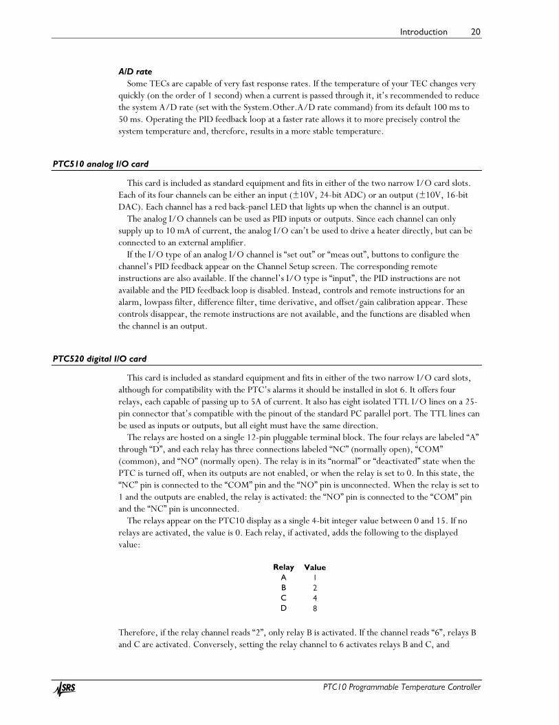
PTC520 digital I/O card
This card is included as standard equipment and fits in either of the two narrow I/O card slots, although for compatibility with the PTC’s alarms it should be installed in slot 6. It offers four relays, each capable of passing up to 5A of current. It also has eight isolated TTL I/O lines on a 25-pin connector that’s compatible with the pinout of the standard PC parallel port. The TTL lines can be used as inputs or outputs, but all eight must have the same direction.
The relays are hosted on a single 12-pin pluggable terminal block. The four relays are labeled “A” through “D”, and each relay has three connections labeled “NC” (normally open), “COM” (common), and “NO” (normally open). The relay is in its “normal” or “deactivated” state when the PTC is turned off, when its outputs are not enabled, or when the relay is set to 0. In this state, the “NC” pin is connected to the “COM” pin and the “NO” pin is unconnected. When the relay is set to 1 and the outputs are enabled, the relay is activated: the “NO” pin is connected to the “COM” pin and the “NC” pin is unconnected.
The relays appear on the PTC10 display as a single 4-bit integer value between 0 and 15. If no relays are activated, the value is 0. Each relay, if activated, adds the following to the displayed value:
Relay
A B C D
Value 1 2 4 8
Therefore, if the relay channel reads “2”, only relay B is activated. If the channel reads “6”, relays B and C are activated. Conversely, setting the relay channel to 6 activates relays B and C, and

Introduction 21
PTC10 Programmable Temperature Controller
deactivates the other relays. To set an individual relay from a macro or serial port without affecting the states of other relays, use a bitwise operator; for example, the remote command
relays |= 4
activates relay C, while the remote command
relays &= 11
deactivates relay C. See the “Remote programming” section of this manual for more information on remote commands.
The eight TTL lines are located on a standard 25-pin D-sub connector with the following pinout (the pin numbers are usually printed next to the pins on D-sub connectors):
1 Unconnected
2 D0 3 D1 4 D2 5 D3 6 D4 7 D5 8 D6 9 D7 10 +5V 11 +5V 12 Gnd 13 Unconnected
14 Unconnected 15 Unconnected 16 Unconnected 17 Unconnected 18 Unconnected 19 Gnd 20 Gnd 21 Gnd 22 Gnd 23 Gnd 24 Gnd 25 Gnd
Since the digital I/O lines are floating, at least one “gnd” pin must be connected to the signal
ground of whatever system the digital I/O is interfaced with. Alternatively, if the digital I/O lines are configured as inputs, a +5V pin can be shorted to any of the inputs D0 to D7 to pull them high, or a “gnd” pin shorted to the inputs to pull them low. The +5V pins are current-limited with 4.7 kΩ resistors and are not intended to power a remote system.
The status of the eight digital I/O lines is reported on the PTC10 display as a single eight-bit integer value. Each I/O line is assigned an integer value as shown in the following table:
Bit
D0 D1 D2 D3 D4 D5 D6 D7
Value 1 2 4 8
16 32 64
128
The “DIO” value shown on the PTC10’s display is the sum of the values of all set bits. For
example, if only bits D1 and D3 are set, a DIO value of 2 + 8 = 10 is displayed. Using the remote interface, macros can be defined that associate the digital I/O lines with most
functions of the PTC10. The remote interface provides bitwise operators to set and query the relays and digital I/O lines.

Introduction 22
PTC10 Programmable Temperature Controller
The DIO lines can be used to pass a single, 8-bit value into or out of the PTC. The PTC treats the DIO like any other channel; for example, its value can be plotted or used in a PID feedback loop.
Virtual channels The digital I/O card has three virtual channels with the default names V1, V2, and V3. These
channels are not connected to any physical inputs or outputs. Instead, macros or remote commands can assign arbitrary values to these channels, or the channels can automatically follow the value of another channel. Like “real” channels, the values of virtual channels can be plotted on the Plot screen, displayed on the Numeric screen, and logged to RAM and USB.
Each virtual channel can either an input or an output (see the Channel.IO Type button). If it’s an input, a virtual channel can follow the value of another channel (see the Channel.Follow button), and its value can be modified by applying a lowpass filter, subtracting a difference channel, taking its derivative with respect to time, or applying offset/gain factors. By doing these calculations on a virtual channel that has been configured to follow a sensor input (instead of doing them directly on the sensor input channel), the raw sensor input is preserved and can still be viewed.
If the virtual channel is an output, it has a PID feedback loop that can be used for cascade control (see the description of the Channel.PID.Casc button in the Operation section). Unlike other outputs, virtual outputs aren’t forced to zero when the PTC’s outputs are disabled with the Output Enable button. However, virtual PID feedback loops do stop running when the PTC10’s outputs are disabled.
When the value of a virtual channel is changed by a macro or from the front panel, the new value does not become effective until an ADC conversion occurs. Therefore, if a macro sets the value of a virtual channel and then immediately reads the value back, the old value may be returned.

Operation 23
PTC10 Programmable Temperature Controller
Operation

Operation 24
PTC10 Programmable Temperature Controller
Quick start tutorial
Turn the instrument on
Plug the PTC10 in and turn it on with the power switch located next to the AC power inlet. If the PTC10 does not turn on, a fuse may have blown. Check the fuse holder just above the
on/off switch. If the instrument turns on but does not respond to button or touchscreen presses, the most likely
cause is that the ground prong of the electrical socket is not connected to ground. A three-prong plug must be used and all three prongs must be connected.
The Select screen
Each of the green buttons on this screen represents one I/O channel. The buttons are arranged in roughly the same order as the connectors on the back of the PTC10. Each button shows the channel’s name and current value. If no sensor or heater is connected, the value may be blank.
Some of the buttons represent internal data channels. In the figure above, for example, the
thermocouple card has a button for the cold junction temperature. “V1”, “V2”, and “V3” are virtual channels that can be used for calculations. It’s also possible to display heater current, voltage, and resistance; use the “Monitors” control on the System Setup screen to enable this option.
Buttons turn red whenever the channel’s alarm is triggered. The name of the channel appears in bold if the channel uses a custom calibration table.
Touch one or more buttons to select which channels to show on the Numeric, Plot, and Channel screens.
Configure the sensor inputs
If you’re using a PTC320 or PTC323 thermistor/diode/RTD input card, it may be necessary to select the sensor type and calibration curve.
1. Select one or more inputs on the Select screen.

Operation 25
PTC10 Programmable Temperature Controller
2. Press the “Channel” key to display the channel settings screen. The top of this screen has one tab for each selected channel. Touch one of the tabs to display the settings for that channel.
3. Touch the “Sensor” button and select the appropriate sensor type (RTD, thermistor, diode, etc.)
4. Set the Range to “Auto”. 5. In the “Cal” column, touch the “Type” button and select the appropriate calibration curve.
If the sensor reading does not appear
The sensor reading is blank whenever it falls outside the limits of the calibration data or input hardware. This normally occurs when no sensor is connected, but can also occur if the sensor is incorrectly configured. In this case, try the following steps:
1. Ensure that the sensor is correctly connected. Thermistors and RTDs should normally be connected with four wires. Thermocouples and diodes must not be connected backwards.
2. Measure the resistance of the sensor with an ohmmeter to ensure that one of the wires is not broken.
3. Bring up the channel setup screen for the input channel and check the following settings: Sensor: must agree with the type of sensor that is in use. Range: set to Auto or, if a fixed range is selected, make sure it’s larger than the sensor
resistance. Current: Forward, Reverse, or AC. If the current is off, no sensor reading will appear. Cal Type: must agree with the type of sensor that is in use. Cal R0: for RTDs only; must agree with the type of sensor that is in use. 4. Go to the System Setup screen and change the Units to “Sensor”. Now the reading will
appear in ohms or volts instead of degrees. Is the value correct? 5. If you’re using a custom calibration table, make sure that the sensor resistance or voltage is
within the range of the calibration table. 6. If you’re using a resistive sensor and the reading in ohms is incorrect, remove the sensor and
instead connect a resistor of about the same value to the PTC10. If the reading is still incorrect, the unit may need to be returned to SRS for recalibration.
Plot data
To plot data on-screen:
1. On the Select screen, touch the buttons to highlight the channels that you’d like to plot. 2. Press the Plot key on the PTC10’s front panel.
Once the Plot screen is showing, press the Plot key repeatedly to cycle between four screen arrangements:
• One plot for each channel • All channels on a single plot • Ponytail plot: all channels on a single plot, offset such that each channel starts at zero • Custom: channels are assigned to plots with the “Plot” button on the channel setup screen,
described on page 65.

Operation 26
PTC10 Programmable Temperature Controller
Touch anywhere within the right half of the plot to zoom in. To zoom out, touch the left half of the plot (but not left of the Y axis). Drag left and right to pan; touch the words “X lock” that appear in the bottom-left corner of the screen to return to viewing real-time data.
Test the outputs
Before trying to run a PID feedback loop for the first time, it’s helpful to verify that your heater is working by setting its current or power to a low value and seeing if any current flows. To do this, plug your heater into the PTC10’s back panel and set the output as follows:
1. Enable the outputs by pressing the Output Enable key twice. The red Output Enable light should turn on.
2. Select the output channel on the Select screen, then press the Channel key to display the channel setup screen.
3. If you’re using one of the ±10V analog I/O channels to drive your heater, make the channel an output by changing its IO type to “meas out”.
4. Touch the Value button and enter a small value for the current or power (one that won’t damage your system).
5. The Value button should display the value that you entered. If it’s blank or displays zero, the PTC is not detecting the heater.
6. Verify that your heater is warming up. 7. To turn the current off, touch the Off button on the channel setup screen.
If the Value button is blank or the heater doesn’t start warming up, try the following:
• Verify that the heater leads are not shorted to ground or to each other. • If the heater is resistive, unplug it from the PTC10 and measure its resistance with a
multimeter. Make sure that the resistance is appropriate for the output card: • PTC420 AC output card: 24Ω – 300Ω (120VAC), 46Ω – 600Ω (230VAC) • PTC430 50W DC output card: 1Ω –1kΩ • PTC431 100W DC output card: 10Ω – 1kΩ
• Display the heater resistance: go to the System screen and, in the “Display” column, touch the “Monitors” button and select “Show”. Return to the Select screen. Underneath the heater power there should now be buttons for heater current (labeled “I 1” if the heater output card is in slot 1), voltage (“V 1”), and resistance (“R 1”). Turn the heater on again. Is the heater resistance the same as what you measured with a multimeter? Is the voltage or current at the maximum that the output can produce?
• Verify that the PID mode is set to off. • On the channel setup screen, make sure that the output’s hi limit and range are both greater
that the output value that you entered. • If the output is a PTC440 TEC driver, disable and re-enable the outputs. The PTC440’s
output is automatically disabled if you try to output a current when no TEC device is connected, or if the voltage exceeds the Vmax setting.
• If you’ve previously set up an alarm (see “Configure the alarm”, below), it could be disabling the output. For example, if you move a sensor from one input to another, remember to disable the alarm on the old input.

Operation 27
PTC10 Programmable Temperature Controller
Set the data logging rate
By default, the PTC10 records ten data points per second to each channel’s log. To change this rate, press the System key on the front panel. Under the “Log” column, touch the “Interval” button and select from the list of available options
The log interval determines the maximum length of time that can be displayed on the PTC10’s plot screen. The PTC10 stores up to one million data points for each channel in its on-board memory, while older data points are erased. At the default logging interval of 0.1 seconds, the PTC10’s graph can display about the last 27 hours of data. If the logging interval is 1 second, up to 11 days of data can be displayed. The logging interval has to be set before the data is acquired; all on-board data is erased when the logging interval is changed.
The log interval also determines how much time a single log file can cover; see the next section below.
It’s also possible to assign a different log interval to each channel; see the description of the Channel.Logging control on page 65.
Save data to and retrieve data from a USB memory device
A USB memory stick can be used to keep a permanent record of logged data. Data is logged to an ASCII file. The default name of the log file is \Log\00\Log00.csv (the top-
level directory name, “Log”, can be changed from the front panel). The file is an ASCII CSV (comma-separated value) file that can be read with spreadsheet software.
The maximum size of the file is 2GB for FAT-formatted USB devices or 4 GB for FAT32 devices. The file can reach this size in as little as 6 days, but more typically it should take about 30 days. When the file fills up, Log00.csv is closed and the PTC10 automatically begins writing data to a new file named Log01.csv. If Log99.csv fills up, the PTC10 begins logging to a new directory named “\Log\01” (where “Log” is the top-level directory name).
Save data to a USB device
1. Plug the USB memory stick into the port on the back of the instrument. 2. Wait about 5 seconds until the message “Please wait while the USB drive is opened” appears
on-screen. The message stays on-screen for several seconds while the log files are opened, then the message disappears.
3. Look for a small, dark red circle in the upper-right corner of the screen. This is the USB logging indicator. Touch the circle. When it turns light red, the PTC10 is saving data to the USB device.
4. Before turning the instrument off or removing the USB device, touch the USB logging indicator again and wait for it to turn dark. This step is very important to prevent damage to the USB device. If this step is skipped, the USB device should be re-formatted in a PC before using it again.
View saved data on a PC A software package that can be downloaded from the SRS website (www.thinksrs.com, click
Downloads > Software) includes a program that plots log files. No installation is required; just double-click the “FileGrapher” icon or drag a log file onto it.

Operation 28
PTC10 Programmable Temperature Controller
Interface with a computer
The System setup menu, which can be displayed by pressing the “System” button on the PTC10’s front panel, has controls for setting up the PTC10’s RS-232, USB, GPIB, and Ethernet interfaces (under the “COM” and “IP” columns).
The USB port uses an FTDI USB chip. If the PC asks for a driver, follow these instructions:
Install the USB driver for Windows PCs
1. Download and install the appropriate FTDI Virtual Com Port (VCP) driver from:
http://www.ftdichip.com/Drivers/VCP.htm
2. Optional: the default baud rate for the FTDI driver is 9600. For faster communication, change the baud rate to 230400 on both the PC and the PTC10. On the PTC10, press the Setup key, touch the System tag, and select the “USB” button. Select 230400. On the PC, change the baud rate setting in whatever software that you’re using; if there’s no such setting, open the Device Manager and expand the Ports line. Plug the PTC10 into the PC and look for a new port to appear. Double-click that port, select the Port Settings tab, and change “bits per second” to 230400.
3. The PTC10 should now appear as a COM port on your computer, and your programs can use the USB connection in the same way that they use an RS-232 connection.
Read data from the PTC10 All RS-232, GPIB, USB, and Ethernet messages sent to the PTC10 must end with a linefeed
(decimal 10 = hex 0x0a = ‘\n’). The PTC10 will not process the message until the linefeed is received. Instructions are not case-sensitive.
The most recent value (i.e., the value read at the most recent ADC conversion) of a single channel can be queried by sending the name of the channel, followed by a question mark.
3A? 29.9313
Omit any spaces from the channel’s name; for example, to query the value of channel “Out 1”, send the command:
Out1? 0.00000
The most recent value of all channels can be retrieved with a single getOutput instruction (the question mark is optional in this case):
getOutput? 0.000000, 0.000000, 29.98424, 25.86019, 27.49236, NaN, 27.45483, NaN, 268.9367, NaN, NaN, 0.000000, 10.04576, 10.04574, 10.04572, NaN, NaN, NaN, 0, 0
Sensors that are disconnected or out of range report a value of “NaN” (not a number). To determine the order of the channels in the getOutput response, send the getOutputNames query:
getOutputNames?

Operation 29
PTC10 Programmable Temperature Controller
Out 1, Out 2, 3A, 3B, 3C, 3D, Cold J 3, 4A, 4B, 4C, 4D, 5A, 5B, 5C, 5D, V1, V2, V3, DIO, Relays
This order does not change unless I/O cards are added, removed, or rearranged. A third option for reading data is the getLog instruction, which returns the latest data point
written to the log. By default, a logged value is the average of ten ADC conversions. Therefore the values returned by getLog are not as noisy as the values returned by the getOutput and <channel>? instructions, both of which return the result from the most recent ADC conversion only. In addition, getLog makes it easier to retrieve data acquired at consistent time intervals. For example, begin by sending this command, which retrieves the last point in channel 3A’s log:
getLog "3A", last 27.53936
Note that the channel name must be in quotes if it contains a space. Next, send the following command:
getLog "3A", next 27.57375
Each time this command is sent, the PTC10 waits until a new point is added to channel 3A’s log, then returns the new data point.
Control a temperature
The PTC10 can control the temperature of one or more external devices. Each device must include a heater or cooler, and a temperature sensor that monitors the temperature of whatever is being heated or cooled.
Each of the PTC10’s output channels has a proportional-integral-differential (PID) feedback algorithm that can monitor a temperature reading and determine how much power to send to the heater or cooler. The algorithm uses a set of three gain factors to determine how much and how quickly the heater or cooler power should be adjusted when the temperature deviates from its desired value. These gain factors must be properly set before the PTC10 can control the temperature of your system.
Start by plugging the heater and temperature sensor into the PTC10’s back panel. The sensor must be in thermal contact with the heater — the better the thermal contact is, the more precise the temperature control will be.
Enable the lowpass filter Adding a lowpass filter to the temperature input usually improves feedback performance. On the
Select screen, touch the buttons for the heater output and the sensor input that you plan to use, making sure that they and no other channels are highlighted. In this example, we’re using heater “Out 2” and thermocouple input “3A”:
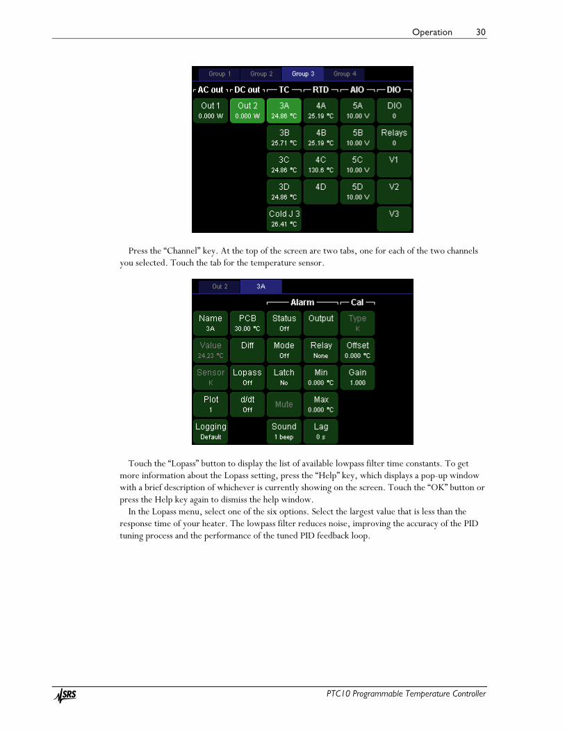
Operation 30
PTC10 Programmable Temperature Controller
Press the “Channel” key. At the top of the screen are two tabs, one for each of the two channels you selected. Touch the tab for the temperature sensor.
Touch the “Lopass” button to display the list of available lowpass filter time constants. To get more information about the Lopass setting, press the “Help” key, which displays a pop-up window with a brief description of whichever is currently showing on the screen. Touch the “OK” button or press the Help key again to dismiss the help window.
In the Lopass menu, select one of the six options. Select the largest value that is less than the response time of your heater. The lowpass filter reduces noise, improving the accuracy of the PID tuning process and the performance of the tuned PID feedback loop.

Operation 31
PTC10 Programmable Temperature Controller
Configure the alarm To protect your system from runaway feedback (overheating that can occur if, for example, the
PID feedback is configured incorrectly or the sensor becomes disconnected), it’s important to set up an alarm. The alarm automatically shuts off the heater whenever the temperature exceeds limits that you specify, whenever the sensor becomes disconnected, and whenever the temperature becomes too high or low for the sensor to measure. On the Setup screen for your temperature sensor, under the Alarm heading, set the options as follows:
• Status: This button indicates if the alarm is currently triggered. It can be used to turn off latching alarms, but it doesn’t have any effect on non-latching alarms.
• Mode: Set to “on” to enable the alarm. • Latch: Set to “no”. A latching alarm, once triggered, must be turned off manually. • Sound: 1 beep. • Output: select the heater output channel. The selected channel will be forced to zero
whenever the alarm is beeping, preventing “runaway feedback” from overheating your system if the sensor is disconnected or incorrect feedback parameters are entered.
• Relay: For the best possible security, the output should be routed through one of the four relays (A, B, C, or D) and the Relay button should be set to A, B, C, or D accordingly. The relay will physically disconnect the heater whenever the alarm is beeping.

Operation 32
PTC10 Programmable Temperature Controller
• Min: If the PTC10 is controlling a thermoelectric cooler, set the min to the lower temperature limit of your system. Otherwise, this value should be set well below the lowest temperature that could normally be produced, so that the min setting can only be exceeded if something is wrong with the sensor.
• Max: Set to the upper temperature limit of your system. • Lag: Set to 1 s. This will prevent small glitches, such as those caused by autoranging, from
triggering the alarm.
Configure the PID feedback loop The next step is to tell the instrument which temperature sensor to control and the desired
temperature of that sensor. The PID loop is configured from setup screen of whichever channel you want to use as the heater
output. To display this screen, press the “select” button and make sure the output that you want to use is selected. It’s OK if other channels are selected too; they won’t have any effect on the PID configuration. For this example, we’ll configure channel Out 2.
Now press the “Channel” button and touch the blue tab for the output channel that you want to use, “Out 2” in this example. You should see the channel setup screen for channel Out 2:

Operation 33
PTC10 Programmable Temperature Controller
Select which temperature sensor you want to control: in the first “PID” column, touch the “Input” button. A window showing all available input channels appears. Touch the button for the temperature that you want to control, “3A” in this example. Sensor 3A is now the PID input for heater Out 2.
Next, touch the “Setpoint” button and enter the value that you want the temperature to be driven to. Touch “OK” once you’ve entered the setpoint. The temperature won’t actually start to change yet because the PID mode should still be set to “off”.
Configure the feedback autotuner The feedback tuner changes the heater output and measures how much the temperature changes
in response. Before this can be done, the PTC10 needs to be told how much the heater output should be changed and indicate how long it should wait for the temperature to change.
Go to the Channel setup screen for the heater channel and look at the “Tune” column. If the output is increased to the value shown in “Step Y”, would you expect to see a noticeable rise in temperature within the time shown in “Lag”? Would the amount of power shown in “Step Y” damage your system? Change these values if necessary.
Touch “D” and set the derivative gain to 1. Any nonzero value tells the tuner to enable derivative feedback, which makes the feedback faster but can also add noise. If D is set to zero, the tuner uses

Operation 34
PTC10 Programmable Temperature Controller
a different tuning algorithm that leaves derivative feedback disabled. This is sometimes necessary to reduce noise in the feedback output.
Start the feedback autotuner If the system has never been tuned, start with the feedback turned off and the heater at ambient
temperature. If the system has been tuned before, it’s better to enable the feedback and wait for the temperature to stabilize at the setpoint. In either case, the key to successful autotuning is to start with a stable temperature.
If starting at ambient temperature, ensure that the feedback is turned off before enabling the outputs: select the output channel on the “Select Channels” screen, then press the Setup key, select the tab for the output channel, and touch the “Off” button.
If the outputs are disabled, enable them by pressing the “Output Enable” key twice. The red Output Enable LED turns on and the PTC10 beeps (if pressed again, the Output Enable key immediately turns all the PTC10’s outputs off; inputs are not affected).
In the PID menu, set the Mode to “auto” to start the autotuner. A status window appears and is updated every few seconds.
Before it begins the actual tuning process, the PTC10 verifies that the Step Y and Lag settings actually change the temperature by a significant amount, and cancels tuning if they don’t. The figure below shows how this is done.
During the first stage of autotuning, the PTC10 compares how much the temperature changes before vs. after turning the heater on. Autotuning is cancelled if the temperature doesn’t change 10x more after the heater is
turned on.
The PTC10 first locks the heater output at its current value for one-third of the Lag time and
measures how much the temperature changes. This measurement is the noise and drift. It then increases the heater output by Step Y and waits for the Lag time to elapse. If the temperature doesn’t change by at least ten times the noise and drift, autotuning is automatically cancelled, the heater output is returned to its original value, and no changes are made to the feedback gains. If the Status window is showing, it displays a message that says “Tuning was cancelled because the response was less than 10 times the noise and drift”. The cause of the problem may be one or more of the following:

Operation 35
PTC10 Programmable Temperature Controller
• Raising the heater output by Step Y didn’t significantly increase the temperature, in which case Step Y should be increased;
• The Lag time wasn’t long enough for the heater to respond, in which case it should be increased; or
• The temperature was drifting up or down as the test began, in which case the heater should be left to stabilize at room temperature before trying to tune again.
It’s OK to dismiss the status window or otherwise use the PTC10 during tuning; tuning will continue unless you turn tuning off or disable the outputs with the Output Enable key. In fact, it’s a good idea to display a graph of heater output and temperature while autotuning (select the two channels, press the “Show Data” key, and select the “Multiple” tab). To see the status message again, press the “Setup” key, select the tab for the output channel, and then touch the “Status” button in the bottom-right corner.
When tuning is finished, the PTC10 beeps and the PID feedback is automatically enabled. If the temperature is still below the setpoint, the PTC10 starts increasing power to the heater. The temperature may overshoot the setpoint, but should eventually stabilize at the setpoint.
The feedback should be re-tuned when:
• There is a large change in the temperature • The temperature units are changed (e.g. from °C to °F) • The output units are changed (e.g. from W to A) • The lowpass filter setting is changed

Operation 36
PTC10 Programmable Temperature Controller
Acquiring and logging data
Input filters
The PTC10 offers several numeric filters for processing sensor readings. Except for the sensor calibration, the filters are disabled by default and can be enabled by the user. In the order in which they are applied, the filters are:
1. Sensor calibration (converts sensor reading in ohms, volts, etc. to temperature) 2. Follow filter (virtual channels only; makes the channel equal to another channel. Not the
same as the PID follow mode.) 3. Offset/gain (multiplies a channel by a gain and adds an offset) 4. Difference (subtracts the value of another channel) 5. Lowpass (filters out noise) 6. Derivative (takes the derivative of the signal with respect to time)
The filters can interact with each other. For example:
• If the settings of filters 1–4 are changed and the lowpass filter is enabled, the effect of the new setting on the sensor reading is lowpass filtered.
• Changing the gain may have unpredictable results if the difference filter is enabled, and changing the offset has no effect if the derivative filter is enabled.
• Custom calibration tables have no effect if the follow filter is enabled.
Custom calibration tables
If none of the PTC10’s built-in sensor calibration curves are appropriate for your sensors, a custom calibration table can be used to convert the raw sensor reading in ohms, volts, etc. to a temperature. Each channel can have its own custom calibration table.
Custom calibration tables can be loaded with a remote command or with a USB memory stick.
Format of custom calibration tables Here’s a calibration table for a 100Ω platinum RTD that at 0°C has a resistance of 100 ohms:
units = °C 0, 100.00 10, 103.90 20, 107.79 30, 111.67 40, 115.54 50, 119.40 60, 123.24 70, 127.08 80, 130.90 90, 134.71 100, 138.51
Units: The table optionally starts with the word “units” followed by the units that this table converts readings to. If omitted, they’re assumed to be Kelvins. The units can be any string of 4 or fewer characters but must not contain any spaces, periods, plus or minus signs, or numbers. To

Operation 37
PTC10 Programmable Temperature Controller
type the degree sign on Windows computers, hold down the alt key and type “0176” on the number pad.
If the units are “°C”, “°F”, “K”, or “mK”, sensor readings will be converted to the units specified by the System.Display.Units setting. If any other units are specified, System.Display.Units is ignored and has no effect on the channel’s value.
All other text before the first numeric value is ignored. Calibration data: The data contains pairs of numeric values: the value to be displayed on the
front panel, followed by the value that’s measured or produced at the back panel. For example, the sample table above tells the PTC10 to display 0 °C when the sensor resistance is 100 ohms.
The numeric values may be separated from each other with one or more commas, spaces, tabs, and/or newlines. You don’t actually need to put each calibration point on a separate line as in the example.
The first value in each pair must be expressed in the units declared at the beginning of the calibration table, or in Kelvins if no units are declared.
The second value must be in ohms for resistive sensors, volts for diode sensors and analog I/O channels, or millivolts for thermocouples. For heater driver channels, the native units are by default watts, but can be changed to percent, volts, or amps with the “Units” control in the Channel menu. If in doubt, look at which units the reading is displayed in when System.Display.is set to “Sensor”.
A calibration table must contain at least two calibration points, and the entire file cannot contain more than 16384 characters (about 400–800 calibration points). Commas should not be used within numeric values.
The data points don’t have to be equally spaced; they can be closely spaced in critical temperature areas and more widely spaced in outlying areas. For RTDs, the interval between data points should be 10°C or less to ensure the best possible (0.1 mK) interpolation accuracy. For thermistors, an interval of 1°C or less should be used.
The displayed value must constantly increase or decrease throughout the entire file, and there can’t be two identical values. Likewise, the measured value also has to increase or decrease monotonically. However, the displayed and measured values can go in opposite directions.
The calibration data must cover at least the entire expected range of measurements, which in the example above is 0 to 100°C. When readings fall outside the range of the calibration file, no data appears on the display, and any PID feedback loops that use the affected channel are frozen.
Furthermore, while the PTC10 normally uses a cubic spline algorithm to interpolate between the calibration points, between the first and last two points a less accurate linear interpolation algorithm is used. So the calibration table should ideally extend at least one point beyond the range that you expect to use.
The order of the data points can be reversed (measured value first, displayed value second) by adding a tilde to the beginning of the file. The tilde must be the first character in the file, appearing before the units declaration and any other header information.
How to load custom calibration tables USB memory stick: create a text file containing the calibration information as described
above. The name of the file should be the name of the channel plus the extension “.txt”. Create a directory named “cal” within the top-level directory of a USB storage device, and copy the .txt file into the directory. Plug the storage device into the PTC10, and the PTC10 automatically loads the files. The device can then be removed.
Remote command: send the command:
Customcal <channel> <calibration data>

Operation 38
PTC10 Programmable Temperature Controller
where <channel> is a channel name and <calibration data> is the calibration information as described below. The data must be on a single line and the entire command must not contain more than 4092 characters.
How to verify that a custom calibration table is loaded If a channel uses a custom calibration, the channel’s name appears in bold on the Select screen.
For more details, go to the Channel Setup screen and press the Channel.Cal.Details button to see the first and last three data points in the custom calibration, or, if the calibration couldn’t be read, a description of the problem.
If the calibration file can’t be read, no readings appear for the affected channel. This occurs if the file has any values after the header with no numeric characters, if the values are not monotonically increasing or decreasing, or if the file ends with a temperature value.
Once a custom calibration table is loaded, it remains in effect until one of the following occurs:
• A different calibration table is applied to the same channel, using either a USB memory stick or remote command.
• The calibration type (set with the Channel.Cal.Type button) is changed to “standard”.
The following have no effect on custom calibration tables:
• Unplugging the USB device with the calibration tables. • Plugging in a USB device that does not contain a calibration file for the channel. • Restarting the PTC10.
Virtual channels
The PTC10 has three virtual channels named V1, V2, and V3. You can set these channels to any value or make their value follow the value of another channel. The value can then be graphed or saved to the log like any other channel. Here are some uses of virtual channels:
• Show the rate of change of a temperature by setting “Follow” to the desired temperature channel and “d/dt” to “On”. You could just do this in the original channel, but using a virtual channel lets you display both the original data and the rate of change side-by-side.
• Show the difference between two temperatures by setting “Follow” to one temperature channel and “Diff” to the other. Again, this can be done without virtual channels, but using a virtual channel lets you keep the original data.
• Run this macro to continuously set the value of a virtual channel to a feedback setpoint:
[waitForSample V1=#Out1.PID.actual]-1
Now the setpoint can be plotted on-screen and logged to USB. • Run this macro to show the value of channel 3A divided by the value of channel 3B:
[waitForSample #a=#3A #a/=#3B V1=#a]-1

Operation 39
PTC10 Programmable Temperature Controller
Logging data to internal memory
The most recent one million readings from each channel are saved in internal RAM and can be plotted on-screen or retrieved using the getLog instruction. The amount of time that the internal log covers depends on the channel’s log interval:
Log
interval Time span of internal log
0.1 second 1.2 days 0.3 second 3.6 days 1 second 12.1 days 3 seconds 36.4 days
10 seconds 121 days 30 seconds 1 year 1 minute 2 years 3 minutes 6 years 10 minutes 20 years 30 minutes 60 years
1 hour 120 years
All saved readings are erased when the log interval is changed. Data from a single sensor can be logged at two different intervals by configuring one of the
virtual channels (V1, V2, or V3) to follow an existing channel (set the IO type of the virtual channel to Input, then touch the Follow button) and then setting its log interval to a different value.
Logging data to USB
The PTC10 can record channel readings on removable USB memory devices such as USB hard drives or flash memory keys. When a USB device is plugged in, it takes the PTC10 several seconds (normally about 5 seconds) to recognize the device and for the USB logging feature to become available.
A small dark-red circle in the upper-right corner of the screen appears when a USB device is present but USB logging is turned off. The circle turns light red whenever data is being logged to USB. If no USB stick is present, the circle disappears completely. To log data to a USB device, plug the device into the PTC, touch the dark-red circle, and wait a few seconds until it turns light red. Touch the circle again to stop logging.
The PTC10 cannot read logged data from the USB memory. Data shown on the plot screen always comes from RAM.
Do not unplug a USB device or switch the PTC10 off while the PTC10 is logging to the device. Either of these actions causes loss of data and corruption of the device’s file system. To turn logging off, touch the USB logging indicator in the upper-right corner of the screen and wait for it to turn dark.
ADC sampling and logged data
The PTC10 has two different sampling rate settings: one controls how often data is acquired, and another controls how often it’s stored.

Operation 40
PTC10 Programmable Temperature Controller
A/D rate The A/D (analog-to-digital conversion) rate controls how often a data point is acquired from
each channel. All channels are read at the same A/D interval, which by default is 300 ms. This setting mainly affects the performance of feedback loops: the faster the A/D rate is, the more quickly the PID loops can respond to changing temperatures; the slower the A/D rate, the less noise there is in the PID output.
By default, the A/D conversion process is synchronized with the AC line voltage and the A/D rate can only be set to multiples of the AC line period. For example, if the A/D rate is set to 100 ms, A/D conversions occur every six cycles of the AC voltage if the PTC10 is plugged into a 60 Hz AC wall socket, or every five cycles for 50 Hz AC. This prevents 60 Hz noise from aliasing into temperature readings, which would cause a slow sinusoidal variation in the readings. 60 Hz noise still creates a constant offset in temperature readings, but the offset is usually too small to be of concern with thermocouple readings and can be removed from RTD readings using current reversal.
By moving the “Trigger source” jumper on the motherboard to the “1 MHz clock” position, it’s possible to set the A/D rate to any value between 10 and 1000 ms with a resolution of 1 µs (note that the jumper should only be moved while the system is switched off). However, the A/D conversions will no longer be perfectly synchronized to the AC line voltage, even if the A/D rate is set to a multiple of the line period. As a result, low-frequency sinusoidal interference may appear in your temperature sensor readings. The frequency of the noise is the difference between the AC line frequency and the closest multiple of the ADC conversion rate in Hertz. For example, if the A/D conversion rate is 10 Hz and the AC line frequency is 60.1 Hz, a sine wave with a frequency of 60.1 – (6·10) = 0.1 Hz may be superimposed on all temperature readings.
This interference can be minimized by setting the A/D rate to either 90 Hz (if the line frequency is 60 Hz) or 75 Hz (for a 50 Hz line frequency) and then setting the lowpass filter to a value of at least 3 seconds on all input channels.
Log rate The log rate controls how often channel readings are logged. The log rate can be set
independently for each channel; the default is a point every 0.3 seconds. Normally the time between log points should be longer than the time between A/D samples, in which case multiple A/D readings are averaged together to create each logged value. If, on the other hand, the time between log points is shorter than the time between A/D samples, each A/D reading is recorded more than once in the log.
The plot screen always displays logged data. Therefore, a slow log rate reduces the noise visible in the graphs and may produce a stairstep appearance, while a fast log rate produces graphs with more detail.
Format of PTC10 log files
The PTC10’s log files are in a .CSV format that’s compatible with most spreadsheet programs. The first line contains a comma-separated list of channel names and each subsequent line contains a comma-separated list of values. The first value in each line is the time in milliseconds since 2000.
The data readings are saved in whatever units the PTC10 is set to. If the PTC10’s units are changed while logging, there will be a discontinuity in the data.
If a sensor was disconnected, its reading was out of range, or no reading was acquired at the indicated time, then its value is empty and two consecutive commas appear.

Operation 41
PTC10 Programmable Temperature Controller
Using the system fan The PTC10’s fan regulates the temperature of the I/O cards.
Automatic fan control At every A/D conversion, each I/O card reads internal temperature sensors and determines how
fast it needs the system fan to run. The main system processor reads the desired fan speed from each I/O card and, if the System.Other.Fan control is set to “auto”, sets the fan to the fastest requested speed.
For the PTC430 DC output card and PTC440 TEC driver, the requested fan speed depends on the temperature of the card’s heatsink, the amount of current being delivered, the voltage range, and the voltage drop across the heater.
For the PTC320 thermistor/diode/RTD reader, PTC321 RTD reader, and PTC330 thermocouple reader, the requested fan speed depends on the card’s internal temperature and the temperature specified with the Channel.PCB control. If the card temperature is below its Channel.PCB setting, the card doesn’t request any cooling and its temperature is unregulated. Since the default PCB setting is 30°C, the temperature is normally regulated only if the PTC10 gets unusually warm.
To improve the thermal stability of the input cards, the Channel.PCB setting of one card can be reduced to a value just below its normal temperature, such that the fan is always running and the card’s temperature is continuously kept at the Channel.PCB value. However, if the PTC10 outputs a large heater current, the fan speed increases to keep the output card cool and the temperature of the input cards may fall out of regulation.
Manual fan control If the PTC10’s fan produces unacceptable vibration or noise, the fan speed can be manually set by
changing the System.Other.Fan control to a value other than auto. In this case, the fan speed requested by the I/O cards is ignored. If the fan is turned off completely, the user must ensure that the temperature inside the PTC10 does not exceed 35°C or damage to the PTC10 may occur. In addition, temperature inputs may not be accurate at elevated temperatures.
The PTC430 DC output card and PTC440 TEC driver are prone to overheating if the fan speed is manually set to a value that is too low, especially if the card is operated at a high voltage range and heater resistance is low. If the PCB temperature of one of these cards exceeds 60°C, its output is automatically shut off. Set the output to zero to re-enable it, for example, by pressing the Output Enable key (which will disable all the PTC’s outputs), or by pressing the Channel.Off button.
Besides the main system fan, the PTC10 also has an internal fan that periodically turns on to keep the main power supply cool. This fan is unaffected by any user-accessible setting.

Operation 42
PTC10 Programmable Temperature Controller
Using PID feedback To control a temperature, the PTC10 must be connected to a temperature sensor that measures
the temperature in question, and to a heater or cooler that raises or lowers the temperature when power is applied. Although the heater/cooler will just be called a “heater” in this discussion, the following principles apply whether it is a resistive heater, a thermoelectric device that can both heat and cool, or a cooling-only device such as a fan.
How stable is the PTC10’s feedback control?
Under ideal conditions, when equipped with a PTC320, 321, or 323 input card, the PTC10 can regulate temperatures to within 1 mK. In practice, though, the level of stability mainly depends on external factors such as the amount of ambient temperature variation, the size of the sample that’s being heated, and the type of sensor and heater used. To achieve optimum stability:
• An appropriate thermistor, RTD, or diode for your temperature range must be used. Divide the noise specification of the PTC10 input card (shown in the front of this manual) by the sensitivity of the sensor (calculated from the manufacturer’s calibration data) to estimate the best-case stability for that sensor.
• The sample should be small compared to the heater, and the sample and heater should be in good thermal contact.
• The system must be able to cool down as fast as it can be heated up. Cooling rates can be very slow if the setpoint is close to the ambient temperature or the sample is thermally insulated. Under these conditions, thermoelectric devices generally produce more stable temperatures than resistive heaters since they can actively cool the sample.
• If the PTC10 is controlling the temperature of an environmental chamber, the response time can be improved (at the expense of added vibration) by using a flow-through configuration in which moving air is heated or cooled before it enters the chamber.
• Ambient temperature variations must be minimized. It may be necessary to enclose the temperature-controlled system within a larger chamber that’s also temperature controlled.
Basic PID feedback concepts
The PTC10 supplies a varying current, voltage, or power to the heater, and assumes that the measured temperature will increase or decrease in a roughly linear fashion with this output signal. It is also assumed that the measured temperature depends not only on the PTC10’s output, but also on external factors that vary unpredictably such as, for example, the ambient room temperature. Therefore, to maintain a consistent temperature, the heater power has to be determined by an algorithm that can monitor the temperature (T) and continually adjust its heater output (Y) with the goal of keeping the temperature at a predetermined “setpoint”, even as outside factors change the amount of heater output required to maintain that temperature.
In the PTC10, as in most other temperature controllers, the algorithm used is PID feedback, which is actually a combination of three algorithms.
The proportional feedback algorithm determines the error, i.e. the difference between the desired temperature (the setpoint) and the actual temperature T. The output Yp of the proportional feedback algorithm is just the error multiplied by a constant, P:
E(t) = (setpoint – T(t))

Operation 43
PTC10 Programmable Temperature Controller
Yp(t) = P · E(t)
As the actual temperature approaches the setpoint, the proportional output Yp decreases to zero, at which point no power is supplied to the heater.
Normally, however, some power is required to keep the heater at the setpoint, which is why the integral feedback algorithm is needed. It multiplies the error by a constant (I) and adds the result to the previous integral output:
Yi(t) = I · E(t) + Yi(t–1)
As the actual temperature approaches the setpoint, the rate of change of the integral output Yi drops to zero. In effect, integral feedback sets the steady-state heater power.
Derivative feedback tries to predict what the temperature will be in the future by multiplying the rate of temperature change by a constant, D:
Yd(t) = D * (T(t–1) – T(t))
If the temperature is increasing (and D is positive), derivative feedback reduces power to the heater; if the temperature is decreasing, derivative feedback increases power to the heater.
The output of the PID feedback loop (i.e., the heater power) is the sum of the three feedback algorithms:
Heater power = Yp(t) + Yi(t) + Yd(t)
The key challenge to using a PID feedback loop is determining the best feedback gains. The constants P, I, and D are different for every apparatus and must be determined experimentally. As a general rule, if the gains are too low, the feedback won’t respond enough to temperature variations; if they are too high, the feedback responds too much and overshoots the setpoint, and both heater power and temperature may begin to oscillate. The faster the temperature changes in response to the heater, the larger the gains can be.
Manual tuning
In this section we will use step response curves to illustrate some basic aspects of how the three feedback parameters P, I, and D affect feedback performance.
Proportional: the figure below illustrates the effect of changing the proportional gain P. The top graph shows the power being delivered to a heater by a PID feedback loop during four separate tests, while the bottom graph shows the temperature of the heater during the same tests. Each test is identical except for the value of P. At 1 minute, the setpoint is increased from 60 to 70°C. When P = 1 W/°C (second curve from top), the feedback loop exhibits a perfect response; that is, the temperature rapidly increases to 70°C with a slight overshoot that serves to minimize the settling time. If P is increased to 2 W/°C, the temperature responds more quickly but then overshoots the setpoint by an excessive amount, causing the system to oscillate.
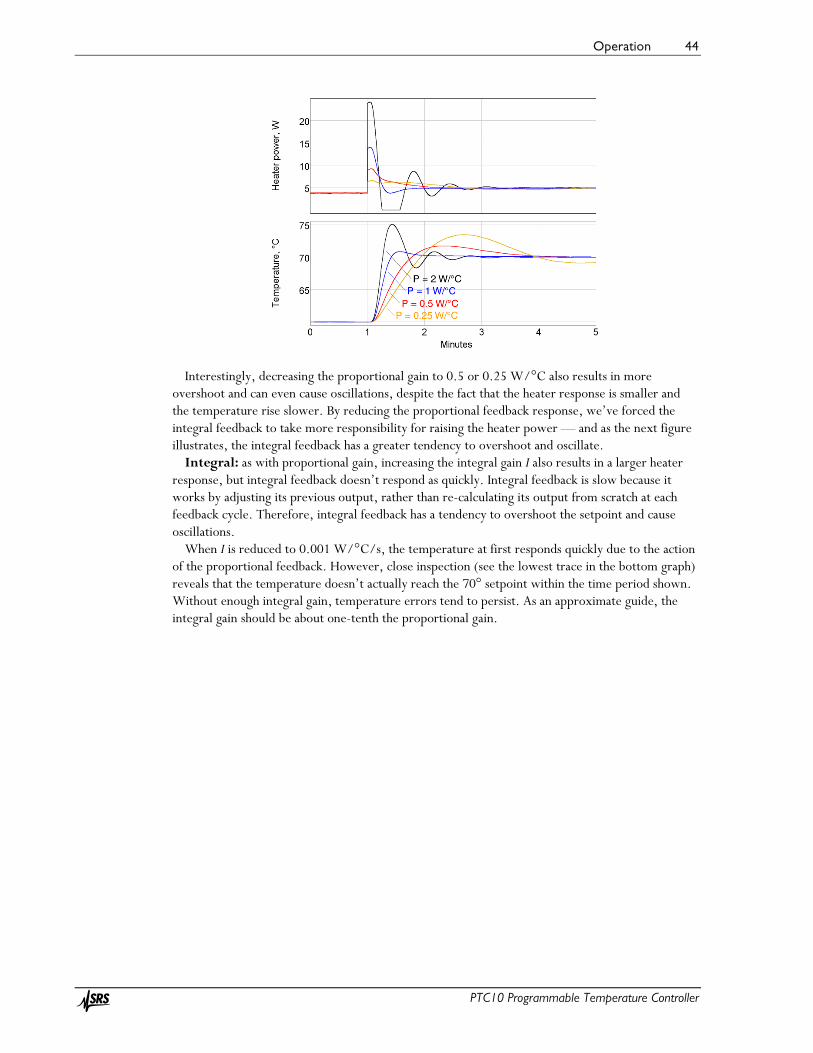
Operation 44
PTC10 Programmable Temperature Controller
Interestingly, decreasing the proportional gain to 0.5 or 0.25 W/°C also results in more overshoot and can even cause oscillations, despite the fact that the heater response is smaller and the temperature rise slower. By reducing the proportional feedback response, we’ve forced the integral feedback to take more responsibility for raising the heater power — and as the next figure illustrates, the integral feedback has a greater tendency to overshoot and oscillate.
Integral: as with proportional gain, increasing the integral gain I also results in a larger heater response, but integral feedback doesn’t respond as quickly. Integral feedback is slow because it works by adjusting its previous output, rather than re-calculating its output from scratch at each feedback cycle. Therefore, integral feedback has a tendency to overshoot the setpoint and cause oscillations.
When I is reduced to 0.001 W/°C/s, the temperature at first responds quickly due to the action of the proportional feedback. However, close inspection (see the lowest trace in the bottom graph) reveals that the temperature doesn’t actually reach the 70° setpoint within the time period shown. Without enough integral gain, temperature errors tend to persist. As an approximate guide, the integral gain should be about one-tenth the proportional gain.

Operation 45
PTC10 Programmable Temperature Controller
Derivative: derivative feedback reduces the heater output whenever the temperature is rising rapidly. In the example below, when the derivative gain D is increased from 3 to 6 W·s/°C, the amount of overshoot and oscillation decreases. The temperature rise is also a little slower, but because there is less oscillation the system stabilizes at 70°C sooner.
However, if the derivative gain is too large, it too can produce oscillations — because when the temperature is rising rapidly, derivative feedback reduces the heater output, which causes the temperature to rise more slowly, which makes the derivative feedback increase the heater output, and so on.

Operation 46
PTC10 Programmable Temperature Controller
With the right amount of derivative feedback, we can increase P and I to levels that would otherwise cause oscillations, and thereby obtain faster, more responsive feedback control.
Automatic tuning algorithms
During automatic tuning, the PTC10 changes the heater power, measures how much and how quickly the temperature changes in response, and then estimates the optimum values of the gain factors P, I, and D. Two tuning algorithms are available on the PTC10: the relay tuner and the step response tuner.
Relay tuner
Heater power (top) and sensor temperature (bottom) during relay autotuning. Step Y is 1 W, Lag is 30 s, feedback is initially on, and the
system starts with the temperature stabilized at the 50°setpoint. After the tuning has finished, the feedback turns on and re-stabilizes the system at
50°C after a few cycles of oscillation.
The relay tuner creates a temperature oscillation by switching the heater between two output values:
Outputhigh = OutputI + (Step Y)/2 Outputlow = OutputI – (Step Y)/2
where OutputI is the initial output and Step Y is the value specified in the “Step Y” control. Note that the relay tuner cannot be started unless the output is greater than (Step Y)/2. For best results, the output should be greater than Step Y.
The relay tuner begins by disabling the feedback (if the feedback was on) and measuring the drift and noise of the feedback input signal in the absence of any changes to the feedback output. The drift-and-noise measurement continues for one-third the amount of time specified with the “Lag” control; the resulting drift-and-noise value is the difference between the largest and smallest input signal observed during this time.
After the drift and noise measurement, the relay tuner sets the heater output to Outputlow for the Lag time to start the oscillation. If during this period the feedback input does not change by at least ten times the drift-and-noise value, an error message is displayed in the Status window and tuning is

Operation 47
PTC10 Programmable Temperature Controller
cancelled. If this occurs, either 1) ensure that the temperature is stable before starting the step response; 2) increase step Y; or 3) if it looks like the temperature didn’t have enough time to respond, increase the Lag time.
The tuner then sets the output to the Outputhigh value. Then, each time the temperature crosses its initial value (50 °C in the figure above), the output is switched from high to low or low to high. This produces a temperature oscillation 180° out of phase with the output oscillation. The tuner performs two oscillation cycles, not including the kick start, and measures the period and amplitude of the second oscillation.
The relay tuner has to wait several times for the temperature to cross its initial value. If the temperature measurement is disturbed during this time (for example, if the temperature sensor is moved, or if the sensor is in an oven and the oven door is opened), the temperature may never cross its initial value and the tuner may run indefinitely without finishing.
Step response tuner
Heater power (top) and sensor temperature (bottom) during step response autotuning. Step Y is 2.5 W, Lag is 45 s, feedback is initially off, and the system starts at room temperature. After the step response is complete,
the feedback turns on and the temperature drops before stabilizing at the 50°C setpoint.
The step response tuner makes a single change to the amount of power delivered to the heater, and measures how much and how quickly the temperature changes in response.
The step response tuner begins by disabling the feedback (if the feedback was on), and measuring the drift and noise of the feedback input in the absence of any changes to the output. The drift-and-noise measurement takes one-third the period specified with the “Lag” control; the resulting drift-and-noise value is the difference between the largest and smallest input signal during this time.
Next, the step response tuner increases the output by the value specified with the “Step Y” control. The tuner then waits for the amount of time specified with the “Lag” control. If during this period the feedback input does not change by at least ten times the drift-and-noise value, an error message is displayed in the “Status” window and tuning is cancelled. If this occurs, either 1) ensure that the temperature is stable before starting the step response; or 2) increase step Y; or 3) if it looks like the temperature didn’t have enough time to respond, increase the Lag time.
The tuner continuously measures how quickly the feedback input changes, (i.e., the slope of the feedback input with respect to time). Tuning ends once the lag period has passed and the most

Operation 48
PTC10 Programmable Temperature Controller
recent slope is less than half the largest slope. The tuner then calculates the maximum slope, the lag time, and the total response, and uses these values to calculate the PID gains.
Because the slope calculation is sensitive to noise, it’s important to enable the “lopass” filter on the feedback input channel to achieve accurate tuning results. Since the relay tuner does not require a slope measurement, it’s less sensitive to noise than the step response tuner.
If the tuning mode is set to “Auto”, the PTC10 selects the relay tuner if both its high and low outputs are within the heater’s limits; otherwise, it selects the step response tuner. For example, if the output is off (and can’t go negative) when autotuning is started, the step response tuner runs because the relay tuner would require a negative output.
Aggressive, moderate, and conservative tuning Both the step response and relay tuners offer aggressive, moderate, and conservative tuning
options. Conservative tuning theoretically produces zero overshoot and is usually the best choice when the temperature needs to follow a changing setpoint. The aggressive tuning option theoretically produces 25% overshoot (although in fact it tends to be larger) and is usually the best choice for applications in which the setpoint is constant. Moderate tuning produces a very stable feedback loop that behaves reasonably in a wide variety of situations.
The figure below compares the system’s behavior when we change the setpoint from 60 to 70°C after relay tuning with the aggressive, moderate, and conservative options. In this case, conservative tuning produces the best response.
However, the results are much different if we look at how the system responds to a thermal disturbance. The next figure shows how well the system recovers when we start blowing air over the heater with a fan. The setpoint is a constant 60°C. In this case, aggressive tuning produces the best response.

Operation 49
PTC10 Programmable Temperature Controller
The actual behavior of your system might vary significantly from the behavior shown in these figures. In any event, the feedback gains determined by the automatic tuning algorithms should generally be regarded as only a starting point. In critical applications, the gains normally need to be manually adjusted to achieve good feedback performance.
Using the automatic tuner
Start with a stable temperature. Before the autotuner is started, the temperature must be stable. If the system hasn’t been tuned before, the easiest way to get a stable temperature is to let the system sit undisturbed for a long period of time with the heater off. On the other hand, if the PID gains have been set before and just need to be re-optimized, it may be easier to turn the feedback loop on and let the feedback stabilize the temperature. The autotuner can be started with the feedback either on or off.
Disable or enable derivative feedback. Because derivative feedback can amplify sensor noise, it may sometimes be preferable to disable it. If the derivative feedback gain is set to zero before autotuning begins, derivative feedback is disabled and the autotuner calculates P and I feedback gains, leaving the derivative feedback set to zero. In contrast, if the derivative feedback gain is initially nonzero, the autotuner calculates P, I, and D feedback gains using a more aggressive algorithm. Therefore, setting D to a nonzero value (the exact value doesn’t matter) before autotuning produces faster-acting feedback but more noise. If your temperature sensor is noisy or you’re not using a lowpass filter, leave D set to zero.
Set the step size and lag time. “Step Y” controls how much the PTC10 increases the heater output, and “Lag” controls how long the PTC10 waits for a response. If either value is too small, the PTC10 may, after attempting to tune, display a message saying that there was an insufficient response. If the values are too large, tuning will take longer than necessary and your heater will get excessively hot.
Start tuning. To begin tuning, go to the channel setup screen and set the tuning mode to “Auto”.
If the tuner finishes successfully, a high-pitched tone plays and the feedback loop starts running. If the tuner was unsuccessful (because Output Enable was off, the heater was unplugged, the temperature sensor was unplugged, the heater was out of range, or the response was too small), a low-pitched tone plays and the feedback loop is turned off.
When PID tuning is started, a window with information about the autotuner’s progress appears. This window can be dismissed by touching the “OK” button or any menu key. Dismissing the

Operation 50
PTC10 Programmable Temperature Controller
window does not cancel autotuning; to cancel autotuning, either 1) set the tuning Mode to “Off”; 2) touch the output channel’s “Off” button; or 3) disable all outputs by pressing the “Output Enable” key.
If the status window is dismissed, it can be displayed again by touching the “Status” button in the output’s “Channel” menu.
Explanation of error messages produced by the autotuner One of the following messages appears in the Tuning Status window if tuning was unsuccessful. If
tuning fails and you don’t see a message, press the Channel > Tune > Status button.
Tuning was cancelled because the response was less than 10 times the noise and drift This message indicates that the heater produced an insufficient temperature response. It can
result from any of the following factors:
• The temperature was not stable before the autotuner was started, or the temperature was changed by some external factor after the autotuner was started. In particular, after running the autotuner, it’s necessary to wait for the temperature to re-stabilize before running the autotuner again.
• The autotuner disturbance size (Step Y) was not large enough to create a noticeable change in the temperature.
• The autotuner wait time (Lag) was not long enough for the heater to change the temperature.
To determine the source of the problem, look at a dual plot with the heater output on one plot and the sensor temperature on the other. Make sure that the temperature was stable before the heater turned on and that it changed significantly after the heater was turned on.
Autotuning was cancelled because the Tune->Mode control was set to "Off" This message indicates that the user turned off autotuning (by setting the autotuning mode to
“off”) while it was running.
Autotuning was cancelled because the PID mode was set to manual. The user turned off PID feedback while the tuner is running. The tuner is unable to run when
PID feedback is turned off.
Autotuning was cancelled because the PID mode was set to \"follow\" The user changed the PID mode to “Follow”. The tuner is unable to run in this mode.
Tuning was cancelled because the input was disconnected No sensor signal was detected. Ensure that a sensor is plugged in and that its reading is not blank.
If the reading is blank, an incorrect sensor range, sensor type, or calibration may be selected.
Unable to tune feedback because the outputs are disabled. Press the Output Enable button to enable outputs. The outputs must be enabled before autotuning, or else the PTC10 will not be able to provide
any power to the heaters.
Operation 51
PTC10 Programmable Temperature Controller
Unable to tune feedback because the heater is disconnected This message appears when the heater is connected to channels Out 1 or Out 2 and the measured
heater resistance is less than 1 ohm or greater than 10,000 ohms.
Unable to tune feedback due to a hardware fault in the heater output This message appears when the heater is connected to channels Out 1 or Out 2 and the current at
the + and – terminals is not equal, or current was detected when the heater was supposed to be off, or the measured current differs from the expected current. Make sure that the heater is not shorted to ground or to another power supply.
Unable to tune feedback because the heater is under range Unable to tune feedback because the heater is over range
If Step tuning is selected, the heater output must be less than the maximum output minus Step Y. If Relay tuning is selected, the heater output must be less than the maximum output minus Step Y/, and greater than the minimum output plus Step Y/2.
Suggestions for best tuning results
• While tuning, use the “Plot” display to graph the heater output and the temperature on separate graphs. Make sure that you can see the temperature begin to rise or fall after the heater output changes.
• If tuning fails, let the temperature stabilize and try increasing the step Y or lag before attempting to tune again. You may also need to increase the lowpass filter time constant.
• The temperature must be stable when tuning is started. Either the feedback must be running and stabilized at the setpoint, or the heater must be off and the temperature stabilized at the ambient temperature.
• Set the lowpass filter on the input (temperature) channel to a value just below the expected response time of the system. The step response tuner in particular requires adequate lowpass filtering to produce accurate results.
• Make sure the system doesn’t experience any temperature disturbances during the tuning process.
• Since the ideal feedback parameters usually vary with temperature, run the tuning algorithm at about the temperature at which the feedback will be used. If the system has never been tuned before you may need to tune at room temperature, then let the feedback bring the system to its working temperature, and re-tune at the working temperature.
• The autotuning algorithm assumes that the temperature is a linear function of heater power. In most cases it isn’t, which means that the results produced by the algorithm may not be perfectly accurate and may need to be manually adjusted.

Operation 52
PTC10 Programmable Temperature Controller
Front-panel controls The front panel has six menu keys to the left of the display labeled “Select”, “Numeric”, etc.
These keys can be pressed at any time to display one of the six main screens. Each of the main screens except for the Program screen has six columns of buttons, usually with a column name at the top of each column. Each button has a name in large text and, usually, a value beneath the name in smaller text.
In this manual, buttons are referred to by the name of the screen (Select, Numeric, Plot, etc.), the name of the column (if any), and the name of the button, separated by dots. For example, “System.Log.Interval” refers to the Interval button in the Log column of the System screen. The text “System.Log.Interval” can also be sent to the PTC10 over one of its communications ports (RS-232, USB, etc.) as a remote command.
The front panel also has a “Help” button that displays help text for whatever is currently on-screen, and an “Output Enable” button that turns all the PTC10’s outputs on and off.
USB logging indicator
If a USB memory stick is plugged into the PTC10, a small dark-red circle appears in the upper-right corner of the screen. Touch the circle to turn USB logging on; the circle will turn light red to indicate that data is being logged to USB. Touch the circle again to turn USB logging off.
Removing the USB memory device or powering down the PTC10 without first ejecting the device causes loss of data and corruption of the memory device. A corrupted device should be repaired by plugging it into a PC and running a program such as chkdsk (Windows) or fsck (Linux).
“Help” key
The “Help” key displays a popup screen that provides more information about whichever window is currently visible. For example, to get a description of the “Value” setting in the “Channel” menu, first touch the “Channel” key to bring up the Channel screen, then touch the “Value” button to bring up the Value input window, and then press the “Help” key. The “Help” key does not work with pop-up windows that just display text and don’t provide any opportunity for changing a value, like the “Output Enable” window that appears when you press the “Output Enable” key.
“Output Enable” key
When the PTC is turned on, all outputs are disabled (however, inputs function normally). This safety feature gives you a chance to adjust the PTC’s settings before it begins to provide power to the heaters. To turn on the outputs, press the “Output Enable” key twice. A red light next to the “Output Enable” key turns on to indicate that the outputs are active, and any PID feedback loops that were previously running begin to provide power to the heaters.
If the outputs are enabled, pressing the “Output Enable” key once disables all outputs, setting them to zero. Inputs continue to function normally. In an emergency situation, the Output Enable key is the quickest way to turn off the PTC’s outputs. Re-enabling the outputs immediately returns all outputs to their previous values.
In certain cases it may be desirable to have the PTC power up with the outputs enabled to ensure that feedback loops automatically resume after a power failure. This can be accomplished with a startup macro (see the “Startup macros” section).

Operation 53
PTC10 Programmable Temperature Controller
The Output Enable key is not intended to prevent electric shocks. When handling exposed heater wires, always disconnect the wires from the PTC10 or unplug the PTC10 from the wall.
Press and hold the "Output Enable" key for 3 seconds to put the PTC10 into standby mode. In standby mode, the outputs are turned off, data acquisition and macros are paused, the front panel display and system fan are shut off, and the system does not respond to remote commands. RTD excitation currents are still on, and an internal cooling fan may switch on occasionally. Press the "Output Enable" key again to leave standby mode.
“Select” screen
Each column of buttons on this screen represents one I/O card, and each button shows the name and the current value of an I/O channel. The value may not appear if no sensor or heater is connected to the channel.
The PTC10 includes two I/O cards as standard equipment: a 4-channel, ±10V analog I/O (AIO) card in slot 5, and a digital I/O (DIO) card in slot 6. These cards appear in the two right-most columns of the Select screen. The remaining four columns show any optional I/O cards that have been installed.
Buttons turn red if the channel’s alarm is triggered; that is, if the alarm is enabled and the reading is outside of the alarm limits or no sensor is connected. The name of the channel appears in bold if the channel uses a custom calibration table.
Touch one or more buttons to select which channels you’d like to view on the Numeric, Plot, and Channel screens. The top of the Select screen has four Group tabs that let you save and recall up to four groups of selected channels. Touch one of the tabs or repeatedly press the “Select” button to change the selection group.

Operation 54
PTC10 Programmable Temperature Controller
“Numeric” screen
This screen displays the current values of the selected channels as numbers. The more channels that are selected, the smaller the displays are. If enough space is available, an annunciator may appear that indicates whether the sensor or heater is disconnected (“N/A”), over range (“Hi”), under range (“Lo”), if outputs are disabled (“Off”), or if an internal error has occurred (“Err”).
Input displays turn red whenever the input’s alarm is triggered. The name of the channel appears in bold if the channel uses a custom calibration table.
Repeatedly press the “Numeric” button to cycle through the four selection groups. Touch one of the channel displays to show setup menu for the channel.
“Plot” screen
This screen shows logged data from the selected channels on one or more graphs. Press the Plot key repeatedly to cycle between the four formats described below (single, multi, custom, and ponytail).
The Plot screen always shows logged data. If, for example, the log interval is set to 10 s, the graph will have a “stairstep” appearance with a step every 10 seconds.

Operation 55
PTC10 Programmable Temperature Controller
Touch the tabs at the top of the screen to change the selection group. Each of the four groups remembers its graph format (single, multi, etc.), X range, and Y range. Therefore, when you change the selection group, the graph’s range may also change.
Single plot Up to eight selected channels are shown together on one graph with a single Y axis. If more than
eight channels are selected, only the first eight are shown.
Single plot mode showing the ambient temperature measured by two thermocouples (channels 3B and 3C) and one Pt100 RTD (4B). RTDs
have a much lower noise level than thermocouples.
Multi plot Each channel is shown in its own graph with an independent Y axis. If more than eight channels
are selected, only the first eight are shown.
In multi plot mode, each sensor gets its own graph. The X scale is the same for all 3 graphs, but the Y scale is different.

Operation 56
PTC10 Programmable Temperature Controller
Custom plot Each channel is assigned to a plot according to its Channel.Plot setting.
In custom plot mode, the user can manually assign each channel to a graph. Here the thermocouple inputs have been assigned to plot 1 and the
RTD input to plot 2.
Ponytail plot Like Single plot, up to eight selected channels are shown together on one graph. Each trace is
offset by its initial value so that the trace begins at zero. The offset is recalculated whenever you touch the graph to zoom or pan, or whenever you switch to another screen and back to the Plot screen. If you don’t touch the PTC’s controls, the offset is never recalculated.
Using the ponytail plot does not affect how channel values are logged; the offsets are only applied to the plots, not to the log files.
In ponytail plot mode, all traces are offset so that they start at zero.

Operation 57
PTC10 Programmable Temperature Controller
Zooming and panning
To change the X axis scale of a plot, touch anywhere inside the plot:
• Touch the right half of the plot to zoom in • Touch the left half to zoom out • Drag to pan.
Whenever the most recent data is visible on the graph, the graph automatically scrolls to keep the most recent data visible. If the most recent data is not visible, the words “X lock” appear in the bottom-left corner of the screen to indicate that scrolling is disabled. To show current data and resume scrolling, touch the words “X lock”.
Graphs that appear together on a screen always have the same X axis range. However, each selection group has its own, independent X axis range.
How to change the X axis scale
How to pan the graph horizontally

Operation 58
PTC10 Programmable Temperature Controller
By default, the PTC10 continually adjusts the Y-axis scale to accommodate all the data on the graph. Each graph has its own, independent Y axis scale. To change the Y axis scale for a particular graph, touch the area to the left of its Y axis.
• Touch the top third of the Y axis to zoom out. Automatic scaling is disabled, so the Y axis scale no longer changes as new data is acquired.
• Touch the middle third to 1) re-enable automatic scaling and 2) reset automatic scaling, that is, ignore previously-acquired data and adjust the Y range to accommodate only new data.
• Touch the bottom third to zoom in. Automatic scaling is disabled. • Drag to pan.
How to change the Y scale of the bottom graph
How to pan the bottom graph vertically

Operation 59
PTC10 Programmable Temperature Controller
“Program” screen
A program is a set of one or more instructions that can be used to customize the behavior of the instrument. Programs can be input over the RS-232, GPIB, USB, or Ethernet interface, from the program screen, or as a files on a USB memory device. Regardless of how a program was input, its progress can be monitored from the program screen.
The Program screen has an Input window, which shows text received over RS-232 or GPIB; a Messages window, which shows responses and error messages from the PTC10; and a Progress window, which shows the list of instructions that make up the current program.
If a program is not running, you can compose or modify a program by touching a line in the Progress window. Touching a blank line brings up a list of possible commands. Touching a line that already contains an instruction brings up a list of three options: you can add a new instruction on the line above the one that was touched; delete the instruction that was touched; or replace the instruction that was touched.
The Program screen has six buttons:
Play symbol If a program is displayed but not running, press this button to start the program. If a program is
running in the currently-selected tab, the button is highlighted and pressing it stops the program.
Pause symbol Press this button to temporarily pause the program running in the currently-selected tab. Press
the button again to resume running the program.
Clear Erases all text from the Input, Messages, and Progress windows. Unless it has previously been
saved, the current program is lost. This button cannot be pressed while a program is running in the current tab.
Load Touch this button and a list of programs stored in memory is displayed. Programs can be stored
in memory with the Program.Save button, by sending a “define” instruction to a remote interface, or by attaching a USB device with text files contained in a “Macros” folder. Select a program from the list and its component instructions are displayed in the Progress window, replacing whatever was previously in the window.

Operation 60
PTC10 Programmable Temperature Controller
The Program.Load button can be used to edit a previously-saved program: load the program, then edit it in the Progress window, and finally re-save the program with the Save button.
To call a previously-saved program as a subroutine from a program that you’re composing, don’t use the Program.Load button, since it would erase the rest of the program. Instead, touch the “Progress” window and select the saved program from the list of commands. The Program.Load button cannot be pressed while a program is running in the current tab.
Save Saves the current program, as shown in the Input window, to memory. You’ll be asked to supply
a name for the program. Up to 15 programs can be saved. If 15 programs are already saved, the Save button will have no effect.
Saved programs can be run using the “Load” button or called as subroutines by touching a line in the “Progress” window. Saved programs can also be called by sending their name (like any other instruction) over one of the remote interfaces.
Delete Touch this button to display a list of programs stored in memory. Select a program from the list
and it will be deleted from memory. The Program.Delete button does not affect the status of currently-running macros.
Sending programs over RS-232, USB, GPIB, or Ethernet
Programs can be entered from a remote interface such as RS-232, USB, Ethernet, or the optional GPIB port. Each line of text sent to the PTC10 is run as a separate program (the entire program must be on a single line). If two or more lines are sent to the PTC10 in quick succession, the programs may run concurrently; that is, the PTC10 does not finish running the first program before beginning the second. However, the first program sent will always begin running before the second program. If it’s preferable to run programs sequentially, begin each line with the *PHO instruction.
See the “remote interface” section of this manual for more details.
Preparing programs as files on USB memory devices
The PTC10 can also read programs that are stored as text files in a USB memory device. This is the best way to enter longer programs.
Create a “Programs” folder in the root directory of the memory device. Type the program in a word processor or text editor, and save it as a .txt file in the “Programs” folder. Plug the memory device into the PTC10. To verify that the program is available, look for its name in the Macros column of the System Setup screen. The program can be run just as if it were saved in the PTC10’s memory; however, after the USB device is unplugged, the program can no longer be started.
While the PTC10 is running you can unplug the USB device, use a PC to edit a program stored on the device, plug the USB device back into the PTC10, and run the new version of the program. To ensure that the PTC10 runs the new version of the program, use the Program screen’s Load button to re-load the program.
Program files can contain up to 16384 characters, and may include multiple lines and comments (an apostrophe, i.e. a single quote mark, indicates that the rest of the line is a comment). Except for the first newline after a comment, all whitespace is ignored; each line can be empty or can contain one or more instructions.

Operation 61
PTC10 Programmable Temperature Controller
Preparing programs from the front panel
Simple programs, such as a series of temperature ramps, can be entered from the front panel. To enter a program from the front panel, press the “program” button and then touch the
Progress window. A list of available top-level commands appears.
Any button with a name ending in a dot brings up a sub-menu when pressed. For example, the commands to change the feedback setpoint or alarm limits for a channel are accessed by first touching the “channel” button.
Touch the left square bracket (the button in the upper-left corner). Square brackets surround blocks of code to be repeated. You’re returned to the “Program” screen, where the first line in the “Progress” window is now a left square bracket.
Touch the Progress window again, anywhere beneath the first line. The list of possible instructions appears. Select “program.” from the list. Touching this button brings up a list of instructions that affect the program. For example, “cls” clears the Messages window; “name” assigns a name to the program; and “kill” ends a named program.

Operation 62
PTC10 Programmable Temperature Controller
Select “print”. An alphanumeric input screen appears where you can enter an argument for the “program.print” instruction. Type “hello”.
Touch the OK button. You are returned to the Program screen and the instruction “program.print “hello”” appears in the second line of the Progress window.

Operation 63
PTC10 Programmable Temperature Controller
Now enter the instruction: “program.pause 1 s”. The pause instruction has two arguments that must be entered separately. First you’ll be shown a numeric input screen where you can type “1”. Touch “OK” and you’ll get a second menu where you can enter the units (“s”). The completed instruction will pause the program for one second.
Next, enter the instruction “program.print world” followed by “program.pause 1 s”. Finally, enter the instruction “] 3”. This makes the program repeat everything between the square brackets three times.
Press the start button. While the program is running, the current instruction is highlighted and the total number of repetitions as well as the number of repetitions remaining appears next to the right square bracket. In addition, while the program is running a new tab (labeled “New program”) appears at the top of the screen. By touching this tab, you can enter and start a second program while the first program is still running.
When the program is done, the messages “hello” and “world” should appear three times in the Messages window.
Once the program is finished you can press the start button to run the program again, the “Save” button to save the program, or the “Clear” button to erase the program and the Messages window.
Running concurrent macros
Since a macro can run for a long period of time or even indefinitely, it’s possible to start a new macro before the previous macro has finished. It’s also possible to run multiple instances of a saved macro simultaneously.
The PTC can run at most ten concurrent macros (including the startup macro, macros received over all I/O ports, and macros started from the Program screen). If an eleventh macro is started, a “Too many macros” message appears and the macro does not run.
If the PTC10 is turned off and turned back on again, macros that were running when the PTC10 was turned off are not restarted.

Operation 64
PTC10 Programmable Temperature Controller
“Channel” screen
The “Channel” screen includes controls for all settings that affect individual data channels. Sensor calibration, PID feedback parameters, and alarms are all set up through this screen. Note that the layout of the screen varies depending on which channel is selected; for example, only output channels have PID controls, while only input channels have alarm controls.
Only one channel can be set up at a time. One tab appears at the top of the screen for each channel in the current selection group; select the tab for the channel you want to set up. Repeatedly pressing the “Channel” button cycles through the four selection groups.
Name Sets the name of the channel. The name must have 10 or fewer characters.
Value If the channel is an input, this button shows the most recent reading but is grayed out, indicating
that the reading can’t be changed from the front panel. If the channel is an output, the reading is not grayed out and pressing this button allows you to enter a new output value. However, if PID feedback is turned on or Output Enable is off, changing the value will have no effect.
Off Sets the PID feedback mode to Off, cancels any PID tuning processes currently operating on the
channel, and sets the channel’s output to zero or the “Low lmt” value, whichever is higher. This button is only available for output channels.
Low lmt This control, which is only available for output channels, sets the minimum output. However, if
the minimum is greater than zero, the output is still set to zero whenever outputs are disabled with the “Output Enable” key. Limits are always expressed in the same units as the value. The limits should normally be changed when the output units are changed, since the limits are not automatically converted to the new units.
Hi lmt This control, which is only available for output channels, sets a maximum limit on the output.
It’s typically used to prevent the PID feedback loop from delivering excessive power to a heater. If the high limit is less than the low limit, the low limit takes precedence.

Operation 65
PTC10 Programmable Temperature Controller
Range If the I/O card has more than one range, pressing this button displays a menu of available ranges.
If the card only has a single range, this button is grayed out.
IO type Each output channel has an ADC that can measure the actual output. The “IO type” button
determines whether the output that you see on the screen is the value measured by the ADC (“Meas out”) or the value requested by the user or the PID feedback loop (“Set out”).
The PTC’s general-purpose analog and digital I/O channels are bidirectional, i.e. they can be used to monitor external signals, or to produce signals. In these cases, the IO type button has three settings: “Set out” means that the channel outputs a voltage and the value you see on-screen is the value you asked for. “Meas out” means that the channel outputs a voltage and the value you see on-screen is the value measured by the ADC. “Input” means that you can drive the channel with an external voltage, and the channel will measure that voltage.
Plot Indicates which plot the channel will appear in when the “Plot” screen is showing, the plot type is
Custom (see the “Plot Screen” section above), and the channel is selected on the “Select” screen. Choose one of eight plots for the channel to appear in, where plot 1 is the uppermost plot. If no channels are assigned to a given plot, the plot won’t appear on the “Plot” screen. For example, if all selected channels are assigned to plot 4, only one plot appears on the Custom plot screen.
Logging By default, each channel’s value is written to the log once every second. This global log rate can
be changed on the “System” screen (System.Log.Interval). The Logging button makes it possible to override the global log rate for individual channels.
Figures Sets the maximum number of digits that are shown after the decimal point for all channel values.
Fewer digits may be shown if the value wouldn’t otherwise fit into the available space. This setting does not affect logged data, PID feedback, or plots.
If the value is set to “Default”, the number of figures is controlled by the global Figures setting on the System screen.
Cycle (AC output card only) The PTC420 has a solid-state relay that can either deliver full power or no power to the heater.
To more precisely control the power delivered to the heater, power is switched on for some fraction of a preset cycle time, then switched off for the remainder of the cycle. For example, if the cycle time is 10 seconds, the relay might switch on at time t = 0 s, off at t = 1 s, on at 10 s, off at 11 s, on at 20 s, and so on. This would produce 10% of the maximum output.
The Cycle instruction sets the on/off cycle time. Shortening the cycle period will reduce temperature swings associated with switching the current on and off, but will also reduce the lifetime of the relay. The cycle time must be between 1 and 240 seconds inclusive.
Dither (DC output card only) The DC output card has a 16 bit DAC. For greater resolution, the least significant bit can be
dithered. Dithering is enabled by default.

Operation 66
PTC10 Programmable Temperature Controller
Current (4-channel RTD reader and 1-channel thermistor/diode/RTD reader only) Controls the direction of the sensor excitation current. Reverse the current to detect offsets due
to parasitic thermocouple EMFs or 60 Hz noise. In AC mode, these offsets are automatically removed by reversing the current at each ADC reading; each reported temperature is based on the average of the last two ADC readings (cutting measurement bandwidth in half). The PTC320 thermistor/diode/RTD reader’s excitation current can be turned off entirely with this control.
Current (TEC driver card only) Controls the amount of excitation current (1 mA, 100 µA, 10 µA, or auto) provided to the
temperature sensor. The sensor excitation current on the TEC driver card cannot be reversed. The table below shows the excitation current produced by the “auto” current setting on the
PTC440 TEC driver when a resistive sensor is in use. The sensor resistance is continuously monitored and the excitation current is adjusted whenever the sensor resistance rises above or drops below the levels shown in the table. The “auto” current setting always produces 1 mA when an LM335 or AD590 sensor is in use.
Sensor
resistance Excitation
current <2 kΩ 1 mA 1– 20 kΩ 100 µA >10 kΩ 10 µA
Excitation current produced by the “auto” current setting on the PTC440 TEC driver (for resistive sensors only)
The overlap of the resistance ranges keeps the PTC440 from rapidly switching back and forth between two excitation currents. If, for example, the sensor resistance is between 1 and 2 kΩ, the PTC440 can select either 1 mA or 100 µA excitation, and if possible, it keeps the excitation at its previous value.
Slew (Only appears on the “Out” channel of TEC driver cards) Sets the maximum positive and negative rate of change of the TEC driver output. The rate must
be between 0 and 1000 amps per second, and the default value is 100 amps per second (which corresponds to an unlimited slew rate at 10 samples/second). Each time the TEC current is set (either by a PID feedback loop or with the Channel.value control), it ramps to the new value at this slew rate.
Rapid changes in the TEC current can create electromagnetic interference (EMI) in the temperature sensor and any other sensors near the TEC. The resulting spikes in the temperature reading can cause feedback oscillations or noisy temperature readings.
For the slew rate setting to be effective, the A/D rate (set with the System.Other.A/D rate control) should less than or equal to 100 ms. The slew rate is implemented with a software algorithm that runs at each A/D conversion, and the TEC driver output has a 13 Hz lowpass filter. If the A/D rate is set (for example) to 1000 ms, the algorithm only changes the TEC output current once each second and the output current therefore changes in discrete steps, each of which may exceed the desired slew rate.
When outputs are disabled by pressing the Output Enable button or with the “OutputEnable off” remote command, the TEC output turns off immediately, regardless of the slew rate setting. When outputs are re-enabled, the TEC output ramps up to its previous value at the desired slew rate.

Operation 67
PTC10 Programmable Temperature Controller
Vmax (Only appears on the “Vmon” channel of TEC driver cards) Sets the maximum voltage that the PTC440 TEC driver can output. This control is intended to
protect thermoelectric coolers from damaging voltages. If the measured voltage across the TEC is above Vmax for more than one second, current to the TEC is automatically shut off. The first time this occurs after the system is turned on, a “hardware fault” window also pops up on the front-panel display. To turn the current back on again, set the channel’s output to zero (for example, by touching the “Off” button on the Channel menu, or by disabling and re-enabling all outputs with the Output Enable button).
If the output current suddenly increases and the slew rate setting is too high, it is still possible to damage the TEC even if Vmax is set to an appropriate value. To prevent such damage, the output voltage should, if possible, also be limited by setting the output range to the lowest possible value (e.g., 3V 5A, 6V 5A, or 9V 5A); and by setting the “Lo lmt” and “Hi lmt” controls for the output channel to current values that do not produce excessive voltages.
The TEC voltage can also be limited using the Vmon channel’s alarm. Set the Channel.Alarm.Mode control to “level”, the Channel.Alarm.Latch control to “yes”, and the min and max to the desired voltage limits. Touch the Channel.Alarm.Output button and select the TEC output channel. The Channel.Alarm.Lag control can be set to 1 s to prevent noise spikes from inadvertently triggering the alarm, or left at 0 s to better protect the TEC from rapid voltage increases.
PCB (RTD, thermistor, and thermocouple readers only) Sets the maximum printed circuit board (PCB) temperature for all channels on the selected card.
If the card’s temperature exceeds the maximum and System.Other.Fan is set to “Auto”, the PTC10 increases the fan speed to reduce the card’s temperature. The PCB control only appears for I/O cards that have internal temperature sensors.
The PCB temperature is always in °C, regardless of the System.Display.Units setting. The default setting is 30°C.
Thermal drift of the RTD or thermocouple inputs can be reduced by setting the PCB temperature of one card to a lower value. This value should be a few degrees above room temperature, (i.e., 25°C). Reducing the maximum PCB temperature results in tighter regulation of the PTC10’s internal temperature, particularly of the selected card, at the expense of more fan noise.
However, if a DC output card is being used the system might sometimes turn up the fan speed to prevent thermal damage to the output card, causing larger internal temperature variations.
Diff (input channels only) The value of the channel selected with the “Diff” button is continuously subtracted from
whichever channel is selected in the tab bar at the top of the “Channel” menu. To turn the difference feature off, touch “Diff”, then touch whatever channel is currently selected. The “Diff” button then shows an empty value.
Channels with a difference filter can be used as the input for PID feedback loops, in which case the feedback maintains a constant temperature differential between two locations, rather than a constant absolute temperature.
Lopass (input channels only) If a non-zero value is selected, a 6th-order RC lowpass filter is applied to the selected channel.
The lowpass filter removes noise with a period shorter than the indicated time constant but also increases the effective response time of a sensor.
The lowpass filter should always be enabled on the temperature inputs of all PID control loops. This is especially true when using step response PID tuning or when derivative feedback is enabled

Operation 68
PTC10 Programmable Temperature Controller
(i.e., the derivative gain is nonzero), since these algorithms calculate the change in temperature over time and therefore produce poor results if high-frequency noise is present. The filter’s time constant should be just below the response time of the system. When using an AC output card for PID control, the filter constant should be longer than the cycle time of the output.
When a sensor is disconnected and then reconnected to a lowpass-filtered channel, the PTC allows one second for the reading to settle. During this time, no reading appears. The output of the lowpass filter is then set equal to the next ADC reading so that you don’t have to wait for the reading to gradually settle to its new value.
Units (PTC420 AC output card and PTC430 DC output card only) By default, the output of these heater driver cards is measured in watts. Using the “Units” button,
the output units of the AC output card can be changed to “%” (i.e., percentage of the maximum output) and the output units of the DC output card can be changed to “A” (heater current) or “V” (heater voltage).
d/dt (input channels only) Derivative. If this control is set to “On”, the value of the channel is replaced with its derivative
with respect to time. Since the derivative is normally somewhat noisy, the lowpass filter should be enabled when the derivative filter is used.
Follow (virtual input channels only) This button only appears for virtual channels that are configured as inputs. Once a channel is
selected, the virtual channel’s value continuously follows the value of the selected channel. Difference, derivative, or other filters may be applied to the virtual channel to modify the value. For example, select “Follow”; then, on the menu that appears, touch the button for channel 3A (assuming that channel 3A exists). The virtual channel now echoes the value of channel 3A. Next select “Diff” and then touch the button for channel 3B. The value of the virtual channel is now the difference between channels 3A and 3B.
Sensor (input channels only) Selects the sensor type. The button only appears on input channels that support more than one
sensor type. The list of available sensor types varies with the I/O card. Changing the sensor type has three effects. First, it changes the calibration curve that the PTC10
uses to convert raw sensor readings into temperature. Second, changing the sensor type may affect how the PTC hardware acquires data from the sensor. For example, if the sensor type of a PTC320 I/O card is changed from Thermistor to Diode, the PTC acquires voltage instead of resistance readings.
Finally, changing the sensor type affects which buttons appear in the Channel.Cal column as well as the list of options that the Channel.Cal.Type button offers. For example, if the sensor type is “RTD”, the Channel.Cal.Type button offers a list of standard RTD types, and the RTD’s Callendar-van Dusen coefficients appear in the Channel.Cal column. If the sensor type is “Therm” (thermistor), the Channel.Cal.Type button offers a list of standard thermistor types, and the thermistor’s Steinhart-Hart coefficients appear in the Channel.Cal column.
“ROX” indicates a ruthenium oxide sensor, while E, J, K, N, and T refer to thermocouple types. Since the PTC330 thermocouple reader’s hardware determines which type of thermocouple can be read, the thermocouple type cannot be changed on this card.
Some resistive cryogenic temperature sensors such as Rhodium-Iron, Germanium, and Carbon-Glass are not included in the list of available sensor types because they do not have standard calibration curves. To use these sensors, set the Sensor type to thermistor, RTD, or ROX and load

Operation 69
PTC10 Programmable Temperature Controller
a custom calibration table. See “Custom Calibration Tables” in the Introduction section of this manual for more information on custom calibration tables.
Polarity (relays channel of digital I/O card only) This setting only applies to the Relays channel on the digital I/O card. Changing the polarity
reverses the state of all four relays. The Polarity setting ensures that the relays are in an acceptable state when the PTC10 is switched
off. When the Polarity is 0, the relays revert to the “alarm off” state when the PTC10 is switched off. When the Polarity is 1, they revert to the “alarm on” state.
The “Relays” value shown on the front panel is the sum of four individual relay values: relay A can have a value of 0 or 1, relay B can have a value of 0 or 2, relay C can have a value of 0 or 4, and relay D can have a value of 0 or 8. When the polarity is changed, the value of each relay stays the same, but its meaning changes as shown in the table below.
Relay state → Default
(power off)
Relay value = 0
(alarm off)
Relay value = 1, 2, 4, or 8 (alarm on)
Back panel pin → NC NO NC NO NC NO Polarity = 0 Closed Open Closed Open Open Closed Polarity = 1 Closed Open Open Closed Closed Open
The “default” state is what the relays revert to when the PTC10 is switched off. If no alarms are
configured, they will stay in that state when the PTC10 is turned back on again.
Channel screen: Alarm column
Each input channel has an alarm. If enabled, the alarm is triggered if any of the following conditions occur:
• The input (or its rate of change) exceeds the user-specified minimum and maximum values • The input exceeds the measurement range of the I/O card • The sensor is disconnected (except on analog I/O channels, which cannot detect
disconnected sensors)
When an alarm is triggered, it can do any of the following:
• Play a sound • Trigger a relay on the digital I/O card • Shut off an output channel
The alarm can be programmed to remain triggered until it is manually shut off (latching alarm), or to shut itself off as soon as the input returns to a value within the alarm limits (non-latching alarm). The alarm can also be programmed to ignore momentary glitches.
To determine which alarms are currently triggered, look at the Select screen. A small white dot in the upper-right corner of a button indicates that the channel’s alarm is in the triggered state.
It’s very important to set at least one alarm if your heater can output enough power to damage your system. The alarm should be configured to disable the heater output when triggered. For additional protection, the heater output can be routed through one of the PTC10’s relays and the relay associated with the alarm. Without such a safety mechanism, it’s possible for the PTC10 to

Operation 70
PTC10 Programmable Temperature Controller
enter a “runaway feedback” condition if a sensor becomes unplugged or malfunctions, or if the PID feedback is incorrectly set up.
The following controls are available for input channels only:
Status Indicates if an alarm condition is currently present on this channel. If a latching alarm has been
triggered, touch the Status control and set its status to “Off” to turn the alarm off. This control can also be used to artificially turn the alarm on to test the sound, output channel disabling, and GPIB status reporting.
To test an alarm, enable the alarm with the Mode control and then set its Status to “On”. The alarm immediately turns on. If the alarm is non-latching, it turns off in less than a second; if it is latching, it stays on until the Status is set to “Off”. The Lag setting has no effect on this test.
Mode Enables or disables the alarm. The following three alarm modes can be selected: Off: the alarm never sounds. Level: the alarm sounds whenever the input exceeds the values set with the Min and Max
controls. The alarm also sounds whenever the input is disconnected or the sensor value exceeds the range of the input.
Rate /s: the alarm sounds whenever the rate of change of the input (in degrees per second) exceeds the Min or Max values. The alarm also sounds whenever the input is disconnected or the sensor value exceeds the range of the input.
Latch If set to “Yes”, the alarm, once triggered, stays on until it is turned off with the Status or Mode
control. If set to No, the alarm turns itself off once the input is again within the alarm limits.
Mute Temporarily silences the alarm sound but does not otherwise affect the alarm. Once this button
is touched, the alarm stays muted until the alarm condition goes away or until the button is touched again.
Sound Controls which sound plays when the alarm goes off.
Output The alarm, when triggered, can shut off one of the PTC’s output channels, setting the output to
zero and temporarily disabling that channel’s feedback loop. Once the alarm status returns to “Off”, the output returns to its previous value and the feedback is re-enabled. This feature can be used to guard against runaway feedback loops or to otherwise protect equipment from damage due to excessive temperatures. For example, one or more backup temperature sensors can be programmed to shut off a PID output to prevent damage in case the primary sensor fails.
Touching the “output” button brings up a list of output channels; from this list, select the channel to be shut off. If a channel is already selected, touching it again de-selects the channel and no channel will be shut off when the alarm triggers.
Relay If a digital I/O card is installed in slot 6, the alarm can switch one of its four relays on. It’s
possible to assign more than one alarm to a given relay, in which case the relay will turn on if any one of the alarms is triggered.
Operation 71
PTC10 Programmable Temperature Controller
Min The lowest permissible value of the input. The alarm is triggered if the input (or the rate of
change of the input) becomes lower than this value.
Max The highest permissible value of the input. The alarm is triggered if the input (or the rate of
change of the input) exceeds this value.
Lag Prevents noise or glitches from inadvertently triggering the alarm. The alarm will not be
triggered until the input has continuously exceeded the min or max setting for this number of seconds. The lag applies when the alarm is being switched and when it is being switched off.
Channel screen: Cal column
This menu is only available for input channels.
Type The Calibration Type control affects how raw sensor readings are converted to temperature
measurements. This control does not affect how the sensor is read. The “Type” option appears on temperature input channels and on channels for which custom
calibration tables have been loaded. It does not, by default, appear on the four analog I/O channels, the digital I/O channel, the relay channel, and virtual channels.
If the I/O card only supports a single calibration curve, the calibration type is grayed out and cannot be changed, unless a custom calibration is loaded.
If the selected channel uses a custom calibration table, its calibration type reads “Custom”. To stop using the custom calibration, touch the Type button and select “Standard”. The Type button then reverts to the normal list of calibration types supported by the I/O card.
The available calibration types depend on the sensor type. RTDs: Choose “ITS-90” for RTDs with an alpha of 0.00385; “US” for RTDs with an alpha of
0.00392; or “Custom” to enter your own Callendar–van Dusen calibration coefficients. Thermocouples: Indicates the thermocouple type (E, J, K, N, or T). Cannot be changed, since
the thermocouple type is determined by the back-panel connector. Thermistors: The available calibration types are named according to the resistance of the
thermistor at 25°C. Thermistors from Omega, Measurement Specialties, Inc. (formerly YSI), and others that conform to the same calibration curve are supported. Note that unlike RTDs and thermocouples, there are no international standards for thermistors. Therefore, thermistors from different companies may not be compatible with each other or with the PTC10’s built-in calibrations even though they have the correct resistance at 25°C.
Diodes: Choose from the list of commercial cryogenic diodes. See the description of the PTC320 I/O card on page 2 for more information on standard diode calibrations.
A (RTD, thermistor, and diode calibrations only) B (RTD, thermistor, and diode calibrations only) C (RTD, thermistor, and diode calibrations only) R0 (RTD calibrations only)
Custom calibration coefficients. These settings let you define custom calibration curves for some sensor types without making a custom calibration table. The values can only be changed if the calibration type is set to “Custom” and a custom calibration table is not in use.

Operation 72
PTC10 Programmable Temperature Controller
RTDs: If the sensor is an RTD, A, B, C, and R0 are the constants for the Callendar–van Dusen equation:
Rt = R0(1 + At + Bt² + (t – 100)Ct³) below 0°C Rt = R0 (1 + At + Bt²) above 0°C
where Rt is the measured resistance of the RTD in ohms, R0 is the resistance of the RTD at 0°C, also in ohms, and t is the temperature in °C.
If a standard RTD calibration is selected (i.e. IEC751 or US), preset values of A, B, and C are used. The value of R0, however, is not preset and can be modified.
The Callendar-van Dusen equation is not an exact representation of an RTD’s characteristics, but is accurate to about 50 mK in the range -200 – 400°C. In contrast, class A commercial RTDs that have not been individually calibrated are accurate to 150 mK at 0°C and 950 mK at 400°C.
If you’re calibrating your own sensor and the calibration points are separated by less than 50°C, it’s usually easier and more accurate to load the calibration in the form of a calibration table instead of calculating the Callendar-van Dusen coefficients.
Thermistors: If the sensor is a thermistor and the calibration type is set to “custom”, the A, B, and C settings are the Steinhart-Hart coefficients. The temperature T (expressed in K) is calculated from the thermistor resistance R (in ohms) using the following equation:
T = (A + B·ln(R) + C·ln³(R))-1
If a standard thermistor calibration is selected, the A, B, and C controls show best-fit coefficients for whichever curve is selected. These figures are approximations only and are not actually used to calculate the temperature unless the calibration type is changed to “Custom”.
Diodes: If the sensor is a diode and the calibration type is set to “custom”, the A, B, and C settings are a polynomial fit to the diode calibration curve:
T = A – BV – CV²
where T is the temperature in Kelvins and V is the voltage across the diode in volts. Note that polynomial fits are only accurate within a limited temperature range.
If a standard diode calibration is selected, the A, B, and C controls show best-fit coefficients for whichever curve is selected. These figures are approximations only and may not produce the same results as the standard calibration curve.
A standard diode or bipolar junction transistor can be connected to the PTC320 input card and used as a low-cost temperature sensor. In this case a custom calibration must be used. If the voltage across the diode is measured at two known temperatures, the calibration coefficients can be calculated as follows:
B = –(T1 – T2) / (V1 – V2) A = T1 + (V1 · B) + 273.15
C = 0
where V1 is the voltage (expressed in volts) at temperature T1 (expressed in °C), and V2 is the voltage at temperature T2. The resulting calibration is a linear approximation. For greater accuracy, a custom calibration table should be used instead of the A, B, C coefficients; see page 36.

Operation 73
PTC10 Programmable Temperature Controller
Offset Gain
The offset/gain filter modifies the value of an input channel as follows:
output = (input · gain) + offset
where input is the input to the offset/gain filter, and output is the output of the filter. This filter can be used as a simple way to adjust sensor calibrations.
The offset/gain filter is applied after the sensor calibration and after the “follow” filter, but before the other input filters (difference, lowpass, and derivative).
Channel screen: PID column
This menu is only available for output channels. In addition, if no Input channel is selected, all of the other PID buttons are grayed out.
Input The temperature sensor whose temperature the PID feedback loop regulates. It’s possible to use
one temperature sensor as the input for more than one PID loop.
Mode Three options are available:
• Off: PID feedback is inactive. In this mode, the output can be set manually with the “Value” control.
• On: PID feedback is enabled and actively controls the heater output, ideally maintaining the input channel at the setpoint.
• Follow: In this mode, the output continuously tracks the input, with a gain and offset (zero point) applied. Follow mode can be used if, for example, two identical heater outputs are needed; one heater channel can follow another that has PID feedback turned on. Follow mode can also be used (typically on the ±10V aux output channels) to provide an analog representation of a temperature to other electronic hardware.
Setpoint The temperature at which the PID feedback loop tries to keep the input.
Zero pt (Follow mode only) In “Follow” mode, this value is subtracted from the input. Thus, when the input is equal to this
value, the output is zero. In follow mode, the output is determined by the equation:
Output = (Input – Zero pt)Gain
Ramp This button is used to set the ramp rate in degrees per second, controlling how quickly the
PTC10 heats or cools your system. Whenever the feedback setpoint is changed, the PTC10 gradually adjusts the ramp temperature
(see the description of the “Ramp T” control, below), increasing or decreasing it at the ramp rate until it reaches the new setpoint. The PID feedback loop, in turn, attempts to control the sensor temperature such that it tracks the ramp temperature. Assuming the feedback is properly tuned and

Operation 74
PTC10 Programmable Temperature Controller
that your heater can respond quickly enough, the sensor temperature should rise or fall at the ramp rate until it reaches the new setpoint.
If Ramp is set to zero, ramping is disabled and the PTC10 heats or cools your system at the maximum possible rate.
Ramp T Shows the temperature that the PID feedback is currently trying to maintain. Ramp T is equal to
the setpoint unless 1) the feedback is disabled or 2) a temperature ramp is currently in progress. If the feedback is disabled, Ramp T follows the sensor temperature. When the feedback is
enabled, Ramp T increases or decreases at the ramp rate until it reaches the setpoint. This ensures that the temperature of your sample ramps smoothly to the setpoint at the rate specified by the “Ramp” control. To reach the setpoint more quickly, touch the Ramp T button and enter the setpoint value.
Once it reaches the setpoint, Ramp T will remain exactly equal to the setpoint until the setpoint is changed. When the setpoint is changed, Ramp T increases or decreases at the ramp rate until it reaches the new setpoint.
If the feedback is disabled, Ramp T immediately starts to follow the sensor temperature again. It doesn’t ramp to the sensor temperature because the feedback is now off.
The Ramp T button can be used to monitor the progress of temperature ramps. The sensor temperature could also be used for this purpose, but is subject to noise, external disturbances, and other artifacts that in some cases could make it difficult to determine the intended temperature.
P Sets the proportional gain factor. The PID equation is:
Outputt = Pet + 0.5IT( (e0 + e1) + (e1 + e2) + … (et–2 + et–1) + (et–1 + et) ) + (D/T)(et – et–1)
where P, I, and D are the derivative gains, et is the error (the difference between the setpoint and the PID input signal) at time t, and T is the ADC sampling time. Thus, larger values of P, I, or D produce a faster feedback response. Increasing P or I tends to create oscillations, while increasing D reduces oscillations but adds noise. Negative values of P, I, and D should be used if the output drives a fan or other device that cools the sample.
Gain (Follow mode only) In follow mode, the input is multiplied by this value before being sent to the output. See Zero pt.
I Sets the integral gain factor. Integral gain should normally be about one-tenth of proportional
gain.
D Sets the derivative gain factor.
Zone This control stores up to eight sets of feedback parameters. Each set can be associated with a
temperature range (or zone) and automatically recalled when the setpoint enters that range. The zone can also be manually selected, ignoring the temperature.
To view a table of all stored feedback parameters, touch the ‘Zone’ button and then select ‘Edit’. The table that appears has a row for each zone and columns for the zone’s minimum temperature, and the P, I, and D feedback gains. By default, zone 1 is selected and contains the current values of

Operation 75
PTC10 Programmable Temperature Controller
these parameters; the rest of the table is empty. Touch one of the parameter cells to modify its value. If a particular set of parameters is no longer needed, touch its zone number in the ‘Delete’ column to clear the entries for that location.
The PID zone editor
To manually select a zone, touch the ‘Zone’ button and select one of the zone numbers, 1–8. The feedback parameters immediately change to the values stored in the corresponding row of the Zone table. If the selected zone contains empty cells, the feedback parameters don’t change and are copied into the empty cells.
Whenever the feedback parameters change (for example, if the feedback is tuned), the selected zone is automatically updated with the new values.
To have the PTC10 automatically select zones based on the temperature, assign each zone a minimum temperature using the “Min” column of the memory table. The min temperatures can be in any order; they do not have to be monotonically ascending or descending. Next, set the zone to ‘Auto’. The PTC10 automatically selects the zone with the largest Min value that is less than the ramp temperature (‘Ramp T’). Memory locations without min values are never recalled in ‘auto’ mode.
Status Touch the “Status” button to see the current PID inputs and outputs or, if the PID feedback loop
is not functioning, a message explaining why. The information is updated once every second.

Operation 76
PTC10 Programmable Temperature Controller
PID status display
Casc Cascade control. A cascade control system consists of two (or more) PID loops. As in a normal
PID system, a primary PID loop monitors a temperature that needs to be regulated (the primary temperature). However, instead of driving the physical output (heater, valve, etc.), the output of the primary loop becomes the setpoint for a secondary PID loop. The secondary loop monitors a secondary temperature reading and controls the physical output. The secondary temperature reading is typically a temperature that is not in and of itself critical to the application, but responds more quickly to the control output than the primary reading.
For example, the temperature of an incubator might need to be kept constant using a forced-air heater. In this case, the primary temperature is the air temperature inside the incubator, while the secondary temperature might be the temperature of the hot air entering the incubator (the vent temperature). The primary loop controls the air temperature in the incubator by telling the secondary loop how hot the vent air should be. The secondary loop regulates the temperature of the vent air by controlling the power to a heater coil. The advantage of cascade control is that variations in the vent temperature can be accounted for much more quickly than would be possible with a single PID loop.
To use cascade feedback, select one of the PTC10’s virtual channels (V1, V2, or V3) and then press the “Channel” key. Make sure the direction of the channel is “Set out” or “Meas out”, and then touch the button labeled “Casc”. A list of output channels appears. Touch one of the channels to make its PID setpoint track the value of the virtual channel.
To disable cascade control, touch the “Casc” button and then touch the selected channel to de-select it.
Channel screen: Tune column
This menu, which is only available for output channels, configures the PID autotuner. See the “Automatic PID Tuning” section for more details.
Mode Use this button to start the autotuning process. The button is greyed out if a PID input channel
has not been selected. Select “Step” to start the step response autotuner; “Relay” to start the relay autotuner. See “automatic tuning algorithms” on page 46 for more information.

Operation 77
PTC10 Programmable Temperature Controller
Step Y The size of the disturbance that the autotuner applies to the output. It should be large enough to
increase the temperature by several degrees, or significantly more than any noise or other temperature variations that would normally occur over several minutes. If Step Y is too small, the autotuner will produce inaccurate PID feedback parameters. If Step Y is too large, the tuning process will increase the temperature of your experiment to unacceptably high levels.
Step Y can be changed while autotuning is in progress, but it doesn’t take effect until the next time autotuning is started.
.
Lag Controls how long the autotuner waits before it first checks the response of the system to the
output disturbance. This time should be long enough for the temperature to rise noticeably after the output is increased by Step Y. If Lag is too small, the autotuner will mistake small noise spikes for the system’s response to the output disturbance. If Lag is much larger than it needs to be, the autotuner will produce inaccurate results.
If the Lag setting is changed while autotuning is in progress, it doesn’t have any effect until the next time autotuning is started.
Status Touch this button to display a text box with information on the progress of the autotuner.
Type Controls which PID tuning rules are used by the auto-tuner. The “Cons” (conservative) setting
results in minimal overshoot (ideally, zero overshoot) but very slow response. Conversely, the “Aggr” (aggressive) setting results in much faster feedback response but typically ~25% overshoot. The “moderate” setting provides intermediate results. For each of these three tuning types, the relay tuner uses more aggressive tuning rules than the step response tuner.
If the “auto” setting is selected, the step response tuner uses the conservative tuning; the relay tuner uses aggressive tuning if the derivative gain is nonzero and conservative tuning if D is zero before tuning. This setting works well if the step response tuner is used for an initial rough tuning at room temperature and the relay tuner is used for a final tuning once the system has reached its target temperature.

Operation 78
PTC10 Programmable Temperature Controller
“System” screen
The System screen includes controls for all settings that affect the entire instrument. Time and date, Ethernet and GPIB parameters, and data logging are set up through this screen.
Nothing happens if the System button is pressed when the System screen is already showing.
System screen: Macro column
Buttons with the names of up to six currently-defined macros appear in this menu. Pressing one of these macro buttons runs the corresponding macro, and the button remains selected (i.e., highlighted, or in the “down” position) as long as the macro continues to run.
A macro button appears to be selected whenever a macro with the name shown on the button is running. Touching a selected macro button stops all currently-running macros with that name. See the Macro Names topic in the Remote Programming section for more information on macro names.
System screen: Log column
Interval Sets the default time between log points. Each channel also has its own log interval setting that
can override this default. If the interval is set, for example, to 1 s, the PTC saves a data point once per second, and each point represents the average reading over one second period.
The PTC10’s internal log is erased when the log interval is changed, meaning that accumulated data will disappear from the plot. Data logged to a USB memory stick is not erased.
Clear Erases logged data. There are three options: RAM deletes all logged data from the PTC10’s internal memory. USB deletes all log files (not just the current file) from the log folder on the external USB
memory stick. Specifically, all files named “\<folder>\XX\LogYY.csv” are deleted, where <folder> is the folder name specified by the Folder button, and XX and YY are two-digit numbers.
All is the same as selecting RAM and USB.

Operation 79
PTC10 Programmable Temperature Controller
Folder Sets the USB device folder into which the PTC10 writes log files. If the folder does not exist, it is
created. If the folder does exist and contains PTC10 log files, the PTC10 appends data to the highest-numbered log file.
Log to Enables or disables logging to a USB memory device. If set to “USB”, the PTC10 logs data to the
USB device and also stores the data in its internal memory. If set to “RAM”, the PTC10 stores data in its internal memory but not on the USB device. If set to “none”, the PTC10 does not store data at all, and the plots on the Plot screen are always empty.
USB logging can also be enabled or disabled by touching the red USB Logging indicator in the top-right corner of the screen.
If the USB device is unplugged, the System.Log.Log To button automatically changes to “RAM” to indicate that data is no longer being written to USB.
USB If set to “Auto”, the PTC immediately starts logging data to any USB storage device that’s
plugged into the instrument. The System.Log.Log To button automatically switches to “RAM” when a USB device is unplugged, and to “USB” when a USB device is plugged in. As long as there’s a USB flash key or hard drive with available memory plugged into the PTC, data will be logged to it.
If set to “Manual”, when a USB device is plugged in, the user must touch the red USB logging indicator to start logging data to the device. The System.Log.Log To button automatically switches to “RAM” when the USB storage device is unplugged, and it stays on “RAM” when a USB device is plugged in. If you unplug a device and plug it back in, the PTC stops logging data to the device and newly-acquired data is not permanently saved.
Status Shows the name and size of the current log file. The information is updated every 5 seconds.
When the size reaches 100%, a new log file is created.
System screen: COM column
RS-232 Sets the RS-232 baud rate. The RS-232 interface always has 8 bits, 1 stop bit, and no parity.
GPIB Sets the primary GPIB address. The address must be a value between 0 and 31, inclusive, but in
most GPIB systems 0 is reserved for the controller-in-charge and should not be used.
Verbose Determines how the PTC10 responds to RS-232, GPIB, and USB messages. In “low” mode, the
PTC10 only sends messages in response to queries. This mode should be selected for IEEE488.2 compatibility. In “medium” mode, the PTC10 also sends an error message if an instruction could not be processed (error messages always begin with “Error”). In “high” mode, the PTC10 also sends a message in response to each instruction that sets or gets a parameter, and the message includes the parameter name. Example responses are shown in the table below.
Response to instruction…

Operation 80
PTC10 Programmable Temperature Controller
Verbose level
2A? xyz 2A = 37.47
Low 37.4722 (no response) (no response)
Medium 37.4722 Error: “xyz” is not a valid instruction (no response)
High 2A.Value = 37.4722 Error: “xyz” is not a valid instruction 2A.Value = 37.47
History This button brings up a window that that shows the contents of the last twelve messages sent or
received over the COM ports. The window is helpful for debugging communications issues.
Errors This button produces a window that shows the last six errors caused by COM port
communications.
Close Closes the Ethernet port. The PTC10 only accepts macros from one client at a time, so it’s not
possible to switch from one client to another without first closing the Ethernet port. It’s also not possible to switch between Telnet and UDP without closing the port.
The Close button is greyed out when the Ethernet port is not in use. Once a Telnet connection is made or a UDP packet is received, the Close button is un-greyed, indicating that the PTC10 is bound to a client computer and will not accept macros from any other computer until the Close button is pressed, the PTC10 is rebooted, or the client closes the telnet connection.
System screen: IP column
DHCP Enables or disables the Dynamic Host Configuration Protocol. If DHCP is set to “on” and a
DHCP server is present on the network, the other IP settings are automatically configured and are grayed out.
Address Sets the IP address. The button is greyed out if DHCP is enabled.
Port Sets the telnet port for Ethernet communications. Remote commands can be sent to the PTC
through a telnet connection or a raw UDP stream addressed to the selected port. The port must be a value between 0 and 65535, inclusive, and should normally be either 23 (the default) or a value greater than 1024.
Status Shows the status of the Ethernet interface.
• Link is up/down at 10/100/1000 Mbps: if the link is up, that means the PTC10 is physically connected to a network. If it’s down, a network cable is unplugged or there’s some sort of hardware problem.
• Max frames received: the PTC10 has a queue of unprocessed Ethernet packets, and this value is the longest that the queue has gotten in last 5 seconds. If this number reaches 40, that means Ethernet data is being received faster than the PTC10 can process it.

Operation 81
PTC10 Programmable Temperature Controller
• Remote IP: shows the IP address of the remote system that the PTC10 is accepting commands from. If this is not the IP address of the PC that’s sending commands, press the “close” button and then have the PC send a command.
• Protocol: TCP or UDP. Indicates which protocol the PTC10 is using to communicate with the PC. If this isn’t the protocol that you want to use, touch the Close button and then have the PC send a command using a different protocol.
• TCP state: The status of the TCP connection. Normally the state is either “listen”, which means the PTC10 is waiting for a connection, or “established”, which means that there’s an active connection. If it’s stuck in some other state for more than a few seconds, that might mean there’s some sort of network incompatibility.
• DHCP: The state of the process that automatically assigns an IP address to the PTC10. The state is normally “off” if DHCP is turned off or “bound” if it’s turned on. If it’s stuck in another state for more than a few seconds, that might mean that the PTC10 can’t communicate with the DHCP server.
Close The PTC10 only accepts messages from a single computer and only in a single protocol (Telnet
or raw UDP stream). To change the computer or the protocol, press the Close button. The Close button is greyed out if there’s no open Telnet connection and the PTC10 hasn’t
received any UDP packets addressed to the active port (see the “Port” button above). You don’t need to press the Close button if a Telnet connection is being used and the computer
closes it.
System screen: Display column
Units Sets the temperature units for the entire instrument. Temperature measurements are both
displayed and logged in the specified units. If the units are changed in the middle of an experiment, there will appear to be a large jump in all of the temperature records. PID setpoint values are not adjusted to compensate for the new units.
Five units options are available: °C, K, mK, °F, and Sensor. If the Sensor option is selected, sensor measurements are not converted to temperature and instead appear in the native units of the sensor, i.e. millivolts for thermocouples, volts for diode sensors, and ohms for resistive sensors.
Bright Sets the brightness of the screen. If “Off” is selected, the screen turns completely off but can be
turned on again for 2 seconds by touching the screen.
Monitors Most I/O cards have “monitor” channels that can show additional information about the card or
the status of its I/O channels. For example, most cards have an onboard sensor that measures the temperature of the card itself. Cards that are intended to drive resistive heaters have a channel that shows the resistance of the heater, and may also have channels that show the heater voltage and current. While not typically needed for normal day-to-day use, these monitor channels can be very useful when debugging performance issues.
To save memory and processor time, the monitor channels are disabled by default. They can be enabled by touching the “Monitors” button and then selecting “Show” from the pop-up menu. The monitor channels will then appear on the Select screen like any other channel, they’ll be logged to

Operation 82
PTC10 Programmable Temperature Controller
internal memory and to a USB stick (if USB logging is enabled), and they’ll appear in the response to the “getOutput” remote command.
If “Monitors” is set to “Hide”, the monitor channels don’t appear on the Select screen, but they’re still logged internally and to the USB stick, and they’re still reported by “getOutput”.
If “Monitors” is set to “Off”, the monitor channels are completely disabled: they don’t appear on the Select screen, they aren’t logged, and they can’t be queried by remote commands. In particular, the monitor channels are removed from the response to the getOutput command, while the other commands won’t return the most recent value of the monitor channels.
X labels Set to “Absolute” to label vertical grid lines with the full time and date. Set to “Elapsed” to display
more concise, easy-to-read labels that indicate the amount of time between grid lines. The elapsed time is reset to zero once per minute, hour, or day, depending on the X range of the graph.
Absolute X labels
Elapsed X labels

Operation 83
PTC10 Programmable Temperature Controller
Figures Sets the maximum number of figures that are shown after the decimal point for all channel
values. Fewer digits may be shown if the value wouldn’t otherwise fit into the available space. This setting does not affect logged data, PID feedback, or plots.
Each channel also has its own Figures setting that can override this global setting.
Cal Calibrates the touchscreen. When this button is pressed, two crosses are displayed. Touch both
crosses to calibrate the location where touches are registered. If you don’t touch both crosses, the calibration is cancelled after 15 seconds.
If the touchscreen calibration is very inaccurate, it may not be possible to touch the “Cal” button. In this case, send the command “touchCal” over the USB, RS-232, Ethernet, or GPIB port to activate the calibration feature.
System screen: Other column
Fan Controls the speed of the front-panel fan. If a PTC430 DC output card or PTC440 TEC driver is
being used, the fan should generally be set to Max or Auto, otherwise the card may overheat and be permanently damaged. The accuracy of temperature measurements may be reduced if the fan is disabled.
Volume Sets the speaker volume. The volume affects all sounds played, including alarms.
Time The system time. Changing the time does not affect time stamps on previously-acquired data
points. Therefore, if the time is advanced by one hour, a one-hour gap appears in the plot. Conversely, if the time is set back by one hour, any data taken over the last hour is no longer plotted, and newly-acquired data appears in its place. The data is not actually erased from the USB log; it just doesn’t appear on the plot.
Date The system date. Changing the date can affect the display of previously-acquired data; see the
“Time” entry above.
About Displays a text box with information about the firmware version and installed I/O cards.
Reset Resets one of the following:
Running macros: stops all running macros. Has no effect on saved macros. Saved macros: deletes all saved macros from local memory. Does not delete macros from
USB memory devices. Has no effect on running macros. Display: Resets all settings in the System screen’s Display column to their factory defaults.
Returns the front panel to the Select menu, de-selects all channels in all groups, and erases locally-stored log data (data on USB drives is not affected). Returns all plots to autoscaled X and Y with a 1 minute X range and changes the plot location of all channels to 1. If a *TRG

Operation 84
PTC10 Programmable Temperature Controller
remote command was previously received, re-enables automatic A/D conversions. Hides internal monitor channels.
Ports: Closes all I/O ports and re-opens them. USB and Telnet connections are lost. The port settings (baud rate, IP address, etc.) remain unchanged.
Port settings: Resets all I/O port settings to their factory defaults. Channels: Resets the settings on the Channel menu for all channels to their factory defaults.
Also sets the A/D rate to 100 ms. Log: Resets the default log rate to 1 second, sets the log rate for each channel to the default,
and enables automatic logging to USB. If a USB storage device is attached, erases log files in the root directory and begins logging to USB.
All: resets all of the above items.

Operation 85
PTC10 Programmable Temperature Controller
Firmware updates The PTC10’s firmware can be updated by copying a new firmware file onto a USB stick,
plugging the USB stick into the PTC10, and issuing a remote command. Besides the CPU firmware, each I/O card has its own firmware that can be upgraded.
When the firmware is updated, a few of your settings may revert to their default values (if, for example, the meaning of the setting has changed in the new firmware). In general, though, firmware updates do not affect your settings or I/O card calibration data.
CPU firmware updates
1. The firmware update package supplied by SRS contains a “boot.bin” file and an “autorun.txt” macro. Copy both files to the root directory of a USB flash drive or hard drive.
2. Plug the USB device into the PTC10. 3. The PTC10 erases the existing firmware and then loads the new firmware. The entire
process should take several minutes. When complete, the message “Firmware update was successful” should appear.
4. Remove the USB device and erase the files from it so that you don’t accidentally reprogram the PTC10 again.
5. At this point, the old firmware is still running. Turn the PTC10 off and back on again to start using the new firmware.
I/O card firmware updates
1. Copy all files in the firmware update package to the root directory of a USB flash drive or hard drive.
2. Plug the USB device into the PTC10. The firmware update will begin automatically. 3. While the firmware is updating, the front-panel LCD and fan turn off. After about 15
seconds, power is restored to the front panel and a status message is displayed on-screen. This process may repeat several times, once for each I/O card that needs to be updated.
4. Remove the USB device and erase the files from it so that you don’t accidentally reprogram the PTC10 again.
5. At this point the new firmware is already running; however, after all firmware updates are complete, the PTC10 should be turned off and back on again to ensure that the I/O card is properly initialized.

Operation 86
PTC10 Programmable Temperature Controller
Replacing the clock battery The PTC10 has a CR2032 battery that maintains the current time and date. If the battery fails, the instrument’s time and date will be incorrect. Users settings and factory
calibration data are stored in nonvolatile memory and are not affected. The battery can be replaced as follows:
1. Unplug the PTC10 from the wall. This is important since otherwise live AC voltage may be present inside the chassis even if the PTC10 is switched off.
2. Remove the four black screws that secure the top cover. Lift the cover off of the instrument.
3. Looking at the front of the PTC10, the battery should be clearly visible. It is a 20 mm diameter coin cell located 8 inches directly behind the LCD screen. The PTC10 only has one battery.
4. Remove the battery by pulling the coin cell toward you and sliding it to the left. It can be somewhat difficult to remove.
5. Install a new battery with the + side facing toward the rear of the instrument. 6. Replace the PTC10's lid. 7. After turning the PTC10 back on, reset the instrument's time and date and any other user
settings.
A new battery should last for 6 years.

Remote Programming 87
PTC10 Programmable Temperature Controller
Remote programming
The PTC10 can be remotely controlled over RS-232, USB, Ethernet, and the optional GPIB port. All of these ports are always enabled and accept the same commands. In addition, the front panel controls are always enabled.
To control the PTC10 remotely, you transmit lines of ASCII text to one of its ports. No action is taken until one of the following end-of-line characters is received:
• a linefeed (decimal 10 = hex A = ‘\n’), or • a carriage return (decimal 13 = hex D = ‘\r’) followed by a linefeed (decimal 10 = hex A
= ‘\n’).
The PTC’s replies always end with a carriage return followed by a linefeed. Each line of text sent to the PTC is treated as a macro, meaning that it can contain one or more
instructions as well as conditional statements and repeated blocks. The macro starts running immediately and, if it takes long enough to complete, its progress can be monitored on the Program screen. While the macro is running, more macros can be sent to the PTC. Up to 10 macros can run at the same time, although only the first four are shown on the Program screen.
Macros that are sent to one of the I/O ports have to be written on a single line, otherwise they will be interpreted as several macros to be run concurrently. Each macro can have a maximum of 4096 characters, while individual instructions or instruction arguments can have a maximum of 1024 characters. Instructions and arguments are case insensitive and can be separated by one or more whitespace characters as well as by special characters such as parentheses, brackets, equals signs, etc.
Macros can be saved under a name, and a macro can call other, saved macros by name (macros must not, however, call themselves recursively). If a macro is saved under a name that is the same as an instruction, the saved macro takes precedence if the command is issued with a capital first letter; the instruction takes precedence if the command has a lower-case first letter.
Macros can also be stored as text files on a USB memory device. When the USB device is plugged into the PTC10, the macro can be run from the Program window or called from other macros, just like a saved macro. It’s easier to edit long macros when they are saved as text files, since they can then include multiple lines and comments.
Most macro instructions correspond directly to buttons on the Channel and System screens. The instruction names are usually the same as the button names. For example, the instruction to change the RS-232 baud rate is “System.COM.RS-232”; the corresponding button is found in the “System” screen, in the “COM” column, and is named “RS-232”.
Connecting to the PTC10
RS-232 The PTC10’s RS-232 connector is a 9-pin female D-sub connector. The PTC10 is a DCE device
and should be connected to a PC with a straight-through, DB9 male to DB9 female RS-232 cable (sometimes called a “modem cable”, as opposed to a “null modem cable”). Depending on the

Remote Programming 88
PTC10 Programmable Temperature Controller
capacitance of the cable, the maximum cable length is about 50 feet at 9600 baud and 4 feet at 115200 baud. The pin assignments are:
Pin Description
1 Not connected 2 PTC10 data out 3 PTC10 data in 4 Not connected 5 Signal ground 6 Not connected 7 RTS (Request to Send; PTC flow control in) 8 CTS (Clear to Send; PTC flow control out) 9 Not connected
The RS-232 outputs (pins 2 and 8) are not active unless a voltage greater than +2.7 V or less than –2.7 V is present at the receive pin (pin 3). The outputs are ±5V instead of the more standard ±10V, and may therefore not work with some older computers. However, the PTC10 can still receive ±10V signals. The RS-232 interface does not echo characters back as they are received.
The RS-232 interface can use RTS/CTS hardware flow control; if enabled, the PTC10 pulls pin 8 high to indicate that the PC can send data, and low to indicate that the PC should not send data. Similarly, the PTC10 stops sending data whenever the PC pulls pin 7 low.
If the RS-232 interface does not respond at all, make sure the baud rate is set correctly and also make sure that each line of text sent to the PTC10 ends with a linefeed character (decimal 10 = hex 0x0a = ‘\n’). The System.COM.History window can sometimes help to debug communication issues.
USB device port The PTC10 has a USB 1.1 device interface that can be connected to a PC with a standard USB
A-to-B cable. The PTC10 appears on the PC as a virtual COM port, and any software that can communicate with an RS-232 port can be used to send remote commands to the PTC10.
The USB driver for Windows and Mac OS X can be downloaded from the FTDI website:
https://www.ftdichip.com/Drivers/VCP.htm The port’s baud rate and hardware flow control settings on the PC must match the settings on
the PTC10. By default the baud rate is 9600 and flow control is off. If the PTC10 is turned off and back on again while the PC application is running, the PC
application must be closed and re-opened before it can communicate with the PTC10. This is a limitation of Windows that applies to all Communications Device Class (CDC) USB devices.
USB host port Macros can be imported from a USB mass storage device such as a hard drive or flash key. The
macros should be saved as text files with names ending with “.txt”, and should be copied to a folder named “macros” in the root directory of the USB device. When the device is plugged into the PTC10, buttons with the names of the text files appear on the System screen. A file can then be run by touching the button with the corresponding file name.
Remote Programming 89
PTC10 Programmable Temperature Controller
One macro can be saved in the root directory of the USB device under the name “autorun.txt”. This macro automatically runs each time the USB device is plugged into the PTC10.
The USB storage device should have a FAT16 or, preferably, a FAT32 format. It should not contain any files other than the files for the PTC10.
GPIB PTC10 units equipped with the GPIB option can be connected to GPIB interface devices. Any
standard GPIB cable can be used to connect the PTC10, but due to space restrictions a single-ended cable, such as a National Instruments X5 cable, is recommended. A right-angle X4 cable can also be used.
No more than three GPIB cables should be stacked on a single GPIB connector, and no more than 14 devices can be connected to a single GPIB interface. The total length of all GPIB cables must not exceed 2 meters per instrument or 20 meters, whichever is less.
Ethernet Remote commands can be sent to the PTC10’s Ethernet interface using the following methods.
The PTC10 automatically determines which method is being used.
• Sending ASCII text in a raw TCP/IP stream to port 23 • Sending ASCII text in UDP packets addressed to port 23 • A telnet connection to port 23
The IP address must be set before the Ethernet interface can be used. The PTC10 only accepts commands from one client. After a command addressed to port 23 is
received, the PTC10 ignores commands from all other clients until the System.IP.Close button is pressed, the Telnet or TCP/IP connection is closed, or the instrument is rebooted. One of these methods must also be used to switch between UDP, TCP/IP, and telnet communications.
It’s not necessary to connect to your building’s network to use an Ethernet connection; the PTC10 can be connected directly to your computer with a standard Cat 5 cable.
Use the following procedure to test an Ethernet connection:
1. Connect the PTC10 to your computer with a standard Cat5 Ethernet cable. 2. Enter a suitable IP address into the PTC10's System menu. If the PTC10 is directly
connected to the computer (nothing else is connected to the network), assign 192.168.0.1 to the computer with a subnet mask of 255.255.0.0, and 192.168.0.2 to the PTC10.
3.Install a Telnet client, such as Tera Term, on your computer. Open a new connection with Host set to the PTC10’s IP address and Service set to Telnet. If using Tera Term, select Setup > Terminal and change the Receive New-line to CR+LF.
4. If a connection was successfully made, the PTC10’s System.IP.Close button should no longer be greyed out. If you touch the System.IP.Status button, you should see information about the connection.
5. Type popup hello and press Enter. You should see a popup window on the PTC10's screen.
6. Type Description and press Enter. The PTC10 should return an instrument description string.

Remote Programming 90
PTC10 Programmable Temperature Controller
Communication, assembly, and run-time errors
If the PTC is unable to receive a macro due to an I/O port (RS-232, USB, GPIB, or Ethernet) problem, a communication error is generated and the macro does not run.
Once the macro is received, the PTC assembles the macro. During this process, the PTC analyzes the text to ensure the following:
• Each instruction is valid. • The arguments for each instruction are valid; for example, if the instruction takes an integer
value, the argument must be an integer; if the instruction has a list of acceptable values, the argument must be one of those values. Numeric values are not tested to see if they fall within acceptable limits, since those limits may change as the macro runs.
If the macro fails these tests, an assembly error is reported and none of the macro’s instructions are executed. If the System.COM.Verbose setting is Medium or High, the error is reported by sending an I/O port message that begins with the word “Error”. If the Verbose setting is “Low”, a message is placed on the error queue and can be retrieved with the “geterror” instruction.
During assembly, calls to other macros are replaced with the text of the macros. The called macros are also analyzed for syntax errors.
No instructions are executed until the macro is successfully assembled. At this point, the assembled macro is displayed on the Program screen and the macro starts to run. As each instruction is executed, several different kinds of run-time errors can occur:
• The instruction tries to change a value that can’t be changed; for example, it tries to set the value of an input channel.
• The instruction existed at assembly time but not at run time; for example, the name of a channel was changed after assembly, and the instruction uses the old channel name.
• The instruction tries to set a parameter to a value outside the allowed limits.
If a run-time error occurs, the instruction in question is not executed but the macro continues to run. If Verbose is set to Medium or High, an error message is sent to the I/O port; if Verbose is set to Low, a message is placed on the error queue.
Concurrent macros
When the PTC10 receives a macro over an I/O port, the new macro may start running before the previous macro has finished. It’s also possible to run multiple instances of a saved macro simultaneously.
The PTC can run up to 10 concurrent macros received over any one I/O port and up to 50 total concurrent macros (including the startup macro, macros received over all of the I/O ports, and macros started from the Program screen). If more than this number of macros is received, a “Too many macros” assembly error is generated and the macro does not run.
If the PTC10 is turned off and turned back on again, macros that were running when the PTC10 was turned off are not restarted.
Macros start running in the order that they were received. If each message sent to an I/O port contains only one instruction, the instructions always run sequentially in the order that they were sent.
An instruction’s parent macro is the macro that contains the instruction. If more than one instance of a saved macro is running, the term “parent macro” refers only to one specific instance.

Remote Programming 91
PTC10 Programmable Temperature Controller
Macro names
While it is running, each macro is automatically assigned a name. The name can be used by the “kill” instruction to stop the macro and also appears as a tab on the Program screen. It is possible to have two or more macros with the same name running.
If the macro was started by a remote command that was 32 or fewer characters long, the macro name is the same as the remote command. If the command was more than 32 characters long, the PTC10 assigns the name “Program XY”, where XY is a two-digit number.
If the macro was started from the Program screen, the contents of the Input field become the macro name unless the Input field contains more than 32 characters, the macro is assigned the name “Program XY”, where XY is a two-digit number.
If the macro was started by pressing a macro button on the System screen, the macro name is the same as the text on the macro button. If the name is too long for the button and has been truncated on screen, the macro name is the full name the macro was defined under, not the truncated name.
A macro can change its own name with the “name” instruction. Use the “kill.list” remote instruction to get the names of all currently-running macros.
Command syntax
<instruction> = <value> <instruction> += <value> <instruction>?
Most instructions must be followed by a numeric or text argument separated from the instruction by whitespace and/or an optional equals sign. Numeric values can be incremented using the + operator. There is no - operator, but the + operator can be used with negative arguments.
Values that are selected from a list of possible arguments can also be incremented using the + operator, in which case an integer argument must be supplied that indicates how many places to advance in the list of possible arguments. If the value is incremented past the end (or beginning) of the list, it wraps back to the beginning (or end) of the list.
A question mark after the instruction queries the current value of a variable. The result is sent to the remote interface and also appears on the Program screen (if the program in question is selected on the tab bar).
Examples:
"Out 1.value" = 5
Sets heater driver “Out 1” to 5 watts. The equals sign, and the whitespace before and after the equals sign, is optional. Everything is case-insensitive. Since the channel name “Out 1” has a space, the entire instruction has to be enclosed in quotes (to simplify instructions like this, the channel could be assigned a new name that doesn’t include a space, like “Out1”). Note that the argument is outside the quotes.
The command:
"Out 1.value" += 1
increases the value of “Out 1” by 1 watt. Whitespace before and after both the + and = signs is optional. Likewise, this command:

Remote Programming 92
PTC10 Programmable Temperature Controller
"Out 1.value" += -1
decreases the value of “Out 1” by 1 watt, while the query:
"Out 1.value?"
is a request for the value of “Out 1”.
2A.lopass += 1
Since the lowpass filter setting must be chosen from a list of possible values (“1 s”, “3 s”, “10 s”, etc.), this instruction sets the filter to the next setting on the list, rather than incrementing the lowpass time constant by one second. For example, if the filter setting was “3 s”, it is now “10 s”.
Spaces are optional in all instructions that include a space. Omitting the spaces eliminates the need for quotation marks around instructions. However, spaces are required in arguments. For example:
"Out 1.IO type" = "meas out"
is equivalent to...
Out1.IOtype = "meas out"
However, the argument "meas out" cannot be shortened to "measout".
( … ) “…”
Instructions and arguments are normally separated from each other by spaces. If an instruction or argument contains spaces, it must be enclosed in parentheses or quotation marks, otherwise it will be interpreted as multiple instructions and arguments. In general, this type of mistake is caught before the macro starts to run; as a result, the macro doesn’t run and an error is generated.
Parentheses can be nested; quotation marks cannot. Using two quotation marks in a row before an instruction results in an “empty instruction” assembly error.
These two instructions are equivalent:
print "Hello world!" print(Hello world!)
If the argument doesn’t contain any spaces, it’s not necessary to enclose it in quotes or parentheses.
print Hello!
Whitespace before or after parentheses or quotes is optional.
[ … ]n A group of instructions can be repeated by enclosing it in square brackets and placing the
number of repetitions after the right bracket.
[print Hello pause 1 s print world! pause 1 s]3
Whitespace is not necessary before or after square brackets.

Remote Programming 93
PTC10 Programmable Temperature Controller
If the left bracket is omitted, all instructions from the beginning of the macro to the right bracket are repeated. If the right bracket is omitted, all instructions after the left bracket do not run.
A negative number after the right bracket causes the group of instructions to repeat indefinitely. Therefore,
[print Hello pause 1 s]-1
is equivalent to
while (1) print Hello pause 1 s
list <submenu>.list <instruction>.list
If appended to the name of any menu (System, Channel, etc.) or submenu (System.COM, Channel.PID, etc.), the “.list” suffix prints the available instructions for the menu or submenu. If appended to an instruction, the “.list” suffix prints the arguments required for the instruction. “List” on its own prints out a list of top-level menus. A question mark after the “.list” query is optional. The .list suffix is only available for instructions that set some sort of variable and is not available for program flow instructions such as if, while, abort, and kill.
Examples (the first line in each example is the remote command; the second line is the reply):
Out1.list pid., Name, Value, Off, Low lmt, Hi lmt, Units, IO type, Plot, Logging, Stats, Points, Average, SD, Selected, Debug, Cycle, Reset
The reply is a list of instructions that can be appended to “Out 1”. In the reply, the dot at the end of “pid.” indicates that “pid” is a submenu; that is, “Out 1.pid.” is not a complete instruction.
Out1.pid.list Input, P, I, D, Setpoint, Mode, Step Y, Lag, Sq root, Ramp, Memory, T min
Since “Out 1.pid” is a submenu, the reply lists the instructions available in the submenu.
Out1.pid.setpoint.list pid.Setpoint: float
Since “Out 1.pid.setpoint” is an instruction, the reply indicates that it takes a single floating-point argument.
Out1.value.list Out 1.Value: float (0.000 - 1200)
If an argument has minimum and maximum values, these are shown in the reply. In this case, “Out 1.value” takes a single floating-point instruction in the range 0 – 1200. However, most arguments do not have minimum or maximum values.
pause.list pause: float, ms, s, min, hr

Remote Programming 94
PTC10 Programmable Temperature Controller
The “pause” instruction requires two arguments: 1) a floating-point argument with no bounds, and 2) one of “ms”, “s”, “min”, or “hr”.
<instruction>.help Prints the help text for any instruction that sets some sort of variable. The help suffix is not
available for program flow instructions such as if, while, abort, and kill.
if (…) … while (…) … else …
Conditional statements consist of the “if” or “while” statement followed by a condition, one or more instructions in curly brackets, and possibly an “else” clause. The condition must be in parentheses if it contains spaces or if it compares two or more values.
The condition can contain numeric values, queries that do not require any arguments, and comparison operators (“!=”, “=” “<”, “<=”, “>”, and “>=”). The condition can also include ‘||’ (or) operators and ‘&&’ (and) operators. For example, the following macro waits until temperature 4A is between 39 and 41 degrees:
while (4A < 39 || 4A > 40) pause 1 s
The pause instruction is not necessary, but it helps to reduce the load on the CPU. Conditional statements must be followed by curly brackets, otherwise the statement has no
effect. There is no “else if” statement. Parentheses cannot be used within a conditional statement to affect the order in which parts of the statement are evaluated.
The condition must contain one or more terms; in the example above, the first term is “4A” and the second is “39”.
When the name of a channel is used as a conditional term, it is sometimes unclear whether it should be treated as a query of the channel’s value or as a character string. In these cases, the channel name can be preceded by a dollar ($) or pound (#) sign. The dollar sign ensures that a conditional term is treated as a string. For example:
if (Out1.PID.Input==$3A) Out1.PID.Input = 3B
In this example, the dollar sign ensures that the name of the PID input channel (Out1.PID.Input) is compared with the string “3A”, not the numeric value of channel 3A. Dollar signs can only be used in this way within “if” or “while” conditions.
Conversely, a channel name (or any other conditional term) can be preceded with a pound sign (#) to force the PTC10 to treat it as a query. The pound sign is required if you’ve changed a channel name to a numeric value that don’t contain any letters. For example, if you’ve renamed one of the I/O channels “2”, this statement:
while (#2<50) pause 1 s
pauses the macro until the value of channel “2”, not the number 2, is greater than or equal to 50.

Remote Programming 95
PTC10 Programmable Temperature Controller
Remote instructions
General instructions
#<variable> <value> Defines a variable and assigns it a floating-point value. The value can then be queried with
#<variable>? and can also be used as an argument for any instruction that takes a numeric argument.
The #<variable> instruction consists of a pound sign (#) immediately followed by a variable name. The variable name can be any string up to 32 characters long, but spaces are not allowed within the variable name or between the pound sign and the variable name. Variable names are not case-sensitive. For example:
#x=10.2 #x?
defines a variable “x” and sets its value to 10.2, then queries the value of x. Variables are can only be used within the macro in which they are defined (i.e. their parent
macro), and in macros called by that macro. Macros cannot access variables defined by other, concurrently-running macros. In addition, once a macro finishes, all variables defined by the macro are deleted. The value of an undefined variable is zero.
When macros are sent over a serial port (as opposed to being loaded from a text file on a USB storage device), the macro can have at most one line, and therefore all variables must be defined and used on a single line. Therefore, if the command
#x=10.2
is sent over the serial port, and at a later time the command
#x?
is sent over the serial port, the response is “0” because the PTC runs each line of text as a separate macro, and the variable “x” has not been defined in the second macro.
The four basic arithmetic operations (+, -, /, *), power (‘^’), bitwise ‘and’ (‘&’), and bitwise ‘or’ (‘|’) can be applied to variables:
#x=2 #x+=8 #x-=1 #x*=2.6 #x/=7 #x^=2 #x&=2 #x|=2
Spaces are not allowed before the *, /, -, and ^ operators. The equals sign is optional and can be replaced with a space.
Once defined, a variable can be substituted for any numeric argument. For example, the macro:
#y=5 Out1=#y
sets the value of channel “Out 1” to 5. When #<variable> is used as an argument, a question mark can optionally be added after the
variable name to indicate that the variable is being queried:
#y=5 Out1=#y?
Variables can be used within conditional statements. The macro:
Remote Programming 96
PTC10 Programmable Temperature Controller
#x=0 while (#x<5) #x+=1 Out1=#x pause 1 s
cycles through the “while” loop five times at a rate of once per second, setting channel “Out 1” to 1, 2, 3, 4, and then 5.
The PTC10’s macro system does not support equations. For example, a statement of the form “#x = #y + #z” is not allowed. More generally, when a variable is used as an argument to another instruction, the argument must only contain the “#<variable>” query and cannot include any other text or variables.
The PTC10’s digital I/O card offers three virtual channels that behave like variables, but with some important differences. While a variable is private to the macro that defined it, the value of a virtual channel can be accessed by any macro. The value of a virtual channel also persists after the macro ends. Also, the value of a virtual channel is only updated when an ADC conversion occurs, but the value of a variable is updated without any lag when an instruction changes its value. Finally, virtual channels can be plotted on-screen and logged to USB, while variables cannot (except by assigning their value to a virtual channel).
#<instruction> A single-instruction query with no arguments, if preceded by a pound sign, can be substituted
for any numeric argument. The instruction cannot contain quotes, parentheses, or spaces. For example:
Out1.PID.setpoint = #Out2.PID.setpoint
sets Out 1’s feedback setpoint equal to Out 2’s setpoint. The PTC10 automatically appends a question mark to the argument (resulting in the query “Out2.PID.setpoint?”), and evaluates the resulting instruction at run time.
#list? Prints a comma-separated list of macro variables that have been defined within the parent
macro.
abort Stops the macro. This instruction only affects its parent macro. Use the “kill” instruction to stop
other, concurrently-running macros.
customCal <channel>, <calibration table> Loads a custom calibration table. The calibration table must be formatted as described in the
“Custom calibration table” section (page 32), except the table must be on a single line, it must be enclosed in quotes, and the maximum table length is 1024 characters. If the channel name contains a space, the space must be included. For example:
customCal "In 1", "units = °C 0, 100.00, 10, 103.90, 20, 107.79, 30, 111.67"
description Writes a string similar to the following to the I/O port:
PTC10 Programmable Temperature Controller, version: 0.135, S/N 92001
It’s not necessary to use a question mark with this instruction.

Remote Programming 97
PTC10 Programmable Temperature Controller
getLog[.xy][.reset][.v] <channel>, <time> Gets a data point from the log. The first argument is the name of a channel. The <time>
argument is one of the following:
• The desired time of the data point, in milliseconds since 1970. If the time is not available in the log, the point at the closest available time is returned.
• The word “first”, to get the oldest point in the log. • The word “last”, to get the most recent point in the log. • The word “next”, to get the point after the previous point that the getLog instruction
fetched from the channel. If the point has not been acquired yet, the PTC waits for it to be acquired. If the getLog instruction has not been used on this channel since the PTC was turned on or since the getLog.reset instruction was last issued, the last point in the log is returned.
If the “.xy” option is added to the instruction, both the time (in milliseconds since 1970) and the value of the point are reported; otherwise, only the value is reported.
The “reset” option resets the “next” argument for all channels; the next time the instruction “getLog <channel>, next” is issued for any given channel, the last point in that channel’s log will be reported. No arguments should be used with the “reset” option.
The “.v” (verbose) option adds the name of the channel to the reply. The name of the channel is also added if the System.Com.Verbose setting is “High”.
For example, the macro
getLog.reset while (1) getLog 3A, next
transmits the value of 3A each time a new value is logged. The “getLog? <channel>” query returns the number of data points that can be read with the
“getLog <channel>, next” instruction before the most recent point is reached. For example, to read all logged data for channel 3A, first issue the following instructions:
getLog 3A, first getLog? 3A
Then, send the instruction “getLog 3A, next” the indicated number of times. Errors: if the channel does not exist, a run-time error occurs.
getOutput Returns a single comma-separated string containing the current value of all channels.
getOutput.names Returns a single comma-separated string containing the names of all channels.
getOutput.units Returns a single comma-separated string containing the units of all channels.
group 1, 2, 3, 4 Changes the channel selection group.
lasttouch Indicates how many seconds have elapsed since the user last touched the touchscreen or pushed
a button. If the user has not touched the touchscreen or a button since the PTC was turned on, the return value indicates how many seconds have elapsed since the PTC10 finished booting.

Remote Programming 98
PTC10 Programmable Temperature Controller
<macro name> Once a macro has been defined, it can be called by including its name in another macro (the
“parent macro”). When the parent macro is assembled, the macros it calls are expanded to their component instructions. Up to six levels of subroutine calls are allowed.
Variables declared in the parent macro are also valid in, and can be modified by, the child macro. For example, define a macro called “multiplyXY” by sending the following text:
define multiplyXY (#x*=#y)
Subsequently, “multiplyXY” can be called to modify the variables of a parent macro:
#x=3 #y=4 multiplyXY #x? 12.0000
A subroutine macro must consist of one or more complete instructions with arguments. Macro calls cannot be used to substitute text into arguments.
Like normal instructions, macro names are not case-sensitive. However, if a macro has the same name as a built-in instruction, the macro takes precedence if it is called with a capitalized first letter; the instruction takes precedence if it is called with a lower-case first letter.
Errors: A child macro cannot be both defined and called by a parent macro. The result will be either an assembly-time “not a valid instruction” error, or, if a macro with the child’s name already exists, the old macro will be called instead of the newly-defined one. Invalid instructions in the child macro result in assembly-time errors when the parent macro is assembled.
menu Select, Numeric, Plot, Program, Channel, System, Help, Output Enable menu <integer>
Makes the system behave as if one of the eight front-panel buttons has been pressed. The argument can be the name of a front-panel button (“Output enable” can be abbreviated “Output”) or a numeric value between 1 and 8, inclusive: 1 for “Select”, 2 for “Numeric”, 3 for “Plot”, 4 for “Program”, 5 for “Channel”, 6 for “System”, 7 for “Help”, and 8 for “Output Enable”. “Menu += 1” advances the PTC to the next menu; issuing the “Menu += 1” instruction while the System menu is showing brings up the Select menu, not Help.
outputEnable on, off Enables (outputEnable = on) or disables (outputEnable = off) all heater outputs and ±10V
analog outputs. Issuing this instruction is the same as pressing the Output Enable button, but no pop-up window appears and the user doesn’t have to confirm that the outputs should be enabled.
selectNone Deselects all channels in all selection groups.
systemtime <text> systemtime.dmy <day>/<month>/<year> systemtime.hms <hours>:<minutes>:<seconds> systemtime.mdy <month>/<day>/<year> systemtime.ms <integer> systemtime.smh <seconds> <minutes> <hours> <day of month> <month> <year>
The "systemtime" instruction is similar to the System.Other.Time and System.Other.Date instructions, but 1) allows both time and date to be set or queried with a single instruction; 2) provides the time to the second instead of the minute; and 3) supports several different formats:

Remote Programming 99
PTC10 Programmable Temperature Controller
• "Systemtime" sets or reports the time and date in the same format as System.Other.Time and System.Other.Date, i.e. "Apr 7 2017 11:48 am".
• "Systemtime.dmy" sets the date in the format day/month/year or day-month-year. • "Systemtime.hms" sets the time in the format hours:minutes:seconds, where hours is a
value between 1 and 23. • "Systemtime.mdy" sets the date in the format month/day/year or month-day-year. • "Systemtime.ms" reports the time as the number of milliseconds since midnight on
January 1, 1970 UTC. • "Systemtime.smh" provides the time as six integers indicating the seconds, minutes, and
hours since midnight, the day of the month, the number of the month, and the year.
IEEE 488.2 Instructions
The following instructions are intended for use with the GPIB interface, but can be issued through any of the PTC’s I/O ports. These instructions ignore the Verbose setting: a query instruction always returns the value only, while a set instruction always returns nothing. They also do not take the “.list” or “.help” suffixes.
Integer arguments can be supplied as hexadecimal values with the prefix “0x” (the number zero followed by a lower-case letter x); for example:
*ASE 0x10
sets the Alarm Status Register to hex 10 (decimal 16). Queries always return values in decimal format.
*ASE <integer> *ASE?
Sets (or gets) the value of the Alarm Status Enable (ASE) register. If a bit of the ASR is set and the same bit of the ASE is also set, bit 0 of the Status Byte register is set.
*ASR? Returns the current value of the Alarm Status Register (ASR), and then clears the register. The
ASR is a 32-bit integer that indicates which alarms were triggered since the last time the *ASR? command was issued. Each of the PTC’s input channels is assigned a bit in the Alarm Status Register. When an alarm is tripped, the channel’s bit in the Alarm Status Register is set. The bit is not cleared when the alarm turns off. Use the <channel>.alarm.mask instruction to determine which bit a particular channel is associated with.
*CLS Clear Status. Sets all status registers to zero, disabling all standard events.
*DMC <macro name> <macro content> Define Macro Command. Identical to the “define” instruction. Defines a macro, saving the text
in the PTC10’s local memory.
*EMC 0, 1 *EMC?
Enable Macro Commands. Sending the command “EMC 0” disables macro expansion but does not affect macros that are already running. *EMC? queries whether macros ar(.s enabled and returns either 0 (macros disabled) or 1 (macros enabled). Since the state of the *EMC control does

Remote Programming 100
PTC10 Programmable Temperature Controller
not persist when the PTC10 is rebooted, macros are always enabled when the PTC10 is turned on.
*ESE <integer> *ESE?
Sets (or gets) the value of the Standard Event Status Enable (ESE) register. If a bit in the ESR register is set and the corresponding bit in the ESE register is also set, bit 5 of the Status Byte register is set.
*ESR? Returns the value of the Event Status Register (ESR), and then clears the register. The eight bits
of the Event Status Register are assigned as follows:
Bit Value Description
7 128 Power On: set when the instrument is turned on. 6 64 User Request: set when the user touches the front panel or presses a menu key. 5 32 Command Error: set when an assembly error occurs in a GPIB macro. 4 16 Execution Error: set when a runtime error occurs in a GPIB macro. 3 8 Device Dependent Error: always 0. 2 4 Query Error: always 0. 1 2 Request Control: not used. always 0. 0 1 Operation Complete: set by the *OPC command.
*GMC? <macro name> Get Macro Command. Prints out (to the serial port) the text of a macro.
*IDN? Returns the following identification string:
Stanford Research Systems, PTC10, <serial number>, <version>
where <serial number> is the instrument’s serial number and <version> is the firmware version number.
*LMC? Learn Macro Command. Returns a comma-separated list containing the names of all available
macros.
*NOP No Operation. Does nothing.
*OPC Operation Complete. Pauses the parent macro until all ongoing PTC operations have finished,
then sets the Operation Complete bit in the Event Status register. The *OPC instruction is intended to indicate that all previous instructions in the macro have been completed.
Most PTC10 instructions are non-overlapping; that is, each instruction is fully processed before the next instruction in the macro is begun. The exceptions are PID autotuning (i.e., <channel>.PID.tune.mode) and ramp-to-setpoint (the <channel>.setpoint, if <channel>.ramp is nonzero). It’s also possible to overlap instructions by sending a macro before the previous macro has finished.
The *OPC instruction waits for all autotuning processes to finish, regardless of whether they were started by the parent macro or not. It also waits for all setpoint ramps to finish, regardless of

Remote Programming 101
PTC10 Programmable Temperature Controller
how those ramps were started. Finally, if two or more macros are running at the same time, the *OPC instruction waits until all other macros started by the source port have finished running before setting the Operation Complete bit. If the GPIB port starts two or more macros that contain *WAI?, *OPC?, or *OPC instructions, the result is a deadlock and all of the macros pause indefinitely. Macros started by the front panel or another port are ignored.
While the *OPC instruction is waiting, new commands received over the source port are held in the input buffer. The commands are not processed until the *OPC instruction is finished waiting.
*OPC? Identical to the *OPC command, except that instead of setting the Operation Complete bit,
*OPC? writes “1” to the I/O port once all tuning processes, setpoint ramps, and GPIB macros have finished.
*PHO Port holdoff. Prevents the I/O port that received this instruction from processing any incoming
messages until the current macro (the macro that contains the *PHO instruction) has finished running. Once the current macro is finished, the I/O port returns to its normal state and the *PHO instruction has no further effect. Not a standard IEEE488.2 instruction.
*PMC Purge Macro Commands. Erases all locally-stored macros. Does not affect macros stored on
USB memory devices.
*RST The *RST instruction is equivalent to turning the instrument off and back on again, except the
Power On bit of the Event Status Register is not set. *RST has the following effects:
• Outputs are disabled (as if the “Output enable” button were pressed). • All currently-running macros are stopped, regardless of whether the macros were started
by the GPIB interface, another I/O port, or the Program screen. • The instrument returns to the Select screen. • Partially-received instructions on all I/O ports are cleared. • All pending transmissions on all I/O ports are cancelled. • The error queues for all I/O ports are cleared. • The plot screen returns to showing the most recent data on autoscaled Y axes. • The instrument automatically triggers at the rate set with the “A/D rate” control. • Clears all locally-stored log data. Logs on USB devices are not affected. If data is not being
logged to a USB storage device, the Plot screen shows no accumulated data immediately after a *RST command.
*SRE <integer> *SRE?
Sets (or gets) the value of the Service Request Enable (SRE) register. If a bit of the Status Byte register is set and the same bit of SRE is also set, a GPIB Service Request is generated.
*STB? Returns the value of the Status Byte (STB) register. The 8 bits of the Status Byte are assigned as
follows:

Remote Programming 102
PTC10 Programmable Temperature Controller
Bit Value Description
7 128 Unassigned. Always 0. 6 64 Requested Service: set when the PTC10 issues a GPIB service request. 5 32 Event Summary Bit: set when a bit is set in both the ESE and ESR registers. 4 16 Message Available: set when data is waiting to be read on the GPIB port. 3 8 Unassigned. Always 0. 2 4 Error Available: set when errors are waiting in the error queue. This bit will never be set unless System.COM.Verbose is set to Low. 1 2 Unassigned. Always 0. 0 1 Alarm: set when an alarm is triggered, if the bit that’s set in the alarm’s mask (see the <channel>.alarm.mask instruction) is also set in the ASE register.
*TRG Trigger command. Identical to the Group Execute Trigger (GET) bus message. Causes all
channels to read their outputs. The amount of time that it takes to process this command is twice the value of the “A/D rate” setting.
After receiving a trigger command, the PTC10 stops automatically acquiring data. The inputs are only read, and PID feedback loops only update their outputs, when a *TRG or GET message is received. PID feedback outputs will not function properly unless the PTC receives *TRG commands or GET bus messages at the rate specified with the “System.Other.A/D rate” instruction.
To resume automatic sampling, set the A/D rate using the “System.other.A/D rate” instruction. For example,
"System.other.A/D rate" = 100
sets the PTC to automatically sample every 100 milliseconds.
*TST? Self-test. Returns a numeric error code that indicates whether data has been dropped
and whether ADC conversions are occurring at the correct rate.
• First two digits: number of read misses or 30, whichever is smaller. • Third digit: the lowest-numbered slot from which data was dropped; zero if no data has
been dropped. • Fourth and fifth digits: ADC conversion rate; 00 = 100% of the expected value (as set by
System.Other.A/D rate); 01=101% of expected, 99=99%, etc. A value of 99 or 101% is usually not a problem and indicates that the line frequency is not exactly 50 or 60 Hz, or that the PTC’s clock is running slightly slow or fast. A value significantly different from 100% may indicate a problem with the circuit that synchronizes the ADC conversions to the AC line frequency.
The first 3 digits are cleared each time *TST? is issued. For example, 13400 would indicate 13 read misses on slot 4 since the last time *TST? was
issued, and that the system clock is operating normally.
*WAI Wait to Continue. Pauses the parent macro until other macros started by the port that received
the parent macro, all PID tuning processes (regardless of how they were started), and all setpoint ramps have finished. Identical to the *OPC command, but doesn’t provide any explicit indication to the I/O port when the wait is complete.

Remote Programming 103
PTC10 Programmable Temperature Controller
Program submenu
The “program.” prefix can be used but is not necessary for these instructions.
abortMacro <text> Defines an abort macro. The abort macro is run if the macro that defined it is aborted with an
“abort” or “kill” instruction, or is stopped from Program or System screens. The abort macro is not run if the macro ends normally, if a *RST instruction is issued, if a reset(running macros) instruction is issued, or if a reset(all) instruction is issued. The abort macro also does not run if the macro is aborted before the abortMacro instruction is processed. The abortMacro instruction only affects the macro that called it, and has no effect on any other macros.
clearerrors Erases all error messages for the port over which the instruction was transmitted. Also clears all
messages from the System.Com.Errors window, regardless of which port generated them.
cls Clears the “messages” window on the program screen, if the program is selected on the program
screen’s tab bar. There is no “cls?” query
define <macro name> <macro content> Saves a macro. The first argument is a file name under which to save the macro; the second
argument is the content of the macro. Once a macro is saved, it can be called from another macro by issuing the file name like any standard instruction. The saved macro can also be started from the Program screen via the Load button or by touching the Progress window.
If a macro is already saved under the indicated name, the old macro is overwritten. If a file name conflicts with the name of a built-in instruction, the macro takes precedence if the command is issued with a capitalized first letter; the built-in instruction takes precedence if the command is issued with a lower-case first letter.
A single macro cannot both define a macro and call it, because submacro calls are expanded before the parent macro runs.
Example:
define Hello([print "Hello world!" pause 1 s]3)
The macro “Hello” can now be run by issuing the remote command:
Hello
Errors: If the macro name is longer than 32 characters, it is truncated to 32 characters. If the macro content is longer than 256 characters, it is truncated to 256 characters. The “define” instruction does not check the contents of the macro for syntax errors.
delete <name> delete.all
Deletes a saved macro. “Delete.all” deletes all locally-saved macros but does not delete macros stored on attached USB devices. Deleting a macro has no effect on currently-running macros.
geterror If verbose mode is set to “Low”, error messages generated by remote commands are not
transmitted over the remote interface. Instead, they are stored in an error buffer that can hold up

Remote Programming 104
PTC10 Programmable Temperature Controller
to 20 messages. Each I/O port (USB, RS-232, etc) has its own error buffer. The “geterror” instruction returns the oldest message stored in the buffer, and then removes the message from the buffer. If the buffer is empty, “no errors” is returned.
Only errors generated by the port over which the “geterror” instruction was received are reported. If, for example, a “geterror” instruction is transmitted over the USB port, it only reports errors caused by messages that were received by the USB port.
“Geterror” does not remove messages from the System.Com.Errors window.
kill <string> kill.all
Stops all currently-running macros with the given runtime name. The runtime name is assigned with the “name” instruction and is not necessarily the same as the file name that a macro may be saved under.
The kill.all instruction stops all currently-running macros regardless of name or which port started the macro.
There is no “kill?” query.
name <string> Assigns a runtime name to the currently-running macro. A remote command or another macro
can then use the “kill” instruction to stop the named macro. In addition, the name appears on the macro’s tab in the Program screen. The name can be any alphanumeric string up to 32 characters long, and more than one macro can have the same name.
Macros are assigned a default runtime name in the form “ProgramN”, where N is an integer that increments each time a new macro is started. A macro’s runtime name has no relationship to its file name (see the “define” command). The “name” command does not change the file name that a macro is defined under, and defined macros are not automatically assigned their file name as their runtime name.
Errors: If the runtime name is more than 32 characters long, it is truncated to 32 characters.
pause <time> ms, s, min, hr Pauses the program for the indicated amount of time. For example:
print hello pause 2 s print world!
prints the word “hello” on the program screen and also transmits “hello” to the serial port that the command was received from. After two seconds, the macro prints and sends the “world!”. The pause instruction only affects the macro that it’s a part of. All other macros continue to run normally.
There is no “pause?” query.
popup <string> popup.close
Produces a popup window on the PTC10’s screen with the supplied message. The message can be any alphanumeric string up to 128 characters long. If a help window or another popup is already showing, it is closed and replaced with the new popup. The user has to press a menu button or the popup window’s “ok” button to dismiss the window.
The popup.close instruction closes any popup or help window currently visible, regardless of how the window was created.
If a popup window is visible on-screen, the popup? query returns the content of the popup window. If no popup window is present, the popup? query returns the following text:

Remote Programming 105
PTC10 Programmable Temperature Controller
No popup window is present
portholdoff on, off Prevents the IO port that received the parent macro from receiving any more macros until the
parent macro has finished running or until a portholdoff = off instruction is encountered. Same as *PHO.
print <string> Prints the indicated message. The message can be any alphanumeric string up to 128 characters
long. If the program is selected on the program screen, the message appears in the “Messages” area of the program screen. If the program was initiated from the remote interface, the message is also sent through the same remote interface that was used to transmit the program to the PTC.
There is no “print?” query.
redraw Redraws the current top-level menu. This instruction closes all pop-up windows that may have
been showing, including input windows, the Help window, windows produced with the “popup” instruction, the PID status window, COM port error and history windows, and warning message windows.
There is no “redraw?” query.
run <macro name> Starts a child macro that runs concurrently with the parent macro. The child macro runs
invisibly in the background; any messages that it generates are not printed, and the macro has no effect on the *OPC and *WAI instructions. The parent macro continues to run while the child macro runs.
The “run” instruction should only be used when a child macro needs to run in a separate thread from the parent macro. Otherwise, macros should be called as subroutines, by including their name in the parent macro without the “run” instruction.
standby Puts the PTC10 into standby mode, in which the outputs are turned off, data acquisition is
paused, macros are paused, the front panel display and system fan are shut off, and the system does not respond to remote commands. The PTC321’s excitation currents remain on, and the chassis cooling fan may switch on occasionally. Press the "Output Enable" key to exit standby. There is no remote command to leave standby mode.
waitForRamp Pauses the macro until all PID setpoint ramps are complete. To wait for a particular channel’s
setpoint ramp to finish, use a “while” loop; for example:
while (Out1.PID.setpoint != Out1.PID.actual) pause 1 s
waitForSample Causes the macro to pause until an ADC conversion occurs.
waitForTune Pauses the macro until all PID tuning processes are complete. To wait for a particular channel’s
tuning process to finish, use a “while” loop; for example:
while (Out1.Tune.Mode != Off) pause 1 s

Remote Programming 106
PTC10 Programmable Temperature Controller
System submenu
System.Log submenu
system.log.clear RAM, USB, all “system.log.clear RAM” erases all logged data from internal memory and can be used to clear
the plots. “system.log.clear USB” erases all log files from the current folder on the USB device but does not affect the plot screen. “system.log.clear all” clears both RAM and USB. “system.log.clear?” always returns “no”.
system.log.folder <folder name> Determines which folder on the USB memory device receives log data. If the folder does not
exist, it is created. If the folder does exist and it already contains PTC10 logfiles, new data points are appended to the existing files.
system.log.interval off, 0.1 s, 0.3 s, 1 s, 3 s, 10 s, 30 s, 1 min, 3 min, 10 min, 30 min, 1 hr Sets the default log interval, which determines how often each channel’s value is written to the
log. Individual channels can override this value using the <channel>.logging instruction.
system.log.Log to RAM, USB, None Set this parameter to USB to begin logging data to a USB memory device, if one is present. Set
it to “RAM” to stop logging data to the USB device and store data in local memory, and to “None” to disable logging altogether. If set to “None”, no data appears on the Plot screen.
Errors: if “USB” is selected and no USB storage device is present, this parameter automatically switches to “None”.
system.log.USB Auto, Manual If set to Auto, any time a memory device is plugged into one of the PTC10’s USB ports, the
PTC automatically begins logging to it. If set to Manual, each time a USB device is plugged in, a “system.log.log to” instruction must be issued to begin logging data to it, or the user must touch the USB logging indicator in the upper-right corner of the screen.
System.COM submenu
system.com.baud 2400, 4800, 9600, 14400, 19200, 28800, 38400, 57600, 115200, 250000 Sets the baud rate for the RS-232 and USB-to-PC interfaces. The interface always has no parity,
8 bits, and 1 stop bit.
system.com.flow ctl None, RTS/CTS Enables or disables hardware flow control for the RS-232 and USB-to-PC interfaces.
system.com.verbose Low, Medium, High Affects how the system replies when a remote instruction is processed. In the “Low” setting,
which is intended to be compatible with GPIB communication standards, only successful queries generate a reply. The “Medium” setting also sends a message whenever an error occurs, and the “High” setting also sends a message whenever an instruction sets a parameter. In addition, the “High” setting echoes back the name of the parameter that was set or queried.

Remote Programming 107
PTC10 Programmable Temperature Controller
Response to instruction…
Verbose level 2A? xyz 2A = 37.47 Low 37.4722 (none) (none) Medium 37.4722 Error: “xyz” is not a valid instruction (none) High 2A.Value = 37.4722 Error: “xyz” is not a valid instruction 2A.Value = 37.47
System.IP submenu
system.IP.Address <string> Sets the PTC10's IP address. The IP address should be in dotted-decimal notation, i.e.
"172.16.0.0". Errors: If part of the specified IP address is not in the correct format (i.e. contains a non-
numeric character or a value that is not between 0 and 255), that portion of the IP address is set to zero. The IP address cannot be changed if system.IP.DHCP is set to "on".
system.IP.DHCP On, Off Enables or disables the Dynamic Host Configuration Protocol. If DHCP is enabled and a DHCP
server is available on your network, the IP address is automatically set and cannot be changed manually.
system.IP.MAC <string> Sets or queries the media access control address. This value is set at the factory and should not
generally be changed unless the PTC10's nonvolatile memory has been erased. The address should be specified in six groups of two hexadecimal digits separated by colons, i.e., "00:19:b3:06:00:00"
The default MAC address is 00:19:b3:06:ab:cd, where abcd is the last three digits of the instrument's serial number in hexadecimal format.
system.IP.Port <integer> Sets the port for Ethernet communications. Remote commands can be sent to the PTC through
a telnet connection or UDP packets addressed to the selected port. The port must be a value between 0 and 65535, inclusive, and should normally be either 23 (the default) or a value greater than 1024.
System.Display submenu
system.display.Bright Off, 2, 3, 4, 5, 6, Max Sets the brightness of the front-panel LCD display. If “Off” is selected, touch the front panel to
turn the display on for 2 seconds.
system.display.Figures 0, 1, 2, 3, 4, 5, 6 Sets the number of figures that appear after the decimal point in the replies to remote queries of
channel values, as well as on the front panel display. This setting does not affect how data is store internally.
Each channel also has its own Figures setting that can override this global value.
Remote Programming 108
PTC10 Programmable Temperature Controller
system.display.Stats Off, On Controls whether statistics are visible in the plot. If Stats is set to On and the plot type is single
or multiple, the average and standard deviation for each channel for which statistics collection has been enabled (with the <channel>.stats instruction) is shown next to the channel name. Ponytail plots instead show the offset of each channel.
system.display.Monitors Show, Hide, Off If set to Show, the PTC10’s internal monitor channels are displayed, logged, and can be queried
by remote commands. These channels display printed circuit board (PCB) temperatures for the I/O cards as well as heater current, voltage, and resistance. If set to Hide, the monitor channels are not displayed on-screen but are still logged and can be queried by remote commands. If set to Off, the channels are completely disabled: they are not displayed, not logged, and can’t be queried by remote commands..
system.display.Type Single, Multiple, Custom, Ponytail Controls the type of plot. On a Single plot, all selected channels appear on a single Y axis.
“Multiple” generates a separate plot for each selected channel. “Custom” assigns each selected channel to a plot based on the channel’s Plot setting. “Ponytail” produces a single plot with all selected channels, but each channel’s trace is offset by its initial value. The offset is recalculated whenever the user scrolls or zooms the graph.
system.display.Units °C, K, °F, Sensor Sets the system units. Setting the units does not change previously-acquired data; that is, if a
value of 22°C is recorded in the log and the units are then changed to °F, it will appear that a value of 22°F was recorded. If the units are set to “Sensor”, thermocouple readings are shown in millivolts and RTD and thermistor readings are shown in ohms, and custom calibration tables are ignored (see the “Custom calibration” section).
system.display.X labels None, Absolute, Elapsed Controls the type of label shown at the bottom of the plot. Absolute shows the time and date,
while Elapsed shows the relative time in seconds, minutes, hours, or days.
system.display.X range <milliseconds> Sets the X range of the plot. Only the plot for the currently-selected group is affected. Errors: a run-time error occurs if the argument is less than 10000 (10 seconds) or greater than
2592000000 (30 days).
System.Other submenu
system.other.A/D rate 20 ms, 40 ms, 60 ms, 80 ms, 100 ms, 120 ms, 140 ms, 160 ms, 180 ms, 200 ms, 220 ms, 240 ms, 260 ms, 280 ms, 300 ms, 400 ms, 500 ms, 600 ms, 700 ms, 800 ms, 900 ms, 1000 ms (50 Hz line frequency)
system.other.A/D rate 16.7 ms, 33.3 ms, 50 ms, 66.7 ms, 83.3 ms, 100 ms, 150 ms, 200 ms, 250 ms, 350 ms, 400 ms, 500 ms, 600 ms, 700 ms, 800 ms, 900 ms, 1000 ms (60 Hz line frequency)
system.other.A/D rate float (1 MHz trigger source) Sets the A/D conversion time. This setting also determines how often PID feedback loops run.
Different arguments are available depending on whether the line frequency is 50 or 60 Hz.

Remote Programming 109
PTC10 Programmable Temperature Controller
Because the sensor inputs are only calibrated with an A/D rate of 100 ms, selecting a different A/D rate may result in less accurate temperature readings. To determine if this is the case, measure how much the temperature reading changes when the A/D rate is changed from 100 ms.
If the “Trigger source” jumper on the PTC10’s motherboard is moved to the “1 MHz clock” position, the A/D conversion time can set to any value between 10 and 1000 ms. To reduce the noise cause by 50 or 60 Hz interference, it’s recommended that the A/D conversion time be set to 90 ms or some other value that’s midway between multiples of 16.667 ms (if the line frequency is 60 Hz) or 20 ms (50 Hz), and that the lowpass filters on all temperature sensor inputs be set to a value of at least 3 s.
system.other.fan off, low, medium, high, max, auto Controls the system fan speed. If a DC output card is in use the fan should be set to max or
auto, otherwise the system could be permanently damaged. Turning the fan off can reduce the accuracy of temperature measurements.
system.other.date <date string> system.other.time <time string>
Sets the time and date. Note that setting the time and date can adversely affect the display of previously-acquired data. The time string should be in the form “10:57 am”, while the date string should include the month, day, and year in that order, i.e. “Apr 7 2017” or “4/7/17”.
system.other.reset Running macros, Saved macros, Front panel, ports, Port settings, Channels, Log, All Resets one of the PTC10’s subsystems. The options have the following effects:
Running macros: stops all running macros. Has no effect on saved macros. Saved macros: deletes all saved macros from local memory. Does not delete macros from
USB memory devices. Has no effect on running macros. Display: Resets all System.Display settings to their factory defaults. Returns the front panel
to the Select menu, de-selects all channels in all groups, and erases locally-stored log data (data on USB drives is not affected). Returns all plots to autoscaled X and Y with a 1 minute X range and changes the plot location of all channels to 1. If a *TRG remote command was previously received, re-enables automatic A/D conversions. Hides the monitor channels.
Ports: Closes all I/O ports and re-opens them. USB and Telnet connections will be lost. The port settings (baud rate, IP address, etc.) remain unchanged.
Port settings: Resets all I/O port settings to their factory defaults. Channels: Resets the settings on the Channel menu for all channels to their factory defaults.
Also sets the A/D rate to 100 ms. Log: Resets the default log rate to 1 second, sets the log rate for each channel to the default,
and enables automatic logging to USB. If a USB storage device is attached, erases log files in the root directory and begins logging to USB.
All: resets all of the above items.
system.other.Volume off, 1, 2, 3, 4, 5, 6, 7, max Controls the volume of all tones and alarm sounds played through the front-panel speaker.

Remote Programming 110
PTC10 Programmable Temperature Controller
<channel> submenu
<channel> To set the value of an output channel, send the name of the channel followed by the new value.
For example,
5A = 2.5
sets the value of channel 5A to 2.5V, assuming that channel 5A is an output and Output Enable is on.
To read the value of any channel, send the name of the channel followed by a question mark. For example,
5A?
queries the value of channel 5A. Errors: a run-time error occurs if this instruction is used to set the value of an input channel.
<channel>.Average If statistics collection is enabled for this channel (using the <channel>.Stats instruction), this
query prints the average over the most recent n A/D samples, where n is set with the <channel>.Points instruction.
<channel>.Current Forward, Reverse, AC (PTC321 4-channel RTD reader) <channel>.Current Forward, Reverse, AC, off (PTC320 1-channel thermistor reader)
Selects the direction of the excitation current passed through RTDs and thermistors. The current direction can be switched from forward to reverse to check for offsets caused by thermal EMFs. In AC mode, the current direction is switched with each ADC reading and each measurement is the average of the two most recent readings, thereby eliminating errors caused by thermal EMFs. On the PTC320, this control also offers the ability to switch the excitation current off entirely.
<channel>.Current 1 mA, 100 µA, 10 µA, Auto (PTC440 TEC driver) Determines how much excitation current is passed through the sensor. Type alt-0181 to enter
the µ character on a PC. If “auto” is selected, the excitation current is set at every ADC conversion according to the
measurement range or sensor resistance; see page 66 for a description of how the auto excitation current is determined.
<channel>.Cycle <int (seconds)> This instruction is only available on the PTC420 AC output card. The PTC420 has a solid-state
relay that can either deliver full power or no power to the heater. To more precisely control the power delivered to the heater, power is switched on for some fraction of a preset cycle period, then switched off for the remainder of the period. The Cycle instruction sets the length of that period. Shortening the cycle period will reduce temperature swings associated with switching the current on and off, but will also reduce the lifetime of the relay. The cycle time must be between 1 and 240 seconds inclusive.
Errors: Attempting to set the cycle time for any channel other than the output of a PTC420 AC output card produces an assembly-time “unrecognized instruction” error.

Remote Programming 111
PTC10 Programmable Temperature Controller
<channel>.d/dt On, Off Derivative. If this control is set to “On”, the value of the channel is replaced with its derivative
with respect to time. Since the derivative is normally somewhat noisy, the lowpass filter should be enabled when the derivative filter is used.
<channel A>.Diff <channel B> Enables or disables the difference filter. When a valid Channel B is selected, the value of channel
A is replaced with the difference between channel A and channel B (e.g., A–B). If channel B does not exist, the difference feature is disabled and channel A’s output reverts to its normal value. Channel A must be an input.
Examples:
2A.diff(2B)
Replaces the output of channel 2A with the value (2A – 2B). Channel 2B is unaffected.
2A.diff()
Removes the differencing function from channel 2A. Channels with a difference filter can be used as the input for PID feedback loops, in which case
the feedback maintains a constant temperature differential between two locations, rather than a constant absolute temperature.
Errors: if channel A is not an input, a “not a valid instruction” error is produced at assembly time.
<channel>.Dither On, Off This instruction is only available on the PTC430 DC output card. The PTC430 uses a 16-bit
DAC to generate its output. If dither is set to On, the card dithers its least significant bit to obtain greater resolution.
Errors: Attempting to set the dither value for any channel other than the output of a PTC430 DC output card produces an assembly-time “not a valid instruction” error.
<channel>.Figures 0, 1, 2, 3, 4, 5, 6, Default Sets the number of figures that appear after the decimal point in the replies to remote queries of
channel values, as well as on the front panel display. This setting does not affect how data is stored internally.
If the Default option is selected, the number of figures is determined by the global System.Display.Figures setting.
<channel>.Follow channel name This instruction is only available for virtual channels (channels V1, V2, and V3) that are
configured as inputs. If the argument is a valid channel name, the value of the virtual channel is updated with the value of the argument channel each time an ADC conversion occurs. To exit follow mode, issue the Follow instruction with an empty argument.
<channel>.IO type Input, Set out, Meas out This instruction is only available for output channels. It determines the channel’s direction. Not
all options are available for every output channel. If set to “Input”, the channel does not output anything, but just measures whatever value is present. If the IO type is “Set out”, the channel outputs voltage, current, or power, and the channel reading reflects the most recently requested output, regardless of what value actually appears on the output. If the IO type is “Meas out”, an

Remote Programming 112
PTC10 Programmable Temperature Controller
ADC is used to measure the output and the channel value reflects the ADC reading. The difference between “Set out” and “Meas out” is especially noticeable with an AC output card.
Errors: If a channel’s direction cannot be changed due to hardware limitations, attempting to set its IO type generates a run-time “locked parameter” error.
<channel>.Logging Off, 0.1 s, 0.3 s, 3 s, 10 s, 30 s, 1 min, 3 min, 10 min, 30 min, 1 hr, Default Sets the log interval for this channel. “Default” makes this channel’s log interval the same as the
global default interval (see the System.Log.Interval instruction). “Off” disables logging for this channel.
<channel>.Lopass Off, 1 s, 3 s, 10 s, 30 s, 100 s, 300 s Sets the time constant for a 6th-order lowpass RC filter. This instruction is only available for
input channels.
<channel>.Low lmt <float> <channel>.Hi lmt <float>
These instructions are available for output channels only. They determine the minimum and maximum output and can be used to prevent the PID loop from delivering excessive power to a heater. The limits must be specified in the same units that the output is expressed in. The limits must normally be reset when the output units are changed, since the limits are not converted to the new units.
<channel>.Name <string> Changes the name of this channel. A macro cannot change a channel’s name and then use the
new name to set or get the channel’s parameters. This is because the PTC10 checks the syntax of a macro before the macro runs. Since the channel’s name hasn’t been changed at this point, the PTC10 will produce an “unrecognized instruction” error if it sees any instructions beginning with the new channel name.
<channel>.Off This instruction is only available for output channels. It cancels any active autotuning process,
turns PID feedback off, and sets the channel’s output to zero or the channel’s lower limit (see the “<channel>.Low lmt” instruction), whichever is higher.
<channel>.PCB <max temp in °C> (PTC320, PTC321, PTC330 I/O cards only) Maximum PCB temperature. If the temperature of the card exceeds this value and
System.Other.Fan is set to Auto, the PTC10 increases the fan speed to cool the card down. The PCB temperature is always expressed in °C, regardless of the System.Display.Units setting.
<channel>.Plot 1, 2, 3, 4, 5, 6, 7, 8 The Plot screen can display up to eight graphs, each of which can contain up to eight traces. The
Plot command indicates which of these the channel should appear in when Custom plot order is selected. Plot 1 is the topmost graph. If no channels are assigned to a plot, that plot will not appear.
<channel>.Points <integer> Controls the maximum number of ADC readings used to calculate the average and standard
deviation. Note that this refers to the number of ADC readings, not the number of log points. Each time the number of points is changed, the accumulated statistics are cleared.

Remote Programming 113
PTC10 Programmable Temperature Controller
Errors: if the number of points is not between 2 and 6000 inclusive, a run-time “parameter out of bounds” error occurs.
Channel.Polarity 0, 1 (Digital I/O card relay channel only) Sets the polarity of the relays. If both the polarity and the relay value are zero, the normally
closed (NC) pins on the back panel are connected to the neighboring COM pins and the normally open (NO) pins are disconnected. If the polarity is 1, the reverse is true.
<channel>.Range … (PTC320, PTC323, PTC430, and PTC440 I/O cards only) This instruction sets the input or output range for a particular channel. It is only available if
more than one range is available. The list of possible options depends on the I/O card. Errors: If the hardware only offers a single range, attempting to change the range generates a
“not a valid instruction” error.
<channel>.SD If statistics collection is enabled for this channel (using the <channel>.Stats instruction), this
instruction prints the standard deviation over the most recent <points> A/D samples.
<channel>.Selected On, Off Controls whether or not a channel is selected. Selected channels are added to the current
selection group and appear on the Numeric, Plot, and Channel screens. Examples:
2A.selected(on)
adds channel 2A to the current selection group, if it hasn’t already been added.
2A.selected = off
removes channel 2A from the current selection group.
<channel>.Sensor RTD, Thermistor, Diode, ROX, E, J, K, N, T Selects the sensor type for this channel. This instruction is only available for input channels that
support more than one sensor type. The available arguments depend on the I/O card. Changing the sensor type may affect how the PTC hardware acquires data from the sensor. For
example, if the sensor type of a PTC320 I/O card is changed from Thermistor to Diode, the PTC acquires voltage instead of resistance readings.
The sensor type also affects the options available in the <channel>.Cal submenu. For example, if the sensor type is set to “RTD”, the <channel>.cal.type instruction offers a list of RTD types, and settings for the RTD’s Callender-van Duzen coefficients appear in the <channel>.cal submenu.
Select “ROX” for a ruthenium oxide sensor. E, J, K, N, and T refer to thermocouple types. Since the PTC10’s thermocouple input
hardware determines which type of thermocouple can be read, the thermocouple type can be queried but not changed with the Sensor instruction.
Some resistive cryogenic temperature sensors such as Rhodium-Iron, Germanium, and Carbon-Glass are not included in the list of available sensor types because they do not have standard calibration curves. To use these sensors, set the Sensor type to Thermistor, RTD, or ROX and load a custom calibration table (see “Custom Calibration Tables” in the Introduction of this manual).

Remote Programming 114
PTC10 Programmable Temperature Controller
Channel.Slew <float> (Output channel of PTC440 TEC driver only) Sets the maximum positive and negative rate of change of the TEC driver output. The rate must
be between 0 and 1000 amps per second, and the default value is 100 amps per second (which corresponds to an unlimited slew rate at 10 samples/second). Each time the TEC current is set (either by a PID feedback loop or with the Channel.value control), it ramps to the new value at this slew rate.
Rapid changes in the TEC current can create electromagnetic interference (EMI) in the temperature sensor and any other sensors near the TEC. The resulting spikes in the temperature reading can cause feedback oscillations or noisy temperature readings.
For the slew rate setting to be effective, the A/D rate (set with the System.Other.A/D rate control) should less than or equal to 100 ms. The slew rate is implemented with a software algorithm that runs at each A/D conversion, and the TEC driver output has a 13 Hz lowpass filter. If the A/D rate is set (for example) to 1000 ms, the algorithm only changes the TEC output current once each second and the output current therefore changes in discrete steps, each of which may exceed the desired slew rate. When the A/D rate is smaller than 100 ms, the lowpass filter smooths the steps into a continuous ramp.
When outputs are disabled by pressing the Output Enable button or with the “OutputEnable off” remote command, the TEC output turns off immediately, regardless of the slew rate setting. When outputs are re-enabled, the TEC output ramps up to its previous value at the desired slew rate.
<channel>.Stats on, off Using the remote interface, the average and standard deviation of the most recent n ADC
readings can be continuously calculated, where n is defined using the <channel>.Points instruction. The values can be displayed on the graph screen using the System.Display.Stats instruction or queried with the <channel>.Average and <channel>.SD instructions.
<channel>.Stats Turns sliding-window statistics collection on or off for a channel. When statistics collection is turned on, the average and standard deviation over the most recent n ADC readings are calculated at each ADC conversion and can be displayed on the single or multiple plot screens or queried via the Average and SD instructions. n is the smaller of 1) the number of ADC readings acquired since statistics collection was enabled; 2) the number defined with the <channel>.Points instruction; or 3) the number of ADC readings acquired since the Points instruction was last issued.
This command is only available through the remote interface.
<channel>.Units W, % (PTC420 AC heater driver only) <channel>.Units W, A, V (PTC430 DC heater driver only)
By default, the outputs of the AC and DC heater driver cards are measured in watts. Using the “Units” instruction, the output units of the AC output card can be changed to “%” (i.e., percentage of the maximum output) and the output units of the DC output card can be changed to “A” (heater current) or “V” (heater voltage). Note that the “low lmt” and “hi lmt” settings are not automatically converted to the new units.
<channel>.Value <float> If the indicated channel is an output, <channel>.value changes the channel’s output value.
Regardless of whether the channel is an input or an output, <channel>.value? returns the current value of the channel. Attempting to set its value of an input channel produces a run-time error. Attempting to set the value of an output channel when outputs are disabled also produces a run-time error. Setting the value of an output channel under feedback control has no effect, but no error is generated.

Remote Programming 115
PTC10 Programmable Temperature Controller
Examples:
"Out 1.value" = 1.0
Sets channel Out 1 to output 1 watt of power. Note that the instruction has to be enclosed in quotes because the channel name has a space in it. The argument is not included in the quotes.
2A.value?
Queries the output of channel 2A. The response is:
37.4722
if System.Com.Verbose is set to Low or Medium, or
2A.value = 37.4722
if System.Com.Verbose is set to High. If sensor 2A is not connected or is out of the range of its calibration data, the reported value is “NaN” (not a number).
For input channels and measured output channels, the current value reported by the PTC10 is the most recent ADC reading (after being calibrated and filtered). This value may be different than the most recently-logged point, which is the value that appears on the plot and in general corresponds to an average of several ADC readings.
If a channel is an input, attempting to set its value generates a “locked parameter” error.
<channel>.Vmax <float> (Vmon channel of PTC440 TEC driver only) Sets the maximum voltage that the PTC440 TEC driver can output. This setting is intended to
protect thermoelectric coolers from damaging voltages. If the TEC voltage increases above Vmax for more than one second, current to the TEC is automatically shut off. The first time this occurs after the system is turned on, a “hardware fault” window also pops up on the front-panel display. To turn the current back on again, set the channel’s output to zero by touching the “Off” button on the Channel menu, or by disabling and re-enabling all outputs with the Output Enable button.
If the output current suddenly increases and the slew rate setting is too high, it is still possible to damage the TEC even if Vmax is set to an appropriate value. To prevent such damage, the output voltage should also be limited by setting the output range to the lowest possible value (e.g., 3V 5A, 6V 5A, or 9V 5A); and by setting the “Lo lmt” and “Hi lmt” controls to values that do not produce excessive voltages.
<channel>.alarm submenu
<channel>.alarm instructions can only be applied to input channels. Issuing a <channel>.alarm instruction for an output channel results in an assembly-time “unrecognized instruction” error.
<channel>.alarm.lag <int (seconds)> The alarm lag adds glitch tolerance by preventing the alarm from triggering until the signal has
continuously exceeded the alarm limits for the preset number of seconds.
<channel>.alarm.latch No, Yes A latching alarm, once triggered, continues to sound until the status or mode is set to off.

Remote Programming 116
PTC10 Programmable Temperature Controller
<channel>.alarm.min <float> <channel>.alarm.max <float>
These instructions set the alarm limits. The alarm is triggered whenever the signal exceeds these limits. The limits are specified in the same units in which the channel value is displayed. If the channel’s units are changed, the limits are not automatically updated.
<channel>.alarm.mask? Returns a 32-bit integer with one bit set, indicating which bit in the Alarm Status Register this
alarm sets whenever the alarm is tripped. The Alarm Status Register is part of the GPIB status reporting system; see the IEEE488 commands section for more information.
Errors: attempting to change the value of the mask produces a run-time “locked parameter” error.
<channel>.alarm.mode Off, Level, Rate /s Enables the alarm. The alarm can be programmed to trigger when the level of the signal exceeds
the preset limits, or when the rate of change per second exceeds the limits. The rate of change is calculated over two successive A/D conversions and is therefore susceptible to noise.
<channel>.alarm.mute True, False Turns off the alarm sound. Has no effect on the alarm relay. The alarm stays muted until the
alarm condition disappears.
<channel>.alarm.output channel name Associates an output channel with the alarm. This output is shut off whenever the alarm is
triggered: the output is set to zero and its feedback loop (if any) is disabled. Once the alarm status returns to “Off”, the output returns to its previous value and the feedback loop resumes if (it was running to begin with). This feature can protect equipment from the excessive temperatures that can occur if a PID feedback loop is poorly tuned.
To turn this feature off, issue the alarm.output command with an empty argument, i.e.:
4A.alarm.output()
<channel>.alarm.relay None, A, B, C, D If a digital I/O card is installed in slot 6, an alarm can trigger one of its relays. The alarm.relay
instruction determines which of the card’s four relays is triggered.
<channel>.alarm.sound None, 1 beep, 2 beeps, 3 beeps, 4 beeps Controls which sound plays if the alarm goes off.
<channel>.cal submenu
All <channel>.cal.* instructions are only available for input channels.
<channel>.cal.A <channel>.cal.B <channel>.cal.C <channel>.cal.R0 <float>
These instructions set custom calibration coefficients for RTD, thermistor, or diode inputs with a custom calibration type. See the description of the A, B, C, and R0 buttons on page 71 for more information.

Remote Programming 117
PTC10 Programmable Temperature Controller
Errors: Attempting to set cal.A, cal.B, or cal.C if cal.Type is not set to Custom produces a run-time “locked parameter” error. Attempting to use any of these instructions on a channel that is not an RTD, thermistor, or diode input produces an assembly-time “unrecognized instruction” error.
<channel>.cal.Gain <float> <channel>.cal.Offset <float>
Sets an offset and gain for the channel. The offset and gain are applied after the sensor signal is converted to temperature. These instructions provide an easy way to make adjustments to a sensor’s calibration.
Errors: Attempting to set cal.Offset or cal.Gain on a channel that is not an input produces an assembly-time “unrecognized instruction” error.
<channel>.cal.Type IEC751, US, Custom (RTD sensor type) <channel>.cal.Type 100, 300, 1000, 2252, 3000, 5000, 6000, 10000B, 10000H, 30k,
100k, 300k, 1M, Custom (Thermistor sensor type) <channel>.cal.Type DT-470, DT-670, Si410, Si430, Si440, S700, S800, S900,
Custom (Diode sensor type) <channel>.cal.Type RX-102A, RX-103A, RX-202A, RO600, R400, R500 (ROX
sensor type) <channel>.cal.Type B, E, J, K, N, R, S, T (Thermocouple sensor type) <channel>.cal.Type Custom, Standard (Channels with custom calibration tables)
Determines which calibration curve is used for a particular channel. The available arguments depend on the value of the <channel>Sensor setting. See the description of the Type button on page 71 for more information.
<channel>.PID submenu
All <channel>.PID instructions only exist for output channels. Attempting to apply a .PID instruction to an input channel results in a “not a valid instruction” error.
By default, each PID loop has no assigned input channel. In this state, the only .PID instruction that can be issued is the .PID.input instruction. If a macro attempts to change the setpoint, the feedback gains, etc., a “locked setting” error is generated and the macro continues to run. An error message is only printed if Verbose is set to High.
<channel>.PID.D <derivative> <channel>.PID.I <integral> <channel>.PID.P <proportional>
These instructions set the PID gain factors. The PID equation is:
Outputt = Pet + 0.5IT( (e0 + e1) + (e1 + e2) + … (et–2 + et–1) + (et–1 + et) ) + (D/T)(et – et–1)
where P, I, and D are the derivative gains, et is the error (the difference between the setpoint and the PID input signal) at time t, and T is the ADC sampling time. Thus, larger values of P, I, or D produce a faster feedback response. Increasing P or I tends to create oscillations, while increasing D reduces oscillations but adds noise. Negative values of P, I, and D should be used if the output drives a fan or other device that cools the sample.
Errors: Attempting to set P, I, or D when no PID input channel is selected produces a run-time “locked parameter” error. Attempting to set I or D when the PID mode is set to Follow also produces a run-time “locked parameter” error. Issuing a “P” instruction when the PID mode is set to Follow produces an assembly-time “Unrecognized instruction” error.

Remote Programming 118
PTC10 Programmable Temperature Controller
<channel>.PID.Ffwd channel name Selects a feedforward input channel. If a valid channel is selected and the PID mode is set to
“on”, the value the value of the feedforward channel is added to the PID output at each ADC conversion. To disable this feature, issue the “<channel>.ffwd” instruction with an empty argument.
This feature can be used to implement feedforward control. The feedforward input should be some quantity with a known and predictable effect on the feedback system. The feedforward channel’s cal.offset and cal.gain controls can be used to scale the feedforward effect.
<channel>.PID.Gain <gain> <channel>.PID.Zero pt <zero point>
These instructions are only available when the PID mode is set to Follow. They are used to adjust the offset and gain applied to the input. In follow mode, the output is determined as follows:
Output = ( Input – Zero pt ) × Gain
Therefore, when the input is equal to the zero point, the output is zero. Errors: Issuing a zero point or gain instruction when the PID mode is set to On or Off produces
an assembly-time “Unrecognized instruction” error.
<channel>.PID.Input <channel name> Sets the PID input channel, which is the temperature that the PID feedback loop controls. If the
channel name does not exist, any previously-selected input is deselected, leaving no PID input selected, and the PID feedback is disabled.
<channel>.PID.Zone 1, 2, 3, 4, 5, 6, 7, 8, Auto Sets the PID temperature zone. A set of PID gains and a minimum temperature can be assigned
to each of the eight locations. If the zone is set to Auto, the PID gains are automatically recalled based on the PID setpoint and the <channel>PID.T min setting of each zone. This feature, known as zoned feedback, is useful if the responsiveness of your system varies with the temperature. In this case, feedback stability can be improved by using different PID gains, depending on the temperature.
All eight PID zones can be viewed as a table on the front panel; see the description of the Zone button on page 74. If you don’t already know the feedback parameters to be loaded into the table, it’s usually easier to use the front panel rather than remote commands to determine the correct parameters and load them into the table. However, if the feedback parameters are already known, they can be loaded into the table with a macro such as the following:
Out1.PID.Zone 1 ' select the first line of the table

Remote Programming 119
PTC10 Programmable Temperature Controller
' and disable zoned feedback Out1.PID.Tmin 25 ' fill in the first line of the table… Out1.PID.P 1.5 Out1.PID.I 0.13 Out1.PID.D 0.04 Out1.PID.Zone 2 ' select the second line of the table Out1.PID.Tmin 35 Out1.PID.P 0.75 Out1.PID.I 0.05 Out1.PID.D 0.03 Out1.PID.Zone 3 ' select the third line of the table Out1.PID.Tmin 1000 ' ensure that this line is never used Out1.PID.Zone Auto ' enable zoned feedback
Errors: Attempting to change the zone when no PID input channel is selected produces a run-time “locked parameter” error.
<channel>.PID.Mode Off, On, Follow Enables and disables PID feedback. Turning feedback off freezes the output at its current value
but does not set the output to zero. Setting the mode to “On” starts PID feedback using the current PID gains. In “Follow” mode, the output is continuously set to the same value as the channel selected with the “input” instruction. An offset and gain can be applied using the “Zero pt” and “Gain” instructions.
The input must be stable before either Step or Relay tuning is started. Furthermore, the output must be greater than half the step height before relay tuning is started. The best time to start a step response is when the system is first turned on at the beginning of the day, i.e. the heater is cold and its temperature stable. After the step response finishes, the feedback mode changes to manual and the heater ramps up to the setpoint. Once the temperature is stabilized at the setpoint, relay tuning can be used to produce more accurate PID parameters. When relay tuning is complete, the PID mode changes to manual.
Errors: Attempting to set the PID mode when no PID input channel is selected produces a run-time “locked parameter” error.
<channel>.PID.Ramp <ramp rate> Ramp rate. Determines the setpoint ramp rate in degrees per second. If the ramp rate is
nonzero, whenever the feedback setpoint is changed the feedback will gradually ramp the temperature to the new setpoint. If the ramp rate is set to zero, setpoint ramping is disabled and the PTC changes the temperature at the fastest possible rate.
Errors: Attempting to set the ramp rate when no PID input channel is selected produces a run-time “locked parameter” error.
<channel>.PID.RampT <float> Ramp temperature. The ramp temperature is an internally-generated setpoint for the PID
feedback loop; it is the temperature that the PTC10 is trying to maintain at the present moment. If the feedback is not running, the ramp temperature always equals the sensor temperature, since the PTC10 has no control over the sensor temperature when the feedback is not running. When the feedback is started, the ramp temperature automatically increases or decreases at the ramp rate until it reaches the setpoint. This feature allows you to bring your system up to its operating temperature at a controlled rate. The actual temperature of your experimental system should

Remote Programming 120
PTC10 Programmable Temperature Controller
ideally follow the ramp temperature, perhaps lagging a few seconds behind, depending on how quickly your system responds and how well the PID parameters have been tuned.
Once it reaches the setpoint, the ramp temperature remains at the setpoint as long as the feedback is running. If the setpoint is changed, the ramp temperature automatically increases or decreases at the ramp rate until it reaches the setpoint. If the feedback is disabled, the ramp temperature immediately begins to track the sensor temperature.
To start a temperature ramp, enable the feedback, set the ramp rate, and then change Channel.PID.Setpoint to the desired end point of the ramp. In general, the ramp temperature should not be directly set by the user, except perhaps as a way to cancel a ramp; for example,
Out1.PID.RampT = #Out1.PID.setpoint
tells the PTC10 to stop gradually ramping the temperature and instead proceed as quickly as possible to the setpoint. On the other hand,
Out1.PID.setpoint = #Out1.PID.RampT
stops ramping by freezing the temperature at its current value. The following line can be used to pause a macro until the ramp is complete:
while (Out1.PID.RampT != Out1.PID.setpoint) pause 1 s
Errors: Attempting to set the ramp temperature when no PID input channel is selected produces a run-time “locked parameter” error.
<channel>.PID.Setpoint <setpoint> Sets the PID setpoint. The PID loop attempts to keep the input at this value by changing the
output. Errors: Attempting to set the setpoint when no PID input channel is selected produces a run-
time “locked parameter” error. Issuing a setpoint instruction when the PID mode is set to Follow produces an assembly-time “Unrecognized instruction” error.
<channel>.PID.T min <t min> Sets the minimum temperature of the current PID memory location. This instruction has no
effect until the PID memory location is set to Auto. Errors: Attempting to set the minimum zone temperature when no PID input channel is
selected produces a run-time “locked parameter” error.
<channel>.Tune submenu
See the “Automatic PID Tuning” section of this manual for more information on using these instructions.
<channel>.Tune.Lag <seconds> <channel>.Tune.Step Y <height>
These parameters provide the PID autotuners with initial guesses of the system’s response magnitude and time. “Step Y” controls the height of the step response or relay disturbance, while “Lag” determines how long the tuner waits before it first evaluates the effect of the disturbance. If either Lag or step Y is too small, the autotuning algorithm will be susceptible to noise. Step Y

Remote Programming 121
PTC10 Programmable Temperature Controller
should be high enough to produce a temperature rise of several degrees, and Lag should be long enough for the temperature to rise noticeably.
Errors: Attempting to set step Y or Lag when no PID input channel is selected
<channel>.Tune.Mode Off, Auto, Step, Relay Starts or stops PID autotuning. “Step” starts the step response tuning algorithm; “Relay” starts
the relay tuning algorithm. In “Auto” mode, the PTC begins a step response if the PID output is less than half of the “Step Y” value, or relay tuning if the output is greater than half of the “Step Y” value. “Off” cancels any PID autotuning that’s currently in progress.
<channel>.Tune.Type Cons, Moderate, Aggr, Auto Determines how the PID tuner sets the feedback gains. “Cons” results in slow feedback response
rates with little overshoot of the setpoint. “Aggr” results in fast response, but much more overshoot. “Moderate” produces intermediate results. “Auto” uses the conservative setting with the step response tuner and the aggressive setting with the relay tuner.
Error codes
Error codes are returned by the “getError” instruction when system.com.verbose is set to “low”.
-100 – -199: assembly errors Produced before the macro starts to run and prevent the macro from starting.
-102: Empty instruction. The instruction consisted of two quotes or parentheses in a row, with no text in between.
-113: Invalid instruction. The instruction was not recognized. -109: Multiple argument error. Two or more arguments were expected, and the arguments
provided did not conform to the types of arguments expected. -121: Numeric argument error. A numeric value was expected, but a non-numeric argument,
or no argument, was provided. -158: List argument error. The argument must be chosen from a list of possible values, but
the argument provided is not in the list. -180: Too many macros. The maximum number (10) of macros is already running, including
the startup macro, macros received from all I/O ports, and macros started from the Program screen. At least one macro must finish before any new macros can be started.
-185: Excessive recursion. A macro may call another macro, which can call another macro, and so on, but only 6 levels of recursion are allowed. This error is always generated if a macro calls itself.
-186: Assembled macro exceeds 4096 lines. When a macro is assembled, all of its subroutine calls are expanded into their component instructions (thus, the assembled macro only contains native instructions). The assembled macro cannot be longer than 4096 lines.
-200 – -299: runtime errors Produced after the macro starts running. After a runtime error occurs, the macro continues to
run.

Remote Programming 122
PTC10 Programmable Temperature Controller
-221: Locked parameter. The parameter is locked (on the front panel, the control is grayed out) and cannot be changed.
-222: Argument out of range. The argument was a numeric value and was too large or too small.
-224: Bad argument. The argument must be chosen from a list of possible values, and the argument provided is not on the list.
-225: Out of memory. At attempt was made to define a macro, but ten macros are already defined in RAM.
Startup macro
Each time the PTC boots up, it looks for a macro called “Startup”. If the macro has been saved in the internal RAM or in a “Macros” folder on an attached USB storage device, it is automatically run.
For example, the following remote command defines a startup macro that displays a message each time the PTC boots up:
define Startup(popup "Power has cycled")

Remote Programming 123
PTC10 Programmable Temperature Controller
Sample macros The sample macros are shown on multiple lines for clarity, but if they are sent to the PTC10 via
the RS-232, GPIB, USB, or Ethernet port, each macro must be formatted as a single line, otherwise each line will be treated as a separate macro.
The sample macros can be used as written by saving them to a USB device, as follows:
1. Enter the macro into a text editor such as Notepad. Save the macro as an ASCII text file with the extension “.txt”. Copy the file into a directory named “macros” on a USB memory stick or hard drive.
2. Plug the USB stick or drive into the PTC10. 3. Press the PTC10’s “System” key. A button with the macro’s file name should appear in the
“Macros” column. Touch the button to start running the macro. The button remains highlighted as long as the macro is running. Touch the highlighted button to stop the macro.
To make the macro run automatically whenever the PTC10 boots up, enclose the macro in the following statement::
define Startup(<macroText>)
where <macroText> is the content of the macro. Send the macro over a serial port or run it from a USB stick. The macro won’t actually run; instead, a Startup macro is defined that runs each time the PTC10 boots up.
Temperature profiles
The following macro ramps the temperature controlled by channel Out 1 to 100°C at a rate of 1°C/second. Once the ramp is complete, the system pauses for 1 minute at 100°C and then ramps the temperature down to 80°C. After another 1 minute pause, the system is allowed to cool back to room temperature by changing the feedback setpoint to 0 degrees (without ramping). The macro is shown as it would appear if entered from the front panel, with the optional “channel.” and “program.” prefixes:
channel.Out1.PID.ramp 1 ' set the ramp rate channel.Out1.PID.setpoint 100 ' start a ramp to 100 degrees program.waitForRamp ' wait for the ramp to finish program.pause 1 min ' wait for 1 minute channel.Out1.PID.setpoint 80 program.waitForRamp program.pause 1 min channel.Out1.PID.ramp 0 ' disable ramping channel.Out1.PID.setpoint 0
The advantage of this macro is that it’s easy to enter from the front panel. However, the waitForRamp instruction actually waits for all setpoint ramps to end, whether or not they were started by the macro. Therefore this macro may produce unintended delays if two or more PID feedback loops are ramping at the same time.
A more elaborate version of the macro eliminates this issue by comparing the current value of the ramp (Out1.PID.actual) with the endpoint of the ramp (Out1.PID.setpoint). This macro is shown without the optional “channel.” and “program.” prefixes:

Remote Programming 124
PTC10 Programmable Temperature Controller
Out1.PID.ramp = 1 Out1.PID.setpoint = 100 while (Out1.PID.actual!=Out1.PID.setpoint) pause 1 s pause 1 min while (Out1.PID.actual!=Out1.PID.setpoint) pause 1 s pause 1 min Out1.PID.ramp = 0 Out1.PID.setpoint = 0
A third option is to wait for the measured temperature to reach the ramp endpoint:
Out1.PID.ramp = 1 Out1.PID.setpoint = 100 while (2A < 99.5 || 2A > 100.5) pause 1 s pause 1 min Out1.PID.setpoint = 80 while (2A > 80) pause 1 s pause 1 min Out1.PID.ramp = 0 Out1.PID.setpoint = 0
The “pause 1 s” instructions aren’t strictly necessary, but reduce the load on the CPU.
Control a feedback setpoint with an analog input
The next macro makes the setpoint of channel Out1 follow the value of analog input 5A. The macro converts the -10V – +10V analog voltage to a temperature between 0 and 100 degrees; another way to scale the analog voltage would be to use channel 5A’s offset and gain controls. The contents of the macro are placed in an infinite-repeat block (square brackets followed by a negative number). The “waitforSample” instruction ensures that the block doesn’t run any more often than necessary (i.e., once per ADC sample).
[ waitforSample if (Out1.PID.Mode==on) #x = #5A #x+=10 #x*=5 ' spaces are not allowed before the ‘*’ Out1.PID.setpoint = #x ]-1
The setpoint is only updated when the feedback is turned on. Although not necessary, this precaution keeps the macro from generating run-time errors when the setpoint is locked.
PID input scheduling
This macro selects the input sensor for a PID feedback loop based on a measured temperature. If channel 3A reads less than 50 degrees, channel 3A is selected as the PID input; otherwise, channel 3B is the PID input.
[ pause 1 s if (3A<50 && Out1.PID.input==$3B) Out1.PID.input = 3A if (3A>50 && Out1.PID.input==$3A) Out1.PID.input = 3B ]-1

Remote Programming 125
PTC10 Programmable Temperature Controller
In the first conditional statement, the dollar sign before the term “3B” prevents the PTC from converting it to the numeric value of channel 3B.
Show channels with tripped alarms on the Numeric screen
This macro turns selection group 1 into a display of channels with tripped alarms. Once per second, if group 1 is selected, all channels whose alarm mode is “on” are selected; all other channels are deselected. The macro is best used with the Numeric screen visible, but also works with the Select or Plot screens.
[ if (group==1) selectAlarmed pause 1 s ]-1
Make a virtual channel show the PID setpoint
Virtual input channels have a “follow” control that can be used to make the channel echo the value of any other channel. With a macro, the virtual channel can likewise be made to echo any PTC10 parameter — not just channel values. The following macro uses a virtual channel to echo a feedback setpoint. This macro makes it possible, for example, to graph the setpoint on the “Plot” screen alongside other variables, or (using the “Diff” button) to graph the difference between the setpoint and the actual temperature:
[waitForSample V1=#Out1.PID.actual]-1
Each time an ADC conversion occurs, this macro sets channel V1 equal to the actual setpoint of channel “Out 1” (if channel Out 1’s setpoint is ramping, Out1.PID.setpoint is endpoint of the ramp, while Out1.PID.actual is the current value of the ramp; if the setpoint is not ramping, the two values are the same). Because the macro is contained within a “[…]-1” statement it repeats indefinitely, running as a background task.
Using the “diff” function on channel V1, the difference between the actual temperature and the feedback setpoint can be plotted. This can be helpful for monitoring the accuracy of setpoint ramps.
Linearizing outputs when interfacing with external power supplies
For applications that require more heater power than the PTC10 can deliver, the PTC10’s analog outputs can be used to control a programmable power supply. Since the analog input on programmable power supplies usually sets the voltage or current supplied to the heater, the temperature rise of the heater roughly depends on the square of the PTC’s output. For example, if a 1 V output increases the temperature by 1 degree over ambient, a 2 V output would increase the temperature by about 4 degrees. Such variation in the “gain” of the feedback system causes sluggish response at low output values and/or feedback oscillations at high outputs. Feedback performance can be made more consistent by linearizing the PID output vs. temperature response curve.
One way to linearize the PID output is to apply a custom calibration table to the output channel (see page 36 for a description of how to make and upload calibration tables). In this case, the calibration table is a file containing comma-separated data in the format “X1, Y1, X2, Y2, …”, where Xn is the analog output, in volts, to be produced when the PID algorithm requests output

Remote Programming 126
PTC10 Programmable Temperature Controller
Yn. To produce such a table experimentally, set the analog output to a series of different voltages. At each analog IO voltage Xn, measure the temperature Yn at which the system stabilizes.
Another way to linearize the PID output is by using a macro to apply a simple equation to the PID output. Use a virtual channel, for example channel V1, to host the PID feedback loop. Set the IO type of channel V1 to “Meas out”, then configure channel V1’s PID loop with the appropriate input sensor and temperature setpoint. Set the IO type of analog I/O channel 5A to “Set out” or “Meas out” and disable channel 5A’s PID feedback loop. Next, run the following macro, which sets channel 5A to the square root of channel V1 each time an ADC conversion occurs.
[ waitForSample #x = #V1 #x^=0.5 5A = #x ]-1
Control instrument functions with the digital IO lines
This macro enables the feedback for channel “Out 1” whenever bit 0 of the digital I/O is high, and disables the feedback whenever the bit is low. The program runs indefinitely.
' start with the feedback turned off Out1.PID.mode = off ' this loop repeats indefinitely while (1) ' wait for DIO bit 0 to go high, then turn feedback on while (DIO & 0x01 = 0) pause 0.25 s Out1.PID.mode = manual ' wait for DIO bit 0 to go low, then turn feedback off while (DIO & 0x01 = 1) pause 0.25 s Out1.PID.mode = off
The next macro lets DIO bit 1 control which temperature sensor serves as the input for channel Out 1’s feedback loop:
[ #x = DIO #x &= 2 ' if bit 1 is clear and the PID input channel is not 3A, ' set the PID input channel to 3A if (#x==0 && Out1.PID.input!=$3A) Out1.PID.input=3A ' if bit 1 is set and the PID input channel is not 3B, ' set the PID input channel to 3B if (#x==2 && Out1.PID.input!=$3B) Out1.PID.input=3B pause 0.25 s ]-1
Within an “if” or “while” statement, the “$” prefix prevents the following text from being treated as a query. If the $ prefix were left out, the statement would attempt to compare the name of the PID input channel to the value of channel 3A, rather than to the string “3A”.

Remote Programming 127
PTC10 Programmable Temperature Controller
Drive a solid state relay with the digital IO lines
In some high-power applications, the current to a heating or cooling unit is provided by an external power supply and modulated with an external solid state relay (SSR). To modulate the heater or cooler power and obtain accurate temperature control, a variable duty cycle square wave, similar to pulse width modulation but typically with a much longer cycle time, is required from the PTC10. For example, to supply half of the maximum power to the heater, the PTC10 would need to turn the relay on for 5 seconds, off for 5 seconds, on for 5 seconds, etc.
The following procedure transforms the output of a PID feedback loop into a variable duty cycle square wave that can be output on the PTC10’s digital IO lines and used to drive a solid state relay. The macro works well as long as a period of about 10 seconds or longer and a resolution of 0.1 seconds is acceptable. If a much shorter period or greater resolution is needed, it would be better to fabricate an external analog-to-PWM circuit and drive it with an analog I/O channel.
First, make channel V1 the feedback output, and make it produce a value between 0 and 100. To do this, select channel V1 and set the following parameters:
• Low lmt: 0 • Hi lmt: 100 • IO type: Meas out • PID input: select the temperature channel that you’d like to control • PID mode: set this to "off" for now • PID setpoint: set this to the desired temperature Next, select channel DIO and set the following parameters: • IO type: set out • PID input: should be blank; or, the PID mode should be off. Now run the following macro by sending it over a serial port (in which case it all has to be on
one line) or by copying it onto a USB stick (save it as a .txt file in a directory named “macros”):
[ waitForSample #d = 0 if (#V1>#t) #d = 1 DIO = #d #t += 1 if (#t>100) #t = 0 ]-1
To test the macro, set V1's value to 50 and plot channel DIO. You should see a square wave with a duty cycle of 50% and a period of 10 seconds: high for 5 seconds, low for 5 seconds, high for 5 seconds, etc. Reduce V1 to 25 and the duty cycle should go to 25%.
Before the feedback can be used, the PID gain factors will need to be set by using the automatic tuning feature on channel V1. If tuning is successful, the feedback should now operate normally.
If more than one feedback loop is required, set up channels V2 and/or V3 as described for channel V1, and add these lines after the #d = 1 statement:
if (#V2>#t) #d+=2 if (#V3>#t) #d+=4

Remote Programming 128
PTC10 Programmable Temperature Controller
The macro can automatically run every time the PTC10 is turned on; just send the command “define Startup (...)”, replacing the ... with the macro contents.

PC Applications 129
PTC10 Programmable Temperature Controller
PC applications
SRS offers a package of PC applications for displaying and reformatting PTC10 log files. The applications can be downloaded free of charge from the SRS website at www.thinksrs.com; click on Downloads > Software. Once unzipped, the applications can be run by double-clicking the .exe icon or dragging PTC log files to the .exe icon. It is not necessary to run an installation program.

PC Applications 130
PTC10 Programmable Temperature Controller
PTCFileConverter PTCFileConverter is a Windows utility that modifies log files. It can:
• Make timestamps easier to read by changing them from milliseconds since 1970 to date and time, or elapsed seconds, minutes, hours, or days.
• Change the format from CSV to tab or space-separated text or an HTML table. • Make large files more manageable by increasing the amount of time between data points
(resampling). • Combine two or more consecutive log files into a single file.
Double-click the program icon to open the setup window, which has six input fields and two buttons. Once the fields have been filled in, files can be converted by clicking the “Start” button. Or, click the “Close” button and then drag one or more files onto the PTCFileConverter icon. In this drag-and-drop mode, the setup window is not displayed and the files are immediately converted using the most recently-saved settings (the “Input folder or file” setting is ignored).
Input folder or file Select the log file or files that you’d like to convert. If you select a directory, when the “Start”
button is pressed PTCFileConverter will convert all log files in the directory (but not in its subdirectories) and attempt to combine them into a single output file.
Files that do not contain any data (empty log files or files that are not log files) are ignored and do not appear in the output file.
Files to be combined must all have identical headers.
Output file If a Text or HTML output format is selected, this field determines the name of the output file. If
a directory isn’t specified, it will be the same as the input file. If an extension isn’t specified, “.txt”, “.csv”, or “.html” will be appended to the file name when the file is saved.
If Binary output format is selected, this field determines the output folder. The output files are saved to this folder and have the same name as the input files. The output folder must be different from the input folder.
Output format The converted data can be saved as a text file, an HTML file, or a binary file. In all cases, the
output is a table with a timestamp column plus one column per channel, and one line per sampling period. Text files can be saved with a tab, comma, or space between the entries on each line.
HTML files are useful because they are easily viewed and are also easily imported into many application programs; however, this format should only be used for short datasets (less than a thousand points) because HTML browsers are very slow when displaying large tables.
The “Binary” output format is included for backward compatibility with older PTC10 log files.
Timestamp When converting data to a text or HTML file, this setting determines how the time of each data
point is recorded:
• “Date and Time” records the time to the nearest second in the format “March 26, 2018 6:43:11 PM”.

PC Applications 131
PTC10 Programmable Temperature Controller
• “Milliseconds since 1970” is a single 64-bit decimal value that indicates how many milliseconds have elapsed since midnight on January 1, 1970.
• “Elapsed seconds”, “Elapsed minutes”, “Elapsed hours”, and “Elapsed days” record the time as a single floating-point value that indicates how much time has elapsed since the first point in the log.
Resample Check the “Resample” box to downsample or upsample log files. If “Resample” is checked,
PTCFileConverter either averages points together or duplicates points so that the log rate of the output file is the value in the “Resample period” field. For example, if the input log has one point per second and the “Resample Period” is set to 10 seconds, checking the “Resample” box produces an output file in which each point is the average of 10 input points.
The resample feature is useful for reducing the number of data points in very large logs. Also, different CTC channels can be logged at different intervals and it’s often useful to resample the data so that data points appear at the same interval for all channels.
Resample period (seconds) If the “Resample” control is checked, the “Resample period” field controls how many seconds
each line of data in the output file represents. If the “Resample” control is not checked, the “Resample period” field has no effect.
Start Press the Start button to begin the conversion.
Close Press the Close button to save all settings and close PTCFileConverter. Clicking the “X” button in the upper-right corner of the window closes the program without
saving any settings.

PC Applications 132
PTC10 Programmable Temperature Controller
FileGrapher FileGrapher is a Windows utility that plots PTC log files. To plot a file, either drag a PTC log file onto the File Grapher icon or double-click the
FileGrapher icon and then select “Open” from the “File” menu. Once the file has been plotted, a file selection window appears that shows all of the PTC files in the same directory as the plotted file.
Click on a file in the file selection window to plot it. Shift-click or Control-click to plot two or more files at the same time. The first file listed in the selection window always appears as a black trace; the second file is always red, the third blue, the fourth orange.
To zoom in on a graph, draw a rectangle around the area that you’d like to zoom in on. To zoom out to the previous zoom area, double-click on the graph. Triple-click on the graph to show all data.
When FileGrapher opens a file, it reads the entire file into a buffer in RAM. Very large files may not fit in the program’s memory or may take a long time to load and display. If this occurs, use PTC File Converter to downsample the file before opening it with FileGrapher.
File menu
Open Opens a directory for plotting. All PTC files in the directory are shown in the selection window
and the selected file is plotted. All unsaved changes to data in the old directory are lost.
Close Closes the selected directory. All unsaved changes to data are lost and the selection window
closes.
Save GIF Saves the graph as a GIF file.
Save data Saves a trace as a text file or a binary (.ptc) file. See the PTC File Converter documentation for
more information on data saving options.
Exit: Quits the program.
Edit menu
Items in the Edit menu may affect how data buffers are graphed, but do not affect the contents of the buffers.
Plot options Opens a window that controls the appearance of the graph. Click “Apply” to update the graph
with the new settings; “OK” to update the graph and close the window; “Cancel” to undo all changes since the last time the graph was updated and close the window.

PC Applications 133
PTC10 Programmable Temperature Controller
• Automatically scale X: if checked, the graph is automatically scaled to show the full time span of the data.
• X minimum: if “Automatically scale X” is checked, this box indicates the time at the left-hand edge of the graph; any values entered here by the user are ignored. If “Automatically scale X” is not checked, the time entered here determines the time at the left-hand edge of the graph.
• X maximum: if “Automatically scale X” is checked, this box indicates the time at the right-hand edge of the graph; any values entered here by the user are ignored. If “Automatically scale X” is not checked, the time entered here determines the time at the right-hand edge of the graph.
• Automatically scale Y: if checked, the graph is automatically scaled to show the full vertical span of the data. The graph is automatically rescaled as necessary whenever the data is modified.
• Y minimum: if “Automatically scale Y” is checked, this box indicates the lower limit of the graph; any values entered here by the user are ignored. If “Automatically scale Y” is not checked, the value entered here determines the lower limit of the graph.
• Y maximum: if “Automatically scale Y” is checked, this box indicates the upper limit of the graph; any values entered here by the user are ignored. If “Automatically scale Y” is not checked, the value entered here determines the upper limit of the graph.
• Suppress X axis label: if checked, the graph’s X axis is not labeled. This option is intended for use when two or more graphs with the same X range are stacked on top of each other.
• Number of X divisions: controls the number of vertical gridlines. The value entered is approximate; the program may draw slightly more or fewer gridlines in order to put the gridlines on round time values.
• Number of Y divisions: controls the number of horizontal gridlines. The value entered is approximate; the program may draw slightly more or fewer gridlines in order to put the gridlines on round Y values.
• Y axis label: The text entered here is displayed to the left of the graph. • Annotation: The text entered here is displayed inside the plot area. Enter the string
“<names>” to display a list of the plotted files, each shown in the color in which it is plotted.
• Annotation position: Controls where on the plot the annotation appears. The following options appear when the “More options” button is clicked: • Subtract baseline: if checked, “baseline” data is subtracted from every plot in the graph.
To set the baseline data, display a graph and select “Set as baseline” from the Edit menu. • Subtract average: if checked, each trace is offset such that its average value is 0. • Y offset between traces: can be used to separate traces that are on top of each other.
One times this constant is added to trace 2; two times this constant is added to trace 3; three times this constant is added to trace 4; and so on.
• Colors: the colors used in the graph can be defined in this section. Each color is a set of three numbers between 0 and 255 for red, green, and blue brightness. Enter “255,255,255” (without the quotes) for white and “0,0,0” for black.
• Show tick marks: some data files can include “tick marks” to mark events. If the “show tick marks” box is checked, the tick marks are shown as small spikes in the graph.
• Antialias: if checked, the plot is drawn with antialiased lines. This improves the appearance of the graph but also significantly increases the amount of time that it takes to draw the graph.

PC Applications 134
PTC10 Programmable Temperature Controller
• Axis linewidth: the width of the box surrounding the plot, in pixels. • Grid linewidth: the width of the plot gridlines, in pixels. • Plot linewidth: the width of the plot traces, in pixels. Values other than 1 may
significantly increase the amount of tie that it takes to draw the graph.
Show statistics Shows information such as the average, minimum, and maximum values for all data within the
graph’s X range. Only information for the buffer plotted in black is shown.
Linear regression The linear regression feature can be used to determine how much one temperature sensor is
miscalibrated compared to another. You are asked to choose an X and a Y buffer (the log files for two different temperature sensors). The software then determines the offset and gain of the X buffer relative to the Y buffer. Check the "Apply equation to X buffer" box to multiply the X buffer by the gain factor and then add the offset.
Command line Opens a File Grapher command line window. The commands described in the table below can
be typed into the command line. Sequences of commands can be stored as macros and then recalled either from the command line or the Special menu.
Align X axes Sets the X axis range of all graphs to be equal to the X axis range of the selected graph.
Add graph Adds another graph to the display. When more than one graph is displayed, you can select a
graph by clicking on it. Most operations only apply to the selected graph.
Overall plot size Changes the size of the entire plot window and all the graphs in the window.
Set as baseline When this option is selected, the channel that is currently displayed becomes the baseline and is
subtracted from all displayed data. Selecting this option does not modify the data in any way, just the way the data is displayed.
Clear baseline Disables the baseline feature. This option is grayed out if no baseline is currently set.
Subtract average When selected, each file’s data is displayed with its average subtracted. Selecting this option
does not modify the data in any way, just the way the data is displayed.
Process menu
The process menu lets you modify data. The operations are applied to an internal copy of the data (i.e., a buffer) and do not affect log files on disk. When you select an item from the process menu, a dialog may appear asking which of the currently-plotted buffers you’d like to apply the operation to.

PC Applications 135
PTC10 Programmable Temperature Controller
Add buffer Adds two buffers together. You’re asked to select two buffers from among the buffers that are
currently plotted: the buffer to be modified (buffer 1) and the buffer to add (buffer 2). When you click “Apply” or “OK”, each point in buffer 1 is added to the first point in buffer 2 that has a time equal to or greater than the time of the point in buffer 1.
Subtract buffer Subtracts one buffer from another.
Multiply by buffer Multiplies two buffers together.
Divide by buffer Divides one buffer by another.
Add constant Adds a constant to each point in a buffer. You’re asked to select one of the currently-plotted
buffers and to provide a numeric value. When you click “Apply” or “OK”, the value is added to each point in the selected buffer.
Subtract constant Subtracts a constant from each point in a buffer.
Multiply by constant Multiplies each point in a buffer by a constant.
Divide by constant Divides each point in a buffer by a constant.
Kelvin to Celsius Assuming the contents of a buffer are expressed in Kelvins, converts the data to °C.
Celsius to Kelvin Assuming the contents of a buffer are expressed in °C, converts the data to Kelvins.
Celsius to Fahrenheit Assuming the contents of a buffer are expressed in °C, converts the data to °F.
Fahrenheit to Celsius Assuming the contents of a buffer are expressed in °F, converts the data to °C.
Align start time Shifts one buffer in time so that its earliest time matches the earliest time of another buffer.
Useful for comparing results from two different experiments.
Average plotted buffers Replaces the contents of whichever buffer is plotted in black with the average of all plotted
buffers.
Copy Creates a new buffer that contains a copy of all data from an existing buffer.

PC Applications 136
PTC10 Programmable Temperature Controller
Crop Creates a new buffer that contains a copy of data from an existing buffer. Only points that falls
within the graph’s X range are copied.
Derivative Replaces each data point with the difference between it and the succeeding point.
Downsample Reduces the number of points in a buffer by averaging two or more neighboring points together
and storing the result in a single point. You’re asked to provide a “downsampling constant”, which is the number of neighboring points to average together. A downsampling constant of 3, for example, reduces the number of points in the buffer to one-third of its previous value.
Lowpass Removes noise by replacing each data point with a weighted average of all data acquired before
the point. This filter emulates an analog RC lowpass filter and is similar to the PTC’s lowpass filter except that it’s first-order rather than sixth-order.
Median filter Removes single-point noise spikes with a sliding-window median filter. The filter replaces each
data point with the median value of itself, the previous point, and the next point.
Normalize Subtracts a constant from a buffer, then multiplies the buffer by another constant, such that the
minimum value in the buffer is zero and the maximum value is one.
Revert to saved Re-loads a buffer from disk, discarding the effects of all operations performed with the Process
menu.
Smooth Removes noise using a sliding-window Gaussian filter. Smoothing replaces each data point with
a weighted average of data acquired before, during, and after the point.
Subtract average Subtracts the average value of a buffer from all data points in the buffer.
Subtract initial Subtracts the value of the first point in a buffer from all data points in the buffer.
Subtract slope Subtracts the overall slope from a buffer.
Undo Undoes the last operation performed with the Process menu.
Special menu
This contents of this menu are defined in the file Resource\SpecialMenu.rsc. Each item in the menu is the name of a macro which is located in the Resource directory.

PC Applications 137
PTC10 Programmable Temperature Controller
Small plot size Displays a single graph in a 200 x 375-pixel window.
Medium plot size Restores the default single graph in a 294 x 486-pixel window.
Large plot size Displays a single graph in a 600 x 1000-pixel window.
Add small header Adds a 50-pixel-tall graph with no X axis labels above the current graph.
Add large header Adds a 100-pixel-tall graph with no X axis labels above the current graph.
Remove headers Removes all graphs except for the bottom graph.
Command line and macro instructions
Instruction Description
add "buffer1", "buffer2" add two buffers: buffer1 = buffer1 + buffer2
addGraph[b] 350 add a new graph to the display; specify height; option b=put new graph below current graph
addx "buffer", 0.0 add constant: buffer = buffer + constant
alignAll align the start times of all buffers
annotation "annotation" adds the specified text to the corner of the graph specified with annotationPosition
annotationPosition "position" sets the position of the annotation to "top left", "bottom center", etc.
antialias on/off set antialiasing on or off; off by default
autoscale[XY] on/off sets automatic X and Y axis scaling on or off; on by default
axisDivisions 4,4 set the number of X and Y grid lines
break[Pos][Neg] "sourceBuffer", "resultBase" break buffer at marks [positive/negative marks only]
cp[n] "buffer" [, "buffer2",...] clear the plot, then plot the indicated n buffers
clearMark 1 clears the indicated mark (use drawMarks to see mark numbers)
clearMarks clears all stored marks
clearPlot remove all buffers from the plot
copy "sourceBuffer", "destinationBuffer" make a copy of a buffer
crop "sourceBuffer", "destinationBuffer" crop sourceBuffer to the time segment currently visible on the plot
directory "directoryName" set the current directory
div "buffer1", "buffer2" divide one buffer by another: buffer1 = buffer1 / buffer2
diva "buffer1" divide a buffer by its average
divx "buffer", 1.0 divide by constant: buffer = buffer / constant
drawMarks draws a vertical red line on the plot at the location of each stored mark

PC Applications 138
PTC10 Programmable Temperature Controller
fontSize 10 set the size of the font used to label the graph axes
hideMarks hide tick marks
level "buffer" subtract the average slope from a buffer
linewidth[pga] 1 set the width of the plot (option p), grid (g), and/or axis (a) lines in pixels
load "buffer", "fileName" load a file into a new buffer; specify a name for the buffer and the name of the file to load
lowpass "buffer", 1.0 lowpass-filter a buffer; specify the time constant in seconds
markLevel "buffer", 1.0, 1.0 stores marks that indicate when the specified buffer enters a level plus or minus a tolerance
median "buffer" median filter a buffer
moveMark 1, 0.0 moves the indicated mark (use drawMarks to see mark numbers) forward 0.0 seconds
mpy "buffer1", "buffer2" multiply two buffers: buffer1 = buffer1 * buffer2
mpyx "buffer", 0.0 multiply by constant: buffer = buffer * constant
norm "buffer" normalizes a buffer, i.e. performs linear scaling such that all y values are between 0 and 1
normAll normalizes all buffers
plot[n] "buffer" [, "buffer2",...] add the current contents of n buffers to the plot
plotAll clear plot, then plot all currently-existing buffers
remove "buffer" delete a buffer
removeAll delete all buffers
removeGraph remove the currently-selected graph
removeTrace traceColor remove a trace from the plot, by plot color (black, red, blue, orange, green, or cyan)
rep replot the currently-plotted buffers, reflecting all changes made since the last plot
rev "buffer" revert a buffer to the most recently saved version
riseStats[column] "buffer" display rise statistics for a buffer; "column" option defines columns
roundYAxis on/off if set to on, automatically-scaled y axes will be set to a round number of units; off by default
saveData "buffer", "fileName" save a buffer as a text file
savePlot "fileName" save the current plot as a GIF in the current directory
selectGraph 0 selects the indicated graph; 0=first graph to be added, 1=second graph, etc.
selectionWindow[add/remove] "buffer" add or remove a graph from the graph selection window
setDefaultBounds sets the current size and position of the FileGrapher window as the default
setMarks[Pos][Neg] "buffer" store [positive/negative] marks from the specified buffer (for use with break and riseStats)
setSize 500,350 set the x and y size of the plot in pixels; -1 = no change
showBuffers list names of all currently-existing buffers
showMarks show tick marks on all plotted buffers
smooth "buffer", 0 apply a Gaussian smoothing filter; specify radius in data points
sub "buffer1", "buffer2" subtract two buffers: buffer1 = buffer1 - buffer2

PC Applications 139
PTC10 Programmable Temperature Controller
subx "buffer", 0.0 subtract constant: buffer = buffer - constant
suba "buffer" subtract average: buffer = buffer - ave(buffer)
subi "buffer" subtract initial: buffer = buffer - buffer[0]
undo "buffer" undoes the last operation that modified the indicated buffer
wave "buffer1", "buffer2", 1.0 weighted average: buffer1 = (buffer1 + buffer2*weighting factor) / (1 + weighting factor)
xLabel "state" Sets the X-axis label to "dateTime" (date and time), "elapsedTime" (elapsed time), or "off" (none),
yLabel "text" Label the Y axis of the graph with the indicated text

Circuit Description 141
PTC10 Programmable Temperature Controller
Circuit description
Each of the PTC10’s circuit boards has a 4-digit model number, i.e. “PTC2104”. The first number indicates the general type of board (2=core system board, 3=input card, 4=output card, 5 = input and output card). The second and third numbers indicate the specific type of board. The last number, which is sometimes omitted, indicates the revision.

Circuit Description 142
PTC10 Programmable Temperature Controller
Core system cards
PTC212 CPU board
The CPU (U1) is a Xilinx Zynq XC7Z020-1CLG484C with two ARM Cortex-A9 cores running at 667 MHz. One core operates the I/O cards and the PID feedback loop, while the other operates the user interface.
The CPU has 512 MB of SDRAM (U9, U18), plus 32 MB of flash (U8) used for storing the software and user settings.
Four different voltages are provided by switching power supplies (the 5V supply is not populated, since it’s provided by the backplane). As required by the Zynq, the 5V supply turns on first; then power supply sequencer U2 enables the 1.0V, 1.8V, 1.5V, and finally the 3.3V supply. Each voltage must reach a preset minimum value before the next supply is enabled. If the voltage does not reach the minimum within 40 ms, all the power supplies are switched off and the red “power bad” LED is illuminated. Therefore, if one supply is shorted out, none of the supplies will power up.
The USB host port is provided by an FTDI Vinculum-II (U3) which is programmed with custom firmware. LED D2 indicates that the Vinculum-II’s microprocessor is running. If the Vinculum-II firmware crashes, the LED stops blinking for 6 seconds before a watchdog timer restarts the Vinculum.
The USB device port is an FTDI FT230XQ USB-to-RS232 converter (U13). The LCD controller is implemented in the FPGA fabric of the Zynq chip. The I/O cards connect to GPIO pins on the Zynq through two 5V-tolerant transceivers. The Ethernet controller is built into the Zynq chip and is connected to an Ethernet PHY (U11)
and its magnetics (L2).
PTC221 backplane
The backplane contains a proprietary parallel bus that connects the CPU card to the six I/O cards and the front panel. The bus has four wide and two narrow I/O card slots. Except for their width, all six slots are equivalent.
The backplane also includes +5V and +3.5V switching power supplies for the PTC’s digital components. A 1.8V digital supply is available but not used. +8, +20, and -20V switching supplies provide power for most of the PTC’s low-noise analog circuitry. Jumper J203 connects the analog supply ground to the system ground; if removed, the analog supplies operate with a floating ground.
A circuit is available (U201, U202) to synchronize the switching frequency of the various switching supplies with each other, potentially reducing noise. The circuit is normally not used since it doesn’t have a noticeable effect on noise levels.
An AC power bus (J100–J104) distributes 120 or 220VAC power to any PTC420 AC output cards that are installed. The AC power connectors have a lifetime of 25 mate/unmate cycles.
Connected to the AC bus is a line trigger circuit that synchronizes the A/D sampling (actually the CONV* signal; see the description of pin C18 below) with the 50 or 60 Hz line frequency. If this circuit fails, the PTC may become unresponsive. Jumper J160 can be used to synchronize the CONV* signal to a 1 MHz clock instead of the line frequency; in this case, the A/D sampling period can be set to any integer multiple of 1 µs rather than being limited to an integer multiple of the line period, but 60 Hz interference is inevitable. Jumper J160 should not be moved while the PTC is turned on.

Circuit Description 143
PTC10 Programmable Temperature Controller
The pinout of the I/O card connectors on the backplane bus is described below. The pin numbers and some pin names are printed next to each I/O card’s backplane connector.
Power
A31–A32: 8V. An analog supply used to generate +5V. B31–B32: +20V. An analog supply used to generate +15V. C31–C32: -20V. An analog supply used to generate -15V. A29–A30, B29–B30, C29–C30: AGND. Ground for the analog supplies. May be floating
relative to digital ground. A27–A28: +3.3V. Powers the ColdFire CPU and other components on the CPU card. B27–B28, B12–B22, A3, A12, A14, A18, B3, C3, C19: DGND. Ground for the +3.3V and
+5V supplies. C27–C28: +5V. Powers the Atmel microcontrollers and all other digital components on the
I/O cards. A25–A26, B25–B26, C25–C26: +24V. Connects directly to the PTC10’s 24V “brick” power
supply. Used for all high-current outputs. A23–A24, B23–B24, C23–C24: 24VR. Ground return for the +24V supply. A1, A2, B1, B2, C1, C2: 24VGND. Ground for +24V.
Parallel bus This proprietary 8-bit data bus is used for communication between the CPU card and I/O cards.
A4–A11: ADD[0:7]. The address lines. ADD0–ADD3 are used to select a specific card. ADD4–ADD7 are not used.
A13. CLK (Clock). A 16 MHz clock signal used for the Atmel microcontrollers. A15: RESET*. When pulled low, the Atmel microcontrollers on all I/O cards are reset,
regardless of whether or not CS* is active. Used to upload firmware onto the microcontrollers.
B4–B11, C4–C11: D[0:15]. The data lines. Only D0–D7 are currently used. C13: CS* (Card Select). Each I/O card has its own active-low select line. An address decoder
on the backplane decodes a 4-bit address provided by the CPU and pulls the appropriate select line low. Addresses 0–5 select the I/O cards; 6 selects the front panel; 7 is not used; and addresses 8 and above select none. When low, the I/O card can send and receive messages from the CPU, during which time the card stops all other activity.
C14: SRDY* (Slave Ready). The I/O card inverts the state of this line after reading data or placing data on the bus. Each bus transaction starts with SRDY* in a high state.
C15: MRDY* (Master Ready). The CPU inverts the state of this line when it places data on the bus (in write mode) or after it has read data (in read mode). Each bus transaction starts with MRDY* in a high state.
C16: R/W* (Read/Write). If high, the selected I/O card takes control of the data lines. If the CPU holds the R/W* line high when CS* is pulled low, the I/O card immediately sends its most recent reading from each channel. Otherwise, the I/O card waits to receive data from the CPU.
C17: SIZ16* (Transfer size 16). Can be used to enable 16-bit data transfers. Currently not used.
C18: CONV* (Convert). A rising or falling edge on this line puts the I/O card into a “standby” state for 5 ms, during which the I/O card is inactive. The CPU card normally

Circuit Description 144
PTC10 Programmable Temperature Controller
requests the I/O card’s ADC readings during this period. 5 ms after the falling edge, the I/O card exits the standby state and begins an ADC conversion. If it does not receive the CONV* signal, the I/O card never performs any ADC conversions.
Parallel bus timing diagram. For simplicity only a 1-byte write and 2-byte read are shown, but reads and writes generally transfer at least 3 bytes
each.
SPI bus The SPI bus is used to reprogram the Atmel microcontrollers on the I/O cards. The card’s Card
Select (CS*) line must be pulled low for its SPI bus to be active.
C20: SCK (SPI Clock). C21: MOSI (Master out, slave in). C22: MISO (Master in, slave out).
UART Connected to the PTC10’s back-panel RS-232 port. The I/O cards do not use and are not
connected to the backplane UART.
A19: CTS (Clear to Send). A20: RTS (Request to Send). A21: RXD (Receive Data). A22: TXD (Transmit Data).
PTC231 front panel
The front panel connects to the same backplane bus as the I/O cards. An Atmel ATmega162 microcontroller on the front panel PCB detects touchscreen touches and button presses, controls the system fan, generates sounds, and manages the LCD power supplies.

Circuit Description 145
PTC10 Programmable Temperature Controller
All sounds are generated by the Atmel microcontroller and output as an 8-bit, 60 kHz PWM signal. The speaker driver amplifies this signal, providing 250 mW of power to drive the speaker.
Touchscreen and button presses are detected by touchscreen controller U201, which is connected to the microcontroller with an SPI interface. The Atmel microcontroller automatically plays “click” sounds and illuminates the front-panel LEDs (except for the Output Enable LED) when the buttons or touchscreen are pressed.
The LCD display is illuminated by three strings of built-in LEDs. The LCD backlight supply has three independent constant-current sources that each produce 62.5 mA of current to power one string of LEDs. The BACKLIGHT_ON* signal is driven by one of the Atmel microcontroller’s PWM outputs. The LCD display can be dimmed by rapidly switching the backlight LEDs on and off.
The fan driver converts a PWM signal from the Atmel microcontroller into a constant-current output. The microcontroller can vary the fan speed by changing its PWM output. The front panel has provisions for a fan tachometer that are currently not used.
The RS-232 port is provided for debugging and is not used.
PTC240 GPIB card
The GPIB interface is based on a National Instruments TNT4882 GPIB chip. Since the GPIB chip uses a +5V supply, while the other CPU bus components use a +3.3V supply, 5V-tolerant transceivers are needed to interface the chip with the CPU bus. A glue logic chip, U160, resolves incompatibilities between the GPIB’s data bus and the CPU bus.

Circuit Description 146
PTC10 Programmable Temperature Controller
I/O cards All I/O cards include an Atmel ATmega microcontroller (U110). The microcontroller has
onboard flash and SRAM, and is configured to use an external 16 MHz oscillator located on the PTC’s backplane. The microcontroller controls the ADCs or DACs on each I/O card.
Each card has a status LED that mirrors the state of the backplane CONV* signal, toggling each time an ADC conversion occurs. If the status LED does not blink while the PTC is running, or does not blink at the same rate as the status LEDs on other I/O cards, the card has a hardware or software problem.
Each card is calibrated at the factory, and the microcontroller’s built-in EEPROM holds the card’s calibration data. Input cards produce calibrated readings in the “native units” of the sensor; for example, the RTD card provides calibrated resistance readings, while the thermocouple provides calibrated voltage readings. The CPU card converts these readings to temperatures using calibration data for the particular sensor. Output cards provide calibrated outputs in watts.
The microcontroller is interfaced to the backplane bus with a transceiver (U120). An RS-232 port is available but is only used for debugging. The backplane bus uses a proprietary synchronous communication protocol.
PTC320 1-channel thermistor/diode/RTD reader
The card measures the resistance of thermistors and RTDs by passing an excitation current through both the sensor and a reference resistor in series with the sensor. An ADC measures the ratio between the sensor and reference voltages.
Diodes are measured with a similar technique, except a standard 5V reference is used instead of the reference resistor.
Variable current source: generates the excitation current. A 10V reference (U610), resistor ladder, and 8:1 multiplexer (U620) produce one of eight voltages: 0 mV, 100 mV, 200 mV, 500 mV, 1 V, 2V, 5V, or 10V. Op amp U650A provides the excitation current, keeping the voltage across a sense resistor equal to the selected voltage. Multiplexer U630 selects one of three sense resistors (1 kΩ, 100kΩ, or 10MΩ). The voltage across the sense resistor is measured by a unity-gain instrumentation amplifier (U660, U670 U680).
Fixed 10 µA current source: generates a high-accuracy excitation current for diode sensors. Voltage reference LT1027 maintains a 5V potential across R642, thereby producing the 10 µA current. Op amp U650B provides a virtual ground for the reference; the virtual ground voltage is the same as the voltage at the bottom of R642. Zener diode D641 prevents this voltage from exceeding 5V, which is the maximum value that can be read by the ADCs.
Reference resistors: Mechanical relays are used to select one of eight reference resistors. Mechanical relays are needed because the input protection diodes of semiconductor switches would leak current between the signal and reference resistors, producing unacceptable errors.
When reading diode sensors, the excitation current still passes through a reference resistor, although the reference resistor voltage is not actually used. In this case, the lowest-resistance reference is selected.
Select current source and forward/reverse current: Multiplexer U230 controls the direction of current flow through both the temperature sensor and the reference resistor.
ADC input buffers: These FET-input op amps isolate the signal and reference resistors from the current produced or drawn by the ADC input pins. The buffers are equipped with RC networks that allow them to drive 1 µF capacitors.

Circuit Description 147
PTC10 Programmable Temperature Controller
Compensate for current direction: When reverse current is selected, a multiplexer ensures that the voltage at the ADC’s REF+ pin is more positive than the voltage at the REF- pin. The multiplexer creates a significant voltage drop (because the ADC’s REF+ and REF- pins draw a few microamps of current). To compensate for this voltage drop, the feedback network of each ADC input buffer is connected through the multiplexer to a point as close as possible to the actual ADC input pins.
ADC: a 24-bit, delta-sigma ADC, the LTC2440’s input range is -0.5·Vref – +0.5·Vref, where Vref is the difference between the voltages at pins ref+ and ref–.
Heater driver: this feature is not used. Ambient temperature sensor: this feature is not used. PC board temperature sensor: used to compensate for thermal drift. Each PTC320 is
calibrated at 25 and 35 °C. Based on the PC board temperature reading, the PTC320 interpolates between these two calibrations.
PTC321 4-channel RTD reader
The PTC321’s analog components are powered by the backplane’s +8, +20, and -20V analog supplies. These supplies are regulated to +5, +15, and -15V, respectively, with on-card regulators U650, U660, and U670.
The PTC321 has four identical input channels. Considering only channel 0, op amp U230A provides a 1 mA excitation current, while switch U251 controls the direction of the excitation current through the sensor.
The excitation current passes through switch U251, which is somewhat prone to static damage, then a lowpass “T” filter intended to prevent static damage and reduce high-frequency noise. The current passes through the sensor (connected to J200) and a precision reference resistor, R200. The current then passes through another “T” filter, through switch U251 again, and then to ground. Four voltages are provided to the ADC’s inputs, one from each end of the sensor and one from each end of the reference resistor. Each voltage is passed through a “T” filter. Diodes D201-4 prevent excessive voltages from damaging op amps U260A-D (U251 is similarly protected by built-in diodes). The chopper-stabilized op amps U260A-D buffer the voltages, which is necessary to prevent ADC glitches and to prevent the ADC from injecting change between the RTD and reference resistor.
The ADC, U290, outputs a numeric value that indicates the ratio between the signal and reference resistances. Since the reference resistance is known, the signal resistance can be calculated. The accuracy of the PTC321 therefore depends on the stability of resistor R200.
To reduce noise, the analog section is isolated from the digital section with optoisolators ISO610, IOS611, and ISO630. SPI-to-parallel converter U640 has four outputs (ANA_CS0*–ANA_CS3*) that select one of the four ADCs for SPI communication, and four outputs that control the current direction of each channel. The BUSY signal of channel 0’s ADC, which is high whenever an ADC conversion is occurring, is passed to the microcontroller through an optoisolator; without this signal, the microcontroller may freeze up.
An Atmel ATmega64 microcontroller receives data from the ADCs and applies a temperature-dependant, 4-coefficient polynomial calibration. Temperature sensor U720 monitors the temperature of transistor Q721, which indicates the approximate temperature of the circuit board. To compensate for thermal drift, the PTC321 is calibrated at circuit board temperatures of 25 and 35 degrees C. The microcontroller continuously monitors the circuit board temperature and interpolates between the two calibrations as necessary. The output of the PTC321 is an accurate resistance value; the PTC’s main processor is responsible for converting that value to a temperature.

Circuit Description 148
PTC10 Programmable Temperature Controller
Since the excitation current can pass through the reference resistor in either direction, switch U252 is needed to ensure that the ADC always receives a positive reference voltage.
If R292 is removed, the ADC can be powered by a 5V reference located at U270, potentially reducing noise and drift. However, under most circumstances the reference does not make a noticeable difference, so R292 is normally installed (connecting the ADC to the analog +5V supply) and U270 is omitted.
A circuit to drive an on-board heater is provided but not used. The heater was intended to keep the card at a constant temperature and thereby minimize thermal drift. Temperature sensor U730 is part of the on-board heater system and is also not used. Currently, the speed of the system fan is modulated to accomplish this goal.
The card can usually detect disconnected inputs because they produce “out-of-range” ADC measurements. However, no pull-up or pull-down resistors are connected to the sensor inputs to ensure that this occurs, since such resistors would decrease the accuracy of the PTC321. Therefore, spurious readings may appear when no sensor is connected.
PTC330 thermocouple reader
Unlike the other input cards, the PTC330 does not use the PTC’s analog power supplies. Instead, each channel has its own 8V isolated power supply. This allows the PTC330’s four thermocouple inputs to float independently.
The PTC330’s four channels are identical. Looking at channel 0, spark gaps GAP201-2, the T filter, and diodes D201-2 protect the inputs against electrostatic discharge and overvoltage. U210 produces the ADC’s 1V reference voltage and, through resistor R201, sets the voltage of the positive thermocouple input to 1 V. Capacitor C203 filters the input to reduce high-frequency noise. R202 pulls the negative input to ground if no thermocouple is connected so that disconnected inputs can be detected.
The thermocouple cannot be directly connected to the ADC (U220) because the ADC produces a small amount of current between its input pins. If allowed to propagate through the thermocouple, this current creates an error proportional to the thermocouple’s resistance. Therefore, the ADC inputs are buffered with op amps U200A-B. Capacitors C206-7 eliminate ADC glitches by absorbing the current transients produced by the ADC’s internal switches, while RN205 and C205 allow the op amp to drive the large capacitance of C206-7 without oscillating.
Optoisolators ISO230A-B and ISO240 connect the ADC to the Atmel microcontroller’s SPI bus.
The output voltage of the isolated power supply (measured at TP262 relative to the channel’s floating ground) is proportional to the ratio of resistors R611 and R613, but R613 must be about 3k. The desired output is about 8 V, which linear regulator U260 reduces to 5V. Since the thermocouple ground is floating and is the output of a switching power supply, when inspected with an oscilloscope it appears as a 285 kHz square wave relative to system ground. The square wave on ground can be eliminated by installing a zero ohm resistor at R263, which connects the thermocouple ground to system ground and sets the thermocouple’s potential to 1 V. In this case, the thermocouple can no longer be put into electrical contact with any objects that are not floating.
The card includes an ambient temperature sensor, U630. The system can adjust the speed of the front-panel fan to keep U630 at a constant temperature, thereby reducing thermal drift of the card. However, unlike the PTC321, the PTC330 is not calibrated at multiple temperatures and cannot compensate for changing temperatures by adjusting its on-board calibration data.
Cold junction temperature measurement is accomplished with an RTD and a circuit similar to the PTC321, except the direction of the excitation current cannot be reversed.

Circuit Description 149
PTC10 Programmable Temperature Controller
PTC420 AC output card
The PTC420 uses a solid-state relay, LS200, to switch AC line voltage to the user’s heater (connected to J200) on and off. The solid-state relay only switches the “hot” line. Components RV200 and L200 are provided to prevent damage to the solid-state relay when inductive or capacitive loads are driven.
A mechanical relay, K260, disconnects both the hot and neutral lines when the PTC’s “Output Enable” is off. The mechanical relay ensures that power can be shut off if the solid-state relay fails (solid-state relays usually fail in the “closed” position) and also protects the user from electric shocks if the hot and neutral lines are swapped within the PTC or within the user’s laboratory.
The remainder of the analog circuitry monitors the current and voltage across the heater. After passing through the heater, AC current passes through the current sense resistor, R200.
The voltage at each end of this resistor is passed to op amps U220A and B. A high-value resistor (R211, R212) and a diode (D211, D212) protect the op amps from excessive voltage if the neutral line becomes hot. A peak detector circuit produces a DC voltage equal to the amplitude of the AC voltage across this resistor. The DC voltage is measured by a 10-bit ADC on-board the Atmel ATmega microcontroller. To provide higher resolution measurements of small currents, op amp U240B amplifies the DC voltage by a factor of 5 and provides the result to a second ADC input.
The heater voltage monitor is similar to the current monitor, but measures the voltage across the user’s heater.
If the voltage on the AC neutral line exceeds 4V, op amps U220 A-D become saturated and the voltage and current measurement circuits do not work properly.
PTC430 50W DC output card
The PTC430 outputs 1 A of current with a compliance voltage of up to 50V. 50V power is generated on-card by a switching boost regulator, U210.
The PTC430 has four current sources, one for each of the three current ranges, plus one that increases output resolution by outputting a small dithered current. The four current sources differ mainly in the resistance of their current sense resistors. The microcontroller selects a current range by outputting a 2-bit address (IRANGE0, IRANGE1). Based on this address, address decoder U243 enables one of the current sources. In addition, switch U244 changes the maximum output of the dither current source to a value equal to one LSB of the main current source.
A 16-bit DAC, U240, sets the desired output current. The DAC outputs a value between 0.2 V (no output current) and 4.0 V (highest possible current for the selected range).
Considering the 2.0A circuit, current from the +50V supply flows through sense resistor R251, then through FET Q251, which throttles back the current to the desired level, then to the user’s heater.
This high-side configuration is safer than the more common low-side current source, but requires a special high-side-sense IC, U290A. The output of this chip is a voltage proportional to the voltage across sense resistor R251. A 0.2V reference voltage offsets U233’s output such that when no current is flowing through R251, the output of U233 is 0.2V, while when the maximum current is flowing (2A in this case), the output is 4.0 V.
Switch U290A enables or disables the 2A current source. When the control voltage at pin 1 is high, the switch output (pin 3) is connected to +5V and the current source is disabled. When the control voltage is low, pin 3 is connected to the output of U233 and the current source is enabled. The switch is somewhat sensitive to damage from static discharge.

Circuit Description 150
PTC10 Programmable Temperature Controller
While the current source is enabled, op amp U250A drives FET Q251 such that the output of U233 is equal to the output of the current control DAC, U240. FET Q233 is needed so that the gate of Q251 can be driven with a high voltage (up to +50V).
FET Q251 is attached to the large heatsink and dissipates up to 50 W of power. If it is not kept sufficiently cool, it may fail in the “on” position. Therefore a temperature sensor, U140, measures the temperature of the large heatsink. The sensor outputs a voltage of 1 mV/°F which is read by one of the microcontroller’s ADC inputs. The microcontroller requests increasing cooling from the system fan as the heatsink temperature rises above 35°C. If the heatsink temperature exceeds 60°C, the microcontroller causes a pop-up window to appear on the PTC’s front panel and disables the output.
An automatically-resetting fuse (F221) cuts off the output current if it exceeds 2 A. The current passes through a low-pass filter and then through the user’s heater, which is connected to banana plug sockets J201 and J202. A second sense resistor, R208, is used to measure the return current. If the return current differs from the output current by more than 0.25A, the microcontroller requests that a “ground fault” popup window be displayed on the PTC’s front panel.
A multiplexed 16-bit ADC, U280, monitors the heater current, the voltage across the heater, and the return current. The ADC has a range of 0–4V. The heater current is monitored by measuring the voltage across the sense resistor, which is 0.2V when no current is flowing and 4.0V when the maximum current for the selected range is flowing.
The dither current circuit is either fully on or fully off. The on/off state is controlled by one of the microcontroller’s PWM outputs.
PTC431 100W DC output card
The PTC431 outputs 2 A of current with a compliance voltage of up to 50V. +24V to +50V 2A boost regulator: a variable-voltage power supply. The output is labeled
+50V, but in fact is always a few volts greater than the voltage across the heater, with a minimum of 24V and a maximum of 55V.
Regulator U210 adjusts the power supply output in order to keep the voltage at its feedback pin (FB, pin 3) equal to 1.26 V. The feedback pin voltage is produced by a voltage divider between the power supply output and op amp U220A. When the voltage across the heater (OUT+) is 55V, op amp U220A outputs 0V; when OUT+ is 24V, U220A outputs 1.23V. Diode D221 protects the feedback pin from an over-voltage condition during start-up. R214 sinks current when the op amp output is near its lower rail.
Constant-current heater driver: the card has three independent current-output heater driver circuits, one for each current range. The circuits are identical except for the sense resistor. The microcontroller selects a current range by pulling one of the three lines 2000MA_ONOFF, 200MA_ONOFF, or 20MA_ONOFF low.
A 16-bit DAC, U240, sets the desired output current. The DAC outputs a value between 0 V (no output current) and 4.0 V (highest possible current for the selected range).
Considering the 2.0A circuit, current from the +50V supply flows through sense resistor R251, then through FET Q251, which throttles back the current to the desired level, then to the user’s heater.
This high-side configuration is safer than the more common low-side current source, but requires a special high-side-sense IC, U290A. The output of this chip is a voltage proportional to the voltage across sense resistor R251 multiplied by 20.1. When the maximum current is flowing (2A in this case), the output is 4.0 V.
Switch U290A enables or disables the 2A current source. When the control voltage at pin 1 is high, the switch output (pin 3) is connected to +5V and the current source is disabled. When the

Circuit Description 151
PTC10 Programmable Temperature Controller
control voltage is low, pin 3 is connected to the output of U233 and the current source is enabled. The switch is somewhat sensitive to damage from static discharge.
While the current source is enabled, op amp U250A drives FET Q251 such that the output of U233 is equal to the output of the current control DAC, U240. FET Q233 is needed so that the gate of Q251 can be driven with a high voltage (up to +50V).
FET Q251 can dissipate up to 10 W of power. If it is not kept sufficiently cool, it may fail in the “on” position. Therefore a temperature sensor, U140, measures the temperature of the heatsink. The sensor outputs a voltage of 1 mV/°F which is read by one of the microcontroller’s ADC inputs. The microcontroller requests increasing cooling from the system fan as the heatsink temperature rises above 35°C. If the heatsink temperature exceeds 60°C, the microcontroller causes an error message to appear on the PTC’s front panel and disables the output.
A pair of automatically-resetting fuses (F221, F222) cuts off the output current if it exceeds 2 A. The current passes through a noise filter and then through the user’s heater, which is connected to banana plug sockets J201 and J202. A second sense resistor, R208, is used to measure the return current. If the return current differs from the output current by more than 0.25A, the microcontroller requests that a “ground fault” error window be displayed on the PTC’s front panel.
Voltage and current monitor: a multiplexed 16-bit ADC, U280, monitors the heater current, the voltage across the heater, and the return current. The ADC has a range of 0–4V. The heater current is monitored by measuring the voltage across the sense resistor, which is 0.2V when no current is flowing and 4.0V when the maximum current for the selected range is flowing.
PTC440 TEC driver
Step-down regulator: a variable-voltage power supply for the current source, switching regulator U320 steps the PTC10’s 24V supply from 24V down to 3, 6, 9, or 12V.
Current monitor: the 0.05 ohm current sense resistor R240 is used to monitor the current passing through the TEC. Precision amplifier U240 multiplies the voltage across this resistor by a factor of 10 and adds 2.5 V to the result; the output of this amplifier is 2.5 V if the TEC is receiving no current, 5 V at 5A of current, and 0V at –5A.
Current source: Op amp U210A drives FETs Q211 and Q212, providing current to the positive output terminal. The op amp tries to keep the average of the current monitor voltage and the current control DAC output at 2.5V. Resistor R205 limits the range of the current control DAC. Therefore, when the DAC output is 0 V, the current monitor voltage should be 4.773 V; when the DAC output is 5V, the current monitor voltage should be 0.227 V.
Op amp U210B drives FETs Q221 and Q222, providing current to the negative output terminal. This op amp tries to keep the average of the positive and negative terminal voltages at 7.5 V (a value determined by R225 and R226). Thus, as the current becomes more positive, the positive terminal rises above 7.5V and the negative terminal drops below 7.5 V. Since the PTC440’s high-current supply is unipolar, at no time does the negative terminal actually have a negative voltage with respect to ground.
Current bypass: When the BYPASS* signal from the microprocessor is low, PhotoMOS relay U230A shorts out the positive and negative terminals. This feature is used when no TEC is attached to the PTC440; otherwise, small errors in the current monitor or DAC output would result in a 15V differential voltage across the TEC+ and TEC– terminals. With such a voltage present, the output filtering capacitors would produce a brief current spike of tens of amps when the TEC is plugged in, enough to destroy the TEC. The current bypass is also used whenever the output current is set to zero to reduce the current resulting from any small errors in the current monitor or DAC output.

Circuit Description 152
PTC10 Programmable Temperature Controller
The current bypass should not be activated while current is flowing. However, in case it is, resistor R231 protects the relay by preventing more than 0.15A of current from flowing through it.
Power shutoff: When the TEC_POWER signal from the microprocessor is low, FET Q202 shuts off power to the current source. This safety mechanism is engaged whenever the PTC’s outputs are disabled with the Output Enable button. When the power is not shut off, even if the set current is zero, a 7.5 V voltage is present at the TEC+ and TEC– terminals and shorting these terminals to ground can cause the PTC440 to output its the maximum current.
ADC: U290 is a multiplexed ADC that can read eight single-ended inputs, four differential inputs, or any combination of the two. The current monitor, voltage monitor, and AD590 sensors are read as single-ended inputs; resistive temperature sensors are read as differential inputs. The ADC’s multiplexer is not connected directly to the ADC, but is buffered by chopper-stabilized op amps U280A and B. An RC network (RN281, RN282, and C251) makes it possible for the op amps to drive the large capacitors (C282, C283) necessary for optimum ADC performance. Even though the OPA3333s are unipolar, they are design such that when equipped with pull-down resistors (R281 and R282), their output swing can extend below 0V.
Voltage monitor: measures the voltage across the voltage sense terminals. The voltage measurement is used to determine whether or not a TEC device is connected and also for auto-ranging.
Sensor excitation: provides 10, 100, or 1000 µA of current for reading RTDs or thermistors. Op amp U420A provides a virtual ground for 2.5V reference U400. The voltage across the 2.5 kΩ sense resistor R415 is set to 25 mV, 250 mV, or 2.5V by the resistor ladder R411–R414.
Sensor input: The sensor input circuit can read both the voltage and the current across the sensor (to measure resistance, the card’s firmware divides the voltage by the current). The voltage across the sensor is directly read by the ADC assembly. The excitation current flows through reference resistor R441, entering the resistor at a voltage of 0V and exiting at a negative voltage. The negative voltage is inverted by U430 and becomes the current measurement.
PTC510 analog I/O card
The PTC510 has four channels that can be used as DAC outputs or ADC inputs. On-card regulators produce +5, +15, and -15V analog supply voltages.
A 4-channel DAC, U202, produces four 0–5V outputs, which are converted to ±10V by U203A-D. Switches U204A-D can disconnect any of the DAC outputs from the card’s BNC connectors, changing the affected channels from DAC outputs to ADC inputs.
The outputs of the four switches are connected to the card’s four BNC connectors. A self-resetting fuse, F301-4, temporarily shuts off the current if it exceeds 200 mA. The normal resistance of the fuse is about 1.5 ohms. D301 protects the card from electrostatic discharge and excessive voltages.
U206 multiplexes the four channels into a 24-bit ADC. Since the ADC has a 0–5V range while the inputs are specified for a ±10V range, the input voltage is divided by 4 and offset by 2.5V.
The microcontroller communicates with the analog section through an optoisolated SPI bus. A two-bit address (SPI_ADD0, SPI_ADD1) provided to an address decoder (U302) selects one of three chips on the bus: an SPI-to-parallel adapter (U340), the ADC, or the DAC. The SPI-to-parallel adapter controls the ADC’s multiplexer and the direction (input or output) of each channel. The ADC’s BUSY signal, which is high while the ADC is performing a conversion, is also connected to the microcontroller through an optoisolator; this signal tells the microcontroller when an ADC conversion is complete and without it the microcontroller freezes up.
Circuit Description 153
PTC10 Programmable Temperature Controller
PTC520 digital I/O card
The PTC’s eight digital I/O (DIO) lines can be user-configured to serve as inputs or outputs. All eight lines must have the same direction.
The DIO lines are presented on a 25-pin D connector, J200. Resistors RN200 and RN201 terminate the lines. Capacitors C200–C207 provide ESD protection, while D200, D202, D204, and D206 provide overvoltage protection. The parallel-to-SPI converter, U210, reads the inputs, while the SPI-to-parallel converter U220 produces the outputs. When DOUT_EN* is high, the outputs of U210 are placed into a high-impedance state and the DIO lines serve as inputs. When DOUT_EN* is low, U210 is enabled and the DIO lines serve as outputs.
Since the digital I/O lines are optically isolated and have a floating ground, U210 and U220 are powered by an isolated 5V power supply.
The DIO card also includes four non-latching relays, K401–K404. Each relay is double throw Pins 2, 3, and 4 serve as a monitoring relay. If the monitoring relay fails to switch as expected, XOR gates U410 notify the microcontroller by pulling one of OUT1MON, OUT2MON, etc. high.


Parts List 155
PTC10 Programmable Temperature Controller
Parts List
PTC212 CPU board
J3 0-00985 ENETLED (G/Y) Conn RJ-45 F 8 POS 2.03mm Solder RA Thru- BT1 0-01089 1065 Battery Holder Snap in Automotive Z 0-01325 Mtg Bckt #4-40 JDR301 1-00236 120 PIN RT ANGL 3 Row, Right Angle Mount J5 1-00350 4 PIN, USB Conn USB 2.0 Type J202 1-01290 40 PIN Conn Board Stacker HDR 40 POS J16 1-01347 87831-1420 2 mm DIP header, 14-pin vertical J4 1-01351 951106-8622 2 mm SIP header, 6-pin vertical J630 1-01396 USB-A1HSB6 CONN USB TYPE A R/A BLACK Q1 3-00601 MMBT3904LT1 MMBT3904LT1, 3904 NPN Q2 3-00601 MMBT3904LT1 MMBT3904LT1, 3904 NPN Q4 3-00601 MMBT3904LT1 MMBT3904LT1, 3904 NPN Q5 3-00601 MMBT3904LT1 MMBT3904LT1, 3904 NPN Q6 3-00601 MMBT3904LT1 MMBT3904LT1, 3904 NPN Q7 3-00601 MMBT3904LT1 MMBT3904LT1, 3904 NPN Q8 3-00601 MMBT3904LT1 MMBT3904LT1, 3904 NPN Q10 3-00601 MMBT3904LT1 MMBT3904LT1, 3904 NPN Q11 3-00601 MMBT3904LT1 MMBT3904LT1, 3904 NPN Q12 3-00601 MMBT3904LT1 MMBT3904LT1, 3904 NPN Q36 3-00601 MMBT3904LT1 MMBT3904LT1, 3904 NPN U7 3-01203 SN74LVC1G08DBVR AND Gate 1-Element 2-IN CMOS 5-Pin SOT-23 T/R U12 3-01203 SN74LVC1G08DBVR AND Gate 1-Element 2-IN CMOS 5-Pin SOT-23 T/R U6 3-01233 DS1672S-33 Real-time clock U302 3-01235 74LCX04M Low voltage hex inverter with 5V tolerant inputs U303 3-01236 74LCX16245MTD Bus XCVR Dual 16-CH 3-ST 48-Pin TSSOP W T/R U304 3-01236 74LCX16245MTD Bus XCVR Dual 16-CH 3-ST 48-Pin TSSOP W T/R D3 3-01342 STZ5.6NT146 Diode Zener Dual Common Anode 5.6V 5% 300mW U4 3-01836 TPS2042BD USB Power Switch Dual 5.5V 0.75A to 1.25A 8-Pin SOIC Tube U24 3-01890 LTC1326CS8#PBF Processor Supervisor 3.118V/2.363V/Adj Q21 3-02210 BSS84 P-channel MOSFET, SOT-23, Rds(on)=10 ohms Q16 3-02211 BSZ042N04NS G N-channel MOSFET, Vds=40V, Rds=4.2 mOhm, Id=40A U3 3-02215 VNC2-48L1B Vinculum-II USB controller, LQFP-48 package U10 3-02233 74LVC1T45 Bus Driver U5 3-02242 SE95D I2C temperature sensor Q9 3-02247 2N7002 N-channel MOSFET D1 3-02250 HSMG-C150 1206 surface mount LED, green D2 3-02250 HSMG-C150 1206 surface mount LED, green D4 3-02250 HSMG-C150 1206 surface mount LED, green D10 3-02250 HSMG-C150 1206 surface mount LED, green D11 3-02250 HSMG-C150 1206 surface mount LED, green D12 3-02250 HSMG-C150 1206 surface mount LED, green D13 3-02250 HSMG-C150 1206 surface mount LED, green D14 3-02250 HSMG-C150 1206 surface mount LED, green D15 3-02250 HSMG-C150 1206 surface mount LED, green D16 3-02250 HSMG-C150 1206 surface mount LED, green D17 3-02250 HSMG-C150 1206 surface mount LED, green D18 3-02250 HSMG-C150 1206 surface mount LED, green D39 3-02250 HSMG-C150 1206 surface mount LED, green Q18 3-02252 BSZ105N04NS G N-channel MOSFET, Vds=40V, Rds=10 mOhm, Id=40A

Parts List 156
PTC10 Programmable Temperature Controller
Q20 3-02252 BSZ105N04NS G N-channel MOSFET, Vds=40V, Rds=10 mOhm, Id=40A Q24 3-02252 BSZ105N04NS G N-channel MOSFET, Vds=40V, Rds=10 mOhm, Id=40A D36 3-02254 BAT54T1G Schottky diode, 200 mA, 0.35V@10 mA D37 3-02254 BAT54T1G Schottky diode, 200 mA, 0.35V@10 mA D38 3-02254 BAT54T1G Schottky diode, 200 mA, 0.35V@10 mA D42 3-02254 BAT54T1G Schottky diode, 200 mA, 0.35V@10 mA U19 3-02255 LM25117 Switching regulator U46 3-02255 LM25117 Switching regulator U47 3-02255 LM25117 Switching regulator U48 3-02255 LM25117 Switching regulator Q15 3-02257 BSZ165N04NS G N-channel MOSFET, Vds=40V, Rds=16.5 mOhm, Id=31A Q17 3-02257 BSZ165N04NS G N-channel MOSFET, Vds=40V, Rds=16.5 mOhm, Id=31A Q19 3-02257 BSZ165N04NS G N-channel MOSFET, Vds=40V, Rds=16.5 mOhm, Id=31A Q23 3-02257 BSZ165N04NS G N-channel MOSFET, Vds=40V, Rds=16.5 mOhm, Id=31A U49 3-02270 TPS51200DRCT DDR3 termination regulator U8 3-02287 S25FL256SAGMFI001 S25FL256S, 256 Mbit serial Flash Memory U13 3-02314 FT230XQ USB to UART converter D5 3-02363 1SMB5914BT3G Zener diode, 3.6V 3.0W U9 3-02364 MT41J128M16JT DDR3 SDRAM, 256 MB, x16, 800 MHz U18 3-02364 MT41J128M16JT DDR3 SDRAM, 256 MB, x16, 800 MHz D23 3-02383 S5AC-13-F 5A SMC diode, forward voltage=1.15V@5A D24 3-02383 S5AC-13-F 5A SMC diode, forward voltage=1.15V@5A D8 3-02384 RED LED, red 1206 U2 3-02385 LTC2924CGN Quad power supply sequencer U11 3-02386 88E1116RA0 10/100/1000BASE-T Ethernet PHY, RGMII U1 3-02387 XC7Z020-1CLG484 Zynq FPGA, 484-pin package RN301 4-00911 4.7KX4D Network, DIP, Isolated, 1/16W, 5%, Tiny R87 4-01406 0 Resistor, Thick Film, 5%, 300 ppm, SMT R112 4-01670 20K 1% MPM Series Resistive Divider, Thin Film, 10.0K x 2, 0.1W, 1% R6 4-01796 0 Resistor, Thick Film, 5%, 300 ppm, 0603 Chip R7 4-01796 0 Resistor, Thick Film, 5%, 300 ppm, 0603 Chip R9 4-01796 0 Resistor, Thick Film, 5%, 300 ppm, 0603 Chip R12 4-01796 0 Resistor, Thick Film, 5%, 300 ppm, 0603 Chip R24 4-01829 22 Resistor, Thick Film, 5%, 200 ppm, 0603 Chip R25 4-01829 22 Resistor, Thick Film, 5%, 200 ppm, 0603 Chip R32 4-01829 22 Resistor, Thick Film, 5%, 200 ppm, 0603 Chip R38 4-01829 22 Resistor, Thick Film, 5%, 200 ppm, 0603 Chip R39 4-01829 22 Resistor, Thick Film, 5%, 200 ppm, 0603 Chip R40 4-01829 22 Resistor, Thick Film, 5%, 200 ppm, 0603 Chip R41 4-01829 22 Resistor, Thick Film, 5%, 200 ppm, 0603 Chip R108 4-01830 24 Resistor, Thick Film, 5%, 200 ppm, 0603 Chip R27 4-01831 27 Resistor, Thick Film, 5%, 200 ppm, 0603 Chip R30 4-01831 27 Resistor, Thick Film, 5%, 200 ppm, 0603 Chip R2 4-01885 4.7K Resistor, Thick Film, 5%, 200 ppm, 1/16W, 0603 Chip R3 4-01885 4.7K Resistor, Thick Film, 5%, 200 ppm, 1/16W, 0603 Chip R42 4-01885 4.7K Resistor, Thick Film, 5%, 200 ppm, 1/16W, 0603 Chip R46 4-01885 4.7K Resistor, Thick Film, 5%, 200 ppm, 1/16W, 0603 Chip R74 4-01885 4.7K Resistor, Thick Film, 5%, 200 ppm, 1/16W, 0603 Chip R82 4-01885 4.7K Resistor, Thick Film, 5%, 200 ppm, 1/16W, 0603 Chip R85 4-01885 4.7K Resistor, Thick Film, 5%, 200 ppm, 1/16W, 0603 Chip R103 4-01885 4.7K Resistor, Thick Film, 5%, 200 ppm, 1/16W, 0603 Chip R106 4-01885 4.7K Resistor, Thick Film, 5%, 200 ppm, 1/16W, 0603 Chip R107 4-01885 4.7K Resistor, Thick Film, 5%, 200 ppm, 1/16W, 0603 Chip R109 4-01885 4.7K Resistor, Thick Film, 5%, 200 ppm, 1/16W, 0603 Chip R20 4-02040 60.4 Resistor, Thin Film, 1%, 50 ppm, 1/16W 0603 Chip R21 4-02040 60.4 Resistor, Thin Film, 1%, 50 ppm, 1/16W 0603 Chip R26 4-02040 60.4 Resistor, Thin Film, 1%, 50 ppm, 1/16W 0603 Chip R288 4-02040 60.4 Resistor, Thin Film, 1%, 50 ppm, 1/16W 0603 Chip

Parts List 157
PTC10 Programmable Temperature Controller
R160 4-02075 140 Resistor, Thin Film, 1%, 50 ppm, 1/16W 0603 Chip R163 4-02075 140 Resistor, Thin Film, 1%, 50 ppm, 1/16W 0603 Chip R166 4-02075 140 Resistor, Thin Film, 1%, 50 ppm, 1/16W 0603 Chip R174 4-02075 140 Resistor, Thin Film, 1%, 50 ppm, 1/16W 0603 Chip R178 4-02075 140 Resistor, Thin Film, 1%, 50 ppm, 1/16W 0603 Chip R179 4-02075 140 Resistor, Thin Film, 1%, 50 ppm, 1/16W 0603 Chip R182 4-02075 140 Resistor, Thin Film, 1%, 50 ppm, 1/16W 0603 Chip R185 4-02075 140 Resistor, Thin Film, 1%, 50 ppm, 1/16W 0603 Chip R188 4-02075 140 Resistor, Thin Film, 1%, 50 ppm, 1/16W 0603 Chip R195 4-02080 158 Resistor, Thin Film, 1%, 50 ppm, 1/16W 0603 Chip R71 4-02098 243 Resistor, Thin Film, 1%, 50 ppm, 1/16W 0603 Chip R234 4-02098 243 Resistor, Thin Film, 1%, 50 ppm, 1/16W 0603 Chip R286 4-02100 255 Resistor, Thin Film, 1%, 50 ppm, 1/16W 0603 Chip R14 4-02111 332 Resistor, Thin Film, 1%, 50 ppm, 1/16W 0603 Chip R15 4-02111 332 Resistor, Thin Film, 1%, 50 ppm, 1/16W 0603 Chip R81 4-02111 332 Resistor, Thin Film, 1%, 50 ppm, 1/16W 0603 Chip R177 4-02111 332 Resistor, Thin Film, 1%, 50 ppm, 1/16W 0603 Chip R104 4-02157 1.00K Resistor, Thin Film, 1%, 50 ppm, 1/16W 0603 Chip R105 4-02157 1.00K Resistor, Thin Film, 1%, 50 ppm, 1/16W 0603 Chip R281 4-02158 1.02K Resistor, Thin Film, 1%, 50 ppm, 1/16W 0603 Chip R282 4-02159 1.05K Resistor, Thin Film, 1%, 50 ppm, 1/16W 0603 Chip R372 4-02159 1.05K Resistor, Thin Film, 1%, 50 ppm, 1/16W 0603 Chip R199 4-02165 1.21K Resistor, Thin Film, 1%, 50 ppm, 1/16W 0603 Chip R283 4-02165 1.21K Resistor, Thin Film, 1%, 50 ppm, 1/16W 0603 Chip R285 4-02165 1.21K Resistor, Thin Film, 1%, 50 ppm, 1/16W 0603 Chip R304 4-02174 1.50K Resistor, Thin Film, 1%, 50 ppm, 1/16W 0603 Chip R37 4-02186 2.00K Resistor, Thin Film, 1%, 50 ppm, 1/16W 0603 Chip R83 4-02195 2.49K Resistor, Thin Film, 1%, 50 ppm, 1/16W 0603 Chip R97 4-02203 3.01K Resistor, Thin Film, 1%, 50 ppm, 1/16W 0603 Chip R284 4-02212 3.74K Resistor, Thin Film, 1%, 50 ppm, 1/16W 0603 Chip R98 4-02213 3.83K Resistor, Thin Film, 1%, 50 ppm, 1/16W 0603 Chip R273 4-02220 4.53K Resistor, Thin Film, 1%, 50 ppm, 1/16W 0603 Chip R84 4-02222 4.75K Resistor, Thin Film, 1%, 50 ppm, 1/16W 0603 Chip R91 4-02224 4.99K Resistor, Thin Film, 1%, 50 ppm, 1/16W 0603 Chip R92 4-02224 4.99K Resistor, Thin Film, 1%, 50 ppm, 1/16W 0603 Chip R137 4-02224 4.99K Resistor, Thin Film, 1%, 50 ppm, 1/16W 0603 Chip R344 4-02224 4.99K Resistor, Thin Film, 1%, 50 ppm, 1/16W 0603 Chip R345 4-02224 4.99K Resistor, Thin Film, 1%, 50 ppm, 1/16W 0603 Chip R298 4-02242 7.68K Resistor, Thin Film, 1%, 50 ppm, 1/16W 0603 Chip R101 4-02246 8.45K Resistor, Thin Film, 1%, 50 ppm, 1/16W 0603 Chip R13 4-02253 10.0K Resistor, Thin Film, 1%, 50 ppm, 1/16W 0603 Chip R22 4-02253 10.0K Resistor, Thin Film, 1%, 50 ppm, 1/16W 0603 Chip R23 4-02253 10.0K Resistor, Thin Film, 1%, 50 ppm, 1/16W 0603 Chip R28 4-02253 10.0K Resistor, Thin Film, 1%, 50 ppm, 1/16W 0603 Chip R29 4-02253 10.0K Resistor, Thin Film, 1%, 50 ppm, 1/16W 0603 Chip R33 4-02253 10.0K Resistor, Thin Film, 1%, 50 ppm, 1/16W 0603 Chip R34 4-02253 10.0K Resistor, Thin Film, 1%, 50 ppm, 1/16W 0603 Chip R35 4-02253 10.0K Resistor, Thin Film, 1%, 50 ppm, 1/16W 0603 Chip R44 4-02253 10.0K Resistor, Thin Film, 1%, 50 ppm, 1/16W 0603 Chip R79 4-02253 10.0K Resistor, Thin Film, 1%, 50 ppm, 1/16W 0603 Chip R86 4-02253 10.0K Resistor, Thin Film, 1%, 50 ppm, 1/16W 0603 Chip R110 4-02253 10.0K Resistor, Thin Film, 1%, 50 ppm, 1/16W 0603 Chip R111 4-02253 10.0K Resistor, Thin Film, 1%, 50 ppm, 1/16W 0603 Chip R113 4-02253 10.0K Resistor, Thin Film, 1%, 50 ppm, 1/16W 0603 Chip R114 4-02253 10.0K Resistor, Thin Film, 1%, 50 ppm, 1/16W 0603 Chip R115 4-02253 10.0K Resistor, Thin Film, 1%, 50 ppm, 1/16W 0603 Chip R116 4-02253 10.0K Resistor, Thin Film, 1%, 50 ppm, 1/16W 0603 Chip R353 4-02253 10.0K Resistor, Thin Film, 1%, 50 ppm, 1/16W 0603 Chip

Parts List 158
PTC10 Programmable Temperature Controller
R354 4-02253 10.0K Resistor, Thin Film, 1%, 50 ppm, 1/16W 0603 Chip R271 4-02258 11.3K Resistor, Thin Film, 1%, 50 ppm, 1/16W 0603 Chip R296 4-02260 11.8K Resistor, Thin Film, 1%, 50 ppm, 1/16W 0603 Chip R99 4-02262 12.4K Resistor, Thin Film, 1%, 50 ppm, 1/16W 0603 Chip R278 4-02265 13.3K Resistor, Thin Film, 1%, 50 ppm, 1/16W 0603 Chip R270 4-02267 14.0K Resistor, Thin Film, 1%, 50 ppm, 1/16W 0603 Chip R36 4-02282 20.0K Resistor, Thin Film, 1%, 50 ppm, 1/16W 0603 Chip R45 4-02282 20.0K Resistor, Thin Film, 1%, 50 ppm, 1/16W 0603 Chip R100 4-02282 20.0K Resistor, Thin Film, 1%, 50 ppm, 1/16W 0603 Chip R136 4-02282 20.0K Resistor, Thin Film, 1%, 50 ppm, 1/16W 0603 Chip R167 4-02282 20.0K Resistor, Thin Film, 1%, 50 ppm, 1/16W 0603 Chip R168 4-02282 20.0K Resistor, Thin Film, 1%, 50 ppm, 1/16W 0603 Chip R170 4-02282 20.0K Resistor, Thin Film, 1%, 50 ppm, 1/16W 0603 Chip R171 4-02282 20.0K Resistor, Thin Film, 1%, 50 ppm, 1/16W 0603 Chip R200 4-02282 20.0K Resistor, Thin Film, 1%, 50 ppm, 1/16W 0603 Chip R231 4-02282 20.0K Resistor, Thin Film, 1%, 50 ppm, 1/16W 0603 Chip R232 4-02282 20.0K Resistor, Thin Film, 1%, 50 ppm, 1/16W 0603 Chip R269 4-02282 20.0K Resistor, Thin Film, 1%, 50 ppm, 1/16W 0603 Chip R274 4-02282 20.0K Resistor, Thin Film, 1%, 50 ppm, 1/16W 0603 Chip R279 4-02297 28.7K Resistor, Thin Film, 1%, 50 ppm, 1/16W 0603 Chip R302 4-02297 28.7K Resistor, Thin Film, 1%, 50 ppm, 1/16W 0603 Chip R73 4-02303 33.2K Resistor, Thin Film, 1%, 50 ppm, 1/16W 0603 Chip R102 4-02320 49.9K Resistor, Thin Film, 1%, 50 ppm, 1/16W 0603 Chip R280 4-02320 49.9K Resistor, Thin Film, 1%, 50 ppm, 1/16W 0603 Chip R355 4-02349 100K Resistor, Thin Film, 1%, 50 ppm, 1/16W 0603 Chip R31 4-02416 499K Resistor, Thin Film, 1%, 50 ppm, 1/16W 0603 Chip R88 4-02416 499K Resistor, Thin Film, 1%, 50 ppm, 1/16W 0603 Chip R89 4-02416 499K Resistor, Thin Film, 1%, 50 ppm, 1/16W 0603 Chip R90 4-02416 499K Resistor, Thin Film, 1%, 50 ppm, 1/16W 0603 Chip R80 4-02567 100 100 ohm 0402 resistor, 1/16W 100 ppm/C 1% R275 4-02568 0.020 ohm Current sense resistor, 0.5W 1% R276 4-02568 0.020 ohm Current sense resistor, 0.5W 1% R277 4-02568 0.020 ohm Current sense resistor, 0.5W 1% R300 4-02568 0.020 ohm Current sense resistor, 0.5W 1% R47 4-02593 40.2 40.2 ohm 0402 resistor, 1/16W 100 ppm/C 1% R48 4-02593 40.2 40.2 ohm 0402 resistor, 1/16W 100 ppm/C 1% R50 4-02593 40.2 40.2 ohm 0402 resistor, 1/16W 100 ppm/C 1% R51 4-02593 40.2 40.2 ohm 0402 resistor, 1/16W 100 ppm/C 1% R52 4-02593 40.2 40.2 ohm 0402 resistor, 1/16W 100 ppm/C 1% R53 4-02593 40.2 40.2 ohm 0402 resistor, 1/16W 100 ppm/C 1% R54 4-02593 40.2 40.2 ohm 0402 resistor, 1/16W 100 ppm/C 1% R55 4-02593 40.2 40.2 ohm 0402 resistor, 1/16W 100 ppm/C 1% R56 4-02593 40.2 40.2 ohm 0402 resistor, 1/16W 100 ppm/C 1% R57 4-02593 40.2 40.2 ohm 0402 resistor, 1/16W 100 ppm/C 1% R58 4-02593 40.2 40.2 ohm 0402 resistor, 1/16W 100 ppm/C 1% R59 4-02593 40.2 40.2 ohm 0402 resistor, 1/16W 100 ppm/C 1% R60 4-02593 40.2 40.2 ohm 0402 resistor, 1/16W 100 ppm/C 1% R61 4-02593 40.2 40.2 ohm 0402 resistor, 1/16W 100 ppm/C 1% R62 4-02593 40.2 40.2 ohm 0402 resistor, 1/16W 100 ppm/C 1% R63 4-02593 40.2 40.2 ohm 0402 resistor, 1/16W 100 ppm/C 1% R64 4-02593 40.2 40.2 ohm 0402 resistor, 1/16W 100 ppm/C 1% R65 4-02593 40.2 40.2 ohm 0402 resistor, 1/16W 100 ppm/C 1% R66 4-02593 40.2 40.2 ohm 0402 resistor, 1/16W 100 ppm/C 1% R67 4-02593 40.2 40.2 ohm 0402 resistor, 1/16W 100 ppm/C 1% R68 4-02593 40.2 40.2 ohm 0402 resistor, 1/16W 100 ppm/C 1% R69 4-02593 40.2 40.2 ohm 0402 resistor, 1/16W 100 ppm/C 1% R70 4-02593 40.2 40.2 ohm 0402 resistor, 1/16W 100 ppm/C 1% R72 4-02593 40.2 40.2 ohm 0402 resistor, 1/16W 100 ppm/C 1%

Parts List 159
PTC10 Programmable Temperature Controller
R1 4-02594 80.6 80.6 ohm 0402 resistor, 1/16W 100 ppm/C 1% R4 4-02594 80.6 80.6 ohm 0402 resistor, 1/16W 100 ppm/C 1% R49 4-02594 80.6 80.6 ohm 0402 resistor, 1/16W 100 ppm/C 1% R16 4-02596 75 75.0 ohm 0603 resistor, 1/8W 100ppm/C 1% R17 4-02596 75 75.0 ohm 0603 resistor, 1/8W 100ppm/C 1% R18 4-02596 75 75.0 ohm 0603 resistor, 1/8W 100ppm/C 1% R19 4-02596 75 75.0 ohm 0603 resistor, 1/8W 100ppm/C 1% C314 5-00692 10P Capacitor, Mono, 50V, ª0.25pF or 5%, NPO, 0603 C35 5-00702 27P Capacitor, Mono, 50V, ª0.25pF or 5%, NPO, 0603 C36 5-00702 27P Capacitor, Mono, 50V, ª0.25pF or 5%, NPO, 0603 C513 5-00702 27P Capacitor, Mono, 50V, ª0.25pF or 5%, NPO, 0603 C20 5-00703 30P Capacitor, Mono, 50V, ª0.25pF or 5%, NPO, 0603 C21 5-00703 30P Capacitor, Mono, 50V, ª0.25pF or 5%, NPO, 0603 C38 5-00708 47P Capacitor, Mono, 50V, ª0.25pF or 5%, NPO, 0603 C39 5-00708 47P Capacitor, Mono, 50V, ª0.25pF or 5%, NPO, 0603 C43 5-00708 47P Capacitor, Mono, 50V, ª0.25pF or 5%, NPO, 0603 C87 5-00708 47P Capacitor, Mono, 50V, ª0.25pF or 5%, NPO, 0603 C313 5-00708 47P Capacitor, Mono, 50V, ª0.25pF or 5%, NPO, 0603 C312 5-00718 120P CAP CER 120PF 50V C0G/NP0 0603 C324 5-00738 820P Capacitor, Mono, 50V, ª0.25pF or 5%, NPO, 0603 C325 5-00738 820P Capacitor, Mono, 50V, ª0.25pF or 5%, NPO, 0603 C326 5-00738 820P Capacitor, Mono, 50V, ª0.25pF or 5%, NPO, 0603 C510 5-00738 820P Capacitor, Mono, 50V, ª0.25pF or 5%, NPO, 0603 C394 5-00740 1000P Capacitor, Mono, 50V, ª0.25pF or 5%, NPO, 0603 C320 5-00744 2200P Capacitor, Mono, 50V, ±10%, X7R, 0603 C101 5-00752 10000P Capacitor, Mono, 50V, ±10%, X7R, 0603 C102 5-00752 10000P Capacitor, Mono, 50V, ±10%, X7R, 0603 C315 5-00752 10000P Capacitor, Mono, 50V, ±10%, X7R, 0603 C317 5-00761 56000P Capacitor, Mono, 50V, ±10%, X7R, 0603 C511 5-00761 56000P Capacitor, Mono, 50V, ±10%, X7R, 0603 C1 5-00764 0.1UF Capacitor, Mono, 50V, ±10%, X7R, 0603 C4 5-00764 0.1UF Capacitor, Mono, 50V, ±10%, X7R, 0603 C17 5-00764 0.1UF Capacitor, Mono, 50V, ±10%, X7R, 0603 C22 5-00764 0.1UF Capacitor, Mono, 50V, ±10%, X7R, 0603 C23 5-00764 0.1UF Capacitor, Mono, 50V, ±10%, X7R, 0603 C24 5-00764 0.1UF Capacitor, Mono, 50V, ±10%, X7R, 0603 C25 5-00764 0.1UF Capacitor, Mono, 50V, ±10%, X7R, 0603 C30 5-00764 0.1UF Capacitor, Mono, 50V, ±10%, X7R, 0603 C31 5-00764 0.1UF Capacitor, Mono, 50V, ±10%, X7R, 0603 C32 5-00764 0.1UF Capacitor, Mono, 50V, ±10%, X7R, 0603 C33 5-00764 0.1UF Capacitor, Mono, 50V, ±10%, X7R, 0603 C34 5-00764 0.1UF Capacitor, Mono, 50V, ±10%, X7R, 0603 C37 5-00764 0.1UF Capacitor, Mono, 50V, ±10%, X7R, 0603 C40 5-00764 0.1UF Capacitor, Mono, 50V, ±10%, X7R, 0603 C41 5-00764 0.1UF Capacitor, Mono, 50V, ±10%, X7R, 0603 C42 5-00764 0.1UF Capacitor, Mono, 50V, ±10%, X7R, 0603 C45 5-00764 0.1UF Capacitor, Mono, 50V, ±10%, X7R, 0603 C46 5-00764 0.1UF Capacitor, Mono, 50V, ±10%, X7R, 0603 C48 5-00764 0.1UF Capacitor, Mono, 50V, ±10%, X7R, 0603 C81 5-00764 0.1UF Capacitor, Mono, 50V, ±10%, X7R, 0603 C82 5-00764 0.1UF Capacitor, Mono, 50V, ±10%, X7R, 0603 C89 5-00764 0.1UF Capacitor, Mono, 50V, ±10%, X7R, 0603 C91 5-00764 0.1UF Capacitor, Mono, 50V, ±10%, X7R, 0603 C92 5-00764 0.1UF Capacitor, Mono, 50V, ±10%, X7R, 0603 C93 5-00764 0.1UF Capacitor, Mono, 50V, ±10%, X7R, 0603 C94 5-00764 0.1UF Capacitor, Mono, 50V, ±10%, X7R, 0603 C95 5-00764 0.1UF Capacitor, Mono, 50V, ±10%, X7R, 0603 C96 5-00764 0.1UF Capacitor, Mono, 50V, ±10%, X7R, 0603

Parts List 160
PTC10 Programmable Temperature Controller
C97 5-00764 0.1UF Capacitor, Mono, 50V, ±10%, X7R, 0603 C99 5-00764 0.1UF Capacitor, Mono, 50V, ±10%, X7R, 0603 C100 5-00764 0.1UF Capacitor, Mono, 50V, ±10%, X7R, 0603 C303 5-00764 0.1UF Capacitor, Mono, 50V, ±10%, X7R, 0603 C304 5-00764 0.1UF Capacitor, Mono, 50V, ±10%, X7R, 0603 C305 5-00764 0.1UF Capacitor, Mono, 50V, ±10%, X7R, 0603 C306 5-00764 0.1UF Capacitor, Mono, 50V, ±10%, X7R, 0603 C307 5-00764 0.1UF Capacitor, Mono, 50V, ±10%, X7R, 0603 C308 5-00764 0.1UF Capacitor, Mono, 50V, ±10%, X7R, 0603 C321 5-00764 0.1UF Capacitor, Mono, 50V, ±10%, X7R, 0603 C322 5-00764 0.1UF Capacitor, Mono, 50V, ±10%, X7R, 0603 C323 5-00764 0.1UF Capacitor, Mono, 50V, ±10%, X7R, 0603 C494 5-00764 0.1UF Capacitor, Mono, 50V, ±10%, X7R, 0603 C505 5-00764 0.1UF Capacitor, Mono, 50V, ±10%, X7R, 0603 C509 5-00764 0.1UF Capacitor, Mono, 50V, ±10%, X7R, 0603 C537 5-00764 0.1UF Capacitor, Mono, 50V, ±10%, X7R, 0603 C149 5-00790 1UF - 0603 Cap Ceramic 1µF 25V X5R 10% Pad SMD 0603 85??C T/R C150 5-00790 1UF - 0603 Cap Ceramic 1µF 25V X5R 10% Pad SMD 0603 85??C T/R C451 5-00790 1UF - 0603 Cap Ceramic 1µF 25V X5R 10% Pad SMD 0603 85??C T/R C11 5-00870 10 µF 10 µF 1206 capacitor, 6.3V X7R 10% C16 5-00870 10 µF 10 µF 1206 capacitor, 6.3V X7R 10% C337 5-00870 10 µF 10 µF 1206 capacitor, 6.3V X7R 10% C344 5-00870 10 µF 10 µF 1206 capacitor, 6.3V X7R 10% C349 5-00870 10 µF 10 µF 1206 capacitor, 6.3V X7R 10% C395 5-00870 10 µF 10 µF 1206 capacitor, 6.3V X7R 10% C483 5-00871 0.01 µF 0.01 µF 0402 capacitor, 6.3V X5R 10% C485 5-00871 0.01 µF 0.01 µF 0402 capacitor, 6.3V X5R 10% C44 5-00872 100 µF 100 µF 1210 capacitor, 6.3V X5R 20% C79 5-00872 100 µF 100 µF 1210 capacitor, 6.3V X5R 20% C85 5-00872 100 µF 100 µF 1210 capacitor, 6.3V X5R 20% C155 5-00872 100 µF 100 µF 1210 capacitor, 6.3V X5R 20% C159 5-00872 100 µF 100 µF 1210 capacitor, 6.3V X5R 20% C195 5-00872 100 µF 100 µF 1210 capacitor, 6.3V X5R 20% C199 5-00872 100 µF 100 µF 1210 capacitor, 6.3V X5R 20% C328 5-00872 100 µF 100 µF 1210 capacitor, 6.3V X5R 20% C329 5-00872 100 µF 100 µF 1210 capacitor, 6.3V X5R 20% C452 5-00872 100 µF 100 µF 1210 capacitor, 6.3V X5R 20% C456 5-00872 100 µF 100 µF 1210 capacitor, 6.3V X5R 20% C467 5-00872 100 µF 100 µF 1210 capacitor, 6.3V X5R 20% C471 5-00872 100 µF 100 µF 1210 capacitor, 6.3V X5R 20% C477 5-00872 100 µF 100 µF 1210 capacitor, 6.3V X5R 20% C495 5-00872 100 µF 100 µF 1210 capacitor, 6.3V X5R 20% C334 5-00873 4.7 µF 4.7 µF 0805 capacitor, 6.3V X5R 10% C388 5-00873 4.7 µF 4.7 µF 0805 capacitor, 6.3V X5R 10% C389 5-00873 4.7 µF 4.7 µF 0805 capacitor, 6.3V X5R 10% C300 5-00874 0.47µF 0.47 µF 0603 capacitor, 25V X7R 10% C301 5-00874 0.47µF 0.47 µF 0603 capacitor, 25V X7R 10% C302 5-00874 0.47µF 0.47 µF 0603 capacitor, 25V X7R 10% C316 5-00874 0.47µF 0.47 µF 0603 capacitor, 25V X7R 10% C318 5-00874 0.47µF 0.47 µF 0603 capacitor, 25V X7R 10% C319 5-00874 0.47µF 0.47 µF 0603 capacitor, 25V X7R 10% C507 5-00874 0.47µF 0.47 µF 0603 capacitor, 25V X7R 10% C508 5-00874 0.47µF 0.47 µF 0603 capacitor, 25V X7R 10% C26 5-00876 1000 pF 1000 pF 1206 capacitor, 2000V X7R 10% C2 5-00877 0.1 µF 0.1 µF 0402 capacitor, 6.3V X5R 10% C3 5-00877 0.1 µF 0.1 µF 0402 capacitor, 6.3V X5R 10% C5 5-00877 0.1 µF 0.1 µF 0402 capacitor, 6.3V X5R 10% C6 5-00877 0.1 µF 0.1 µF 0402 capacitor, 6.3V X5R 10%

Parts List 161
PTC10 Programmable Temperature Controller
C7 5-00877 0.1 µF 0.1 µF 0402 capacitor, 6.3V X5R 10% C8 5-00877 0.1 µF 0.1 µF 0402 capacitor, 6.3V X5R 10% C9 5-00877 0.1 µF 0.1 µF 0402 capacitor, 6.3V X5R 10% C10 5-00877 0.1 µF 0.1 µF 0402 capacitor, 6.3V X5R 10% C12 5-00877 0.1 µF 0.1 µF 0402 capacitor, 6.3V X5R 10% C13 5-00877 0.1 µF 0.1 µF 0402 capacitor, 6.3V X5R 10% C14 5-00877 0.1 µF 0.1 µF 0402 capacitor, 6.3V X5R 10% C15 5-00877 0.1 µF 0.1 µF 0402 capacitor, 6.3V X5R 10% C18 5-00877 0.1 µF 0.1 µF 0402 capacitor, 6.3V X5R 10% C19 5-00877 0.1 µF 0.1 µF 0402 capacitor, 6.3V X5R 10% C27 5-00877 0.1 µF 0.1 µF 0402 capacitor, 6.3V X5R 10% C28 5-00877 0.1 µF 0.1 µF 0402 capacitor, 6.3V X5R 10% C47 5-00877 0.1 µF 0.1 µF 0402 capacitor, 6.3V X5R 10% C49 5-00877 0.1 µF 0.1 µF 0402 capacitor, 6.3V X5R 10% C50 5-00877 0.1 µF 0.1 µF 0402 capacitor, 6.3V X5R 10% C51 5-00877 0.1 µF 0.1 µF 0402 capacitor, 6.3V X5R 10% C52 5-00877 0.1 µF 0.1 µF 0402 capacitor, 6.3V X5R 10% C53 5-00877 0.1 µF 0.1 µF 0402 capacitor, 6.3V X5R 10% C54 5-00877 0.1 µF 0.1 µF 0402 capacitor, 6.3V X5R 10% C55 5-00877 0.1 µF 0.1 µF 0402 capacitor, 6.3V X5R 10% C56 5-00877 0.1 µF 0.1 µF 0402 capacitor, 6.3V X5R 10% C57 5-00877 0.1 µF 0.1 µF 0402 capacitor, 6.3V X5R 10% C58 5-00877 0.1 µF 0.1 µF 0402 capacitor, 6.3V X5R 10% C59 5-00877 0.1 µF 0.1 µF 0402 capacitor, 6.3V X5R 10% C60 5-00877 0.1 µF 0.1 µF 0402 capacitor, 6.3V X5R 10% C61 5-00877 0.1 µF 0.1 µF 0402 capacitor, 6.3V X5R 10% C62 5-00877 0.1 µF 0.1 µF 0402 capacitor, 6.3V X5R 10% C63 5-00877 0.1 µF 0.1 µF 0402 capacitor, 6.3V X5R 10% C64 5-00877 0.1 µF 0.1 µF 0402 capacitor, 6.3V X5R 10% C65 5-00877 0.1 µF 0.1 µF 0402 capacitor, 6.3V X5R 10% C66 5-00877 0.1 µF 0.1 µF 0402 capacitor, 6.3V X5R 10% C67 5-00877 0.1 µF 0.1 µF 0402 capacitor, 6.3V X5R 10% C68 5-00877 0.1 µF 0.1 µF 0402 capacitor, 6.3V X5R 10% C69 5-00877 0.1 µF 0.1 µF 0402 capacitor, 6.3V X5R 10% C70 5-00877 0.1 µF 0.1 µF 0402 capacitor, 6.3V X5R 10% C71 5-00877 0.1 µF 0.1 µF 0402 capacitor, 6.3V X5R 10% C72 5-00877 0.1 µF 0.1 µF 0402 capacitor, 6.3V X5R 10% C73 5-00877 0.1 µF 0.1 µF 0402 capacitor, 6.3V X5R 10% C74 5-00877 0.1 µF 0.1 µF 0402 capacitor, 6.3V X5R 10% C75 5-00877 0.1 µF 0.1 µF 0402 capacitor, 6.3V X5R 10% C76 5-00877 0.1 µF 0.1 µF 0402 capacitor, 6.3V X5R 10% C352 5-00877 0.1 µF 0.1 µF 0402 capacitor, 6.3V X5R 10% C353 5-00877 0.1 µF 0.1 µF 0402 capacitor, 6.3V X5R 10% C420 5-00877 0.1 µF 0.1 µF 0402 capacitor, 6.3V X5R 10% C421 5-00877 0.1 µF 0.1 µF 0402 capacitor, 6.3V X5R 10% C422 5-00877 0.1 µF 0.1 µF 0402 capacitor, 6.3V X5R 10% C423 5-00877 0.1 µF 0.1 µF 0402 capacitor, 6.3V X5R 10% C424 5-00877 0.1 µF 0.1 µF 0402 capacitor, 6.3V X5R 10% C425 5-00877 0.1 µF 0.1 µF 0402 capacitor, 6.3V X5R 10% C426 5-00877 0.1 µF 0.1 µF 0402 capacitor, 6.3V X5R 10% C427 5-00877 0.1 µF 0.1 µF 0402 capacitor, 6.3V X5R 10% C428 5-00877 0.1 µF 0.1 µF 0402 capacitor, 6.3V X5R 10% C486 5-00877 0.1 µF 0.1 µF 0402 capacitor, 6.3V X5R 10% C487 5-00877 0.1 µF 0.1 µF 0402 capacitor, 6.3V X5R 10% C488 5-00877 0.1 µF 0.1 µF 0402 capacitor, 6.3V X5R 10% C489 5-00877 0.1 µF 0.1 µF 0402 capacitor, 6.3V X5R 10% C490 5-00877 0.1 µF 0.1 µF 0402 capacitor, 6.3V X5R 10% C491 5-00877 0.1 µF 0.1 µF 0402 capacitor, 6.3V X5R 10%

Parts List 162
PTC10 Programmable Temperature Controller
C492 5-00877 0.1 µF 0.1 µF 0402 capacitor, 6.3V X5R 10% C493 5-00877 0.1 µF 0.1 µF 0402 capacitor, 6.3V X5R 10% C498 5-00877 0.1 µF 0.1 µF 0402 capacitor, 6.3V X5R 10% C499 5-00877 0.1 µF 0.1 µF 0402 capacitor, 6.3V X5R 10% C500 5-00877 0.1 µF 0.1 µF 0402 capacitor, 6.3V X5R 10% C501 5-00877 0.1 µF 0.1 µF 0402 capacitor, 6.3V X5R 10% C502 5-00877 0.1 µF 0.1 µF 0402 capacitor, 6.3V X5R 10% C503 5-00877 0.1 µF 0.1 µF 0402 capacitor, 6.3V X5R 10% C504 5-00877 0.1 µF 0.1 µF 0402 capacitor, 6.3V X5R 10% C108 5-00878 0.47 µF 0.47 µF 0402 capacitor, 6.3V X5R 10% C109 5-00878 0.47 µF 0.47 µF 0402 capacitor, 6.3V X5R 10% C110 5-00878 0.47 µF 0.47 µF 0402 capacitor, 6.3V X5R 10% C111 5-00878 0.47 µF 0.47 µF 0402 capacitor, 6.3V X5R 10% C112 5-00878 0.47 µF 0.47 µF 0402 capacitor, 6.3V X5R 10% C115 5-00878 0.47 µF 0.47 µF 0402 capacitor, 6.3V X5R 10% C151 5-00878 0.47 µF 0.47 µF 0402 capacitor, 6.3V X5R 10% C152 5-00878 0.47 µF 0.47 µF 0402 capacitor, 6.3V X5R 10% C153 5-00878 0.47 µF 0.47 µF 0402 capacitor, 6.3V X5R 10% C154 5-00878 0.47 µF 0.47 µF 0402 capacitor, 6.3V X5R 10% C163 5-00878 0.47 µF 0.47 µF 0402 capacitor, 6.3V X5R 10% C164 5-00878 0.47 µF 0.47 µF 0402 capacitor, 6.3V X5R 10% C165 5-00878 0.47 µF 0.47 µF 0402 capacitor, 6.3V X5R 10% C166 5-00878 0.47 µF 0.47 µF 0402 capacitor, 6.3V X5R 10% C167 5-00878 0.47 µF 0.47 µF 0402 capacitor, 6.3V X5R 10% C168 5-00878 0.47 µF 0.47 µF 0402 capacitor, 6.3V X5R 10% C169 5-00878 0.47 µF 0.47 µF 0402 capacitor, 6.3V X5R 10% C170 5-00878 0.47 µF 0.47 µF 0402 capacitor, 6.3V X5R 10% C171 5-00878 0.47 µF 0.47 µF 0402 capacitor, 6.3V X5R 10% C172 5-00878 0.47 µF 0.47 µF 0402 capacitor, 6.3V X5R 10% C179 5-00878 0.47 µF 0.47 µF 0402 capacitor, 6.3V X5R 10% C181 5-00878 0.47 µF 0.47 µF 0402 capacitor, 6.3V X5R 10% C182 5-00878 0.47 µF 0.47 µF 0402 capacitor, 6.3V X5R 10% C183 5-00878 0.47 µF 0.47 µF 0402 capacitor, 6.3V X5R 10% C184 5-00878 0.47 µF 0.47 µF 0402 capacitor, 6.3V X5R 10% C185 5-00878 0.47 µF 0.47 µF 0402 capacitor, 6.3V X5R 10% C186 5-00878 0.47 µF 0.47 µF 0402 capacitor, 6.3V X5R 10% C187 5-00878 0.47 µF 0.47 µF 0402 capacitor, 6.3V X5R 10% C191 5-00878 0.47 µF 0.47 µF 0402 capacitor, 6.3V X5R 10% C192 5-00878 0.47 µF 0.47 µF 0402 capacitor, 6.3V X5R 10% C193 5-00878 0.47 µF 0.47 µF 0402 capacitor, 6.3V X5R 10% C194 5-00878 0.47 µF 0.47 µF 0402 capacitor, 6.3V X5R 10% C224 5-00878 0.47 µF 0.47 µF 0402 capacitor, 6.3V X5R 10% C225 5-00878 0.47 µF 0.47 µF 0402 capacitor, 6.3V X5R 10% C226 5-00878 0.47 µF 0.47 µF 0402 capacitor, 6.3V X5R 10% C335 5-00878 0.47 µF 0.47 µF 0402 capacitor, 6.3V X5R 10% C417 5-00878 0.47 µF 0.47 µF 0402 capacitor, 6.3V X5R 10% C418 5-00878 0.47 µF 0.47 µF 0402 capacitor, 6.3V X5R 10% C419 5-00878 0.47 µF 0.47 µF 0402 capacitor, 6.3V X5R 10% C460 5-00878 0.47 µF 0.47 µF 0402 capacitor, 6.3V X5R 10% C461 5-00878 0.47 µF 0.47 µF 0402 capacitor, 6.3V X5R 10% C462 5-00878 0.47 µF 0.47 µF 0402 capacitor, 6.3V X5R 10% C463 5-00878 0.47 µF 0.47 µF 0402 capacitor, 6.3V X5R 10% C464 5-00878 0.47 µF 0.47 µF 0402 capacitor, 6.3V X5R 10% C465 5-00878 0.47 µF 0.47 µF 0402 capacitor, 6.3V X5R 10% C466 5-00878 0.47 µF 0.47 µF 0402 capacitor, 6.3V X5R 10% C469 5-00878 0.47 µF 0.47 µF 0402 capacitor, 6.3V X5R 10% C470 5-00878 0.47 µF 0.47 µF 0402 capacitor, 6.3V X5R 10% C474 5-00878 0.47 µF 0.47 µF 0402 capacitor, 6.3V X5R 10%

Parts List 163
PTC10 Programmable Temperature Controller
C475 5-00878 0.47 µF 0.47 µF 0402 capacitor, 6.3V X5R 10% C476 5-00878 0.47 µF 0.47 µF 0402 capacitor, 6.3V X5R 10% C480 5-00878 0.47 µF 0.47 µF 0402 capacitor, 6.3V X5R 10% C481 5-00878 0.47 µF 0.47 µF 0402 capacitor, 6.3V X5R 10% C482 5-00878 0.47 µF 0.47 µF 0402 capacitor, 6.3V X5R 10% C512 5-00878 0.47 µF 0.47 µF 0402 capacitor, 6.3V X5R 10% C309 5-00879 22 µF 22 µF 2220 capacitor, 25V, X7R, 20% C310 5-00879 22 µF 22 µF 2220 capacitor, 25V, X7R, 20% C311 5-00879 22 µF 22 µF 2220 capacitor, 25V, X7R, 20% C506 5-00879 22 µF 22 µF 2220 capacitor, 25V, X7R, 20% C78 5-00880 47 µF 47 µF 1206 capacitor, 6.3V X5R 20% C188 5-00880 47 µF 47 µF 1206 capacitor, 6.3V X5R 20% C327 5-00880 47 µF 47 µF 1206 capacitor, 6.3V X5R 20% C330 5-00880 47 µF 47 µF 1206 capacitor, 6.3V X5R 20% C331 5-00880 47 µF 47 µF 1206 capacitor, 6.3V X5R 20% C80 5-00903 4.7 µF 4.7 µF 6.3V 0402 capacitor C83 5-00903 4.7 µF 4.7 µF 6.3V 0402 capacitor C84 5-00903 4.7 µF 4.7 µF 6.3V 0402 capacitor C86 5-00903 4.7 µF 4.7 µF 6.3V 0402 capacitor C88 5-00903 4.7 µF 4.7 µF 6.3V 0402 capacitor C90 5-00903 4.7 µF 4.7 µF 6.3V 0402 capacitor C156 5-00903 4.7 µF 4.7 µF 6.3V 0402 capacitor C157 5-00903 4.7 µF 4.7 µF 6.3V 0402 capacitor C158 5-00903 4.7 µF 4.7 µF 6.3V 0402 capacitor C160 5-00903 4.7 µF 4.7 µF 6.3V 0402 capacitor C161 5-00903 4.7 µF 4.7 µF 6.3V 0402 capacitor C162 5-00903 4.7 µF 4.7 µF 6.3V 0402 capacitor C174 5-00903 4.7 µF 4.7 µF 6.3V 0402 capacitor C175 5-00903 4.7 µF 4.7 µF 6.3V 0402 capacitor C176 5-00903 4.7 µF 4.7 µF 6.3V 0402 capacitor C177 5-00903 4.7 µF 4.7 µF 6.3V 0402 capacitor C178 5-00903 4.7 µF 4.7 µF 6.3V 0402 capacitor C189 5-00903 4.7 µF 4.7 µF 6.3V 0402 capacitor C190 5-00903 4.7 µF 4.7 µF 6.3V 0402 capacitor C196 5-00903 4.7 µF 4.7 µF 6.3V 0402 capacitor C197 5-00903 4.7 µF 4.7 µF 6.3V 0402 capacitor C198 5-00903 4.7 µF 4.7 µF 6.3V 0402 capacitor C200 5-00903 4.7 µF 4.7 µF 6.3V 0402 capacitor C209 5-00903 4.7 µF 4.7 µF 6.3V 0402 capacitor C457 5-00903 4.7 µF 4.7 µF 6.3V 0402 capacitor C458 5-00903 4.7 µF 4.7 µF 6.3V 0402 capacitor C459 5-00903 4.7 µF 4.7 µF 6.3V 0402 capacitor C468 5-00903 4.7 µF 4.7 µF 6.3V 0402 capacitor C472 5-00903 4.7 µF 4.7 µF 6.3V 0402 capacitor C473 5-00903 4.7 µF 4.7 µF 6.3V 0402 capacitor C478 5-00903 4.7 µF 4.7 µF 6.3V 0402 capacitor C479 5-00903 4.7 µF 4.7 µF 6.3V 0402 capacitor C98 5-00904 10 µF 10 µF 4V 0603 capacitor C180 5-00904 10 µF 10 µF 4V 0603 capacitor C173 5-00905 330 µF 330 µF tantalum capacitor, 2917 (V-case), 2.5V C29 5-00927 0.22U 0.22 µF 0603 capacitor, 50V X7R 10% L3 6-00236 FR47 Ferrite Bead, SMD, Type 43/44, 1812 L4 6-00236 FR47 Ferrite Bead, SMD, Type 43/44, 1812 L6 6-00236 FR47 Ferrite Bead, SMD, Type 43/44, 1812 Y4 6-00762 32.768KHZ - 6PF Crystal 0.032768MHz ±20ppm (Tol) 6pF FUND Z 6-00789 CR2032 W/OUT PN Lithium Battery Coin 3V 225mAh Primary Automotive Y2 6-01062 25 MHz crystal Crystal 25MHz ±30ppm 18pF FUND Y3 6-01063 FOXSDLF/120-20 Crystal 12MHz ±30ppm 20pF FUND

Parts List 164
PTC10 Programmable Temperature Controller
L18 6-01066 4.7 uH SMD power inductor, 5A, 30%, 0.0123 ohms L20 6-01066 4.7 uH SMD power inductor, 5A, 30%, 0.0123 ohms L1 6-01093 BLM18PG121SN1D 0603 Ferrite bead, 2000 mA L7 6-01093 BLM18PG121SN1D 0603 Ferrite bead, 2000 mA L10 6-01093 BLM18PG121SN1D 0603 Ferrite bead, 2000 mA L2 6-01096 TG1G-S002NZRL 12-core 1000Base-T magnetics L19 6-01098 8.2uH SMD power inductor, 8.2 uH, 6.3A Y8 6-01124 33.33333 MHz 33.33333 MHz oscillator L17 6-01125 2.2 uH SMD power inductor, 6.6A, 30%, 0.0072 ohms L5 6-01135 220 OHM@100MHZ Ferrite bead, 0603, 450 mA, 220 ohms@100 MHz, 0.45 ohm@DC Z 7-01773 BRACKET PTC10 PC1 7-02485 CPU board Zynq CPU board

Parts List 165
PTC10 Programmable Temperature Controller
PTC221 backplane
C 111 5-00601-578 0.1UF - 16V X7R SMT Ceramic Cap, all sizes C 121 5-00601-578 0.1UF - 16V X7R SMT Ceramic Cap, all sizes C 131 5-00601-578 0.1UF - 16V X7R SMT Ceramic Cap, all sizes C 141 5-00601-578 0.1UF - 16V X7R SMT Ceramic Cap, all sizes C 142 5-00601-578 0.1UF - 16V X7R SMT Ceramic Cap, all sizes C 143 5-00601-578 0.1UF - 16V X7R SMT Ceramic Cap, all sizes C 144 5-00601-578 0.1UF - 16V X7R SMT Ceramic Cap, all sizes C 151 5-00334-569 .1U/T35 Cap, Tantalum, SMT (all case sizes) C 160 5-00023-529 .1U Cap, Monolithic Ceramic, 50V, 20%, Z5U C 201 5-00601-578 0.1UF - 16V X7R SMT Ceramic Cap, all sizes C 202 5-00601-578 0.1UF - 16V X7R SMT Ceramic Cap, all sizes C 211 5-00375-552 100P Capacitor, Chip (SMT1206), 50V, 5%, NPO C 212 5-00472-569 4.7U/T35 Cap, Tantalum, SMT (all case sizes) C 213 5-00395-568 4700P -5% Cap, Ceramic 50V SMT (1206), X7R C 214 5-00299-568 .1U Cap, Ceramic 50V SMT (1206), X7R C 215 5-00299-568 .1U Cap, Ceramic 50V SMT (1206), X7R C 216 5-00329-526 120U Capacitor, Electrolytic, 35V, 20%, Rad C 217 5-00384-552 560P Capacitor, Chip (SMT1206), 50V, 5%, NPO C 218 5-00318-569 2.2U/T35 Cap, Tantalum, SMT (all case sizes) C 221 5-00318-569 2.2U/T35 Cap, Tantalum, SMT (all case sizes) C 222 5-00318-569 2.2U/T35 Cap, Tantalum, SMT (all case sizes) C 223 5-00318-569 2.2U/T35 Cap, Tantalum, SMT (all case sizes) C 224 5-00318-569 2.2U/T35 Cap, Tantalum, SMT (all case sizes) C 225 5-00318-569 2.2U/T35 Cap, Tantalum, SMT (all case sizes) C 226 5-00318-569 2.2U/T35 Cap, Tantalum, SMT (all case sizes) C 227 5-00610-553 220U / 100V SMT Capacitor, Electrolytic, 80V, +/-20% C 228 5-00610-553 220U / 100V SMT Capacitor, Electrolytic, 80V, +/-20% C 229 5-00610-553 220U / 100V SMT Capacitor, Electrolytic, 80V, +/-20% C 241 5-00375-552 100P Capacitor, Chip (SMT1206), 50V, 5%, NPO C 242 5-00628-569 22U - 35V Cap, Tantalum, SMT (all case sizes) C 244 5-00399-568 .01U - 5% Cap, Ceramic 50V SMT (1206), X7R C 245 5-00640-569 100U - 10V Cap, Tantalum, SMT (all case sizes) C 246 5-00640-569 100U - 10V Cap, Tantalum, SMT (all case sizes) C 251 5-00375-552 100P Capacitor, Chip (SMT1206), 50V, 5%, NPO C 252 5-00628-569 22U - 35V Cap, Tantalum, SMT (all case sizes) C 253 5-00628-569 22U - 35V Cap, Tantalum, SMT (all case sizes) C 254 5-00399-568 .01U - 5% Cap, Ceramic 50V SMT (1206), X7R C 255 5-00640-569 100U - 10V Cap, Tantalum, SMT (all case sizes) C 256 5-00640-569 100U - 10V Cap, Tantalum, SMT (all case sizes) D 161 3-00204-301 1N5230 Diode D 211 3-00380-301 1N5248 Diode D 221 3-00479-301 MUR410 Diode D 222 3-00479-301 MUR410 Diode D 223 3-00479-301 MUR410 Diode D 224 3-00479-301 MUR410 Diode D 225 3-00479-301 MUR410 Diode D 226 3-00479-301 MUR410 Diode D 227 3-00479-301 MUR410 Diode D 228 3-00479-301 MUR410 Diode D 231 3-00012-306 GREEN LED, Rectangular D 232 3-00012-306 GREEN LED, Rectangular D 233 3-00012-306 GREEN LED, Rectangular D 234 3-00012-306 GREEN LED, Rectangular D 235 3-00012-306 GREEN LED, Rectangular D 236 3-00012-306 GREEN LED, Rectangular D 241 3-01859-360 B540C-13-F Integrated Circuit (Surface Mount Pkg) D 251 3-01859-360 B540C-13-F Integrated Circuit (Surface Mount Pkg) J 100 1-01181-132 431602103 Header, DIP J 101 1-01184-132 4 PIN Header, DIP J 102 1-01184-132 4 PIN Header, DIP J 103 1-01184-132 4 PIN Header, DIP J 104 1-01184-132 4 PIN Header, DIP

Parts List 166
PTC10 Programmable Temperature Controller
J 106 1-00166-130 60 PIN DIL Connector, Male J 150 1-00485-165 9 PIN VERTICAL Connector, D-Sub, Female J 160 1-00086-130 3 PIN SI Connector, Male J 201 1-00111-116 6 PIN WHITE Header, Amp, MTA-156 J 203 1-00006-130 2 PIN DI Connector, Male J 211 1-00006-130 2 PIN DI Connector, Male J 241 1-00006-130 2 PIN DI Connector, Male J 251 1-00006-130 2 PIN DI Connector, Male JD100 1-00235-108 96 PIN VERTICAL DIN Connector, Female JD101 1-00235-108 96 PIN VERTICAL DIN Connector, Female JD102 1-00235-108 96 PIN VERTICAL DIN Connector, Female JD103 1-00235-108 96 PIN VERTICAL DIN Connector, Female JD104 1-00235-108 96 PIN VERTICAL DIN Connector, Female JD105 1-00235-108 96 PIN VERTICAL DIN Connector, Female JD107 1-00237-108 120 PIN VERTICA DIN Connector, Female JP203 1-00087-131 2 PIN JUMPER Connector, Female L 241 6-00691-600 22UH - SMT Misc. Components L 251 6-00691-600 22UH - SMT Misc. Components PC1 7-01712-701 PTC, BACKPLANE Printed Circuit Board Q 211 3-00283-340 IRF530/IRF532 Integrated Circuit (Thru-hole Pkg) Q 212 3-00283-340 IRF530/IRF532 Integrated Circuit (Thru-hole Pkg) R 111 4-01495-461 4.7K Thick Film, 5%, 200 ppm, Chip Resistor R 121 4-01439-461 22 Thick Film, 5%, 200 ppm, Chip Resistor R 161 4-00082-401 470K Resistor, Carbon Film, 1/4W, 5% R 162 4-00138-407 10.0K Resistor, Metal Film, 1/8W, 1%, 50PPM R 163 4-00138-407 10.0K Resistor, Metal Film, 1/8W, 1%, 50PPM R 164 4-00130-407 1.00K Resistor, Metal Film, 1/8W, 1%, 50PPM R 165 4-00170-407 249K Resistor, Metal Film, 1/8W, 1%, 50PPM R 201 4-01439-461 22 Thick Film, 5%, 200 ppm, Chip Resistor R 202 4-01406-461 0 Thick Film, 5%, 200 ppm, Chip Resistor R 203 4-01406-461 0 Thick Film, 5%, 200 ppm, Chip Resistor R 204 4-01406-461 0 Thick Film, 5%, 200 ppm, Chip Resistor R 205 4-01406-461 0 Thick Film, 5%, 200 ppm, Chip Resistor R 211 4-01479-461 1.0K Thick Film, 5%, 200 ppm, Chip Resistor R 212 4-01158-462 2.67K Thin Film, 1%, 50 ppm, MELF Resistor R 213 4-01455-461 100 Thick Film, 5%, 200 ppm, Chip Resistor R 214 4-01455-461 100 Thick Film, 5%, 200 ppm, Chip Resistor R 215 4-01021-462 100 Thin Film, 1%, 50 ppm, MELF Resistor R 216 4-01021-462 100 Thin Film, 1%, 50 ppm, MELF Resistor R 217 4-01001-462 61.9 Thin Film, 1%, 50 ppm, MELF Resistor R 218 4-00436-409 .1 Resistor, Wire Wound R 231 4-01458-461 130 Thick Film, 5%, 200 ppm, Chip Resistor R 232 4-01466-461 300 Thick Film, 5%, 200 ppm, Chip Resistor R 233 4-01472-461 510 Thick Film, 5%, 200 ppm, Chip Resistor R 234 4-00029-401 1.8K Resistor, Carbon Film, 1/4W, 5% R 235 4-00029-401 1.8K Resistor, Carbon Film, 1/4W, 5% R 236 4-00048-401 2.2K Resistor, Carbon Film, 1/4W, 5% R 241 4-01479-461 1.0K Thick Film, 5%, 200 ppm, Chip Resistor R 251 4-01479-461 1.0K Thick Film, 5%, 200 ppm, Chip Resistor RN111 4-01727-463 22X4 Resistor network, SMT, Leadless RN112 4-01727-463 22X4 Resistor network, SMT, Leadless RN131 4-01727-463 22X4 Resistor network, SMT, Leadless RN132 4-01727-463 22X4 Resistor network, SMT, Leadless RN141 4-00905-463 82X4D Resistor network, SMT, Leadless RN142 4-00905-463 82X4D Resistor network, SMT, Leadless RN143 4-00905-463 82X4D Resistor network, SMT, Leadless RN144 4-00905-463 82X4D Resistor network, SMT, Leadless RN145 4-00905-463 82X4D Resistor network, SMT, Leadless RN146 4-00905-463 82X4D Resistor network, SMT, Leadless T 211 6-00774-610 PTC220 Transformer U 110 3-01345-360 74ABT541CSC Integrated Circuit (Surface Mount Pkg) U 120 3-01346-360 74HC4040M Integrated Circuit (Surface Mount Pkg) U 130 3-00795-360 74AC138 Integrated Circuit (Surface Mount Pkg) U 140 3-01498-360 74ABT16245CMTD Integrated Circuit (Surface Mount Pkg)

Parts List 167
PTC10 Programmable Temperature Controller
U 150 3-01239-360 MAX3233ECWP Integrated Circuit (Surface Mount Pkg) U 160 3-00281-340 LM111 Integrated Circuit (Thru-hole Pkg) U 201 3-00742-360 74HC74 Integrated Circuit (Surface Mount Pkg) U 202 3-00782-360 74HC02 Integrated Circuit (Surface Mount Pkg) U 210 3-00919-360 3525A Integrated Circuit (Surface Mount Pkg) U 240 3-01347-360 LM2670S-3.3 Integrated Circuit (Surface Mount Pkg) U 250 3-01348-360 LM2670S-5 Integrated Circuit (Surface Mount Pkg) Y 110 6-00692-621 16MHZ - SMT Crystal Oscillator Z 0 0-00128-053 4" #24 Wire #24 UL1007 Strip 1/4x1/4 Tin Z 0 0-00267-052 6-1/2" #22 RED Wire #22 UL1007 Z 0 0-00268-052 6-1/2" #22 BL Wire #22 UL1007 Z 0 0-00390-024 1-72X1/4 Screw, Slotted Z 0 0-00391-010 1-72X5/32X3/64 Nut, Hex Z 0 0-01093-007 563002B00000 Heat Sinks Z 0 1-00087-131 2 PIN JUMPER Connector, Female
PTC231 front panel
C 101 5-00601-578 0.1UF - 16V X7R SMT Ceramic Cap, all sizes C 102 5-00601-578 0.1UF - 16V X7R SMT Ceramic Cap, all sizes C 103 5-00601-578 0.1UF - 16V X7R SMT Ceramic Cap, all sizes C 105 5-00601-578 0.1UF - 16V X7R SMT Ceramic Cap, all sizes C 106 5-00601-578 0.1UF - 16V X7R SMT Ceramic Cap, all sizes C 107 5-00601-578 0.1UF - 16V X7R SMT Ceramic Cap, all sizes C 108 5-00601-578 0.1UF - 16V X7R SMT Ceramic Cap, all sizes C 201 5-00601-578 0.1UF - 16V X7R SMT Ceramic Cap, all sizes C 202 5-00601-578 0.1UF - 16V X7R SMT Ceramic Cap, all sizes C 203 5-00601-578 0.1UF - 16V X7R SMT Ceramic Cap, all sizes C 205 5-00601-578 0.1UF - 16V X7R SMT Ceramic Cap, all sizes C 211 5-00604-578 0.01UF / 16V SMT Ceramic Cap, all sizes C 212 5-00604-578 0.01UF / 16V SMT Ceramic Cap, all sizes C 213 5-00604-578 0.01UF / 16V SMT Ceramic Cap, all sizes C 214 5-00604-578 0.01UF / 16V SMT Ceramic Cap, all sizes C 301 5-00519-569 .33U/T35 Cap, Tantalum, SMT (all case sizes) C 302 5-00513-569 1U-16V A-CASE Cap, Tantalum, SMT (all case sizes) C 303 5-00513-569 1U-16V A-CASE Cap, Tantalum, SMT (all case sizes) C 305 5-00318-569 2.2U/T35 Cap, Tantalum, SMT (all case sizes) C 306 5-00601-578 0.1UF - 16V X7R SMT Ceramic Cap, all sizes C 307 5-00518-569 15U/T35 Cap, Tantalum, SMT (all case sizes) C 308 5-00299-568 .1U Cap, Ceramic 50V SMT (1206), X7R C 309 5-00375-552 100P Capacitor, Chip (SMT1206), 50V, 5%, NPO C 310 5-00601-578 0.1UF - 16V X7R SMT Ceramic Cap, all sizes C 311 5-00318-569 2.2U/T35 Cap, Tantalum, SMT (all case sizes) C 312 5-00318-569 2.2U/T35 Cap, Tantalum, SMT (all case sizes) C 321 5-00601-578 0.1UF - 16V X7R SMT Ceramic Cap, all sizes C 331 5-00407-568 .047U Cap, Ceramic 50V SMT (1206), X7R C 332 5-00395-568 4700P -5% Cap, Ceramic 50V SMT (1206), X7R C 341 5-00525-578 1U SMT Ceramic Cap, all sizes C 343 5-00601-578 0.1UF - 16V X7R SMT Ceramic Cap, all sizes C 350 5-00299-568 .1U Cap, Ceramic 50V SMT (1206), X7R D 101 3-00576-311 RED MINI LED, Subminiature D 201 3-00010-303 GREEN LED, T1 Package D 202 3-00010-303 GREEN LED, T1 Package D 203 3-00010-303 GREEN LED, T1 Package D 204 3-00010-303 GREEN LED, T1 Package D 205 3-00010-303 GREEN LED, T1 Package D 206 3-00010-303 GREEN LED, T1 Package D 301 3-00926-360 MBR0540T1 Integrated Circuit (Surface Mount Pkg) D 302 3-00926-360 MBR0540T1 Integrated Circuit (Surface Mount Pkg) D 341 3-00626-301 MUR1100E Diode IS350 3-00446-340 6N137 Integrated Circuit (Thru-hole Pkg) J 101 1-00251-130 10 PIN DIL Connector, Male J 106 1-00166-130 60 PIN DIL Connector, Male

Parts List 168
PTC10 Programmable Temperature Controller
J 201 1-00559-100 1.00MM FFC -SMT Connector, Misc. J 301 1-00006-130 2 PIN DI Connector, Male J 302 1-00363-130 4 PIN Connector, Male J 303 1-00573-130 1.25MM X 14PIN Connector, Male J 305 1-00515-130 2 PIN HEADER Connector, Male J 341 1-00599-114 3 PIN, WHITE Header, Amp, MTA-100 JP304 1-00086-130 3 PIN SI Connector, Male L 301 6-00519-609 22UH - SMT Inductor, Fixed, SMT PC1 7-01713-701 PTC, F/P Printed Circuit Board Q 342 3-00629-329 IRF510 Voltage Reg., TO-220 (TAB) Package R 104 4-01466-461 300 Thick Film, 5%, 200 ppm, Chip Resistor R 105 4-01909-465 47K Thick Film, 5%, 200ppm, 0603 Chip Res. R 201 4-01909-465 47K Thick Film, 5%, 200ppm, 0603 Chip Res. R 202 4-01431-461 10 Thick Film, 5%, 200 ppm, Chip Resistor R 203 4-01288-462 60.4K Thin Film, 1%, 50 ppm, MELF Resistor R 204 4-01213-462 10.0K Thin Film, 1%, 50 ppm, MELF Resistor R 301 4-01510-461 20K Thick Film, 5%, 200 ppm, Chip Resistor R 302 4-01510-461 20K Thick Film, 5%, 200 ppm, Chip Resistor R 304 4-01467-461 330 Thick Film, 5%, 200 ppm, Chip Resistor R 306 4-01355-462 301K Thin Film, 1%, 50 ppm, MELF Resistor R 307 4-01551-461 1.0M Thick Film, 5%, 200 ppm, Chip Resistor R 308 4-01524-461 75K Thick Film, 5%, 200 ppm, Chip Resistor R 311 4-01414-461 2.0 Thick Film, 5%, 200 ppm, Chip Resistor R 323 4-01575-461 10M Thick Film, 5%, 200 ppm, Chip Resistor R 324 4-01527-461 100K Thick Film, 5%, 200 ppm, Chip Resistor R 331 4-01479-461 1.0K Thick Film, 5%, 200 ppm, Chip Resistor R 332 4-01503-461 10K Thick Film, 5%, 200 ppm, Chip Resistor R 333 4-01495-461 4.7K Thick Film, 5%, 200 ppm, Chip Resistor R 334 4-01503-461 10K Thick Film, 5%, 200 ppm, Chip Resistor R 340 4-01406-461 0 Thick Film, 5%, 200 ppm, Chip Resistor R 342 4-01517-461 39K Thick Film, 5%, 200 ppm, Chip Resistor R 343 4-01500-461 7.5K Thick Film, 5%, 200 ppm, Chip Resistor R 344 4-01503-461 10K Thick Film, 5%, 200 ppm, Chip Resistor R 349 4-01606-409 1.00 Resistor, Wire Wound R 351 4-01471-461 470 Thick Film, 5%, 200 ppm, Chip Resistor R 352 4-01471-461 470 Thick Film, 5%, 200 ppm, Chip Resistor RN101 4-00910-463 1.0KX4D Resistor network, SMT, Leadless RN102 4-00905-463 82X4D Resistor network, SMT, Leadless RN103 4-00905-463 82X4D Resistor network, SMT, Leadless RN104 4-00905-463 82X4D Resistor network, SMT, Leadless RN105 4-01707-463 47KX4D Resistor network, SMT, Leadless RN201 4-01618-463 330X8D Resistor network, SMT, Leadless RN202 4-01707-463 47KX4D Resistor network, SMT, Leadless S 201 2-00065-201 12MM TACT SWITC Switch, Momentary Push Button S 201A 7-02036-735 BLK CAP Injection Molded Plastic S 202 2-00065-201 12MM TACT SWITC Switch, Momentary Push Button S 202A 7-02036-735 BLK CAP Injection Molded Plastic S 203 2-00065-201 12MM TACT SWITC Switch, Momentary Push Button S 203A 7-02036-735 BLK CAP Injection Molded Plastic S 204 2-00065-201 12MM TACT SWITC Switch, Momentary Push Button S 204A 7-02036-735 BLK CAP Injection Molded Plastic S 205 2-00065-201 12MM TACT SWITC Switch, Momentary Push Button S 205A 7-02036-735 BLK CAP Injection Molded Plastic S 206 2-00065-201 12MM TACT SWITC Switch, Momentary Push Button S 206A 7-02036-735 BLK CAP Injection Molded Plastic S 207 2-00065-201 12MM TACT SWITC Switch, Momentary Push Button S 207A 7-02036-735 BLK CAP Injection Molded Plastic S 208 2-00065-201 12MM TACT SWITC Switch, Momentary Push Button S 208A 7-02037-735 RED CAP Injection Molded Plastic U 101 3-01497-360 ATMEGA162-16AI Integrated Circuit (Surface Mount Pkg) U 102 3-01498-360 74ABT16245CMTD Integrated Circuit (Surface Mount Pkg) U 201 3-01215-360 MAX1234EGI Integrated Circuit (Surface Mount Pkg) U 202 3-00741-360 74HC04 Integrated Circuit (Surface Mount Pkg) U 203 3-01216-360 HEF4794BTD Integrated Circuit (Surface Mount Pkg)

Parts List 169
PTC10 Programmable Temperature Controller
U 301 3-01841-360 LM4871M Integrated Circuit (Surface Mount Pkg) U 302 8-00069-800 INVERTER 1000V Miscellaneous U 303 3-00966-360 IRF7103 Integrated Circuit (Surface Mount Pkg) U 304 3-00959-360 MAX686EEE Integrated Circuit (Surface Mount Pkg) U 320 3-00663-360 74HC08 Integrated Circuit (Surface Mount Pkg) U 340 3-00907-360 LM324A Integrated Circuit (Surface Mount Pkg) Z 0 1-00087-131 2 PIN JUMPER Connector, Female
PTC240 GPIB option
C 111 5-00601-578 0.1UF - 16V X7R SMT Ceramic Cap, all sizes C 112 5-00601-578 0.1UF - 16V X7R SMT Ceramic Cap, all sizes C 113 5-00601-578 0.1UF - 16V X7R SMT Ceramic Cap, all sizes C 114 5-00601-578 0.1UF - 16V X7R SMT Ceramic Cap, all sizes C 121 5-00601-578 0.1UF - 16V X7R SMT Ceramic Cap, all sizes C 122 5-00601-578 0.1UF - 16V X7R SMT Ceramic Cap, all sizes C 123 5-00601-578 0.1UF - 16V X7R SMT Ceramic Cap, all sizes C 124 5-00601-578 0.1UF - 16V X7R SMT Ceramic Cap, all sizes C 131 5-00601-578 0.1UF - 16V X7R SMT Ceramic Cap, all sizes C 132 5-00601-578 0.1UF - 16V X7R SMT Ceramic Cap, all sizes C 133 5-00601-578 0.1UF - 16V X7R SMT Ceramic Cap, all sizes C 134 5-00601-578 0.1UF - 16V X7R SMT Ceramic Cap, all sizes C 135 5-00601-578 0.1UF - 16V X7R SMT Ceramic Cap, all sizes C 136 5-00601-578 0.1UF - 16V X7R SMT Ceramic Cap, all sizes C 137 5-00601-578 0.1UF - 16V X7R SMT Ceramic Cap, all sizes C 138 5-00601-578 0.1UF - 16V X7R SMT Ceramic Cap, all sizes C 139 5-00601-578 0.1UF - 16V X7R SMT Ceramic Cap, all sizes C 140 5-00601-578 0.1UF - 16V X7R SMT Ceramic Cap, all sizes C 150 5-00601-578 0.1UF - 16V X7R SMT Ceramic Cap, all sizes C 161 5-00601-578 0.1UF - 16V X7R SMT Ceramic Cap, all sizes C 162 5-00601-578 0.1UF - 16V X7R SMT Ceramic Cap, all sizes C 163 5-00601-578 0.1UF - 16V X7R SMT Ceramic Cap, all sizes J 100 1-01140-100 52837-1279 Connector, Misc. J 140 1-00160-162 IEEE488/STAND. Connector, IEEE488, Standard, R/A, Female J 160 1-00251-130 10 PIN DIL Connector, Male PC1 7-01892-701 PTC240, GPIB Printed Circuit Board R 131 4-01406-461 0 Thick Film, 5%, 200 ppm, Chip Resistor U 110 3-01236-360 74LCX16245MTD Integrated Circuit (Surface Mount Pkg) U 120 3-01236-360 74LCX16245MTD Integrated Circuit (Surface Mount Pkg) U 130 3-01019-360 TNT4882-BQ Integrated Circuit (Surface Mount Pkg) U 140 3-01742-360 74VCX245WM Integrated Circuit (Surface Mount Pkg) U 150 3-00741-360 74HC04 Integrated Circuit (Surface Mount Pkg) U 160 3-01743-360 ISPGAL22V10AV Integrated Circuit (Surface Mount Pkg) Y 101 6-00756-621 40 MHZ Crystal Oscillator Z 0 0-00500-000 554043-1 Hardware, Misc. Z 1 7-01736-720 PTC BRKT Fabricated Part

Parts List 170
PTC10 Programmable Temperature Controller
PTC320 1-channel thermistor, diode, and RTD reader
C111 5-00601 0.1UF - 16V X7R C112 5-00601 0.1UF - 16V X7R C113 5-00601 0.1UF - 16V X7R C121 5-00601 0.1UF - 16V X7R C122 5-00601 0.1UF - 16V X7R C123 5-00601 0.1UF - 16V X7R C124 5-00601 0.1UF - 16V X7R C200 5-00752 10000P Capacitor, Mono, 50V,+/-10%, X7R, 0603 C201 5-00752 10000P Capacitor, Mono, 50V,+/-10%, X7R, 0603 C202 5-00752 10000P Capacitor, Mono, 50V,+/-10%, X7R, 0603 C203 5-00752 10000P Capacitor, Mono, 50V,+/-10%, X7R, 0603 C204 5-00752 10000P Capacitor, Mono, 50V,+/-10%, X7R, 0603 C205 5-00752 10000P Capacitor, Mono, 50V,+/-10%, X7R, 0603 C206 5-00752 10000P Capacitor, Mono, 50V,+/-10%, X7R, 0603 C210 5-00601 0.1UF - 16V X7R C230 5-00601 0.1UF - 16V X7R C231 5-00601 0.1UF - 16V X7R C260 5-00601 0.1UF - 16V X7R C270 5-00601 0.1UF - 16V X7R C271 5-00526 22U-T16 SMD Tantalum, C-Case C280 5-00601 0.1UF - 16V X7R C281 5-00601 0.1UF - 16V X7R C290 5-00513 1U-16V A-CASE SMT Tantalum, 16V, A-case (1206, but NEEDS POLARITY mark) C291 5-00525 1U CAP 1UF 25V CERAMIC Y5V 1206 +80/ -20% C292 5-00525 1U CAP 1UF 25V CERAMIC Y5V 1206 +80/ -20% C293 5-00525 1U CAP 1UF 25V CERAMIC Y5V 1206 +80/ -20% C294 5-00525 1U CAP 1UF 25V CERAMIC Y5V 1206 +80/ -20% C295 5-00654 .01UF X 4 C300 5-00299 .1U Capacitor, Mono, 50V, 10%, X7R, 1206 C310 5-00299 .1U Capacitor, Mono, 50V, 10%, X7R, 1206 C311 5-00299 .1U Capacitor, Mono, 50V, 10%, X7R, 1206 C330 5-00299 .1U Capacitor, Mono, 50V, 10%, X7R, 1206 C340 5-00601 0.1UF - 16V X7R C345 5-00601 0.1UF - 16V X7R C351 5-00035 47U Capacitor, Electrolytic, 25V, 20%, Rad C352 5-00519 .33U/T35 SMD Tantalum, Y-Case C353 5-00513 1U-16V A-CASE SMT Tantalum, 16V, A-case (1206, but NEEDS POLARITY mark) C361 5-00035 47U Capacitor, Electrolytic, 25V, 20%, Rad C362 5-00519 .33U/T35 SMD Tantalum, Y-Case C363 5-00513 1U-16V A-CASE SMT Tantalum, 16V, A-case (1206, but NEEDS POLARITY mark) C371 5-00035 47U Capacitor, Electrolytic, 25V, 20%, Rad C372 5-00519 .33U/T35 SMD Tantalum, Y-Case C373 5-00513 1U-16V A-CASE SMT Tantalum, 16V, A-case (1206, but NEEDS POLARITY mark) C411 5-00601 0.1UF - 16V X7R C421 5-00601 0.1UF - 16V X7R C521 5-00601 0.1UF - 16V X7R C522 5-00391 2200P Capacitor, Mono, 50V, 5%, NPO, 1206 C531 5-00601 0.1UF - 16V X7R C611 5-00601 0.1UF - 16V X7R C612 5-00525 1U CAP 1UF 25V CERAMIC Y5V 1206 +80/ -20% C620 5-00601 0.1UF - 16V X7R C621 5-00601 0.1UF - 16V X7R C622 5-00601 0.1UF - 16V X7R C630 5-00601 0.1UF - 16V X7R C631 5-00601 0.1UF - 16V X7R C641 5-00740 1000P Capacitor, Mono, 50V, ª0.25pF or 5%, NPO, 0603 C650 5-00601 0.1UF - 16V X7R C651 5-00601 0.1UF - 16V X7R C652 5-00752 10000P Capacitor, Mono, 50V,+/-10%, X7R, 0603 C660 5-00601 0.1UF - 16V X7R C661 5-00601 0.1UF - 16V X7R

Parts List 171
PTC10 Programmable Temperature Controller
C670 5-00601 0.1UF - 16V X7R C671 5-00601 0.1UF - 16V X7R C672 5-00601 0.1UF - 16V X7R C680 5-00601 0.1UF - 16V X7R C681 5-00601 0.1UF - 16V X7R C682 5-00740 1000P Capacitor, Mono, 50V, ª0.25pF or 5%, NPO, 0603 D111 3-00011 RED LED, T1 Package, 3mm diameter D200 3-00945 BAT54S Dual schottky diode, series connection D201 3-01319 MMBD1503A D202 3-01319 MMBD1503A D203 3-01319 MMBD1503A D204 3-01319 MMBD1503A D641 3-01357 MMBZ5230 4.7V ZENER 5% ISO310 3-01320 HCPL-2630 ISO311 3-01320 HCPL-2630 ISO330 3-01320 HCPL-2630 J200 1-00281 10 PIN DI Header, DIM J260 1-01238 6 PIN JDR121 1-00234 96 PIN RT ANGLE 3 Row, Right Angle Mount K430 3-01316 G6SK-2F-DC5 K431 3-01316 G6SK-2F-DC5 K432 3-01316 G6SK-2F-DC5 K433 3-01316 G6SK-2F-DC5 K434 3-01316 G6SK-2F-DC5 K435 3-01316 G6SK-2F-DC5 K436 3-01316 G6SK-2F-DC5 K437 3-01316 G6SK-2F-DC5 K438 3-01316 G6SK-2F-DC5 K439 3-01316 G6SK-2F-DC5 K440 3-01316 G6SK-2F-DC5 K441 3-01316 G6SK-2F-DC5 K442 3-01316 G6SK-2F-DC5 K443 3-01316 G6SK-2F-DC5 K444 3-01316 G6SK-2F-DC5 K445 3-01316 G6SK-2F-DC5 L351 6-00174 6611 TYPE 43 Ferite Bead, Thru-hole, Type 43 L352 6-00684 10UH Inductor, SMD, Type R, 23MHz, 240mA, 10%, 1210 L361 6-00174 6611 TYPE 43 Ferite Bead, Thru-hole, Type 43 L362 6-00684 10UH Inductor, SMD, Type R, 23MHz, 240mA, 10%, 1210 L371 6-00174 6611 TYPE 43 Ferite Bead, Thru-hole, Type 43 L372 6-00684 10UH Inductor, SMD, Type R, 23MHz, 240mA, 10%, 1210 PCB 7-01705 PTC RTD/THERM Printed circuit board Q521 3-00601 MMBT3904LT1 MMBT3904LT1, 3904 NPN R112 4-01466 300 Resistor, Thick Film, 5%, 200 ppm, SMT R260 4-02253 10.0K Resistor, Thin Film, 1%, 50 ppm, 1/16W 0603 Chip R261 4-02253 10.0K Resistor, Thin Film, 1%, 50 ppm, 1/16W 0603 Chip R281 4-01948 2.0M Resistor, Thick Film, 5%, 200 ppm, 1/16W, 0603 Chip R282 4-01948 2.0M Resistor, Thick Film, 5%, 200 ppm, 1/16W, 0603 Chip R291 4-01519 47K Resistor, Thick Film, 5%, 200 ppm, SMT R391 4-01431 10 Resistor, Thick Film, 5%, 200 ppm, SMT R392 4-01431 10 Resistor, Thick Film, 5%, 200 ppm, SMT R393 4-01431 10 Resistor, Thick Film, 5%, 200 ppm, SMT R394 4-01431 10 Resistor, Thick Film, 5%, 200 ppm, SMT R430 4-02480 60 OHM R432 4-02481 200 OHM R434 4-01740 600 OHM R436 4-02482 2000 OHM R438 4-00678 6.040K Resistor, Metal Film, 1/8W, 0.1%, 5ppm R440 4-01742 PTF56-20K0-BT16 R442 4-02483 60K R444 4-01743 PTF56-200K-BT16 R611 4-01184 4.99K Resistor, Thin Film, 1%, 50 ppm, MELF R612 4-01146 2.00K Resistor, Thin Film, 1%, 50 ppm, MELF R613 4-01117 1.00K Resistor, Thin Film, 1%, 50 ppm, MELF

Parts List 172
PTC10 Programmable Temperature Controller
R614 4-01117 1.00K Resistor, Thin Film, 1%, 50 ppm, MELF R615 4-01088 499 Resistor, Thin Film, 1%, 50 ppm, MELF R616 4-01050 200 Resistor, Thin Film, 1%, 50 ppm, MELF R617 4-01021 100 Resistor, Thin Film, 1%, 50 ppm, MELF R618 4-01050 200 Resistor, Thin Film, 1%, 50 ppm, MELF R631 4-01117 1.00K Resistor, Thin Film, 1%, 50 ppm, MELF R632 4-01309 100K Resistor, Thin Film, 1%, 50 ppm, MELF R633 4-00139 10.0M Resistor, Metal Film, 1/8W, 1%, 50PPM R641 4-00011 10K Pot, Multi Turn, Top Adjust R642 4-01655 500K - 2PPM R643 4-01869 1.0K Resistor, Thick Film, 5%, 200 ppm, 1/16W, 0603 Chip R644 4-01917 100K Resistor, Thick Film, 5%, 200 ppm, 1/16W, 0603 Chip R651 4-01869 1.0K Resistor, Thick Film, 5%, 200 ppm, 1/16W, 0603 Chip R652 4-02061 100 Resistor, Thin Film, 1%, 50 ppm, 1/16W 0603 Chip R682 4-01917 100K Resistor, Thick Film, 5%, 200 ppm, 1/16W, 0603 Chip RN111 4-01707 47KX4D RN112 4-01707 47KX4D RN113 4-00910 1.0KX4D Network, DIP, Isolated, 1/16W, 5%, Tiny RN121 4-01707 47KX4D RN200 4-00916 47X4D Network, DIP, Isolated, 1/16W, 5%, Tiny RN201 4-00916 47X4D Network, DIP, Isolated, 1/16W, 5%, Tiny RN202 4-00916 47X4D Network, DIP, Isolated, 1/16W, 5%, Tiny RN203 4-00916 47X4D Network, DIP, Isolated, 1/16W, 5%, Tiny RN291 4-00911 4.7KX4D Network, DIP, Isolated, 1/16W, 5%, Tiny RN292 4-01764 10X4D RN310 4-00909 470X4D Network, DIP, Isolated, 1/16W, 5%, Tiny RN312 4-00911 4.7KX4D Network, DIP, Isolated, 1/16W, 5%, Tiny RN330 4-00909 470X4D Network, DIP, Isolated, 1/16W, 5%, Tiny RN332 4-00909 470X4D Network, DIP, Isolated, 1/16W, 5%, Tiny RN345 4-00911 4.7KX4D Network, DIP, Isolated, 1/16W, 5%, Tiny RN670 4-00910 1.0KX4D Network, DIP, Isolated, 1/16W, 5%, Tiny U110 3-01696 ATMEGA64-16AC U120 3-01498 74ABT16245CMTD U210 3-01940 MAX4644EUT-T U230 3-01941 MAX339CSE U260 3-01942 LTC6082CGN#PBF U270 3-01396 LT1027CCS8-5 LT1027C, Precision 5 V Reference, SO-8 U280 3-01963 MAX4674ESE+ U281 3-01695 MAX4635EUB+ U290 3-01500 LTC2440CGN U300 3-00663 74HC08 74HC08, Quad 2-Input AND Gate U340 3-00787 74HC595 8 Bit Serial Input, Parallel Output Shift Register U345 3-00787 74HC595 8 Bit Serial Input, Parallel Output Shift Register U350 3-00814 78M05 U360 3-01175 78M15 U370 3-01176 79M15 U410 3-01944 74HC238 U420 3-01944 74HC238 U430 3-01302 NUD3105DMT1 U432 3-01302 NUD3105DMT1 U434 3-01302 NUD3105DMT1 U436 3-01302 NUD3105DMT1 U438 3-01302 NUD3105DMT1 U440 3-01302 NUD3105DMT1 U442 3-01302 NUD3105DMT1 U444 3-01302 NUD3105DMT1 U520 3-01317 MAX6627MKA-T U610 3-00542 AD587JR High precision 10 volt reference U620 3-01386 DG408DY Analog mux, 8-to-1, +/-15V okay, TTL compat. U630 3-01941 MAX339CSE U640 3-01396 LT1027CCS8-5 LT1027C, Precision 5 V Reference, SO-8 U650 3-01398 OPA2131UJ FET-input dual opamp, 4 MHz GBW U660 3-01945 INA121UA U670 3-01945 INA121UA

Parts List 173
PTC10 Programmable Temperature Controller
U680 3-01945 INA121UA Z1 0-00306 4-40X3/16PP Z2 0-00306 4-40X3/16PP Z3 7-02096 PTC320 FLANGE
PTC321 4-channel RTD reader
C 111 5-00601-578 0.1UF - 16V X7R SMT Ceramic Cap, all sizes C 112 5-00601-578 0.1UF - 16V X7R SMT Ceramic Cap, all sizes C 113 5-00601-578 0.1UF - 16V X7R SMT Ceramic Cap, all sizes C 121 5-00601-578 0.1UF - 16V X7R SMT Ceramic Cap, all sizes C 122 5-00601-578 0.1UF - 16V X7R SMT Ceramic Cap, all sizes C 123 5-00601-578 0.1UF - 16V X7R SMT Ceramic Cap, all sizes C 124 5-00601-578 0.1UF - 16V X7R SMT Ceramic Cap, all sizes C 201 5-00399-568 .01U - 5% Cap, Ceramic 50V SMT (1206), X7R C 202 5-00399-568 .01U - 5% Cap, Ceramic 50V SMT (1206), X7R C 203 5-00399-568 .01U - 5% Cap, Ceramic 50V SMT (1206), X7R C 204 5-00399-568 .01U - 5% Cap, Ceramic 50V SMT (1206), X7R C 205 5-00399-568 .01U - 5% Cap, Ceramic 50V SMT (1206), X7R C 206 5-00399-568 .01U - 5% Cap, Ceramic 50V SMT (1206), X7R C 231 5-00299-568 .1U Cap, Ceramic 50V SMT (1206), X7R C 232 5-00299-568 .1U Cap, Ceramic 50V SMT (1206), X7R C 251 5-00299-568 .1U Cap, Ceramic 50V SMT (1206), X7R C 252 5-00299-568 .1U Cap, Ceramic 50V SMT (1206), X7R C 260 5-00299-568 .1U Cap, Ceramic 50V SMT (1206), X7R C 270 5-00299-568 .1U Cap, Ceramic 50V SMT (1206), X7R C 271 5-00526-569 22U-T16 Cap, Tantalum, SMT (all case sizes) C 290 5-00513-569 1U-16V A-CASE Cap, Tantalum, SMT (all case sizes) C 291 5-00525-578 1U SMT Ceramic Cap, all sizes C 292 5-00525-578 1U SMT Ceramic Cap, all sizes C 293 5-00525-578 1U SMT Ceramic Cap, all sizes C 294 5-00525-578 1U SMT Ceramic Cap, all sizes C 295 5-00654-500 .01UF X 4 Capacitor, Misc. C 301 5-00399-568 .01U - 5% Cap, Ceramic 50V SMT (1206), X7R C 302 5-00399-568 .01U - 5% Cap, Ceramic 50V SMT (1206), X7R C 303 5-00399-568 .01U - 5% Cap, Ceramic 50V SMT (1206), X7R C 304 5-00399-568 .01U - 5% Cap, Ceramic 50V SMT (1206), X7R C 305 5-00399-568 .01U - 5% Cap, Ceramic 50V SMT (1206), X7R C 306 5-00399-568 .01U - 5% Cap, Ceramic 50V SMT (1206), X7R C 351 5-00299-568 .1U Cap, Ceramic 50V SMT (1206), X7R C 352 5-00299-568 .1U Cap, Ceramic 50V SMT (1206), X7R C 360 5-00299-568 .1U Cap, Ceramic 50V SMT (1206), X7R C 370 5-00299-568 .1U Cap, Ceramic 50V SMT (1206), X7R C 371 5-00526-569 22U-T16 Cap, Tantalum, SMT (all case sizes) C 390 5-00513-569 1U-16V A-CASE Cap, Tantalum, SMT (all case sizes) C 391 5-00525-578 1U SMT Ceramic Cap, all sizes C 392 5-00525-578 1U SMT Ceramic Cap, all sizes C 393 5-00525-578 1U SMT Ceramic Cap, all sizes C 394 5-00525-578 1U SMT Ceramic Cap, all sizes C 395 5-00654-500 .01UF X 4 Capacitor, Misc. C 401 5-00399-568 .01U - 5% Cap, Ceramic 50V SMT (1206), X7R C 402 5-00399-568 .01U - 5% Cap, Ceramic 50V SMT (1206), X7R C 403 5-00399-568 .01U - 5% Cap, Ceramic 50V SMT (1206), X7R C 404 5-00399-568 .01U - 5% Cap, Ceramic 50V SMT (1206), X7R C 405 5-00399-568 .01U - 5% Cap, Ceramic 50V SMT (1206), X7R C 406 5-00399-568 .01U - 5% Cap, Ceramic 50V SMT (1206), X7R C 451 5-00299-568 .1U Cap, Ceramic 50V SMT (1206), X7R C 452 5-00299-568 .1U Cap, Ceramic 50V SMT (1206), X7R C 460 5-00299-568 .1U Cap, Ceramic 50V SMT (1206), X7R C 470 5-00299-568 .1U Cap, Ceramic 50V SMT (1206), X7R C 471 5-00526-569 22U-T16 Cap, Tantalum, SMT (all case sizes) C 490 5-00513-569 1U-16V A-CASE Cap, Tantalum, SMT (all case sizes) C 491 5-00525-578 1U SMT Ceramic Cap, all sizes

Parts List 174
PTC10 Programmable Temperature Controller
C 492 5-00525-578 1U SMT Ceramic Cap, all sizes C 493 5-00525-578 1U SMT Ceramic Cap, all sizes C 494 5-00525-578 1U SMT Ceramic Cap, all sizes C 495 5-00654-500 .01UF X 4 Capacitor, Misc. C 501 5-00399-568 .01U - 5% Cap, Ceramic 50V SMT (1206), X7R C 502 5-00399-568 .01U - 5% Cap, Ceramic 50V SMT (1206), X7R C 503 5-00399-568 .01U - 5% Cap, Ceramic 50V SMT (1206), X7R C 504 5-00399-568 .01U - 5% Cap, Ceramic 50V SMT (1206), X7R C 505 5-00399-568 .01U - 5% Cap, Ceramic 50V SMT (1206), X7R C 506 5-00399-568 .01U - 5% Cap, Ceramic 50V SMT (1206), X7R C 551 5-00299-568 .1U Cap, Ceramic 50V SMT (1206), X7R C 552 5-00299-568 .1U Cap, Ceramic 50V SMT (1206), X7R C 560 5-00299-568 .1U Cap, Ceramic 50V SMT (1206), X7R C 570 5-00299-568 .1U Cap, Ceramic 50V SMT (1206), X7R C 571 5-00526-569 22U-T16 Cap, Tantalum, SMT (all case sizes) C 590 5-00513-569 1U-16V A-CASE Cap, Tantalum, SMT (all case sizes) C 591 5-00525-578 1U SMT Ceramic Cap, all sizes C 592 5-00525-578 1U SMT Ceramic Cap, all sizes C 593 5-00525-578 1U SMT Ceramic Cap, all sizes C 594 5-00525-578 1U SMT Ceramic Cap, all sizes C 595 5-00654-500 .01UF X 4 Capacitor, Misc. C 600 5-00299-568 .1U Cap, Ceramic 50V SMT (1206), X7R C 601 5-00299-568 .1U Cap, Ceramic 50V SMT (1206), X7R C 610 5-00299-568 .1U Cap, Ceramic 50V SMT (1206), X7R C 611 5-00299-568 .1U Cap, Ceramic 50V SMT (1206), X7R C 630 5-00299-568 .1U Cap, Ceramic 50V SMT (1206), X7R C 640 5-00299-568 .1U Cap, Ceramic 50V SMT (1206), X7R C 651 5-00035-521 47U Capacitor, Electrolytic, 25V, 20%, Rad C 652 5-00519-569 .33U/T35 Cap, Tantalum, SMT (all case sizes) C 653 5-00513-569 1U-16V A-CASE Cap, Tantalum, SMT (all case sizes) C 661 5-00035-521 47U Capacitor, Electrolytic, 25V, 20%, Rad C 662 5-00519-569 .33U/T35 Cap, Tantalum, SMT (all case sizes) C 663 5-00513-569 1U-16V A-CASE Cap, Tantalum, SMT (all case sizes) C 671 5-00035-521 47U Capacitor, Electrolytic, 25V, 20%, Rad C 672 5-00519-569 .33U/T35 Cap, Tantalum, SMT (all case sizes) C 673 5-00513-569 1U-16V A-CASE Cap, Tantalum, SMT (all case sizes) C 681 5-00299-568 .1U Cap, Ceramic 50V SMT (1206), X7R C 682 5-00525-578 1U SMT Ceramic Cap, all sizes C 721 5-00299-568 .1U Cap, Ceramic 50V SMT (1206), X7R C 722 5-00391-552 2200P Capacitor, Chip (SMT1206), 50V, 5%, NPO D 111 3-00011-303 RED LED, T1 Package D 201 3-01319-360 MMBD1503A Integrated Circuit (Surface Mount Pkg) D 202 3-01319-360 MMBD1503A Integrated Circuit (Surface Mount Pkg) D 203 3-01319-360 MMBD1503A Integrated Circuit (Surface Mount Pkg) D 204 3-01319-360 MMBD1503A Integrated Circuit (Surface Mount Pkg) D 301 3-01319-360 MMBD1503A Integrated Circuit (Surface Mount Pkg) D 302 3-01319-360 MMBD1503A Integrated Circuit (Surface Mount Pkg) D 303 3-01319-360 MMBD1503A Integrated Circuit (Surface Mount Pkg) D 304 3-01319-360 MMBD1503A Integrated Circuit (Surface Mount Pkg) D 401 3-01319-360 MMBD1503A Integrated Circuit (Surface Mount Pkg) D 402 3-01319-360 MMBD1503A Integrated Circuit (Surface Mount Pkg) D 403 3-01319-360 MMBD1503A Integrated Circuit (Surface Mount Pkg) D 404 3-01319-360 MMBD1503A Integrated Circuit (Surface Mount Pkg) D 501 3-01319-360 MMBD1503A Integrated Circuit (Surface Mount Pkg) D 502 3-01319-360 MMBD1503A Integrated Circuit (Surface Mount Pkg) D 503 3-01319-360 MMBD1503A Integrated Circuit (Surface Mount Pkg) D 504 3-01319-360 MMBD1503A Integrated Circuit (Surface Mount Pkg) IS610 3-01320-340 HCPL-2630 Integrated Circuit (Thru-hole Pkg) IS611 3-01320-340 HCPL-2630 Integrated Circuit (Thru-hole Pkg) IS630 3-01320-340 HCPL-2630 Integrated Circuit (Thru-hole Pkg) J 111 1-00251-130 10 PIN DIL Connector, Male J 200 1-01099-100 161417 Connector, Misc. J 300 1-01099-100 161417 Connector, Misc. J 400 1-01099-100 161417 Connector, Misc.

Parts List 175
PTC10 Programmable Temperature Controller
J 500 1-01099-100 161417 Connector, Misc. JD121 1-00234-109 96 PIN RT ANGLE DIN Connector, Male L 651 6-00174-630 6611 TYPE 43 Ferrite Beads L 652 6-00684-609 10UH Inductor, Fixed, SMT L 661 6-00174-630 6611 TYPE 43 Ferrite Beads L 662 6-00684-609 10UH Inductor, Fixed, SMT L 671 6-00174-630 6611 TYPE 43 Ferrite Beads L 672 6-00684-609 10UH Inductor, Fixed, SMT PC1 7-01811-701 PTC RTD READER Printed Circuit Board Q 231 3-01073-360 MMBTA64LT1 Integrated Circuit (Surface Mount Pkg) Q 331 3-01073-360 MMBTA64LT1 Integrated Circuit (Surface Mount Pkg) Q 431 3-01073-360 MMBTA64LT1 Integrated Circuit (Surface Mount Pkg) Q 531 3-01073-360 MMBTA64LT1 Integrated Circuit (Surface Mount Pkg) Q 721 3-00601-360 MMBT3904LT1 Integrated Circuit (Surface Mount Pkg) R 112 4-01466-461 300 Thick Film, 5%, 200 ppm, Chip Resistor R 200 4-01740-400 600 OHM / .1% Resistor, Misc. R 230 4-01184-462 4.99K Thin Film, 1%, 50 ppm, MELF Resistor R 291 4-01519-461 47K Thick Film, 5%, 200 ppm, Chip Resistor R 292 4-01431-461 10 Thick Film, 5%, 200 ppm, Chip Resistor R 300 4-01740-400 600 OHM / .1% Resistor, Misc. R 330 4-01184-462 4.99K Thin Film, 1%, 50 ppm, MELF Resistor R 391 4-01519-461 47K Thick Film, 5%, 200 ppm, Chip Resistor R 392 4-01431-461 10 Thick Film, 5%, 200 ppm, Chip Resistor R 400 4-01740-400 600 OHM / .1% Resistor, Misc. R 430 4-01184-462 4.99K Thin Film, 1%, 50 ppm, MELF Resistor R 491 4-01519-461 47K Thick Film, 5%, 200 ppm, Chip Resistor R 492 4-01431-461 10 Thick Film, 5%, 200 ppm, Chip Resistor R 500 4-01740-400 600 OHM / .1% Resistor, Misc. R 530 4-01184-462 4.99K Thin Film, 1%, 50 ppm, MELF Resistor R 591 4-01519-461 47K Thick Film, 5%, 200 ppm, Chip Resistor R 592 4-01431-461 10 Thick Film, 5%, 200 ppm, Chip Resistor R 681 4-01184-462 4.99K Thin Film, 1%, 50 ppm, MELF Resistor R 682 4-01184-462 4.99K Thin Film, 1%, 50 ppm, MELF Resistor RN111 4-01707-463 47KX4D Resistor network, SMT, Leadless RN112 4-01707-463 47KX4D Resistor network, SMT, Leadless RN113 4-00910-463 1.0KX4D Resistor network, SMT, Leadless RN121 4-01707-463 47KX4D Resistor network, SMT, Leadless RN201 4-00916-463 47X4D Resistor network, SMT, Leadless RN202 4-00916-463 47X4D Resistor network, SMT, Leadless RN203 4-00916-463 47X4D Resistor network, SMT, Leadless RN291 4-00911-463 4.7KX4D Resistor network, SMT, Leadless RN292 4-01764-463 10X4D Resistor network, SMT, Leadless RN301 4-00916-463 47X4D Resistor network, SMT, Leadless RN302 4-00916-463 47X4D Resistor network, SMT, Leadless RN303 4-00916-463 47X4D Resistor network, SMT, Leadless RN391 4-00911-463 4.7KX4D Resistor network, SMT, Leadless RN392 4-01764-463 10X4D Resistor network, SMT, Leadless RN401 4-00916-463 47X4D Resistor network, SMT, Leadless RN402 4-00916-463 47X4D Resistor network, SMT, Leadless RN403 4-00916-463 47X4D Resistor network, SMT, Leadless RN491 4-00911-463 4.7KX4D Resistor network, SMT, Leadless RN492 4-01764-463 10X4D Resistor network, SMT, Leadless RN501 4-00916-463 47X4D Resistor network, SMT, Leadless RN502 4-00916-463 47X4D Resistor network, SMT, Leadless RN503 4-00916-463 47X4D Resistor network, SMT, Leadless RN591 4-00911-463 4.7KX4D Resistor network, SMT, Leadless RN592 4-01764-463 10X4D Resistor network, SMT, Leadless RN610 4-00909-463 470X4D Resistor network, SMT, Leadless RN612 4-00909-463 470X4D Resistor network, SMT, Leadless RN630 4-00909-463 470X4D Resistor network, SMT, Leadless RN632 4-00909-463 470X4D Resistor network, SMT, Leadless U 110 3-01696-360 ATMEGA64-16AC Integrated Circuit (Surface Mount Pkg) U 120 3-01498-360 74ABT16245CMTD Integrated Circuit (Surface Mount Pkg) U 230 3-01364-360 OPA4277UA Integrated Circuit (Surface Mount Pkg)

Parts List 176
PTC10 Programmable Temperature Controller
U 251 3-01695-360 MAX4635EUB+ Integrated Circuit (Surface Mount Pkg) U 252 3-01695-360 MAX4635EUB+ Integrated Circuit (Surface Mount Pkg) U 260 3-01822-360 LTC2052CS Integrated Circuit (Surface Mount Pkg) U 290 3-01500-360 LTC2440CGN Integrated Circuit (Surface Mount Pkg) U 351 3-01695-360 MAX4635EUB+ Integrated Circuit (Surface Mount Pkg) U 352 3-01695-360 MAX4635EUB+ Integrated Circuit (Surface Mount Pkg) U 360 3-01822-360 LTC2052CS Integrated Circuit (Surface Mount Pkg) U 390 3-01500-360 LTC2440CGN Integrated Circuit (Surface Mount Pkg) U 451 3-01695-360 MAX4635EUB+ Integrated Circuit (Surface Mount Pkg) U 452 3-01695-360 MAX4635EUB+ Integrated Circuit (Surface Mount Pkg) U 460 3-01822-360 LTC2052CS Integrated Circuit (Surface Mount Pkg) U 490 3-01500-360 LTC2440CGN Integrated Circuit (Surface Mount Pkg) U 551 3-01695-360 MAX4635EUB+ Integrated Circuit (Surface Mount Pkg) U 552 3-01695-360 MAX4635EUB+ Integrated Circuit (Surface Mount Pkg) U 560 3-01822-360 LTC2052CS Integrated Circuit (Surface Mount Pkg) U 590 3-01500-360 LTC2440CGN Integrated Circuit (Surface Mount Pkg) U 600 3-00663-360 74HC08 Integrated Circuit (Surface Mount Pkg) U 601 3-00749-360 74HC541 Integrated Circuit (Surface Mount Pkg) U 640 3-00787-360 74HC595 Integrated Circuit (Surface Mount Pkg) U 650 3-00814-360 78M05 Integrated Circuit (Surface Mount Pkg) U 660 3-01175-360 78M15 Integrated Circuit (Surface Mount Pkg) U 670 3-01176-360 79M15 Integrated Circuit (Surface Mount Pkg) U 680 3-00542-360 AD587JR Integrated Circuit (Surface Mount Pkg) U 720 3-01317-360 MAX6627MKA-T Integrated Circuit (Surface Mount Pkg) Z 0 0-00306-026 4-40X3/16PP Screw, Black, All Types Z 0 1-01106-100 1690450000 Connector, Misc. Z 0 7-01888-720 PTC-BRACKET Fabricated Part Z 0 7-01920-720 PTC10 Fabricated Part
PTC330 thermocouple reader
C 111 5-00601-578 0.1UF - 16V X7R SMT Ceramic Cap, all sizes C 112 5-00601-578 0.1UF - 16V X7R SMT Ceramic Cap, all sizes C 113 5-00601-578 0.1UF - 16V X7R SMT Ceramic Cap, all sizes C 121 5-00601-578 0.1UF - 16V X7R SMT Ceramic Cap, all sizes C 122 5-00601-578 0.1UF - 16V X7R SMT Ceramic Cap, all sizes C 123 5-00601-578 0.1UF - 16V X7R SMT Ceramic Cap, all sizes C 124 5-00601-578 0.1UF - 16V X7R SMT Ceramic Cap, all sizes C 200 5-00299-568 .1U Cap, Ceramic 50V SMT (1206), X7R C 201 5-00389-552 1500P Capacitor, Chip (SMT1206), 50V, 5%, NPO C 202 5-00389-552 1500P Capacitor, Chip (SMT1206), 50V, 5%, NPO C 203 5-00528-568 2.2U Cap, Ceramic 50V SMT (1206), X7R C 205 5-00654-500 .01UF X 4 Capacitor, Misc. C 206 5-00525-578 1U SMT Ceramic Cap, all sizes C 207 5-00525-578 1U SMT Ceramic Cap, all sizes C 208 5-00525-578 1U SMT Ceramic Cap, all sizes C 210 5-00299-568 .1U Cap, Ceramic 50V SMT (1206), X7R C 211 5-00513-569 1U-16V A-CASE Cap, Tantalum, SMT (all case sizes) C 220 5-00299-568 .1U Cap, Ceramic 50V SMT (1206), X7R C 230 5-00299-568 .1U Cap, Ceramic 50V SMT (1206), X7R C 240 5-00299-568 .1U Cap, Ceramic 50V SMT (1206), X7R C 250 5-00299-568 .1U Cap, Ceramic 50V SMT (1206), X7R C 260 5-00513-569 1U-16V A-CASE Cap, Tantalum, SMT (all case sizes) C 261 5-00519-569 .33U/T35 Cap, Tantalum, SMT (all case sizes) C 262 5-00628-569 22U - 35V Cap, Tantalum, SMT (all case sizes) C 264 5-00381-552 330P Capacitor, Chip (SMT1206), 50V, 5%, NPO C 270 5-00299-568 .1U Cap, Ceramic 50V SMT (1206), X7R C 300 5-00299-568 .1U Cap, Ceramic 50V SMT (1206), X7R C 301 5-00389-552 1500P Capacitor, Chip (SMT1206), 50V, 5%, NPO C 302 5-00389-552 1500P Capacitor, Chip (SMT1206), 50V, 5%, NPO C 303 5-00528-568 2.2U Cap, Ceramic 50V SMT (1206), X7R C 305 5-00654-500 .01UF X 4 Capacitor, Misc. C 306 5-00525-578 1U SMT Ceramic Cap, all sizes

Parts List 177
PTC10 Programmable Temperature Controller
C 307 5-00525-578 1U SMT Ceramic Cap, all sizes C 308 5-00525-578 1U SMT Ceramic Cap, all sizes C 310 5-00299-568 .1U Cap, Ceramic 50V SMT (1206), X7R C 311 5-00513-569 1U-16V A-CASE Cap, Tantalum, SMT (all case sizes) C 320 5-00299-568 .1U Cap, Ceramic 50V SMT (1206), X7R C 330 5-00299-568 .1U Cap, Ceramic 50V SMT (1206), X7R C 340 5-00299-568 .1U Cap, Ceramic 50V SMT (1206), X7R C 360 5-00513-569 1U-16V A-CASE Cap, Tantalum, SMT (all case sizes) C 361 5-00519-569 .33U/T35 Cap, Tantalum, SMT (all case sizes) C 362 5-00628-569 22U - 35V Cap, Tantalum, SMT (all case sizes) C 364 5-00381-552 330P Capacitor, Chip (SMT1206), 50V, 5%, NPO C 400 5-00299-568 .1U Cap, Ceramic 50V SMT (1206), X7R C 401 5-00389-552 1500P Capacitor, Chip (SMT1206), 50V, 5%, NPO C 402 5-00389-552 1500P Capacitor, Chip (SMT1206), 50V, 5%, NPO C 403 5-00528-568 2.2U Cap, Ceramic 50V SMT (1206), X7R C 405 5-00654-500 .01UF X 4 Capacitor, Misc. C 406 5-00525-578 1U SMT Ceramic Cap, all sizes C 407 5-00525-578 1U SMT Ceramic Cap, all sizes C 408 5-00525-578 1U SMT Ceramic Cap, all sizes C 410 5-00299-568 .1U Cap, Ceramic 50V SMT (1206), X7R C 411 5-00513-569 1U-16V A-CASE Cap, Tantalum, SMT (all case sizes) C 420 5-00299-568 .1U Cap, Ceramic 50V SMT (1206), X7R C 430 5-00299-568 .1U Cap, Ceramic 50V SMT (1206), X7R C 440 5-00299-568 .1U Cap, Ceramic 50V SMT (1206), X7R C 450 5-00299-568 .1U Cap, Ceramic 50V SMT (1206), X7R C 460 5-00513-569 1U-16V A-CASE Cap, Tantalum, SMT (all case sizes) C 461 5-00519-569 .33U/T35 Cap, Tantalum, SMT (all case sizes) C 462 5-00628-569 22U - 35V Cap, Tantalum, SMT (all case sizes) C 464 5-00381-552 330P Capacitor, Chip (SMT1206), 50V, 5%, NPO C 500 5-00299-568 .1U Cap, Ceramic 50V SMT (1206), X7R C 501 5-00389-552 1500P Capacitor, Chip (SMT1206), 50V, 5%, NPO C 502 5-00389-552 1500P Capacitor, Chip (SMT1206), 50V, 5%, NPO C 503 5-00528-568 2.2U Cap, Ceramic 50V SMT (1206), X7R C 505 5-00654-500 .01UF X 4 Capacitor, Misc. C 506 5-00525-578 1U SMT Ceramic Cap, all sizes C 507 5-00525-578 1U SMT Ceramic Cap, all sizes C 508 5-00525-578 1U SMT Ceramic Cap, all sizes C 510 5-00299-568 .1U Cap, Ceramic 50V SMT (1206), X7R C 511 5-00513-569 1U-16V A-CASE Cap, Tantalum, SMT (all case sizes) C 520 5-00299-568 .1U Cap, Ceramic 50V SMT (1206), X7R C 530 5-00299-568 .1U Cap, Ceramic 50V SMT (1206), X7R C 540 5-00299-568 .1U Cap, Ceramic 50V SMT (1206), X7R C 560 5-00513-569 1U-16V A-CASE Cap, Tantalum, SMT (all case sizes) C 561 5-00519-569 .33U/T35 Cap, Tantalum, SMT (all case sizes) C 562 5-00628-569 22U - 35V Cap, Tantalum, SMT (all case sizes) C 564 5-00381-552 330P Capacitor, Chip (SMT1206), 50V, 5%, NPO C 610 5-00299-568 .1U Cap, Ceramic 50V SMT (1206), X7R C 611 5-00319-569 10U/T35 Cap, Tantalum, SMT (all case sizes) C 612 5-00387-552 1000P Capacitor, Chip (SMT1206), 50V, 5%, NPO C 613 5-00299-568 .1U Cap, Ceramic 50V SMT (1206), X7R C 614 5-00381-552 330P Capacitor, Chip (SMT1206), 50V, 5%, NPO C 616 5-00519-569 .33U/T35 Cap, Tantalum, SMT (all case sizes) C 621 5-00329-526 120U Capacitor, Electrolytic, 35V, 20%, Rad C 630 5-00299-568 .1U Cap, Ceramic 50V SMT (1206), X7R C 701 5-00790-578 1UF - 0603 SMT Ceramic Cap, all sizes C 702 5-00790-578 1UF - 0603 SMT Ceramic Cap, all sizes C 710 5-00470-569 2.2U/T16 Cap, Tantalum, SMT (all case sizes) C 711 5-00790-578 1UF - 0603 SMT Ceramic Cap, all sizes C 720 5-00299-568 .1U Cap, Ceramic 50V SMT (1206), X7R C 720 5-00601-578 0.1UF - 16V X7R SMT Ceramic Cap, all sizes C 730 5-00299-568 .1U Cap, Ceramic 50V SMT (1206), X7R C 740 5-00299-568 .1U Cap, Ceramic 50V SMT (1206), X7R C 750 5-00299-568 .1U Cap, Ceramic 50V SMT (1206), X7R C 760 5-00513-569 1U-16V A-CASE Cap, Tantalum, SMT (all case sizes)

Parts List 178
PTC10 Programmable Temperature Controller
C 761 5-00519-569 .33U/T35 Cap, Tantalum, SMT (all case sizes) C 762 5-00035-521 47U Capacitor, Electrolytic, 25V, 20%, Rad C 770 5-00601-578 0.1UF - 16V X7R SMT Ceramic Cap, all sizes C 771 5-00654-500 .01UF X 4 Capacitor, Misc. C 772 5-00790-578 1UF - 0603 SMT Ceramic Cap, all sizes C 773 5-00790-578 1UF - 0603 SMT Ceramic Cap, all sizes C 774 5-00790-578 1UF - 0603 SMT Ceramic Cap, all sizes C 775 5-00790-578 1UF - 0603 SMT Ceramic Cap, all sizes C 780 5-00601-578 0.1UF - 16V X7R SMT Ceramic Cap, all sizes D 111 3-00011-303 RED LED, T1 Package D 201 3-01319-360 MMBD1503A Integrated Circuit (Surface Mount Pkg) D 202 3-01319-360 MMBD1503A Integrated Circuit (Surface Mount Pkg) D 261 3-00010-303 GREEN LED, T1 Package D 262 3-01303-313 B340LA-13-F Diode, SMT D 301 3-01319-360 MMBD1503A Integrated Circuit (Surface Mount Pkg) D 302 3-01319-360 MMBD1503A Integrated Circuit (Surface Mount Pkg) D 361 3-00010-303 GREEN LED, T1 Package D 362 3-01303-313 B340LA-13-F Diode, SMT D 401 3-01319-360 MMBD1503A Integrated Circuit (Surface Mount Pkg) D 402 3-01319-360 MMBD1503A Integrated Circuit (Surface Mount Pkg) D 461 3-00010-303 GREEN LED, T1 Package D 462 3-01303-313 B340LA-13-F Diode, SMT D 501 3-01319-360 MMBD1503A Integrated Circuit (Surface Mount Pkg) D 502 3-01319-360 MMBD1503A Integrated Circuit (Surface Mount Pkg) D 561 3-00010-303 GREEN LED, T1 Package D 562 3-01303-313 B340LA-13-F Diode, SMT D 614 3-00380-301 1N5248 Diode D 615 3-00926-360 MBR0540T1 Integrated Circuit (Surface Mount Pkg) IS230 3-01320-340 HCPL-2630 Integrated Circuit (Thru-hole Pkg) IS240 3-00446-340 6N137 Integrated Circuit (Thru-hole Pkg) IS330 3-01320-340 HCPL-2630 Integrated Circuit (Thru-hole Pkg) IS340 3-00446-340 6N137 Integrated Circuit (Thru-hole Pkg) IS430 3-01320-340 HCPL-2630 Integrated Circuit (Thru-hole Pkg) IS440 3-00446-340 6N137 Integrated Circuit (Thru-hole Pkg) IS530 3-01320-340 HCPL-2630 Integrated Circuit (Thru-hole Pkg) IS540 3-00446-340 6N137 Integrated Circuit (Thru-hole Pkg) IS730 3-01320-340 HCPL-2630 Integrated Circuit (Thru-hole Pkg) IS740 3-00446-340 6N137 Integrated Circuit (Thru-hole Pkg) J 111 1-00251-130 10 PIN DIL Connector, Male J 201 1-00006-130 2 PIN DI Connector, Male J 301 1-00006-130 2 PIN DI Connector, Male J 401 1-00006-130 2 PIN DI Connector, Male J 501 1-00006-130 2 PIN DI Connector, Male JD121 1-00234-109 96 PIN RT ANGLE DIN Connector, Male L 621 6-00174-630 6611 TYPE 43 Ferrite Beads L 622 6-00684-609 10UH Inductor, Fixed, SMT L 761 6-00174-630 6611 TYPE 43 Ferrite Beads L 762 6-00684-609 10UH Inductor, Fixed, SMT PC1 7-01707-701 PTC, THRMCPL RD Printed Circuit Board Q 780 3-01073-360 MMBTA64LT1 Integrated Circuit (Surface Mount Pkg) R 112 4-01466-461 300 Thick Film, 5%, 200 ppm, Chip Resistor R 201 4-01431-461 10 Thick Film, 5%, 200 ppm, Chip Resistor R 202 4-01575-461 10M Thick Film, 5%, 200 ppm, Chip Resistor R 261 4-01466-461 300 Thick Film, 5%, 200 ppm, Chip Resistor R 262 4-01455-461 100 Thick Film, 5%, 200 ppm, Chip Resistor R 301 4-01431-461 10 Thick Film, 5%, 200 ppm, Chip Resistor R 302 4-01575-461 10M Thick Film, 5%, 200 ppm, Chip Resistor R 361 4-01466-461 300 Thick Film, 5%, 200 ppm, Chip Resistor R 362 4-01455-461 100 Thick Film, 5%, 200 ppm, Chip Resistor R 401 4-01431-461 10 Thick Film, 5%, 200 ppm, Chip Resistor R 402 4-01575-461 10M Thick Film, 5%, 200 ppm, Chip Resistor R 461 4-01466-461 300 Thick Film, 5%, 200 ppm, Chip Resistor R 462 4-01455-461 100 Thick Film, 5%, 200 ppm, Chip Resistor R 501 4-01431-461 10 Thick Film, 5%, 200 ppm, Chip Resistor

Parts List 179
PTC10 Programmable Temperature Controller
R 502 4-01575-461 10M Thick Film, 5%, 200 ppm, Chip Resistor R 561 4-01466-461 300 Thick Film, 5%, 200 ppm, Chip Resistor R 562 4-01455-461 100 Thick Film, 5%, 200 ppm, Chip Resistor R 600 4-01406-461 0 Thick Film, 5%, 200 ppm, Chip Resistor R 611 4-01270-462 39.2K Thin Film, 1%, 50 ppm, MELF Resistor R 612 4-01210-462 9.31K Thin Film, 1%, 50 ppm, MELF Resistor R 613 4-01163-462 3.01K Thin Film, 1%, 50 ppm, MELF Resistor R 614 4-01009-462 75.0 Thin Film, 1%, 50 ppm, MELF Resistor R 701 4-01744-400 S102K-300R00-.1 Resistor, Misc. R 702 4-02061-466 100 Thin Film, 1%, 50ppm, 0603 Chip Resistor R 781 4-02195-466 2.49K Thin Film, 1%, 50ppm, 0603 Chip Resistor R 782 4-02224-466 4.99K Thin Film, 1%, 50ppm, 0603 Chip Resistor R 783 4-02224-466 4.99K Thin Film, 1%, 50ppm, 0603 Chip Resistor RN111 4-00911-463 4.7KX4D Resistor network, SMT, Leadless RN113 4-00910-463 1.0KX4D Resistor network, SMT, Leadless RN121 4-01707-463 47KX4D Resistor network, SMT, Leadless RN201 4-00916-463 47X4D Resistor network, SMT, Leadless RN205 4-00911-463 4.7KX4D Resistor network, SMT, Leadless RN206 4-01764-463 10X4D Resistor network, SMT, Leadless RN231 4-00909-463 470X4D Resistor network, SMT, Leadless RN232 4-00909-463 470X4D Resistor network, SMT, Leadless RN301 4-00916-463 47X4D Resistor network, SMT, Leadless RN305 4-00911-463 4.7KX4D Resistor network, SMT, Leadless RN306 4-01764-463 10X4D Resistor network, SMT, Leadless RN331 4-00909-463 470X4D Resistor network, SMT, Leadless RN332 4-00909-463 470X4D Resistor network, SMT, Leadless RN401 4-00916-463 47X4D Resistor network, SMT, Leadless RN405 4-00911-463 4.7KX4D Resistor network, SMT, Leadless RN406 4-01764-463 10X4D Resistor network, SMT, Leadless RN431 4-00909-463 470X4D Resistor network, SMT, Leadless RN501 4-00916-463 47X4D Resistor network, SMT, Leadless RN505 4-00911-463 4.7KX4D Resistor network, SMT, Leadless RN506 4-01764-463 10X4D Resistor network, SMT, Leadless RN531 4-00909-463 470X4D Resistor network, SMT, Leadless RN532 4-00909-463 470X4D Resistor network, SMT, Leadless RN700 4-01765-463 0KX4D Resistor network, SMT, Leadless RN731 4-00909-463 470X4D Resistor network, SMT, Leadless RN732 4-00909-463 470X4D Resistor network, SMT, Leadless RN771 4-00911-463 4.7KX4D Resistor network, SMT, Leadless RN772 4-01764-463 10X4D Resistor network, SMT, Leadless T 600 6-00683-610 VP1-0190 Transformer U 110 3-01696-360 ATMEGA64-16AC Integrated Circuit (Surface Mount Pkg) U 120 3-01498-360 74ABT16245CMTD Integrated Circuit (Surface Mount Pkg) U 200 3-01697-360 LTC2051CS8#PBF Integrated Circuit (Surface Mount Pkg) U 210 3-01698-360 LM4140ACM-1.0 Integrated Circuit (Surface Mount Pkg) U 220 3-01500-360 LTC2440CGN Integrated Circuit (Surface Mount Pkg) U 250 3-00663-360 74HC08 Integrated Circuit (Surface Mount Pkg) U 260 3-00814-360 78M05 Integrated Circuit (Surface Mount Pkg) U 270 3-00741-360 74HC04 Integrated Circuit (Surface Mount Pkg) U 300 3-01697-360 LTC2051CS8#PBF Integrated Circuit (Surface Mount Pkg) U 310 3-01698-360 LM4140ACM-1.0 Integrated Circuit (Surface Mount Pkg) U 320 3-01500-360 LTC2440CGN Integrated Circuit (Surface Mount Pkg) U 360 3-00814-360 78M05 Integrated Circuit (Surface Mount Pkg) U 400 3-01697-360 LTC2051CS8#PBF Integrated Circuit (Surface Mount Pkg) U 410 3-01698-360 LM4140ACM-1.0 Integrated Circuit (Surface Mount Pkg) U 420 3-01500-360 LTC2440CGN Integrated Circuit (Surface Mount Pkg) U 450 3-00663-360 74HC08 Integrated Circuit (Surface Mount Pkg) U 460 3-00814-360 78M05 Integrated Circuit (Surface Mount Pkg) U 500 3-01697-360 LTC2051CS8#PBF Integrated Circuit (Surface Mount Pkg) U 510 3-01698-360 LM4140ACM-1.0 Integrated Circuit (Surface Mount Pkg) U 520 3-01500-360 LTC2440CGN Integrated Circuit (Surface Mount Pkg) U 560 3-00814-360 78M05 Integrated Circuit (Surface Mount Pkg) U 610 3-01322-360 LT1425CS Integrated Circuit (Surface Mount Pkg) U 621 3-00114-329 7815 Voltage Reg., TO-220 (TAB) Package
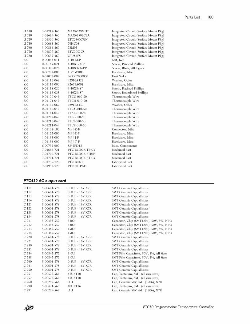
Parts List 180
PTC10 Programmable Temperature Controller
U 630 3-01717-360 MAX6629MUT Integrated Circuit (Surface Mount Pkg) U 710 3-01469-360 MAX6250BCSA Integrated Circuit (Surface Mount Pkg) U 720 3-01500-360 LTC2440CGN Integrated Circuit (Surface Mount Pkg) U 750 3-00663-360 74HC08 Integrated Circuit (Surface Mount Pkg) U 760 3-00814-360 78M05 Integrated Circuit (Surface Mount Pkg) U 770 3-01822-360 LTC2052CS Integrated Circuit (Surface Mount Pkg) U 780 3-00659-360 OP284FS Integrated Circuit (Surface Mount Pkg) Z 0 0-00043-011 4-40 KEP Nut, Kep Z 0 0-00187-021 4-40X1/4PP Screw, Panhead Phillips Z 0 0-00306-026 4-40X3/16PP Screw, Black, All Types Z 0 0-00772-000 1.5" WIRE Hardware, Misc. Z 0 0-01093-007 563002B00000 Heat Sinks Z 0 0-01116-062 92916A325 Washer, Other Z 0 0-01117-000 92671A005 Hardware, Misc. Z 0 0-01118-020 4-40X3/8" Screw, Flathead Phillips Z 0 0-01119-023 4-40X3/8" Screw, Roundhead Phillips Z 0 0-01120-049 TFCC-010-50 Thermocouple Wire Z 0 0-01121-049 TFCH-010-50 Thermocouple Wire Z 0 0-01159-062 92916A330 Washer, Other Z 0 0-01160-049 TFCY-010-50 Thermocouple Wire Z 0 0-01161-049 TFAL-010-50 Thermocouple Wire Z 0 0-01209-049 TFIR-010-50 Thermocouple Wire Z 0 0-01210-049 TFCI-010-50 Thermocouple Wire Z 0 0-01211-049 TFCP-010-50 Thermocouple Wire Z 0 1-01105-100 MPJ-K-F Connector, Misc. Z 0 1-01122-000 MPJ-E-F Hardware, Misc. Z 0 1-01193-000 MPJ-J-F Hardware, Misc. Z 0 1-01194-000 MPJ-T-F Hardware, Misc. Z 0 6-00735-600 S245PD12 Misc. Components Z 0 7-01699-721 PTC BLOCK TP CV Machined Part Z 0 7-01700-721 PTC BLOCK STRIP Machined Part Z 0 7-01701-721 PTC BLOCK BT CV Machined Part Z 0 7-01735-720 PTC BRKT Fabricated Part Z 0 7-01992-720 PTC SIL PAD Fabricated Part
PTC420 AC output card
C 111 5-00601-578 0.1UF - 16V X7R SMT Ceramic Cap, all sizes C 112 5-00601-578 0.1UF - 16V X7R SMT Ceramic Cap, all sizes C 113 5-00601-578 0.1UF - 16V X7R SMT Ceramic Cap, all sizes C 114 5-00601-578 0.1UF - 16V X7R SMT Ceramic Cap, all sizes C 121 5-00601-578 0.1UF - 16V X7R SMT Ceramic Cap, all sizes C 122 5-00601-578 0.1UF - 16V X7R SMT Ceramic Cap, all sizes C 123 5-00601-578 0.1UF - 16V X7R SMT Ceramic Cap, all sizes C 124 5-00601-578 0.1UF - 16V X7R SMT Ceramic Cap, all sizes C 211 5-00393-552 3300P Capacitor, Chip (SMT1206), 50V, 5%, NPO C 212 5-00393-552 3300P Capacitor, Chip (SMT1206), 50V, 5%, NPO C 213 5-00389-552 1500P Capacitor, Chip (SMT1206), 50V, 5%, NPO C 214 5-00389-552 1500P Capacitor, Chip (SMT1206), 50V, 5%, NPO C 220 5-00601-578 0.1UF - 16V X7R SMT Ceramic Cap, all sizes C 221 5-00601-578 0.1UF - 16V X7R SMT Ceramic Cap, all sizes C 230 5-00601-578 0.1UF - 16V X7R SMT Ceramic Cap, all sizes C 231 5-00601-578 0.1UF - 16V X7R SMT Ceramic Cap, all sizes C 234 5-00542-572 1.0U SMT Film Capacitors, 50V, 5%, All Sizes C 235 5-00542-572 1.0U SMT Film Capacitors, 50V, 5%, All Sizes C 240 5-00601-578 0.1UF - 16V X7R SMT Ceramic Cap, all sizes C 241 5-00601-578 0.1UF - 16V X7R SMT Ceramic Cap, all sizes C 250 5-00601-578 0.1UF - 16V X7R SMT Ceramic Cap, all sizes C 251 5-00522-569 47U/T10 Cap, Tantalum, SMT (all case sizes) C 252 5-00522-569 47U/T10 Cap, Tantalum, SMT (all case sizes) C 260 5-00299-568 .1U Cap, Ceramic 50V SMT (1206), X7R C 290 5-00471-569 10U/T16 Cap, Tantalum, SMT (all case sizes) C 291 5-00299-568 .1U Cap, Ceramic 50V SMT (1206), X7R

Parts List 181
PTC10 Programmable Temperature Controller
C 292 5-00471-569 10U/T16 Cap, Tantalum, SMT (all case sizes) C 293 5-00299-568 .1U Cap, Ceramic 50V SMT (1206), X7R C 294 5-00298-568 .01U Cap, Ceramic 50V SMT (1206), X7R D 111 3-00011-303 RED LED, T1 Package D 112 3-00011-303 RED LED, T1 Package D 211 3-00896-301 BAV99 Diode D 212 3-00896-301 BAV99 Diode D 213 3-00896-301 BAV99 Diode D 214 3-00896-301 BAV99 Diode D 231 3-01400-313 BAV199 Diode, SMT D 232 3-01400-313 BAV199 Diode, SMT D 262 3-00806-360 BAV170LT1 Integrated Circuit (Surface Mount Pkg) J 111 1-00251-130 10 PIN DIL Connector, Male J 201 1-01185-100 7690 Connector, Misc. J 202 1-01052-130 4 POS IN Connector, Male JD121 1-00234-109 96 PIN RT ANGLE DIN Connector, Male K 260 3-01056-335 24VDC DPDT Relay L 200 6-00757-604 390UH Inductor, Vertical Mount L 290 6-00236-631 FR47 Ferrite bead, SMT LS200 3-01739-335 AQ5A2ZP3/28VDC Relay PC1 7-01708-701 PTC, AC OUTPUT Printed Circuit Board Q 260 3-00601-360 MMBT3904LT1 Integrated Circuit (Surface Mount Pkg) R 112 4-01466-461 300 Thick Film, 5%, 200 ppm, Chip Resistor R 113 4-01466-461 300 Thick Film, 5%, 200 ppm, Chip Resistor R 200 4-01783-400 0.1 OHM - 5W Resistor, Misc. R 211 4-01544-461 510K Thick Film, 5%, 200 ppm, Chip Resistor R 212 4-01544-461 510K Thick Film, 5%, 200 ppm, Chip Resistor R 213 4-01551-461 1.0M Thick Film, 5%, 200 ppm, Chip Resistor R 214 4-01496-461 5.1K Thick Film, 5%, 200 ppm, Chip Resistor R 215 4-01551-461 1.0M Thick Film, 5%, 200 ppm, Chip Resistor R 216 4-01496-461 5.1K Thick Film, 5%, 200 ppm, Chip Resistor R 231 4-01538-461 300K Thick Film, 5%, 200 ppm, Chip Resistor R 232 4-01538-461 300K Thick Film, 5%, 200 ppm, Chip Resistor R 233 4-00434-408 4.990K Resistor, Metal Film, 1/8W, 0.1%, 25ppm R 234 4-00218-408 10.00K Resistor, Metal Film, 1/8W, 0.1%, 25ppm R 235 4-00434-408 4.990K Resistor, Metal Film, 1/8W, 0.1%, 25ppm R 236 4-00218-408 10.00K Resistor, Metal Film, 1/8W, 0.1%, 25ppm R 242 4-01242-462 20.0K Thin Film, 1%, 50 ppm, MELF Resistor R 243 4-01242-462 20.0K Thin Film, 1%, 50 ppm, MELF Resistor R 261 4-01495-461 4.7K Thick Film, 5%, 200 ppm, Chip Resistor R 262 4-01495-461 4.7K Thick Film, 5%, 200 ppm, Chip Resistor RN111 4-01707-463 47KX4D Resistor network, SMT, Leadless RN113 4-00911-463 4.7KX4D Resistor network, SMT, Leadless RN121 4-01707-463 47KX4D Resistor network, SMT, Leadless RN231 4-00911-463 4.7KX4D Resistor network, SMT, Leadless RN232 4-00912-463 10KX4D Resistor network, SMT, Leadless RN233 4-00912-463 10KX4D Resistor network, SMT, Leadless RN241 4-00912-463 10KX4D Resistor network, SMT, Leadless RN242 4-01707-463 47KX4D Resistor network, SMT, Leadless RV200 4-01784-435 V250LA10 Varistor, Zinc Oxide Nonlinear Resistor U 111 3-01740-360 ATMEGA16-16AC Integrated Circuit (Surface Mount Pkg) U 120 3-01498-360 74ABT16245CMTD Integrated Circuit (Surface Mount Pkg) U 220 3-01257-360 LMC6484AIM Integrated Circuit (Surface Mount Pkg) U 230 3-01257-360 LMC6484AIM Integrated Circuit (Surface Mount Pkg) U 240 3-01257-360 LMC6484AIM Integrated Circuit (Surface Mount Pkg) U 250 3-01741-360 MAX660M Integrated Circuit (Surface Mount Pkg) U 260 3-00741-360 74HC04 Integrated Circuit (Surface Mount Pkg) Z 0 0-00306-026 4-40X3/16PP Screw, Black, All Types Z 0 0-00428-000 SLEEVE Hardware, Misc. Z 0 0-00541-052 #22GRN/YEL Wire #22 UL1007 Z 0 0-00636-032 39-00-0047 FEM Termination Z 0 0-01174-007 AQ-HS-5A Heat Sinks Z 0 0-01175-002 49-2BK Power Entry Hardware Z 0 0-01244-052 8 1/2" BROWN Wire #22 UL1007

Parts List 182
PTC10 Programmable Temperature Controller
Z 0 0-01245-052 8 1/2" BLUE Wire #22 UL1007 Z 0 1-01054-179 4POS, VERT SING Connector Housing, Receptacle Z 0 1-01216-172 PTC AC OUTPUT Line Cord Z 0 7-01737-720 PTC BRKT Fabricated Part
PTC430 50W DC output card
C 111 5-00601-578 0.1UF - 16V X7R SMT Ceramic Cap, all sizes C 112 5-00601-578 0.1UF - 16V X7R SMT Ceramic Cap, all sizes C 113 5-00601-578 0.1UF - 16V X7R SMT Ceramic Cap, all sizes C 121 5-00601-578 0.1UF - 16V X7R SMT Ceramic Cap, all sizes C 122 5-00601-578 0.1UF - 16V X7R SMT Ceramic Cap, all sizes C 123 5-00601-578 0.1UF - 16V X7R SMT Ceramic Cap, all sizes C 124 5-00601-578 0.1UF - 16V X7R SMT Ceramic Cap, all sizes C 201 5-00389-552 1500P Capacitor, Chip (SMT1206), 50V, 5%, NPO C 202 5-00389-552 1500P Capacitor, Chip (SMT1206), 50V, 5%, NPO C 203 5-00606-578 1U / 100V SMT Ceramic Cap, all sizes C 204 5-00389-552 1500P Capacitor, Chip (SMT1206), 50V, 5%, NPO C 211 5-00607-553 10U / 50V SMT Capacitor, Electrolytic, 80V, +/-20% C 212 5-00607-553 10U / 50V SMT Capacitor, Electrolytic, 80V, +/-20% C 213 5-00607-553 10U / 50V SMT Capacitor, Electrolytic, 80V, +/-20% C 214 5-00608-553 100U /100V SMT Capacitor, Electrolytic, 80V, +/-20% C 215 5-00608-553 100U /100V SMT Capacitor, Electrolytic, 80V, +/-20% C 216 5-00605-578 .82UF / 25V SMT Ceramic Cap, all sizes C 230 5-00519-569 .33U/T35 Cap, Tantalum, SMT (all case sizes) C 231 5-00513-569 1U-16V A-CASE Cap, Tantalum, SMT (all case sizes) C 232 5-00629-568 1000P X 4 Cap, Ceramic 50V SMT (1206), X7R C 233 5-00299-568 .1U Cap, Ceramic 50V SMT (1206), X7R C 234 5-00299-568 .1U Cap, Ceramic 50V SMT (1206), X7R C 235 5-00299-568 .1U Cap, Ceramic 50V SMT (1206), X7R C 236 5-00299-568 .1U Cap, Ceramic 50V SMT (1206), X7R C 240 5-00299-568 .1U Cap, Ceramic 50V SMT (1206), X7R C 243 5-00299-568 .1U Cap, Ceramic 50V SMT (1206), X7R C 244 5-00299-568 .1U Cap, Ceramic 50V SMT (1206), X7R C 245 5-00627-578 0.1U X 4 SMT Ceramic Cap, all sizes C 250 5-00299-568 .1U Cap, Ceramic 50V SMT (1206), X7R C 251 5-00319-569 10U/T35 Cap, Tantalum, SMT (all case sizes) C 252 5-00299-568 .1U Cap, Ceramic 50V SMT (1206), X7R C 253 5-00319-569 10U/T35 Cap, Tantalum, SMT (all case sizes) C 254 5-00299-568 .1U Cap, Ceramic 50V SMT (1206), X7R C 255 5-00298-568 .01U Cap, Ceramic 50V SMT (1206), X7R C 261 5-00299-568 .1U Cap, Ceramic 50V SMT (1206), X7R C 270 5-00299-568 .1U Cap, Ceramic 50V SMT (1206), X7R C 271 5-00798-568 2.2U Cap, Ceramic 50V SMT (1206), X7R C 272 5-00525-578 1U SMT Ceramic Cap, all sizes C 273 5-00513-569 1U-16V A-CASE Cap, Tantalum, SMT (all case sizes) C 274 5-00654-500 .01UF X 4 Capacitor, Misc. C 275 5-00525-578 1U SMT Ceramic Cap, all sizes C 276 5-00525-578 1U SMT Ceramic Cap, all sizes C 277 5-00299-568 .1U Cap, Ceramic 50V SMT (1206), X7R C 281 5-00299-568 .1U Cap, Ceramic 50V SMT (1206), X7R C 290 5-00299-568 .1U Cap, Ceramic 50V SMT (1206), X7R C 300 5-00299-568 .1U Cap, Ceramic 50V SMT (1206), X7R C 310 5-00299-568 .1U Cap, Ceramic 50V SMT (1206), X7R C 311 5-00522-569 47U/T10 Cap, Tantalum, SMT (all case sizes) C 312 5-00522-569 47U/T10 Cap, Tantalum, SMT (all case sizes) D 111 3-00576-311 RED MINI LED, Subminiature D 211 3-00403-301 1N459A Diode D 212 3-01253-313 B270-13 Diode, SMT D 214 3-00626-301 MUR1100E Diode F 221 6-00644-611 1A 60V Fuse J 111 1-00251-130 10 PIN DIL Connector, Male J 201 0-01097-035 571-0100 Banana jack

Parts List 183
PTC10 Programmable Temperature Controller
J 202 0-01096-035 571-0500 Banana jack JD121 1-00234-109 96 PIN RT ANGLE DIN Connector, Male L 201 6-00512-631 2744045447 Ferrite bead, SMT L 202 6-00512-631 2744045447 Ferrite bead, SMT L 211 6-00645-609 330UH Inductor, Fixed, SMT L 251 6-00236-631 FR47 Ferrite bead, SMT PC1 7-01706-701 PTC, DC OUTPUT Printed Circuit Board Q 233 3-01254-360 BSS123LT1 Integrated Circuit (Surface Mount Pkg) Q 234 3-01254-360 BSS123LT1 Integrated Circuit (Surface Mount Pkg) Q 235 3-01254-360 BSS123LT1 Integrated Circuit (Surface Mount Pkg) Q 236 3-01254-360 BSS123LT1 Integrated Circuit (Surface Mount Pkg) Q 251 3-01819-360 IRF6218PBF Integrated Circuit (Surface Mount Pkg) Q 252 3-01819-360 IRF6218PBF Integrated Circuit (Surface Mount Pkg) Q 253 3-01819-360 IRF6218PBF Integrated Circuit (Surface Mount Pkg) Q 254 3-01820-360 IRF9520NPBF Integrated Circuit (Surface Mount Pkg) R 112 4-01466-461 300 Thick Film, 5%, 200 ppm, Chip Resistor R 201 4-01406-461 0 Thick Film, 5%, 200 ppm, Chip Resistor R 202 4-01406-461 0 Thick Film, 5%, 200 ppm, Chip Resistor R 203 4-01406-461 0 Thick Film, 5%, 200 ppm, Chip Resistor R 204 4-01406-461 0 Thick Film, 5%, 200 ppm, Chip Resistor R 205 4-01406-461 0 Thick Film, 5%, 200 ppm, Chip Resistor R 206 4-01186-462 5.23K Thin Film, 1%, 50 ppm, MELF Resistor R 207 4-01309-462 100K Thin Film, 1%, 50 ppm, MELF Resistor R 208 4-00436-409 .1 Resistor, Wire Wound R 211 4-01147-462 2.05K Thin Film, 1%, 50 ppm, MELF Resistor R 212 4-01292-462 66.5K Thin Film, 1%, 50 ppm, MELF Resistor R 213 4-01134-462 1.50K Thin Film, 1%, 50 ppm, MELF Resistor R 231 4-01173-462 3.83K Thin Film, 1%, 50 ppm, MELF Resistor R 232 4-01155-462 2.49K Thin Film, 1%, 50 ppm, MELF Resistor R 233 4-01117-462 1.00K Thin Film, 1%, 50 ppm, MELF Resistor R 234 4-01146-462 2.00K Thin Film, 1%, 50 ppm, MELF Resistor R 235 4-01173-462 3.83K Thin Film, 1%, 50 ppm, MELF Resistor R 236 4-01155-462 2.49K Thin Film, 1%, 50 ppm, MELF Resistor R 237 4-01117-462 1.00K Thin Film, 1%, 50 ppm, MELF Resistor R 238 4-01146-462 2.00K Thin Film, 1%, 50 ppm, MELF Resistor R 239 4-01173-462 3.83K Thin Film, 1%, 50 ppm, MELF Resistor R 240 4-01155-462 2.49K Thin Film, 1%, 50 ppm, MELF Resistor R 241 4-01117-462 1.00K Thin Film, 1%, 50 ppm, MELF Resistor R 242 4-01146-462 2.00K Thin Film, 1%, 50 ppm, MELF Resistor R 243 4-01173-462 3.83K Thin Film, 1%, 50 ppm, MELF Resistor R 244 4-01201-462 7.50K Thin Film, 1%, 50 ppm, MELF Resistor R 245 4-01146-462 2.00K Thin Film, 1%, 50 ppm, MELF Resistor R 246 4-01088-462 499 Thin Film, 1%, 50 ppm, MELF Resistor R 247 4-01155-462 2.49K Thin Film, 1%, 50 ppm, MELF Resistor R 248 4-01117-462 1.00K Thin Film, 1%, 50 ppm, MELF Resistor R 249 4-01146-462 2.00K Thin Film, 1%, 50 ppm, MELF Resistor R 251 4-02456-400 1 OHM - 1% Resistor, Misc. R 252 4-01712-409 4.0 5W Resistor, Wire Wound R 253 4-01729-449 20.0 / 100PPM Resistor, Metal Film 1/2W, 1%, 50ppm R 254 4-01320-462 130K Thin Film, 1%, 50 ppm, MELF Resistor R 255 4-01146-462 2.00K Thin Film, 1%, 50 ppm, MELF Resistor R 256 4-01146-462 2.00K Thin Film, 1%, 50 ppm, MELF Resistor R 257 4-01146-462 2.00K Thin Film, 1%, 50 ppm, MELF Resistor R 263 4-01404-462 976K Thin Film, 1%, 50 ppm, MELF Resistor R 264 4-01296-462 73.2K Thin Film, 1%, 50 ppm, MELF Resistor R 273 4-01242-462 20.0K Thin Film, 1%, 50 ppm, MELF Resistor R 274 4-01117-462 1.00K Thin Film, 1%, 50 ppm, MELF Resistor RN111 4-01707-463 47KX4D Resistor network, SMT, Leadless RN112 4-01707-463 47KX4D Resistor network, SMT, Leadless RN113 4-00910-463 1.0KX4D Resistor network, SMT, Leadless RN121 4-01707-463 47KX4D Resistor network, SMT, Leadless RN271 4-00910-463 1.0KX4D Resistor network, SMT, Leadless RN272 4-01764-463 10X4D Resistor network, SMT, Leadless RN273 4-00911-463 4.7KX4D Resistor network, SMT, Leadless

Parts List 184
PTC10 Programmable Temperature Controller
RN291 4-00910-463 1.0KX4D Resistor network, SMT, Leadless RN292 4-00911-463 4.7KX4D Resistor network, SMT, Leadless U 110 3-01696-360 ATMEGA64-16AC Integrated Circuit (Surface Mount Pkg) U 120 3-01498-360 74ABT16245CMTD Integrated Circuit (Surface Mount Pkg) U 140 3-00413-340 LM34DZ Integrated Circuit (Thru-hole Pkg) U 210 3-01255-360 LM2586T-ADJ Integrated Circuit (Surface Mount Pkg) U 230 3-00814-360 78M05 Integrated Circuit (Surface Mount Pkg) U 233 3-01821-360 LTC6102HMS Integrated Circuit (Surface Mount Pkg) U 234 3-01821-360 LTC6102HMS Integrated Circuit (Surface Mount Pkg) U 235 3-01821-360 LTC6102HMS Integrated Circuit (Surface Mount Pkg) U 236 3-01821-360 LTC6102HMS Integrated Circuit (Surface Mount Pkg) U 240 3-00675-360 LTC1655 Integrated Circuit (Surface Mount Pkg) U 243 3-00795-360 74AC138 Integrated Circuit (Surface Mount Pkg) U 244 3-01256-360 MAX4634EUB Integrated Circuit (Surface Mount Pkg) U 250 3-01822-360 LTC2052CS Integrated Circuit (Surface Mount Pkg) U 260 3-01386-360 DG408DY Integrated Circuit (Surface Mount Pkg) U 270 3-01257-360 LMC6484AIM Integrated Circuit (Surface Mount Pkg) U 271 3-01186-360 MAX6241BCSA Integrated Circuit (Surface Mount Pkg) U 280 3-01258-360 LTC2433-1CMS Integrated Circuit (Surface Mount Pkg) U 290 3-01366-360 DG333ADW Integrated Circuit (Surface Mount Pkg) U 300 3-01717-360 MAX6629MUT Integrated Circuit (Surface Mount Pkg) U 310 3-01741-360 MAX660M Integrated Circuit (Surface Mount Pkg) Z 0 0-00187-021 4-40X1/4PP Screw, Panhead Phillips Z 0 0-00246-043 #8 X 1/16 Washer, nylon Z 0 0-00306-026 4-40X3/16PP Screw, Black, All Types Z 0 0-01092-007 78060 Heat Sinks Z 0 0-01093-007 563002B00000 Heat Sinks Z 0 0-01094-067 MAX02 Pins & Clips Z 0 0-01095-003 HF300P-.001-AC Insulators Z 0 7-01733-720 PTC BRACKET Fabricated Part
PTC440 TEC driver
C110 5-00513 1U-16V A-CASE SMT Tantalum, 16V, A-case (1206, but NEEDS POLARITY mark) C111 5-00601 0.1UF - 16V X7R C112 5-00601 0.1UF - 16V X7R C113 5-00601 0.1UF - 16V X7R C121 5-00601 0.1UF - 16V X7R C122 5-00601 0.1UF - 16V X7R C123 5-00601 0.1UF - 16V X7R C124 5-00601 0.1UF - 16V X7R C200 5-00299 .1U Capacitor, Mono, 50V, 10%, X7R, 1206 C202 5-00516 330U Capacitor, Electrolytic, High Ripple, High Temp (-55/+105 DEG C) C203 5-00520 4.7U/T35 SMD Tantalum, C-Case C210 5-00299 .1U Capacitor, Mono, 50V, 10%, X7R, 1206 C211 5-00299 .1U Capacitor, Mono, 50V, 10%, X7R, 1206 C212 5-00399 .01U - 5% Capacitor, Mono, 50V, 5%, X7R, 1206 C213 5-00388 1200P Capacitor, Mono, 50V, 5%, NPO, 1206 C216 5-00526 22U-T16 SMD Tantalum, C-Case C223 5-00388 1200P Capacitor, Mono, 50V, 5%, NPO, 1206 C226 5-00299 .1U Capacitor, Mono, 50V, 10%, X7R, 1206 C231 5-00299 .1U Capacitor, Mono, 50V, 10%, X7R, 1206 C232 5-00299 .1U Capacitor, Mono, 50V, 10%, X7R, 1206 C233 5-00299 .1U Capacitor, Mono, 50V, 10%, X7R, 1206 C240 5-00299 .1U Capacitor, Mono, 50V, 10%, X7R, 1206 C241 5-00299 .1U Capacitor, Mono, 50V, 10%, X7R, 1206 C242 5-00299 .1U Capacitor, Mono, 50V, 10%, X7R, 1206 C250 5-00299 .1U Capacitor, Mono, 50V, 10%, X7R, 1206 C251 5-00299 .1U Capacitor, Mono, 50V, 10%, X7R, 1206 C252 5-00299 .1U Capacitor, Mono, 50V, 10%, X7R, 1206 C260 5-00526 22U-T16 SMD Tantalum, C-Case C261 5-00299 .1U Capacitor, Mono, 50V, 10%, X7R, 1206

Parts List 185
PTC10 Programmable Temperature Controller
C262 5-00299 .1U Capacitor, Mono, 50V, 10%, X7R, 1206 C263 5-00526 22U-T16 SMD Tantalum, C-Case C280 5-00299 .1U Capacitor, Mono, 50V, 10%, X7R, 1206 C282 5-00299 .1U Capacitor, Mono, 50V, 10%, X7R, 1206 C283 5-00299 .1U Capacitor, Mono, 50V, 10%, X7R, 1206 C284 5-00299 .1U Capacitor, Mono, 50V, 10%, X7R, 1206 C290 5-00299 .1U Capacitor, Mono, 50V, 10%, X7R, 1206 C291 5-00470 2.2U/T16 SMD Tantalum, Y-Case C292 5-00470 2.2U/T16 SMD Tantalum, Y-Case C293 5-00525 1U CAP 1UF 25V CERAMIC Y5V 1206 +80/ -20% C300 5-00299 .1U Capacitor, Mono, 50V, 10%, X7R, 1206 C302 5-00299 .1U Capacitor, Mono, 50V, 10%, X7R, 1206 C310 5-00164 4.7UF - 1812 Capacitor, Ceramic, 50V, 10%, SL, Rad C311 5-00399 .01U - 5% Capacitor, Mono, 50V, 5%, X7R, 1206 C312 5-00119 22UF Capacitor, Silver Mica, 500V, 5%, DM15 C320 5-00299 .1U Capacitor, Mono, 50V, 10%, X7R, 1206 C321 5-00299 .1U Capacitor, Mono, 50V, 10%, X7R, 1206 C330 5-00519 .33U/T35 SMD Tantalum, Y-Case C331 5-00513 1U-16V A-CASE SMT Tantalum, 16V, A-case (1206, but NEEDS POLARITY mark) C340 5-00519 .33U/T35 SMD Tantalum, Y-Case C341 5-00319 10U/T35 SMD Tantalum, D-Case C342 5-00319 10U/T35 SMD Tantalum, D-Case C360 5-00299 .1U Capacitor, Mono, 50V, 10%, X7R, 1206 C400 5-00520 4.7U/T35 SMD Tantalum, C-Case C401 5-00520 4.7U/T35 SMD Tantalum, C-Case C402 5-00525 1U CAP 1UF 25V CERAMIC Y5V 1206 +80/ -20% C410 5-00299 .1U Capacitor, Mono, 50V, 10%, X7R, 1206 C411 5-00525 1U CAP 1UF 25V CERAMIC Y5V 1206 +80/ -20% C420 5-00299 .1U Capacitor, Mono, 50V, 10%, X7R, 1206 C421 5-00299 .1U Capacitor, Mono, 50V, 10%, X7R, 1206 C430 5-00299 .1U Capacitor, Mono, 50V, 10%, X7R, 1206 C431 5-00525 1U CAP 1UF 25V CERAMIC Y5V 1206 +80/ -20% C440 5-00299 .1U Capacitor, Mono, 50V, 10%, X7R, 1206 C451 5-00525 1U CAP 1UF 25V CERAMIC Y5V 1206 +80/ -20% C452 5-00525 1U CAP 1UF 25V CERAMIC Y5V 1206 +80/ -20% C500 5-00299 .1U Capacitor, Mono, 50V, 10%, X7R, 1206 C510 5-00299 .1U Capacitor, Mono, 50V, 10%, X7R, 1206 C511 5-00299 .1U Capacitor, Mono, 50V, 10%, X7R, 1206 C530 5-00299 .1U Capacitor, Mono, 50V, 10%, X7R, 1206 C540 5-00299 .1U Capacitor, Mono, 50V, 10%, X7R, 1206 C572 5-00519 .33U/T35 SMD Tantalum, Y-Case C573 5-00513 1U-16V A-CASE SMT Tantalum, 16V, A-case (1206, but NEEDS POLARITY mark) D111 3-00576 RED MINI LED, Subminiature, 1.8mm (T 3/4) D234 3-00945 BAT54S Dual schottky diode, series connection D300 3-01400 BAV199 dual series switching diode, low leakage D312 3-01936 PDS560-13 D341 3-01400 BAV199 dual series switching diode, low leakage D400 3-00198 1N5231B 1N5231B, 5.1V, 500mW, DO-35 ZENER DIODE D402 3-01430 BAS40-05 Dual Schottky, Common Cathode D451 3-00945 BAT54S Dual schottky diode, series connection ISO510 3-01320 HCPL-2630 ISO511 3-01320 HCPL-2630 ISO530 3-01320 HCPL-2630 J230 1-00370 15 PIN D DB Female, Right Angle, .318 JDR121 1-00234 96 PIN RT ANGLE 3 Row, Right Angle Mount L231 6-00512 2744045447 Ferrite Bead, Common Mode, SMD, Type 44, 3312 L232 6-00512 2744045447 Ferrite Bead, Common Mode, SMD, Type 44, 3312 L312 6-00815 10UH PCB 7-02093 PTC440 PELTIER Q202 3-00944 IRF4905 P-channel Power MOSFET, ultra-low Ron Q211 3-01678 IRF1010EZ Q212 3-00944 IRF4905 P-channel Power MOSFET, ultra-low Ron Q221 3-01678 IRF1010EZ

Parts List 186
PTC10 Programmable Temperature Controller
Q222 3-00944 IRF4905 P-channel Power MOSFET, ultra-low Ron R112 4-01466 300 Resistor, Thick Film, 5%, 200 ppm, SMT R204 4-01178 4.32K Resistor, Thin Film, 1%, 50 ppm, MELF R205 4-01406 0 Resistor, Thick Film, 5%, 300 ppm, SMT R206 4-01213 10.0K Resistor, Thin Film, 1%, 50 ppm, MELF R207 4-01213 10.0K Resistor, Thin Film, 1%, 50 ppm, MELF R211 4-01213 10.0K Resistor, Thin Film, 1%, 50 ppm, MELF R212 4-01146 2.00K Resistor, Thin Film, 1%, 50 ppm, MELF R213 4-01146 2.00K Resistor, Thin Film, 1%, 50 ppm, MELF R216 4-01178 4.32K Resistor, Thin Film, 1%, 50 ppm, MELF R217 4-01146 2.00K Resistor, Thin Film, 1%, 50 ppm, MELF R218 4-01213 10.0K Resistor, Thin Film, 1%, 50 ppm, MELF R221 4-01213 10.0K Resistor, Thin Film, 1%, 50 ppm, MELF R222 4-01213 10.0K Resistor, Thin Film, 1%, 50 ppm, MELF R223 4-01213 10.0K Resistor, Thin Film, 1%, 50 ppm, MELF R224 4-01146 2.00K Resistor, Thin Film, 1%, 50 ppm, MELF R225 4-01213 10.0K Resistor, Thin Film, 1%, 50 ppm, MELF R226 4-01213 10.0K Resistor, Thin Film, 1%, 50 ppm, MELF R227 4-01146 2.00K Resistor, Thin Film, 1%, 50 ppm, MELF R228 4-01213 10.0K Resistor, Thin Film, 1%, 50 ppm, MELF R231 4-01021 100 Resistor, Thin Film, 1%, 50 ppm, MELF R232 4-01050 200 Resistor, Thin Film, 1%, 50 ppm, MELF R233 4-01050 200 Resistor, Thin Film, 1%, 50 ppm, MELF R234 4-01117 1.00K Resistor, Thin Film, 1%, 50 ppm, MELF R240 4-01762 0.05 R242 4-01213 10.0K Resistor, Thin Film, 1%, 50 ppm, MELF R252 4-01213 10.0K Resistor, Thin Film, 1%, 50 ppm, MELF R281 4-01213 10.0K Resistor, Thin Film, 1%, 50 ppm, MELF R282 4-01213 10.0K Resistor, Thin Film, 1%, 50 ppm, MELF R321 4-01205 8.25K Resistor, Thin Film, 1%, 50 ppm, MELF R322 4-01192 6.04K Resistor, Thin Film, 1%, 50 ppm, MELF R323 4-01171 3.65K Resistor, Thin Film, 1%, 50 ppm, MELF R324 4-01129 1.33K Resistor, Thin Film, 1%, 50 ppm, MELF R325 4-01117 1.00K Resistor, Thin Film, 1%, 50 ppm, MELF R340 4-01058 243 Resistor, Thin Film, 1%, 50 ppm, MELF R341 4-01163 3.01K Resistor, Thin Film, 1%, 50 ppm, MELF R410 4-01213 10.0K Resistor, Thin Film, 1%, 50 ppm, MELF R411 4-01213 10.0K Resistor, Thin Film, 1%, 50 ppm, MELF R412 4-01117 1.00K Resistor, Thin Film, 1%, 50 ppm, MELF R413 4-01021 100 Resistor, Thin Film, 1%, 50 ppm, MELF R414 4-00930 11.3 Resistor, Thin Film, 1%, 50 ppm, MELF R415 4-01703 2.490K R421 4-01146 2.00K Resistor, Thin Film, 1%, 50 ppm, MELF R431 4-01213 10.0K Resistor, Thin Film, 1%, 50 ppm, MELF R432 4-01670 20K 1% MPM Series Resistive Divider, Thin Film, 10.0K x 2, 0.1W, 1% R441 4-01703 2.490K R442 4-01213 10.0K Resistor, Thin Film, 1%, 50 ppm, MELF R443 4-01146 2.00K Resistor, Thin Film, 1%, 50 ppm, MELF R444 4-01050 200 Resistor, Thin Film, 1%, 50 ppm, MELF R451 4-01213 10.0K Resistor, Thin Film, 1%, 50 ppm, MELF R452 4-01213 10.0K Resistor, Thin Film, 1%, 50 ppm, MELF RN111 4-01707 47KX4D RN112 4-01707 47KX4D RN113 4-00910 1.0KX4D Network, DIP, Isolated, 1/16W, 5%, Tiny RN121 4-01707 47KX4D RN510 4-00909 470X4D Network, DIP, Isolated, 1/16W, 5%, Tiny RN512 4-00909 470X4D Network, DIP, Isolated, 1/16W, 5%, Tiny RN530 4-00909 470X4D Network, DIP, Isolated, 1/16W, 5%, Tiny RN532 4-00909 470X4D Network, DIP, Isolated, 1/16W, 5%, Tiny U110 3-01696 ATMEGA64-16AC U120 3-01498 74ABT16245CMTD U140 3-00413 LM34DZ LM34 Precision Temperature Sensor, Fahrenheit U200 3-00675 LTC1655 16 bit Rail-Rail DAC

Parts List 187
PTC10 Programmable Temperature Controller
U210 3-00581 AD822 AD822JR Dual JFET Single supply rail to rail op amp U230 3-01443 AQW225NA AQW225N, Dual PhotoMOS U240 3-01685 LT1991IMS U250 3-01685 LT1991IMS U260 3-01451 ADR421AR Low Noise, 2.048, 2.500 V reference U280 3-01978 LT1368CS8/#PBF U290 3-01938 LTC2445CUHF U291 3-01469 MAX6250BCSA +5V Reference U300 3-00741 74HC04 74HC04, Hex Inverter U310 3-01939 LM22678TJ-ADJ U320 3-00956 MAX4602CWE 2.5 OHM CMOS, QUAD SWT., 16 WIDE SO U330 3-00814 78M05 78M05, U340 3-01977 LM317MABDTG U360 3-01717 MAX6629MUT U400 3-01451 ADR421AR Low Noise, 2.048, 2.500 V reference U410 3-00643 DG211BDY-ROHS DG211BDY, Quad Analog Switch U420 3-01370 OPA277UA OPA277A, Precision Op-Amp, 20 ªV typ., 1 MHz typ., SO-8 U430 3-01683 OPA333AIDBVT U440 3-01683 OPA333AIDBVT U500 3-00663 74HC08 74HC08, Quad 2-Input AND Gate U540 3-00787 74HC595 74HC595, 8 Bit Serial Input, Parallel Output Shift Register U570 3-01979 79M05CDT/RK Z1 0-00150 4-40X1/4PF Z10 0-01094 MAX02 Z11 0-01094 MAX02 Z12 0-01094 MAX02 Z13 0-01095 HF300P-.001-AC Z14 7-02095 PTC440 FLANGE Z2 0-00150 4-40X1/4PF Z3 0-00246 #8 X 1/16 Z4 0-00246 #8 X 1/16 Z5 0-00306 4-40X3/16PP Z6 0-00306 4-40X3/16PP Z7 0-01092 78060 Z8 0-01094 MAX02 Z9 0-01094 MAX02
PTC510 analog I/O card
C 101 5-00601-578 0.1UF - 16V X7R SMT Ceramic Cap, all sizes C 102 5-00601-578 0.1UF - 16V X7R SMT Ceramic Cap, all sizes C 103 5-00601-578 0.1UF - 16V X7R SMT Ceramic Cap, all sizes C 105 5-00601-578 0.1UF - 16V X7R SMT Ceramic Cap, all sizes C 106 5-00601-578 0.1UF - 16V X7R SMT Ceramic Cap, all sizes C 107 5-00601-578 0.1UF - 16V X7R SMT Ceramic Cap, all sizes C 108 5-00601-578 0.1UF - 16V X7R SMT Ceramic Cap, all sizes C 201 5-00470-569 2.2U/T16 Cap, Tantalum, SMT (all case sizes) C 202 5-00525-578 1U SMT Ceramic Cap, all sizes C 203 5-00470-569 2.2U/T16 Cap, Tantalum, SMT (all case sizes) C 204 5-00299-568 .1U Cap, Ceramic 50V SMT (1206), X7R C 205 5-00471-569 10U/T16 Cap, Tantalum, SMT (all case sizes) C 206 5-00527-568 .47U Cap, Ceramic 50V SMT (1206), X7R C 207 5-00601-578 0.1UF - 16V X7R SMT Ceramic Cap, all sizes C 208 5-00601-578 0.1UF - 16V X7R SMT Ceramic Cap, all sizes C 209 5-00527-568 .47U Cap, Ceramic 50V SMT (1206), X7R C 210 5-00527-568 .47U Cap, Ceramic 50V SMT (1206), X7R C 211 5-00527-568 .47U Cap, Ceramic 50V SMT (1206), X7R C 212 5-00601-578 0.1UF - 16V X7R SMT Ceramic Cap, all sizes C 213 5-00601-578 0.1UF - 16V X7R SMT Ceramic Cap, all sizes C 214 5-00601-578 0.1UF - 16V X7R SMT Ceramic Cap, all sizes C 215 5-00601-578 0.1UF - 16V X7R SMT Ceramic Cap, all sizes C 216 5-00627-578 0.1U X 4 SMT Ceramic Cap, all sizes C 217 5-00601-578 0.1UF - 16V X7R SMT Ceramic Cap, all sizes

Parts List 188
PTC10 Programmable Temperature Controller
C 225 5-00601-578 0.1UF - 16V X7R SMT Ceramic Cap, all sizes C 226 5-00601-578 0.1UF - 16V X7R SMT Ceramic Cap, all sizes C 227 5-00381-552 330P Capacitor, Chip (SMT1206), 50V, 5%, NPO C 232 5-00299-568 .1U Cap, Ceramic 50V SMT (1206), X7R C 233 5-00471-569 10U/T16 Cap, Tantalum, SMT (all case sizes) C 302 5-00601-578 0.1UF - 16V X7R SMT Ceramic Cap, all sizes C 310 5-00299-568 .1U Cap, Ceramic 50V SMT (1206), X7R C 311 5-00299-568 .1U Cap, Ceramic 50V SMT (1206), X7R C 330 5-00299-568 .1U Cap, Ceramic 50V SMT (1206), X7R C 331 5-00299-568 .1U Cap, Ceramic 50V SMT (1206), X7R C 340 5-00601-578 0.1UF - 16V X7R SMT Ceramic Cap, all sizes C 351 5-00035-521 47U Capacitor, Electrolytic, 25V, 20%, Rad C 352 5-00519-569 .33U/T35 Cap, Tantalum, SMT (all case sizes) C 353 5-00513-569 1U-16V A-CASE Cap, Tantalum, SMT (all case sizes) C 361 5-00035-521 47U Capacitor, Electrolytic, 25V, 20%, Rad C 362 5-00519-569 .33U/T35 Cap, Tantalum, SMT (all case sizes) C 363 5-00513-569 1U-16V A-CASE Cap, Tantalum, SMT (all case sizes) C 371 5-00035-521 47U Capacitor, Electrolytic, 25V, 20%, Rad C 372 5-00519-569 .33U/T35 Cap, Tantalum, SMT (all case sizes) C 373 5-00513-569 1U-16V A-CASE Cap, Tantalum, SMT (all case sizes) D 101 3-00011-303 RED LED, T1 Package D 201 3-00544-360 BAV70LT1-ROHS Integrated Circuit (Surface Mount Pkg) D 202 3-00544-360 BAV70LT1-ROHS Integrated Circuit (Surface Mount Pkg) D 203 3-00544-360 BAV70LT1-ROHS Integrated Circuit (Surface Mount Pkg) D 204 3-00544-360 BAV70LT1-ROHS Integrated Circuit (Surface Mount Pkg) D 246 3-01384-301 MMBZ5232BLT1 Diode D 301 3-01880-313 SMBJ12CA Diode, SMT D 302 3-01880-313 SMBJ12CA Diode, SMT D 303 3-01880-313 SMBJ12CA Diode, SMT D 304 3-01880-313 SMBJ12CA Diode, SMT D 341 3-00011-303 RED LED, T1 Package D 342 3-00011-303 RED LED, T1 Package D 343 3-00011-303 RED LED, T1 Package D 344 3-00011-303 RED LED, T1 Package F 301 6-00773-611 1206L020 Fuse F 302 6-00773-611 1206L020 Fuse F 303 6-00773-611 1206L020 Fuse F 304 6-00773-611 1206L020 Fuse IS310 3-01320-340 HCPL-2630 Integrated Circuit (Thru-hole Pkg) IS311 3-01320-340 HCPL-2630 Integrated Circuit (Thru-hole Pkg) IS330 3-01320-340 HCPL-2630 Integrated Circuit (Thru-hole Pkg) J 101 1-00251-130 10 PIN DIL Connector, Male J 301 1-00233-120 RT ANGLE Connector, BNC J 302 1-00233-120 RT ANGLE Connector, BNC J 303 1-00233-120 RT ANGLE Connector, BNC J 304 1-00233-120 RT ANGLE Connector, BNC JD101 1-00234-109 96 PIN RT ANGLE DIN Connector, Male L 351 6-00174-630 6611 TYPE 43 Ferrite Beads L 352 6-00684-609 10UH Inductor, Fixed, SMT L 361 6-00174-630 6611 TYPE 43 Ferrite Beads L 362 6-00684-609 10UH Inductor, Fixed, SMT L 371 6-00174-630 6611 TYPE 43 Ferrite Beads L 372 6-00684-609 10UH Inductor, Fixed, SMT PC1 7-01709-701 PTC Printed Circuit Board R 101 4-01466-461 300 Thick Film, 5%, 200 ppm, Chip Resistor R 201 4-01230-462 15.0K Thin Film, 1%, 50 ppm, MELF Resistor R 202 4-01213-462 10.0K Thin Film, 1%, 50 ppm, MELF Resistor R 203 4-01213-462 10.0K Thin Film, 1%, 50 ppm, MELF Resistor R 204 4-01155-462 2.49K Thin Film, 1%, 50 ppm, MELF Resistor R 205 4-01213-462 10.0K Thin Film, 1%, 50 ppm, MELF Resistor R 206 4-01155-462 2.49K Thin Film, 1%, 50 ppm, MELF Resistor R 207 4-01213-462 10.0K Thin Film, 1%, 50 ppm, MELF Resistor R 208 4-01155-462 2.49K Thin Film, 1%, 50 ppm, MELF Resistor R 209 4-01213-462 10.0K Thin Film, 1%, 50 ppm, MELF Resistor
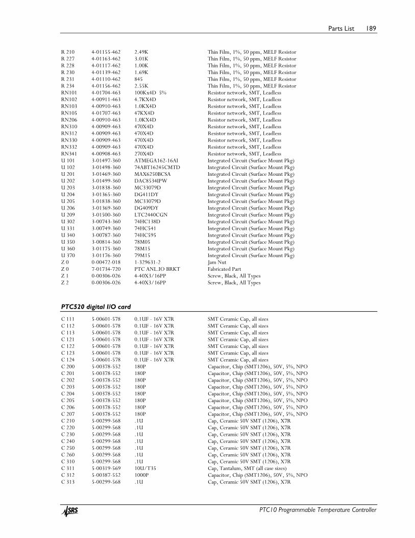
Parts List 189
PTC10 Programmable Temperature Controller
R 210 4-01155-462 2.49K Thin Film, 1%, 50 ppm, MELF Resistor R 227 4-01163-462 3.01K Thin Film, 1%, 50 ppm, MELF Resistor R 228 4-01117-462 1.00K Thin Film, 1%, 50 ppm, MELF Resistor R 230 4-01139-462 1.69K Thin Film, 1%, 50 ppm, MELF Resistor R 231 4-01110-462 845 Thin Film, 1%, 50 ppm, MELF Resistor R 234 4-01156-462 2.55K Thin Film, 1%, 50 ppm, MELF Resistor RN101 4-01704-463 100Kx4D 5% Resistor network, SMT, Leadless RN102 4-00911-463 4.7KX4D Resistor network, SMT, Leadless RN103 4-00910-463 1.0KX4D Resistor network, SMT, Leadless RN105 4-01707-463 47KX4D Resistor network, SMT, Leadless RN206 4-00910-463 1.0KX4D Resistor network, SMT, Leadless RN310 4-00909-463 470X4D Resistor network, SMT, Leadless RN312 4-00909-463 470X4D Resistor network, SMT, Leadless RN330 4-00909-463 470X4D Resistor network, SMT, Leadless RN332 4-00909-463 470X4D Resistor network, SMT, Leadless RN341 4-00908-463 270X4D Resistor network, SMT, Leadless U 101 3-01497-360 ATMEGA162-16AI Integrated Circuit (Surface Mount Pkg) U 102 3-01498-360 74ABT16245CMTD Integrated Circuit (Surface Mount Pkg) U 201 3-01469-360 MAX6250BCSA Integrated Circuit (Surface Mount Pkg) U 202 3-01499-360 DAC8534IPW Integrated Circuit (Surface Mount Pkg) U 203 3-01838-360 MC33079D Integrated Circuit (Surface Mount Pkg) U 204 3-01365-360 DG411DY Integrated Circuit (Surface Mount Pkg) U 205 3-01838-360 MC33079D Integrated Circuit (Surface Mount Pkg) U 206 3-01369-360 DG409DY Integrated Circuit (Surface Mount Pkg) U 209 3-01500-360 LTC2440CGN Integrated Circuit (Surface Mount Pkg) U 302 3-00743-360 74HC138D Integrated Circuit (Surface Mount Pkg) U 331 3-00749-360 74HC541 Integrated Circuit (Surface Mount Pkg) U 340 3-00787-360 74HC595 Integrated Circuit (Surface Mount Pkg) U 350 3-00814-360 78M05 Integrated Circuit (Surface Mount Pkg) U 360 3-01175-360 78M15 Integrated Circuit (Surface Mount Pkg) U 370 3-01176-360 79M15 Integrated Circuit (Surface Mount Pkg) Z 0 0-00472-018 1-329631-2 Jam Nut Z 0 7-01734-720 PTC ANL.IO BRKT Fabricated Part Z 1 0-00306-026 4-40X3/16PP Screw, Black, All Types Z 2 0-00306-026 4-40X3/16PP Screw, Black, All Types
PTC520 digital I/O card
C 111 5-00601-578 0.1UF - 16V X7R SMT Ceramic Cap, all sizes C 112 5-00601-578 0.1UF - 16V X7R SMT Ceramic Cap, all sizes C 113 5-00601-578 0.1UF - 16V X7R SMT Ceramic Cap, all sizes C 121 5-00601-578 0.1UF - 16V X7R SMT Ceramic Cap, all sizes C 122 5-00601-578 0.1UF - 16V X7R SMT Ceramic Cap, all sizes C 123 5-00601-578 0.1UF - 16V X7R SMT Ceramic Cap, all sizes C 124 5-00601-578 0.1UF - 16V X7R SMT Ceramic Cap, all sizes C 200 5-00378-552 180P Capacitor, Chip (SMT1206), 50V, 5%, NPO C 201 5-00378-552 180P Capacitor, Chip (SMT1206), 50V, 5%, NPO C 202 5-00378-552 180P Capacitor, Chip (SMT1206), 50V, 5%, NPO C 203 5-00378-552 180P Capacitor, Chip (SMT1206), 50V, 5%, NPO C 204 5-00378-552 180P Capacitor, Chip (SMT1206), 50V, 5%, NPO C 205 5-00378-552 180P Capacitor, Chip (SMT1206), 50V, 5%, NPO C 206 5-00378-552 180P Capacitor, Chip (SMT1206), 50V, 5%, NPO C 207 5-00378-552 180P Capacitor, Chip (SMT1206), 50V, 5%, NPO C 210 5-00299-568 .1U Cap, Ceramic 50V SMT (1206), X7R C 220 5-00299-568 .1U Cap, Ceramic 50V SMT (1206), X7R C 230 5-00299-568 .1U Cap, Ceramic 50V SMT (1206), X7R C 240 5-00299-568 .1U Cap, Ceramic 50V SMT (1206), X7R C 250 5-00299-568 .1U Cap, Ceramic 50V SMT (1206), X7R C 260 5-00299-568 .1U Cap, Ceramic 50V SMT (1206), X7R C 310 5-00299-568 .1U Cap, Ceramic 50V SMT (1206), X7R C 311 5-00319-569 10U/T35 Cap, Tantalum, SMT (all case sizes) C 312 5-00387-552 1000P Capacitor, Chip (SMT1206), 50V, 5%, NPO C 313 5-00299-568 .1U Cap, Ceramic 50V SMT (1206), X7R

Parts List 190
PTC10 Programmable Temperature Controller
C 314 5-00381-552 330P Capacitor, Chip (SMT1206), 50V, 5%, NPO C 316 5-00519-569 .33U/T35 Cap, Tantalum, SMT (all case sizes) C 360 5-00513-569 1U-16V A-CASE Cap, Tantalum, SMT (all case sizes) C 361 5-00519-569 .33U/T35 Cap, Tantalum, SMT (all case sizes) C 362 5-00628-569 22U - 35V Cap, Tantalum, SMT (all case sizes) C 364 5-00381-552 330P Capacitor, Chip (SMT1206), 50V, 5%, NPO C 410 5-00299-568 .1U Cap, Ceramic 50V SMT (1206), X7R C 420 5-00299-568 .1U Cap, Ceramic 50V SMT (1206), X7R D 111 3-00576-311 RED MINI LED, Subminiature D 200 3-01342-313 STZ5.6NT146 Diode, SMT D 202 3-01342-313 STZ5.6NT146 Diode, SMT D 204 3-01342-313 STZ5.6NT146 Diode, SMT D 206 3-01342-313 STZ5.6NT146 Diode, SMT D 314 3-00380-301 1N5248 Diode D 315 3-00926-360 MBR0540T1 Integrated Circuit (Surface Mount Pkg) D 361 3-00010-303 GREEN LED, T1 Package D 362 3-01303-313 B340LA-13-F Diode, SMT D 401 3-00806-360 BAV170LT1 Integrated Circuit (Surface Mount Pkg) D 403 3-00806-360 BAV170LT1 Integrated Circuit (Surface Mount Pkg) D 421 3-00011-303 RED LED, T1 Package D 422 3-00011-303 RED LED, T1 Package D 423 3-00011-303 RED LED, T1 Package D 424 3-00011-303 RED LED, T1 Package IS230 3-01320-340 HCPL-2630 Integrated Circuit (Thru-hole Pkg) IS240 3-00446-340 6N137 Integrated Circuit (Thru-hole Pkg) IS250 3-01320-340 HCPL-2630 Integrated Circuit (Thru-hole Pkg) IS260 3-00446-340 6N137 Integrated Circuit (Thru-hole Pkg) J 111 1-00251-130 10 PIN DIL Connector, Male J 200 1-00371-160 25 PIN D RS232 Connector, D-Sub, Right Angle PC, Female J 400 1-01090-115 1615490000 Header, Amp, MTA-100, Rt Angle JD121 1-00234-109 96 PIN RT ANGLE DIN Connector, Male K 401 3-01056-335 24VDC DPDT Relay K 402 3-01056-335 24VDC DPDT Relay K 403 3-01056-335 24VDC DPDT Relay K 404 3-01056-335 24VDC DPDT Relay PC1 7-01710-701 PTC Printed Circuit Board Q 411 3-00601-360 MMBT3904LT1 Integrated Circuit (Surface Mount Pkg) Q 412 3-00601-360 MMBT3904LT1 Integrated Circuit (Surface Mount Pkg) Q 413 3-00601-360 MMBT3904LT1 Integrated Circuit (Surface Mount Pkg) Q 414 3-00601-360 MMBT3904LT1 Integrated Circuit (Surface Mount Pkg) R 112 4-01466-461 300 Thick Film, 5%, 200 ppm, Chip Resistor R 311 4-01270-462 39.2K Thin Film, 1%, 50 ppm, MELF Resistor R 312 4-01210-462 9.31K Thin Film, 1%, 50 ppm, MELF Resistor R 313 4-01163-462 3.01K Thin Film, 1%, 50 ppm, MELF Resistor R 314 4-01009-462 75.0 Thin Film, 1%, 50 ppm, MELF Resistor R 361 4-01466-461 300 Thick Film, 5%, 200 ppm, Chip Resistor R 362 4-01455-461 100 Thick Film, 5%, 200 ppm, Chip Resistor R 412 4-01406-461 0 Thick Film, 5%, 200 ppm, Chip Resistor RN111 4-01707-463 47KX4D Resistor network, SMT, Leadless RN112 4-00911-463 4.7KX4D Resistor network, SMT, Leadless RN113 4-00910-463 1.0KX4D Resistor network, SMT, Leadless RN121 4-01707-463 47KX4D Resistor network, SMT, Leadless RN200 4-00916-463 47X4D Resistor network, SMT, Leadless RN201 4-00916-463 47X4D Resistor network, SMT, Leadless RN202 4-00911-463 4.7KX4D Resistor network, SMT, Leadless RN231 4-00909-463 470X4D Resistor network, SMT, Leadless RN232 4-00909-463 470X4D Resistor network, SMT, Leadless RN251 4-00909-463 470X4D Resistor network, SMT, Leadless RN252 4-00909-463 470X4D Resistor network, SMT, Leadless RN410 4-01707-463 47KX4D Resistor network, SMT, Leadless RN411 4-01707-463 47KX4D Resistor network, SMT, Leadless RN412 4-00911-463 4.7KX4D Resistor network, SMT, Leadless RN421 4-00908-463 270X4D Resistor network, SMT, Leadless T 300 6-00683-610 VP1-0190 Transformer

Parts List 191
PTC10 Programmable Temperature Controller
U 110 3-01497-360 ATMEGA162-16AI Integrated Circuit (Surface Mount Pkg) U 120 3-01498-360 74ABT16245CMTD Integrated Circuit (Surface Mount Pkg) U 210 3-01343-360 74HC166D Integrated Circuit (Surface Mount Pkg) U 220 3-00787-360 74HC595 Integrated Circuit (Surface Mount Pkg) U 310 3-01322-360 LT1425CS Integrated Circuit (Surface Mount Pkg) U 321 3-01460-360 MC7815ACD2T Integrated Circuit (Surface Mount Pkg) U 360 3-00814-360 78M05 Integrated Circuit (Surface Mount Pkg) U 410 3-01375-360 74HC86AD Integrated Circuit (Surface Mount Pkg) U 420 3-00741-360 74HC04 Integrated Circuit (Surface Mount Pkg) Z 0 7-01738-720 PTC DIG.I/O BRK Fabricated Part Z 1 0-00306-026 4-40X3/16PP Screw, Black, All Types Z 2 0-00306-026 4-40X3/16PP Screw, Black, All Types Z 3 0-01093-007 563002B00000 Heat Sinks Z 4 1-01186-131 1690520000 Connector, Female


Schematics 193
PTC10 Programmable Temperature Controller
Schematics
Circuit board Page count
PTC211 CPU board 6 PTC221 Backplane 3 PTC231 Front panel 3 PTC240 GPIB card 1 PTC320 1-channel thermistor/diode/RTD reader 6 PTC321 4-channel RTD reader 6 PTC323 2-channel thermistor/diode/RTD reader 6 PTC330 4-channel thermocouple reader 7 PTC420 600W AC output card 2 PTC430 50W DC output card 3 PTC431 100W DC output card 4 PTC440 TEC driver 5 PTC510 Analog IO card 3 PTC520 Digital IO card 4