Embed Size (px)
Citation preview

|||||||||||||||| ||||||||||||||||||||||||||||||||||||||||||||||||||||||||||||||||||||||||||||||||||||||||||||||||||||||||||||||||||||||||||||| ||||||||||||||||||||||||||||||||||||||||||||||||||||||||||||||||||||||||||||||||||||||||||||||||||||||||||||||||||||||||||||||||||||||||||||||||||||||||||||||||||||||||||||||||||||||||||
NTC Heating Controller with Multi LEDs
12-07-0006 PT0326-1 07/06/12
1
PT8A3263-66A-F/67A/68A
Features
5/6 steps heat temperature settings with 5 LEDs or 6
LEDs indicator
Auto temperature control with NTC
NTC open protection
Pulse trigger for high current SCR / TRIAC (up to
15mA)
Auto power off after exact 1 Hour heating(It is
optional to disable.)
Dual Voltage (120/240V 50/60Hz) operations (only
PT8A3263-3266A/B/C available)
Auto detect power supply Voltage (120V/240V) and
frequency (50/60Hz)
Internal 5V Zener
DIP-16 and SOIC-16 package
Applications
Ceramic heating controller
Pin Configuration
Description
The PT8A3263/4/5/6/7/8 are mixed signal CMOS
LSI chips specially designed for heating controller with
the external NTC (Negative Temperature Component)
sensor. NTC open protection is implemented for device
safety and selectable 5 or 6 heating temperature levels.
PT8A3263/64 are for 5 step levels (eg.100℃,
120℃, 140℃, 160℃, 180℃) and PT8A3265/66 are for
6 step levels (eg. 100℃, 120℃, 140℃, 160℃, 180℃,
200℃). They can drive TRIAC or SCR directly and
detect the heater’s temperature with NTC sensor input.
They have up/down keys for temperature setting, On/Off
Key for heating on/off control and 3 LEDs display mode.
PT8A3267/68 have 6 step levels (eg.100℃, 120℃,
140℃, 160℃, 180℃, 200℃). They can drive TRIAC or
SCR directly and detect the heater’s temperature with
NTC sensor input. They have up/down keys for
temperature setting and On/Off Key for heating on/off
control. They also have 1 second (2 seconds for
PT8A3268A) delay function before go into off state and
lock-key function. Their LEDs have special running
flash mode (mode 4)
These devices can be used in both 120V and 240V
power line system, as they can automatically adjust the
heating power according to the power line voltage to
avoid heating appliance damage or long heating time.
They have selectable build-in timer to enable/
disable auto-power off function after turn on 1 hour and
the timer is 1 hour both under 60Hz and 50Hz power
supply.
Pin Description
Name Pin No. Type Description
NTC1 1 I NTC voltage input, NTC open detection input
NYC2 2 O Output signal for NTC open detection
CLK 3 I Clock input from power line
TM 4 I Timer be disabled if tied ground
C1 5 O ON state indicator / lock key indicator for 3267A/3268A
K1 6 I UP, DOWN push button input
K2 7 I ON/OFF push button input
L1~L6 9-14 O Six temperature steps indicator LED1~LED6 output
GATE 15 O TRIAC and SCR trigger output
GND 8 Ground Ground
VDD 16 Power Power Supply.
NTC1
GATE
VDD
TM
CLK
NTC2
C1
K1
K2
GND
L6
L5
L4
L3
L2
L1
1
2
6
5
4
3
9 8
7
11
12
13
14
15
PT8A326x
16
10

|||||||||||||||| |||||||||||||||||||||||||||||||||||||||||||||||||||||||||||||||||||||||||||||||||||||||||||||||||||||||||||||||||||||||||||||||||||||||||||||||||||||||||||||||||||||||||||||||||||||||||||||||||||||||||||||||||||||||||||||||||||||||||||||||||||||||||||||||||||||||||||||||||||||||||||||||||||||||||||||||||||||||
12-07-0006 PT0326-1 07/06/12
2
PT8A3263-66A-F/67A/68A
NTC Heating Controller with Multi LEDs
Maximum Ratings
Storage Temperature ................................................................................... -55oC to +150oC
Ambient Temperature with Power applied ............................................... -20oC to +85oC
Supply Voltage to Ground Potential (Input & VDD Only)......................... -0.5V to+6.5V
Supply Voltage to Ground Potential (Output s Only) ................................ -0.5V to+6.5V
DC Input Voltage ............................................................................................. -0.5V to +6.5V
Input/Output Current ................................................................... 50mA
Input/Output Current (Pin VDD, VB only) ............................... 200mA
Power Dissipation ......................................................................................................... 500mW
Recommended operation conditions
Sym Parameter Pin Min Typ Max Unit
VDD Operating Voltage VDD 4.0 VZ - V
TA Operating temperature - -20 - 85 °C
FCLK Frequency of CLK CLK - 50/60 - Hz
DC Electrical Characteristics
DC Input Electrical Characteristics (VDD = 4.5V, TA = -20 ~ 85ºC, unless otherwise noted)
Symbol Description Test Conditions Min Type Max Uni
t
VT_
NTC1 Voltage of NTC1
Pin:NTC1
VDD=4.5V
Level Temp(ºC)
V
1-half 90 0.8675 0.8775 0.8875
1 100 1.0925 1.1025 1.1125
2-half 110 1.34 1.35 1.36
2 120 1.5875 1.5975 1.6075
3-half 125 1.7113 1.7213 1.7313
3 140 2.06 2.07 2.08
4-half 145 2.1613 2.1713 2.1813
4 160 2.4425 2.4525 2.4625
5-half 160 2.4425 2.4525 2.4625
5 180 2.735 2.745 2.755
6-half 180 2.735 2.745 2.755
6 200 2.9488 2.9588 2.9688
IIH Input high current
PIN:TM VIN = VDD -1 - 1 uA
PIN: CLK VIN = VDD - - 1 A
PIN: NTC1 VIN = VDD -100 - 100 nA
IIL Input low current
PIN:TM VIN = GND -30 -40 -50 uA
PIN: CLK VIN = GND -1 - 1 A
PIN: NTC1 VIN = GND -100 - 100 nA
RPULL-UP Internal pull-up
resistance PIN: K1, K2 - 80 100 120 KΩ
RPULL-
DOWN
Internal pull-
down resistance PIN: K1, K2 - 80 100 120 KΩ
Note:
Stresses greater than those listed under MAXIMUM
RATINGS may cause permanent damage to the
device. This is a stress rating only and functional
operation of the device at these or any other condi-
tions above those indicated in the operational sec-
tions of this specification is not implied. Exposure
to absolute maximum rating conditions for extended
periods may affect reliability.

|||||||||||||||| ||||||||||||||||||||||||||||||||||||||||||||||||||||||||||||||||||||||||||||||||||||||||||||||||||||||||||||||||||||||||||||| ||||||||||||||||||||||||||||||||||||||||||||||||||||||||||||||||||||||||||||||||||||||||||||||||||||||||||||||||||||||||||||||||||||||||||||||||||||||||||||||||||||||||||||||||||||||||||
12-07-0006 PT0326-1 07/06/12
3
PT8A3263-66A-F/67A/68A
NTC Heating Controller with Multi LEDs
DC Output Electrical Characteristics
Symbol Description Test Conditions Min Type Max Unit
IOH Output High Current
PIN: GATE V DD = 4.5V
-15 - -
mA
VOUT= 2.5V
PIN: L1-L6 V DD =4.5V
-5 - - VOUT =4.0V
PIN: C1 V DD =4.5V
-5 - - VOUT =4.0V
IOL Output Low Current
PIN: GATE V DD = 4.5V
4 - -
mA
VOUT =0.5V
PIN: L1-L6 V DD =4.5V
3 - - VOUT =0.5V
PIN: C1 V DD =4.5V
3 - - VOUT =0.5V
PIN: NTC2 V DD = 4.5V
20 - - VOUT = 0.5V
Power Supply Characteristics
Symbol Description Test Conditions Min Type Max Unit
VPOR Voltage of POR - 2.5 - 3.5 V
IDD Current consumption No loading, VDD =4.5V - - 400 A
Vz Voltage of Zener IDD=500A~20mA 4.5 5.0 5.5 V
TPO Power off timer FCLK= 50/60Hz 54 60 66 Min
Line Clock Synchronization Characteristics
Symbol Description Test Conditions Min Type Max Unit
VTCLK Compare Threshold
Voltage of CLK Pin
VT4 VCLK>VLEVEL
105 145 185
mV VT3 -100 -150 -200
VT2 VCLK<VLEVEL
60 90 120
VT1 -40 -90 -140
VLEVEL
120V/240V Level
Threshold Voltage of CLK
Pin
V DD = 4.5V 1.69 1.88 2.07 V
Note: The four comparators (VT1~VT4) have about 100mV hysteresis
GATE Pulse Characteristics
Symbol Description Test Conditions Min Type Max Unit
Tal_Gat
e
Width of Gate trigger
pulse VDD=4.0~VZ; TA =-20~85ºC 270 300 330 s
Internal RC Oscillator Frequency Characteristics
Symbol Description Test Conditions Min Type Max Unit
Fosc Frequency of RC
Oscillator
VDD=4.0~VZ; TA =-20~85ºC 74.4 80 85.6 KHz
VDD=4.0~VZ; TA =25ºC 76 80 84 KHz

|||||||||||||||| ||||||||||||||||||||||||||||||||||||||||||||||||||||||||||||||||||||||||||||||||||||||||||||||||||||||||||||||||||||||||||||| ||||||||||||||||||||||||||||||||||||||||||||||||||||||||||||||||||||||||||||||||||||||||||||||||||||||||||||||||||||||||||||||||||||||||||||||||||||||||||||||||||||||||||||||||||||||||||
12-07-0006 PT0326-1 07/06/12
4
PT8A3263-66A-F/67A/68A
NTC Heating Controller with Multi LEDs
Block Diagram

|||||||||||||||| ||||||||||||||||||||||||||||||||||||||||||||||||||||||||||||||||||||||||||||||||||||||||||||||||||||||||||||||||||||||||||||| |||||||||||||||||||||||||||||||||||||||||||||||||||||||||||||||||||||||||||||||||||||||||||||||||||||||||||||||||||||||||||||||||||||||||||||||||||||||||||||||||||||||||||||||| ||||||||||
12-07-0006 PT0326-1 07/06/12
5
PT8A3263-66A-F/67A/68A
NTC Heating Controller with Multi LEDs
Functional Description Input Button
For PT8A3263/64/65/66
1) Up button: Temperature up adjustment. Push it once the
temperature setting will increase one level until the
highest level is reached.
2) Down button: Temperature down adjustment. Push
Down button once, the temperature setting will reduce
one level until the lowest level is reached.
3) On/Off button: This button is toggled on Heating-on
state and Heating-off state.
For 1-key mode, this key will be set the temperature by loop:
Off12345(6)Off
When power on IC first, the initial temperature setting is
Level 4 (Internal option: Level1)
Delay function:
Heating-on & Heating-off has no delay
(Internal option: Heating-on has 0.5 second delay & Heating-
off has 1 second delay).
4) C1: When in ON state, C1 output high.
For PT8A3267A/68A
1) Up button: Temperature up adjustment. Push Up button
once, the temperature setting will increase one level until
the highest level is reached.
2) Down button: Temperature down adjustment. Push
Down button once, the temperature setting will reduce
one level until the lowest level is reached.
3) On/Off button: This button is toggled on Heating-on
state and Heating-off state.
PA8A3267A: When power on IC first, the initial temperature
setting is Level 4
PA8A3268A: When power on IC first, the initial temperature
setting is Level 6
If power is always on IC, the last setting temperature level will
be memorized when push ON again
Delay function:
PT8A3267A: Heating-on has no delay & Heating-off has 1
second delay
PT8A3268A: Heating-on has no delay & Heating-off has 2
second delay
4) C1: Lock key function When in Heating-on state, after continuously push
on/off key down twice( The interval is less than 600ms ),
IC will lock current temperature level state and disable
up/down and on/off function, C1 pin output high level
When in lock state push on/off key down twice again,
IC will unlock current temperature level state and enable
up/down and on/off function, C1 pin output low level
LEDs indicator:
LED1: Level 1 temperature setting ( eg. 100℃)
LED2: Level 2 temperature setting ( eg. 120℃)
LED3: Level 3 temperature setting ( eg. 140℃)
LED4: Level 4 temperature setting ( eg. 160℃)
LED5: Level 5 temperature setting ( eg. 180℃)
LED6: Level 6 temperature setting ( eg. 200℃, for
PT8A3265/6x, PT8A3267A/68A)
1) Mode 1
Standby/Off state: LED1 ~ LED6 are all off
On State: The LED that be setting level is on.
2) Mode 2
Standby/Off state: LED1 ~ LED6 are all off
On state:
Heating up: The LED that be setting level is Flash. (Fclk/32)
Stable: This LED is on
Drop: This LED is on
3) Mode 3
Standby/Off state: LED1 ~ LED6 are all off
On state: The LED that be setting level and below the
setting level are on.
4) Mode 4
Standby/Off state: LED1 ~ LED6 are all off
On state:
Level 1:
Heating up/ Drop: LED1 is flash (Fclk/32)
Stable: LED1 is on
Level2:
Heating up/ Drop: LED1 and LED2 is round flash (Fclk/16)
Stable: LED1 and LED2 are on
Level4 ~ Leve6: similar as upon
Note:
1. When in stable state, don’t flash even if detect the below or
over setting temperature(for mode2 and mode4)
2. When push up/down key, the setting LED will be on state
for 1.5s before starting flashing(for mode2 and mode4)
3. When push up/down key, the setting LED will be forced to
flash for 2.5s (for mode4)
5) NTC open state
The LED that relate with the setting temperature is fast
flash (Fclk/8)
Disable up/down key function
If detect NTC is not open, recover working state
6) LED drive style
LED1-LED6: High pulse drive (50Hz)
C1: High level drive, PT8A3267/68A use pulse drive (50Hz)
Reset
After power on, the chip will be reset by internal POR
circuit, GATE, LED and C1 pins output low level and IC is
in Standby state
Timer
Once IC enters Heating-on state, internal timer will
start to count. It’ll be timeout and auto heating-off after
exact 1 hour both under 60Hz and 50Hz. This function
can be disabled by Pin TM is tied to ground.
The timer will be clear while push up/down key.
Control signal output
When working in Heating-on state, Gate output will be
related to NTC1 input and CLK input amplitude.

|||||||||||||||| ||||||||||||||||||||||||||||||||||||||||||||||||||||||||||||||||||||||||||||||||||||||||||||||||||||||||||||||||||||||||||||| |||||||||||||||||||||||||||||||||||||||||||||||||||||||||||||||||||||||||||||||||||||||||||||||||||||||||||||||||||||||||||||||||||||||||||||||||||||||||||||||||||||||||||||||| ||||||||||
12-07-0006 PT0326-1 07/06/12
6
PT8A3263-66A-F/67A/68A
NTC Heating Controller with Multi LEDs
Effect of NTC and VTCLK Level on GATE.
Workin
g State
CLK input
voltage
NTC
(NTC open
detection)
NTC
(Normal temp detection)
GATE
(trigger to SCR/TRIAC)
A,B,C (suffix) D,E,F (suffix)
ON
VCLK>VLEVE
L
(220v)
V NTCO~ VDD
Below 90% setting temperature 25% 100%
Over 90% setting temperature 12.5% 50%
Over setting temperature 0 0
VCLK<VLEVE
L
(110v)
Below 90% setting temperature 100% 100%
Over 90% setting temperature 50% 50%
Over setting temperature 0 0
Off X* X 0 0
X X 0~V NTCO X 0 0
*Note: 1) X means any input.

|||||||||||||||| ||||||||||||||||||||||||||||||||||||||||||||||||||||||||||||||||||||||||||||||||||||||||||||||||||||||||||||||||||||||||||||| |||||||||||||||||||||||||||||||||||||||||||||||||||||||||||||||||||||||||||||||||||||||||||||||||||||||||||||||||||||||||||||||||||||||||||||||||||||||||||||||||||||||||||||||| ||||||||||
12-07-0006 PT0326-1 07/06/12
7
PT8A3263-66A-F/67A/68A
NTC Heating Controller with Multi LEDs
Effect of NTC and Pulse Trigger on GATE
a) High trigger peak current (>15mA), enough trigger 15A triac
b) Pulse triggering reduce the false self trigger by the leakage of triac at high temperature environment.
c) Tal_GATE = 300us (Internal option: 600us, 900us)
d) 120VAC input, under half power state, the minimum heating-period is 32 cycles (Internal options: 8, 16, 32, 64 cycles)
e) The drive pulse present at both positive edge and negative edge (Internal option: only positive edge)

|||||||||||||||| ||||||||||||||||||||||||||||||||||||||||||||||||||||||||||||||||||||||||||||||||||||||||||||||||||||||||||||||||||||||||||||| |||||||||||||||||||||||||||||||||||||||||||||||||||||||||||||||||||||||||||||||||||||||||||||||||||||||||||||||||||||||||||||||||||||||||||||||||||||||||||||||||||||||||||||||| ||||||||||
12-07-0006 PT0326-1 07/06/12
8
PT8A3263-66A-F/67A/68A
NTC Heating Controller with Multi LEDs
Application Circuit
Application circuit for PT8A3263A/B/D/E
VDD
DOWN
R1020K
HEATER
D1
1N4007
LED4
LED3
VAC INPUT
+C1
47uF/10V
N
L
t
NTC1
RB
10K
LED2
C2104
RA
3K
ON/OFF
C3
333
R1120K
LED5
Q1SCR
R5 100
C4104
R12 3K
R13 3K
U1
PT8A3263A/B/D/E
GATE15
CLK3
NTC11
NCT22
L614
GND8
C15
TM4
L311
L210
L19
K27
K16
VDD16
L412
L513
UP
R920K
R6 3K
R1
43K/2W
R7 3K
R83K
R2 1M
R36.8k
C410nF
LED1
Application circuit for PT8A3263C/F
VDD
DOWN
R1020K
HEATER
LED4
LED3
+C1
47uF/10V
VAC INPUT
N
L
t
NTC1
RB
10K
LED2
C2104
RA
3K
ON/OFF
C3
333
R1120K
LED5
Q1SCR
R5 100
C4104
R12 3K
R13 3K
U1
PT8A3263C/F
GATE15
CLK3
NTC11
NCT22
L614
GND8
C15
TM4
L311
L210
L19
K27
K16
VDD16
L412
L513
UP
R920K
R6 3K
R7 3K
R83K
R2 1M
R3
6.8kC5
10nF
LED1
D21N4007
D31N4007
R41M R14
27/2WC6154/AC250V

|||||||||||||||| ||||||||||||||||||||||||||||||||||||||||||||||||||||||||||||||||||||||||||||||||||||||||||||||||||||||||||||||||||||||||||||| |||||||||||||||||||||||||||||||||||||||||||||||||||||||||||||||||||||||||||||||||||||||||||||||||||||||||||||||||||||||||||||||||||||||||||||||||||||||||||||||||||||||||||||||| ||||||||||
12-07-0006 PT0326-1 07/06/12
9
PT8A3263-66A-F/67A/68A
NTC Heating Controller with Multi LEDs
Application circuit for PT8A3264A/B/D/E
VDD
HEATER
D1
1N4007
LED4
LED3
VAC INPUT
+C1
47uF/10V
L
N
t
NTC1
RB
10K
LED2
C2104
RA
3K
ON/OFF
C3
333 R11 20K
LED5
Q1SCR
R5 100
C4104
R12 3K
R13 3K
U1
PT8A3264A/B/D/E
GATE15
CLK3
NTC11
NCT22
L614
GND8
C15
TM4
L311
L210
L19
K27
K16
VDD16
L412
L513
R6 3K
R1
43K/2W
R7 3K
R83K
R2 1M
R36.8k
C510nF
LED1
Application circuit for PT8A3264C/F
D21N4007
D31N4007
R41M R14
27/2WC6154/AC250V
VDD
HEATER
LED4
LED3
VAC INPUT
+C1
47uF/10V
L
N
t
NTC1
RB
10K
LED2
C2104
RA
3K
ON/OFF
C3
333 R11 20K
LED5
Q1SCR
R5 100
C4104
R12 3K
R13 3K
U1
PT8A3264C/F
GATE15
CLK3
NTC11
NCT22
L614
GND8
C15
TM4
L311
L210
L19
K27
K16
VDD16
L412
L513
R6 3K
R7 3K
R83K
R2 1M
R36.8k
C510nF
LED1

|||||||||||||||| ||||||||||||||||||||||||||||||||||||||||||||||||||||||||||||||||||||||||||||||||||||||||||||||||||||||||||||||||||||||||||||| |||||||||||||||||||||||||||||||||||||||||||||||||||||||||||||||||||||||||||||||||||||||||||||||||||||||||||||||||||||||||||||||||||||||||||||||||||||||||||||||||||||||||||||||| ||||||||||
12-07-0006 PT0326-1 07/06/12
10
PT8A3263-66A-F/67A/68A
NTC Heating Controller with Multi LEDs
Application circuit for PT8A3265A/B/D/E
VDD
DOWN
R1020K
HEATER
D1
1N4007
LED4
LED3
VAC INPUT
+C1
47uF/10V
L
N
t
NTC1
RB
10K
LED2
C2104
RA
3K
ON/OFF
C3
333
R1120K
LED5
Q1SCR
R5 100
C4104
R12 3K
R13 3K
U1
PT8A3265A/B/D/E
GATE15
CLK3
NTC11
NCT22
L614
GND8
C15
TM4
L311
L210
L19
K27
K16
VDD16
L412
L513
UP
R920K
R6 3K
R1
43K/2W
R7 3K
R83K
R2 1M
R36.8k
C510nF
LED1
LED6
R14 3K
Application circuit for PT8A3265C/F
VDD
DOWN
R1020K
HEATER
LED4
LED3
VAC INPUT
+C1
47uF/10V
L
N
t
NTC1
RB
10K
LED2
C2104
RA
3K
ON/OFF
C3
333
R1120K
LED5
Q1SCR
R5 100
C4104
R12 3K
R13 3K
U1
PT8A3265C/F
GATE15
CLK3
NTC11
NCT22
L614
GND8
C15
TM4
L311
L210
L19
K27
K16
VDD16
L412
L513
UP
R920K
R6 3K
R7 3K
R83K
R2 1M
R3
6.8kC5
10nF
LED1
D21N4007
D31N4007
R41M R14
27/2WC6154/AC250V
LED6
R15 3K

|||||||||||||||| ||||||||||||||||||||||||||||||||||||||||||||||||||||||||||||||||||||||||||||||||||||||||||||||||||||||||||||||||||||||||||||| |||||||||||||||||||||||||||||||||||||||||||||||||||||||||||||||||||||||||||||||||||||||||||||||||||||||||||||||||||||||||||||||||||||||||||||||||||||||||||||||||||||||||||||||| ||||||||||
12-07-0006 PT0326-1 07/06/12
11
PT8A3263-66A-F/67A/68A
NTC Heating Controller with Multi LEDs
Application circuit for PT8A3266A/B/D/E
VDD
HEATER
D1
1N4007
LED4
LED3
VAC INPUT
+C1
47uF/10V
L
N
t
NTC1
RB
10K
LED2
C2104
RA
3K
ON/OFF
C3
333 R11 20K
LED5
Q1SCR
R5 100
C4104
R12 3K
R13 3K
U1
PT8A3266A/B/D/E
GATE15
CLK3
NTC11
NCT22
L614
GND8
C15
TM4
L311
L210
L19
K27
K16
VDD16
L412
L513
R6 3K
R1
43K/2W
R7 3K
R83K
R2 1M
R36.8k
C510nF
LED1
LED6
R14 3K
Application circuit for PT8A3266C/F
D21N4007
D31N4007
R41M R14
27/2WC6154/AC250V
VDD
HEATER
LED4
LED3
VAC INPUT
+C1
47uF/10V
L
N
t
NTC1
RB
10K
LED2
C2104
RA
3K
ON/OFF
C3
333 R11 20K
LED5
Q1SCR
R5 100
C4104
R12 3K
R13 3K
U1
PT8A3266C/F
GATE15
CLK3
NTC11
NCT22
L614
GND8
C15
TM4
L311
L210
L19
K27
K16
VDD16
L412
L513
R6 3K
R7 3K
R83K
R2 1M
R36.8k
C510nF
LED1
LED6
R15 3K
|||||||||||||||| ||||||||||||||||||||||||||||||||||||||||||||||||||||||||||||||||||||||||||||||||||||||||||||||||||||||||||||||||||||||||||||| |||||||||||||||||||||||||||||||||||||||||||||||||||||||||||||||||||||||||||||||||||||||||||||||||||||||||||||||||||||||||||||||||||||||||||||||||||||||||||||||||||||||||||||||| ||||||||||
12-07-0006 PT0326-1 07/06/12
12
PT8A3263-66A-F/67A/68A
NTC Heating Controller with Multi LEDs
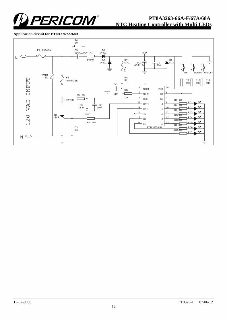
Application circuit for PT8A3267A/68A
VAR1271
D11N4007
D21N4007
R41M
LED4
LED3
LED2
LED5
VDD
D65.1V
R12 3K
R13 3K
HEATER R6 3K
R7 3K
R8 3K
LED1
LED6
R14 3K120 VAC INPUT
+EC1
47uF/10V
L
N
t
RT1NTC
RB
10K
DOWN
R10
20K
C1104
C4
333
ON/OFF
R11
20KU1
PT8A3267A/8A
GATE15
CLK3
NTC11
NCT22
L614
GND8
C15
TM4
L311
L210
L19
K27
K16
VDD16
L412
L513
UP
R5 100
R9
20K
C3104
R1
27/2W
R2 1M
R36.8k
C210nF
C5154/AC250V
F1 250V/3A
F2
TMP FUSE
LED7
R15 3K
Q1SCR
RA3K

|||||||||||||||| ||||||||||||||||||||||||||||||||||||||||||||||||||||||||||||||||||||||||||||||||||||||||||||||||||||||||||||||||||||||||||||| |||||||||||||||||||||||||||||||||||||||||||||||||||||||||||||||||||||||||||||||||||||||||||||||||||||||||||||||||||||||||||||||||||||||||||||||||||||||||||||||||||||||||||||||| ||||||||||
12-07-0006 PT0326-1 07/06/12
13
PT8A3263-66A-F/67A/68A
NTC Heating Controller with Multi LEDs
Mechanical Information
PE (DIP-16)
SYMBOL Min Max
A 3.71 4.31
A1 0.51
A2 3.20 3.60
B 0.38 0.57
B1
c 0.20 0.36
D 18.80 19.20
E 6.20 6.60
E1 7.32 7.92
e
L 3.00 3.60
E2 8.40 9.00
PKG. DIMENSIONS(MM)
1.52 BSC
2.54 BSCNote:1) Controlling dimensions in millimeters.2) Ref : JEDEC MS-001D/BB

|||||||||||||||| ||||||||||||||||||||||||||||||||||||||||||||||||||||||||||||||||||||||||||||||||||||||||||||||||||||||||||||||||||||||||||||| |||||||||||||||||||||||||||||||||||||||||||||||||||||||||||||||||||||||||||||||||||||||||||||||||||||||||||||||||||||||||||||||||||||||||||||||||||||||||||||||||||||||||||||||| ||||||||||
12-07-0006 PT0326-1 07/06/12
14
PT8A3263-66A-F/67A/68A
NTC Heating Controller with Multi LEDs
WE (SOIC-16)
SYMBOL MIN MAX
A 1.35 1.75
A1 0.10 0.25
A2 1.35 1.55
b 0.33 0.51
c 0.17 0.25
D 9.80 10.20
E 3.80 4.00
E1 5.80 6.20
e
L 0.40 1.27
θ 0° 8°
PKG. DIMENSIONS(MM)
1.27 BSC
Note:1) Controlling dimensions in millimeters.2) Ref : JEDEC MS-012E/AC

|||||||||||||||| ||||||||||||||||||||||||||||||||||||||||||||||||||||||||||||||||||||||||||||||||||||||||||||||||||||||||||||||||||||||||||||| |||||||||||||||||||||||||||||||||||||||||||||||||||||||||||||||||||||||||||||||||||||||||||||||||||||||||||||||||||||||||||||||||||||||||||||||||||||||||||||||||||||||||||||||| ||||||||||
12-07-0006 PT0326-1 07/06/12
15
PT8A3263-66A-F/67A/68A
NTC Heating Controller with Multi LEDs
Ordering Information
Ordering No. Package Code Package PT8A326xXPE P Lead free 16-pin DIP PT8A326xXWE W Lead free 16-pin SOIC PT8A3267APE P Lead free 16-pin DIP PT8A3267AWE W Lead free 16-pin SOIC PT8A3268APE P Lead free 16-pin DIP PT8A3268AWE W Lead free 16-pin SOIC
Note: “x” shows 0~4 and “X” shows A-F with different function. See Function Comparison Table.
E = Pb-free
Adding X Suffix= Tape/Reel
Function Comparison Table
P/N Temp. Levels Key Mode LED mode** Dual voltage
5 Steps 6 Steps 3-key 1-key Mode 1 Mode 2 Mode 3 Y N
3263A √ - √ - √ - - √ -
3263B √ - √ - - √ - √ -
3263C* √ - √ - - - √ √ -
3263D* √ - √ - √ - - - √
3263E* √ - √ - - √ - - √
3263F* √ - √ - - - √ - √
3264A* √ - - √ √ - - √ -
3264B* √ - - √ - √ - √ -
3264C* √ - - √ - - √ √ -
3264D* √ - - √ √ - - - √
3264E* √ - - √ - √ - - √
3264F* √ - - √ - - √ - √
3265A* - √ √ - √ - - √ -
3265B* - √ √ - - √ - √ -
3265C* - √ √ - - - √ √ -
3265D* - √ √ - √ - - - √
3265E* - √ √ - - √ - - √
3265F* - √ √ - - - √ - √
3266A* - √ - √ √ - - √ -
3266B* - √ - √ - √ - √ -
3266C* - √ - √ - - √ √ -
3266D* - √ - √ √ - - - √
3266E* - √ - √ - √ - - √
3266F* - √ - √ - - √ - √
3267A* - √ √*** - Mode 4 √ -
3268A* - √ √*** - Mode 4 √ -
Note
*: Contact Pericom for availability
**: LED mode description see Functional Description, Page 4.
***: PT8A3267A key mode is 3-key+delay+lock key(Heating off has 1s delay and lock-key function). PT8A3268A key mode
is 3-key+delay+lock-key(Heating off has 2s delay and lock-key function).
Pericom Semiconductor Corporation 1-800-435-2336 www.pericom.com Pericom reserves the right to make changes to its products or specifications at any time, without notice, in order to improve design or performance and to supply the best possible product. Pericom does not assume any responsibility for use of any circuitry described other than the circuitry embodied in Pericom product. The
company makes no representations that circuitry described herein is free from patent infringement or other rights, of Pericom.