Embed Size (px)
Citation preview

2015 SSG. All Rights Reserved.C
PSTN/GSM alarm system
User Manual
Ver.2015

Control panel layout -----------------------------------------------------------
Power on -------------------------------------------------------------------------
Connect PSTN Land Line --------------------------------------------------------- Insert a SIM Card -----------------------------------------------------------------
Control Panel Operation --------------------------------------------------------
Alarm Control -----------------------------------------------------------------
Access Control System------------------------------------------------------------
Make Phone Calls------------------------------------------------------------------
Function Setting---------------------------------------------------------------------
Table of Contents
01~02
04
0304
05~08
05~06
07
07
08
08
Voice memo ------------------------------------------------------------------
Maintenance --------------------------------------------------------------------------
FAQ ----------------------------------------------------------------------------------
Specifications --------------------------------------------------------------------
Disclaimer-----------------------------------------------------------------------------
40
41
42~43
44
Accessories ----------------------------------------------------------Remote control----------------------------------------------------------------
Door/Window Contact -------------------------------------------------------
PIR motion sensor ---------------------------------------------------------
RFID tag ----------------------------------------------------------------------------
28~3928~29
30~31
32~38
39
SMS Operation-------------------------------------------------------------------23~25
Settings --------------------------------------------------------------------------
Alarm Phone Number setting ------------------------------------------------------
Add/Delete Accessories----------------------------------------------------
System Settings ---------------------------------------------------------------
History -----------------------------------------------------------------------------
28~39
11
11~14
15~22
22
LCD Display Menu ---------------------------------------------------------------09~10
Preparation before Use ---------------------------------------------------------03~04
APP Operation-------------------------------------------------------------------26~27
Additional siren -------------------------------------------------------------------39
The system consists of a master control panel and various wire/wireless
sensors,once any unusual is detected,the alarm control panel will hoot
on-site ,meanwhile, it will send SMS to or call the preset phone numbers.
complete wireless design makes it easy to setup and install,it is widely used
in residential, commercial, industrial,personal protection, and military
properties.
System overview
Main features
GSM+PSTN dual network communicator based,more reliable
100% wireless ,easy to setup and install
Stylish design with touch keypad and LCD display
Support 30 remote controls, 99 wireless sensors, and 99 RFID tags
Can store 5 alarm phone numbers,5 SMS alert phone numbers, 2 CSM
numbers and speed dial number
Support 10s voice message recording and replay,even you can leave a
voice message from phone remotely.
Support RFID tags to disarm and unlock the electronic lock
Support maximum 150 alarm event logs
One group of timing arm and disarm
Support exit & entry delay
With password protection
4 types of zone for optional:Normal,Home,24 hours,Delay
All zones and RFID tags can be renamed
Remote control or setting by SMS,phone call and APP(iOS and Android)
SMS alert for power failure/recovery and low battery
Two-way communication to talk and hear through built-in speaker and
MIC
Nine optional display languages: English, France, German,Spanish,
Finland, Swedish, Norwegian, Danish, Italian
10 optional languages for SMS notification and APP:
English, France, German,Spanish, Finland, Swedish, Norwegian,
Danish,Italian,Chinese

Rear Side
Front Side
Control Panel LayoutTamper Switch
Speaker
Backup Batteries
Power
ON/OFF
Landline Jack
MIC
SIM Card Slot
NC Input for
Wired Sensor
(Normal Zone)
Output Wired Siren
(≤ 500mA)
Output for
Electronic Lock
AC Adapter
Jack
Terminals for
Wired Sensors
01 02
RFID Tag Reader /
Play Voice Memo
Home Mode (Part Arm)
Disarm
Arm
Voice Memo Button
LED Indicator
LCD Display
Esc
Up/Down
Enter
SOS
Clear
Call
GSM Network LED

Connect PSTN Land Line
This alarm control panel features a dual communicator of both PSTN and
GSM alarm system, If there is an alarm, it will auto dial preset phone
numbers either though landline or through GSM network.
Insert a SIM Card
Insert a GSM SIM card into the card slot according to the mark and lock it.
This step can be ignored if GSM function is not applied.
Connect the smaller connector of provided telephone cable to the
PSTN land line interface at the back side of the panel.
Connect the other end of the telephone cable to the signal output
provided by PSTN land line operator.
1.
2.
Preparation before Use
03 04
Please make sure the GSM SIM card doesn’t require any PIN code,for
more information ,please contact your local carrier.
Note:
1.Plug the AC adapter into a wall outlet
2.Plug the output connector of AC adapter into the adapter Jack of
control panel
3.Turn the power switch to on
Power on
Switch
Branch box
Control panel
TelephonePower

Control Panel Operation
Alarm Control
Arm (Away Arm)
Press the button on the [Arm ]
control panel, the system enters arm
state when one beep is heard and the
arm LED Indicator lights on.
Emergency Call
When the LCD display is activated,
Hold the button for 3 seconds [ ]
the system goes into emergent
alarming state with siren hooting,
meanwhile the panel will auto dial
pre-stored alarm phone numbers
Home Mode (Part Arm)
Press the button on [Home Mode ]
the control panel, the system enters
home mode when one beep is hear
and the home mode LED Indicator
lights on. All the normal sensor are
armed except the home mode sensors
which are disarmed, so that user can
move freely at home.
Disarm
Input user code (Default: 1234) or
admin code (Default: 123456) first
then press the button, [Disarm ]
the system enters disarm state when
one beep is heard and the disarm
LED Indicator lights on.
Note: If Entry/Exit Delay is activated, all
zones except the 24-hour zone will enter
arm state after the set delay time.
05 06
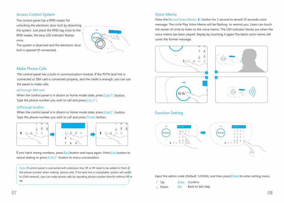
The control panel has a RFID reader for
unlocking the electronic door lock by disarming
the system. Just place the RFID tag close to the
RFID reader, the blue LED indicator flashes
once.
The system is disarmed and the electronic door
lock is opened (If connected).
Access Control System
If you input wrong numbers, press button and input again. Press button to [Esc] [Esc]
cancel dialing or press button to end a conversation.[Call ]
2
4
Function Setting
Input the admin code (Default: 123456), and then press to enter setting menu. [Enter]
Up
Down
Enter Confirm
Back to last step Esc
Note: If control panel is connected with extension line, 0# or 9# need to be added in front of
the phone number when making phone calls. if the land line is unavailable, system will switch
to GSM network, user can make phone calls by inputting phone number directly without 0# or
9#.
07 08
1
3
When the control panel is in disarm or home mode state, press button,
Type the phone number you wish to call and press . [Call ]
[Call ]
Make Phone Calls
The control panel has a built-in communication module. If the PSTN land line is
connected or SIM card is connected properly, and the credit is enough, you can use
the panel to make calls.
(a)Through SIM card
(b)Through landline
When the control panel is in disarm or home mode state, press button,
Type the phone number you wish to call and press button. [Enter]
[Call ]
Voice Memo
Press the button for 1 second to record 10 seconds voice [Record Voice Memo ]
message. The circle Play Voice Memo will be flashing to remind you. Users can touch
the center of circle to listen to the voice memo. The LED indicator blacks out when the
voice memo has been played. Replay by touching it again.The latest voice memo will
cover the former message.

09 10
In the table below,each colummn represents a menu or a sub menu,Each
menu or submebu will be displayed on on of the two lines of LCD display.On
the LCD display,the current menu,submenu or setting is shown on the line
at the bittom,while the previous menu or sub menu is shown on the line at
the top.
Navigate the select the setting you wish to modify with the keys" " or" ",
and enter each menu or sub menu by pressing " "button.Enter
How to use the touch keypad:Delete
:Down
:Up
:Confirm/select
:Back/Cancel
Main Menu Sub menu 1 Sub menu 2 Sub menu 3
Phone numbers
Accessories
Remote
Add a new
Delete all?
Delete one
*Please connect within 30s
1=YES 0=NO
Enter 01-30
RFID Tag
Add a new
Delete all?
Delete one
*Please connect within 30s
1=YES 0=NO
Enter 01-99
Wireless sensors
Add a new
Delete all?
Delete one
*Please connect within 30s
1=YES 0=NO
Enter 01-99
Test mode
System settings
Date and Time 20xx-xx-xx xx:xx
Entry Exit delayEntry delay
Exit delay
* 0-300s
* 0-300s
Auto arm/disarm
Auto arm time 00:00
Auto disarm time
On or Off
00:00
Control by phone On or Off
Line cut alarm On or Off
Keypad tones On or Off
GSM fail tip On or Off
System settings
Main Menu Sub menu 1 Sub menu 2 Sub menu 3
Access code
Admin code
User code
Duress code
Open door code
6 digits:123456
4 digits:1234
4 digits:0000
4 digits:8888
Ring time 0-9
Wired siren
Siren alert time
Built-in siren
Wireless siren
Siren setup
ON or OFF
0-9 min
ON or OFF
ON or OFF
User ID 4 digits
Arm Upload ON/OFF
Disarm Upload ON/OFF
Call recycle 0-9
Backlight time 0-300s
Reset 1=Yes 0=NO
About
Language
English,French
German,Spanish
Finnish,Swedish
Norwegian,Danish
Tialian,Chinese
History
- -
-
-
-
- -
-
-
-
-
-
-
-
-
-
-
- -
-
--1-150
Phone [1-5] is
SMS Num [1-5] is
CMS Num [1-2] is
Speed dial Num

11 12
(1)Add/delete remote&keypad
Add
a)Log on setting menu, , choose “Accessories”, press
[Enter].
b) , choose “Remote”, press .[Enter]
c) , choose “Add a new”, press .[Enter]
d)Press any button on the remote control within 30s,the control panel will
sound a beep,and the LCD will show “ ”.if the remote Add OK,Remote 01-30
already has been added before,the control panel will sound 2 beeps and
the LCD will show “ ”already exists
* When you add more remote control ,the remote control number will add 1
automatically from 01 to 30.
Delete
Delete a remote control &keypad
[Enter]a)Log on setting menu, ,choose “Accessories”, press .
b) , choose “Remote”, press . [Enter]
c) , choose “Delete one”, press .[Enter]
d)Enter the remote control number(01-30) you want to delete ,the control
panel will sound a beep if delete succeeded.
Delete all remote control&keypad
[Enter]a)Log on setting menu, ,choose “Accessories”, press .
b) , choose “Remote”, press .[Enter]
c) , choose “Delete all”, press .[Enter]
d)Enter “1” delete all the added remote control ,the control panel will sound
a beep if delete succeeded.
(2).Add/delete RFID tag
Add
b)Log on setting menu, ,choose “Accessories”, press .[Enter]
b) , choose “RFID tag”, press . [Enter]
c) , choose “Add a new”, press .[Enter]
d)Swipe the RFID tad on the RFID reader within 30s,the control panel will
sound a beep, and the LCD will show “ , RFID tag 01-50”.if the RFID Add OK
tag already has been added before ,the control panel will sound 2 beeps
and the LCD will show “ s”already exist
*When you add more RFID tags ,the RFID tag number will add 1
automatically from 01 to 50.
1. Alarm Phone Number Setting
2. Add/delete accessories
Before enter into setting menu,please disarm the system first.
Type the Admin password and then press “Enter” button on the control
panel to enter into setting menu.
Settings
Important: The default language of this alarm system is English, you can change in the
[Language] [System Setting] menu of .
User can store 5 alarm phone numbers 5 SMS alert phone numbers and 2
CMS numbers.
Add phone number
a)Log on setting menu,press ,choose “Phone Numbers”,
press .[Enter]
b) ,choose the group of phone number you want to
add, press .[Enter]
c)Input alarm phone numbers, press to save. [Enter]
Delete phone number
[Enter]a)Log on setting menu, choose “Phone Numbers”, press .
b) , choose the group of phone number you want to
delete, press .[Enter]
c)Press to delete, press to confirm.* [Enter]
or [ ] [ ]
press or [ ] [ ]
press or [ ] [ ]
press or [ ] [ ]
press or [ ] [ ]
press or [ ] [ ]
press or [ ] [ ]
press or [ ] [ ]
press or [ ] [ ]
press or [ ] [ ]
press or [ ] [ ]
press or [ ] [ ]
press or [ ] [ ]
press or [ ] [ ]press or [ ] [ ]

13 14
(3)Add/delete wireless sensors
Add
a)Log on setting menu, ,choose “Accessories”, press .[Enter]
b) , choose “wireless sensor”, press .[Enter]
c) , choose “Add a new”, press .[Enter]
d) , choose the type of sensor(Normal sensor/home
sensor/delay sensor/24 hour sensor [Enter) , press ].
e)Activate the wireless sensor within 30s,the control panel will sound a
beep ,and the LCD will show “ ”.if the wireless sensor Add OK,RFID tag 01-50
already has been added before ,the control panel will sound 2 beeps and
the LCD will show “already exists”
What is Normal Sensor/Home sensor/24 hour sensor/Delay sensor?
Normal Sensor: In arm mode, when normal sensors are triggered, system
will alarm. In disarm mode, when normal sensors are triggered, system will
not alarm.
Home Sensor: In home mode, only normal sensors will be triggered and
home sensors will not be triggered while alarming ,this will allow user to
move freely at home.
Delete
Delete a RFID tag
a)Log on setting menu, ,choose “Accessories”,press r].[Ente
b) , choose “RFID tag”, press . [Enter]
c) , choose “Delete one”, press .[Enter]
d)Enter the remote control number(01-50) you want to delete.the control
panel will sound a beep if delete succeeded.
Delete all remote control&keypad
a)Log on setting menu, choose “Accessories”, press [Enter].
b) , choose “RFID tag”, press . [Enter]
c) , choose “Delete all”, press .[Enter]
d)Enter “1” delete all the added RFID tag,the control panel will sound a
beep if delete succeeded.
(4).Test mode
Test mode enables you to check whether the remote/RFID tag/wireless
sensor has been added successfully.
a)Log on setting menu, ,choose “Accessories”, press .[Enter]
b) , choose “test mode”, press .[Enter]
c)Trigger the accessories you have added before,
24 Hour Sensor: Regardless the system is armed or disarmed, when 24 hour
sensors are triggered, system will alarm at once.
Delay Sensor: In arm mode, when delay sensors are triggered, system will
alarm after the entry delay time you have set. (please refer to the Entry
delay instruction on page 32).
*When you add more wireless sensors ,the wireless sensor number will add
1 automatically from 01 to 50.
Delete
Delete a wireless sensor
a)Log on setting menu, ,choose “Accessories”,press . [Enter]
b) , choose “wireless sensor”, press ].[Enter
c) , choose “Delete one”, press .[Enter]
d)Enter the wireless sensor number(01-50) you want to delete .the control
panel will sound a beep if delete succeeded.
Delete all wireless sensors
b)Log on setting menu, ,choose “Accessories”, press . [Enter]
b) , choose “wireless sensor”, press .[Enter]
c) , choose “Delete all”, press . [Enter]
d)Enter “1” delete all the added wireless sensor ,the control panel will
sound a beep if delete succeeded.
press or [ ] [ ]
press or [ ] [ ]
press or [ ] [ ]
press or [ ] [ ]
press or [ ] [ ]
press or [ ] [ ]
press or [ ] [ ]
press or [ ] [ ]
press or [ ] [ ]
press or [ ] [ ]
press or [ ] [ ]
press or [ ] [ ]
press or [ ] [ ]
press or [ ] [ ]
press or [ ] [ ]
press or [ ] [ ]
press or [ ] [ ]

15 16
(1)Date and Time
a)Log on setting menu, ,choose “System setting”, press
[Enter].
b) , choose “Date and Time”, press ]. [Enter
c) to move the pointer ,input current date and time,
press to save. [Enter]
(2)Entry/Exit delay
Entry delay
Entry delay gives you time to disarm the system upon entry, before an
alarm
occurs. only the delay sensors are invalid, the non delay sensors will be
triggered normally.
Log on the menu, , choose “System Settings”, press
.[Enter]
a) , choose “Entry Exit Delay”, press . [Enter]
b) , choose “Entry Delay”, press . [Enter]
c)Input time for entry delay; press to save. [Enter]
Exit delay
Exit delay gives you time to exit after arming.
a)Log on the menu, , choose “System Settings”, press
.[Enter]
b) , choose “Entry Exit Delay”, press .[Enter]
c) , choose “Exit Delay”, press . [Enter]
d)Input time for exit delay; press to save.[Enter]
*Entry/exit delay time is calculated in seconds; default is 0 second (off); the
range is 0-300 seconds.
(3)Auto Arm/Disarm
You can set up the system to arm/disarm automatically at a defined time
every day.
3.System settings Timing to Arm
a)Log on the menu, , choose “System Settings”, press
.[Enter]
b) , choose “Auto Arm/Disarm”, press .[Enter]
c) , choose “Auto Arm Time”, press .[Enter]
d)Input exact time for arming; press . [Enter]
Timing to disarm
a)log on the menu, , choose “System Settings”, press
to confirm.[Enter]
b) , choose “Auto Arm/Disarm”, press .[Enter]
c) , choose “Auto Disarm Time”, press . [Enter]
d)Input exact time for disarming; press .[Enter]
(4)Control by phone call
Method 1
When an alarm is triggered ,the control panel will dial the stored phone
numbers ,after picked up ,you can follow the voice promotion to remote
control the panel
Method 2
a) Dial the telephone number of control panel ,either the number of SIM
card in the control panel or the number of landline to which the control
panel is connected, after got through ,the voice promotion will guide you
to enter access code.
b) Enter access code(user code),press " " to confirm.#
c) Follow the voice promotion to remote control the panel.
Remote Phone Control Instruction Table
Phone
Buttons Function Explanation
Press [ ]
Press [ ]
Press [ ]
Press [ ]
Press [ ]
Arm the system
Disarm the system
Monitor on site
Turn on siren
Turn off siren
Arm succeed
Disarm succeed
Press [*] to prolong monitor time
Deter the intruders
Siren stops ringing
Press [ ] To exit Remote Phone Control Or hang up the phone
press or [ ] [ ]
press or [ ] [ ]
press or [ ] [ ]
press or [ ] [ ]
press or [ ] [ ]
press or [ ] [ ]
press or [ ] [ ]
press or [ ] [ ]
press or [ ] [ ]
press or [ ] [ ]
press or [ ] [ ]
press or [ ] [ ]
press or [ ] [ ]
press or [ ] [ ]
press or [ ] [ ]

17 18
a) Log on the menu, ,choose “System Settings”, press
[Enter].
b) , choose “Control by phone”, press .[Enter]
c) , choose “on” to turn on this function ,choose “off” to
turn off this function, press to confirm [Enter]
5)Line cut alarm
When line cut alarm function is on, the control panel will alarm once the
PSTN land line is cut or pulled out even if the built-in siren was set to mute.
Turn on/off Line cut alarm
a)Log on the menu, ,choose “System Settings”, press [Enter]
b) , choose “Line cut alarm”, press .[Enter]
c) , choose “on” to turn on this function or choose “off” to
turn off this function, press [Enter] to confirm.
6)GSM fail tip
Notification of GSM signal.
a)Log on the menu, , choose “System Settings”, press [Enter]
b) , choose “GSM fail tip”, press .[Enter]
c) , choose “on” to turn on this function or choose “off” to
turn off this function, press to confirm.[Enter]
7)Keypad Tones
Activate or deactivate the sound when typing on the keypad of control
pane
a)Log on the menu, , choose “System Settings”, press [Enter]
b) , choose “Keypad Tones”, press .[Enter]
c) , choose “on” to turn on this function or choose “off” to
turn off this function, press to confirm.[Enter]
8)Access code
The control panel has 3 types of access code, user code, admin code and
duress code. Please change all codes before using.
press or [ ] [ ]
press or [ ] [ ]
press or [ ] [ ]
Admin Code
Your admin code enables you to enter setting menu.
a)Log on the menu, ,choose “System Settings”,press .[Enter]
b) , choose “Access Code”, press .[Enter]
c) , choose “Admin Code”, press .[Enter]
d)LCD display will show “Input 6 Digits”, then input 6 digits for code, press
[Enter].
(Default Admin Code: 123456)Input the new admin code, press .[Enter]
User Code
Your user code enables you to arm/disarm the system on control panel ,and
it is the access code requested when call the alarm control panel.
a)Log on the menu, ,choose “System Settings”,press .[Enter]
b) , choose “Access Code”, press .[Enter]
c) , choose “User Code”, press .[Enter]
d)LCD display will show “Input 4 Digits”, then input 4 digits for code, press
[Enter].
(Default User Code: 1234)Input the new user code, press .[Enter]
Duress Code
In case of emergency, when user is requested to disarm the system by force,
it's recommended to use the duress code to disarm the alarm system. The
panel will silently dial the stored telephone numbers.
a)Log on the menu, ,choose “System Settings”,press .[Enter]
b) , choose “Access Code”, press .[Enter]
c) , choose “Duress Code”, press .[Enter]
d)LCD display will show “Input 4 Digits”, then input 4 digits for code, press
[Enter].
Default Duress Code: 0000)Input the new duress code, press .[Enter]
Open Door Code
This code is used to open the connected electronic lock.
a)Log on the menu, ,choose “System Settings”,press .[Enter]
b) , choose “Access Code”, press .[Enter]
press or [ ] [ ]press or [ ] [ ]
press or [ ] [ ]
press or [ ] [ ]
press or [ ] [ ]
press or [ ] [ ]
press or [ ] [ ]
press or [ ] [ ]
press or [ ] [ ]
press or [ ] [ ]
press or [ ] [ ]
press or [ ] [ ]
press or [ ] [ ]
press or [ ] [ ]
press or [ ] [ ]
press or [ ] [ ]
press or [ ] [ ]
press or [ ] [ ]
press or [ ] [ ]
press or [ ] [ ]

19 20
c) , choose “Open Door Code”, press .[Enter]
d)LCD display will show “Input 4 Digits”, then input 4 digits for code, press
[Enter].
Default Duress Code: 8888)Input the new Door Open Code, press .[Enter]
9)Ring times
This function enables you to determine the number of times the control
panel will ring before taking the phone call.
a)Log on the menu, , choose “System Settings”,press
[Enter].
b) , choose “Ring time”, press .[Enter]
c)Input 0~9,press to save[Enter]
10)Siren setup
Wired siren
Wired siren is connected to the control panel by wire.
Turn On/Off Wired Siren
a)Log on the menu, ,choose “System Settings”, press .[Enter]
b) , choose “Siren Setup”, press .[Enter]
c) , choose “Wired Siren”, press .[Enter]
d) , choose “On” or “Off” to turn the wired siren to ON or
Off, press [Enter].
Built in siren
Built in siren is inside of control panel.
Turn On/Off built in siren
a)Log on the menu, ,choose “System Settings”, press .[Enter]
b) , choose “Siren Setup”, press .[Enter]
c) , choose “Built in siren”, press .[Enter]
d) , choose “On” or “Off” to turn the built in siren to ON or
Off, press .[Enter]
press or [ ] [ ]
press or [ ] [ ]
press or [ ] [ ]
press or [ ] [ ]
Wireless siren
Wireless siren is connected to control panel through radio.
Turn On/Off wireless siren
a)Log on the menu, ,choose “System Settings”, press .[Enter]
b) , choose “Siren Setup”, press .[Enter]
c) , choose “wireless siren”, press .[Enter]
d) , choose “On” or “Off” to turn the wireless siren to ON or
Off, press .[Enter]
Set ringing time for all sirens
a)Log on the menu, ,choose “System Settings”, press [Enter]
b) , choose “Siren Setup”, press .[Enter]
c) , choose “Siren Alert Time”, press .[Enter]
d)Input the ringing time, press .[Enter]
*Siren ringing time is calculated in minutes, default setting is 3 mins ,if you
set the time to 0,the siren will not ring out.
press or [ ] [ ]
press or [ ] [ ]
press or [ ] [ ]
press or [ ] [ ]
press or [ ] [ ]
press or [ ] [ ]
press or [ ] [ ]
press or [ ] [ ]
press or [ ] [ ]
press or [ ] [ ]
press or [ ] [ ]
press or [ ] [ ]press or [ ] [ ]
press or [ ] [ ]
(11)Connect to CMS
Please ignore this step if users don't need to connect to CMS center.
This alarm control panel is full compatible with Contact ID ,when connected to
CMS center, control panel will upload contact ID to CMS center
automatically once the system is triggered.
First you sure store the CMS phone number and User ID to the alarm control
panel ,which are provided by CMS.
Please refer to the instruction of alarm phone number setting for setting the CMS
phone number.
User ID setting
a)Log on the menu; ,choose “System Settings”, press .[Enter]
b) ,choose “User ID”, press . [Enter]
c)LCD display will show “Input 4 Digits”, input 4 digits user ID, press .[Enter]
press or [ ] [ ]
press or [ ] [ ]

21 22
Upload Arm/ Disarm Report to CMS Center
When this function is enabled, all arm/disarm reports will be uploaded
automatically to CMS so that CMS center can know the status of the alarm
system.
Turn On/Off Arm/Disarm upload
a)After the User ID is set, Log on the menu; , choose “System
Settings”, press .[Enter]
b) , choose “Arm upload” or "disarm upload", press .[Enter]
c) ,choose "On" or "Off" to turn Arm/Disarm upload to On or Off.
press or [ ] [ ]
press or [ ] [ ]
press or [ ] [ ]
(12)Call recycle
The call recycle enables you to set the number of times the control panel
attempts to dails the stored alarm phone numbers.
a)Log on the menu, , choose “System Settings”, press . [Enter]
b) , choose “Call recycle”, press .[Enter]
c)Input the number[0-9], press .[Enter]
(13)Backlight time
User can set standby time of the backlight from 0 to 300s.
a)Log on the menu, ,choose “System Settings”, press .[Enter]
b) ,choose “Backlight Time”, press .[Enter]
c)Input time for backlight time; press .[Enter]
Backlight time is calculated in seconds; default is 30 seconds.
(14)Reset
a)Log on the menu, , choose “System Settings”, press .[Enter]
b) , choose “Reset”, press to reset the system to default [Enter]
setting.
Note: All system settings will be restored to default setting. Reset will not delete
the accessoriesthat has already coded to the control panel.
(15)Language
By default the language of alarm control panel is set to English.
a)Log on the menu, , choose “System Settings”, press .[Enter]
b) , choose “Language”,press [Enter]
c)Choose the language you wish to change to ,press to save.[Enter]
press or [ ] [ ]
press or [ ] [ ]
press or [ ] [ ]
press or [ ] [ ]
press or [ ] [ ]
press or [ ] [ ]
press or [ ] [ ]press or [ ] [ ]
4.History
Users can check the event logs freely,150 event logs are traceable.
a)Log on the menu, , choose “History”, press [Enter].
b) to check the event logs.
press or [ ] [ ]
press or [ ] [ ]

SMS Operation
23 24
User can send SMS command to control and configure the control panel.
Important:
1.only the stored phone number can control and configure the control panel.
2.The language of SMS command must be the same with the control panel's
language.
SMS command table
SMS command Description Reply from control panel
0 Disarm the system System disarmed
1 Arm the system System armed
2 Set the system to home mode System in home mode
3 Leave a voice message -
4 Two way communication -
00 Check the system stateSystem:xx
Power:xx
5 Store phone numbers
Phone numbers:
1.
2.
3.
4.
5.
6 Store SMS number
SMS numbers:
1.
2.
3.
4.
5.
ZONExx:-- Rename zoneNote:”xx” is the zone NO. 1-99
“--” is the zone name
RFIDxx:-- Rename RFIDNote:”xx” is the RFID tag NO. 1-50
“--”is the RFID tag name
11 Set Entry/Exit delay timeEntry delay time(0-300sec):0
Exit delay time(0-300sec):0
12 Set siren alert timeSiren volume (0 mute,1High):
Siren ringing time(1-9min):3
13 Modify disarm password Disarm password(4 digits):8888
0000 Reset system to default setting Ok
0001-0014 Change language Ok
When the control panel received the SMS command, it will reply a SMS ,the
replying of which marked in blue in the command table are the standard format,
you could edit it and resend it to control panel.
Here we give 2 examples for reference.
Store alarm phone numbers:
Send the SMS command to
control panel
Got a reply from control panel
Copy the replying, edit and resend
to control panel
If the operation succeeded,
you will get an “OK” replying

Send the SMS command to
control panel
ZONE05:Entry door sensor
25 26
Rename zone name
If the operation succeeded,
you will get an “OK” replying
Change language
Send the SMS command to
control panel
If the operation succeeded,
you will get an “OK” replying
Send the corresponding language code to control panel, then the control panel
will change to the language you want to set to. below is the code list for all
languages.
APP Operation
This system can be controlled and configured by smart phone App.
Download the APP
Search keyword “T6 alarm” in APP store or Google Play to down the App.
Launch the App, tap the add button on the bottom, then enter the name of
control panel and the SIM card number of control panel, last tap “OK” to save.
Add a control panel
You can add more control panels to the App following the steps above.
Tab this button to add
a control panel

27 28
Arm
Press the button, the system enters [Arm ]
arm state when one beep is heard and the
arm LED on the control panel is on.
Note: If Exit Delay is activated, all zones except
the 24-hour zone will enter arm state after the
set delay time.
Delete/Edit
You can swipe left the added control panel to delete or tap the control panel to edit.
Turn On/Off password
You can tap the lock button to turn On/Off the password, after that you should
enter password to logon.
Tap to turn On/Off
password
Operation guidance
1.Tap the alarm control panel you added to enter into the main page of APP ,you
can slide between the pages.
2.Under the fist page ,you can Arm ,Disarm, Home Arm the sytem ,and send a
voice memo or Two way talk request to alarm panel.
3.Under the second page ,you can program the phone number and SMS number
of alarm ,change the zones name and RFID tag notification name ,and send a
status inquiry command to alarm panel
4.Under the third page ,can you set the Entry&Exit delay time ,build-in siren
volume and ring time ,modify the disarm password ,change the language and
reset the alarm panel to factory setting.
AccssoriesRemote control
The remote control is dainty and delicate, easy to carry. It can be attached to your
key ring, or just put into your pockets or purses.When you are about to exit or entry
the house, you can use it to arm or disarm the system. In case o
the panic button, the alarm will be activated immediately.
Arm
DisarmStay
Panic
LED Indicator

The window/door sensor can be installed on doors, windows, and any other objects
that can open and close. The sensor transmits signals to the control panel when a
magnet mounted near the sensor is moved away.
LED Indication
Blinks once
Door/Window Contact
Door/Window contact is triggered
29 30
Disarm
Press the button on the remote [Disarm ]
control, the system enters disarm state when
two beeps are heard and the disarm LED on
the control panel is on.
When alarm is activated, the siren will hoot.
Press the button, the system is [Disarm ]
disarmed . But the LED indicator of triggered
zone keeps flashing for further checking.
Press button again, the alarming [Disarm ]
zone indicator goes out.
Home Arm (Part Arm)
Press button on the remote control, [Stay ]
the system enters home mode when one beep
is heard and the home mode LED is on. All the
normal sensors are armed except the home
mode sensors which are disarmed, so that
users can move freely at home.
Panic button
Whenever you press the panic button on
the remote control, the system will alarm
immediately.
LED Status Indicator
Transmitter Magnet
PCB Layout
12V 23A battery
PCB board
LED Meaning

emove the back cover
operly.
f 1 cm.
f the transmitter and magnet. Make sure the
. Make
f the transmitter. Secure the transmitter and
ed locations with double-sided tapes or screws.
operly on the desired
s when
. Purchase dedicated
logic control processing technology and intelligent
analysis algorithm, effective resolution of interfering signal and human movement
eventing false alarm. It features automatic temperature compensation
and resistance to flow technology , adapting to environmental and temperature
for halls, hallways, etc.
change. It can detect human movement within the 8-meter cone space, suitable
signal, pr
Test
Installation
PIR Motion Detector
5
4
3
LED Indication
PCB Layout
1. Press the back cover and slide down to r .
2. Remove the insulating strip. The contact works immediately.
3. Press the button on the remote control. The system switches to the arm [Arm ]
status. Separate the transmitter and magnet. The LED is on and the panel alarms. It
indicates that the sensor works pr
Note: There are triangle marks on the side o
triangle marks face each other and within the range o
Note: Make sure the transmitter and
magnet works pr
locations. If a metal door is installed,
place spacers under the transmitter
and magnet. Do not apply the contact
to a rolling shutter
contacts for rolling shutter
necessary.
Mount the transmitter on the frame and the magnet on the door or window
sure the magnet is on the right side o
magnet on the desir
The detector adopts digital
1. Detecting lens
2. LED
3. Snap joint
4. Test button
5. Installation bracket
Blinks continuously: Under self-testing state.
Blinks once: Intruder is detected.
Blinks twice: 3 minutes testing is finished, enters power saving mode.
Blinks once per 3 seconds: Low battery indication, LCD shows: Sensor 1-50(Sensor
Name) low battery, please change the batteries immediately.
Note: If the detector is disassembled,
system will sound immediately ,and
LCD shows "Sensor 1-99(Sensor
Name) Sensor Tamper".
2
1
AA
1.5
V LR
6
AA
1.5
V LR
6
LED ON / OFF Infrared sensor
Infrared sensor Zone setting
Tamper switch
31 32

s
y 10
y without
. At this
emains sleeping.
ecommended that
oom, the system alarms
Test
3. Trigger the alarm
Working Mode
Testing mode
After self-testing, the detector enter
testing mode, and detects once
every 10 seconds. After 3 minutes,
the LED blinks twice, and the
detector enters power saving mode.
Hold the test button and load the
battery, then release the test button,
the detector stands in testing mode,
it keeps detecting once ever
seconds. Exits this status by
reloading the batter
holding the test button.
Power saving mode
Press the buckle to open the back
cover. Remove the insulating strip.
After 30-second self-testing, the
detector switches to the testing mode.
1. Remove the insulating strip
Press the button on the [Arm ]
remote control. The system is in the
armed state.
2. Arm
Keep pressing the test button at the back until the siren sounds.
Note: The testing mode sustains for 3 minutes. Then, the LED blinks twice, indicating the
detector is in the power saving mode.
The product features power-saving
design. If the detector detects human
movement twice in 3 minutes, it will switch
to the sleeping state to save power
time, the LED will not blink and no alarm.
After no movement within the next 3
minutes, the detector switches back to the
working state automatically.
Sleep after detecting human movement twice
Note: After the detector is in the sleeping state,
ensure no human movement within 3 minutes;
otherwise, the detector r
In the sleeping state, it is r
you leave the room after arming the system.
Ensure no human movement in 3 minutes.
Then, go into the r
immediately.
Case 2: Press the test button and then arm.
Case 1: Initial start and then arm.
3 minutes later
No human movement within 3 minutes
Switch from sleep to arm.
33 34

Installation
2m
3. Testing
Detection Scope
2m 4m 6m 8m0m
0m
2m
110°
It is recommended to mount it at the height of 2m from the ground. (For installation
notices, please see page 21-22)
1. Choose installation place
Fix the installation bracket on the wall with screws, and then fit the groove at the back
of the detector on the bracket.
Press the test button on the back of the detector, walk in the detection scope and watch
the LED indication to make sure the detector is working.
2. Fix the detector
Adjust the bracket angle to achieve the best detection effect.
4. Adjust the bracket angle
Top view
Side view
Ground
Note: If pet-immune function is used, please do not adjust the angle up or down, but keep it
parallel with the wall.
35 36

37 38
3. Avoid facing to glass windows or doors
4. Avoid facing or positioning close to heat
5. Avoid facing to swinging objects
Swinging objects may also trigger false
triggering. Besides, if there are two
detectors covering the save scope,
adjust the locations to prevent cross-
interference.
Installation Notices
Pay attention to the following during installation:
1. Mount the detector to a location close to the entry or exit
The detector aims at preventing intrusion. Detecting human movement at the entry
or exit is critical for security.
2. Mount the detector in a proper angle
The installation angle affects sensitivity
directly. The sensitivity is optimal when
the walk direction is vertical to the
infrared direction. Choose the best
location and angle according to the
actual situation and detection scope
diagram.
Strong light interferes with detection
sensitivity. In addition, complicated
situations, such as traffic flow, stream of
people, also should be avoided.
Avoid facing or positioning close to
heat sources such as heat extraction
units, heaters, air conditioner,
microwave oven, refrigerator, which
may cause false triggering.

Maintenance
The alarm system features unique and brilliant design and craftwork. Please use it with
caution. The following suggestions will help prolong the service life of the system.
1 Keep this product and accessories out of children's reach.
2 Keep the product and accessories dry. Rainwater, moisture and liquids are likely to
contain minerals that will corrode electronic circuits.
3 Do not use or store the alarm system in dusty or dirty places; otherwise it may damage
the electronic components.
4 Do not expose the alarm system to high temperature. High temperatures can shorten
the life of electronic components, damage batteries, and cause melting and
deformation of plastic parts.
5 Do not store the alarm system in cold areas. Otherwise, when the temperature of the
alarm system rises to the normal level, moisture appears inside, damaging PCB.
6 Test the alarm system regularly and perform troubleshooting in time.
7 Check the built-in batteries of accessories regularly. If the batteries are low, replace with
new ones.
8 The alarm system requires uninterrupted power supply for working or standby.
Therefore, you need to connect the AC adapter to a reliable power outlet.
9 Avoid placing the control panel and sirens in bedrooms or offices, so as not to disturb
your rest or work.
10 It is recommended to cut off the power if the system is not used for long time.
11 If the alarm system is covered with dirt, wipe off the dirt with soft cloth or tissue. For
stains, apply diluted alkaline detergent to soft cloth, wring the cloth out and wipe the
product. Then, dry the product with dry absorbent cloth.
Please carefully read and strictly follow the previous suggestions. If the product remains
faulty, you can send it to the place of purchase or authorized maintenance center for
maintenance. We will provide help as soon as possible.
39 40
RFID tag
Additional siren
RFID tag is used to disarm your system or
unlock the electronic lock. the control panel
will send a SMS notification to the first stored
SMS phone number, when it is disarmed by
registered RFID tag. the RFID tag name
(notification content)can be defined by yourself.
The control panel already features a 100dB built in siren, it also supports wired/
wireless indoor/outdoor siren.

FAQ
Phenomena Cause of Malfunction Troubleshoot Method
No response from
control panel
operation
Accessories cannot
connect to control
panel
No response from
the control panel
by operating
remote control
Power switch is off
AC Power failure
Lithium battery backup
power exhausted
Panel not in learning
status
Accessories not triggered
for learning
The control panel has different
radio frequency with accessories
Remote control is not
learned to control panel
Open battery compartment,
turn on the power
Contact local main power
supply bureau
Connect to main power with
adapter
Make sure the panel set in
learning status
Make sure the triggered
accessories transmitting signal
to panel for learning
Follow the manual and connect
the remote control to panel
Out of range between
remote control and panel
Remote control the panel in
proper distance
Signal repeater could be added
Please contact retailer for help
RFID card/tag fail
to disarm
Touch keyboard fail
to make related
setting
RFID card/tag not connected
to the panel
Not logged onto the
setting menu
Follow the manual and connect
RFID card/tag to the panel
Input the correct admin code,
press [Enter] and log on menu
setting
No response after
inserting a SIM card
The direction of the SIM card
is not correct
Switch on the control panel
first and then insert the SIM
card
The SIM card is not a GSM
SIM card
Please insert the SIM card again
according to the user manual
Insert the SIM card first and then
switch on the control panel
Please use GSM SIM card
APP replied" Return
data run out"
Please check the network of
control panel and mobile phone
Make sure the network
works properly
APP replied "Control
panel offline"
Please check the network
of control panel
Make sure the SIM card of
control panel is not indebted
Specifications
Control Panel
Wireless Remote Control
Power Supply
Alarm Current
Transmitting Distance
Radio Frequency
Housing Material
Operating Condition
Dimensions (L x W x H)
DC 3V (CR2025 Lithium Battery x 1pc)
< 7mA
< 80m (in open area)
315MHz or 433.92MHz (± 75KHz)
ABS plastic
Temperature -10°C ~+ 55°C
Relative Humidity < 80% (non-condensing)
58 x 31 x 9.5mm
Power Supply
Standby Current
Alarm Current
Backup Battery
Internal Siren Volume
Radio Frequency
Maximum Stored Phone No.
Maximum Remote Controls
Maximum Sensors
Maximum RFID Tags
Maximum Event Logs
Housing Material
Operating Condition
Dimensions (L x W x H)
Input DC 12V 500mA, 6Wh
< 90mA
< 300mA
BL-5B 3.7V 800mAh rechargeable
lithium battery x 2 pcs
100dB
315MHz or 433.92MHz (±75KHz)
5 alarm phone numbers and 2 CMS numbers
150 events
ABS plastic
Temperature -10°C ~+55 °C
Relative Humidity < 80% (non-condensing)
203 x 117 x 25mm
41 42
30 pcs
99 pcs
99 pcs
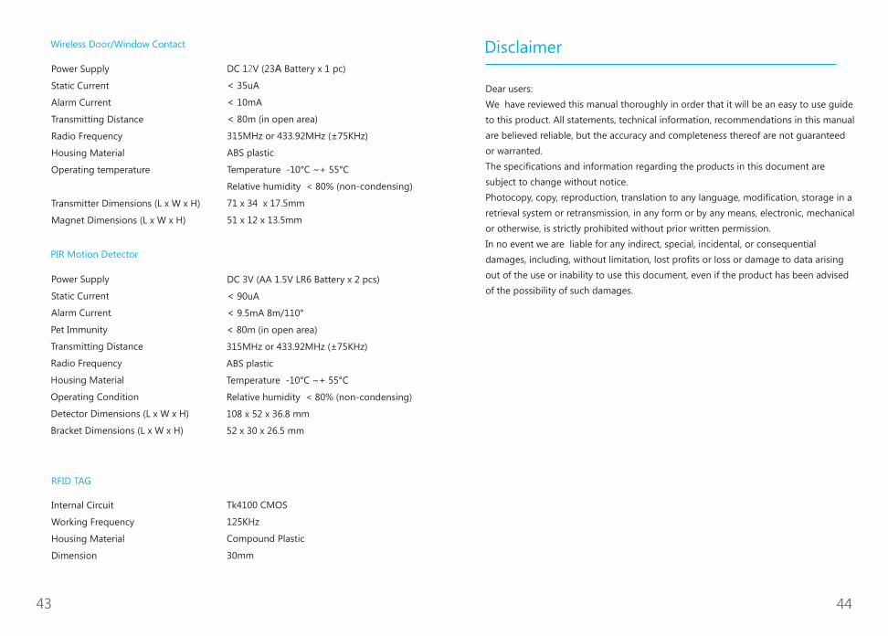
Wireless Door/Window Contact
Power Supply
Static Current
Alarm Current
Transmitting Distance
Radio Frequency
Housing Material
Operating temperature
Transmitter Dimensions (L x W x H)
Magnet Dimensions (L x W x H)
DC 12V (23A Battery x 1 pc)
< 35uA
< 10mA
< 80m (in open area)
315MHz or 433.92MHz (±75KHz)
ABS plastic
Temperature -10°C ~+ 55°C
Relative humidity < 80% (non-condensing)
71 x 34 x 17.5mm
51 x 12 x 13.5mm
Power Supply
Static Current
Alarm Current
DC 3V (AA 1.5V LR6 Battery x 2 pcs)
< 90uA
< 9.5mA 8m/110°
Pet Immunity
Transmitting Distance
Radio Frequency
Housing Material
Operating Condition
Detector Dimensions (L x W x H)
Bracket Dimensions (L x W x H)
< 80m (in open area)
315MHz or 433.92MHz (±75KHz)
ABS plastic
Temperature -10°C ~+ 55°C
Relative humidity < 80% (non-condensing)
108 x 52 x 36.8 mm
52 x 30 x 26.5 mm
RFID TAG
Internal Circuit
Working Frequency
Housing Material
Dimension
Tk4100 CMOS
125KHz
Compound Plastic
30mm
PIR Motion Detector
Dear users:
We have reviewed this manual thoroughly in order that it will be an easy to use guide
to this product. All statements, technical information, recommendations in this manual
are believed reliable, but the accuracy and completeness thereof are not guaranteed
or warranted.
The specifications and information regarding the products in this document are
subject to change without notice.
Photocopy, copy, reproduction, translation to any language, modification, storage in a
retrieval system or retransmission, in any form or by any means, electronic, mechanical
or otherwise, is strictly prohibited without prior written permission.
In no event we are liable for any indirect, special, incidental, or consequential
damages, including, without limitation, lost profits or loss or damage to data arising
out of the use or inability to use this document, even if the product has been advised
of the possibility of such damages.
Disclaimer
43 44

材料:80克书写纸
尺寸:258*185mm
工艺:双面四色印刷
装订方式:胶粘
成品尺寸:129*85mm
Designed by Henry Pien