Embed Size (px)
Citation preview

MACROTECH POLYSEAL, INC.
PSS-1000-B
MPIMPISpectraSealsSpectraSeals
PSS-1000-B
© Copyright Macrotech Polyseal, Inc. 2002

SpectraSeals are engineered plastic seals incorporating a metallic spring, which loads the seal lips against the matinghardware, creating a seal. The spring also allows the seal to follow minor eccentricity and compensates for seal lip wearin dynamic applications. SpectraSeals are normally used in single acting applications and should be oriented with thespring cavity toward the pressure side. Pressure from the media being sealed provides additional sealing force as it actsupon the sealing lips. The seal jacket is produced from a filled PTFE material or other plastic materials such as PEEK,UHMWPE, Acetal or Nylon.
SpectraSeals are typically used in applications where conventional Elastomer seals are not acceptable due to applicationconditions such as:
- Media Compatibility - Temperature Extremes (-450° to +550° F)- Friction Sensitive Applications - High Surface Speeds- Dynamic Sealing of Abrasive or Non- - High PV Rates (Pressure x Velocity)
Lubricating Media - Explosive Decompression
Application conditions determine seal material selection and seal lip style. In static or near static applications a softmaterial such as unfilled PTFE is used for optimum sealability. In dynamic applications harder materials that have betterwear resistance are recommended. Different seal lip styles are offered to address specific applications and various mediathat are sealed. This catalog will help you choose the correct seal design and materials to meet your specific applicationrequirements. If you have any questions, or would like to review your specific application with one of our DesignEngineers, please contact Macrotech Polyseal Engineering Department.
SPECTRASEAL SEALING PRINCIPLE
Seal Jacket
MetallicSpring
PressureLoad
SpringLoad
TYPICAL APPLICATIONS· Metering Pumps
· Chemical Processing Valves
· Down Hole Tools
· High Pressure Gas Compressors
· Turbo-Expanders
· Cryogenic Pumps
· Expansion Joints
· High Pressure Water orSteam Valves
· Swivel Joints
· Vapor Recovery Nozzles
· Paint Pumps
· Adhesive Pumps
· Spray Guns
· High Pressure Cleaning Equipment
· Plastic Extrusion Equipment
· Glass Processing Equipment
· Refrigeration Equipment
· HPLC (High Pressure LiquidChromatography)
· Silicone Wafer ProcessingEquipment
· Gas Turbine Engines
· Mixing Equipment
· Food Processing Equipment
· Robotics
· Machine Tools
· Mechanical Face Seals
2
W - (Helical Wound Spring/ Scraper Lip)
H - (Helical Wound Spring /Radius Lip)
X - (Cantilever Spring /Improved Scraper Lip)
S - (Cantilever Spring /Double Radius)
D - (Cantilever Spring /Scraper Lip)
B - (Cantilever Spring /Beveled Lip)
A - (Cantilever Spring /Single Radius)
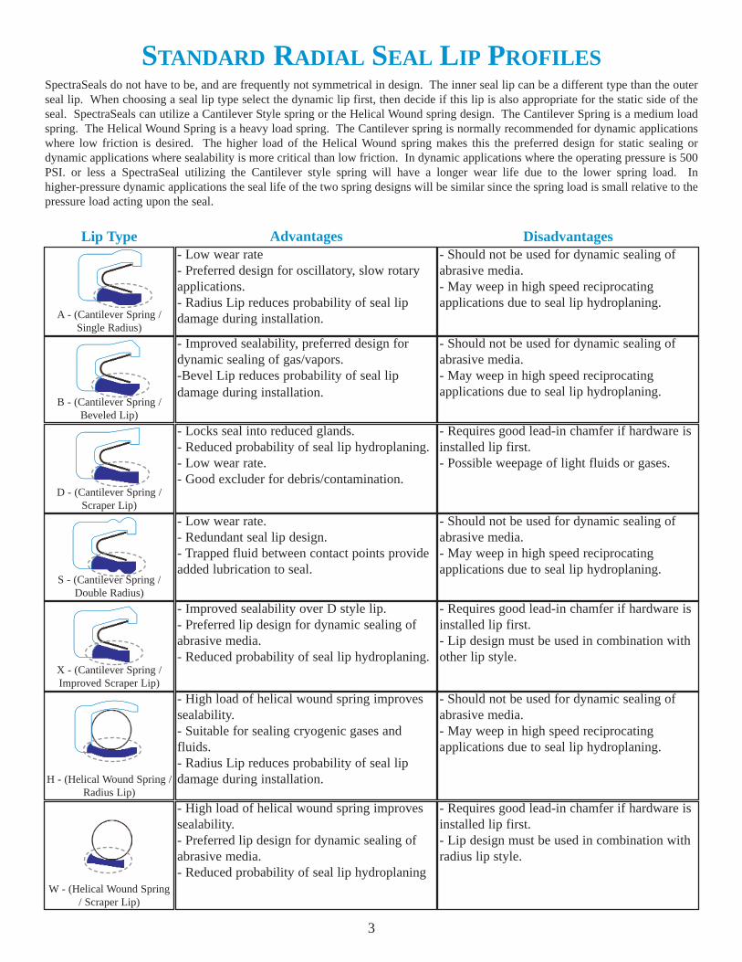
STANDARD RADIAL SEAL LIP PROFILES
- Low wear rate- Preferred design for oscillatory, slow rotary applications.- Radius Lip reduces probability of seal lip damage during installation.
- Should not be used for dynamic sealing of abrasive media.- May weep in high speed reciprocating applications due to seal lip hydroplaning.
- Improved sealability, preferred design for dynamic sealing of gas/vapors.-Bevel Lip reduces probability of seal lip damage during installation.
- Should not be used for dynamic sealing of abrasive media.- May weep in high speed reciprocating applications due to seal lip hydroplaning.
- Locks seal into reduced glands.- Reduced probability of seal lip hydroplaning.- Low wear rate.- Good excluder for debris/contamination.
- Requires good lead-in chamfer if hardware is installed lip first.- Possible weepage of light fluids or gases.
- Low wear rate.- Redundant seal lip design.- Trapped fluid between contact points provide added lubrication to seal.
- Should not be used for dynamic sealing of abrasive media.- May weep in high speed reciprocating applications due to seal lip hydroplaning.
- Improved sealability over D style lip.- Preferred lip design for dynamic sealing of abrasive media.- Reduced probability of seal lip hydroplaning.
- Requires good lead-in chamfer if hardware is installed lip first.- Lip design must be used in combination with other lip style.
- High load of helical wound spring improves sealability.- Suitable for sealing cryogenic gases and fluids.- Radius Lip reduces probability of seal lip damage during installation.
- Should not be used for dynamic sealing of abrasive media.- May weep in high speed reciprocating applications due to seal lip hydroplaning.
- High load of helical wound spring improves sealability.- Preferred lip design for dynamic sealing of abrasive media.- Reduced probability of seal lip hydroplaning
- Requires good lead-in chamfer if hardware is installed lip first.- Lip design must be used in combination with radius lip style.
Lip Type Advantages Disadvantages
3
SpectraSeals do not have to be, and are frequently not symmetrical in design. The inner seal lip can be a different type than the outerseal lip. When choosing a seal lip type select the dynamic lip first, then decide if this lip is also appropriate for the static side of theseal. SpectraSeals can utilize a Cantilever Style spring or the Helical Wound spring design. The Cantilever Spring is a medium loadspring. The Helical Wound Spring is a heavy load spring. The Cantilever spring is normally recommended for dynamic applicationswhere low friction is desired. The higher load of the Helical Wound spring makes this the preferred design for static sealing ordynamic applications where sealability is more critical than low friction. In dynamic applications where the operating pressure is 500PSI. or less a SpectraSeal utilizing the Cantilever style spring will have a longer wear life due to the lower spring load. Inhigher-pressure dynamic applications the seal life of the two spring designs will be similar since the spring load is small relative to thepressure load acting upon the seal.

STANDARD FACE SEAL DESIGNS
SPECIAL SEAL DESIGNS
EC - External FaceCantilever Spring
IC - Internal FaceCantilever Spring
IH - Internal FaceHelical Wound Spring
EH - External FaceHelical Wound Spring
O-Ring Energized
Food Service
Special Rotary
Economical Seal design but limited to the media capability andtemperature rating of the elastomer O-Ring energizer. O-Ring providesuniform load to the sealing lips and is more capable of toleratingeccentricity than springs. This design is used predominately in linearapplications where a lower friction and improved life is required overconventional elastomeric U-Cup type seals.
D Style SpectraSeal with silicone filling of spring cavity prevents foodparticles from becoming trapped in the spring cavity. Food Grade Sealsare typically produced from compound 776 (UHMWPE) or 721 (Mineralfilled PTFE). D style seal lips are recommended to minimize potentialtrapping of food particles in the seal lip area.
An O-Ring on the OD insures a tight static seal in gland and alsoprevents the seal from rotating with the shaft. Increased diametricalinterface and seal lip contact area improves wear life and the seal’sability to tolerate minor shaft bore eccentricities.
Triple Lip
Redundant seal contacts and increased load resulting from stackedCantilever Springs makes this seal especially well suited for the sealingof very viscous media such as adhesives and resins in linear applications.Should not be used in continuous rotary service due to the potential wearof the narrow contact points.
Flanged Heel
The flange on the heel prevents seal rotation in rotary applications. Thisdesign has also been used in linear applications such as metering pumpswhere it is critical that the seal not shift in the gland since the resultingvolume change could effect the accuracy of the meter.
Internal and External Face Seals can be produced using the Cantilever or Helical Wound Spring Designs. The HelicalWound Spring would be the preferred choice for static applications from Cryogenic to 550+ degrees Fahrenheit. TheCantilever Spring is typically used in low speed, rotary or oscillatory applications. Consult Macrotech PolysealEngineering Department for design recommendations for high speed rotary face sealing or dynamic sealing of abrasivemedia.
Macrotech Polyseal Engineering Department is available to review your application and recommend a seal design andmaterial to meet your specific application requirements. Special designs can normally be produced without impact to priceor availability. Below are just a few examples of non-standard designs used to meet a customers specific applicationrequirements.
4
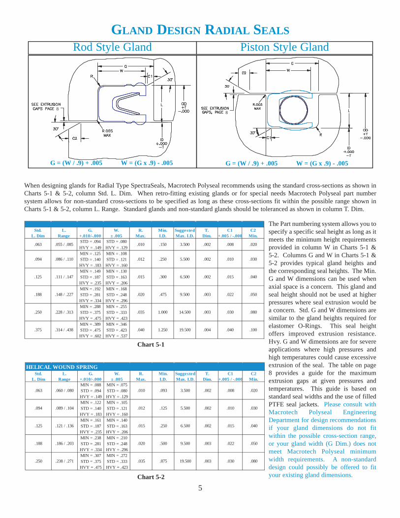
GLAND DESIGN RADIAL SEALS
Rod Style Gland Piston Style Gland
Std. L. G. W. R. Min. Suggested T. C1 C2L. Dim Range +.010/-.000 ± .005 Max. I.D. Max. I.D. Dim. +.005 / -.000 Min.
STD = .094 STD = .080
HVY = .149 HVY = .129MIN = .125 MIN = .108STD = .140 STD = .121HVY = .183 HVY = .160MIN = .149 MIN = .130STD = .187 STD = .163HVY = .235 HVY = .206MIN = .192 MIN = .168STD = .281 STD = .248HVY = .334 HVY = .296MIN = .288 MIN = .255STD = .375 STD = .333HVY = .475 HVY = .423MIN = .389 MIN = .346STD = .475 STD = .423HVY = .602 HVY = .537
.063 .055 / .085 .010 .150 3.500 .002 .008 .020
.094 .086 / .110 .012 .250 5.500 .002 .010 .030
.125 .111 / .147 .015 .300 6.500 .002 .015 .040
.188 .148 / .227 .020 .475 9.500 .003 .022 .050
.250
.375
.228 / .313
.314 / .438
.035
.040
1.000
1.250
14.500
19.500
.003
.004
.030
.040
.080
.100
Std. L. G. W. R. Min. Suggested T. C1 C2L. Dim Range +.010/-.000 ± .005 Max. I.D. Max. I.D. Dim. +.005 / -.000 Min.
MIN = .088 MIN = .075STD = .094 STD = .080HVY = .149 HVY = .129MIN = .122 MIN = .105STD = .140 STD = .121HVY = .183 HVY = .160MIN = .161 MIN = .140STD = .187 STD = .163HVY = .235 HVY = .206MIN = .238 MIN = .210STD = .281 STD = .248HVY = .334 HVY = .296MIN = .307 MIN = .272STD = .375 STD = .333HVY = .475 HVY = .423
HELICAL WOUND SPRING
.063
.094
.125
.010
.012
.015
3.500
5.500
6.500
.188
.250
.060 / .080
.089 / .104
.121 / .136
.186 / .203
.238 / .271
.020
.035
.093
.125
.250
.500
.875
9.500
19.500
.002
.002
.002
.003
.003 .030
.020
.030
.040
.050
.080
.008
.010
.015
.022
When designing glands for Radial Type SpectraSeals, Macrotech Polyseal recommends using the standard cross-sections as shown inCharts 5-1 & 5-2, column Std. L. Dim. When retro-fitting existing glands or for special needs Macrotech Polyseal part numbersystem allows for non-standard cross-sections to be specified as long as these cross-sections fit within the possible range shown inCharts 5-1 & 5-2, column L. Range. Standard glands and non-standard glands should be toleranced as shown in column T. Dim.
5
G = (W / .9) + .005 W = (G x .9) - .005 G = (W / .9) + .005 W = (G x .9) - .005
The Part numbering system allows you tospecify a specific seal height as long as itmeets the minimum height requirementsprovided in column W in Charts 5-1 &5-2. Columns G and W in Charts 5-1 &5-2 provides typical gland heights andthe corresponding seal heights. The Min.G and W dimensions can be used whenaxial space is a concern. This gland andseal height should not be used at higherpressures where seal extrusion would bea concern. Std. G and W dimensions aresimilar to the gland heights required forelastomer O-Rings. This seal heightoffers improved extrusion resistance.Hvy. G and W dimensions are for severeapplications where high pressures andhigh temperatures could cause excessiveextrusion of the seal. The table on page8 provides a guide for the maximumextrusion gaps at given pressures andtemperatures. This guide is based onstandard seal widths and the use of filledPTFE seal jackets. Please consult withMacrotech Polyseal EngineeringDepartment for design recommendationsif your gland dimensions do not fitwithin the possible cross-section range,or your gland width (G Dim.) does notmeet Macrotech Polyseal minimumwidth requirements. A non-standarddesign could possibly be offered to fityour existing gland dimensions.
Chart 5-1
Chart 5-2
88

OPTIONAL GLAND DESIGNS FOR RADIAL SEALS
Closed Gland Snap Ring Gland
Reduced Gland
There are too many possible gland configurations for us to show in this catalog. Below are a few of the more popularglands that can be used for piston or rod seals. Whenever possible the gland should be a two-piece design with generouslead-in chamfers to prevent possible damage to the sealing lips during installation.
Closed Gland - Least expensive gland to produce butrequires stretching of the seal to install in a piston typegland or distortion of the seal to install in a rod type gland.On smaller diameters it is virtually impossible to install aSpectraseal into this type of gland without damaging theseal. Consult MPI Engineering before specifying aclosed gland.
Reduced Gland - Similar to the closed gland but thesidewall on the high-pressure side of the seal has beenreduced to allow the seal to be snapped over a retention lip.A rod seal is shown but this type of gland can beincorporated for piston seals as well. It is a very positivemethod of retaining the seal, the seal cannot be removedfrom this type of gland without being destroyed. The tablebelow provides guidelines for using this type of gland. Ifthe I.D. is smaller than specified a two-piece gland or asnap ring gland should be used. If this is not possibleplease consult with Macrotech Polyseal EngineeringDepartment for other possible options.
Snap Ring - Snap Ring with retaining washer as shownreduces the possibility of seal damage during installation.Snap Ring can be used without retaining washer ifgenerous radii are incorporated into edges of the snap ringgland.
Lip Maximum MinimumHeight Radius I.D.
.063 .007 / .010 .004 .375
.094 .010 / .013 .005 .625
.125 .013 / .018 .007 .875
.188 .020 / .025 .010 1.500
.250 .023 / .028 .010 2.500
.375 .025 / .030 .012 3.500
Gland C/S
Snap Ring
Washer
6

GLAND DESIGN FACE SEALS
Internal Face External Face
7
When designing glands for Face Type SpectraSeals, Macrotech Polyseal recommends using the standard cross-sections as shown inCharts 7-1 & 7-2, column Std. L. Dim. When retro-fitting existing glands or for special needs Macrotech Polyseal part numbersystem allows for non-standard cross-sections to be specified as long as these cross-sections fit within the possible range shown inCharts 7-1 & 7-2, column L. Range. Standard glands and non-standard glands should be toleranced as shown in column T. Dim.
L DIM+U
-.000
L DIM+U
-.000
MIN
MIN
Std. L. G. W. R. Internal Face External Face Suggested T. UL. Dim Range +.010/-.000 ± .005 Max. Min. O.D. Min. I.D. Max. Dia. Dim. Dim.
STD = .094 STD = .080
HVY = .149 HVY = .129MIN = .125 MIN = .108STD = .140 STD = .121HVY = .183 HVY = .160MIN = .149 MIN = .130STD = .187 STD = .163HVY = .235 HVY = .206MIN = .192 MIN = .168STD = .281 STD = .248HVY = .334 HVY = .296MIN = .288 MIN = .255STD = .375 STD = .333HVY = .475 HVY = .423MIN = .389 MIN = .346STD = .475 STD = .423HVY = .602 HVY = .537
.004
.005
14.500
19.500
.005
.005
.035
.040
3.750
4.500
4.000
5.000
.250
.375
.228 / .313
.314 / .438
.002
.188 .148 / .227 .020 1.8751.875 9.500 .005 .003
5.500 .005 .002
.125 .111 / .147 .015 .7501.000 6.500 .005
.094 .086 / .110 .012 .625.750
.063 .055 / .085 .010 .500 3.500 .005 .002.562
Std. L. G. W. R. Internal Face External Face Suggested T. U.L. Dim Range +.010/-.000 ± .005 Max. Min. O.D. Min. I.D. Max. Dia. Dim. Dim.
MIN = .088 MIN = .075STD = .094 STD = .080HVY = .149 HVY = .129MIN = .122 MIN = .105STD = .140 STD = .121HVY = .183 HVY = .160MIN = .161 MIN = .140STD = .187 STD = .163HVY = .235 HVY = .206MIN = .238 MIN = .210STD = .281 STD = .248HVY = .334 HVY = .296MIN = .307 MIN = .272STD = .375 STD = .333HVY = .475 HVY = .423
5.500
.562
.750
1.000 .625
.035 3.000
HELICAL WOUND SPRING
.063
.094
.125
.010
.012
.015
3.500
.250
.060 / .080
.089 / .104
.121 / .136
.186 / .203
.238 / .271
1.500
6.500
.188 .020 1.500
2.500
9.500
19.500
.005
.005
.005
.005
.005
.375
.500
.004
.002
.002
.002
.003
The Part numbering system allows you tospecify a specific seal height as long as itmeets the minimum height requirementsprovided in column W in Charts 7-1 &7-2. Columns G and W in Charts 7-1 &7-2 provides typical gland heights andthe corresponding seal heights. The Min.G and W dimensions can be used whenaxial space is a concern. This gland andseal height should not be used at higherpressures where seal extrusion would bea concern. Std. G and W dimensions aresimilar to the gland heights required forelastomer O-Rings. This seal heightoffers improved extrusion resistance.Hvy. G and W dimensions are for severeapplications where high pressures andhigh temperatures could cause excessiveextrusion of the seal. The table on page8 provides a guide for the maximumextrusion gaps at given pressures andtemperatures. This guide is based onstandard seal widths and the use of filledPTFE seal jackets. Please consult withMacrotech Polyseal EngineeringDepartment for design recommendationsif your gland dimensions do not fitwithin the possible cross-section range,or your gland width (G Dim.) does notmeet Macrotech Polyseal minimumwidth requirements. A non-standarddesign could possibly be offered to fityour existing gland dimensions.
G = (W / .9) + .005
W = (G x .9) - .005
G = (W / .9) + .005
W = (G x .9) - .005
Chart 7-1
Chart 7-2
8
8

SEAL EXTRUSION
8
High pressure can cause the seal jacket material to flow into the extrusion gap in the hardware. This can result indistortion of the seal causing leakage and/or premature seal failure. Higher temperatures and dynamics increase thepossibility of extrusion. Increasing the heel thickness behind the spring will prevent extrusion in many cases. Fordemanding applications a back up ring produced from a stronger material such as Nylon, Acetal or PEEK might be usedto prevent extrusion. The table below provides the maximum recommended extrusion gaps for filled PTFE SpectraSealsat various temperatures and pressures. If your application exceeds these conditions please consult with Macrotech PolysealEngineering Department for design assistance.
Rod Seal Extrusion Use of Back Up RingIncreased Heel Thickness
Seal DegreesC/S F
To 200 .006 .005 .003 .002To 300 .005 .004 .002To 400 .004 .003To 500 .003 .002To 200 .009 .007 .004 .002 .002To 300 .008 .006 .002To 400 .007 .004 .002To 500 .005 .002To 200 .012 .010 .005 .003 .002To 300 .011 .008 .003 .002To 400 .010 .005 .002To 500 .006 .003To 200 .018 .016 .006 .004 .003 .002To 300 .017 .012 .004 .002 .002To 400 .013 .007 .002To 500 .008 .004To 200 .025 .023 .008 .005 .003 .002To 300 .023 .014 .005 .003 .002To 400 .017 .008 .003 .002To 500 .010 .005 .002
.250
3000 5000
.125
.188
Consult Macrotech Polyseal Engineering
Maximum Extrusion Gaps at VariousPressures and Temperatures
7500 10,000
.063
.093
500 psi 1000
Extrusion Gaps based on standard seal widths and the use of filled PTFEfor the seal jacket material. When using unfilled PTFE, gaps should bereduced to the next higher pressure rating.
Seal design for extreme pressures utilizing Deltatype Backup rings to bridge extrusion gap. Pressureload energizes backup rings eliminating extrusiongap. This type of Back Up Ring is frequently usedin high pressure piston applications where there is apotential of cylinder growth. Delta back up ringsare typically manufactured from high strengthplastic materials such as Nylon, Acetal or PEEK.
Pressure
Delta Back Up Rings

SURFACE FINISH REQUIREMENTS
9
SURFACE HARDNESS REQUIREMENTS
Below is a table outlining the surface finish requirements for SpectraSeals. In dynamic applications the roughness of thesurface can have a significant impact on the wear rate of the seal jacket material. Ra (Arithmetic Average RoughnessHeight) is a very commonly used measure of surface finish, but alone is not sufficient to properly specify the requiredfinish to obtain the best possible performance from a SpectraSeal. Two other valuable surface finish indicators are Rz andRsk. Rz is the average of the five greatest peak-to-valley separations. Rsk (skewness) defines the symmetry of the finishabout its mean line.
In dynamic applications it is critical that one considers the surface speed and the hardness of the mating hardware whenspecifying the seal jacket material for a SpectraSeal. Typically the more wear resistant the seal jacket material is, the moreabrasive it will be against the mating hardware. For maximum seal life at high surface speeds a heavier fill PTFE isdesired. The increased fill results in a lower wear rate but may cause wear to the mating hardware if it is not hard enough.The seal jacket materials listed on Page 10 have been coded for their abrasiveness. “A” is specified for non-abrasivematerials such as unfilled PTFE. “B” is specified for materials that should be considered slightly abrasive, while “C”represents materials that should be considered highly abrasive. Below is a chart that provides guidelines for seal jacketmaterial selection at various surface velocities and mating surface hardness.
Media Sealed Static Surface Dynamic SurfaceCryogenic and Ra 6-12 µin
Critical Sealing
of Light Gasses
Less Critical
Gas Sealing
Rz < 50 µin
Rsk -1.0 to - 4.0
Ra 2-8 µin
Rz < 30 µin
Rsk -1.0 to -4.0
Ra 16-32 µin
Rz < 80 µin
Rsk -1.0 to - 4.0
Ra 6-12 µin
Rz < 50 µin
Rsk -1.0 to -4.0
Ra 8-16 µin
Rz < 50 µin
Rsk -1.0 to -4.0
Fluid Sealing Ra 20-63 µin
Rz < 80 µin
Rsk -1.0 to - 4.0
A or B A, B or C A, B or C
A A or B A, B or C
A A or B A or B
Velocity Feet
0-50
51-100
101 +
Rockwell Hardness
< 30 RC 45 RC 58 RC/ Minute Consult Macrotech Polyseal Engineering for recommendations
for rotary sealing at speeds greater than 300 feet per minute.

SPECTRALOY
COMPOUND #
-450 Unfilled PTFE: Used predominately for static or slow speed/intermittent dynamic+450 service. Excellent for cryogenic service.-450 15% Graphite filled PTFE: Very low coefficient of friction. Used in low-pressure+500 dynamic applications that are friction sensitive.-450 *Ekonol® filled PTFE: Good wear resistance but is not abrasive against non-+550 hardened surfaces. Should not be used in steam applications.-450 Polyimide filled PTFE: Excellent wear resistance but is not abrasive against non-+550 hardened surfaces. Should not be used in steam applications.-450 Mineral, Moly filled PTFE: Excellent wear resistance. Typically used for dynamic+550 sealing at higher temperatures and pressures.-450 Mineral filled PTFE: Filler is an FDA approved mineral. Used for sealing food+550 products at temperatures greater than 180° Fahrenheit.-450 10% Carbon Graphite filled PTFE: General-purpose material. Suitable for dynamic+550 sealing of steam and water.-450 Glass, Moly filled PTFE: Excellent material for dynamic sealing at high+550 temperatures and pressures.-450 PPS, Carbon and Moly filled PTFE: Excellent wear rate in non-lubricated service+550 at high temperatures and pressures.
Carbon Fiber filled PTFE: Excellent wear and creep resistance at elevatedtemperatures. Good abrasion resistance for sealing non-lubricating media at
+550 elevated temperatures.-450 25% Carbon Graphite filled PTFE: Similar to #734 but additional filler improves+550 wear, creep and extrusion resistance.-450 40% Bronze filled PTFE: Suited for high-speed dynamic sealing of lubricating media.+550 Should not be used for Chemical service.
UHMWPE: FDA and USDA approved. Best material for reciprocating service inwater or water based fluids. Typically used for food products, paints, adhesives
+180 and resins. Excellent abrasion resistance.-100 Unfilled PEEK: High strength material predominately used for back-up rings.+550 Suitable for sealing non-lubricating, viscous fluids from ambient to 550ºF.
700
716
771
721
711
741
755
756
734
702
745
P E
E G
G G
G E
703
A
F E A
B
G G B
A
E G A
E E C
B
E E C
E E C
E P B
A
G G B
Material Comparison: E = Excellent G = Good F = Fair P = Poor
782 E E C-450
-450776 E G
TEMP.
RATING (º
F)
WEAR R
ESISTANCE
CHEMIC
ALRESIS
TANCE
MATIN
G SURFA
CEHARDNESS
(See
Tab
le on
Pag
e 9)
SEALABILITY
EXTRUSION
RESISTANCE
COMPOUND FEATURES ANDRECOMMENDED SERVICE
STANDARD SPRING MATERIAL
Spring Type 301 Stainless 17-7 PH Stainless *Elgiloy
Cantilever
Helical Wound
Spring Materials
* While Stainless Steel 301 and 17-7 PH are suitable for most applications, *Elgiloy®, which is a Cobalt Nickel Alloy, isa premium grade material. This material offers improved load deflection and chemical resistance. Elgiloy meets therequirements of NACE (National Association Of Corrosion Engineers).
10
SEAL JACKET COMPOUNDS
The materials below are some of the more common materials used in SpectraSeals. Macrotech Polyseal has numerousother compounds available, if one of these standard compounds fails to meet your application requirements.
*Elgiloy is a registered trade mark of Elgiloy Limited Partnership. All rights reserved.*Ekonol is a registered trade mark of Carborundum Company. All rights reserved.

SPECTRASEAL PART NUMBERING SYSTEM
XB125 - 02500 - 160 - A - 776
I.D. Lip StyleO.D. Lip Style(See StandardLip Profiles)
Gland Cross-Section (L Dim.)
Nominal Gland I.D.
Seal Height(W Dim.)
Spring MaterialA - SS 301 Cantilever SpringB - Elgiloy Cantilever SpringC - 17-7PH Helical Wound SpringD - Elgiloy Helical Wound Spring
Seal Jacket Compounds(See Page 10)
11
A-Style LipSingle Radius Lip
B-Style LipBeveled Lip
D-Style LipScraper Lip
S-Style LipDouble Radius
X-Style LipImproved Scraper
Lip
H-Style HelicalWound/Radius Lip
W-Style HelicalWound/Scraper Lip
IC-Internal FaceCantilever Spring
EC-External FaceCantilever Spring
EH-External FaceHelical Wound
Spring
IH-Internal FaceHelical Wound
Spring
IH125 - 02500 - 160 - C - 776I = Internal FaceE = External Face
H = Helical Wound SpringC = Cantilever Spring
Gland Cross-Section (L Dim.)
Nominal Gland I.D. for External Face Seals.Nominal Gland O.D. for Internal Face Seals.
Seal Height(W Dim.)
Spring MaterialA - SS 301 Cantilever SpringB - Elgiloy Cantilever SpringC - 17-7PH Helical Wound SpringD - Elgiloy Helical Wound Spring
Seal Jacket Compounds(See Page 10)
Radial Seal Part Numbering System
Face Seal Part Numbering System

IMPORTANT NOTICE
We reserve the right to make changes without notice in our products and in theinformation and content of this brochure. The statements and information inthe brochure are intended to serve only as guides. There are no warranties or
binding descriptions of the products.
NOTICE OF EXCLUSIVE WARRANTY AND REMEDY
Briefly, our exclusive warranty is against defects in materials and workman-ship at the time of shipment. It is in lieu of all other warranties. There is noimplied warranty of merchantability or fitness for a particular purpose. The
exclusive remedy is replacement of defective products or, at our option, refundof their purchase price. All damages exceeding the purchase price are exclud-ed, whether consequential or otherwise and regardless of cause. The terms andconditions on our printed quotation contain a much more complete statement
of our Exclusive Warranty and Remedy.
MACROTECH POLYSEAL, INC.
P.O. Box 26627 Salt Lake City, UT 84126(801) 973-9171 (800) 453-8742Fax (801) 973-9188 (800) 825-7325
Visit us on the Internet atwww.polyseal.com
Authorized MPI Distributor:
2002 MACROTECH POLYSEAL, INC. Rev. #PSS1000-B