Embed Size (px)
Citation preview

R08DS0204EJ0100 Rev.1.00 Page 1 of 12 Dec 25, 2020
Data Sheet
PS2503-1, PS2503L-1
LOW INPUT CURRENT, HIGH SPEED SWITCHING
DESCRIPTION
The PS2503-1 and PS2503L-1 are optically coupled isolator containing a GaAs light emitting diode and an NPN silicon phototransistor. The PS2503-1 is in a plastic DIP (Dual In-line Package) and the PS2503L-1 is lead bending type (Gull-wing) for surface mount.
FEATURES
High isolation voltage (BV = 5 000 Vr.m.s.) High-speed switching (tr = 20 s TYP., tf = 30 s TYP.) Ordering number of taping product: PS2503L-1-F3 : 2 000 pcs/reel Pb-Free product Safety standards
UL approved: UL1577, Double protection CSA approved: CAN/CSA-C22.2 No. 62368-1, Reinforced insulation
APPLICATIONS
Measurement equipment Programmable logic controller Telephone/Telegraph Receiver Power supply
R08DS0204EJ0100Rev.1.00
Dec 25, 2020
PIN CONNECTION(Top View)
1. Anode2. Cathode3. Emitter4. Collector
1 2
4 3

PS2503-1, PS2503L-1
R08DS0204EJ0100 Rev.1.00 Page 2 of 12 Dec 25, 2020
PACKAGE DIMENSIONS (UNIT: mm)
DIP Type
Lead Bending Type For Surface Mount
Weight ( 4-pin DIP):0.26 g (typ.)
PHOTOCOUPLER CONSTRUCTION
Parameter PS2503-1, PS2503L-1
Air Distance (MIN.) 7 mm
Creepage Distance (MIN.) 7 mm
Isolation Distance (MIN.) 0.3 mm
PS2503-1
3.5
±0.
3
4.15
±0.
43
.2±
0.4
2.54
1.25±0.150.50±0.10
0.25 M
4.6±0.35
6.5±
0.5
0 to 15°
7.62
0.25 +0.1 –0.05
1 2
4 3
PS2503L-1
0.25 M
4.6±0.35
6.5
±0
.53
.5±
0.3
2.54
1.25±0.15 0.9±0.25
9.60±0.4
0.2
5+
0.1
–0
.05
0.1
+0
.1 –
0.0
5
1 2
4 3
0.15

PS2503-1, PS2503L-1
R08DS0204EJ0100 Rev.1.00 Page 3 of 12 Dec 25, 2020
MARKING EXAMPLE
ORDERING INFORMATION
Part Number Order Number *1 Solder Plating
Specification
Packing Style Safety Standard
Approval
Application Part
Number *2
PS2503-1 PS2503-1-A Pb-Free Magazine case 100 pcs Standard products
(UL, CSA approved) PS2503-1
PS2503L-1 PS2503L-1-A PS2503L-1
PS2503L-1-F3 PS2503L-1-F3-A Embossed Tape 2 000 pcs/reel PS2503L-1
Notes: *1. When specifying CTR rank, please add “/CTR rank” after Order Number.
ex. L rank : PS2503-1-A/L
Notes: *2. For the application of the Safety Standard, following part number should be used.
No. 1 pinMark
Made in Japan
JPb-Free
Assembly Lot
Company Initial
Type Number
R
Week AssembledYear Assembled (Last 1 Digit)
In-house Code
CTR Rank Code
NJ0312503
N J 0 31

PS2503-1, PS2503L-1
R08DS0204EJ0100 Rev.1.00 Page 4 of 12 Dec 25, 2020
ABSOLUTE MAXIMUM RATINGS (TA = 25 C, unless otherwise specified)
Parameter Symbol Ratings Unit
Diode Reverse Voltage VR 6 V
Forward Current (DC) IF 80 mA
Power Dissipation Derating PD/C 1.5 mW/C
Power Dissipation PD 150 mW
Peak Forward Current*1 IFP 1 A
Transistor Collector to Emitter Voltage VCEO 40 V
Emitter to Collector Voltage VECO 0.6 V
Collector Current IC 30 mA
Power Dissipation Derating PC/C 1.5 mW/C
Power Dissipation PC 150 mW
Isolation Voltage*2 BV 5 000 Vr.m.s.
Operating Ambient Temperature TA –55 to +100 C
Storage Temperature Tstg –55 to +150 C
Note: *1. PW = 100 s, Duty Cycle = 1 %
*2. AC voltage for 1 minute at TA = 25 C, RH = 60 % between input and output.
Pins 1-2 shorted together, 3-4 shorted together.

PS2503-1, PS2503L-1
R08DS0204EJ0100 Rev.1.00 Page 5 of 12 Dec 25, 2020
ELECTRICAL CHARACTERISTICS (TA = 25 C)
Parameter Symbol Conditions MIN. TYP. MAX. Unit
Diode Forward Voltage VF IF = 1 mA 1.1 1.3 V
Reverse Current IR VR = 5 V 5
Terminal Capacitance Ct V = 0 V, f = 1.0 MHz 50 pF
Transistor Collector to Emitter Dark Current
ICEO VCE = 40 V, IF = 0 mA 100 nA
Coupled Current Transfer Ratio (IC/IF)
CTR IF = 1 mA, VCE = 5 V 100 200 400 %
Collector Saturation Voltage
VCE (sat) IF = 1 mA, IC = 0.2 mA 0.25 V
Isolation Resistance RI-O VI-O = 1.0 kVDC 1011
Isolation Capacitance CI-O V = 0 V, f = 1.0 MHz 0.5 pF
Rise Time*2 tr VCC = 5 V, IF = 1 mA, RL = 10 k 20 s
Fall Time*2 tf 20
Note: *1. CTR rank K : 200 to 400 (%)
L : 150 to 300 (%)
M : 100 to 200 (%)
*2. Test Circuit for Switching Time
VCC
VOUT
RL = 10 k50
PW = 100 sDuty Cycle = 1/10
Pulse InputIF
Input
Output
90%
10%tr
td
tf
tston toff

PS2503-1, PS2503L-1
R08DS0204EJ0100 Rev.1.00 Page 6 of 12 Dec 25, 2020
TYPICAL CHARACTERISTICS (TA = 25 C, unless otherwise specified)
Remark The graphs indicate nominal characteristics.
150
100
50
0 25 50 75 100 125 150
1.5 mW/°C
150
100
50
25 50 100 125 1500
1.5 mW/°C
100
1.51.41.31.21.11.00.90.80.7
50
10
5
1
0.5
0.1
Dio
de
Po
we
r D
issi
pat
ion
PD (
mW
)
Tran
sist
or
Po
we
r D
issi
pat
ion
PC (
mW
)
Ambient Temperature TA (°C)
Forw
ard
Cu
rren
t I
F (m
A)
Forward Voltage V F (V)
Co
lle
cto
r to
Em
itte
r D
ark
Cu
rre
nt
IC
EO (
nA
)
Collector Saturation Voltage V CE (sat) (V)
Ambient Temperature TA (°C)
Ambient Temperature TA (°C)
DIODE POWER DISSIPATION vs.AMBIENT TEMPERATURE
TRANSISTOR POWER DISSIPATIONvs. AMBIENT TEMPERATURE
FORWARD CURRENT vs.FORWARD VOLTAGE
COLLECTOR TO EMITTER DARKCURRENT vs. AMBIENT TEMPERATURE
COLLECTOR CURRENT vs.COLLECTOR SATURATION VOLTAGE
Co
llect
or
Cu
rre
nt
IC (m
A)
75
Co
llect
or
Cu
rre
nt
IC (
mA
)
Collector to Emitter Voltage VCE (V)
COLLECTOR CURRENT vs.COLLECTOR TO EMITTER VOLTAGE
–55 °C
0 °C–25 °C
+60 °C+25 °C
TA = +100 °C
12
2
10
8
6
4
2
0 4 6 8 10
IF = 0.6 mA0.8 mA
1 mA
1.5 mA
2 mA
3 mA
4 mA5 mA
100
50
10
1.0
0.3
5.0
VCE = 40 V30 V20 V10 V
–25 0 25 50 75 100
10
1.00.80.60.40.20
5
1
0.5
0.1
30
IF = 0.8 mA
1 mA
2 mA
5 mA
10 mA

PS2503-1, PS2503L-1
R08DS0204EJ0100 Rev.1.00 Page 7 of 12 Dec 25, 2020
Remark The graphs indicate nominal characteristics.
Normalized to 1.0at TA = 25 °C,IF = 1 mA, VCE = 5 V
Forward Current I F (mA)Ambient Temperature TA (°C)
Ambient Temperature TA (°C)
Frequency f (Hz)
No
rmal
ized
Cu
rre
nt
Tra
nsf
er
Rat
io C
TR
Cu
rren
t Tr
ansf
er R
atio
CTR
(%)
No
rmal
ize
dG
ain
GV
Load Resistance R L (Ω)
Sw
itch
ing
Tim
e t
(
s)
μNORMALIZED CURRENT TRANSFERRATIO vs. AMBIENT TEMPERATURE
CURRENT TRANSFER RATIO vs.FORWARD CURRENT
SWITCHING TIME vs.AMBIENT TEMPERATURE
SWITCHING TIME vs.LOAD RESISTANCE
FREQUENCY RESPONSE
Sw
itch
ing
Tim
e t
(
s)
1.4
1.2
1.0
0.8
0.6
0.4
0.2
010050 75250–30
400
300
200
100
00.3 0.5 1 5 10 50 100
500
100
50
10
5
11007550250–25–50
tr
CTR = 290 %,VCC = 5 V,IF = 1 mA,
RL = 10 kΩ
ts
tf
td
50
10
5
1
0.1
0.5
100 k50 k10 k5 k1 k500100
IF = 1 mA, VCC = 5 V,CTR = 209 %,
tr
td
tf
ts IF VCC
VO
RL50 Ω
0
–3.0
–6.0
–9.0
–12.0
–15.0
100 1 k 10 k 100 k 1 M
VCC = 5 V,CTR = 209 %
RL = 5.6 kΩ 1 kΩ 300 Ω
Sample ABC
VCE = 5 V
μ
PS2503-1, PS2503L-1
R08DS0204EJ0100 Rev.1.00 Page 8 of 12 Dec 25, 2020
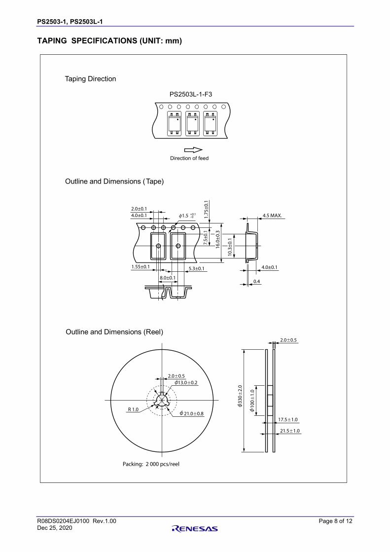
TAPING SPECIFICATIONS (UNIT: mm)
PS2561DL-1-F3
1.55±0.1
2.0±0.1
4.0±0.1 1.7
5±
0.1
4.5 MAX.
4.0±0.1
0.4
5.3±0.1
8.0±0.1
7.5±
0.1
16.
0±0
.3
10
.3±
0.1
1.5 +0.1–0
Packing: 2 000 pcs/reel
2.0±0.5
R 1.0
13.0±0.2
21.0±0.8
330
±2
.0
100
±1
.0
2.0±0.5
21.5±1.0
17.5±1.0
Taping Direction
Outline and Dimensions (Tape)
Direction of feed
Outline and Dimensions (Reel)
PS2503L-1-F3

PS2503-1, PS2503L-1
R08DS0204EJ0100 Rev.1.00 Page 9 of 12 Dec 25, 2020
RECOMMENDED MOUNT PAD DIMENSIONS (UNIT: mm)
Remark All dimensions in this figure must be evaluated before use.
PS2503L
D
C
B
A
Part Number Lead Bending A
Lead Bending Type For Surface Mount 8.2
B
2.54
C
1.7
D
2.2

PS2503-1, PS2503L-1
R08DS0204EJ0100 Rev.1.00 Page 10 of 12 Dec 25, 2020
NOTES ON HANDLING
1. Recommended soldering conditions (1) Infrared reflow soldering
• Peak reflow temperature 260 C or below (package surface temperature) • Time of peak reflow temperature 10 seconds or less • Time of temperature higher than 220C 60 seconds or less • Time to preheat temperature from 120 to 180C 120 30 s • Number of reflows Three • Flux Rosin flux containing small amount of chlorine
(The flux with a maximum chlorine content of 0.2 Wt% is recommended.)
(2) Wave soldering • Temperature 260 C or below (molten solder temperature) • Time 10 seconds or less • Preheating conditions 120 C or below (package surface temperature) • Number of times One (Allowed to be dipped in solder including plastic mold portion.) • Flux Rosin flux containing small amount of chlorine (The flux with a maximum
chlorine content of 0.2 Wt% is recommended.)
(3) Soldering by Soldering Iron • Peak Temperature (lead part temperature) 350 C or below • Time (each pins) 3 seconds or less • Flux Rosin flux containing small amount of chlorine
(The flux with a maximum chlorine content of 0.2 Wt% is recommended.)
(a) Soldering of leads should be made at the point 1.5 to 2.0 mm from the root of the lead (b) Please be sure that the temperature of the package would not be heated over 100 C
(4) Cautions
• Flux Cleaning Avoid cleaning with Freon based or halogen-based (chlorinated etc.) solvents.
• Do not use fixing agents or coatings containing halogen-based substances.
120 ± 30 s(preheating)
220 °C
180 °C
Pac
kag
e S
urf
ace
Te
mp
era
ture
T (
°C)
Time (s)
Recommended Temperature Profile of Infrared Reflow
(heating)to 10 s
to 60 s
260 °C MAX.
120 °C

PS2503-1, PS2503L-1
R08DS0204EJ0100 Rev.1.00 Page 11 of 12 Dec 25, 2020
2. Cautions regarding noise Be aware that when voltage is applied suddenly between the photocoupler’s input and output or between collector-emitters at startup, the output transistor may enter the on state, even if the voltage is within the absolute maximum ratings.
3. Measurement conditions of current transfer ratios (CTR), which differ according to photocoupler Check the setting values before use, since the forward current conditions at CTR measurement differ according to product.
When using products other than at the specified forward current, the characteristics curves may differ
from the standard curves due to CTR value variations or the like. Therefore, check the characteristics
under the actual operating conditions and thoroughly take variations or the like into consideration before
use.
USAGE CAUTIONS
1. Protect against static electricity when handling. 2. Avoid storage at a high temperature and high humidity. 3. Avoid cleaning with Freon based or halogen-based (chlorinated etc.) solvents. 4. Do not use fixing agents or coatings containing halogen-based substances.

PS2503-1, PS2503L-1
R08DS0204EJ0100 Rev.1.00 Page 12 of 12 Dec 25, 2020
Caution GaAs Products This product uses gallium arsenide (GaAs). GaAs vapor and powder are hazardous to human health if inhaled or ingested, so please observe the following points.
• Follow related laws and ordinances when disposing of the product. If there are no applicable laws and/or ordinances, dispose of the product as recommended below.
1. Commission a disposal company able to (with a license to) collect, transport and dispose of materials that contain arsenic and other such industrial waste materials.
2. Exclude the product from general industrial waste and household garbage, and ensure that the product is controlled (as industrial waste subject to special control) up until final disposal.
• Do not burn, destroy, cut, crush, or chemically dissolve the product.
• Do not lick the product or i any way allow it to enter the mouth.
All trademarks and registered trademarks are the property of their respective owners.

http://www.renesas.comRefer to "http://www.renesas.com/" for the latest and detailed information.
Renesas Electronics CorporationTOYOSU FORESIA, 3-2-24 Toyosu, Koto-ku, Tokyo 135-0061, JapanRenesas Electronics America Inc.1001 Murphy Ranch Road, Milpitas, CA 95035, U.S.A.Tel: +1-408-432-8888, Fax: +1-408-434-5351Renesas Electronics Canada Limited9251 Yonge Street, Suite 8309 Richmond Hill, Ontario Canada L4C 9T3Tel: +1-905-237-2004Renesas Electronics Europe GmbHArcadiastrasse 10, 40472 Düsseldorf, GermanyTel: +49-211-6503-0, Fax: +49-211-6503-1327Renesas Electronics (China) Co., Ltd.Room 101-T01, Floor 1, Building 7, Yard No. 7, 8th Street, Shangdi, Haidian District, Beijing 100085, ChinaTel: +86-10-8235-1155, Fax: +86-10-8235-7679Renesas Electronics (Shanghai) Co., Ltd.Unit 301, Tower A, Central Towers, 555 Langao Road, Putuo District, Shanghai 200333, ChinaTel: +86-21-2226-0888, Fax: +86-21-2226-0999Renesas Electronics Hong Kong LimitedUnit 1601-1611, 16/F., Tower 2, Grand Century Place, 193 Prince Edward Road West, Mongkok, Kowloon, Hong KongTel: +852-2265-6688, Fax: +852 2886-9022Renesas Electronics Taiwan Co., Ltd.13F, No. 363, Fu Shing North Road, Taipei 10543, TaiwanTel: +886-2-8175-9600, Fax: +886 2-8175-9670Renesas Electronics Singapore Pte. Ltd.80 Bendemeer Road, Unit #06-02 Hyflux Innovation Centre, Singapore 339949Tel: +65-6213-0200, Fax: +65-6213-0300Renesas Electronics Malaysia Sdn.Bhd.Unit No 3A-1 Level 3A Tower 8 UOA Business Park, No 1 Jalan Pengaturcara U1/51A, Seksyen U1, 40150 Shah Alam, Selangor, MalaysiaTel: +60-3-5022-1288, Fax: +60-3-5022-1290Renesas Electronics India Pvt. Ltd.No.777C, 100 Feet Road, HAL 2nd Stage, Indiranagar, Bangalore 560 038, IndiaTel: +91-80-67208700Renesas Electronics Korea Co., Ltd.17F, KAMCO Yangjae Tower, 262, Gangnam-daero, Gangnam-gu, Seoul, 06265 KoreaTel: +82-2-558-3737, Fax: +82-2-558-5338
SALES OFFICES
© 2019 Renesas Electronics Corporation. All rights reserved.Colophon 8.0
(Rev.4.0-1 November 2017)
Notice1. Descriptions of circuits, software and other related information in this document are provided only to illustrate the operation of semiconductor products and application examples. You are fully responsible for
the incorporation or any other use of the circuits, software, and information in the design of your product or system. Renesas Electronics disclaims any and all liability for any losses and damages incurred by
you or third parties arising from the use of these circuits, software, or information.
2. Renesas Electronics hereby expressly disclaims any warranties against and liability for infringement or any other claims involving patents, copyrights, or other intellectual property rights of third parties, by or
arising from the use of Renesas Electronics products or technical information described in this document, including but not limited to, the product data, drawings, charts, programs, algorithms, and application
examples.
3. No license, express, implied or otherwise, is granted hereby under any patents, copyrights or other intellectual property rights of Renesas Electronics or others.
4. You shall not alter, modify, copy, or reverse engineer any Renesas Electronics product, whether in whole or in part. Renesas Electronics disclaims any and all liability for any losses or damages incurred by
you or third parties arising from such alteration, modification, copying or reverse engineering.
5. Renesas Electronics products are classified according to the following two quality grades: “Standard” and “High Quality”. The intended applications for each Renesas Electronics product depends on the
product’s quality grade, as indicated below.
"Standard": Computers; office equipment; communications equipment; test and measurement equipment; audio and visual equipment; home electronic appliances; machine tools; personal electronic
equipment; industrial robots; etc.
"High Quality": Transportation equipment (automobiles, trains, ships, etc.); traffic control (traffic lights); large-scale communication equipment; key financial terminal systems; safety control equipment; etc.
Unless expressly designated as a high reliability product or a product for harsh environments in a Renesas Electronics data sheet or other Renesas Electronics document, Renesas Electronics products are
not intended or authorized for use in products or systems that may pose a direct threat to human life or bodily injury (artificial life support devices or systems; surgical implantations; etc.), or may cause
serious property damage (space system; undersea repeaters; nuclear power control systems; aircraft control systems; key plant systems; military equipment; etc.). Renesas Electronics disclaims any and all
liability for any damages or losses incurred by you or any third parties arising from the use of any Renesas Electronics product that is inconsistent with any Renesas Electronics data sheet, user’s manual or
other Renesas Electronics document.
6. When using Renesas Electronics products, refer to the latest product information (data sheets, user’s manuals, application notes, “General Notes for Handling and Using Semiconductor Devices” in the
reliability handbook, etc.), and ensure that usage conditions are within the ranges specified by Renesas Electronics with respect to maximum ratings, operating power supply voltage range, heat dissipation
characteristics, installation, etc. Renesas Electronics disclaims any and all liability for any malfunctions, failure or accident arising out of the use of Renesas Electronics products outside of such specified
ranges.
7. Although Renesas Electronics endeavors to improve the quality and reliability of Renesas Electronics products, semiconductor products have specific characteristics, such as the occurrence of failure at a
certain rate and malfunctions under certain use conditions. Unless designated as a high reliability product or a product for harsh environments in a Renesas Electronics data sheet or other Renesas
Electronics document, Renesas Electronics products are not subject to radiation resistance design. You are responsible for implementing safety measures to guard against the possibility of bodily injury, injury
or damage caused by fire, and/or danger to the public in the event of a failure or malfunction of Renesas Electronics products, such as safety design for hardware and software, including but not limited to
redundancy, fire control and malfunction prevention, appropriate treatment for aging degradation or any other appropriate measures. Because the evaluation of microcomputer software alone is very difficult
and impractical, you are responsible for evaluating the safety of the final products or systems manufactured by you.
8. Please contact a Renesas Electronics sales office for details as to environmental matters such as the environmental compatibility of each Renesas Electronics product. You are responsible for carefully and
sufficiently investigating applicable laws and regulations that regulate the inclusion or use of controlled substances, including without limitation, the EU RoHS Directive, and using Renesas Electronics
products in compliance with all these applicable laws and regulations. Renesas Electronics disclaims any and all liability for damages or losses occurring as a result of your noncompliance with applicable
laws and regulations.
9. Renesas Electronics products and technologies shall not be used for or incorporated into any products or systems whose manufacture, use, or sale is prohibited under any applicable domestic or foreign laws
or regulations. You shall comply with any applicable export control laws and regulations promulgated and administered by the governments of any countries asserting jurisdiction over the parties or
transactions.
10. It is the responsibility of the buyer or distributor of Renesas Electronics products, or any other party who distributes, disposes of, or otherwise sells or transfers the product to a third party, to notify such third
party in advance of the contents and conditions set forth in this document.
11. This document shall not be reprinted, reproduced or duplicated in any form, in whole or in part, without prior written consent of Renesas Electronics.
12. Please contact a Renesas Electronics sales office if you have any questions regarding the information contained in this document or Renesas Electronics products.
(Note 1) “Renesas Electronics” as used in this document means Renesas Electronics Corporation and also includes its directly or indirectly controlled subsidiaries.
(Note 2) “Renesas Electronics product(s)” means any product developed or manufactured by or for Renesas Electronics.