Embed Size (px)
DESCRIPTION
A weld feature is a parametrically defined feature in the Pro/E model, similar to chamfers or holes, etc. By defining a set of relevant criteria in the 3D model, the weld feature becomes part of the solid model. The feature appears in the model tree and may be reordered and hidden or displayed just like other features. The appearance of the weld and the associated weld symbol may also be controlled to suit the user.
Citation preview
Table of Contents
Introduction..........................................................................................................................3What is a weld feature & why should I use it?................................................................3If this is so good, why hasn’t anyone used it before?......................................................4
Weld Features in Pro/E........................................................................................................6Weld Feature Capabilities in Pro/E Wildfire 5:...............................................................6Weld Feature Limitations in Wildfire 5:.........................................................................7
General Workflow...............................................................................................................8User Interface (Wildfire 5)................................................................................................11Weld Symbols & Drawings...............................................................................................17
Parametric Weld Symbols:............................................................................................17Non-parametric Weld Symbols.....................................................................................19
Controlling Weld Display..................................................................................................19Weld Symbol Display in Models...................................................................................19Surface & Light Weld Geometry Types........................................................................20Standard Color For Welds.............................................................................................22Suggested Layer Usage..................................................................................................23Suggested Layer Usage For Weld Features in Drawings..............................................26
Mass Property Calculations of Weld Features...................................................................27Weld Info...........................................................................................................................30Weld Modeling Strategies.................................................................................................40
When should the weld feature be defined?....................................................................40What is Edge Prep and should it be used?.....................................................................40What are Weld Notches and should I use them?...........................................................42At which level should the weld feature be included?....................................................43Can welds be patterned? Should they be patterned?.....................................................43Are there other options for duplicating weld features?.................................................44When should similar welds be combined?....................................................................45How should tack welds be handled?..............................................................................47How should surface welds be handled?.........................................................................48
1
Pro/E Wildfire 5 Weld Features:Best Practices Guide
December 2009

Case Studies.......................................................................................................................49Continuous Weld Joints Spanning Gaps Between Plates..............................................49Using Weld Features in Pro/MECHANICA..................................................................51Modifying Weld Start/End Points.................................................................................52Creating Intermittent Welds..........................................................................................56Modeling Complex Weld Joints....................................................................................61Associative Cross Sectional Weld Area........................................................................64Combining Similar Welds.............................................................................................65Tail Welds......................................................................................................................66Modeling Slot Welds.....................................................................................................68
Downstream Usage............................................................................................................70Programmatic Data Exchanges......................................................................................70User-Defined Data Exchanges.......................................................................................70Future Directions For Downstream Usage....................................................................75
Appendices........................................................................................................................76Appendix A: Weld-related config.pro options..............................................................76Appendix B: Welding Parameters.................................................................................78Appendix C: Suggested Weld Preferences Settings......................................................79Appendix D: Suggested Layer Rules.............................................................................82
2

Introduction
What is a weld feature & why should I use it?
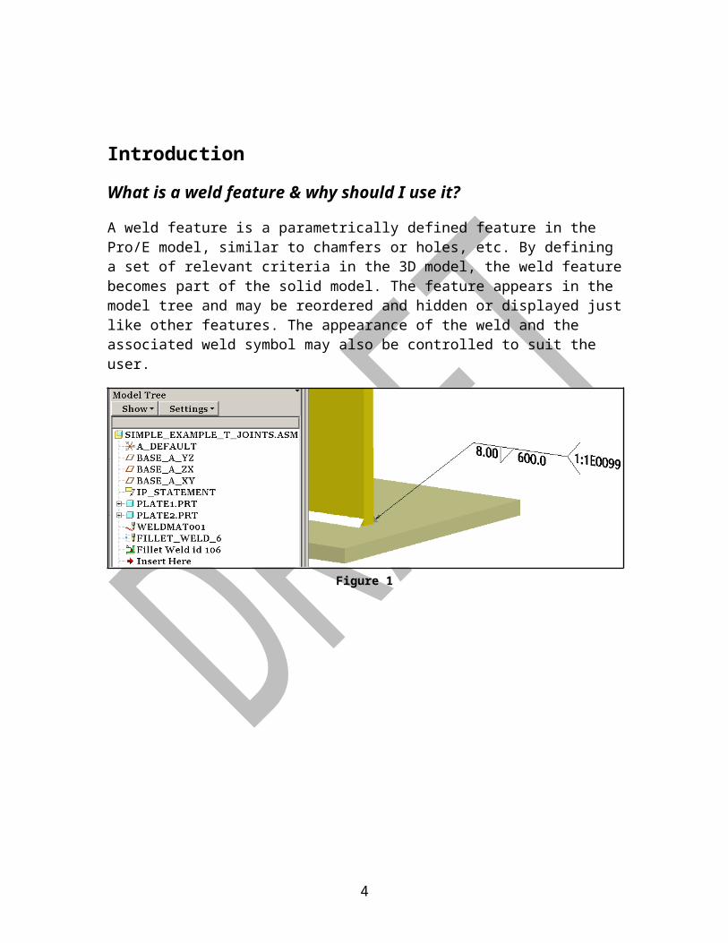
A weld feature is a parametrically defined feature in the Pro/E model, similar to chamfers or holes, etc. By defining a set of relevant criteria in the 3D model, the weld feature becomes part of the solid model. The feature appears in the model tree and may be reordered and hidden or displayed just like other features. The appearance of the weld and the associated weld symbol may also be controlled to suit the user.
Figure 1
For many years, the most common means to define and communicate information about weld joints in the design and manufacture of a fabricated structure has consisted of using a standard set of weld symbols placed on a 2D drawing. These symbols are used by people trained to interpret these symbols to communicate details such as weld joint type, size, location, etc.
Figure 2
3
There are a couple of problems associated with that system. Weld symbol ‘standards’ vary from one company to the next, so when working with suppliers that must provide a service for more than one customer, there can potentially be misinterpretation of these drawing symbols.
Another frequent problem is finding all of the welds in a complex drawing. It is not uncommon for multiple drawing changes to be made just to ensure all welds are accounted for.
With the weld represented by a 2D drawing symbol rather than actual geometry in the model, it is possible to define welds that are too large to fit within the space allowable in the design. This can result in poor fit-up during assembly.
In other cases, this lack of visualization of the welded joint in the model may contribute to accessibility issues for both manual and robot welding operations.
Finally, 2-D drawings are normally completed later in the design cycle. This causes delays in all subsequent tasks. If the welds were defined as the design is being developed, this information could be utilized in a variety of downstream applications, resulting in a condensed NPI cycle, assuming the definition of these weld features was fast and easy.
If this is so good, why hasn’t anyone used it before?
The weld feature capability in Pro/ENGINEER was first introduced back in the mid 1990’s, however the functionality was limited, thus it attracted very little interest from a user community that was generally content with continuing the practice of communicating design intent with 2D drawings. Since the tool was basically sitting there unused, the developers had no incentive to improve it. They also had no clear direction on how it should be improved to make it a production design tool. As years passed, and new versions of Pro/E were released, the core modeling part of the software saw huge productivity improvements, making the Pro/WELD module even less appealing than ever by comparison.
Another factor in the lack of usage of the weld features in the CAD models was the performance of computer hardware and software. In the earlier years, users jumped through all sorts of hoops to minimize the amount of data that had to be processed and displayed to the screen. Culling out “non-essential” information that was already being communicated with 2D drawings was a necessary evil. But improvements to both hardware technology and software algorithms have greatly reduced the need to be so judicious with the information contained in a design model. It is no longer necessary to dumb down the model in order to provide for efficient display repaints and model regenerations.
4

Finally, to make matters worse, the Pro/WELD module was marketed as an additional module, meaning that the customer had to pay extra for the rights to use that tool. Not only was the expense of ownership an issue, but setting up node-locked licenses was a hidden cost. In 2006 Caterpillar worked out a new software license agreement with PTC, which in effect lumped all of these additional modules in with the core tools, removing that added expense and hassle of serving the licenses to users.
When Pro/WELD was thrown into the bucket of Pro/E software that was immediately available to all users at Caterpillar, there was a renewed interest in the potential benefits of defining welds as parametric features in the CAD models. A couple of pilot projects were initiated to test out the capability that existed in the current version of the software (Wildfire 2) and to generate a list of requirements that would need to be fulfilled before the application was considered a viable alternative to the old practice of defining and communicating weld joints on the 2D drawings. A corporate team then followed up on this enhancement request list with the software developer (see TIC letter ASRP: Improved Weld Definition in CAD Models, DN1053721,2007 for further information) and worked with them to implement these changes.
The whole weld feature definition capability was rewritten for Wildfire 5. This purpose of this document is intended to clarify the best practices for getting started with the usage of Pro/E weld features for Caterpillar engineers.
5

Weld Features in Pro/E
Weld Feature Capabilities in Pro/E Wildfire 5:
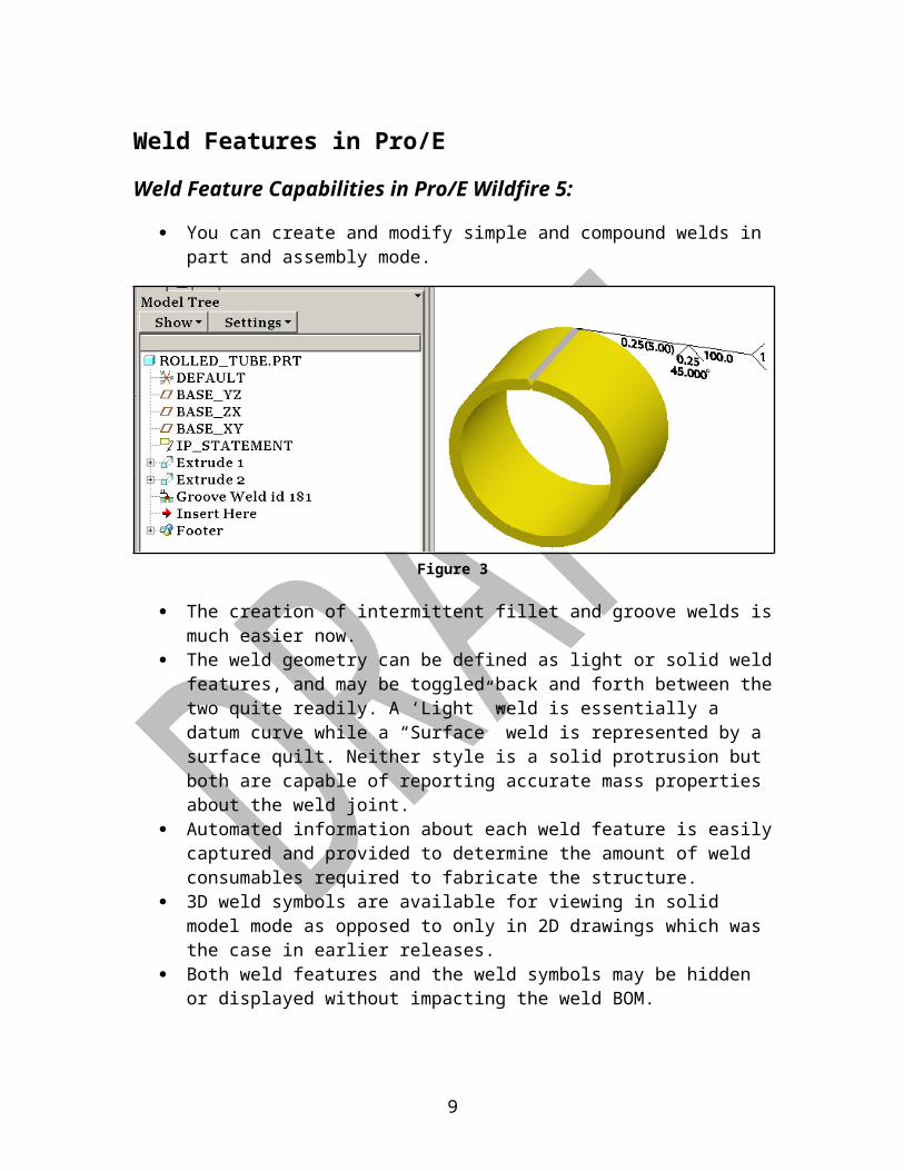
You can create and modify simple and compound welds in part and assembly mode.
Figure 3
The creation of intermittent fillet and groove welds is much easier now. The weld geometry can be defined as light or solid weld features, and may
be toggled back and forth between the two quite readily. A ‘Light” weld is essentially a datum curve while a “Surface” weld is represented by a surface quilt. Neither style is a solid protrusion but both are capable of reporting accurate mass properties about the weld joint.
Automated information about each weld feature is easily captured and provided to determine the amount of weld consumables required to fabricate the structure.
3D weld symbols are available for viewing in solid model mode as opposed to only in 2D drawings which was the case in earlier releases.
Both weld features and the weld symbols may be hidden or displayed without impacting the weld BOM.
Weld features can include pre-loaded system parameters such as Finish and Contour, as well as user-defined parameters.
Libraries of weld processes may be developed and assigned to the weld features. These processes can include such things as wire feed rates, pre-weld and post-weld treatments, etc.
Libraries of weld consumables can also be developed and assigned to the weld features, helping to provide more precise mass property information of welded structures.
6

Libraries of customized (1E0099 compliant) weld symbols that are parametrically driven by the weld features may be developed and shown automatically in 3D and 2D mode.
Parametric weld symbols may also be shown in the 2D drawings. Multiple welds of a similar design can be combined into a single symbol.
The weld feature is recognized and may be utilized by Pro/MECHANICA, making it easier to set up models for analysis runs.
Weld Feature Limitations in Wildfire 5: SOLID protrusions of weld joints do not yet exist. You can get visual
representations of the weld joints and all mass properties of the weld joints are available, but it is not possible to use the weld joint geometry in FEA, and a weld feature still cannot be intersected with a cut feature.
Weld volume and mass are still an approximation – not exact. They provide a far more accurate value than the typical estimation of a given percentage of the structure mass, but weld cross-sectional area can vary through the length of the joint and in Wildfire 5, a uniform weld cross-sectional area is used to calculate the volume of the weld joint.
The ability to quickly flex a weld joint between the bounds of the weld size tolerance (LMC and MMC) does not yet exist.
There is no tack weld or surface weld capability yet. Workaround techniques are provided in the Weld Modeling Strategies section of this guide.
7

General WorkflowNow that you know what you can and cannot do with respect to weld feature definition in Wildfire 5 let’s take a look at the general sequence of tasks required for the creation of new weld features.
There are several things that can be done upfront to initialize default settings for weld features, much like in standard Pro/E. These defaults are then used every time you create a new weld feature. It is not required that these default settings be defined prior to the design session, but it does help to speed up the feature creation and also helps to ensure a more consistent and complete feature definition.
Prior to the actual weld feature creation:1. Define and save the preferences and defaults to a library directory.
2. Locate the preference files in your configuration file so that Pro/E knows where to look for the default settings.
There will be more detailed discussion on those two tasks later in this guide. The first two steps only need to be done once. You might possibly add new preference files or modify existing ones, but generally speaking this setup work needs to be done one time only.
The steps required to build a weld feature are listed below. Most of these steps will be described in greater detail later in this guide.
3. Open a part or an assembly.
4. Change the Application to Welding mode.
5. Define the welding environment by defining welding materials, processes, preferences, and parameters. As noted earlier, much of this can be set up to be defined by default in the config.pro file. If you need to override that, then you can change the material or the processes and that will be modal
8
Note: In the current build of Wildfire 5, this task actually needs to be performed whenever the first weld feature in a model is defined. Pro/E ignores the lines in the config.pro file that defines where these files are found. This problem has been reported as a software performance report #7381244. We anticipate that this problem will be resolved in a future build of Wildfire 5.
– it won’t change for the rest of the session unless you change it. The next time you restart Pro/E, it will revert back to whatever your configuration file defines for default values.1
6. Select the type of weld feature to create on the model (fillet weld, spot weld , etc).
7. Determine if you want to weld, prepare edges, or create weld notches, or a combination of the three. In most cases, we will define edge prep and notches as common cut or chamfer features in the part or assembly model, so normally the only thing to really worry about is the actual weld feature.
8. Determine the family table configuration. The family table provides the functionality to create the cut in either the generic model or instances of the model. It is recommended not to use the family table function for welds at this time.
9. Select geometry on the model that describes the weld location. This can be model surfaces, or edges, or curves, etc, depending on which type of weld you want to create.
10. Determine if you want your weld to contain surface or light geometry. Again, this can be set up initially in the config.pro file, or it can be changed with preference settings. Or, you can change it from one geometry type to the other during the weld feature definition.
11. Define the weld dimensions. This includes the shape of the weld cross-section as well as any start/end offset dimensions. If defining an intermittent weld, you will have additional information to complete to describe the segment length and pitch between segments.
12. Choose the desired weld cross-section type. If your config option WELD_ASK_XSEC_REFS is set to YES, you will not be able to complete the weld feature until you define a plane for the weld cross-section, or you must change from By Reference to By Value in the Weld Cross section window.
1 As noted earlier, problems have been documented with this functionality. Until this problem is resolved, you will need to initialize the weld material type and preferences each time you begin to define weld features in a model. If the weld material already exists in the model, either from an existing weld feature or due to having been saved with weld materials already assigned, then you should be able to proceed normally.
9

13. Assign Weld Material and a Weld Process. Neither of these two components of the weld feature is absolutely essential – you can complete a weld feature successfully without either of these. But if you define a weld material, you can then get mass properties for the weld feature and if you define a process you can get additional weld process parameters defined and attached to that weld feature. In theory, you could get welding time from this; however there appears to be more work that needs to be done before this value is considered useful. Once again, the weld processes can be predefined in library settings so there could be default values for both Material and Process if desired.
14. Add any notes that you may want included in the tail of the weld symbol annotation. These are notes are part of the actual weld symbol annotation – not a separate annotation.
15. Assign any additional parameters if desired.
16. After completing the welds for the part or assembly you may re-order the sequence of the welds as desired.
17. You can also generate either a bill of materials (BOM) or Pro/REPORT tables with weld parameters or both.
10

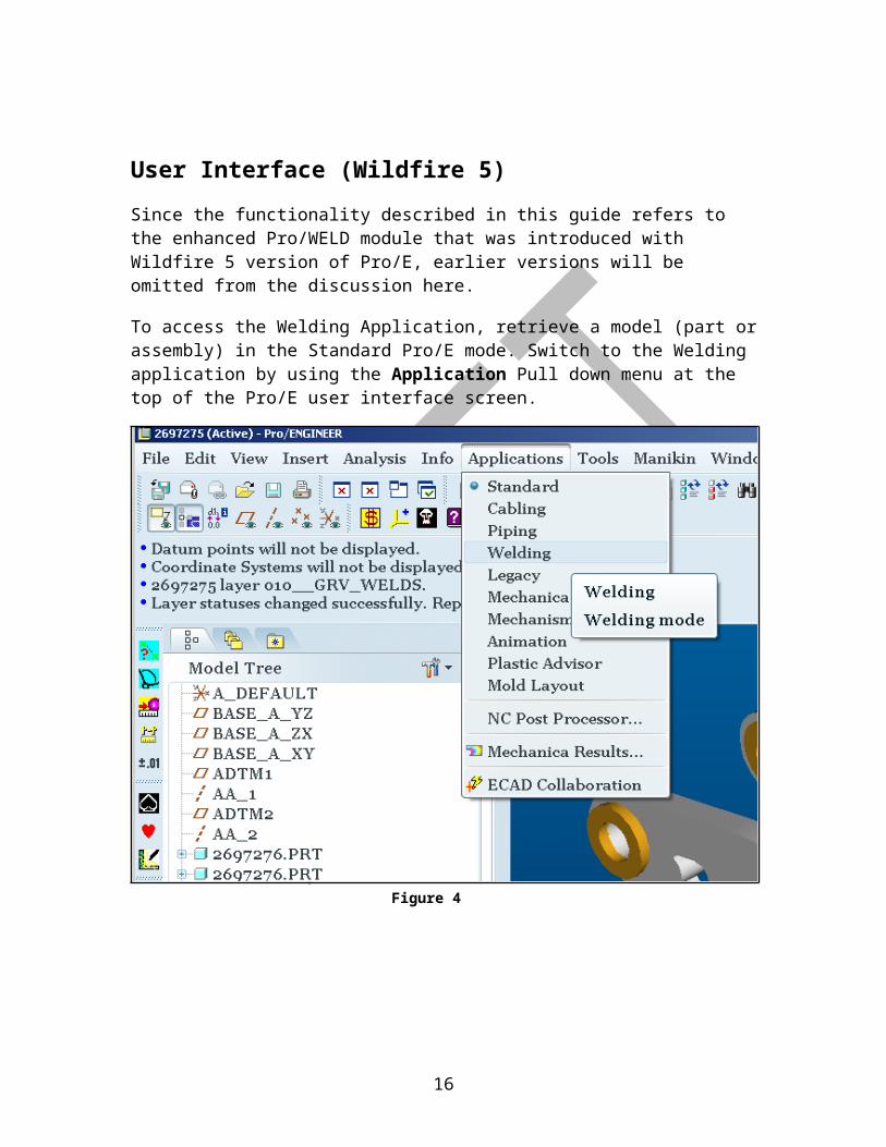
User Interface (Wildfire 5)
Since the functionality described in this guide refers to the enhanced Pro/WELD module that was introduced with Wildfire 5 version of Pro/E, earlier versions will be omitted from the discussion here.
To access the Welding Application, retrieve a model (part or assembly) in the Standard Pro/E mode. Switch to the Welding application by using the Application Pull down menu at the top of the Pro/E user interface screen.
Figure 4
11
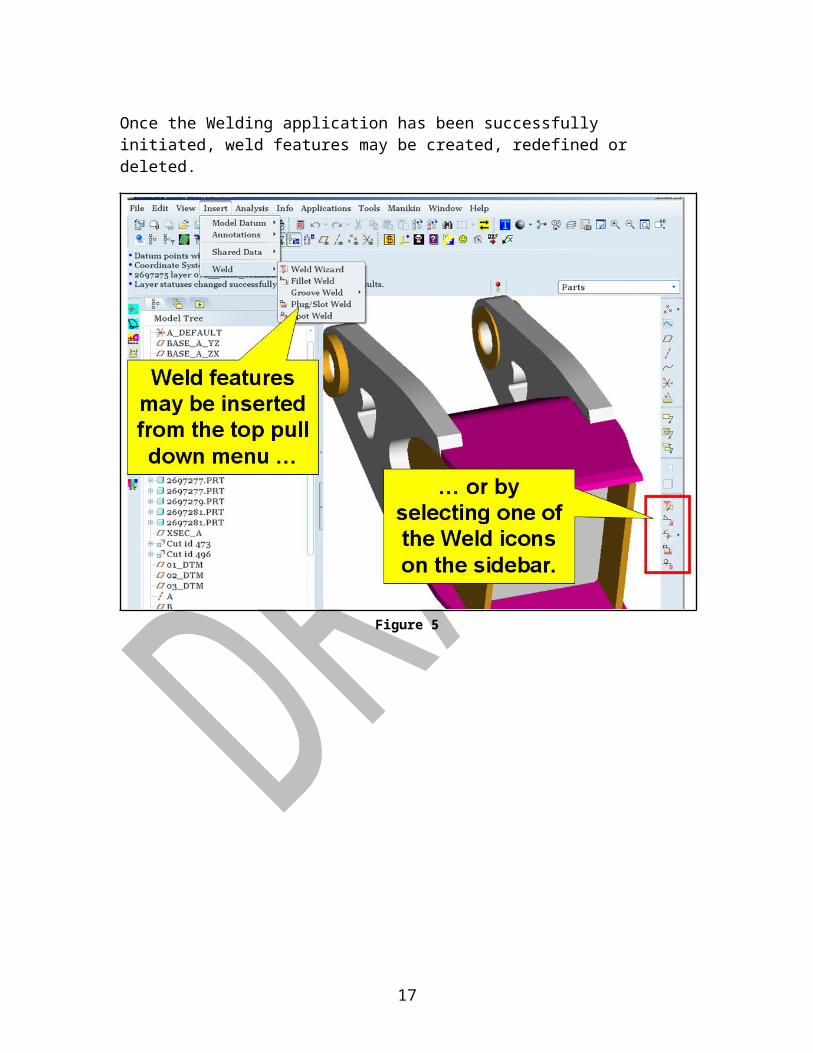
Once the Welding application has been successfully initiated, weld features may be created, redefined or deleted.
Figure 5
12
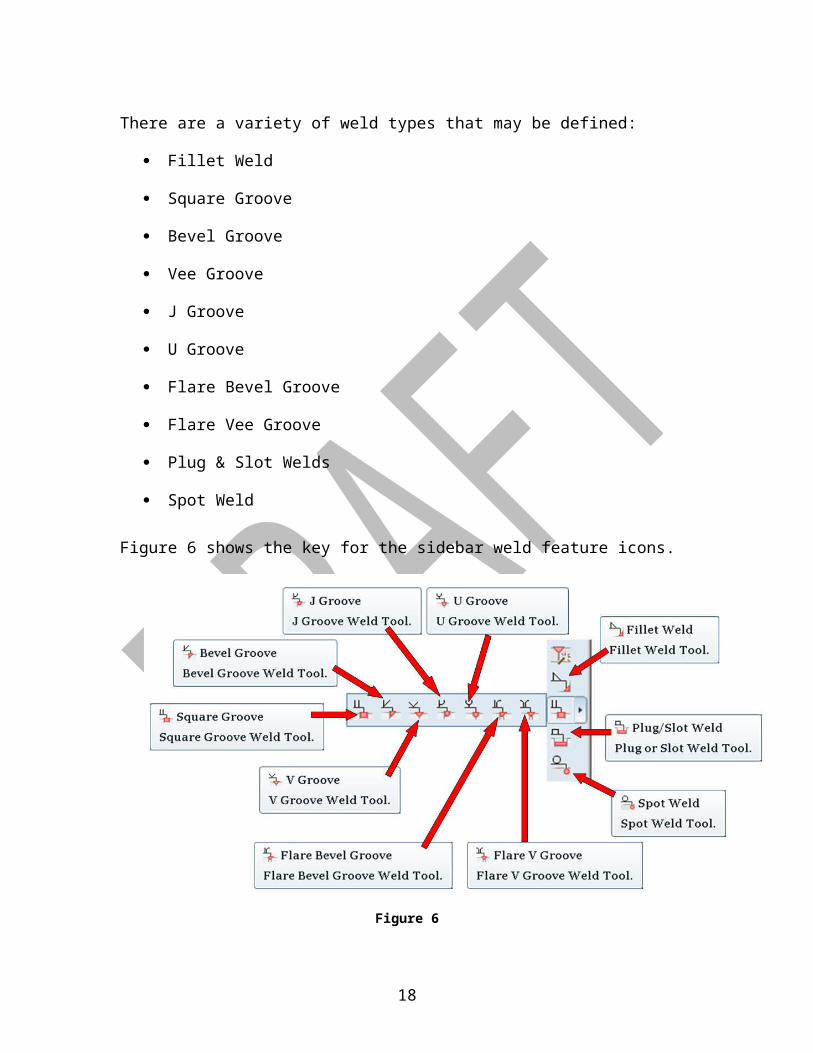
There are a variety of weld types that may be defined:
Fillet Weld
Square Groove
Bevel Groove
Vee Groove
J Groove
U Groove
Flare Bevel Groove
Flare Vee Groove
Plug & Slot Welds
Spot Weld
Figure 6 shows the key for the sidebar weld feature icons.
Figure 6
13
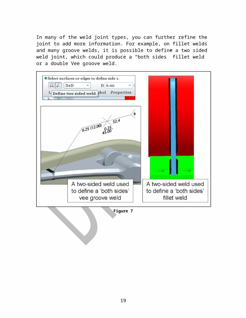
In many of the weld joint types, you can further refine the joint to add more information. For example, on fillet welds and many groove welds, it is possible to define a two sided weld joint, which could produce a “both sides” fillet weld or a double Vee groove weld.
Figure 7
14
It is also possible to further refine a fillet or groove weld joint to be an intermittent weld.
Figure 8
For additional information on defining intermittent welds, see the ‘Case Studies’ section of this guide.
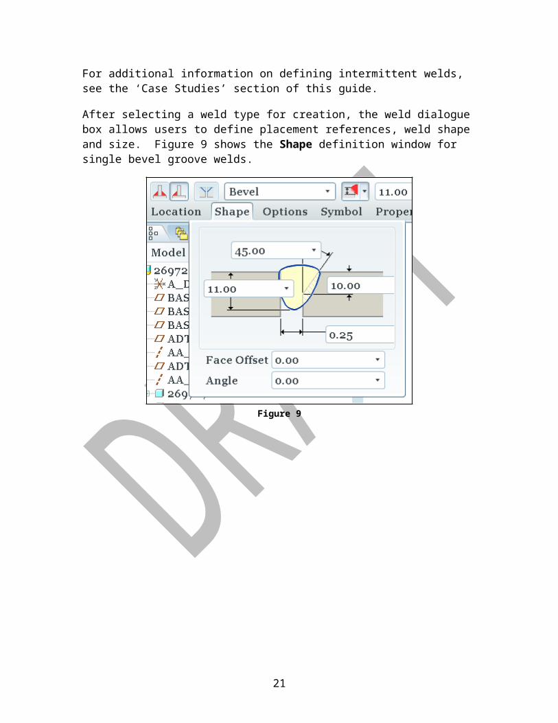
After selecting a weld type for creation, the weld dialogue box allows users to define placement references, weld shape and size. Figure 9 shows the Shape definition window for single bevel groove welds.
Figure 9
15
The weld feature interface provides the opportunity to define weld process information too.
Figure 10
The list of system-defined weld parameters is fairly lengthy. The values for most of these are automatically populated as the features are defined.
Figure 11
For a complete listing of all of the system defined welding parameters, please see Appendix B.
16
Weld Symbols & Drawings
Parametric Weld Symbols:
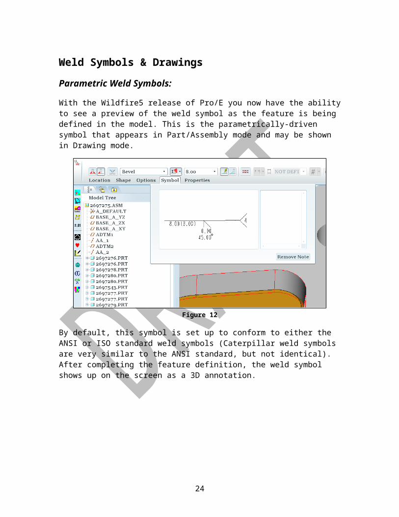
With the Wildfire5 release of Pro/E you now have the ability to see a preview of the weld symbol as the feature is being defined in the model. This is the parametrically-driven symbol that appears in Part/Assembly mode and may be shown in Drawing mode.
Figure 12
By default, this symbol is set up to conform to either the ANSI or ISO standard weld symbols (Caterpillar weld symbols are very similar to the ANSI standard, but not identical). After completing the feature definition, the weld symbol shows up on the screen as a 3D annotation.
17
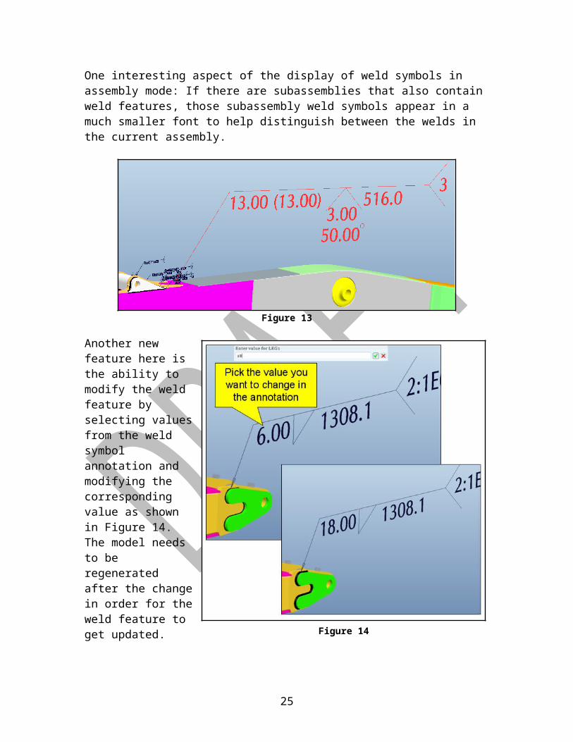
One interesting aspect of the display of weld symbols in assembly mode: If there are subassemblies that also contain weld features, those subassembly weld symbols appear in a much smaller font to help distinguish between the welds in the current assembly.
Figure 13
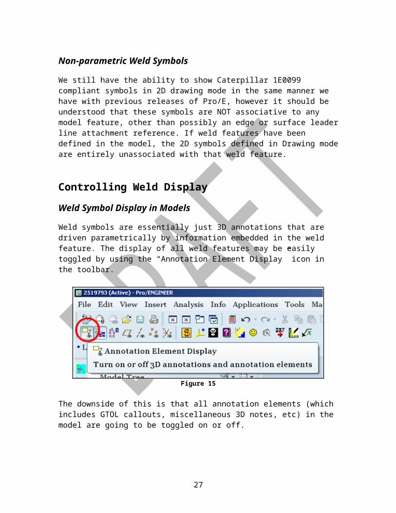
Another new feature here is the ability to modify the weld feature by selecting values from the weld symbol annotation and modifying the corresponding value as shown in Figure 14. The model needs to be regenerated after the change in order for the weld feature to get updated.
The symbol may be shown in Drawing mode as well (this capability has been available in all releases of Pro/E). In order for these parametrically-driven symbols to conform to the Caterpillar 1E0099 standards, additional work will be required to set up the custom symbols library.
18
Figure 14
Non-parametric Weld Symbols
We still have the ability to show Caterpillar 1E0099 compliant symbols in 2D drawing mode in the same manner we have with previous releases of Pro/E, however it should be understood that these symbols are NOT associative to any model feature, other than possibly an edge or surface leader line attachment reference. If weld features have been defined in the model, the 2D symbols defined in Drawing mode are entirely unassociated with that weld feature.
Controlling Weld Display
Weld Symbol Display in Models
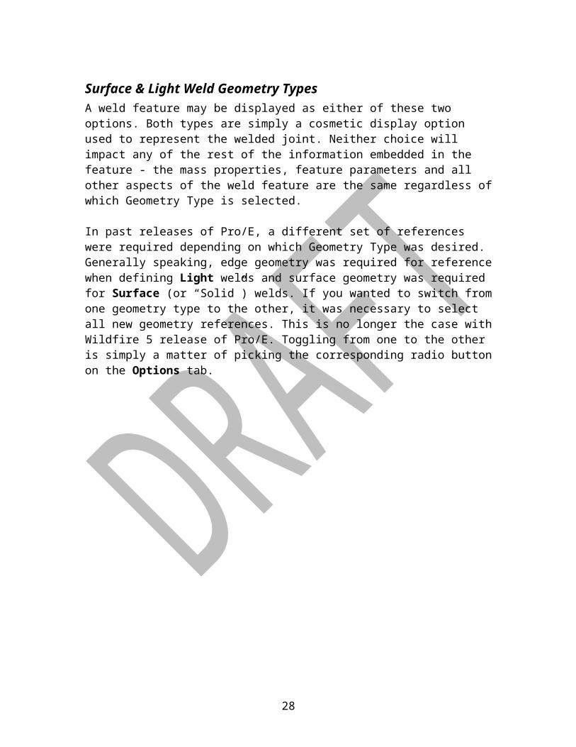
Weld symbols are essentially just 3D annotations that are driven parametrically by information embedded in the weld feature. The display of all weld features may be easily toggled by using the “Annotation Element Display” icon in the toolbar.
Figure 15
The downside of this is that all annotation elements (which includes GTOL callouts, miscellaneous 3D notes, etc) in the model are going to be toggled on or off.
19

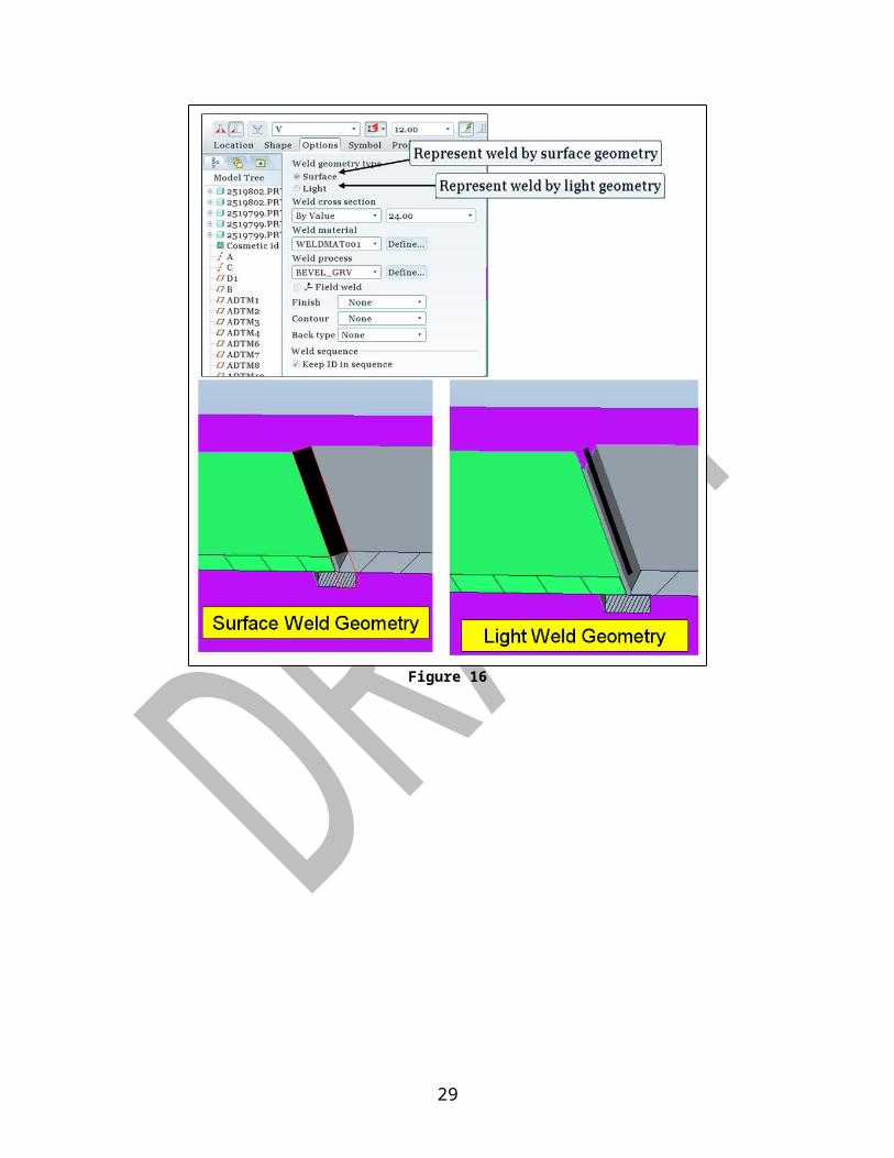
Surface & Light Weld Geometry TypesA weld feature may be displayed as either of these two options. Both types are simply a cosmetic display option used to represent the welded joint. Neither choice will impact any of the rest of the information embedded in the feature - the mass properties, feature parameters and all other aspects of the weld feature are the same regardless of which Geometry Type is selected.
In past releases of Pro/E, a different set of references were required depending on which Geometry Type was desired. Generally speaking, edge geometry was required for reference when defining Light welds and surface geometry was required for Surface (or “Solid”) welds. If you wanted to switch from one geometry type to the other, it was necessary to select all new geometry references. This is no longer the case with Wildfire 5 release of Pro/E. Toggling from one to the other is simply a matter of picking the corresponding radio button on the Options tab.
Figure 16
20
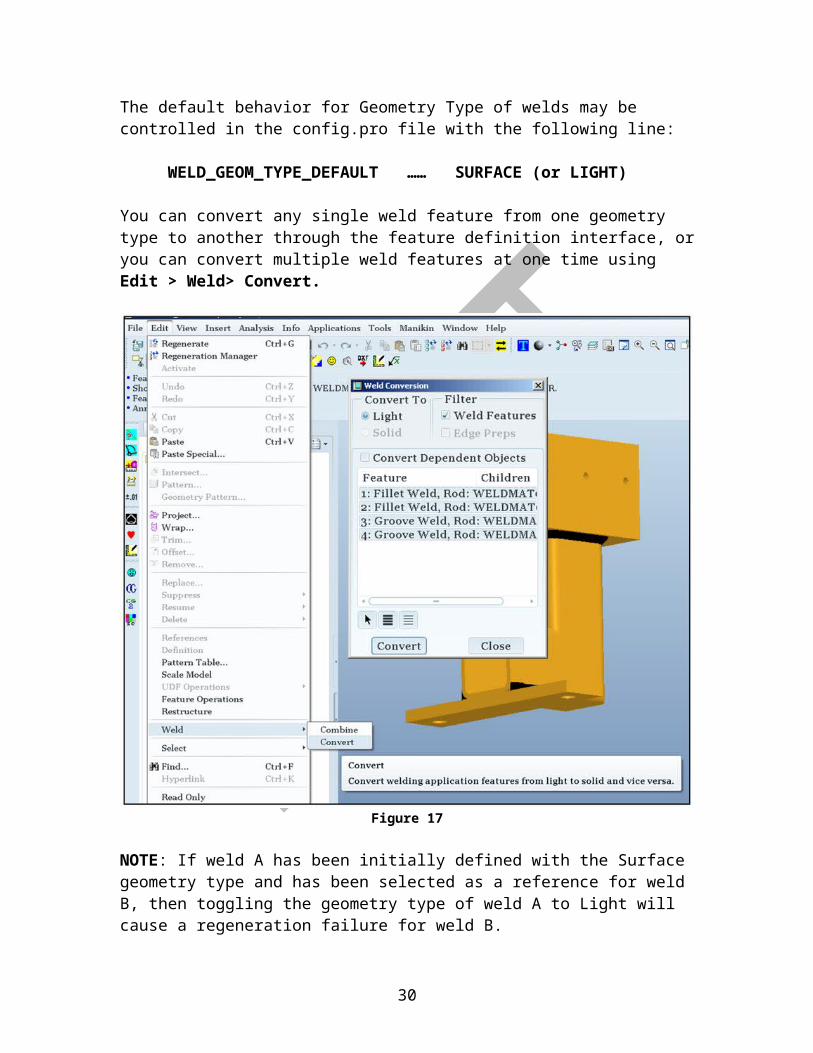
The default behavior for Geometry Type of welds may be controlled in the config.pro file with the following line:
WELD_GEOM_TYPE_DEFAULT …… SURFACE (or LIGHT)
You can convert any single weld feature from one geometry type to another through the feature definition interface, or you can convert multiple weld features at one time using Edit > Weld> Convert.
Figure 17
NOTE: If weld A has been initially defined with the Surface geometry type and has been selected as a reference for weld B, then toggling the geometry type of weld A to Light will cause a regeneration failure for weld B.
21

Standard Color For WeldsThe method for assigning a default color for the Surface-type weld features is by using the following config.pro option:
weld_color 0 0 0
This setting results in welds that are pure black as shown in Figure 22.
Figure 18
If you have a black background and would prefer to see a slight contrast, a charcoal gray color seems to work well too. That can be achieved by setting the option to this setting: weld_color 80 80 80
You can also set up standard appearance for Light Welds to change color & line thickness.
22

Suggested Layer Usage
Suggested Layer Usage For Weld Features in ModelsThe ability to display weld symbols parametrically driven by weld features in the part & assembly models was added with the Pro/E Wildfire 5 release. In this release, the behavior of this tool is such that the weld symbols appear on the display by default. If there are more than a couple of weld features in the model, you can imagine how quickly the screen gets cluttered with these symbols. In most cases it would be desirable to see the weld feature but not the weld symbol in part and/or assembly mode2. As noted earlier, you can turn off the symbol annotations in the mode by toggling the icon for Annotation Element Display, but this turns off all annotations – not just the weld symbols, so this isn’t exactly the desired result either. Until the default behavior of weld symbol display changes, the following workaround technique using layers in Pro/E is suggested.
Layers have long been used in our models as an organizational tool. By associating items with a layer, we can collectively manipulate features including such operation as deleting, reordering, suppressing, or hiding and unhiding them as necessary.
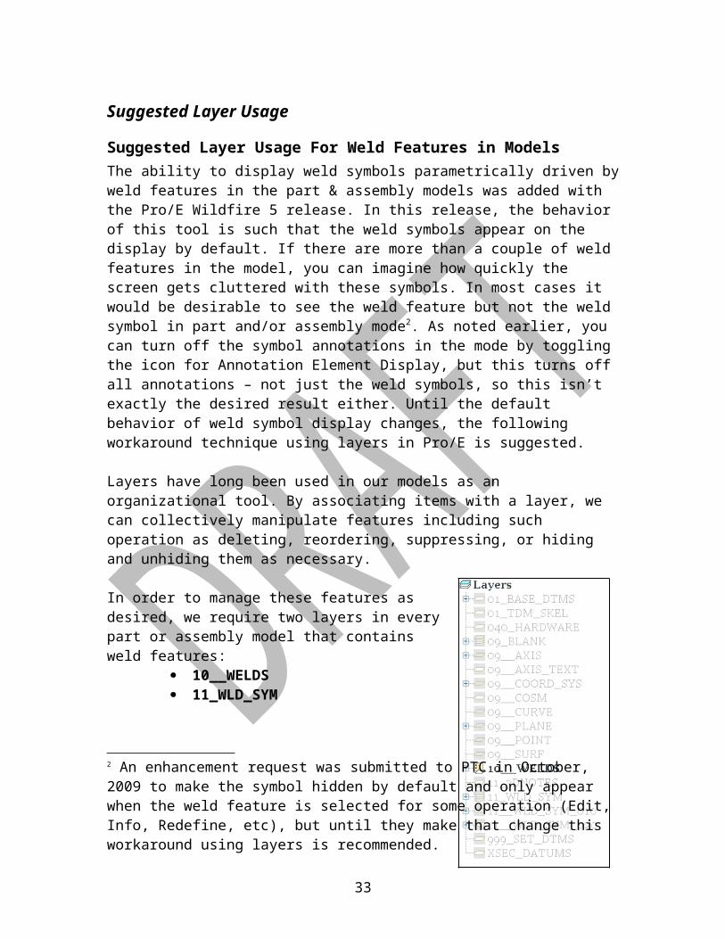
In order to manage these features as desired, we require two layers in every part or assembly model that contains weld features:
10__WELDS 11_WLD_SYM
The first layer will contain all the surface quilts associated with the weld features. These quilts can be automatically assigned to the 10__WELDS layer by using Layer Rules. The surface quilts for all weld features created when this layer resides in the model are automatically added to this default layer. If this layer is hidden, the surface quilt for all weld features in the model would be affected, however there should be no change on the weld symbol annotation. This layer configuration has no bearing on weld symbols created in the drawing as non-parametric weld symbols.
2 An enhancement request was submitted to PTC in October, 2009 to make the symbol hidden by default and only appear when the weld feature is selected for some operation (Edit, Info, Redefine, etc), but until they make that change this workaround using layers is recommended.
23
Figure 19
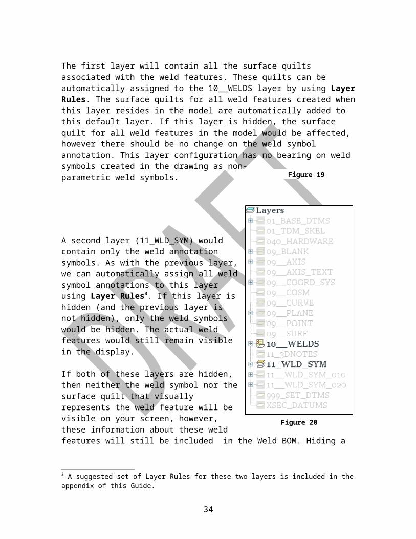
A second layer (11_WLD_SYM) would contain only the weld annotation symbols. As with the previous layer, we can automatically assign all weld symbol annotations to this layer using Layer Rules3. If this layer is hidden (and the previous layer is not hidden), only the weld symbols would be hidden. The actual weld features would still remain visible in the display.
If both of these layers are hidden, then neither the weld symbol nor the surface quilt that visually represents the weld feature will be visible on your screen, however, these information about these weld features will still be included in the Weld BOM. Hiding a feature (or a component of a feature) only changes the display.
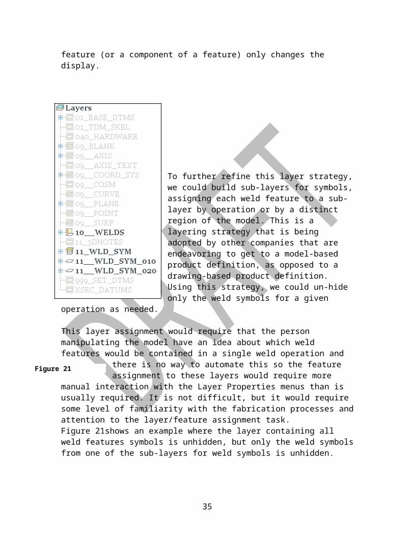
To further refine this layer strategy, we could build sub-layers for symbols, assigning each weld feature to a sub-layer by operation or by a distinct region of the model. This is a layering strategy that is being adopted by other companies that are endeavoring to get to a model-based product definition, as opposed to a drawing-based product definition. Using this strategy, we could un-hide only the weld symbols for a given operation as needed.
This layer assignment would require that the person manipulating the model have an idea about which weld features would be contained in a single weld operation and there is no way to automate this
so the feature assignment to these layers would require more manual interaction with the Layer Properties menus than is usually required. It is not difficult, but it would require some level of familiarity with the
3 A suggested set of Layer Rules for these two layers is included in the appendix of this Guide.
24
Figure 20
Figure 21
fabrication processes and attention to the layer/feature assignment task.Figure 21shows an example where the layer containing all weld features symbols is unhidden, but only the weld symbols from one of the sub-layers for weld symbols is unhidden.
Figure 22
The downside of this is the weld symbol in part or assembly mode will never be displayed unless you unhide the corresponding layer. Of course, weld features and weld symbols may be hidden individually too, but standardizing on layer usage before this tool gets into widespread use is probably a good idea.
25

Suggested Layer Usage For Weld Features in DrawingsThe typical behavior we would like to see with welds symbol in Drawing mode is hidden weld feature geometry and un-hidden weld symbol annotation.
If we have applied the layer structure as suggested in the previous section, then this scenario is easily accomplished by hiding the layer for the weld feature quilts (10__WELDS) and making sure the other layer (11_WLD_SYM) is not hidden.
The only downside of this is that the weld symbol leader lines were probably originally attached to the weld surface quilts. Since those quilts have been hidden in drawing mode, the leader lines for the weld symbols may need to be re-attached so the arrowhead isn’t hanging in space.
Figure 23
26
Mass Property Calculations of Weld FeaturesPro/E calculates the mass of a weld joint by using the product of three factors:
Joint length Density of the weld filler material Cross-sectional area of the weld
If any of these 3 factors are missing or incorrect, the returned value for weld volume and mass will obviously be incorrect as well. The first two factors are fairly automatic and require very little attention from the designer.
Weld Length: This value is automatically determined by the geometry referenced in the weld definition. If the correct geometry has been identified, no additional information is required. Any changes to the model which alter the length of the weld geometry will automatically update this factor of the weld mass.
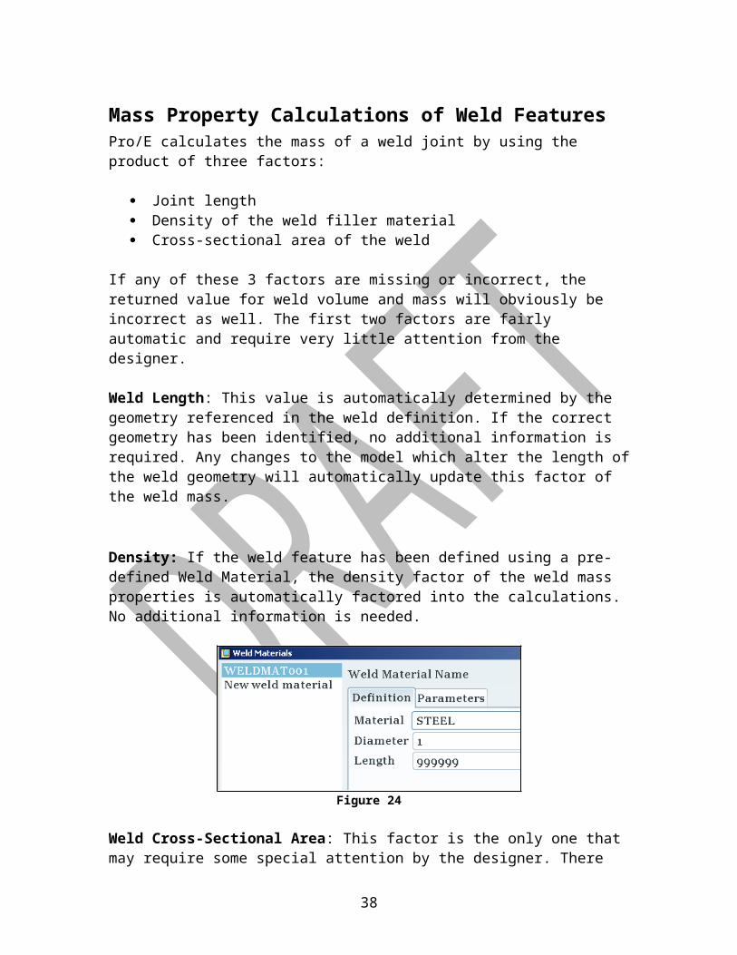
Density: If the weld feature has been defined using a pre-defined Weld Material, the density factor of the weld mass properties is automatically factored into the calculations. No additional information is needed.
Figure 24
Weld Cross-Sectional Area: This factor is the only one that may require some special attention by the designer. There are a couple of ways to define the area of the weld; however all of these methods will only provide the area of a single cross-sectional area of the weld joint. If there is some variation in the joint which causes the area to fluctuate through the length of the weld joint, this variation is unaccounted for.
27
There are two different ways that may be used to define a weld cross-sectional area:
Method #1: Using the Weld Cross Section By Value option
Figure 25
This method quickly allows you to get a good approximation of the weld mass calculated and included into the mass properties of the model. That mass calculation is only as good as the quality of the input data though. The hard-coded value for the weld cross-sectional area must be as accurate as possible and the density needs to be declared with a good weld material.
You can refer to the Case Studies section of this guide for a method to ensure the weld cross-sectional area is as accurate as possible and automatically updates with design changes.
28
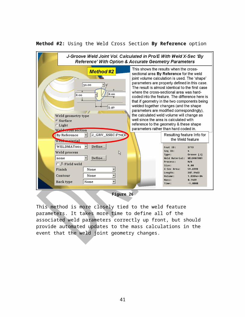
Method #2: Using the Weld Cross Section By Reference option
Figure 26
This method is more closely tied to the weld feature parameters. It takes more time to define all of the associated weld parameters correctly up front, but should provide automated updates to the mass calculations in the event that the weld joint geometry changes.
At this time, the suggested technique for getting the mass properties for welds is to use Method #1.
29
NOTE: With the current build of Pro/E Wildfire 5, the weld joint parameters for J-groove and U-groove welds is not accurate in the sense that there is no way to account for the radii at the bottom of these two types of weld joints. The resulting difference in the mass property calculations is not significant, however this problem has been reported to PTC and should be fixed in a later release.
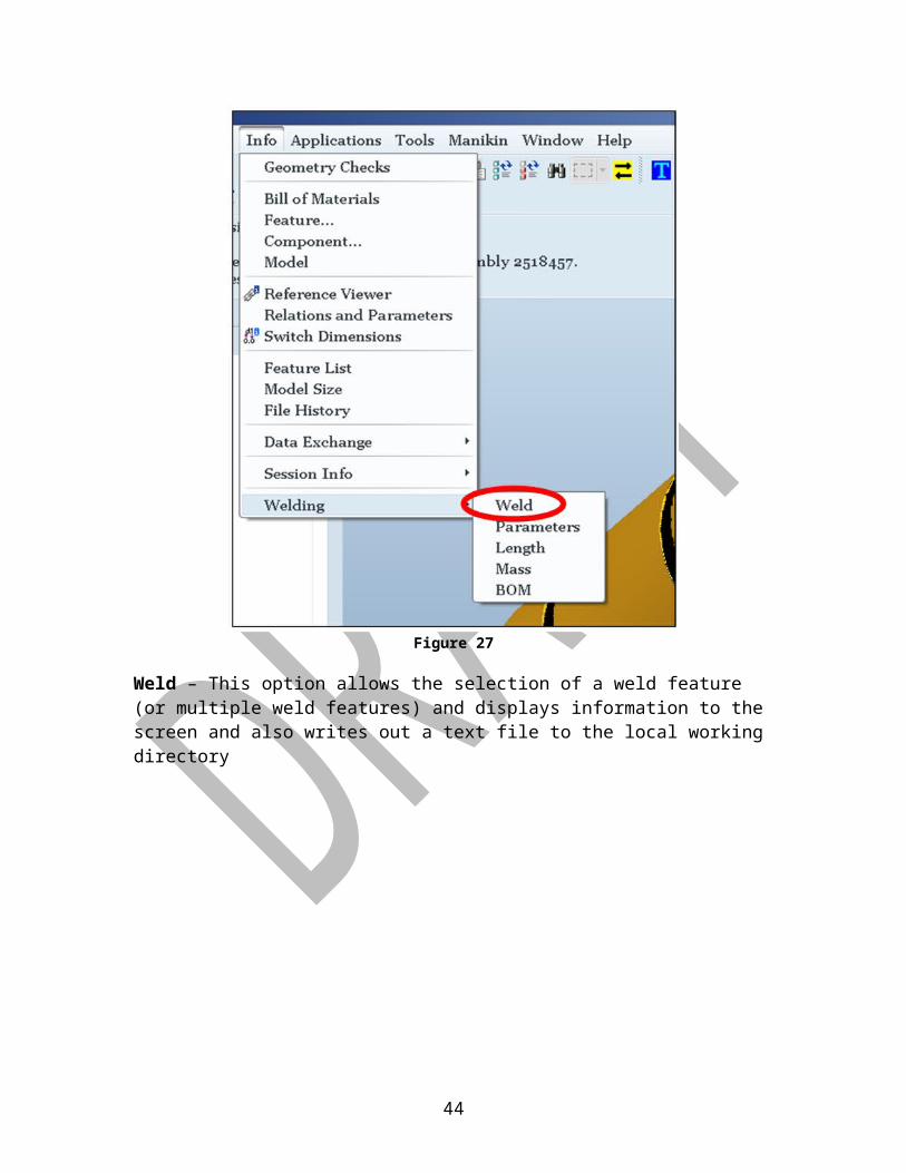
Weld InfoWelding information provides general data about welding design features, including the assembly name, weld type, welding materials, mass properties, and any welding processes assigned. The following information about weld features in the design may be obtained:
Overall attributes of welds Length of weld joints Length of weld wire required to make the welds Mass of welds Parameters assigned to each weld feature Weld Bills of Materials for the assembly
This information is all accessed from the ‘INFO’ pull-down menu:
Figure 27
Weld – This option allows the selection of a weld feature (or multiple weld features) and displays information to the screen and also writes out a text file to the local working directory
30

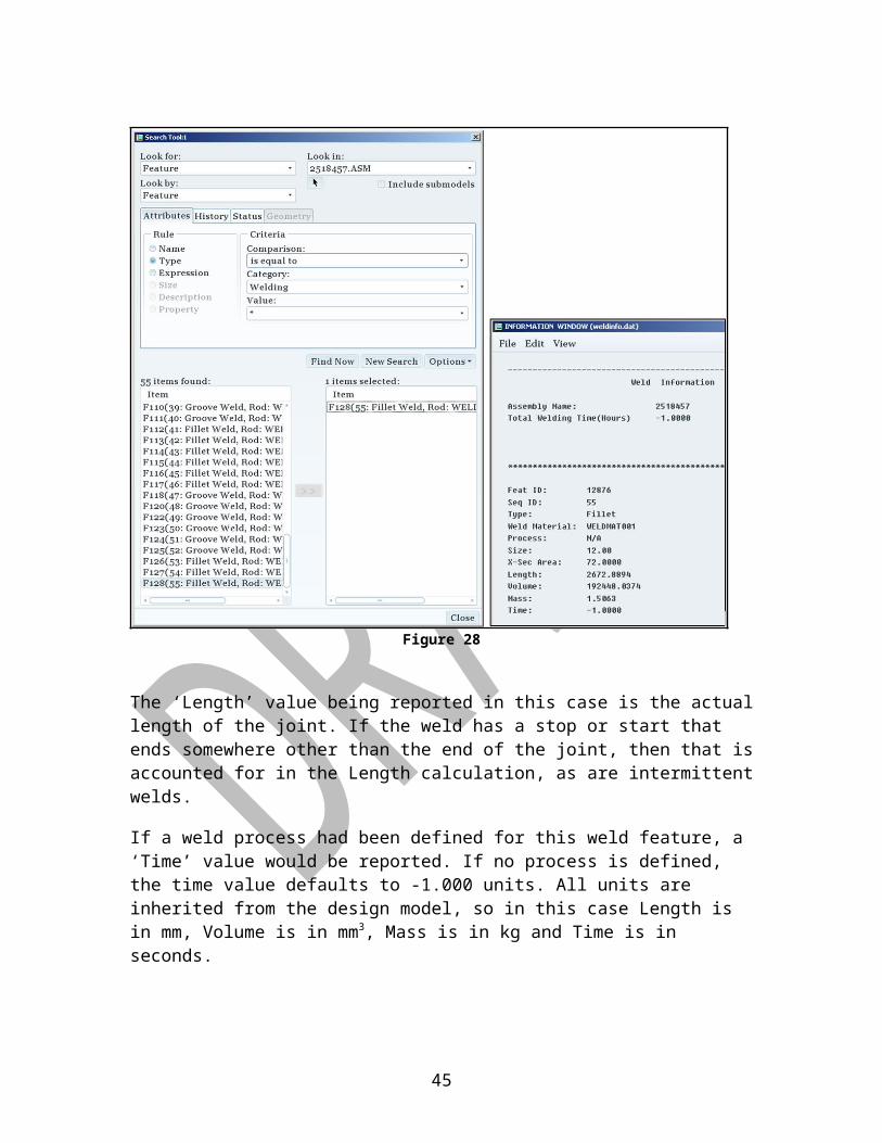
Figure 28
The ‘Length’ value being reported in this case is the actual length of the joint. If the weld has a stop or start that ends somewhere other than the end of the joint, then that is accounted for in the Length calculation, as are intermittent welds.
If a weld process had been defined for this weld feature, a ‘Time’ value would be reported. If no process is defined, the time value defaults to -1.000 units. All units are inherited from the design model, so in this case Length is in mm, Volume is in mm3, Mass is in kg and Time is in seconds.
31

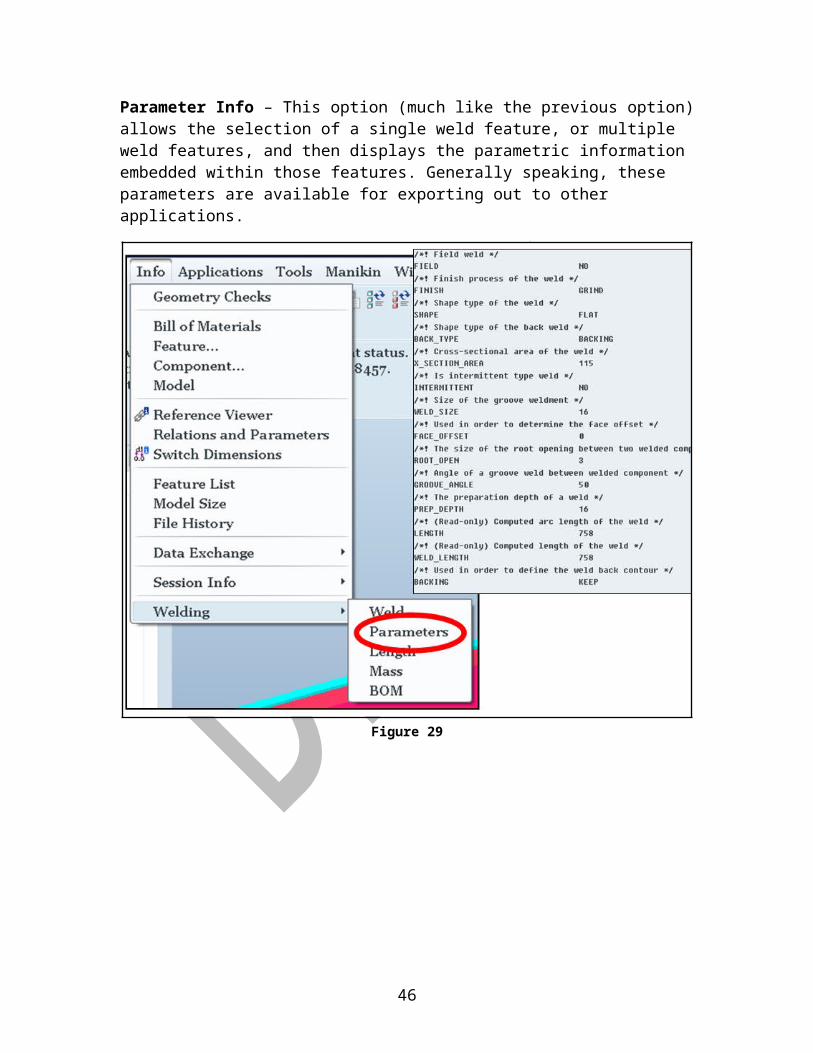
Parameter Info – This option (much like the previous option) allows the selection of a single weld feature, or multiple weld features, and then displays the parametric information embedded within those features. Generally speaking, these parameters are available for exporting out to other applications.
Figure 29
32
Weld Length Info – The third option from the Welding Info menu provides for the ability to display either just the length of a weld feature, or the length or weld filler material required to complete all the welds in the current model that use the selected filler material.
Figure 30
33
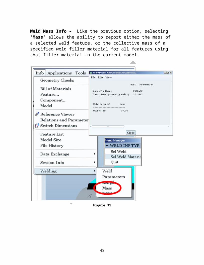
Weld Mass Info – Like the previous option, selecting ‘Mass’ allows the ability to report either the mass of a selected weld feature, or the collective mass of a specified weld filler material for all features using that filler material in the current model.
Figure 31
34
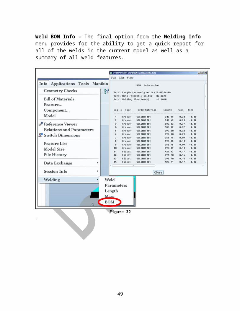
Weld BOM Info – The final option from the Welding Info menu provides for the ability to get a quick report for all of the welds in the current model as well as a summary of all weld features.
Figure 32.
35

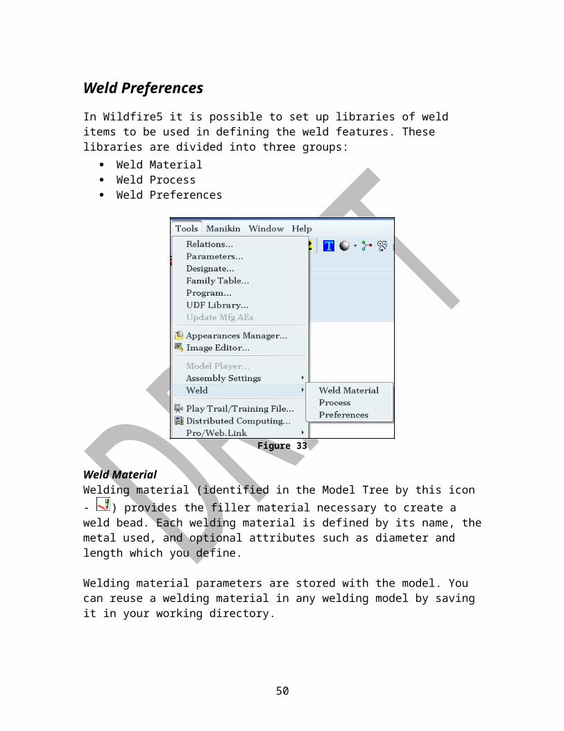
Weld Preferences
In Wildfire5 it is possible to set up libraries of weld items to be used in defining the weld features. These libraries are divided into three groups:
Weld Material Weld Process Weld Preferences
Figure 33
Weld Material
Welding material (identified in the Model Tree by this icon - ) provides the filler material necessary to create a weld bead. Each welding material is defined by its name, the metal used, and optional attributes such as diameter and length which you define.
Welding material parameters are stored with the model. You can reuse a welding material in any welding model by saving it in your working directory.
Define and work with welding materials almost exclusively in the Weld Materials dialog box. You can assign a welding material to a weld, and one welding material can be assigned to multiple welds. Use the shortcut menu to change a welding material assignment from within a weld feature, or choose Edit Definition to edit the weld by adding or changing a welding material.
When you delete a welding material that is assigned to a weld feature, you must also delete the weld that uses that material. To avoid having to delete the weld
36

feature, un-assign the welding material from the weld feature first, then delete the welding material.
Weld Process
A welding process is identified in the Model Tree by this icon - . You can streamline the creation of welding designs, ensure design consistency, and save time by defining processes.
Welding processes are defined almost exclusively in the Weld Processes dialog box. Typically, welding processes are defined before you create any welding features. However, you can assign and un-assign welding processes at any time in your design.
When you define a welding process you can:
Apply company or industry specifications
Assign a machine type
Indicate a treatment
Specify a feed rate4
Establish acceptable weld length and root opening size
You can further customize your welding process by assigning optional and user-defined parameters.
Within a welding model, each welding process is defined by its name and parameters. Processes are stored with the model. You can reuse a saved welding process in any welding model.
4 In the Wildfire 5 version of Pro/E, there is only one system defined parameter for ‘Feedrate’. This parameter is understood to be the travel rate of the welding torch down the length of the joint. A second user-defined parameter (WFS, type = Integer) needs to be defined for the wire-feed-speed rate. Both values must be defined in units recognized by the current model, which will typically be mm/sec.
37
Examples of welding process parameters:
Figure 34
A complete list of all of the system-defined weld parameters is included in Appendix B.
38

Weld Preferences
Welds created in sequence often share common characteristics. Defining preferences lets you define options that can be applied to many welds, with no need to define them for each weld. The preferences you define remain active for the current session.
Welding preferences are defined almost exclusively in the Weld Preferences dialog box. The options available differ based on the weld type and standard. Default values depend on the units you have set in the pro_unit_length configuration option.
When you define a welding preference you can:
Set measurements that determine weld shape
Set an intermittent weld scheme
Select predefined weld materials and processes
Indicate a field weld
Define weld finish and backing
Select a predefined appearance
Optimize how weld geometry and edge preparation are depicted
Indicate family table creation
Suggested settings for Weld Preferences may be found in Appendix C.
39

Weld Modeling Strategies
When should the weld feature be defined?
At this point, that’s a tricky question. Since there is so little experience in the usage of this tool, better practices may develop with time, but at this point, it appears to be advisable to build the assembly model using normal design practices. Once the BOM is relatively mature, it would be wise to review the design in a CPPD meeting with someone that can shed some light on a weld sequence. This is not required, but could help to reduce changes later. The reason for collaboration at this point is simply a matter of determining the structure and hierarchy of piece parts, subassemblies and top level assemblies.
What is Edge Prep and should it be used?
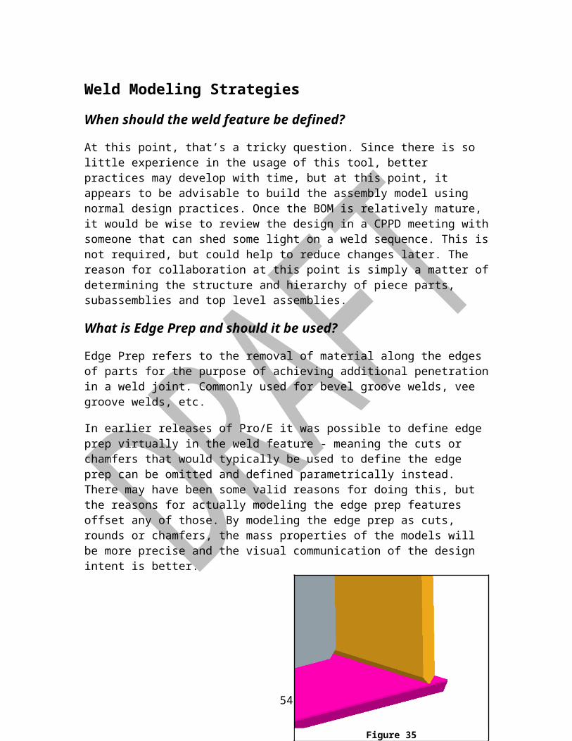
Edge Prep refers to the removal of material along the edges of parts for the purpose of achieving additional penetration in a weld joint. Commonly used for bevel groove welds, vee groove welds, etc.
In earlier releases of Pro/E it was possible to define edge prep virtually in the weld feature - meaning the cuts or chamfers that would typically be used to define the edge prep can be omitted and defined parametrically instead. There may have been some valid reasons for doing this, but the reasons for actually modeling the edge prep features offset any of those. By modeling the edge prep as cuts, rounds or chamfers, the mass properties of the models will be more precise and the visual communication of the design intent is better.
Figure 33 shows the edge preparation is modeled as a chamfer feature in the part model. This is typically the way we model edge preparation.
40
Figure 35
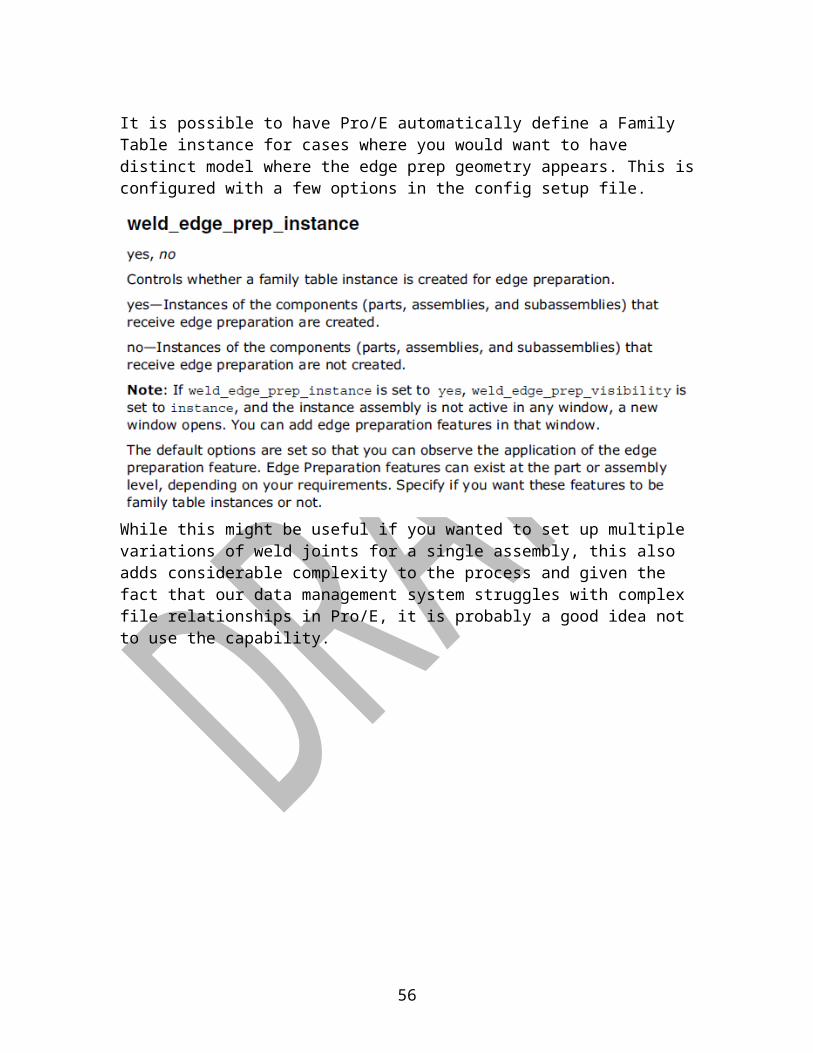
It is possible to have Pro/E automatically define a Family Table instance for cases where you would want to have distinct model where the edge prep geometry appears. This is configured with a few options in the config setup file.
While this might be useful if you wanted to set up multiple variations of weld joints for a single assembly, this also adds considerable complexity to the process and given the fact that our data management system struggles with complex file relationships in Pro/E, it is probably a good idea not to use the capability.
41
What are Weld Notches and should I use them?A weld notch is essentially nothing more than a clearance opening that enables you to place a component in an assembly without interfering with a previously existing weld joint (the notch is circled in Figure 34).
We have the option of defining these notches as special features within the Pro/E Welding application, if desired. The idea is that if you use Standard and User-Defined notch shapes this will enable you to automate and standardize the weld notches in your design, ensuring design consistency and saving you time. You can create single weld notches or you can combine weld notches with edge preparation and weld features. You can only combine weld notches and edge preparations if you simultaneously create a weld feature.
Typically what we see at Caterpillar is that these types of cuts are simply made as normal cut features in the part mode, so usage of weld notch features in the Welding application is seldom (if ever) advisable.
42
Figure 36
At which level should the weld feature be included?
The weld features should be created as features in the level where they will be performed. As stated earlier, in some cases this might be at the piece part level, but usually welds will be located in the assembly.
Can welds be patterned? Should they be patterned?
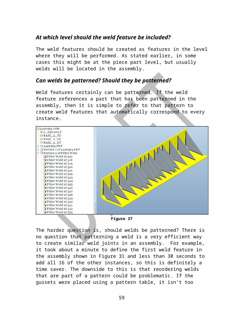
Weld features certainly can be patterned. If the weld feature references a part that has been patterned in the assembly, then it is simple to refer to that pattern to create weld features that automatically correspond to every instance.
Figure 37
The harder question is, should welds be patterned? There is no question that patterning a weld is a very efficient way to create similar weld joints in an assembly. For example, it took about a minute to define the first weld feature in the assembly shown in Figure 31 and less than 30 seconds to add all 16 of the other instances, so this is definitely a time saver. The downside to this is that reordering welds that are part of a pattern could be problematic. If the gussets were placed using a pattern table, it isn’t too difficult to modify that table so that the sequence of parts added to the assembly matches the actual assembly/welding sequence, but if the pattern was created as a simple dimensional pattern, then it could prove to be much more troublesome to get the weld sequences modified.
It becomes a question of speed vs. flexibility. Under the current set of conditions where we really do not have any downstream application use of the weld features in Pro/E, it probably makes more sense to define similar components using patterns so that the reference pattern option can be used when defining
43
associated weld joints. If the function of weld process engineering using the Pro/E weld features gets implemented at Caterpillar, then the better choice will probably be to define the welds without referencing the patterns.
There are other ways to quickly duplicate existing weld features on similar joints that may be more desirable if dealing with the patterns and weld sequence numbers becomes too problematic.
Are there other options for duplicating weld features?If you choose not to utilize the reference pattern option to quickly define weld features, there are some other options that are available to help create features efficiently and consistently.
The first option is to use the Weld Preferences as described earlier in this guide. This allows you to set up default values for various types of welds so that there will be a set of pre-defined values entered for all required fields. Once the feature has been placed you can make any desired modifications.
The second option is to simply use Edit> Copy and Edit> Paste or Edit> Copy and Edit> Paste Special. In order to use this option, you would need to have a pre-existing model in your session that has weld features similar to the one you want to add to your current model. One possible way to use this option efficiently would be to create a weld template model that contains all of your frequently used weld features. Bring that model up into session so you can copy weld features from that template model into the active design.
Another commonly used option for reusing existing features is to set up and apply User-Defined Features (UDFs) for frequently used feature types. This option does not work for weld features in the current version of Pro/E.
44
NOTE: If you do use this COPY & PASTE function for welds, be very careful to make sure that you are in the WELDING application in the design model when you perform the PASTE operation. Pro/E will abort the session if you are in Standard mode and try to paste a weld feature into the active model. This software bug was reported to PTC in November 2009 and should be resolved in a future build. The reference number for the call was C7389294.
When should similar welds be combined?
The ability to combine multiple sets of welds of a similar type is another new capability that presents both advantages and disadvantages. By combining multiple joints into a single weld feature, it makes creation and modification of the welds quick and efficient.
Figure 38
The downside of this is when the process for manufacturing these welds needs to be handled individually rather than as a group. In that case, the welds would need to be broken out from the group into individual weld features.
45
You can also combine multiple weld joints that are similar into a single weld features. Like in the previous case, this is a way to get many weld features defined quickly; however it places limitations on the weld processing capabilities. That may or may not be an issue.
Figure 39
Note how the length of weld for the single weld feature now reports the total length of both similar welds that were combined into one feature.
46

How should tack welds be handled?At this point, there is no option to define tack welds specifically within the Pro/WELD module. Annotation features may be used to indicate where take welds are to be placed if necessary.
Figure 40
47
How should surface welds be handled?There is also no option for defining a surface weld as defined by section 8.9 of Caterpillar Specification 1E0099. ”Surfacing involves overlaying a specified area with a weld deposit. The two most common applications for arc weld surfacing are hard-facing (for wear resistance) and buttering (to provide a ductile, crack-resistant transition layer).”One method that could be used to communicate a surface weld in the Pro/E model would be to define a surface feature in the model in the area where the surface weld is to be placed. Define and attach a 3D annotation using the weld symbol library
Figure 41
This will not have the weld feature parameters embedded in it like a regular weld feature and will not roll up into the weld BOM or be available for Info interrogation like all of the legitimate weld features, but might be useful for visually communicating a surface feature in the model until such time as the Surface weld becomes available as a regular weld feature type.
48
Case Studies
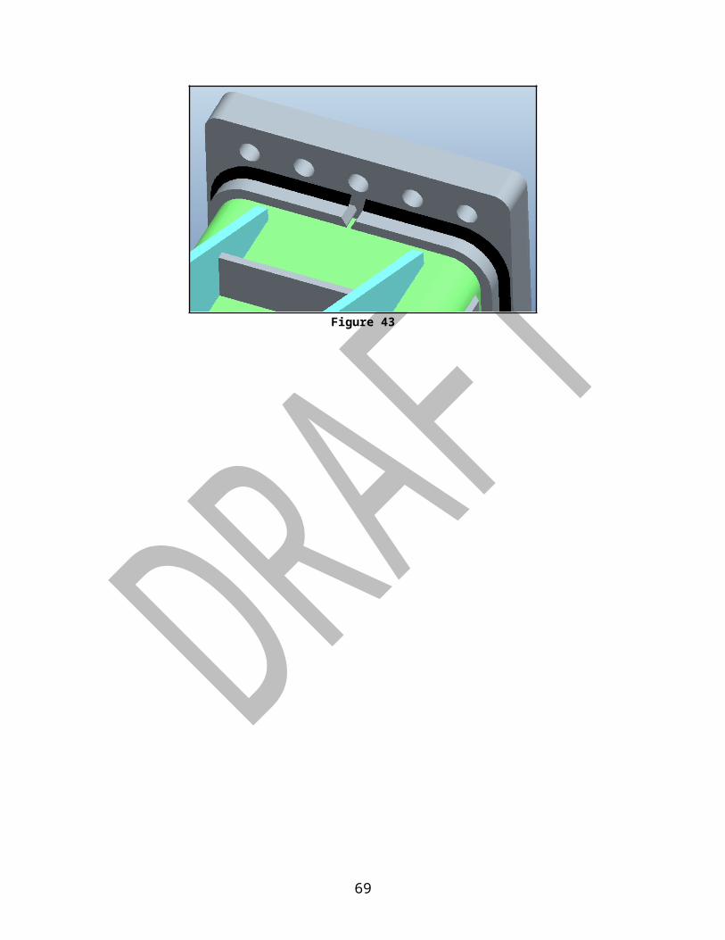
Continuous Weld Joints Spanning Gaps Between PlatesOne of the problems frequently faced when attempting to model welds in Pro/E is this issue of creating a weld that extends continuously across gaps between components. A simple example of this is shown below where we would like to extend a fillet welds all round this area.
Figure 42
If you were to pick the surface indicated on the flat plate as the Side 1 reference and the other two surfaces for the Side 2 references, the result would be like that shown below, an interrupted weld joint with two segments.
Figure 43
49
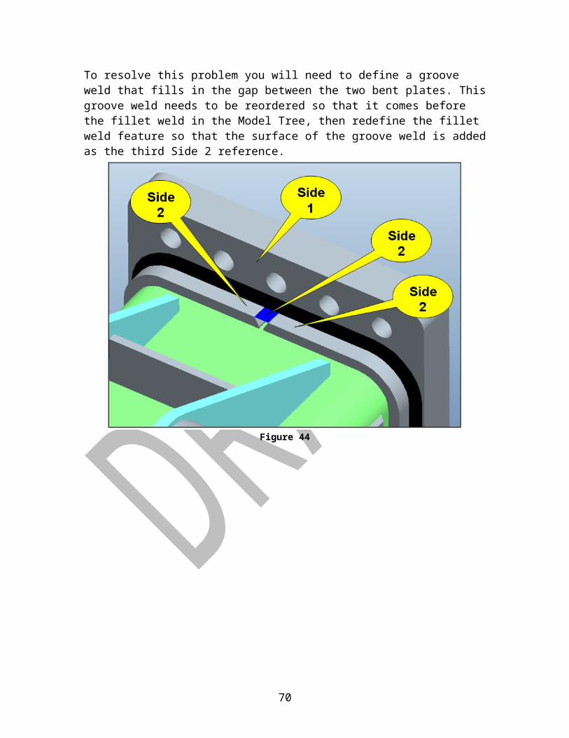
To resolve this problem you will need to define a groove weld that fills in the gap between the two bent plates. This groove weld needs to be reordered so that it comes before the fillet weld in the Model Tree, then redefine the fillet weld feature so that the surface of the groove weld is added as the third Side 2 reference.
Figure 44
50
Using Weld Features in Pro/MECHANICA
When running Pro/MECHANICA structural analyses on a model, assembly components are joined together with “simulation welds”. In the past the analyst would have to select geometry that was being joined by the simulation connection. This may still be accomplished the old way, but with Wildfire 5, weld features from the model may be used to automate the simulation connections. In order to use this capability, it is necessary to define the default interface type to be Free rather than Bonded.
Figure 45
If a weld feature has been defined in the model, it is possible to use that information to make connections between assembly parts joined by welds.
Figure 46
The results of using this type of weld geometry in Pro/MECHANICA are currently undergoing closer investigation, but it appears that this type of weld definition does not provide an accurate picture of how a welded assembly behaves since it has no stiffness or surface area, and therefore is not recommended at this time.
51
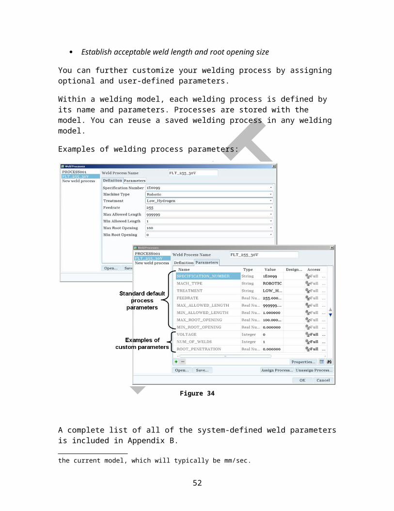
Figure 47
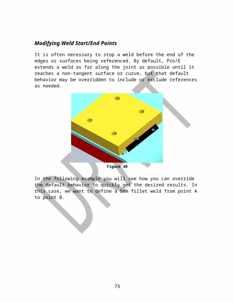
Modifying Weld Start/End Points
It is often necessary to stop a weld before the end of the edges or surfaces being referenced. By default, Pro/E extends a weld as far along the joint as possible until it reaches a non-tangent surface or curve, but that default behavior may be overridden to include or exclude references as needed.
Figure 48
52
In the following example you will see how you can override the default behavior to quickly get the desired results. In this case, we want to define a 5mm fillet weld from point A to point B.
Figure 49
By default, the box is checked to ‘Allow tangent propagation’ which means that if you select a surface for a weld reference, it will extend that weld as long as it finds tangent faces. In this case though, we want to override that and select each face we want to include as a weld reference surface, so remove the check from that box and select the desired references.
Figure 50
53
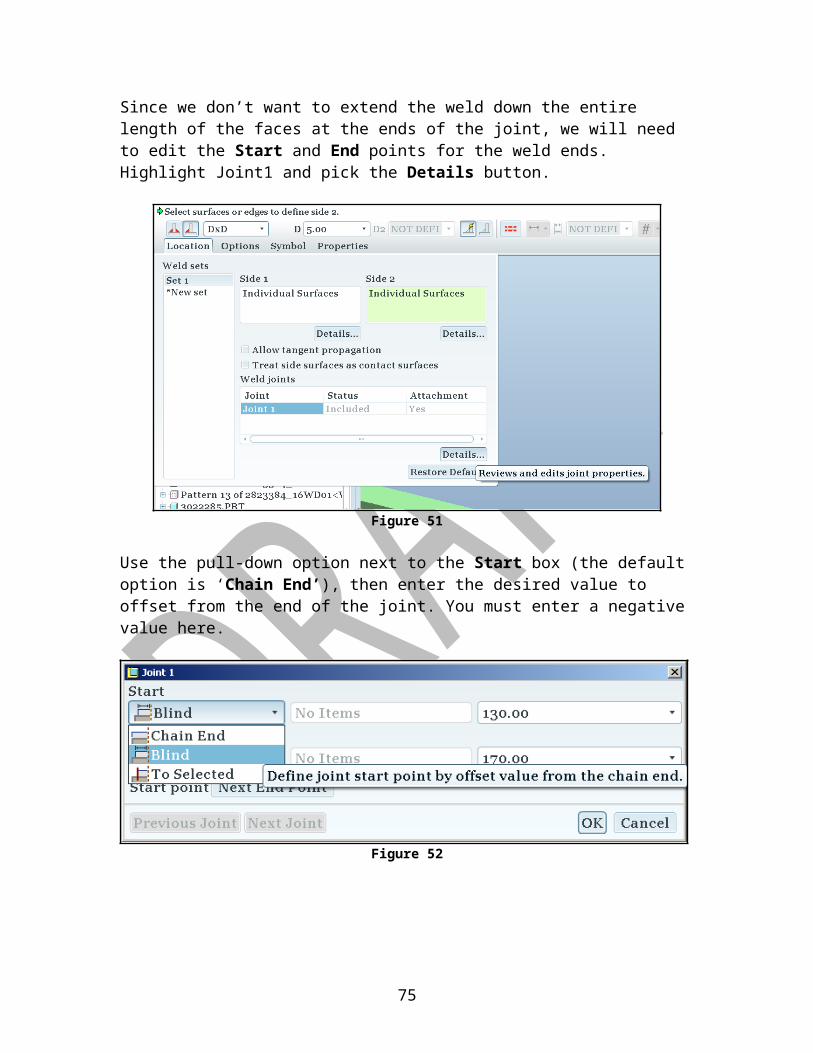
Since we don’t want to extend the weld down the entire length of the faces at the ends of the joint, we will need to edit the Start and End points for the weld ends. Highlight Joint1 and pick the Details button.
Figure 51
Use the pull-down option next to the Start box (the default option is ‘Chain End’), then enter the desired value to offset from the end of the joint. You must enter a negative value here.
Figure 52
54

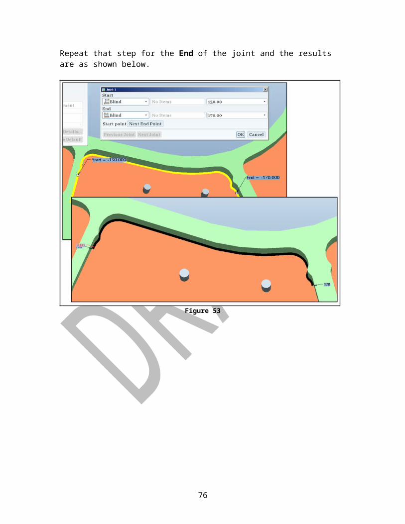
Repeat that step for the End of the joint and the results are as shown below.
Figure 53
55
Creating Intermittent WeldsIn this first example, an intermittent 5mm bevel groove weld will be constructed.The first step is to define the basic bevel groove weld. As discussed earlier, you can select the little arrow next to the groove weld icon on the toolbar to expand that set of tools. In this case, we will choose the icon for bevel groove welds.
Figure 54
Set up the basic weld by selecting the desired reference geometry, defining the feature shape parameters, and related options. If you were to complete the operation at this point, it would result in a bevel groove weld that extended the length of the reference edge. But since you want to define this as an intermittent weld joint, a little more information needs to be included.
56
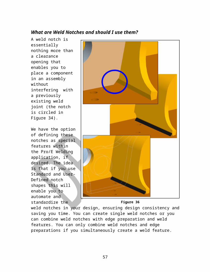
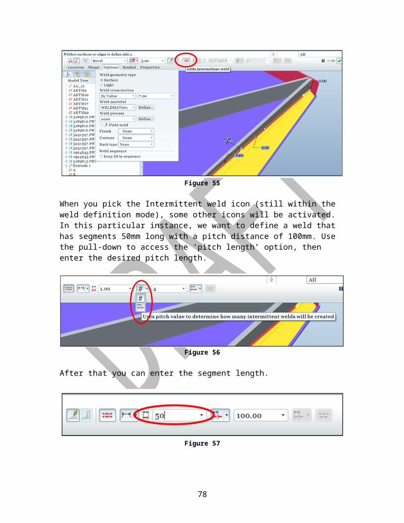
Figure 55
When you pick the Intermittent weld icon (still within the weld definition mode), some other icons will be activated. In this particular instance, we want to define a weld that has segments 50mm long with a pitch distance of 100mm. Use the pull-down to access the ‘pitch length’ option, then enter the desired pitch length.
Figure 56
After that you can enter the segment length.
Figure 57
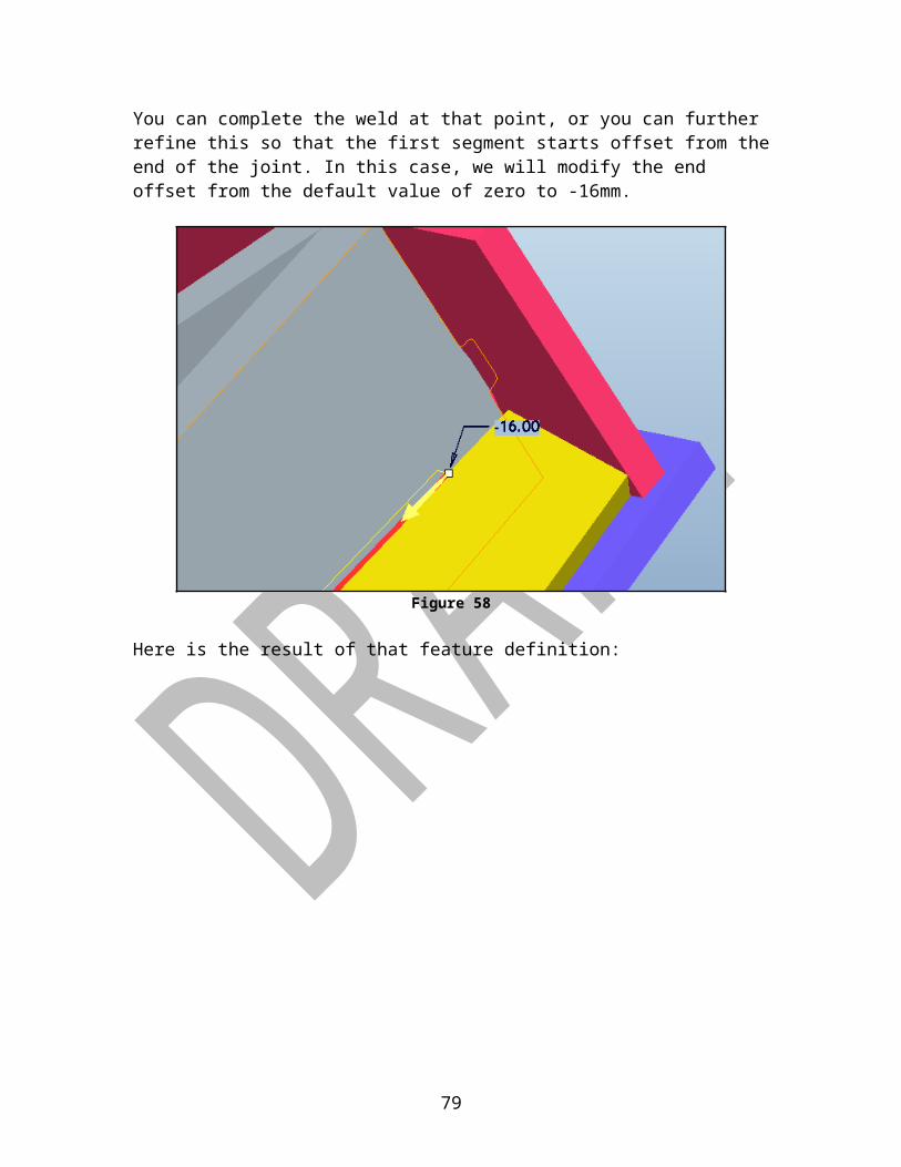
You can complete the weld at that point, or you can further refine this so that the first segment starts offset from the end of the joint. In this case, we will modify the end offset from the default value of zero to -16mm.
57

Figure 58
Here is the result of that feature definition:
Figure 59
58
In this second example, we will make an intermittent 3mm staggered fillet weld.
Figure 60
Once the basic intermittent welds have been defined, you need to select one side or the other to offset the start point. Highlight the Joint and use the Details button to modify the starting point of that joint.
Figure 61
59
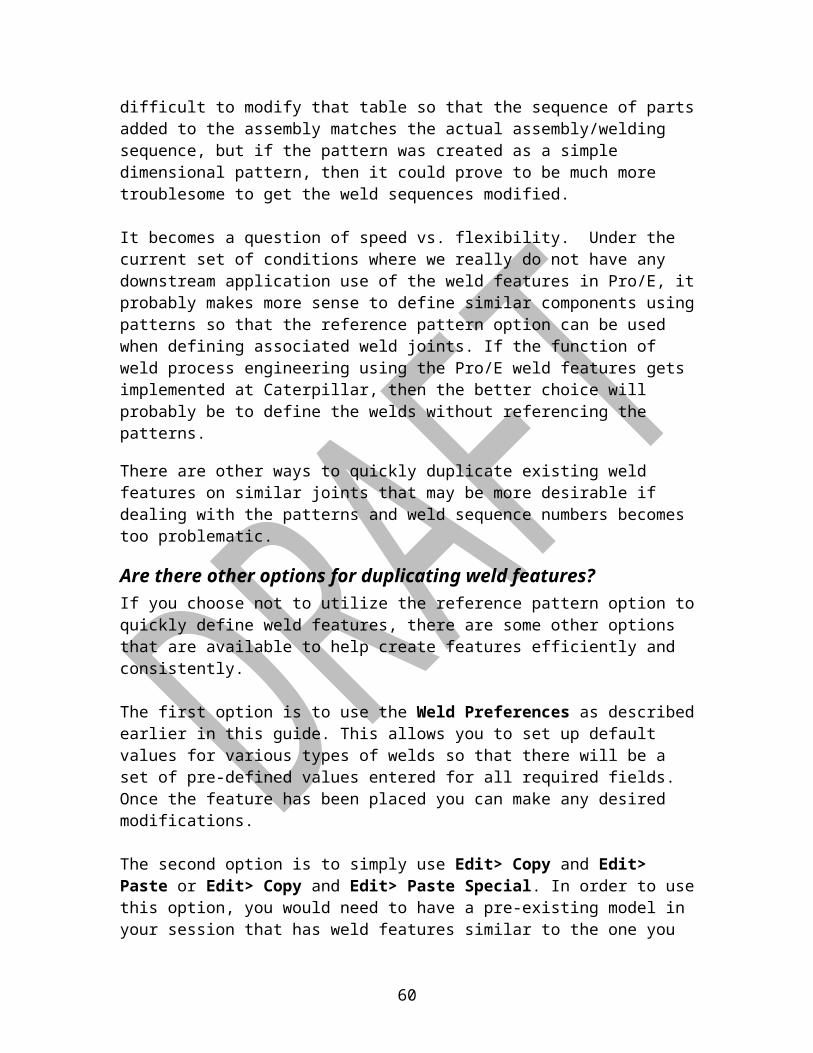
Figure 62Note that the resulting length, volume and mass for that weld are for both sides of the weld feature.
Figure 63
Figure 64
60

Modeling Complex Weld Joints
In this example we have a U-groove joint that joins the bent plate with the casting. This will be an 8mm weld that extends from point A to point B.The references we have available to use when defining a J-groove are:Side 1: Chain (edges or curves)Side 2: Chain OR Surfaces
If the tangent chain on the edge of the bent plate is selected as the Side 1 reference and the series of surfaces on the casting that the weld would be attached to are used for the Side 2 reference the resulting weld appears to not fill the entire joint.
Figure 66
61
Figure 65

Of course the weld cross-sectional area may be defined properly so that while the appearance of the weld joint may look wrong, the mass properties are correct. But if the appearance is important for shop floor viewing or potential downstream use by FEA, you can try another strategy.
This time the references for Side1 and Side2 are both set to Chain. In this case, the weld appears to fill the entire joint. The mass properties could be identical (assuming the weld cross-section was defined By Value in both cases rather than By Reference).
Figure 67
We could refine that last strategy a bit to come up with something that appears a little more realistic and if it were to be used to develop additional geometry for FEA, then it might be worth the trouble. In this case we could use a datum curve for the Side1 Chain reference. This requires 2 construction features: a sketched curve and a Projection of that sketch upon the surfaces of the casting where the sketched curve would intersect. In this example
62
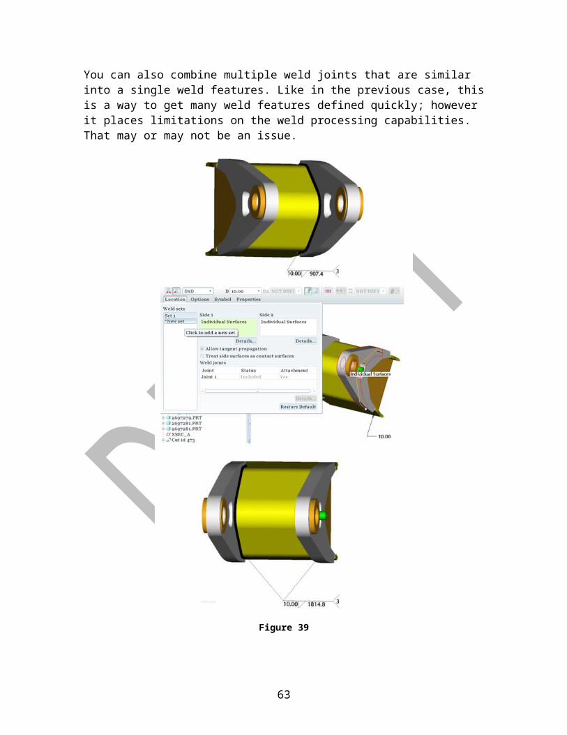
Figure 68
Once again, the mass properties will not change (assuming the weld cross section was defined using By Value and that value was the same in all three instances.
63

Associative Cross Sectional Weld AreaAs noted earlier in this guide, when you assign the weld cross-sectional area using the By Value method, there is a risk of that value being wrong, either due to miscalculation or from subsequent changes to the model. The following workaround is one technique that can be used to address this potential problem.
Figure 69
It is understood that all weld volumes are approximations due to changes in casting profiles, the variability associated with weld deposition, and the simple fact that weld size can vary within a tolerance range, so even if you take the trouble to define a relation such as this, the weld volume (and mass) are still only approximations. The purpose of this is just to save the engineer the trouble of calculating the area in an area where the geometry might be complex and to ensure that the area updates if design changes come along later.
64
Combining Similar WeldsJust like on the detailing side of Pro/E, we can combine welds of a similar type such that a single weld symbol point to both instances.
Figure 70
You can select the weld features to combine either from the display or from the Model Tree. Note that the weld length shown in the combined symbol is only the length of each one of the instances, not the total combined length.
Figure 71
65

Tail WeldsAs described in 1E0099: “Tail welds are extensions of fillet welds onto a plate to improve fatigue strength. The height is specified as the height at the end of a length away from the joint, and the length is specified in a drawing note. Tail welds are meant to be continuous extensions of the fillet welds. Tail welds gradually taper from the height of the fillet weld to the specified height within the specified length.”
With the current version of Pro/E, you can define such a weld joint, and Pro/E does calculate the mass properties of the weld, however if the weld is defined using the ‘Surface Weld’ option, the weld joint is not displayed accurately. One other thing to note here is that the tapering of the weld size is not accounted for, so volume and mass for these joints will be reported oversized.
In the image below, you can see two identical 10mm fillet welds. The weld joint in the foreground has a 50mm extension on the left end of the joint. Note that the Length and Mass for the first fillet weld are both larger values that the second weld, which is what we would expect to see, but visually they are both identical.
Figure 72
66

If the ‘Light Weld’ option is used, then you can see that the extension of the weld is accurately portrayed. This problem was reported to PTC and should be addressed in a future build of Pro/E Wildfire 5.
Figure 73
67

Modeling Slot WeldsWhile not exactly complicated, for some reason this particular type of weld has always been a bit counterintuitive to define. Here is a quick explanation of the references that are required when building a Slot weld.
First, pick the icon for Plug/Slot Welds
Figure 74
Select the icon circled in Figure 74 . This allows you define the slot weld using the Base Surface and the Side Surfaces as your geometry references. In this example, the plate is 9mm thick, so we will define the slot weld to be 8mm thick. This means that the weld will be 8mm deep from the base surface.
Figure 75
The Base Surface is the geometry of the non-slotted component which will be welded (indicated in Figure 75). The Side Surfaces will be all of the ‘side wall’
68
surfaces of the slot. You will need to use the Control key in order to select multiple references here, or use the Details button to gather surfaces using the ‘Seed & Bounds’ technique.
Figure 76The results are shown in Figure 76. Note that the Slot weld is called a ‘Plug Weld’ in the Model Tree.
Figure 77
69
Downstream UsageInformation from the CAD model can be used to drive many downstream applications, thus removing the dependence on drawings and redundant data entry. Since the usage of weld features in the CAD model is in it’s infancy at Caterpillar, most of this work is still in the very early phases, but we do have a few options available right now.
Programmatic Data ExchangesThe ideal scenario would be for us to get everything we need out of native Pro/E, but even if we could convince PTC to customize their tools to suit all of our specific needs, the time required to get these enhancements is often unacceptable. Some external applications provide the ability to read in data from Pro/E directly, and in those cases it is relatively easy to pass weld feature data along. One example of this is the aPriori cost estimating software. If weld features exist in the CAD model, the aPriori software can automatically extract the data that it needs to calculate and assign a corresponding cost figure for that weld joint. At Caterpillar we use Pro/TOOLKIT to define linkages between the CAD models and other external applications when these interactions are not otherwise available. This is not an insignificant task and maintenance of these programs sometimes gets to be troublesome, but it does give us the ability to customize the base tool to provide added functionality to meet requirements demanded by Caterpillar users.
User-Defined Data ExchangesProgrammed data exchanges are relatively easy for the user, however these can be expensive and time consuming to develop. An alternative to this is setting up user-defined data exchanges. We have a limited ability set up communications with outside applications. These interactions can be one-way (exported from Pro/E only) or they can be two-way. Three techniques that can be used to interact with external applications include:
Weld Reports Excel Analysis Features MathCAD
Each of these methods will be highlighted in the following pages, but for a full explanation of the tools, please refer to
http://www.ptc.com/support/index.htm
70

Weld Reports
Pro/REPORT is an application mode within Pro/E that provides for the ability to generate associative tables of data on a 2D drawing sheet. These tables can be defined to display various bits of information about a welded assembly model. The tables are defined to a generic .tbl file, but when the table is inserted in the Report file and the model is referenced in the Report, the data in the table is automatically populated with the information that has been embedded in each weld feature. Shown in Figure 77 is an example of a typical customized Report table.
Figure 78
In this case all of the parameters are predefined to exist within Pro/E. We should be able to also include other pieces of user-defined information that may be included as part of the weld feature, such as number of passes, weld gas, etc.
71
Note: This capability (including user-defined parameters in Report Tables) is supposed to work, but was reported as non-functional on Oct 28, 2009. The call number with PTC is C7357280.

Once the Report file has been created and the desired table has been included and populated with weld feature data, the information in the table can be exported out of Pro/E as a text file or as a comma delimited file that is easily read into a spreadsheet.
Figure 79
This technique is only a one-way data exchange. You can export data out of Pro/E so that the data used outside of Pro/E is in sync with the CAD model. The limitations with this method are:
a) The kinds of data that are valid for export are limitedb) You cannot change that data and update the model or use that data to
generate new data to be stored back into the CAD model
The first limitation has been reported to PTC as a software issue. The second limitation may be addressed with the following types of User-Defined data exchange methods.
72
Excel Analysis FeaturesAnother possible way to get weld feature data out of Pro/E and make it available for manipulation with an external application is by using the Excel Analysis feature. In this simple example, weld joint sizes and weld process data tied to weld features in the CAD model are exported from Pro/E via the Excel Analysis feature. Outside of Pro/E an Excel spreadsheet is defined to read in the data from Pro/E. Inside Excel calculations are performed and data is retrieved from a table. The calculations and retrieved data are automatically fed back into Pro/E.
Figure 81
73
Figure 80

MathCADA few years ago PTC acquired ownership for this third party software application. If licensed to run MathCAD from your computer, you can access it directly within the Pro/E environment. MathCAD allows you to define mathematical equations and tie these equations with the CAD model, much like you could do with Excel Analysis features, but MathCAD is much more developed specifically for this purpose.
Some of the advantages of using MathCAD are:
clarity of notation (readability)
clarity of dependencies (verification)
unit analysis (error checking)
breadth of calculation tools (completeness)
Engineering-appropriate graphs, image analysis, matrix analysis, and data
support
Complex equations can be written that use information from the CAD model and return modified data, or generate new data that can be sent back into Pro/E in the form of a parameter. You can also utilize predefined equations already embedded within MathCAD. The complete 6th edition of Roark’s Formulas for Stress and Strain is included within the MathCAD environment, containing more than 1,000 separate design cases covering straight beams and bars, curved beams, plates and shells. Also included are all 37 tables of formulas from Roark’s and dozens of detailed example problems worked out in MathCAD so this is another good option for reusing weld data for design optimization.
74
Figure 82
Future Directions For Downstream UsageAt this point in time we have a few options for driving downstream applications with weld features in the CAD model as discussed earlier. We are currently limited by the functions provided in Wildfire 5, the ability of external applications to read in Pro/E data and use it, and the limitations of the Pro/TOOLKIT, but the potential for reusing the weld data is promising. We have already used simple test case Pro/E models with weld features to simulate weld distortion and are working with the software provider to develop improvements within MECHANICA Thermal so that we can quickly visualize and quantify the effects of a moving heat source in the CAD environment.
The current version of WPM uses 2D information from Pro/E to help define and communicate welding processes. In the future we could be pulling the logic for defining the welding processes into the CAD model and using that information for other applications, eliminating the need to re-enter data in other applications.
Weld sizing at this time basically consists of using rules of thumb or rigorous FEA studies to come up with weld size callouts. Oversized welds can be a big contributor to unnecessary cost as well as quality problems stemming from distortion. Down the road we could tools embedded tools which are used to come up with initial weld sizes and optimize on things like manufacturability, cost, weight, etc.
We can currently export Pro/E models with weld features as lightweight ‘models’ to be used by shop personnel as instructional aids for setting up tooling and robots. While these images are currently simple 3D images with no embedded parametric data tied to the weld features, these intelligent models will become available in the future.
Software used at Caterpillar for plant layout could very well be gathering information about welded components directly from the Pro/E models as input for optimization of factory layouts. Modifying designs and welding procedures could quickly help to build business plans for capital expenditures.
Today we import CAD geometry and programmers refer to detailed drawings and weld procedures as input for defining off-line robot welding programs. In the coming years we plan to work with the CAD supplier and OLP software vendors so that the programmers may use the weld features directly out of the Pro/E model and drastically reduce the time required to create new programs or make changes to existing ones when design changes occur.
While we still have a long way to go, we can see that the potential for using the weld features in our CAD models as well as the importance of having these features fully defined in the model as opposed to continuing to rely on 2D weld symbols in drawings.
75
Appendices
Appendix A: Weld-related config.pro optionsweld_ui_standard … Specifies weld standard to be either ANSI or ISO[Suggested setting –> ANSI]
add_weld_mp … Specifies whether welds are included when calculating mass properties[Suggested setting –> YES]
pro_weld_params_dir … Directory where Pro/ENGINEER searches when looking for weld parameter files
weld_ask_xsec_refs … Specifies whether x-section references are asked for when creating weld features
weld_color … Defines weld feature color[Suggested setting –> 0, 0, 0 … this results in a weld color of solid black for Surface type weld features]
weld_dec_places … Number of decimal places to display in weld parameters
weld_edge_prep_driven_by … Specifies if the edge preparation feature is created at the part level or the assembly level
weld_edge_prep_groove_angle … Default value for angle cut value
weld_edge_prep_groove_depth … Default value for edge preparation depth
weld_edge_prep_instance … Determines whether a family table instance is created automatically for edge preparation
weld_edge_prep_name_suffix … Specifies suffix name for family table instances created during edge preparation
weld_edge_prep_root_open … Default value for edge preparation root opening
weld_edge_prep_visibility … Specifies visibility for edge preparation features for generic and instances
76
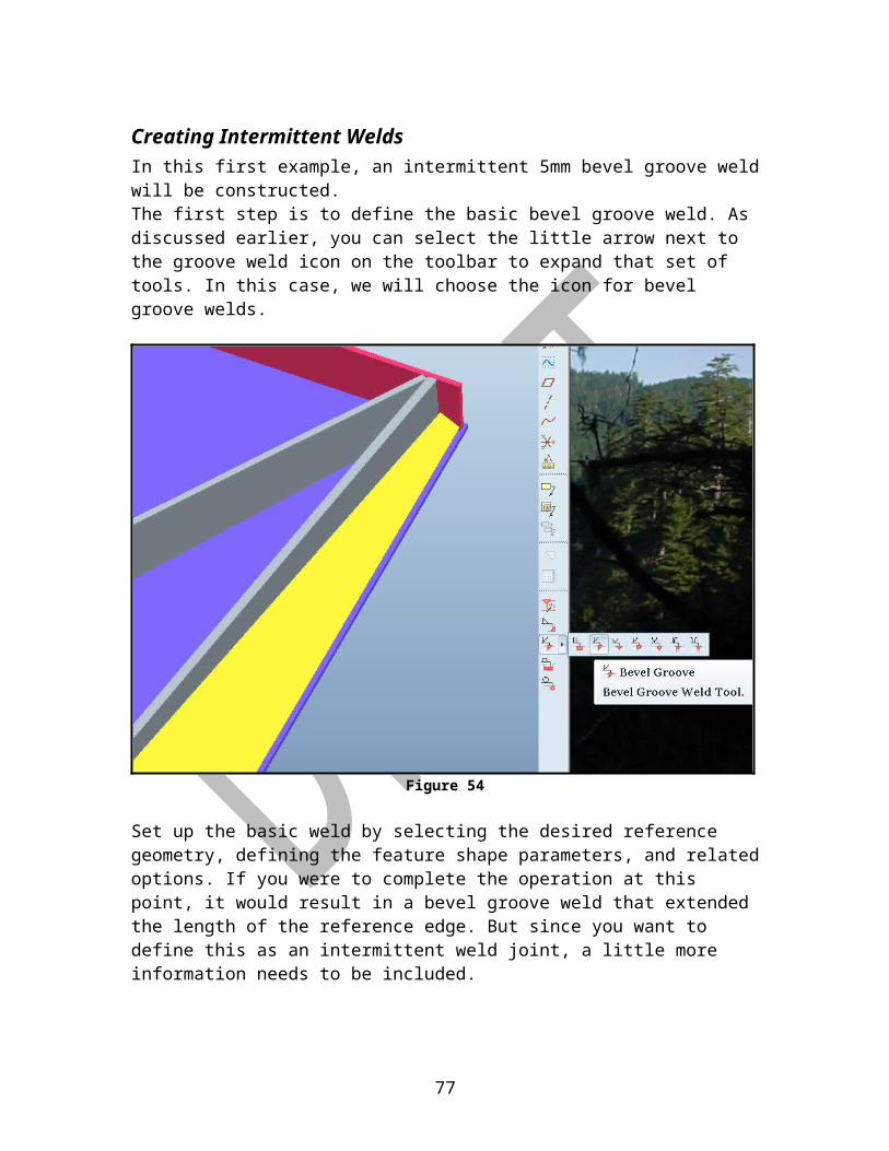
Figure 77 shows a set of welding configuration options that were used to build most of the models shown in this User Guide. In this example, a folder has been set up to hold all of the preferences files (C:\home\ProE_Weld_Configs). In an actual production facility installation, this would probably be stored to a central library location where all users could use these predefined files and a set of super-users would have the ability to author and save changes to the library.
Figure 83
77
Appendix B: Welding ParametersThis is the list of pre-defined system welding parameters. These parameters are created automatically and loaded with the corresponding values as a particular weld feature or weld process is created.
78
Figure 84
Appendix C: Suggested Weld Preferences SettingsBy defining weld preference files and declaring them in the config.pro file, default values for commonly used weld features can be pre-set, making it much easier to build complete weld features from these templates. You may need to go in and modify some of the information, but much of it will be loaded with at least a reasonable value.
Figure 79 shows the settings for a typical general weld preferences file. This file would typically be created once then saved to a location called out in the config.pro with the following entry:
Figure 85
79

Figure 80 shows a typical preference file setup for fillet welds.
Figure 86
Once the weld fillet preference file has been set, it can be saved to a common folder and the location saved in the config.pro file with a line like this:
80

Likewise, Figure 81 shows a typical preference file setup for groove welds. Note that there is currently no option for declaring any distinctions for different kinds of groove welds. This limitation was presented to PTC in the form of a software enhancement request (tracking number E7394437) in November, 2009.
Figure 87
81

Appendix D: Suggested Layer Rules In the section of this guide dealing with layers for welds, it was mentioned that weld quilts and weld symbol annotations should be placed on two specific layers. This can be automated by including these two layers with a set of predefined Layer Rules for each.
The Layer Rule for the 10__WELD can be defined with the following settings:
Figure 88
There should be two Layer Rules for the 11__WLD_SYM layer. These are defined with the following settings:
Figure 89
82