Embed Size (px)
Citation preview
MEM
ERA
250
A comprehensive range of protective devices and
accessories to complement both the Memera 2000
and Memera 2000 AD consumer unit range.
PROTECTIVEDEVICES &ACCESSORIES
Ancillary devices 253-254
Contactors andimpulse relays 253
Enclosures 255
HRC fuse modules 252
Isolators 253
Miniature circuitbreakers 251
Reversed pole RCCB 252
RCCB’s 253
RCBO’s 253
SP & N switchfuses 256
Timers 254
MEM
ERA
251
PROTECTIVE DEVICES Consumer unit devices
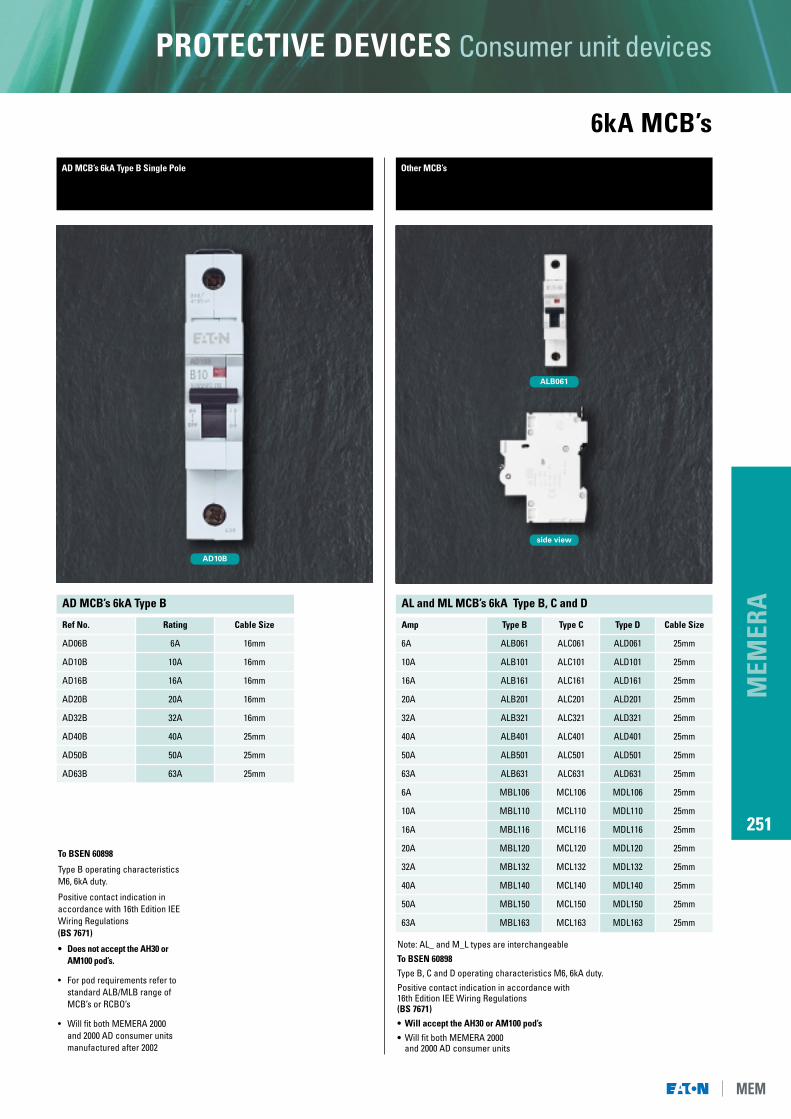
6kA MCB’sOther MCB’s
ALB061
side view
AD MCB’s 6kA Type B Single Pole
AD10B
To BSEN 60898
Type B operating characteristicsM6, 6kA duty.
Positive contact indication inaccordance with 16th Edition IEEWiring Regulations(BS 7671)
• Does not accept the AH30 or AM100 pod’s.
• For pod requirements refer tostandard ALB/MLB range of MCB’s or RCBO’s
• Will fit both MEMERA 2000and 2000 AD consumer units manufactured after 2002
AD MCB’s 6kA Type B
Ref No. Rating Cable Size
AD06B 6A 16mm
AD10B 10A 16mm
AD16B 16A 16mm
AD20B 20A 16mm
AD32B 32A 16mm
AD40B 40A 25mm
AD50B 50A 25mm
AD63B 63A 25mm
AL and ML MCB’s 6kA Type B, C and D
Amp Type B Type C Type D Cable Size
6A ALB061 ALC061 ALD061 25mm
10A ALB101 ALC101 ALD101 25mm
16A ALB161 ALC161 ALD161 25mm
20A ALB201 ALC201 ALD201 25mm
32A ALB321 ALC321 ALD321 25mm
40A ALB401 ALC401 ALD401 25mm
50A ALB501 ALC501 ALD501 25mm
63A ALB631 ALC631 ALD631 25mm
6A MBL106 MCL106 MDL106 25mm
10A MBL110 MCL110 MDL110 25mm
16A MBL116 MCL116 MDL116 25mm
20A MBL120 MCL120 MDL120 25mm
32A MBL132 MCL132 MDL132 25mm
40A MBL140 MCL140 MDL140 25mm
50A MBL150 MCL150 MDL150 25mm
63A MBL163 MCL163 MDL163 25mm
Note: AL_ and M_L types are interchangeableTo BSEN 60898
Type B, C and D operating characteristics M6, 6kA duty.Positive contact indication in accordance with 16th Edition IEE Wiring Regulations(BS 7671)
• Will accept the AH30 or AM100 pod’s
• Will fit both MEMERA 2000and 2000 AD consumer units
MEM
ERA
252
PROTECTIVE DEVICES Consumer unit devices
side view
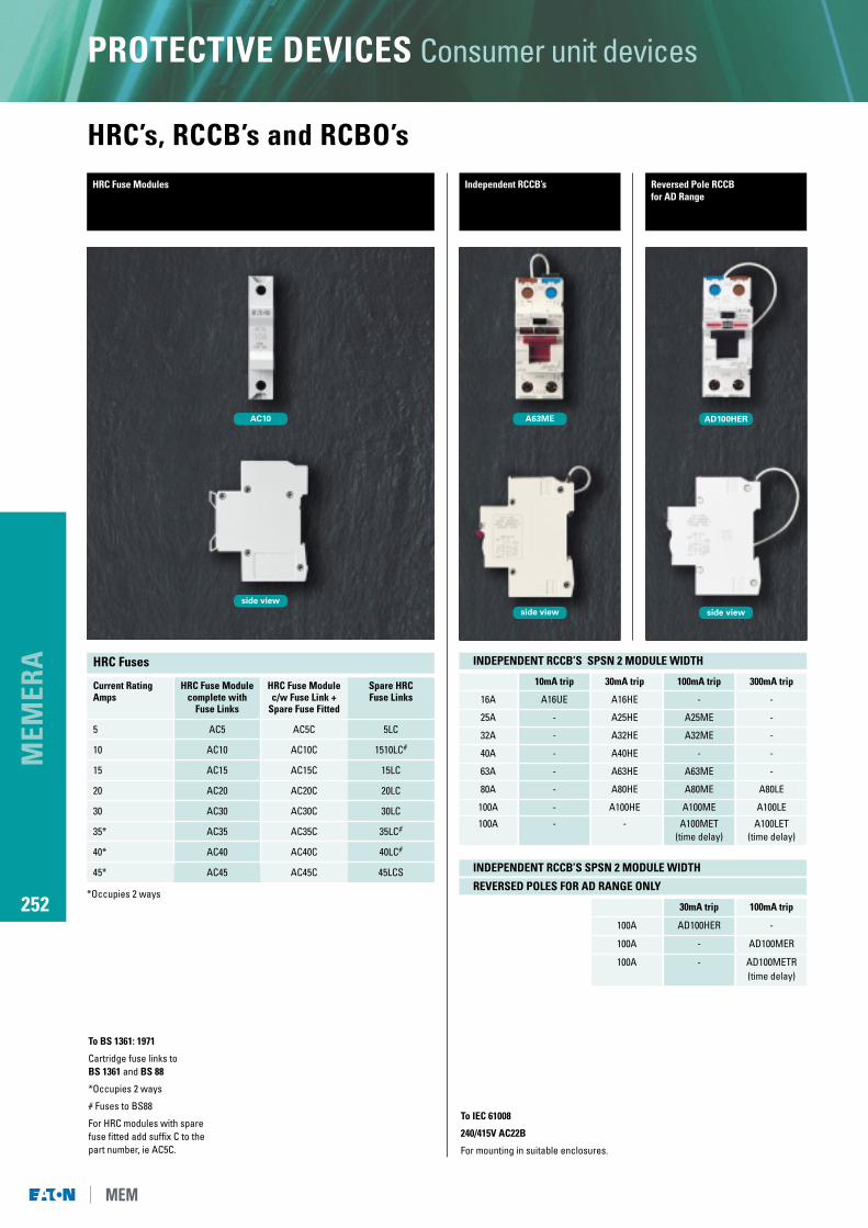
HRC Fuse Modules
AC10
To BS 1361: 1971
Cartridge fuse links toBS 1361 and BS 88
*Occupies 2 ways
# Fuses to BS88
For HRC modules with spare fuse fitted add suffix C to the part number, ie AC5C.
HRC’s, RCCB’s and RCBO’sIndependent RCCB’s Reversed Pole RCCB
for AD Range
AD100HER
side view
A63ME
side view
To IEC 61008
240/415V AC22B
For mounting in suitable enclosures.
INDEPENDENT RCCB’S SPSN 2 MODULE WIDTH
REVERSED POLES FOR AD RANGE ONLY
INDEPENDENT RCCB’S SPSN 2 MODULE WIDTH
30mA trip 100mA trip
100A AD100HER -
100A - AD100MER
100A - AD100METR(time delay)
10mA trip 30mA trip 100mA trip 300mA trip
16A A16UE A16HE - -
25A - A25HE A25ME -
32A - A32HE A32ME -
40A - A40HE - -
63A - A63HE A63ME -
80A - A80HE A80ME A80LE
100A - A100HE A100ME A100LE
100A - - A100MET A100LET(time delay) (time delay)
HRC Fuses
Current Rating HRC Fuse Module HRC Fuse Module Spare HRCAmps complete with c/w Fuse Link + Fuse Links
Fuse Links Spare Fuse Fitted
5 AC5 AC5C 5LC
10 AC10 AC10C 1510LC#
15 AC15 AC15C 15LC
20 AC20 AC20C 20LC
30 AC30 AC30C 30LC
35* AC35 AC35C 35LC#
40* AC40 AC40C 40LC#
45* AC45 AC45C 45LCS
*Occupies 2 ways
MEM
ERA
253
PROTECTIVE DEVICES Consumer unit devices
Isolators/Contactors and Relays
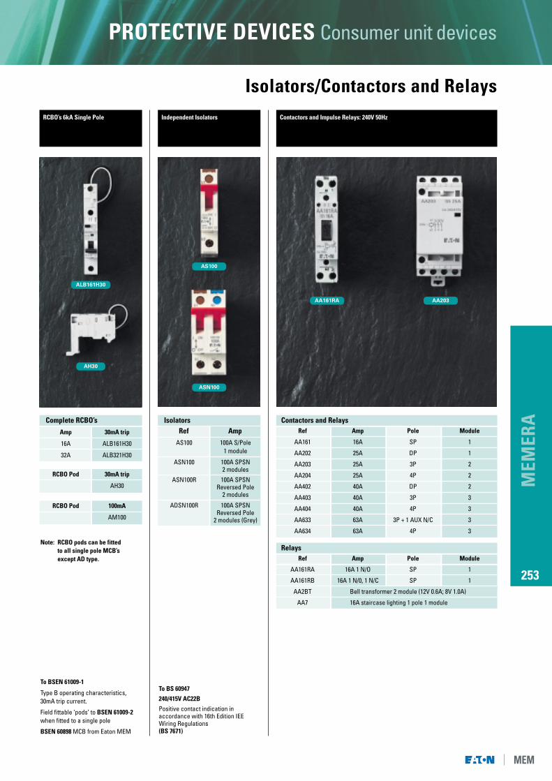
AA161RA AA203
AS100
ASN100
Independent Isolators Contactors and Impulse Relays: 240V 50Hz
To BS 60947
240/415V AC22B
Positive contact indication inaccordance with 16th Edition IEEWiring Regulations(BS 7671)
Contactors and Relays
Relays
Ref Amp Pole Module
AA161 16A SP 1
AA202 25A DP 1
AA203 25A 3P 2
AA204 25A 4P 2
AA402 40A DP 2
AA403 40A 3P 3
AA404 40A 4P 3
AA633 63A 3P + 1 AUX N/C 3
AA634 63A 4P 3
Ref Amp Pole Module
AA161RA 16A 1 N/O SP 1
AA161RB 16A 1 N/0, 1 N/C SP 1
AA2BT Bell transformer 2 module (12V 0.6A; 8V 1.0A)
AA7 16A staircase lighting 1 pole 1 module
AS100 100A S/Pole1 module
ASN100 100A SPSN2 modules
ASN100R 100A SPSNReversed Pole
2 modules
ADSN100R 100A SPSNReversed Pole
2 modules (Grey)
IsolatorsRef Amp
RCBO’s 6kA Single Pole
AH30
ALB161H30
To BSEN 61009-1
Type B operating characteristics,30mA trip current.
Field fittable ‘pods’ to BSEN 61009-2when fitted to a single pole
BSEN 60898 MCB from Eaton MEM
Amp 30mA trip
16A ALB161H30
32A ALB321H30
RCBO Pod 30mA trip
AH30
RCBO Pod 100mA
AM100
Complete RCBO’s
Note: RCBO pods can be fittedto all single pole MCB’s except AD type.

MEM
ERA
254
PROTECTIVE DEVICES Consumer unit devices
Timers and AccessoriesTimers Accessories
AL1
PD2
AL2
ABP1
AL3
AET1
AT1SD AT2P
AT1SW
Timers Analogue Analogue DigitalSynchronous Quartz Quartz
Descriptions Stabilised
24hr, 1 channel, 3 modules AT1SD AT1QD -
24hr, 1 channel, 1 module AT11SD - -
7 day, 1 channel, 3 modules AT1SW AT1QW -
Fully programmable, 1 channel, 1 module - - AT11P
Fully Programmable, 1 channel, 2 modules - - AT1P
Fully Programmable, 2 channel, 2 modules - - AT2P
Minimum Programmable time, day/week 30min/3hr 30min/3hr 1min
Running reserve recharge time - 150hr/70hr 100hr/140hr
AL1 Locking device for isolators
AL2 Locking device for MCB’s
AL3 Locking device for RCCB’s
PD2 Padlock for locking devices/enclosure doors
ABP1 1 way unit blanking plate
AET1 Earth link kit (25mm2)
ADKIT Spare busbar and way label
Accessories

MEM
ERA
255
PROTECTIVE DEVICES Consumer unit devices
Moulded and Metalclad Enclosures
A2SL AN4EBLS AN2ST4QEL
Enclosures
Enclosure ranges available
A2SL Moulded 2 165 62 88 55 no Sealable terminal access
A2SLE Moulded 2 165 62 88 55 yes Sealable terminal access
A2SL/ Moulded 2 165 62 88 55 yes 6A DP MCB fittedALB062 Sealable terminal access
Product Finish No. of Modules Dimensions (mm) IP Rating Earth Bar Additional features
Ref No. H W D
3QEL Moulded 2-3 134 174 97 55 no Blank plates provided
4QEL Moulded 2-4 170 105 112 55 no Blank plates provided
6QEL Moulded 1-6 170 135 112 55 no Blank plates provided
Product Finish No. of Modules Dimensions (mm) IP Rating Earth Bar Additional features
Ref No. H W D
AN2ST Metalclad 2 186 105 72 40 yes N/A
AN4S Metalclad 4 206 145 90 40 yes Plastic front cover fitted
Product Finish No. of Modules Dimensions (mm) IP Rating Earth Bar Additional features
Ref No. H W D
AN2 Moulded 2 135 40 65 40 no Sealable terminal access
AN2D Moulded 2 135 40 65 40 no ASN100 SPSN isolator fitted
AN25 Moulded 2 135 50 65 40 yes Earth bar fittedSealable terminal access
*AN2EBD Moulded 2 135 40 65 40 no AD100 SPSN isolator fitted#AN4EBLS Moulded 4 135 110 88 40 no Lockable cover
4EME Moulded 4 135 89 60 40 yes Steel DIN rail fitted
Product Finish No. of Modules Dimensions (mm) IP Rating Earth Bar Additional features
Ref No. H W D
Above items complete with sealable transparent cover
*Sealable supply terminal access, independent access to load terminals#Independent top and bottom sealable terminal access.

MEM
ERA
256
PROTECTIVE DEVICES Consumer unit devices
SP & N Switchfuses
604R
1000KMF
SP & N Switchfuses
800KMF
804R
Each 1000KMF unit is IP41 rated with a 100A double pole isolating switch rated at240V AC only, fitted as standard. Complying to BSEN 60947-3 with a conditional shortcircuit current rating of 16kA and utilisation category AC22, 240V. Units are suppliedwith fuselinks to BS 88 Part 2 designed for offset contact. The moulded fuse unit isshrouded to prevent accidental contact with live parts.
SP & N SwitchfuseRef Rating Finish HRC Amp Standard
800KMF 80A Moulded 80A BS 1361
800KMFNF 80A Moulded no -
1000KMF 100A Metalclad 100A BS 88
1000KMF-80 100A Metalclad 80A BS 88
Ref HRC Amp Standard
80RFK 80A BS 88
100RFK 100A BS 88
1000KMF - Maximum cable sizes are:- Incoming cables 50mm2, outgoing cables 35mm2.
800KMF - Maximum cable sizes are:- Main terminals 25mm2, earth terminal 16mm2.
Replacement fuse link and holder for 1000KMF
Ref
AL1
Locking Device for DP isolator
Ref
PD2
Padlock & key for AL1
Ref Amp Standard
454R 45A BS 1361
504R 50A BS 1361
604R 60A BS 1361
804R 80A BS 1361
Moulded Cable Gland for 800KMF
Ref
1MGL
HRC Fuselink for 800KMF
D90mm 196mm
296mm
W
134mm CTRS
208mmH
1000KMF Dimensions
1000KMF
800KMF Dimensions
Maximum cable sizes are:- 50mm2, outgoing cables 35mm2.
Maximum cable sizes are:- Main terminals 25mm2, Earth terminal 16mm2.
80mm
127mm 66mmDW
H
Complying with BSEN 60947-3 for duty AC22B, 240V AC.
Compact SP & N moulded switchfuse rated at 80A and fitted with pull out HRC fuselink. Accommodates fuse links to BS 1361 (45-80A)

MEM
ERA
257
PROTECTIVE DEVICES Consumer unit devices
Switchgear Technical Data
1000050004000
2000
1000600400
200
1006040
20
1064
2
10,60,4
0,2
0,1
0,04
1
0,02
0,010,006
1,5 2 3 4 8 9 10 1,5 20 30 40
multiples of In
time
in s
econ
ds
1000050004000
2000
1000600400
200
1006040
20
1064
2
10,60,4
0,2
0,1
0,04
1
0,02
0,010,006
1,5 2 3 4 8 9 10 1,5 20 30 40
multiples of In
time
in s
econ
ds
1000050004000
2000
1000600400
200
1006040
20
1064
2
10,60,4
0,2
0,1
0,04
1
0,02
0,010,006
1,5 2 3 4 8 9 10 1,5 20 30 40
multiples of In
time
in s
econ
ds
TYPE B TYPE C TYPE D
Eaton’s MEM miniature circuit breakers (MCB’s) aremanufactured to - BSEN 60898. They have amaximum breaking capacity of 6kA and areavailable in a selection of current ratings from 6A to63A. The maximum cable capacity being 16mm2 upto32A and 25mm2 to 40A-63A.
Note: Maximum cable capacity 16mm2
for AD range up to 32A.
The MCB’s are suitable for 240V, AC, 50/60Hzsystems and are calibrated at 40°C. All of the MCBratings available are single module width.
AL/ML range MCB’s are also available for use whenfield fitted pod mounted RCBO’s are required.
Miniature Circuit Breakers
Characteristics and Applications for MCB Types
Type B: suitable for domestic and commercialinstallations having little or no switching surges.
Type C: general use in commercial/industrialinstallations where the use of fluorescentlighting, small motors etc. can produceswitching surges.
Type D: for use with equipment such as transformers,some fluorescent lighting, X-ray machines,industrial welding equipment and similarapplications where very high inrush currentsare experienced.
BS 7671: 2001 requirements for Electrical installations (16th Edition of the IEE Wiringregulations) specifically identifies Type B & Type C. Lower earth fault loopimpedance’s (Zs) are generally necessary for Type D to achieve the operating timesrequired by regulation 413-02-08. (Maximum Zs is calculated using the formula in theregulations and the characteristics of the circuit breaker).
Where the requirement cannot be achieved, use of the circuit breakers asovercurrent protective devices is not precluded, but the use of residual current circuitbreakers (RCCB’s) to provide protection against indirect earth fault condition isimplied. Establishment of the value of the earth fault loop impedance (Zs) at the designstage of installation will determine which type of the circuit breakers should be used.
BS EN Instantaneous Typical Eaton MEM MCB60898 Trip Current Application PrefixTYPE Range (xIn)
B 3 to 5 Domestic ALB/MBL
C 5 to 10 Commercial ALC/MCLLight Industrial
D 10 to 20 General Industrial ALD/MDL
Note: IEC 898 permits the upper limit for type D to extend to 50 x In.
OPERATING CHARACTERISTICS FOR AD DOMESTIC RANGE OF TYPE B MCCB’S
MCB OPERATING CHARACTERISTICS
BS EN Instantaneous Typical Eaton’s MEM MCB60898 Trip Current Application PrefixTYPE Range (xIn)
B 3 to 5 Domestic AD
OPERATING CHARACTERISTICS FOR AL/ML RANGE OF MCB’S

MEM
ERA
258
PROTECTIVE DEVICES Consumer unit devices
Switchgear Technical Data
86
4
2
86
4
2
86
4
2
86
4
2
86
4
2
86
4
2
86
2 4 6 8 2 4 6 8 2 4 6 8 2 4 6 8 2 4 6 8
10 1
10 1
1
10 2
10 3
10 4
10 5
10 6
10 2 10 3 10 4 10 5
PROSPECTIVE CURRENT (amps)
PRE A
RCHI
NG TI
ME (
seco
nds)
5 15 20 4530
TIME CURRENTCHARACTERISTIC
CURVES FOREATON’S MEM
HRC FUSE-LINKSList No’s
5LC, 15LC,20LC,30LC & 45LCS.
Maximum Earth fault loop impedance ie Zs ohms for circuits supplying socket outletsin accordance with BS 7671 regulation 413-02-08 at 240V.
Earth fault loop impedance’s (Zs) to give compliance with BS 7671 regulation 413-02-08 at 240V
HRC FUSE OPERATING CHARACTERISTICS
At these levels of earth loop impedence, fuses and MCB’s will provide disconnection times inaccordance with BS 7671 for circuits supplying socket outlets (and fixed bathroom equipment).
Device Standard 5A 6A 10A 15A 16A 20A 30A 32A 35A 40A 45A 50A 63A
HRC Fuselink BS88/1361 10.90 8.89 5.33 3.43 - 1.78 1.20 - - 0.86 0.60 - -
Type B MCB BS EN 60898 - 8.00 4.80 - 3.00 2.40 - 1.50 - 1.20 - 0.96 0.76
Type C MCB BS EN 60898 - 4.00 2.40 - 1.50 1.20 - 0.75 - 0.60 - 0.48 0.38
Type D MCB BS EN 60898 - 2.00 1.20 - 0.75 - - 0.38 - 0.30 - 0.24 0.19

MEM
ERA
259
PROTECTIVE DEVICES Consumer unit devices
Switchgear Technical DataResidual current circuit breakers (RCCB)
(RCCB) selection chart
When must an RCCB be used BS 7671 (16th Edition IEE regs.)
i) TT supply (471-08-06)
ii) Sockets to supply portable equipmentoutside the equipotential zone (471-16-01)
iii) Supply to caravan (608-13-05)
Current operated RCD’s provide a high degree of protection against electrocution and fire risk due to electrical faults.
Explanation of abbreviations used
R.C.D. Residual Current Device is the generic termcovering the range of devicesincorporating sensing of residual currentsand includes within it’s scope R.C.C.B. andR.C.B.O. type products.
R.C.C.B. Residual Current Circuit Breaker is anRCD which will cause disconnection ofelectrical supply should a residual currentpassing through the device exceed aspecified load.
R.C.B.O. Residual Current Circuit Breaker withoverload protection is an RCD which willcause disconnection of electrical supplydue to residual current exceeding specifiedlimits together with integral overload;overcurrent and short circuit protectionassociated with a miniature circuit breaker.
To BS 4293. IEC 61008 also BS EN 61008. AC22B Duty. For mounting in suitable enclosures.
Trip Current (mA)
10 30 100 300 300
TIME DELAY
RATING(A)
2 Pole 2 Module
16 A16UE A16HE
25 A25HE A25ME
32 A32HE A32ME
40 A4OHE
63 A63HE A63ME
80 A8OHE A8OME
100 A1OOHE A1OOME A1OOLE A1OOLET
MEM
ERA
260
PROTECTIVE DEVICES Consumer unit devices
Switchgear Technical Data
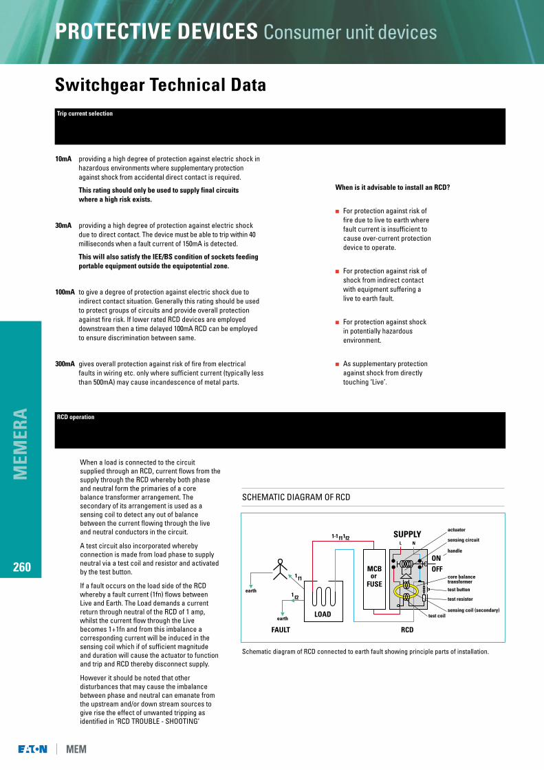
10mA providing a high degree of protection against electric shock inhazardous environments where supplementary protectionagainst shock from accidental direct contact is required.
This rating should only be used to supply final circuits where a high risk exists.
30mA providing a high degree of protection against electric shockdue to direct contact. The device must be able to trip within 40milliseconds when a fault current of 150mA is detected.
This will also satisfy the IEE/BS condition of sockets feedingportable equipment outside the equipotential zone.
100mA to give a degree of protection against electric shock due toindirect contact situation. Generally this rating should be usedto protect groups of circuits and provide overall protectionagainst fire risk. If lower rated RCD devices are employeddownstream then a time delayed 100mA RCD can be employedto ensure discrimination between same.
300mA gives overall protection against risk of fire from electricalfaults in wiring etc. only where sufficient current (typically lessthan 500mA) may cause incandescence of metal parts.
Trip current selection
When a load is connected to the circuitsupplied through an RCD, current flows from thesupply through the RCD whereby both phaseand neutral form the primaries of a corebalance transformer arrangement. Thesecondary of its arrangement is used as asensing coil to detect any out of balancebetween the current flowing through the liveand neutral conductors in the circuit.
A test circuit also incorporated wherebyconnection is made from load phase to supplyneutral via a test coil and resistor and activatedby the test button.
If a fault occurs on the load side of the RCDwhereby a fault current (1fn) flows betweenLive and Earth. The Load demands a currentreturn through neutral of the RCD of 1 amp,whilst the current flow through the Livebecomes 1+1fn and from this imbalance acorresponding current will be induced in thesensing coil which if of sufficient magnitudeand duration will cause the actuator to functionand trip and RCD thereby disconnect supply.
However it should be noted that otherdisturbances that may cause the imbalancebetween phase and neutral can emanate fromthe upstream and/or down stream sources togive rise the effect of unwanted tripping asidentified in ‘RCD TROUBLE - SHOOTING’
RCD operation
When is it advisable to install an RCD?
� For protection against risk of fire due to live to earth where fault current is insufficient to cause over-current protectiondevice to operate.
� For protection against risk of shock from indirect contactwith equipment suffering alive to earth fault.
� For protection against shockin potentially hazardousenvironment.
� As supplementary protectionagainst shock from directlytouching ‘Live’.
Schematic diagram of RCD connected to earth fault showing principle parts of installation.
L N
MCBor
FUSE
LOAD
FAULT RCD
test coilsensing coil (secondary)
test resistor
core balance transformer
ONOFF
handle
sensing circuit
actuatorSUPPLY
test button
1 f1
1 f2
1+1 f11f2
earth
earth
SCHEMATIC DIAGRAM OF RCD

MEM
ERA
261
PROTECTIVE DEVICES Consumer unit devices
Switchgear Technical DataResidual current circuit breaker with overload protection (R.C.B.O.)
RCBO
The functionality of a standard MCB is maintained but with the added flexibility of residual currentprotection. Eaton’s MEM RCBO’s all comply to the latest standard BS EN 61009-1.
The RCBO ‘pod’ device can be fitted in situ to any single pole BS EN 60898 MCB from Eaton’s MEM ranges, other than the standard AD range.
Loss of Supply Neutral
Under loss of supply neutral conditions, the R.C. elementof the device will continue to provide earth leakageprotection. With these conditions and upon detection ofan earth leakage current the RCBO will operate within itsnormal characteristics.
D.C. Components in the Load
The RCBO is capable of responding to the superimposedDC current in compliance with BS EN 61009. eg. fault condition on equipment using rectified voltages.
Surge/Transient Suppression
Surge/Transient Suppression is incorporated within theunit and is therefore suitable for use with supplyequipment susceptible to such mains borne transients.(Within EMC tolerances).
RATING(A) REF. Trip Current (MA)
16 ALB161H30 30
32 ALB321H30 30
Pod Only AH30 30
Pod Only AM100 100
SUPPLY
LOAD
L R
L N
R
T
ON
OFF
INCOMING(non protected upstream of RCD)
Loose connections
Mains borne disturbance (effect worse off load)exceeding EMC Std EN50082-1
Site machinery / plantInstalled services
lightning strike
etc...
OUTGOING
Mains borne (effect worse off load) (exceeding EMC Std En50082-1)
Wrongly specified Loose connections
Incorrect application Wet plaster
No discrimination btwn RCD’s Condensation (i.e. behind Appliances)
Crossed neutral on split load Mineral-insulated conductors
N to E fault on non PME (trips) Heating elements (new or old)
N to E fault on PME (no trip) Household faults (picture hooks etc)
High standing earth leakage Moisture ingress (appliance scks etc)
Appliances & installed services etc...
SCHEMATIC DIAGRAM OF RCD INCLUDING CAUSES OF SPASMODIC TRIPPING
MEM
ERA
262
PROTECTIVE DEVICES Consumer unit devices
Switchgear Technical DataRCD troubleshooting diagram
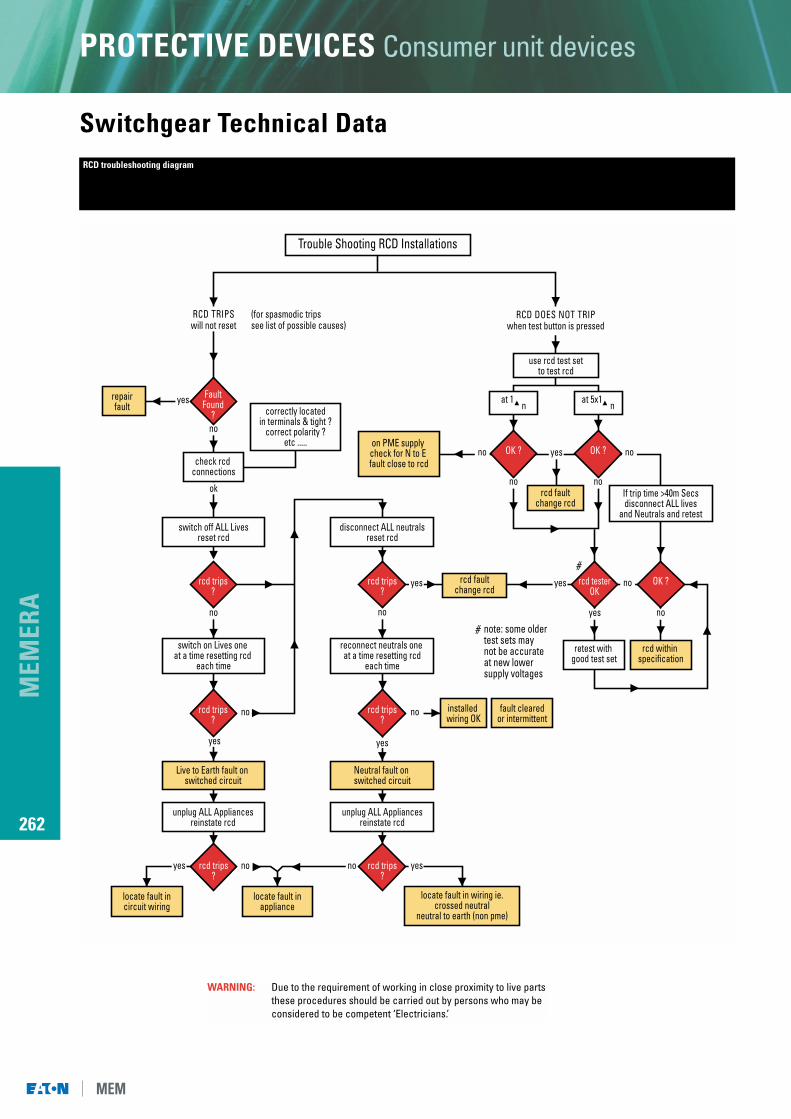
Trouble Shooting RCD Installations
RCD TRIPSwill not reset
RCD DOES NOT TRIPwhen test button is pressed
rcd trips?
Live to Earth fault on switched circuit
locate fault incircuit wiring
locate fault inappliance
locate fault in wiring ie.crossed neutral
neutral to earth (non pme)
unplug ALL Appliancesreinstate rcd
Neutral fault on switched circuit
installed wiring OK
retest with good test set
rcd within specification
rcd faultchange rcd
rcd faultchange rcd
at 5x1 n
fault clearedor intermittent
unplug ALL Appliancesreinstate rcd
repairfault correctly located
in terminals & tight ?correct polarity ?
etc .....
switch off ALL Livesreset rcd
disconnect ALL neutralsreset rcd
on PME supply check for N to E fault close to rcd
use rcd test setto test rcd
switch on Lives one at a time resetting rcd
each time
reconnect neutrals one at a time resetting rcd
each time
note: some older test sets maynot be accurateat new lowersupply voltages
If trip time >40m Secsdisconnect ALL lives
and Neutrals and retest
at 1 n
(for spasmodic tripssee list of possible causes)
yes
yes
yes
yes
yes
yes yes
yes
no no
yes
no
nono
no no
ok
no
no no
no
no
no
FaultFound
?
OK ? OK ?check rcd
connections
rcd trips?
rcd trips?
rcd trips?
rcd trips?
rcd trips?
OK ?rcd testerOK
#
#
WARNING: Due to the requirement of working in close proximity to live partsthese procedures should be carried out by persons who may beconsidered to be competent ‘Electricians.’

MEM
ERA
263
PROTECTIVE DEVICES Consumer unit devices
Switchgear Technical DataTechnical information - modular contactor range for selection for heating and motor control circuits
Maximum Power in kW according to electrical durability
Heating Circuits Motor Control Circuits
Electrical durability contactor 230v single-phasein opening cycles 100x103 150x103 200x103 500x103 106 rating capacitor motor (2 pole)
Single Phase 3.5 3 2.2 1 0.8 16A 0.55
Switching 5.4 4.6 3.5 1.6 1.2 25A 1.1
230V 8.6 7.4 3.5 1.6 1.2 40A 2.2
(2 pole) 13.6 11.6 8.8 4 3 63A 4
HeatingSingle-phase, 2-pole switching
Motor ControlSingle-phase circuit 230V
m
U
V
L1
L2
Technical information - modular time switch range
Other modular devices
Impulse Relay Contactor
Reference AA161RA AA161RB AA161 AA202 AA203 AA204 AA402 AA403 AA404 AA633 AA634
Contact Configuration 1N/O 1N/O, 1N/C 1N/O, 1N/C 2N/O 3N/O 4N/O 2N/O 3N/O 4N/O 3N/O 4N/O1 AUX N/C
Rating Operating Voltage V 240 240 240 240/415 240/415 240/415 240/415 240/415 240/415 240/415 240/415
Rating Operating Current (AC1) A 16 16 16 25 25 25 40 40 40 63 63
Cabling No. of Conductors 2 2 2 2 2 2 1 1 1 1 1
Cable C.S.A. mm2 1-4 1-4 1-4 1-4 1-4 1-4 4-25 4-25 4-25 4-25 4-25
CONTROL CIRCUIT CHARACTERISTICS
Control Circuit Voltage V 230/240 230/240 230/240 230/240 230/240 230/240 230/240 230/240 230/240 230/240 230/240
Average Consumption Inrush At Uc VA 15 15 2.5 8 32 32 55 55 55 55 55
POWER DISSIPATED
Dissipated by Coil W 1 1 1 1 1.3 1.3 1.7 1.7 1.7 1.7 1.7
Dissipated by Pole W 1.2 1.2 1.2 1.8 1.6 1.6 3.2 3.2 3.2 4 4
Impedance Per Pole M 4.5 4.5 4.5 4.5 4 2 2 2 2 1 1
WIDTH
Number of 18mm Modules 1 1 1 1 2 2 3 3 3 3 3
Electromechanical Digital Time Delay
Reference AT1SD AT11SD AT1QD AT1SW AT1QW AT1P AT11P AT2P AA7
Supply Voltage 240V 220-240V 220-240V 240V 220-240V 220-240V 220-240V 220-240V 240Va.c. 50Hz a.c. 50Hz a.c. 50Hz a.c. 50Hz a.c. 50Hz a.c. 50Hz a.c. 50Hz a.c. 50Hz a.c. 50Hz
Maximum Power Consumption 1VA 1VA 1VA 1VA 1VA 5VA 5VA 5VA -
SWITCHING CAPACITY PER CHANNEL
Resistive 16A 16A 16A 16A 16A 16A 16A 16A 16A
Inductive 3A 4A (Cos 0.6) 3A 3A 3A 2.5A (Cos 0.6) 2.5A (Cos 0.6) 2.5A (Cos 0.6) 2A (Cos 0.6)
Fluorescent 2.5A 1350W 2.5A 2.5A 2.5A 1000W 1000W 1000W 3500W
Switching Arrangement 1 x c/o 1 x n/o 1 x c/o 1 x c/o 1 x c/o 1 x c/o 1 x c/o 2 x c/o 1 x n/o
No. of Switching Commands 48 48 48 56 56 20 42 42 -
Programme Options - - - - - - r/h r/h -
Minimum Programme Time 30 mins 30 mins 30 mins 3 hrs 30 mins/3 hrs 1 min 1 min 1 min 30 secs/10 mins
Operating Temperature Range -25 to +55C -25 to +55C -20 to +55C -25 to +55C -25 to +55C -10 to +55C -10 to +55C -10 to +55C -15 to +40C
Operating Accuracy @ 20 C - - - - - 2.5sec/day 2.5sec/day 2.5sec/day -
Summer / Winter Changeover - - - - - Yes Yes Yes -
Running Reserve - - 150 hrs - 150/70 hrs 150 hrs 150 hrs 150 hrs -
Width of Unit (in 18mm modules) 3 1 3 3 3 2 1 2 1
Terminal Capacity 2 x 2.5mm 2 x 4mm 2 x 2.5mm 2 x 2.5mm 2 x 2.5mm 2 x 2.5mm 2 x 4mm 2 x 2.5mm 2 x 2.5mm
OR 4 x 1.5mm - 4 x 1.5mm 4 x 1.5mm 4 x 1.5mm 4 x 1.5mm - 4 x 1.5mm -
ISOLATORS Ref: AS100 ASN100 ASN100R ADSN100R
Voltage Range 240V 240V 240V 240V
No. of Poles 1 1 Live 1 Live 1 Live1 Neutral 1 Neutral 1 Neutral
No. of Modules 1 2 2 2(Reversed Poles) (Reversed Poles)
(Grey)
c/o = Changeover Switch
n/o = Normally Open Contact
r/h = Random or Holiday
BELL TRANSFORMER Ref: AA2BT
Primary Voltage 240v. 50/60Hz
Secondary Voltage 8V -1.00A12V - 0.6A
Modular Width 36mm (2 Modules)

MEM
ERA
264
PROTECTIVE DEVICES Consumer unit devices
Switchgear Technical DataTechnical information - modular contactor range
Contactorrating
P In W 20 40 50 80 110 -
I In A 0.39 (0.19) 0.43 (0.29) 0.70 (0.46) 0.80 (0.57) 1.2 (0.79) -
C In F -, (5) -, (5) -, (7) -, (7) -, (16) -
Maximum 22 (15) 20 (15) 13 (10) 10 (10) 7 (5) 16Anumber of 30 (20) 28 (20) 17 (15) 15 (15) 10 (7) 25Alamps
70 (40) 60 (40) 35 (30) 30 (30) 20 (14) 40A
100 (60) 90 (60) 56 (43) 48 (43) 32 (20) 63A
Contactorrating
2 x 18 2 x 36 2 x 58 2 x 80 2 x 14 -
0.44 (0.26) 0.82 (0.48) 1.34 (0.78) 1.64 (0.96) 2.2 (1.3) -
-, (3.5) -, (4.5) -, (7) -, (9) -, (18) -
20 (30) 30 (30) 7 (10) 5 (9) 4 (6) 16A
30 (46) 16 (25) 10 (16) 8 (13) 6 (10) 25A
50 (80) 26 (43) 16 (27) 13 (22) 10 (16) 40A
75 (123) 42 (67) 25 (42) 21 (34) 16 (25) 63A
Contactorrating
70 150 250 400 1000 -
1 (0.6) 1.8 (0.7) 3 (1.25) 4.4 (2.5) 10.3 (6) -
-, (12) -, (12) -, (32) -, (25) -, (45) -
8 (6) 4 (6) 2 (2) 1 (2) -, (1) 16A
12 (9) 7 (9) 4 (3) 3 (4) 1 (2) 25A
20 (18) 13 (418) 8 (6) 5 (8) 2 (4) 40A
32 (25) 18 (25) 11 (9) 8 (12) 3 (6) 63A
Contactorrating
60 80 105 150 -
0.26 0.35 0.45 0.65 -
- - - - -
9 8 6 4 16A
14 12 9 6 25A
27 23 18 13 40A
40 35 27 19 63A
Presentation of Single Phase circuit
Contactorrating
P In W 18 35 55 90 135 180 -
IB In A 0.35 (0.35) 1.4 (0.6) 1.4 (0.6) 2.1 (0.9) 3.1 (0.9) 3.1 (0.9) -
C In F -, (5) -, (20) -, (20) -, (26) -, (45) -, (40) -
Maximum 18 (14) 4 (3) 5 (3) 3 (2) 2 (1) 2 (1) 16Anumber of 34 (21) 21 (9) 9 (5) 6 (4) 4 (2) 4 (2) 25Alamps
57 (40) 14 (10) 14 (10) 9 (8) 6 (4) 6 (5) 40A
91 (60) 24 (15) 24 (15) 19 (10) 10 (6) 10 (7) 63A
Contactorrating
P In W 50 80 125 250 400 700 1000 -
IB In A 0.6 (0.35) 0.8 (0.5) 1.15 (0.7) 2.15 (1.5) 3.25 (2.4) 5.4 (4) -, (5.7) -
C In F -, (7) -, (8) -, (10) -, (18) -, (25) -, (40) -, (60) -
Maximum 15 (10) 10 (9) 8 (9) 4 (4) 2 (3) 2 (1) - 16Anumber of 20 (15) 15 (13) 10 (10) 6 (6) 4 (2) 4 (2) 1 25Alamps
34 (28) 27 (25) 20 (20) 10 (11) 6 (4) 6 (5) 3 40A
53 (43) 40 (38) 28 (30) 15 (17) 10 (6) 10 (7) 5 63A
Contactorrating
P In W 35 70 150 250 400 1000 2000 -
IB In A 0.3 (0.3) 0.5 (0.5) 1.0 (1.0) 1.5 (1.5) 2.5 (2.5) 6 (6) -, (5.5) -
C In F -, (6) -, (12) -, (20) -, (32) -, (45) -, (85) -, (60) -
Maximum 27 (12) 16 (6) 8 (4) 5 (3) 3 (2) 1 (-) 1 16Anumber of 40 (18) 24 (9) 12 (6) 8 (4) 5 (3) 2 (1) 2 25Alamps
68 (31) 42 (16) 20 (10) 14 (7) 8 (5) 4 (3) 3 40A
106 (50) 64 (25) 32 (15) 21 (10) 13 (7) 5 (4) 5 63A
Contactorrating
P In W 60 75 100 150 200 300 500 1000 -
IB In A 0.26 0.32 0.44 0.65 0.87 1.3 2.17 4.4 -
Maximum 30 25 19 12 10 7 4 2 16Anumber of 45 38 28 18 14 10 6 3 25Alamps
85 70 50 35 26 18 10 6 40A
125 100 73 50 37 25 15 8 63A
L1
N230V
IB : Value of current drawn by each lamp at its rated operational voltage
C : Unit capacitance for each lamp
IB and C : Correspond to values normally quoted by lamp manufacturers
FLUORESCENT LAMPS WITH STARTER - SINGLE FITTING non-corrected (with parallel correction. In brackets)
LOW PRESSURE SODIUM VAPOUR LAMPS non-corrected (with parallel correction. In brackets)
METAL IODINE OR HALOGEN VAPOUR LAMPS non-corrected (with parallel correction. In brackets)
INCANDESCENT AND HALOGEN LAMPS non-corrected (with parallel correction. In brackets)
FLUORESCENT LAMPS WITH STARTER - TWIN FITTINGnon-corrected (with parallel correction. In brackets)
HIGH PRESSURE SODIUM VAPOUR LAMPSnon-corrected (with parallel correction. In brackets)
HALOGEN LAMPS USED WITH TRANSFORMERnon-corrected (with parallel correction. In brackets)HIGH PRESSURE MERCURY VAPOUR LAMPS non-corrected (with parallel correction. In brackets)

MEM
ERA
265
PROTECTIVE DEVICES Consumer unit devices
Switchgear Technical DataMEMERA 2000 AD and MEMERA 2000
Cable size (mm2) Type of termination
Isolator 2.5 - 50 Box clamp with gripper ribs
MCB (AD Type) Up to 32A 1 - 16 Box clamp with gripper ribsAbove 32A 1 - 25
MCB (AL/ML Types) 1 - 25 Box clamp with gripper ribs
RCBO 1 - 25 Box clamp with gripper ribs
HRC module 1 - 25 Box clamp with gripper ribs
RCCB & ISOLATORS 2.5 - 50 Box clamp with gripper ribs
RCD 25, 40 and 63A & 4P 2.5 - 25 Pinching screw
Earth/neutral bars (all holes) 1 - 16 Pinching screw
Enclosure dimensions code No. of entry positions Top/bottom*
a 3/2
b 3
c 5
d 5
e 7
f 5
Enclosure dimensions code No. of entry positions Top/bottom*
t 3
w 3
x 4/5
y 6/7
* Each position has breakout provision for surface cable up to 25mm2; 25 x 16mm and 25 x 40mm surface plastic trunking. Additionally centrebreakout provision top and bottom will accept 40mm x 40mm surfaceplastic trunking.
Back entry provisions are provided by a series of elongated breakouts in unit backplate.
*Top and bottom cut outs are provided to accept either 16 x 25mm, 25 x 40mm or 40 x 40mm surface plastic trunking. 16 x 25mm side cut outs are provided. Ample back entry cut outs are provided to offer full cable access.
CABLE ENTRY FACILITIES MEMERA 2000 Moulded consumer units to BS 5486 Pt 13
CABLE ENTRY FACILITIES MEMERA 2000 AD Moulded consumer units to BSEN 60439-3
TERMINAL CAPACITIES