Embed Size (px)
DESCRIPTION
engineering electrical assignments
Citation preview

7/17/2019 Protection Ass 2
http://slidepdf.com/reader/full/protection-ass-2 1/12
Electrical Power Engineering
Electrical Protection III (EPRT301)
Assignment 2
Busbar Protection
Jordan Brian Anderson
21243165
Semester 2015A

7/17/2019 Protection Ass 2
http://slidepdf.com/reader/full/protection-ass-2 2/12
Table of Contents
• 1. ntroduction ! "#2
•
2. Current Transformers ! "#2• 2.1. Construction of Current Transformers$ ! "#2
• 2.2. %"eration of Current Transformers$ ! "#3
• 2.3. T&"es of Current Transformers$ ! "#3
• 2.4. 'atin#s$ ! "#3
• 3. Circuit Brea(er ! "#3
• 3.1. %"eration ! "#3
• 3.2. Construction ! "#4
• 3.3. )olta#e 'atin#$ ! "#4
• 3.4. Current 'atin#$ ! "#4
• 3.5. *re+uenc& 'atin# ! "#4
• 3.6. 'ated S,ort Circuit Current ! "#5
• 3.-. i#, )olta#e Circuit Brea(er ! "#5
• 4. Protection 'ela& ! "#5
• 4.1. T&"es of Protection 'ela&s ! "#5
• 4.2. /ifferential Current Protection ! "#6
• 4.3. Sectionalied Bus ! "#-
• 4.4. /ifferential )olta#e Protection ! "#
• 5. Protection of To indin# Transformers ! "#
• 5.1. /elta!/elta 3 P,ase Transformer ! "#
• 5.2. Star!Star 3 P,ase Transformer ! "#
• 5.3. Star!/elta 3 P,ase Transformer ! "#
• 6. Ancillaries ! "#10
• -. Protection S&stem ! "#10
• -.1. n *eeder ! "#10
• -.2. Transformer ! "#10
• -.3. *eeders ! "#10
• . Biblio#ra",& ! "#12
1. ntroduction
1

7/17/2019 Protection Ass 2
http://slidepdf.com/reader/full/protection-ass-2 3/12
lectrical "rotection "la&s a ital role in an& electrical s&stem. t can be t,e difference
beteen life and deat, and can "reent a cit& ide blac(out. er& "oer station7 distribution
netor(7 industrial factor& and een a sin#le bedroom ,ouse re+uires a "rotection s&stem.
T,e leel of "rotection and ca"acit& of a "rotection s&stem is determined b& t,e sie of t,e
s&stem it is "rotectin#. Areas from lar#e industrial factories to "oer #eneratin# stationsould ma(e use of Busbar Protection s&stems. T,is assi#nment s,all coer t,e most common
met,ods of busbar "rotection7 and #ie info on some of t,e com"onents used.859
2. Current Transformers
A Current Transformer is a t&"e of instrument transformer. t is desi#ned in suc, a a& t,at
an AC current is "roduced in its secondar& indin# ,en an AC current flos t,rou#, its
"rimar& indin#. T,e current in t,e secondar& indin# is "ro"ortional to t,e current in its
"rimar&.839849859
2.1. Construction of Current Transformers$
A Current Transformer:s Primar& indin# usuall& consists of er& fe turns. Sometimes its
"rimar& turn ill actuall& be a conductor of t,e s&stem it is measurin#. T,e secondar&
indin# usuall& consists of a number of turns ound around a laminated core. T,e core is
made from a lo!loss ma#netic material it, a lar#e cross sectional area. T,e CT is
insulated7 de"endin# on t,e olta#e of t,e line it ill be measurin#. T,e CT must also be built
stron# enou#, to it,stand t,e forces it ma& e;"erience durin# a s,ort circuit in t,e line it is
measurin#. Sometimes a Current Transformer is also (non as a Series Transformer. A CT is
desi#ned so t,at a full load "rimar& current ill "roduce eit,er 1 or 5A in t,e secondar&indin#. An ammeter is t,en connected in series it, t,e secondar& indin#. T,e ammeter is
calibrated to t,e CT so t,at a *ull <oad "rimar& current ill result in a ma;imum deflection
in t,e ammeter.839849859
*i#2.1$ A dia#ram of t,e o"eration of a Current Transformer839
2.2. %"eration of Current Transformers$
2

7/17/2019 Protection Ass 2
http://slidepdf.com/reader/full/protection-ass-2 4/12
T,e AC Primar& Current ="> "asses t,rou#, t,e CT. T,is "roduces a c,an#in# ma#netic flu;.
T,e c,an#in# ma#netic flu; "roduces an emf across t,e secondar& indin#. T,is emf causes
a resultant current to flo in t,e indin#. T,is current is directl& "ro"ortional to t,e "rimar&
current. T,e ma#nitude of t,e secondar& current is usuall& ste""ed don so t,at it can be
easil& measured.839849859
2.3. T&"es of Current Transformers$
T,ere are t,ree main t&"es of CTs$ Toroidal7 ound and Busbar.839
• Toroidal CT$ T,ese t&"es of CTs do not contain a "rimar& coil. T,e ire carr&in# t,e
current t,at needs to be measured is ound t,rou#, a ,ole or indo in t,e CT.
Some Toroidal CTs ,ae a s"lit core7 alloin# t,em to be o"ened7 installed and t,en
closed7 t,erefore t,ere is no need to disconnect t,e circuit t,e& ill be measurin#.839
• ound CT$ T,e CT "rimar& indin# is connected in series it, t,e line carr&in# t,e
currents t,at needs to be measured. T,e secondar& current is de"endent on t,e turns
ratio.839
• Busbar CT$ T,is CT uses a busbar or cable as t,e "rimar& indin#. T,erefore t,e
"rimar& indin# is e+uialent to a sin#le turn. T,ese t&"es of CTs are full& insulated
for ,i#, olta#e and are usuall& bolted to t,e line.839
2.4. 'atin#s$ T,e folloin# table s,os t,e ratin#s for Protection Current Transformers859$
Class ?@! Current error at
rated "rimar& current
=>
?@! P,ase
dis"lacement at rated
current =min>
Com"osite error at
rated accurac& limit
"rimar& current =>
5P 1 60 5
10P 3 10
3. Circuit Brea(er
A Circuit Brea(er is an automatic sitc, used to "rotect electrical s&stems from dama#e from
oerloads or s,ort circuits. nli(e a fuse7 a Circuit Brea(er can be reset manuall& or
automaticall&.859869
3.1. %"eration
Alt,ou#, Circuit Brea(ers ma& ar& in sie7 olta#e ratin# ect. t,eir "rinci"al o"eration is
still t,e same. A Circuit Brea(er is set to detect a fault condition. T,is condition ma& be an
oerolta#e or an oer current. ,en t,is fault condition is detected7 t,e circuit brea(er ill
tri" t,e o"enin# mec,anism7 ,ic, ould in turn disconnect t,e circuit. ,en t,e o"enin#
mec,anism is tri""ed7 an arc deelo"s beteen t,e to contact. T,is arc is e;tin#uis,ed b&
t,e arc e;tin#uis,er. %nce t,e circuit brea(er is tri""ed7 it ould need to be eit,er manuall&
reset7 or automaticall& reset b& anot,er control circuit.
3

7/17/2019 Protection Ass 2
http://slidepdf.com/reader/full/protection-ass-2 5/12
3.2. Construction
Belo is a cross sectional ie of a lo olta#e circuit brea(er.869
1. Actuator leer
2. Actuator mec,anism
3. Contacts
4. Terminals
5. Bimetallic stri"
6.Calibration scre
-. Solenoid
. Arc e;tin#uis,er
*i# 3.2$ A cross sectional ie of a <) CB
3.3. )olta#e 'atin#$
T,e )olta#e 'atin# of a Circuit Brea(er is t,e ma;imum olta#e it can safel& sitc, off.
Circuit Brea(ers it, ,i#,er olta#e ratin#s t,an t,e line t,e& are sitc,in# are ala&s used.
T,is ill ,el" "reent an& Circuit Brea(er failure.859
S&stem )olta#e =()> 3.3 6.6 11 33 66 132 400 -50'ated CB )olta#e =()> 3.6 -.2 4.2 -2.5 145 245 525
3.4. Current 'atin#$
T,e Current 'atin# of a Circuit Brea(er is t,e ma;imum rms current t,at it can carr&
continuousl& it,out failure. Standard current ratin#s for Circuit Brea(ers are$ 400A 630A
00A 1250A 1600A 2000A 2500A 3150A 4000A rms.859
3.5. *re+uenc& 'atin#
T,is is t,e fre+uenc& t,at t,e Circuit Brea(er as desi#ned to o"erate at. A c,an#e in
fre+uenc& can ,ae t,e folloin# effects on a Circuit Brea(er859$
• A c,an#e in brea(in# time. T,e fre+uenc& determines t,e amount of current eros
durin# t,e arc e;tin#uis,in# "rocess. T,erefore lon#er brea( times are re+uired for
loer fre+uenc& lines.
• eatin# of "arts due to dd& Currents7 ,ic, are affected b& fre+uenc&.
• T,e Transient 'ecoer& )olta#e and t,e rate of rise Transient 'ecoer& )olta#e are
bot, affected b& fre+uenc&.
3.6. 'ated S,ort Circuit Current
4
7/17/2019 Protection Ass 2
http://slidepdf.com/reader/full/protection-ass-2 6/12
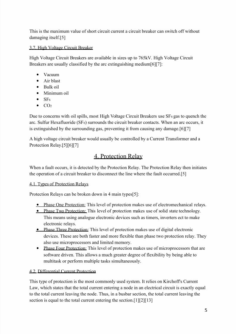
T,is is t,e ma;imum alue of s,ort circuit current a circuit brea(er can sitc, off it,out
dama#in# itself.859
3.-. i#, )olta#e Circuit Brea(er
i#, )olta#e Circuit Brea(ers are aailable in sies u" to -65(). i#, )olta#e CircuitBrea(ers are usuall& classified b& t,e arc e;tin#uis,in# medium8698-9$
• )acuum
• Air blast
• Bul( oil
• Dinimum oil
• S*6
• C%2
/ue to concerns it, oil s"ills7 most i#, )olta#e Circuit Brea(ers use S*6 #as to +uenc, t,earc. Sulfur e;afluoride =S*6> surrounds t,e circuit brea(er contacts. ,en an arc occurs7 it
is e;tin#uis,ed b& t,e surroundin# #as7 "reentin# it from causin# an& dama#e.8698-9
A ,i#, olta#e circuit brea(er ould usuall& be controlled b& a Current Transformer and a
Protection 'ela&.8598698-9
4. Protection 'ela&
,en a fault occurs7 it is detected b& t,e Protection 'ela&. T,e Protection 'ela& t,en initiates
t,e o"eration of a circuit brea(er to disconnect t,e line ,ere t,e fault occurred.859
4.1. T&"es of Protection 'ela&s
Protection 'ela&s can be bro(en don in 4 main t&"es859$
• P,ase %ne Protection$ T,is leel of "rotection ma(es use of electromec,anical rela&s.
• P,ase To Protection$ T,is leel of "rotection ma(es use of solid state tec,nolo#&.
T,is means usin# analo#ue electronic deices suc, as timers7 inerters ect to ma(e
electronic rela&s.
• P,ase T,ree Protection$ T,is leel of "rotection ma(es use of di#ital electronic
deices. T,ese are bot, faster and more fle;ible t,an ",ase to "rotection rela&. T,e&
also use micro"rocessors and limited memor&.
• P,ase *our Protection$ T,is leel of "rotection ma(es use of micro"rocessors t,at are
softare drien. T,is allos a muc, #reater de#ree of fle;ibilit& b& bein# able to
multitas( or "erform multi"le tas(s simultaneousl&.
4.2. /ifferential Current Protection
T,is t&"e of "rotection is t,e most commonl& used s&stem. t relies on Eirc,off:s Current
<a7 ,ic, states t,at t,e total current enterin# a node in an electrical circuit is e;actl& e+ual
to t,e total current leain# t,e node. T,us7 in a busbar section7 t,e total current leain# t,e
section is e+ual to t,e total current enterin# t,e section.8198298139
5

7/17/2019 Protection Ass 2
http://slidepdf.com/reader/full/protection-ass-2 7/12
n t,is s&stem7 Current Transformers=CT> are connected in "arallel to eac, ot,er t,rou#, S1
and S2. T,ese Current Transformers are used to read t,e current floin# t,rou#, t,e lines A7
B7 C7 ect. A Protection 'ela& is also connected in "arallel it, t,e Current Transformers.819
829
nder normal o"eratin# conditions7 a""l&in# Eirc,off:s Current <a around node E ill #ie
us t,e folloin#$
I A+ I B+ I C + I D+ I E+ I F + I R=0
I
I R+(¿¿ A + I B+ I C + I D+ I E+ I F )=0
¿
I R+(∑ of all secondary currents)=¿ 0
I R+0=0
T,erefore I R=0
*i#4.2.1$ A /ifferential Current Protection S&stem it, an ;ternal *ault819
f a fault ere to occur outside of t,e feeders7 li(e in t,e aboe dia#ram7 most of t,e fault
current ould come from t,at feeder. T,e rest of t,e fault current ill be contributed from t,e
ot,er feeders. T,e fault current and contributed fault currents ill flo t,rou#, t,eir
res"ectie Current Transformers. T,is means t,at if e ere to use Eirc,off:s Current <a
around node E7 ' ould still be ero. T,erefore no current ould flo t,rou#, t,e
Protection 'ela&.819829
6

7/17/2019 Protection Ass 2
http://slidepdf.com/reader/full/protection-ass-2 8/12
*i#4.2.2$ A /ifferential Current Protection S&stem it, an nternal *ault819
f a fault ere to occur inside of t,e s&stem7 t,e fault current ould be fed b& all of t,efeeders connected to t,e bus. T,us7 t,e sum of all t,e contributed fault currents ill be e+ual
to t,e fault current itself. /urin# t,is t&"e of fault7 t,ere is no Current Transformer in t,e
fault& "at,s. T,erefore t,e sum of all t,e Current Transformer:s secondar& currents is not
e+ual to ero7 but is e+ual to t,e secondar& e+uialent of t,e fault current. f e no a""l&
Eirc,off:s Current <a e ill see t,at ' is no lon#er ero.819829
/urin# t,is condition7 current ' ill flo t,rou#, t,e Protection 'ela& and cause it to tri"
t,e Circuit Brea(er. ,en t,e Circuit Brea(er tri"s7 it disconnects all t,e feeders connected to
t,is section of t,e busbar. %nce tri""ed7 t,e busbar becomes dead.819829
4.3. Sectionalied Bus
n real orld "ractice7 busbars are se"arated into sections. T,is is done to increase stabilit&. f
a fault ere to occur in one section7 it ould not affect t,e ot,er s&stems. T,is setu" allos a
factor& or "lant to continue it, o"eration ,en a fault occurs on one of t,e busbar s&stems.
819829
*i#4.3$ A Sectionalied Bus it, /ifferential Current Protection819
7
7/17/2019 Protection Ass 2
http://slidepdf.com/reader/full/protection-ass-2 9/12
As &ou can see aboe7 t,is Busbar s&stem is se"arated into to s&stems$ Fone A and Fone B.
Fone A is bound b& CT17 CT2 and CT3. CT1 and CT2 are feeder Current Transformers and
CT3 is a bus Current Transformer. Fone B is bound b& CT57 CT6 and CT4. ,ere CT5 and
CT6 are feeder Current Transformers and CT4 is a bus Current Transformer. Fone A and B
are also oerla""ed to insure no one is left out.819829
T,is s&stem or(s similarl& to t,e /ifferential Current Protection e;ce"t if a fault ere to
occur in Fone A7 onl& t,e corres"ondin# Protection 'ela& ill be tri""ed.819829
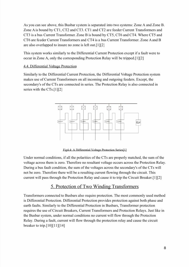
4.4. /ifferential )olta#e Protection
Similarl& to t,e /ifferential Current Protection7 t,e /ifferential )olta#e Protection s&stem
ma(es use of Current Transformers on all incomin# and out#oin# feeders. ;ce"t7 t,e
secondar&:s of t,e CTs are connected in series. T,e Protection 'ela& is also connected in
series it, t,e CTs.819829
*i#4.4$ A /ifferential )olta#e Protection Series819
nder normal conditions7 if all t,e "olarities of t,e CTs are "ro"erl& matc,ed7 t,e sum of t,e
olta#e across t,em is ero. T,erefore no resultant olta#e occurs across t,e Protection 'ela&.
/urin# a bus fault condition7 t,e sum of t,e olta#es across t,e secondar&:s of t,e CTs ill
not be ero. T,erefore t,ere ill be a resultin# current floin# t,rou#, t,e circuit. T,is
current ill "ass t,rou#, t,e Protection 'ela& and cause it to tri" t,e Circuit Brea(er.819829
5. Protection of To indin# Transformers
Transformers connected to Busbars also re+uire "rotection. T,e most commonl& used met,od
is /ifferential Protection. /ifferential Protection "roides "rotection a#ainst bot, ",ase and
eart, faults. Similarl& to t,e /ifferential Protection in Busbars7 Transformer "rotection
re+uires t,e use of Circuit Brea(ers7 Current Transformers and Protection 'ela&s. Just li(e in
t,e Busbar s&stem7 under normal conditions no current ill flo t,rou#, t,e Protection
'ela&. /urin# a fault7 current ill flo t,rou#, t,e "rotection rela& and cause t,e circuit
brea(er to tri".810981198149
8

7/17/2019 Protection Ass 2
http://slidepdf.com/reader/full/protection-ass-2 10/12
5.1. /elta!/elta 3 P,ase Transformer
*i# 5.1. A 3 P,ase delta!delta transformer it, differential current "rotection8119
5.2. Star!Star 3 P,ase Transformer
*i# 5.2. A 3 ",ase star!star transformer it, differential current "rotection8119
5.3. Star!/elta 3 P,ase Transformer
*i# 5.2. A 3 ",ase star!delta transformer it, differential current "rotection8129
9

7/17/2019 Protection Ass 2
http://slidepdf.com/reader/full/protection-ass-2 11/12
)er& similar to t,e Star!Star and /elta!/elta7 e;ce"t for t,e Star!/elta matc,in# transformer
indicated b& t,e blue bloc(.8129
6. Ancillaries
An lectrical Poer Ancillaries7 defined b& t,e nited States *ederal ner#& 'e#ulator&
Commission7 are Gserices necessar& to su""ort t,e transmission of electric "oer from seller
to "urc,aser #ien t,e obli#ations of control areas and transmittin# utilities it,in t,ose
control areas to maintain reliable o"erations of t,e interconnected transmission s&stem.G89
T,ere are 6 (inds of ancillar& serices89$
• 'eactie "oer and olta#e control
• Sc,edulin# and dis"atc,
• <oss com"ensation
• <oad folloin#
• S&stem "rotection
• ner#& imbalance
S&stem "rotection ancillaries include failure "rotection7 adanced #rid reliabilit& anal&sis7
securit& and "rotection serices.89
-. Protection S&stem
sin# t,e information ,ae #at,ered ,ile com"ilin# t,is assi#nment7 s,all e;"lain ,at a
Busbar Protection s&stem ould contain. T,e s&stem com"rises of 2 in feeders at 2-5()7
500D)A and 4 feeders at 132()7 200D)A eac,.
-.1. n *eeder$ ac, in feeder s,ould be "rotected it, a i#, )olta#e Circuit Brea(er rated
at 35() and 600D)A. T,e& s,ould eac, ,ae t,eir on se"arated Circuit Brea(ers so t,at
if one line ere to fault7 t,e ot,er could (ee" "oerin# t,e s&stem at ,alf t,e ca"acit&. T,ese
circuit brea(ers s,ould be installed beteen t,e in feeds and t,e first busbar.
-.2. Transformer$ A transformer ould be connected beteen t,e first and second bus bar.
T,is ould transform t,e "rimar& olta#e of 2-5() to a loer olta#e of 132(). T,e
transformer s,ould ,ae a ratin# of at least 1200D)A. T,e transformer s,ould be "rotected
b& a /ifferential Current Protection s&stem. 3 Circuit Brea(ers ill be installed in its "rimar&
lines7 it, 6 Current Transformers installed in bot, "rimar& and secondar& lines. T,e CTs
ill control a Protection 'ela&7 ,ic, ill tell t,e circuit brea(ers to tri" durin# a fault
condition.
10

7/17/2019 Protection Ass 2
http://slidepdf.com/reader/full/protection-ass-2 12/12
-.3. *eeders$ T,e feeders s,ould be "rotected it, a Sectionalied Bus /ifferential Current
Protection S&stem. 4 indiidual busbars s,ould be used7 it, a circuit brea(er beteen eac,
one. ac, feeder line ill ,ae a circuit brea(er and current transformer installed. A current
transformer s,ould also be installed alon# eac, busbar. T,e circuit brea(ers s,ould be rated at
245()7 250D)A. T,e CT in t,e busbar and in t,e feeder line s,all be ired in "arallel7 alon#it, a "rotection rela&. T,is s,ould be done for eac, feeder. f a fault ere to occur in a
feeder7 t,e "rotectie rela& ill tri" t,e circuit brea(er for t,at feeder7 leain# t,e rest
unaffected. T,is ould allo 3 of t,e 4 feeders to continue runnin# if a fault ere to occur on
one of t,e feeders.Biblio#ra",&
1. ,tt"$@@electrical4u.com@busbar!"rotection@7 /ate Accessed 13!16@04@2015
2. GBus /ifferential ProtectionG7 J.H. Andric,a(7 Jor#e Cardenas7 Journal "resented to
Tent& Second Annual estern Protectie 'ela& Conference7 S"o(ane7 as,in#ton7
%ctober 247 155.
3. ,tt"$@@.electronics!tutorials.s@transformer@current!transformer.,tml7 /ateAccessed 13!16@04@2015
4. ,tt"$@@en.i(i"edia.or#@i(i@CurrentItransformer7 /ate Accessed 13!16@04@2015
5. H.*. d:Almaine7 Glectrical Protection P'T301G7 dition 17 /urban niersit& of
Tec,nolo#&7 /urban7 n"ublis,ed notes for /T students
6. ,tt"$@@en.i(i"edia.or#@i(i@CircuitIbrea(er7 /ate Accessed 13!16@04@2015
-. ,tt"$@@.ener#&.siemens.com@nl@"ool@,+@"oer!transmission@,i#,!olta#e!
"roducts@circuit!brea(er@PortfolioIen."df7 /ate Accessed 13!16@04@2015
. ,tt"$@@en.i(i"edia.or#@i(i@Ancillar&IsericesI2electricI"oer27 /ate
Accessed 13!16@04@2015
. ,tt"$@@.+uora.com@,at!are!electric!#rid!ancillar&!serices7 /ate Accessed 13!16@04@2015
10. ,tt"s$@@.#edi#italener#&.com@smart#rid@Dar0-@article5."df7 /ate Accessed 13!
16@04@2015
11. ,tt"$@@total"oers&stem.blo#s"ot.com@2013@0-@transformers!"rotection.,tml7 /ate
Accessed 13!16@04@2015
12. ,tt"$@@"oer!s&stems!"rotection.blo#s"ot.com@2011@01@"ractical!e;am"le!of!
differential!rela&.,tml7 /ate Accessed 13!16@04@2015
13. ,tt"$@@total"oers&stem.blo#s"ot.com@2013@0-@bus!bars!"rotection.,tml7 /ate
Accessed 13!16@04@2015
14. G/ual Slo"e /ifferential 'ela& As an ffectie Tec,ni+ue for /ifferential Protectionof ! Connected Poer TransformerG7 Ho,il Da&urd,aKsin,7 /r. B,aes, B,alKa7
)ol 1 ssue 3. A"ril 2013
11


![Kick ass 2 [ 01 ]](https://img.dokumen.tips/doc/110x75/568bd7001a28ab20349e23fa/kick-ass-2-01-.jpg)