Embed Size (px)
Citation preview
Lecture 5: Protection and Restoration in Optical Networks 1/
Optical Communication Systems and Networks
Lecture 5: Protection and Restoration in Optical Networks 1/
Optical Communication Systems and Networks
8. Protection and restoration in optical networks
Optical Communication Systems and Networks

Lecture 5: Protection and Restoration in Optical Networks 2/
Optical Communication Systems and Networks
Lecture 8: Protection and Restoration in Optical Networks 2/
Optical Communication Systems and Networks
Optical Networks. A practical perspective Rajiv Ramaswami, Kumar N. Sivarajan, Chapter 10, pp. 537-594, Ed. Morgan-kaufmann. 2nd Edition, 2002.
Redes Ópticas José Capmany, Beatriz Ortega, Chapter 7, Ed. Servicio de Publicaciones Universidad Politécnica de Valencia, 2006.
BIBLIOGRAPHY
31
Lecture 5: Protection and Restoration in Optical Networks 3/
Optical Communication Systems and Networks
Lecture 8: Protection and Restoration in Optical Networks 3/
Optical Communication Systems and Networks
Objetives:
– To provide a resilient network against failures. It becomes an essential requeriment during the design of high speed optical networks
– To offer a reliable service when large volume of traffic is transmited even in the presence of failures and anomalous operation. A large amount of data can be lost unless restoration mechanisms are set quickly
Frequently faults:
– Fiber cuts (human errors)
– Failure of active components (transmitters, receivers, amplifiers, controllers)
– Disruption of service (software)
– Catastrophic events (flooding, fire)
– Aging of components
Protection mechanisms operate in the optical domain, and they profit from inherent transparency and scalability in order to provide high capacity networks
Incorporate functions such as monitoring, fault detection and ability to activate protection and restoration (mainly performed in optical switches)
Introduction to Network Survivability
31
Lecture 5: Protection and Restoration in Optical Networks 4/
Optical Communication Systems and Networks
Lecture 8: Protection and Restoration in Optical Networks 4/
Optical Communication Systems and Networks
The optical layer can handle some faults more efficiently than the client layers. Optical layer protection can provide an additional degree of resilience in the network to protect against multiple failures
Advantages:
– Optical layer is taken in advantage to provide protection resources among users, independently of their origin and format
– Protection and restoration functions are supplied to electronic networks which lack them (PDH, ESCON ...)
– It is used simpler techniques implying a reduced number of network entities
– They do not need electronic coordination from higher layers
Limitations:
– Optical protection can not solve failures in higher layer equipment, For example: It is not able to detect high BER.
– The optical switches are not as safe as electronics due to their young age
– Difficulty in coordination between the various entities involved in the processes of optical protection and higher levels
– Proposed restoration routes (depending on the scheme) may assist the development of degrading phenomena
Tem
a 7
: Té
cnic
as d
e P
rote
cció
n
Introduction to Network Survivability
31
Lecture 5: Protection and Restoration in Optical Networks 5/
Optical Communication Systems and Networks
Lecture 8: Protection and Restoration in Optical Networks 5/
Optical Communication Systems and Networks
Restoration must be performed in the shortest time possible: the longer is out of service, the greater volume of information is lost
The maximum time to perform traffic restoration is 60 ms (imposed by SONET/SDH) to avoid the loss of frame synchronization
– This time includes: time of fault detection and location, time of signal propagation, delay and switching times
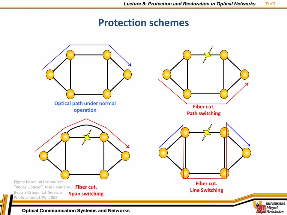
Working paths: optical paths established for carrying traffic under normal operation (SDH, ATM, IP…)
Protection paths: optical paths are established to provide alternative routes and to reroute the work traffic when failures occur. Then protection can be performed by:
– Path switching
• It occurs between source and destination: traffic is rerouted end to end along an alternative path.
– Line switching
• It takes place between the two nodes that define where the failure has occurred.
• It may be also performed by span-basis protection (an alternative route between both nodes) or by protection line
Tem
a 7
: Té
cnic
as d
e P
rote
cció
n
Protection concepts
31
Lecture 5: Protection and Restoration in Optical Networks 6/
Optical Communication Systems and Networks
Lecture 8: Protection and Restoration in Optical Networks 6/
Optical Communication Systems and Networks
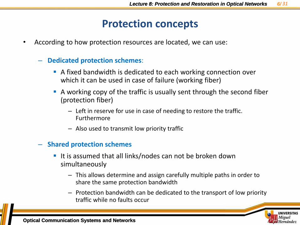
• According to how protection resources are located, we can use:
– Dedicated protection schemes:
A fixed bandwidth is dedicated to each working connection over which it can be used in case of failure (working fiber)
A working copy of the traffic is usually sent through the second fiber (protection fiber)
– Left in reserve for use in case of needing to restore the traffic. Furthermore
– Also used to transmit low priority traffic
– Shared protection schemes
It is assumed that all links/nodes can not be broken down simultaneously
– This allows determine and assign carefully multiple paths in order to share the same protection bandwidth
– Protection bandwidth can be dedicated to the transport of low priority traffic while no faults occur
Tem
a 7
: Té
cnic
as d
e P
rote
cció
n
Protection concepts
31
Lecture 5: Protection and Restoration in Optical Networks 7/
Optical Communication Systems and Networks
Lecture 8: Protection and Restoration in Optical Networks 7/
Optical Communication Systems and Networks
Optical path under normal operation
Fiber cut. Path switching
Fiber cut. Span switching
Fiber cut. Line Switching
Protection schemes
31
Figure based on the source: “Redes Ópticas”, José Capmany, Beatriz Ortega, Ed. Servicio Publicaciones UPV, 2006
Lecture 5: Protection and Restoration in Optical Networks 8/
Optical Communication Systems and Networks
Lecture 8: Protection and Restoration in Optical Networks 8/
Optical Communication Systems and Networks
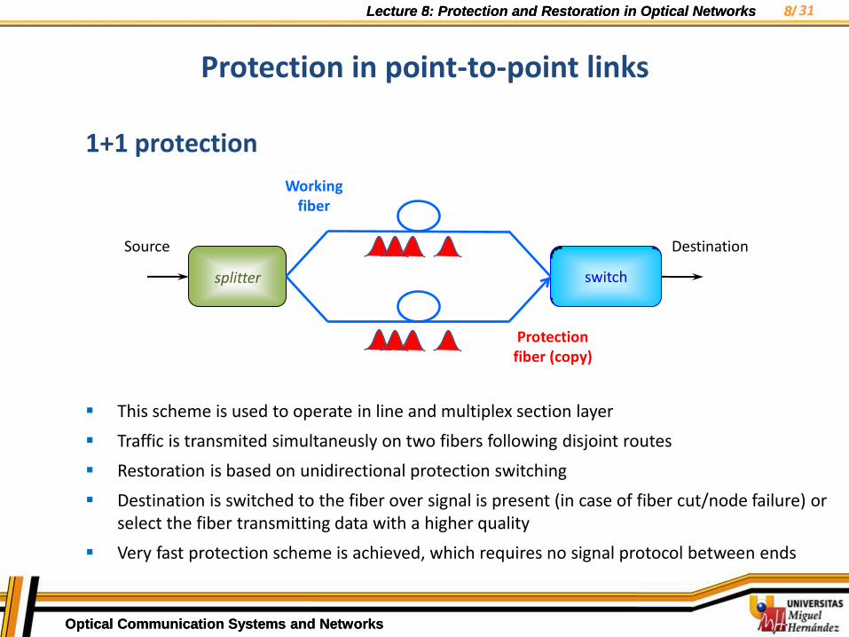
Protection in point-to-point links
1+1 protection
This scheme is used to operate in line and multiplex section layer
Traffic is transmited simultaneusly on two fibers following disjoint routes
Restoration is based on unidirectional protection switching
Destination is switched to the fiber over signal is present (in case of fiber cut/node failure) or select the fiber transmitting data with a higher quality
Very fast protection scheme is achieved, which requires no signal protocol between ends
splitter
switch
Source Destination
Working fiber
Protection fiber (copy)
31

Lecture 5: Protection and Restoration in Optical Networks 9/
Optical Communication Systems and Networks
Lecture 8: Protection and Restoration in Optical Networks 9/
Optical Communication Systems and Networks
Protection in point-to-point links
1:1 protection
This scheme is also used to operate in line and multiplex section layer
Unlike 1+1 protection, traffic is transmitted only on one fiber at a time (working fiber), while the second fiber remains waiting for a failure (protection fiber)
Meanwhile, the secon fiber can be used for transmitting low priority traffic
Traffic restoration requires the use of a signaling protocol APS (automatic protocol-switching) to coordinate the retransmission between transmitter and receiver
switch
switch
Source Destination
Working fiber
Protection fiber
31

Lecture 5: Protection and Restoration in Optical Networks 10/
Optical Communication Systems and Networks
Lecture 8: Protection and Restoration in Optical Networks 10/
Optical Communication Systems and Networks
Protection in point-to-point links
1:N protection
switch
switch Source 1
Destination 1
Protection fiber
Working fiber
switch
switch Source 2
conmutador
switch
Source N
switch
switch
Low priority traffic
Destination 2
Destination N
31
Lecture 5: Protection and Restoration in Optical Networks 11/
Optical Communication Systems and Networks
Lecture 8: Protection and Restoration in Optical Networks 11/
Optical Communication Systems and Networks
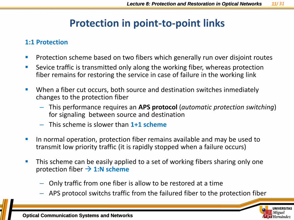
1:1 Protection
Protection scheme based on two fibers which generally run over disjoint routes
Sevice traffic is transmitted only along the working fiber, whereas protection fiber remains for restoring the service in case of failure in the working link
When a fiber cut occurs, both source and destination switches inmediately changes to the protection fiber
– This performance requires an APS protocol (automatic protection switching) for signaling between source and destination
– This scheme is slower than 1+1 scheme
In normal operation, protection fiber remains available and may be used to transmit low priority traffic (it is rapidly stopped when a failure occurs)
This scheme can be easily applied to a set of working fibers sharing only one protection fiber 1:N scheme
– Only traffic from one fiber is allow to be restored at a time
– APS protocol switchs traffic from the failured fiber to the protection fiber
Tem
a 7
: Té
cnic
as d
e P
rote
cció
n
Protection in point-to-point links
31

Lecture 5: Protection and Restoration in Optical Networks 12/
Optical Communication Systems and Networks
Lecture 8: Protection and Restoration in Optical Networks 12/
Optical Communication Systems and Networks
Protection in ring-based networks
• Ring topologies are best suited for its safety and durability to provide reliable services in case of node failures or fiber cuts
Allows the traffic routing away from the failure preventing information loss.
Compared to mesh networks, rings are capable of providing a simpler, more rapid restoration traffic and with lower requirements in the network management system.
SDH ring denominated SHR (Self Healing Ring) detect and reroute traffic far away from the affected node or fiber to the correspondent protection fiber or bandwidth
• Different types of ring architectures depend on:
1) Directionality of traffic:
– Unidirectional ring: carries working trafric in only one direction of the ring
– Bidirectional ring: carries working trafric in both direction
2) Protection switching: according to the ITU-T G.872 recommendation:
– fiber-line: fiber link connecting two adjacent nodes
– wavelength-path: Optical connection supported by a wavelength between source and destination nodes
Tem
a 7
: Té
cnic
as d
e P
rote
cció
n 31
Lecture 5: Protection and Restoration in Optical Networks 13/
Optical Communication Systems and Networks
Lecture 8: Protection and Restoration in Optical Networks 13/
Optical Communication Systems and Networks
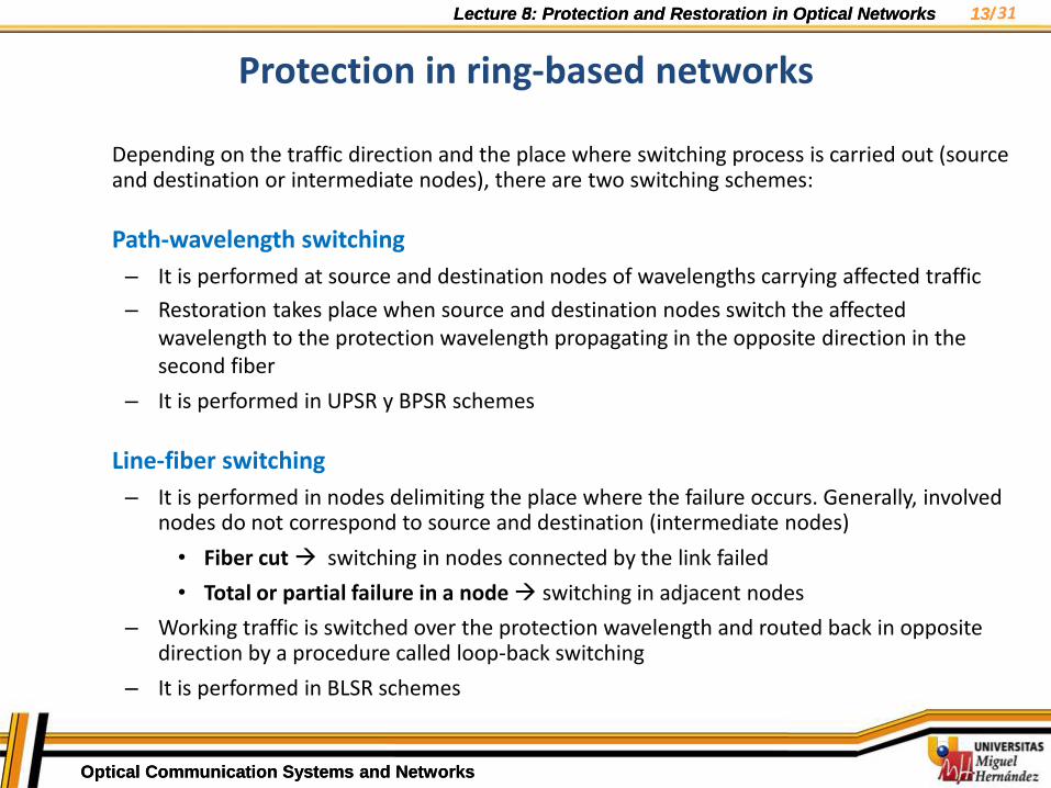
Depending on the traffic direction and the place where switching process is carried out (source and destination or intermediate nodes), there are two switching schemes:
Path-wavelength switching
– It is performed at source and destination nodes of wavelengths carrying affected traffic
– Restoration takes place when source and destination nodes switch the affected wavelength to the protection wavelength propagating in the opposite direction in the second fiber
– It is performed in UPSR y BPSR schemes
Line-fiber switching
– It is performed in nodes delimiting the place where the failure occurs. Generally, involved nodes do not correspond to source and destination (intermediate nodes)
• Fiber cut switching in nodes connected by the link failed
• Total or partial failure in a node switching in adjacent nodes
– Working traffic is switched over the protection wavelength and routed back in opposite direction by a procedure called loop-back switching
– It is performed in BLSR schemes
Tem
a 7
: Té
cnic
as d
e P
rote
cció
n
Protection in ring-based networks
31
Lecture 5: Protection and Restoration in Optical Networks 14/
Optical Communication Systems and Networks
Lecture 8: Protection and Restoration in Optical Networks 14/
Optical Communication Systems and Networks
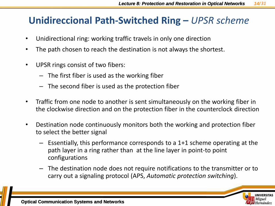
Unidireccional Path-Switched Ring – UPSR scheme
• Unidirectional ring: working traffic travels in only one direction
• The path chosen to reach the destination is not always the shortest.
• UPSR rings consist of two fibers:
– The first fiber is used as the working fiber
– The second fiber is used as the protection fiber
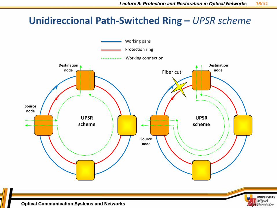
• Traffic from one node to another is sent simultaneously on the working fiber in the clockwise direction and on the protection fiber in the counterclock direction
• Destination node continuously monitors both the working and protection fiber to select the better signal
– Essentially, this performance corresponds to a 1+1 scheme operating at the path layer in a ring rather than at the line layer in point-to point configurations
– The destination node does not require notifications to the transmitter or to carry out a signaling protocol (APS, Automatic protection switching).
Tem
a 7
: Té
cnic
as d
e P
rote
cció
n 31
Lecture 5: Protection and Restoration in Optical Networks 15/
Optical Communication Systems and Networks
Lecture 8: Protection and Restoration in Optical Networks 15/
Optical Communication Systems and Networks
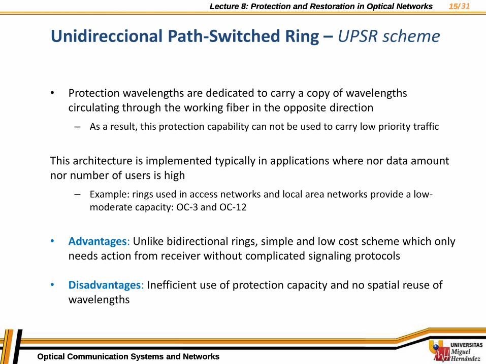
• Protection wavelengths are dedicated to carry a copy of wavelengths circulating through the working fiber in the opposite direction
– As a result, this protection capability can not be used to carry low priority traffic
This architecture is implemented typically in applications where nor data amount nor number of users is high
– Example: rings used in access networks and local area networks provide a low-moderate capacity: OC-3 and OC-12
• Advantages: Unlike bidirectional rings, simple and low cost scheme which only needs action from receiver without complicated signaling protocols
• Disadvantages: Inefficient use of protection capacity and no spatial reuse of wavelengths
Tem
a 7
: Té
cnic
as d
e P
rote
cció
n
Unidireccional Path-Switched Ring – UPSR scheme
31
Lecture 5: Protection and Restoration in Optical Networks 16/
Optical Communication Systems and Networks
Lecture 8: Protection and Restoration in Optical Networks 16/
Optical Communication Systems and Networks
Source node
Destination
node
UPSR scheme
UPSR scheme
Working pahs
Protection ring
Working connection
Fiber cut
Source node
Destination
node
Unidireccional Path-Switched Ring – UPSR scheme
31

Lecture 5: Protection and Restoration in Optical Networks 17/
Optical Communication Systems and Networks
Lecture 8: Protection and Restoration in Optical Networks 17/
Optical Communication Systems and Networks
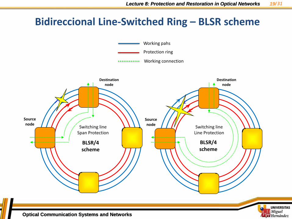
• BLSR can be implemented by 2 or 4 fiber rings, depending on the required capacity, providing: BLSR/2 or BLSR/4 (50% traffic bandwidth and 50% protection bandwidth).
• BLSR is a bidirectional ring over which working traffic is sent in both directions:
– Optical connections reach destination following the shortest path
• Both schemes (2 and 4-fiber rings) present mechanisms of line protection switching, since span protection is not implemented usually in this architecture
• Service traffic is transferred to the corresponding protection wavelength placed on the other fiber (called Loop-back process switching, LBS)
– This wavelength carries the traffic along the ring in opposite direction until reaching the second node, where the wavelength is switched again (LBS) to set the protected traffic on the working wavelength initially assigned
– This wavelength propagates along the first fiber according to the initial direction until reaching the destination node
Tem
a 7
: Té
cnic
as d
e P
rote
cció
n
Bidireccional Line-Switched Ring - BLSR scheme
31

Lecture 5: Protection and Restoration in Optical Networks 18/
Optical Communication Systems and Networks
Lecture 8: Protection and Restoration in Optical Networks 18/
Optical Communication Systems and Networks
Bidireccional Line-Switched Ring - BLSR scheme
Unlike UPSR:
– BLSR requires an APS protocol to perform line switching between nodes delimiting the affected place (cut or node failure)
– Performance and features of involved elements in protection are more complex
– Line switching makes operation wavelengths run over longer distances with regard to the normal operation mode. There are several consequences:
Impairments due to nonlienearities can be increased
Restoration process slower than UPSR and BPSR schemes
Advantages vs UPSR:
• Working wavelegths can circulate in both directinos:
– Working wavelengths follow the shorter route to reach the destination node
– Spatial reuse of wavelengths is allowed
• BLSR are based on shared protection schemes:
– Under normal operation mode, protection wavelengths carry low priority traffic
• When a failure occurs, the low priority traffic will be emptied and wording traffic will be transferred to protection wavelengths by protection mechanisms
Tem
a 7
: Té
cnic
as d
e P
rote
cció
n 31
Lecture 5: Protection and Restoration in Optical Networks 19/
Optical Communication Systems and Networks
Lecture 8: Protection and Restoration in Optical Networks 19/
Optical Communication Systems and Networks
Bidireccional Line-Switched Ring – BLSR scheme Te
ma
7:
Técn
icas
de
Pro
tecc
ión
Working pahs
Protection ring
Working connection
Switching line Span Protection
Switching line Line Protection
BLSR/4 scheme
BLSR/4 scheme
Source node
Destination node
Source node
Destination node
31
Lecture 5: Protection and Restoration in Optical Networks 20/
Optical Communication Systems and Networks
Lecture 8: Protection and Restoration in Optical Networks 20/
Optical Communication Systems and Networks
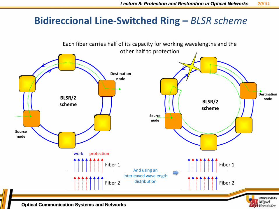
Bidireccional Line-Switched Ring – BLSR scheme
Each fiber carries half of its capacity for working wavelengths and the other half to protection
Fiber 1
Fiber 2
work protection
BLSR/2 scheme
Source node
Destination node
Source node
Destination node
And using an interleaved wavelength
distribution
BLSR/2 scheme
Fiber 1
Fiber 2
31
Lecture 5: Protection and Restoration in Optical Networks 21/
Optical Communication Systems and Networks
Lecture 8: Protection and Restoration in Optical Networks 21/
Optical Communication Systems and Networks
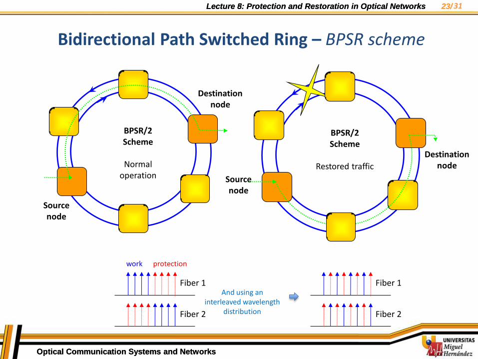
Bidirectional Path Switched Ring – BPSR scheme
• BPSR is a combination of the previous schemes studied
• Bidirectional ring consisting of 2 or 4 fibers, where each fiber dedicates half of its capacity for protection and the other half to working traffic
• As in the BLSR scheme, BPSR achieves the same efficiency in wavelegth use (higher than UPSR): Wavelengths reach their destination following the shortest path
Allows spatial reuse of wavelengths
All working lengths share the same protection capability
The protection wavelengths are permanently ready to restore the working wavelength traffic
• They can be used to carry low priority traffic while their use is not required
• As in UPSR scheme, BPSR implements path-wavelength switching performs protection switching is performed in the source and destination nodes
Tem
a 7
: Té
cnic
as d
e P
rote
cció
n 31
Lecture 5: Protection and Restoration in Optical Networks 22/
Optical Communication Systems and Networks
Lecture 8: Protection and Restoration in Optical Networks 22/
Optical Communication Systems and Networks
• Optical paths dedicated to protection will not be formed until failure occurs meanwhile protection capacity is shared
• When a failure occurs, the destination node will realize the absence of signal. Then, a protocol APS run by the destination will notify the source of the need to start jointly the protection switching process
• Working traffic initially transmitted along one of the fibers in clockwise direction is switched in the source node to the protection wavelength. This wavelength propagates in counterclockwise direction along the second fiber, using the unaffected part of the ring.
• At the same time, destination node will switch to this wavelength in order to receive the service traffic
• Generally, this length is generally much shorter than the distance employed in BLSR protection schemes (the same in UPSR scheme), then:
Restoration time is faster than BLSR schemes
As a result of a shorter length, it is more difficult to reach thresholds providing degrading (dispersion or attenuation) and nonlinear effects
Tem
a 7
: Té
cnic
as d
e P
rote
cció
n
Bidirectional Path Switched Ring – BPSR scheme
31
Lecture 5: Protection and Restoration in Optical Networks 23/
Optical Communication Systems and Networks
Lecture 8: Protection and Restoration in Optical Networks 23/
Optical Communication Systems and Networks
BPSR/2 Scheme
Normal
operation
Source node
Destination node
BPSR/2 Scheme
Restored traffic
Source node
Destination node
Tem
a 7
: Té
cnic
as d
e P
rote
cció
n
Bidirectional Path Switched Ring – BPSR scheme
Fiber 1
Fiber 2
work protection
And using an interleaved wavelength
distribution
Fiber 1
Fiber 2
31
Lecture 5: Protection and Restoration in Optical Networks 24/
Optical Communication Systems and Networks
Lecture 8: Protection and Restoration in Optical Networks 24/
Optical Communication Systems and Networks
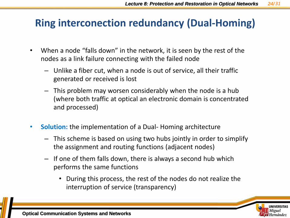
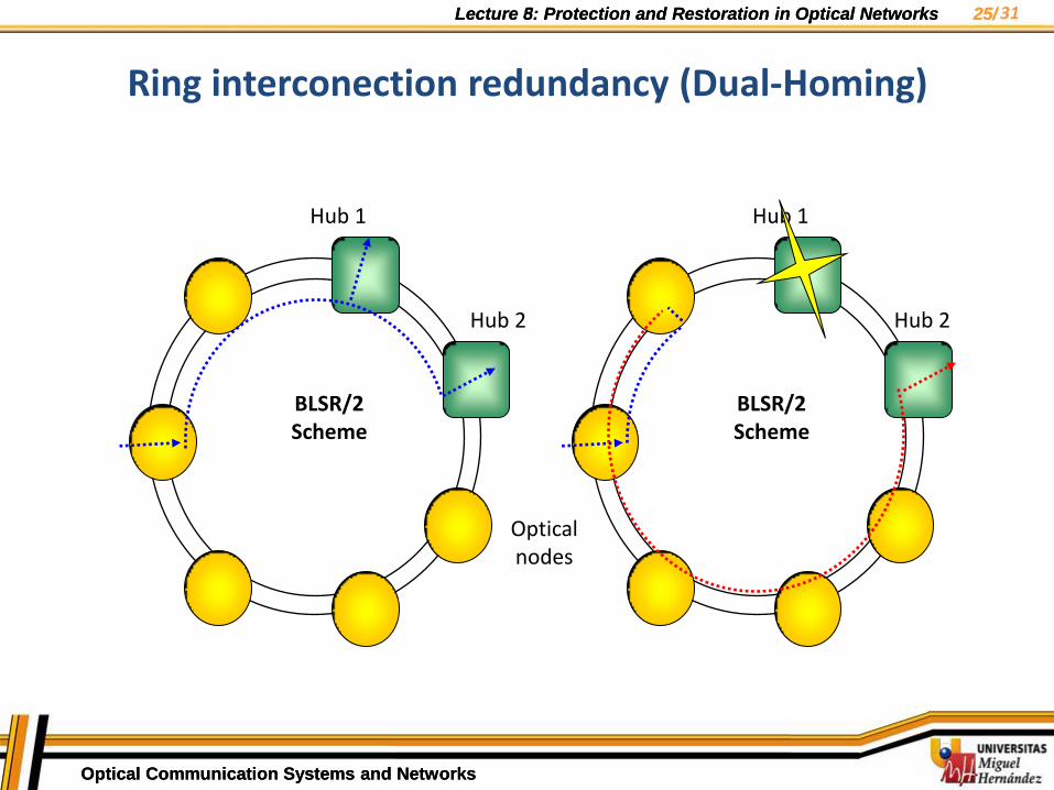
Ring interconection redundancy (Dual-Homing)
• When a node “falls down” in the network, it is seen by the rest of the nodes as a link failure connecting with the failed node
– Unlike a fiber cut, when a node is out of service, all their traffic generated or received is lost
– This problem may worsen considerably when the node is a hub (where both traffic at optical an electronic domain is concentrated and processed)
• Solution: the implementation of a Dual- Homing architecture
– This scheme is based on using two hubs jointly in order to simplify the assignment and routing functions (adjacent nodes)
– If one of them falls down, there is always a second hub which performs the same functions
• During this process, the rest of the nodes do not realize the interruption of service (transparency)
31
Lecture 5: Protection and Restoration in Optical Networks 25/
Optical Communication Systems and Networks
Lecture 8: Protection and Restoration in Optical Networks 25/
Optical Communication Systems and Networks
Optical nodes
Hub 1
Hub 2
Hub 1
Hub 2
BLSR/2 Scheme
BLSR/2 Scheme
Ring interconection redundancy (Dual-Homing)
31

Lecture 5: Protection and Restoration in Optical Networks 26/
Optical Communication Systems and Networks
Lecture 8: Protection and Restoration in Optical Networks 26/
Optical Communication Systems and Networks
Application of protection schemes in meshed topologies is more complex than point-to-point and ring topologies
As the number of nodes and links grows, a greater number of alternative routes can be established to restore traffic in case of failure
To apply protection and restoration mechanisms a division into small domains is made from the mesh
Each domain is able to be implemented protection schemes addressed previously
– Optical network supports the generation of simultaneous failures in different domains
– In domains with a small size a higher security level is achived at expense of inefficient use of network resources
Problems:
– Coordination of protection activation becomes a difficult task
– Alternative routing paths must satisfy time and power budgets as well as recovery within 50 ms time interval to avoid loosing sync of SDH/SONET
Tem
a 7
: Té
cnic
as d
e P
rote
cció
n
Protection in meshed networks
31

Lecture 5: Protection and Restoration in Optical Networks 27/
Optical Communication Systems and Networks
Lecture 8: Protection and Restoration in Optical Networks 27/
Optical Communication Systems and Networks
Tem
a 7
: Té
cnic
as d
e P
rote
cció
n
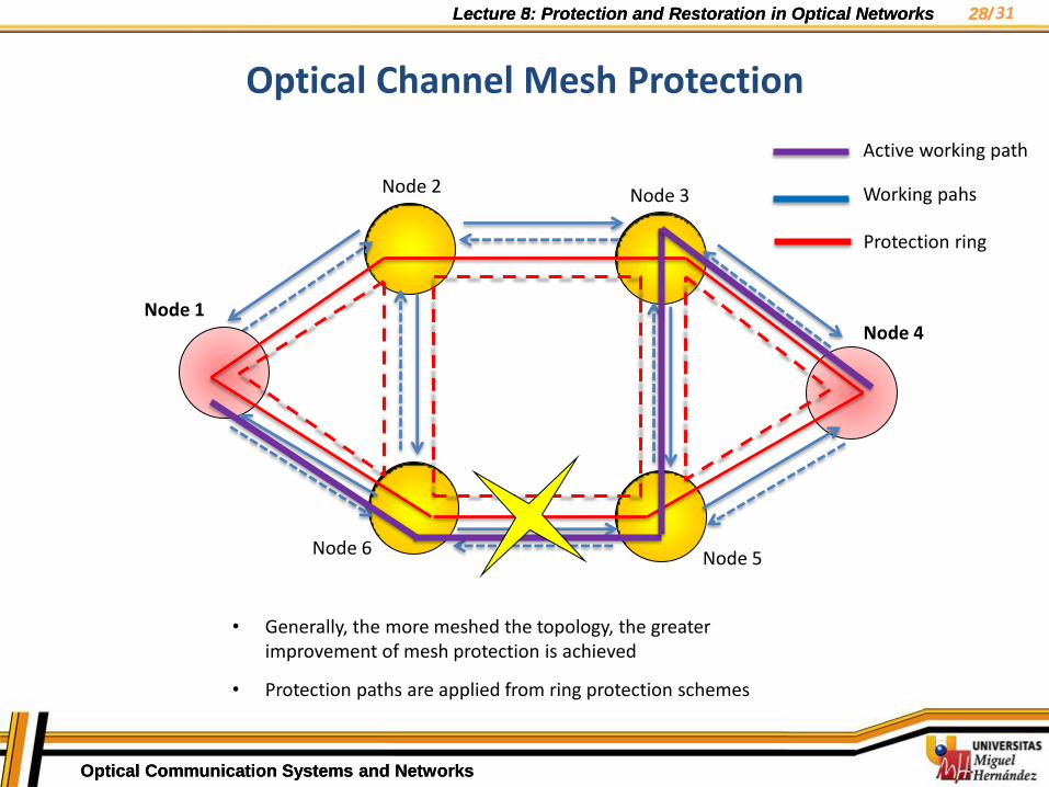
• Generally, the more meshed the topology, the greater improvement of mesh protection is achieved
• Protection paths are applied from ring protection schemes
Node 1
Node 2 Node 3
Node 4
Node 5 Node 6
Optical Channel Mesh Protection
31
Figure based on the source: “Redes Ópticas”, José Capmany, Beatriz Ortega, Ed. Servicio Publicaciones UPV, 2006
Lecture 5: Protection and Restoration in Optical Networks 28/
Optical Communication Systems and Networks
Lecture 8: Protection and Restoration in Optical Networks 28/
Optical Communication Systems and Networks
Tem
a 7
: Té
cnic
as d
e P
rote
cció
n
Node 1
Node 2 Node 3
Node 4
Node 5 Node 6
• Generally, the more meshed the topology, the greater improvement of mesh protection is achieved
• Protection paths are applied from ring protection schemes
Active working path
Working pahs
Protection ring
Optical Channel Mesh Protection
31
Lecture 5: Protection and Restoration in Optical Networks 29/
Optical Communication Systems and Networks
Lecture 8: Protection and Restoration in Optical Networks 29/
Optical Communication Systems and Networks
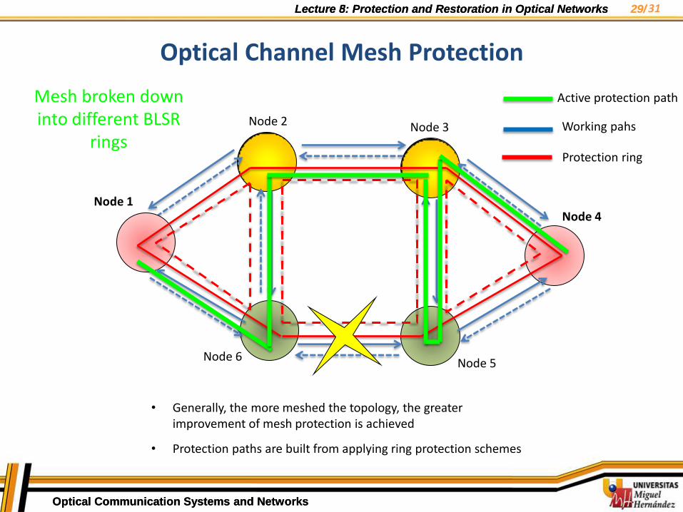
Optical Channel Mesh Protection Te
ma
7:
Técn
icas
de
Pro
tecc
ión
Node 1
Node 2 Node 3
Node 4
Node 5 Node 6
Mesh broken down into different BLSR
rings
• Generally, the more meshed the topology, the greater improvement of mesh protection is achieved
• Protection paths are built from applying ring protection schemes
Active protection path
Working pahs
Protection ring
31

Lecture 5: Protection and Restoration in Optical Networks 30/
Optical Communication Systems and Networks
Lecture 8: Protection and Restoration in Optical Networks 30/
Optical Communication Systems and Networks
Optical Channel Mesh Protection Te
ma
7:
Técn
icas
de
Pro
tecc
ión
Node 1
Node 2 Node 3
Node 4
Node 5 Node 6
Mesh broken down into different BPSR
rings
• Generally, the more meshed the topology, the greater improvement of mesh protection is achieved
• Protection paths are built from applying ring protection schemes
Active protection path
Working pahs
Protection ring
31

Lecture 5: Protection and Restoration in Optical Networks 31/
Optical Communication Systems and Networks
Lecture 8: Protection and Restoration in Optical Networks 31/
Optical Communication Systems and Networks
• A layered network usually presents protection mechanisms in each layer
• The layered solution presents advantages in terms of cost savings and reduction of equipment
• There are some points to consider:
As each layer works independiently, a failure could simultenously trigger different protection actions in the same network
This could lead to generate an innecesary number of alarm signals which could collapse the management center.
• For this reason is necessary to determinate coordination mechanisms among different layers and determine limits in the recovery time for each layer
Tem
a 7
: Té
cnic
as d
e P
rote
cció
n
Operation between layers
31