Embed Size (px)
Citation preview

Protecting Distribution Feeders for Simultaneous Faults
Jorge Betanzos Manuel and Héctor E. Lemus Zavala Comisión Federal de Electricidad
Eliseo Alcázar Ramírez, David Sánchez Escobedo, and Héctor J. Altuve Schweitzer Engineering Laboratories, Inc.
Presented at the 37th Annual Western Protective Relay Conference
Spokane, Washington October 19–21, 2010
Originally presented at the 63rd Annual Conference for Protective Relay Engineers, March 2010

1
Protecting Distribution Feeders for Simultaneous Faults
Jorge Betanzos Manuel and Héctor E. Lemus Zavala, Comisión Federal de Electricidad, Mexico Eliseo Alcázar Ramírez, David Sánchez Escobedo, and Héctor J. Altuve, Schweitzer Engineering Laboratories, Inc.
Abstract—Overhead distribution systems may experience faults involving more than one feeder. During simultaneous faults, the transformer low-voltage-side overcurrent relay measures a current greater than the current measured by faulted feeder relays. Therefore, the transformer relay may trip faster than faulted feeder relays. Transformer relay misoperation affects service availability in circuits not involved with the fault.
In this paper, we describe the causes of simultaneous faults on distribution feeders and discuss overcurrent protection coordination problems caused by these faults. We then propose low-cost protection schemes using multifunction relays with communications and logic programming abilities. We summarize the operation experience of 19 simultaneous fault protection schemes installed in several substations of two Comisión Federal de Electricidad (CFE) distribution divisions in Mexico. Finally, we analyze the operation of a protection scheme for an actual simultaneous fault.
I. INTRODUCTION In radial distribution substations, feeder relays typically
include instantaneous and inverse-time overcurrent elements. The transformer low-voltage-side relay provides backup for feeder faults and typically includes inverse-time overcurrent elements. Utilities normally use automatic reclosing of overhead feeder breakers. The transformer low-voltage-side breaker lacks automatic reclosing.
For feeder faults, the faulted feeder relay and transformer relay measure practically the same current. The feeder relays are set to operate faster than the transformer low-voltage-side relay to trip only the faulted feeder. However, for simultaneous feeder faults, the current measured by the transformer relay is greater than the current measured by each faulted feeder relay. The transformer relay may operate faster than the faulted feeder relay and undesirably trip the transformer low-voltage-side breaker. Transformer breaker misoperation affects service to the loads of healthy feeders.
Given the growing incidence of simultaneous faults, Comisión Federal de Electricidad (CFE), the Mexican national electric utility, decided to apply simultaneous fault protection schemes in distribution substations several years ago. For example, the CFE Southeastern Distribution Division has 18 schemes in operation, and the CFE Jalisco Distribution Division recently commissioned one scheme.
In this paper, we discuss the overcurrent protection coordination problems caused by simultaneous faults. We describe two types of simultaneous fault protection schemes for distribution substations and summarize the operation experience of the schemes installed in several substations of the CFE distribution divisions mentioned above. Finally, we
analyze the operation of a protection scheme for an actual fault involving two feeders of the Oaxaca Uno Substation located in Oaxaca de Juárez, Oaxaca, Mexico.
II. SIMULTANEOUS FAULTS The need to improve service availability has increased the
complexity of distribution network topology. Disconnect switches allow transferring loads to alternate sources under emergency conditions. Limitations on the rights of way make it necessary to use multicircuit overhead lines or single-circuit lines that run close to each other. As a result, simultaneous faults involving more than one circuit are becoming quite common. Typical causes of simultaneous faults include:
• Multicircuit lines or lines sharing the same right of way
• Switching operations • Thunderstorms
Fig. 1 shows a distribution system with four feeders and normally open (NO) disconnect switches between adjacent feeders.
BT
B1
B2
B3
B4
S1 (NC)
S2 (NC)
S3 (NC)
S4 (NC)
T
T
T
T
TT
T
S34 (NO)
S23 (NO)
S12 (NO)
Feeder 1
Feeder 2
Feeder 3
Feeder 4
Fig. 1. Operation of tie disconnect switches may cause simultaneous faults in distribution systems.
Under normal conditions, the system shown in Fig. 1 operates radially. For a permanent fault on Feeder 2 between Breaker B2 and the normally closed (NC) Disconnect Switch S2, Breaker B2 trips and recloses to lockout. Operation personnel open Disconnect Switch S2 to isolate the fault and then close either Disconnect Switch S12 or Disconnect Switch S23 to restore service to the Feeder 2 load connected beyond Disconnect Switch S2. When remote access to motor-operated disconnect (MOD) switches is available, the system operator can send control commands to MOD switches from the distribution system dispatch center, in which case, service

2
restoration may take minutes. When remote access is not available, the system operator dispatches field personnel to manually perform the switching operations, in which case, service restoration may take hours.
Because switching operations are infrequent events, it is necessary to periodically close and open the NO disconnect switches as a preventive maintenance operation. This operation may cause a simultaneous fault in two ways:
• The disconnect switch fails during the test. • A feeder fault occurs while the disconnect switch is
closed.
III. RELAY COORDINATION PROBLEMS For a feeder fault in a radial distribution system, the
transformer low-voltage-side overcurrent relay and the faulted feeder overcurrent relay measure practically the same current (see Fig. 2).
Fig. 2. For a feeder fault, the transformer relay and faulted feeder relay measure practically the same current.
Fig. 3 shows an example of coordination between the inverse-time overcurrent elements of the transformer and feeder relays. For feeder faults, the inverse-time overcurrent elements must coordinate for all possible fault current values. The typical coordination time interval (CTI) is 0.2 to 0.4 seconds. When both elements have the same type of time-current curve, the minimum separation between the curves occurs for the maximum fault current value. In the coordination example shown in Fig. 3, the curve separation equals a CTI of 0.3 seconds for a maximum fault current of 6,750 A. The transformer relay overcurrent element must also protect the transformer against through faults. Hence, the time-current curve of the transformer relay overcurrent element must be located between the feeder relay overcurrent element curve and the transformer through-fault capability curve, as shown in Fig. 3. The transformer relay actually measures the sum of all feeder currents, including load. If load is high enough, the transformer relay settings (pickup or time dial) must be increased. The examples shown in Fig. 3, Fig. 5, and Fig. 6 assume light load conditions.
For a simultaneous fault involving two or more feeders (see Fig. 4), the transformer low-voltage-side relay measures the total fault current (sum of the currents on all faulted feeders)
plus load currents from unfaulted feeders. The relay of each faulted feeder measures only the feeder fault current. Hence, the transformer relay inverse-time overcurrent element may trip faster than or simultaneously with the feeder relay inverse-time overcurrent element. Transformer relay misoperation for simultaneous feeder faults disconnects the faulted and healthy feeders. All of the loads fed by the transformer lose service for permanent or temporary faults, because the transformer low-voltage-side breaker lacks automatic reclosing. Operation personnel must travel to the substation to manually reclose the transformer breaker, in which case, service restoration may take hours, even for a temporary fault.
Fig. 3. Coordination of inverse-time overcurrent elements for feeder faults.
Fig. 4. For a simultaneous fault, the transformer relay measures a current greater than the current measured by each faulted feeder relay.
3
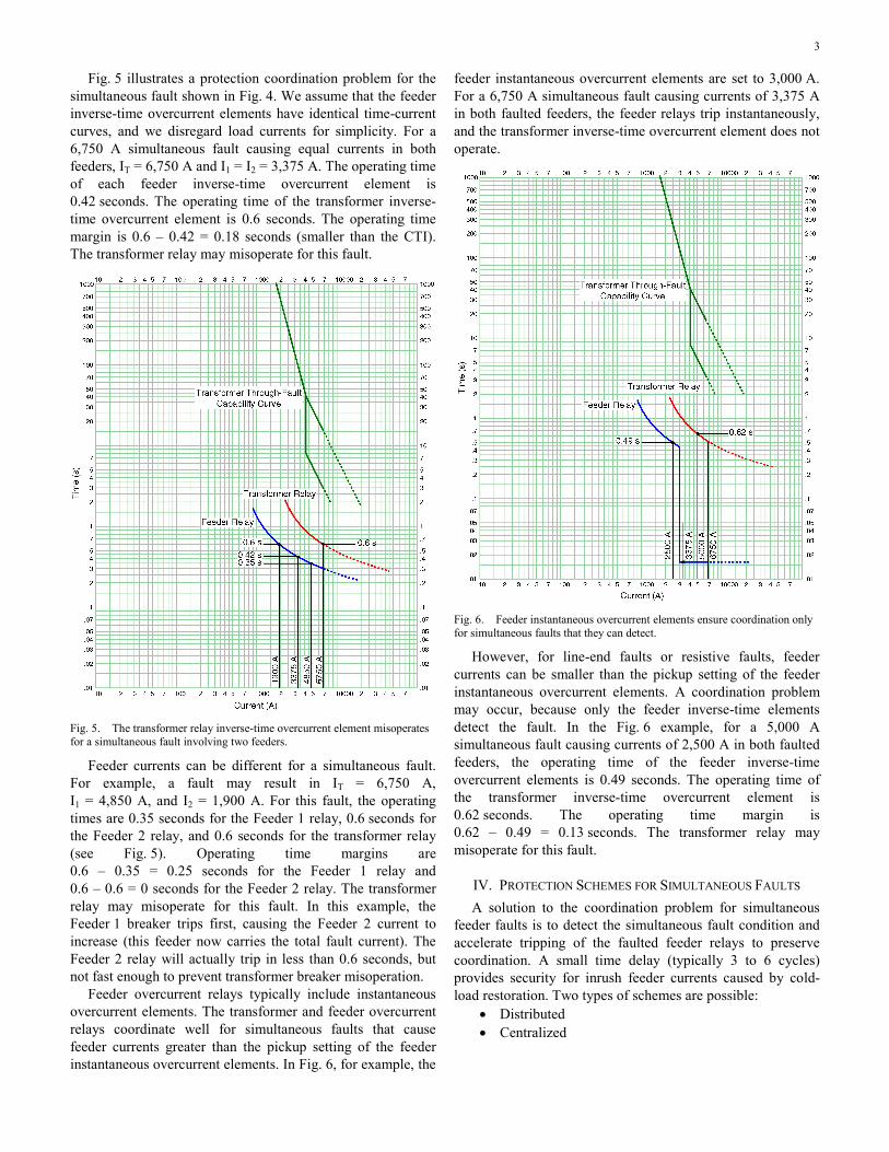
Fig. 5 illustrates a protection coordination problem for the simultaneous fault shown in Fig. 4. We assume that the feeder inverse-time overcurrent elements have identical time-current curves, and we disregard load currents for simplicity. For a 6,750 A simultaneous fault causing equal currents in both feeders, IT = 6,750 A and I1 = I2 = 3,375 A. The operating time of each feeder inverse-time overcurrent element is 0.42 seconds. The operating time of the transformer inverse-time overcurrent element is 0.6 seconds. The operating time margin is 0.6 – 0.42 = 0.18 seconds (smaller than the CTI). The transformer relay may misoperate for this fault.
Fig. 5. The transformer relay inverse-time overcurrent element misoperates for a simultaneous fault involving two feeders.
Feeder currents can be different for a simultaneous fault. For example, a fault may result in IT = 6,750 A, I1 = 4,850 A, and I2 = 1,900 A. For this fault, the operating times are 0.35 seconds for the Feeder 1 relay, 0.6 seconds for the Feeder 2 relay, and 0.6 seconds for the transformer relay (see Fig. 5). Operating time margins are 0.6 – 0.35 = 0.25 seconds for the Feeder 1 relay and 0.6 – 0.6 = 0 seconds for the Feeder 2 relay. The transformer relay may misoperate for this fault. In this example, the Feeder 1 breaker trips first, causing the Feeder 2 current to increase (this feeder now carries the total fault current). The Feeder 2 relay will actually trip in less than 0.6 seconds, but not fast enough to prevent transformer breaker misoperation.
Feeder overcurrent relays typically include instantaneous overcurrent elements. The transformer and feeder overcurrent relays coordinate well for simultaneous faults that cause feeder currents greater than the pickup setting of the feeder instantaneous overcurrent elements. In Fig. 6, for example, the
feeder instantaneous overcurrent elements are set to 3,000 A. For a 6,750 A simultaneous fault causing currents of 3,375 A in both faulted feeders, the feeder relays trip instantaneously, and the transformer inverse-time overcurrent element does not operate.
Fig. 6. Feeder instantaneous overcurrent elements ensure coordination only for simultaneous faults that they can detect.
However, for line-end faults or resistive faults, feeder currents can be smaller than the pickup setting of the feeder instantaneous overcurrent elements. A coordination problem may occur, because only the feeder inverse-time elements detect the fault. In the Fig. 6 example, for a 5,000 A simultaneous fault causing currents of 2,500 A in both faulted feeders, the operating time of the feeder inverse-time overcurrent elements is 0.49 seconds. The operating time of the transformer inverse-time overcurrent element is 0.62 seconds. The operating time margin is 0.62 – 0.49 = 0.13 seconds. The transformer relay may misoperate for this fault.
IV. PROTECTION SCHEMES FOR SIMULTANEOUS FAULTS A solution to the coordination problem for simultaneous
feeder faults is to detect the simultaneous fault condition and accelerate tripping of the faulted feeder relays to preserve coordination. A small time delay (typically 3 to 6 cycles) provides security for inrush feeder currents caused by cold-load restoration. Two types of schemes are possible:
• Distributed • Centralized

4
In distributed schemes, the simultaneous fault protection logic resides in the faulted feeder relays. In centralized schemes, the logic may reside in the transformer relay or logic processor. In any scheme, the devices must have communications and logic programming abilities.
Simultaneous fault protection schemes require communication between the devices. Fig. 7 shows two methods of communication between the devices used in the scheme. The method shown in Fig. 7 (a) consists of wiring a relay output contact to a logic input of a relay or logic processor. An advantage of this method is that relays from different manufacturers can be used in the scheme with no additional equipment. The other method, shown in Fig. 7 (b), uses direct digital communication between devices over copper wire or fiber-optic cable. An advantage of this method is that the relays and logic processor may continuously monitor the communications channel condition and issue an alarm in case of problems. This method can be applied with relays from different manufacturers by adding remote I/O modules to the scheme.
OUT101
Tran
smit
Relay Output Contact
Relay 1
IN101
Rec
eive
Relay Logic Input
Relay 2
Copper
TMB1A
Tran
smit
Relay Transmitted Bit
Relay 1
RMB1A
Rec
eive
Relay Received Bit
Relay 2
or Optical Fiber
Copper
(a)
(b)
Fig. 7. Two methods of communication between the devices include (a) wiring a relay output contact to a logic input of another device and (b) direct digital communication between the devices over copper wire or fiber-optic cable.
Fig. 8 depicts the logic diagram of a distributed scheme for four feeders using direct digital communication. Feeder relays communicate via copper wires or fiber-optic cable in a looped scheme, and each feeder relay communicates with two adjacent feeder relays. The scheme uses phase (51P) and ground (51G) instantaneous overcurrent elements (fault
detectors) to identify the faulted feeders. Pickup current settings of the 51P and 51G fault detectors should be equal to the settings of the phase and ground inverse-time overcurrent elements of the corresponding feeders. For a simultaneous fault involving Feeder 1 and Feeder 2 (see Fig. 4), the 51P and/or 51G fault detectors of the Feeder 1 relay and Feeder 2 relay operate, and OR Gate 1 asserts. Each relay sends the OR gate output bit to one of the adjacent relays, and this information is sequentially communicated to all of the feeder relays. In the Feeder 1 and Feeder 2 relays, the OR Gate 2 and AND gate assert to declare a simultaneous fault (bit SV1 asserts). After a security delay (TPU), the timer asserts bit SV1T. A typical TPU setting is 3 to 6 cycles. The timer reset time (TDO) must be greater than the total fault-clearing time. A typical TDO setting is 9 cycles. The bit SV1T assertion initiates the feeder breaker tripping. The almost instantaneous breaker operation at the faulted feeders guarantees coordination with the transformer low-voltage-side relay.
The faulted feeder relays also initiate reclosing of the faulted feeder breakers. The reclosing times of breakers in double-circuit lines should be different so that they reclose sequentially. If the first feeder breaker recloses successfully, the second feeder breaker is allowed to reclose. For permanent faults, the first feeder breaker recloses and trips again, and the first feeder relay issues a reclosing-blocking signal to the second feeder relay to prevent reclosing of the second feeder breaker onto a fault.
The simultaneous fault protection scheme clears faults in 3 to 6 cycles plus the breaker operating time. The fault-clearing time is comparable to instantaneous tripping, even for faults that fall out of the reach of the feeder relay instantaneous overcurrent elements. In addition, this logic discriminates between single and simultaneous faults and issues an alarm for simultaneous faults (not shown in Fig. 8). The alarm helps operation personnel to quickly and safely restore service to the loads.
The logic of the distributed scheme using hardwired connections is similar to the logic shown in Fig. 8. This scheme requires wiring the output contact of each feeder relay to the logic inputs of all other feeder relays. The resulting scheme is more complex and less reliable than the scheme in Fig. 8. In addition, the relays cannot supervise the condition of the copper wires.
The distributed simultaneous fault protection scheme is easy to apply as an enhancement to existing installations. When existing relays have logic programming abilities, implementing the scheme requires only wiring and relay programming.

5
51G
Phase Fault
Detector
Ground Fault
Detector
SV1
RM
B4A
RM
B3A
RM
B2A
RM
B1A
A B C D
TMB
4A
TMB
3A
TMB
2A
TMB
1A
SV1T
51P Reclose Initiate
To Tripping Logic
TPU
TDO
Feeder 1 Relay
51G
Phase Fault
Detector
Ground Fault
Detector
SV1
RM
B4A
RM
B3A
RM
B2A
RM
B1A
TMB4A
TMB3A
TMB2A
TMB1A
SV1T
51P Reclose Initiate
To Tripping Logic
TPU
TDO
Feeder 2 Relay
51G
Phase Fault
Detector
Ground Fault
Detector
SV1
RM
B4A
RM
B3A
RM
B2A
RM
B1A
TMB
4A
TMB
3A
TMB
2A
TMB
1A
SV1T
51P Reclose Initiate
To Tripping Logic
TPU
TDO
Feeder 3 Relay
51G
Phase Fault
Detector
Ground Fault
Detector
SV1
RM
B4A
RM
B3A
RM
B2A
RM
B1A
TMB4A
TMB3A
TMB2A
TMB1A
SV1T
51P Reclose Initiate
To Tripping Logic
TPU
TDO
Feeder 4 Relay
A B C D
TR
79RI
TR
79RI
TR
79RI
TR
79RI
1
1
1
1
2
2
2
2
Fig. 8. Logic diagram of a distributed simultaneous fault protection scheme using direct digital relay-to-relay communication.
6
SV1 SV1TTPU
TDOR1P1 T1P1
51G
Phase Fault
Detector
Ground Fault
Detector
51P
Feeder 1 Relay
TMB1A
TR
Reclose Initiate
To Tripping Logic
79RI
RMB1A
Feeder 3 Relay
TR
Reclose Initiate
To Tripping Logic
79RI
RMB1A
Feeder 2 Relay
TR
Reclose Initiate
To Tripping Logic
79RI
RMB1A
Feeder 1 Relay
TR
Reclose Initiate
To Tripping Logic
79RI
RMB1A
Feeder 4 Relay
51G
Phase Fault
Detector
Ground Fault
Detector
51P
Feeder 2 Relay
TMB1A
51G
Phase Fault
Detector
Ground Fault
Detector
51P
Feeder 3 Relay
TMB1A
51G
Phase Fault
Detector
Ground Fault
Detector
51P
Feeder 4 Relay
TMB1A
SV2 SV2TTPU
TDOR1P2 T1P2
SV3 SV3TTPU
TDOR1P3 T1P3
SV4 SV4TTPU
TDOR1P4 T1P4
Transformer Relay or Logic Processor
1
2
3
4
1
2
3
4
Timer 4
Timer 3
Timer 2
Timer 1
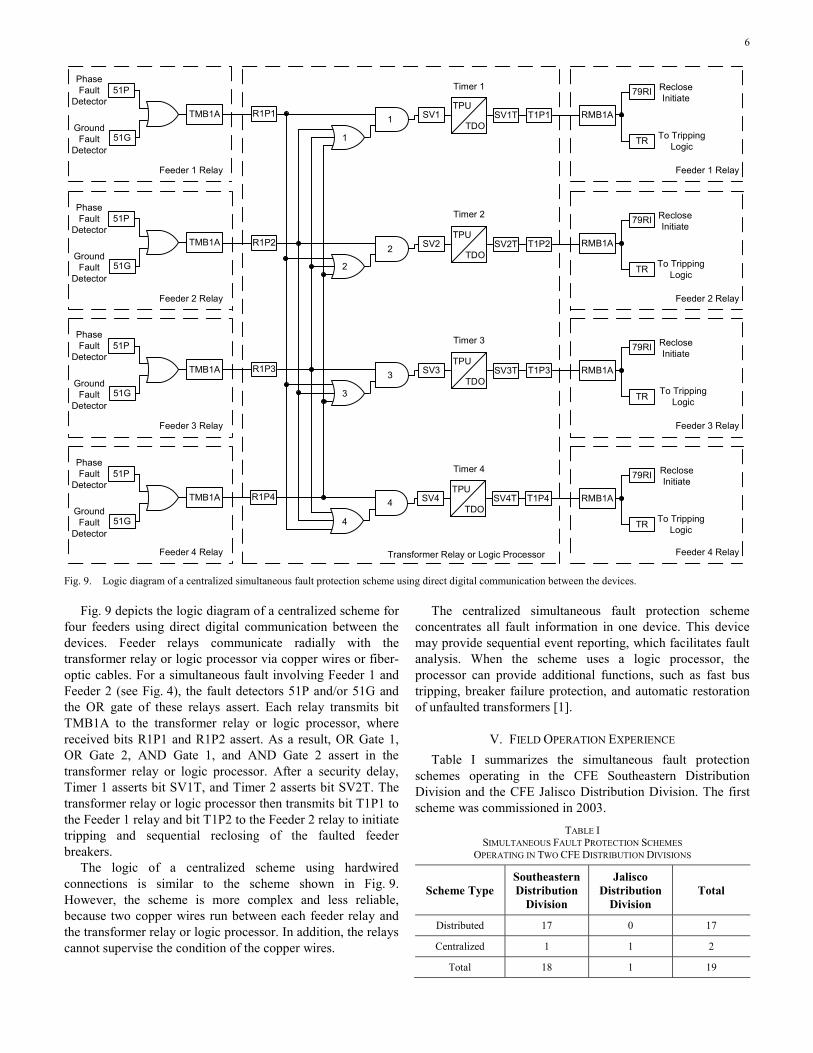
Fig. 9. Logic diagram of a centralized simultaneous fault protection scheme using direct digital communication between the devices.
Fig. 9 depicts the logic diagram of a centralized scheme for four feeders using direct digital communication between the devices. Feeder relays communicate radially with the transformer relay or logic processor via copper wires or fiber-optic cables. For a simultaneous fault involving Feeder 1 and Feeder 2 (see Fig. 4), the fault detectors 51P and/or 51G and the OR gate of these relays assert. Each relay transmits bit TMB1A to the transformer relay or logic processor, where received bits R1P1 and R1P2 assert. As a result, OR Gate 1, OR Gate 2, AND Gate 1, and AND Gate 2 assert in the transformer relay or logic processor. After a security delay, Timer 1 asserts bit SV1T, and Timer 2 asserts bit SV2T. The transformer relay or logic processor then transmits bit T1P1 to the Feeder 1 relay and bit T1P2 to the Feeder 2 relay to initiate tripping and sequential reclosing of the faulted feeder breakers.
The logic of a centralized scheme using hardwired connections is similar to the scheme shown in Fig. 9. However, the scheme is more complex and less reliable, because two copper wires run between each feeder relay and the transformer relay or logic processor. In addition, the relays cannot supervise the condition of the copper wires.
The centralized simultaneous fault protection scheme concentrates all fault information in one device. This device may provide sequential event reporting, which facilitates fault analysis. When the scheme uses a logic processor, the processor can provide additional functions, such as fast bus tripping, breaker failure protection, and automatic restoration of unfaulted transformers [1].
V. FIELD OPERATION EXPERIENCE Table I summarizes the simultaneous fault protection
schemes operating in the CFE Southeastern Distribution Division and the CFE Jalisco Distribution Division. The first scheme was commissioned in 2003.
TABLE I SIMULTANEOUS FAULT PROTECTION SCHEMES
OPERATING IN TWO CFE DISTRIBUTION DIVISIONS
Scheme Type Southeastern Distribution
Division
Jalisco Distribution
Division Total
Distributed 17 0 17
Centralized 1 1 2
Total 18 1 19

7
Fig. 10. Simplified one-line diagram of the Oaxaca Uno Substation.
These schemes have operated correctly for all 46 simultaneous faults that have occurred on feeders of both distribution divisions. The causes of the faults are as follows:
• Faults in double-circuit lines: 20 • Thunderstorms: 19 • Faults during circuit-looped operation: 7
No scheme misoperations have occurred for faults involving only one feeder, cold load pickup conditions, or other abnormal conditions.
VI. EXAMPLE OF SCHEME OPERATION FOR AN ACTUAL FAULT
A. Scheme Operation Analysis The Oaxaca Uno Substation (see Fig. 10), located in the
city of Oaxaca de Juárez, state of Oaxaca, Mexico, has a 12/16/20 MVA, 115/13.8 kV transformer and an 18/24/30 MVA, 115/13.8 kV transformer. Each transformer feeds four radial feeders. This substation has a centralized simultaneous fault protection scheme using a protection processor and direct digital communication between the devices.
During a severe thunderstorm on May 18, 2009, a temporary phase-to-phase simultaneous fault occurred on
distribution feeders OAX-4010 and OAX-4020. The fault current contributions were 2,001 A on the OAX-4010 feeder and 823 A on the OAX-4020 feeder. The prefault demands were 5.9 MVA on the OAX-4010 feeder, 6.8 MVA on the OAX-4020 feeder, and 28.9 MVA on the transformer.
From the sequential event report of the OAX-4010 feeder relay (see Fig. 11), we conclude the following:
• The phase fault detector 51P operated at 20:29:16.918 hours.
• The feeder relay transmitted fault detection information (bit TMB1A asserted) to the logic processor at 20:29:16.918 hours.
• The feeder relay received a tripping command (bit RMB1A asserted) from the logic processor at 20:29:17.051 hours.
• The feeder relay sent a trip signal to the breaker (bit TRIP asserted) at 20:29:17.055 hours.
• The breaker opened (bit 52A deasserted) at 20:29:17.130 hours. Breaker operating time is 75 milliseconds (4.5 cycles).
The sequential event report of the OAX-4020 feeder relay is almost identical to the report shown in Fig. 11.

8
Fig. 11. Sequential event report of the OAX-4010 feeder relay.
From the sequential event report of the logic processor (Fig. 12), we conclude that the processor:
• Received fault detection information from the OAX-4010 feeder relay (bit R1P1 asserted) at 20:29:16.941 hours.
• Received fault detection information from the OAX-4020 feeder relay (bit R1P2 asserted) at 20:29:16.953 hours.
• Declared a simultaneous fault involving the OAX-4010 feeder (bit SV5 asserted) at 20:29:16.953 hours.
• Declared a simultaneous fault involving the OAX-4020 feeder (bit SV6 asserted) at 20:29:16.953 hours.
• Sent a tripping signal to the OAX-4010 feeder relay (bit T1P1 asserted) at 20:29:17.053 hours when the timer expired (bit SV5T asserted). Timer pickup setting is 100 milliseconds (6 cycles).
• Sent a tripping signal to the OAX-4020 feeder relay (bit T1P2 asserted) at 20:29:17.053 hours when the timer expired (bit SV6T asserted). Timer pickup setting is 100 milliseconds (6 cycles).
Fig. 12. Sequential event report of the logic processor.
From the oscillogram recorded by the OAX-4010 feeder relay (Fig. 13), we conclude the following:
• The fault started on Cycle 3.0. • The phase fault detector 51P operated on Cycle 3.75. • The feeder relay closed its contact (OUT 12 asserted)
on Cycle 12. • The scheme operating time was 9 cycles. • The total fault-clearing time was 13.5 cycles (given a
4.5-cycle breaker operating time). The oscillogram recorded by the OAX-4020 feeder relay is
almost identical to the oscillogram shown in Fig. 13.
Fig. 13. Oscillogram recorded by the OAX-4010 feeder relay.

9
B. Cost Analysis For the actual temporary fault discussed previously, the
simultaneous fault protection scheme avoided transformer breaker misoperation, and the faulted feeder breakers successfully reclosed.
This fault could have caused the transformer low-voltage-side breaker to misoperate if the Oaxaca Uno Substation lacked a simultaneous fault protection scheme. Transformer breaker misoperation would have caused all transformer loads to lose service. Operation personnel would have had to travel to the substation to manually reclose the transformer breaker.
Assuming a transformer breaker misoperation for this fault, we can determine the cost of nonserved energy. When the fault occurred, the transformer load was 28.9 MVA, or 27.455 MW at a 0.95 power factor. If service restoration time equals 1 hour, the amount of nonserved energy is 27,455 kWh. Assuming an energy price of Mex$1.09/kWh, the cost of nonserved energy is Mex$29,926. If the cost of personnel travelling to the substation equals Mex$2,600, the total economic loss resulting from one fault that causes transformer breaker misoperation is Mex$32,526 (equivalent to US$2,502). The actual economic loss may be higher if the utility has to pay penalties for service interruption.
VII. CONCLUSIONS From the results presented in this paper, we conclude: • Causes of simultaneous faults involving two or more
overhead distribution feeders include multicircuit lines or lines sharing the same right of way, switching operations, and thunderstorms.
• Simultaneous faults may cause misoperation of the time-delayed overcurrent elements of the transformer low-voltage-side relay.
• Simultaneous fault protection schemes prevent transformer low-voltage-side breaker misoperations. These schemes improve service quality by avoiding unnecessary service interruptions to the unfaulted feeders.
• In distributed schemes, the simultaneous fault protection logic resides in the feeder relays; in centralized schemes, the logic resides in the transformer low-voltage-side relay or logic processor.
• The CFE Southeastern Distribution Division and the CFE Jalisco Distribution Division have 19 simultaneous fault protection schemes in operation; these schemes have correctly cleared all 46 simultaneous faults. No scheme misoperations have occurred so far.
VIII. REFERENCE [1] D. Sánchez, E. Alcázar, O. Márquez, H. Altuve, and A. Martínez,
“Multifunction Relays and Protection Logic Processors in Distribution Substation Applications.” Available: http://www.selinc.com.
IX. BIOGRAPHIES Jorge Betanzos Manuel received his BSEE degree in Electrical and Industrial Engineering from the Oaxaca Technological Institute in 1983. He joined Comisión Federal de Electricidad (CFE) in 1984 as a construction supervisor in the Southeastern Distribution Division (SDD). From 1986 until 1993, he was a protection, control, and metering engineer at the Istmo and Malpaso Transmission Zones of the CFE Southeastern Transmission Region. From 1993 until 1997, Mr. Betanzos was head of the Protection Office of the Oaxaca Distribution Zone. From 1997 until 2000, he was head of the Office for High-Voltage Network Studies of the SDD Planning Department. Since 2000, Mr. Betanzos has worked as head of the Protection Department of the CFE SDD. He leads projects on power quality monitoring and modernizing protection, control, and metering panels in the CFE SDD.
Héctor E. Lemus Zavala received his BSEE degree in Electromechanical Engineering from the University of Guadalajara, Mexico. In 1999, he joined Comisión Federal de Electricidad (CFE), where he was supervisor of the Jalisco Distribution Division (JDD). Since 2007, he has worked as head of the Protection Office of the CFE JDD in Guadalajara, Jalisco, Mexico. His activities include supervision, maintenance, improvement, and commissioning of protection and control systems for distribution substations. He was a member of the Committee of Distribution Protection Specialists and the Permanent Protection Committee (CFE Transmission). Mr. Lemus is currently a member of the Regional Protection Committee of the CFE Operation Division.
Eliseo Alcázar Ramírez received his BSEE degree from the Oaxaca Technological Institute in 1998. From 1999 until 2001, he was head of the Protection, Control, and Metering Department in the Southeastern Distribution Division (SDD) of Comisión Federal de Electricidad (CFE) in Tehuantepec, Mexico. From 2001 until 2004, he was head of the Protection Office of the CFE SDD. During this time, he was engaged in activities of supervision, maintenance, improvement, and commissioning of protection, control, and metering systems. His expertise includes fault analysis, short-circuit studies, protection coordination, and protection system design. In April 2004, Mr. Alcázar joined Schweitzer Engineering Laboratories, Inc. (SEL), where he is currently a protection engineering supervisor in San Luis Potosí, Mexico. His activities include protection, control, and metering system design and commissioning, as well as technical support and training on SEL products for engineers from utilities and industrial plants.
David Sánchez Escobedo received his BSEE degree in 1994 from the University of Guanajuato, Mexico, and his M.Sc. degree in 2005 from the University of Guadalajara, Mexico. From 1994 until 1998, he was head of the Protection and Metering Office in the Western Transmission Area of Comisión Federal de Electricidad (CFE) in Guadalajara, Jalisco, Mexico. Mr. Sánchez served on the faculty of the Autonomous University of Guadalajara in 1998. From 1998 until 2000, he worked for INELAP-PQE in Guadalajara, Mexico, as a protection system design engineer. In September 2000, Mr. Sánchez joined Schweitzer Engineering Laboratories, Inc., where he is currently the electrical engineering manager in San Luis Potosí, Mexico. He has authored and coauthored several technical papers.
Héctor J. Altuve received his BSEE degree in 1969 from the Central University of Las Villas in Santa Clara, Cuba, and his Ph.D. in 1981 from Kiev Polytechnic Institute in Kiev, Ukraine. From 1969 until 1993, Dr. Altuve served on the faculty of the Electrical Engineering School at the Central University of Las Villas. From 1993 to 2000, he served as professor of the Graduate Doctoral Program in the Mechanical and Electrical Engineering School at the Autonomous University of Nuevo León in Monterrey, Mexico. In 1999 through 2000, he was the Schweitzer Visiting Professor in the Department of Electrical Engineering at Washington State University. Dr. Altuve joined Schweitzer Engineering Laboratories, Inc. in January 2001, where he is currently a distinguished engineer and director of technology for Latin America. He has authored and coauthored more than 100 technical papers and holds three patents. His main research interests are in power system protection, control, and monitoring. Dr. Altuve is an IEEE senior member and an IEEE Power Engineering Society distinguished lecturer.
Previously presented at the 2010 Texas A&M Conference for Protective Relay Engineers.
© 2010 IEEE – All rights reserved. 20100120 • TP6414-01