Embed Size (px)
Citation preview
Data Sheet
© 2009 Cisco Systems, Inc. All rights reserved. This document is Cisco Public Information. Page 1 of 62
Protecting Cisco Catalyst 6500 Series Switches Using Control Plane Policing, Hardware Rate Limiting, and Access-Control Lists
A CSSTG SE Residency Program
Ray Blair, VSA
David Prall, CSE
It’s been some time since administrators focused their security attention primarily on servers and hosts in the
network. At that time administrators didn’t use much more than a firewall and a few access lists to secure an entire
network. Over the last several years, the infrastructure has also become a direct target, and on many occasions, an
attack on the network is a byproduct of a worm or virus. Infected hosts generate substantial traffic either by scanning
other hosts in the network, proliferating malware, and/or being the target of an attack or potentially being in the path
of the attack. In order to protect the infrastructure, especially the core and distribution portions of the network, other
mechanisms can be used to minimize the effects on these critical business-enabling components, namely, your
Cisco® Catalyst® 6500 Series Switches.
This paper describes three methods that can be employed to help protect your infrastructure: control-plane policing
(CoPP), hardware rate limiting (HWRL), and access-control lists (ACLs). The operation of each function and
configuration examples of each of these methods will be explained in detail, so you will have an understanding of
how to successfully implement these valuable features.
Through the use of a controlled test environment, several attack situations were created that placed the network
infrastructure in jeopardy. The effects on the network were captured and, using the methods previously described,
these attacks were mitigated and the condition of the network was captured. Configuration examples will be used to
show how an unprotected infrastructure behaves. The appropriate configurations that mitigate the attack will then be
shown.
Finally, a baseline recommendation will be provided as a starting point from which you can begin implementation of
control plane protection in your network.
Overview
The performance of the switch is limited by what can be processed in purpose-built hardware application-specific
integrated circuits (ASICs) and what can be processed on the switch central processing unit (CPU) by software. Data
plane and control plane performance are terms used to describe these performance metrics, respectively. Although
the Cisco Catalyst 6500 Supervisor 32 and Supervisor 720 have tremendous capability integrated directly into the
hardware, there are specific data types that can only be processed by the switch control plane. Examples of data
that can only be processed by the control plane include routing control protocol, Bridge Protocol data unit (BPDU),
Cisco Discovery Protocol, Internet Control Message Protocol (ICMP), or packets with IP options, traffic destined to
an IP address of the switch, and management traffic. When too much traffic is redirected to the switch control plane,
the CPU can become overwhelmed, resulting in the control plane’s inability to perform all required tasks. This
condition may not only effect this individual chassis, but other devices within the network. To minimize the effects on
control plane performance, a combination of CoPP, hardware rate limiters, and ACLs can be used to reduce the flow
of control plane bound traffic, thus keeping the performance of the control plane from being compromised.
Data Sheet
© 2009 Cisco Systems, Inc. All rights reserved. This document is Cisco Public Information. Page 2 of 62
The objective of this paper is to present best practices to protect the Cisco Catalyst 6500 control plane against either
malicious or inadvertent attacks and/or misconfigurations or component failures. These best practices offer a
comprehensive approach for control plane protection through the use of CoPP, HWRL, and ACLs. This document
will explain the functionality of CoPP, HWRL, and the use of ACLs to reduce overall traffic loads destined to the
control plane and mitigate attacks that could compromise the operational integrity of the switch control plane.
Technical Introduction to CoPP
The control plane of the Cisco Catalyst 6500 is operated and serviced by two discrete CPUs: the route processor
and the switch processor. The route processor is primarily responsible for Layer 3 control plane functions, while the
switch processor is responsible for Layer 2 control plane functions. The route processor and switch processor have
other responsibilities as well. For example, the route processor is the default CPU for managing the CLI for typical
administration operations, while the switch processor is responsible for programming the hardware tables with
routing information, quality of service (QoS), security ACLs, and more. The switch control plane is a very important
component that is critical in maintaining ongoing switch operations. If the control plane is overwhelmed, then it can
have a direct effect on the operational integrity of the switch. Examples of the effect such a situation can have
include:
● Control plane packet queue overruns leading to packet drops for control plane bound traffic
● Control plane protocols such as routing protocols dropping neighbors causing reconvergence in the network
● Loss of line protocol keep-alive messages
● Slow down in the ability to update hardware tables with up to date state information
● Exhaustion of control plane resources like memory and packet buffers
● Unresponsive CLI for telnet and console sessions
CoPP provides a mechanism in which QoS policies can be applied to traffic destined for the control plane of the
Cisco Catalyst 6500. This facility can protect the operational integrity of the control plane to help ensure a stable and
reliable operating environment for the control plane to work with. When implementing CoPP, the modular QoS
command-line interface (MQC) is used to configure a service policy, which is then used to apply these policies to the
control plane.
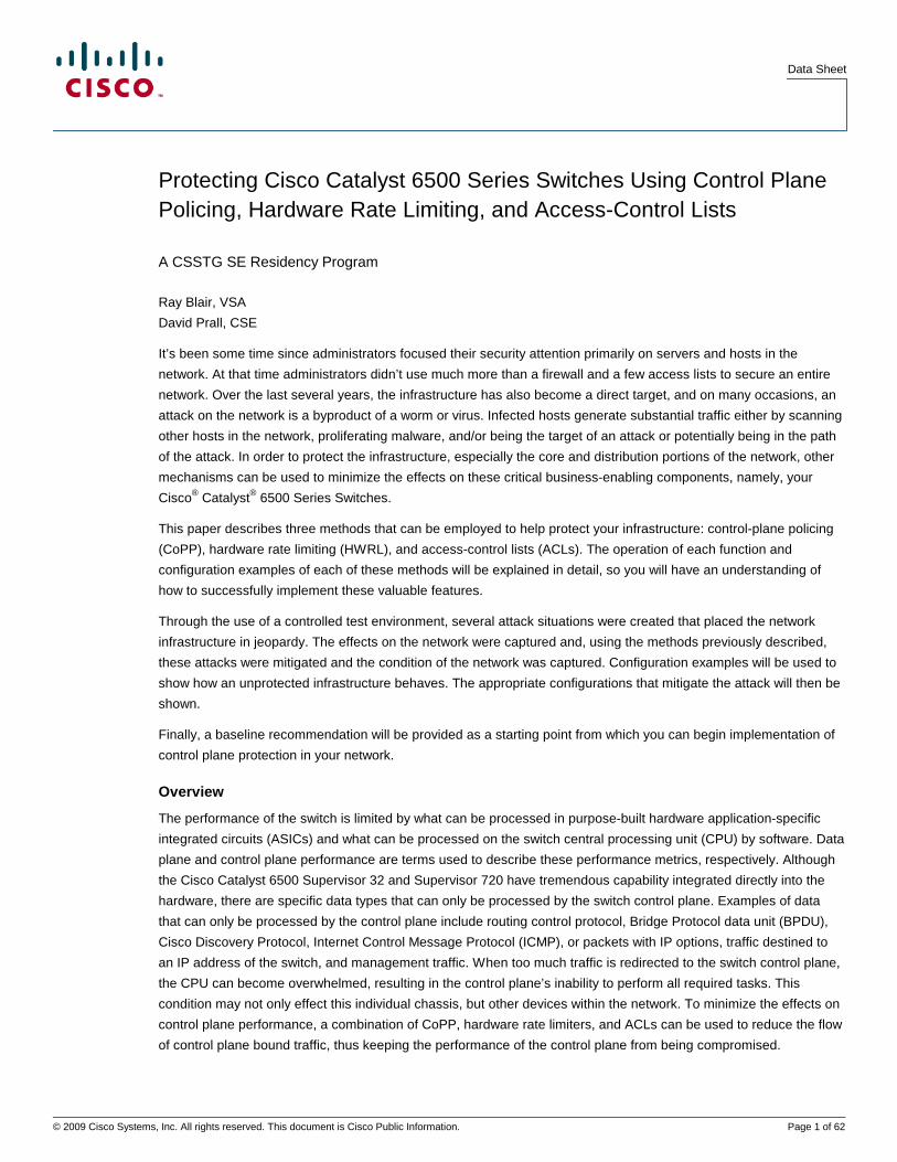
CoPP is implemented in hardware and/or software depending on the configuration. The hardware function for CoPP
is distributed across the policy feature card (PFC) on the supervisor and individual line cards that have a distributed
forwarding card (DFC). The supervisor controls the hardware policing from “classic” line cards (for example, WS-
X61xx line cards) and line cards with a centralized forwarding card (CFC) (for example, WS-X67xx line cards). When
CoPP is employed in hardware, there is no effect to the performance of the switch overall or the switch control plane.
The software component of CoPP is handled by the route processor on the supervisor and has the potential to affect
the CPU. The following diagram shows where the hardware and software components for CoPP are implemented
(relevant hardware components are highlighted in red).
Data Sheet
© 2009 Cisco Systems, Inc. All rights reserved. This document is Cisco Public Information. Page 3 of 62
Figure 1.
A CoPP policy can limit a number of different packet types that are forwarded to the control plane. Traffic destined
for the switch CPU includes:
● Address Resolution Protocol (ARP)
● First-hop redundancy protocol packets
● Layer 2 control packets
● Management packets (telnet, Secure Shell [SSH] Protocol, Simple Network Management Protocol [SNMP])
● Multicast control packets
● Routing protocol packets
● Packets with IP options
● Packets with time to live (TTL) set to 1
● Packets that require ACL logging
● Packets that require an initial lookup (first packet in a flow: FIB miss)
● Packets that have don’t support hardware switching/routing
Not all of the traffic types defined above can be handled by the hardware CoPP component and thus can still have
an effect on control plane performance. More details on this are covered later in the document.
Let’s look at an example of how to configure and apply a CoPP policy on the switch. The first step in configuring
CoPP requires QoS to be globally enabled on the switch. Enabling QoS on the switch requires the “mls qos”
command to be applied, as shown in the following example:
Switch(config)#mls qos
The next step requires building an ACL to match interesting traffic (control plane bound traffic that needs to be
limited). For the purposes of this example, a match on SNMP traffic from host 10.1.0.254, telnet and SSH from
10.1.0.3, and Network Time Protocol (NTP) from 10.200.200.200 is used as shown in the following ACL block:
Switch(config)#ip access-list extended Management_Good_ACL
Switch(config-ext-nacl)#permit udp host 10.1.0.254 any eq snmp
Switch(config-ext-nacl)#permit tcp host 10.1.0.3 any eq telnet
Switch(config-ext-nacl)#permit tcp host 10.1.0.3 any eq 22
Switch(config-ext-nacl)#permit udp host 10.200.200.200 any eq ntp
Data Sheet
© 2009 Cisco Systems, Inc. All rights reserved. This document is Cisco Public Information. Page 4 of 62
Following the creation of the ACL, a class map should be constructed that uses the previously created ACL to match
traffic; an example of this is shown below:
Switch(config)#class-map match-any Management_Good_Class
Switch(config-cmap)#match access-group name Management_Good_ACL
Finally, a policy map should be created that includes the class map information and specifies how the traffic will be
handled. In this example, 6Mb/s of management traffic is allowed to pass through to the CPU (the conform action),
and traffic that exceeds this limit will be dropped (the exceed action):
Switch(config)#policy-map CoPP_Policy
Switch(config-pmap)#class Management_Good_Class
Switch(config-pmap-c)#police 6000000 conform-action transmit exceed-action drop
That completes the configuration of a CoPP policy on a switch. The actual policy that an administrator would apply is
going to be dependent on the type and volume of control plane traffic that a given switch is required to process.
CoPP Limitations
To successfully implement CoPP, a thorough understanding of its limitations is required. As noted earlier, some
traffic is controlled by the hardware CoPP component, and this has no effect on performance. Other traffic, however,
is controlled by the software CoPP component, and this can have a significant effect on performance. The following
is a list of control plane bound traffic that is not controlled or rate limited by the hardware CoPP component:
● Non-IP traffic
● Interior Gateway Protocol (IGP) routing protocols because of their use of multicast
● Packets destined to an IP address that is locally terminated on the Cisco Catalyst 6500
● Network management traffic
● ICMP or traffic with IP options set
● Layer 2 traffic, including Cisco Discovery Protocol, Spanning Tree Protocol, Virtual LAN (VLAN) Trunking
Protocol (VTP), and others
● Egress QoS and CoPP cannot be configured at the same time with a PFC3A, otherwise CoPP is performed in
software
● CoPP is not enabled in hardware unless multilayer switching (MLS) QoS is enabled globally with the “mls
qos” command. In case the “mls qos” configuration is not entered, CoPP will only work in software, therefore
lacking any hardware benefit.
The following list is composed of functions that are not controlled by either hardware or software CoPP:
● Multicast and broadcast traffic
● ARP policies
● Support non-IP classes except for the default non-IP class (post SXE release only). ACLs can be used
instead to drop non-IP traffic, and the default non-IP CoPP class can be used to limit to non-IP traffic that
reaches the route processor CPU
● ACLs with the “log” keyword
● CoPP will ignore a class that does not have a corresponding policing action
● No support for MAC ACLs
Data Sheet
© 2009 Cisco Systems, Inc. All rights reserved. This document is Cisco Public Information. Page 5 of 62
There are some other caveats that must also be taken into consideration when formulating a control plane protection
policy. These include:
● CoPP does not permit multiple match criteria Pre- 12.2(18)SXE release
● Egress CoPP is not supported
● CoPP is disabled when egress policy is present with PFC3A
● Packets with an invalid version number need to be rate limited with a VLAN ACL (VACL) with MAC access
list.
● Currently CoPP can only be used on packets for which the input ACL logic or the FIB has decided the route
processor as the packet’s final destination. This implies that CoPP cannot currently be applied on packets for
which the egress processing (for example, egress ACL) determines the route processor as final destination.
● QoS ternary content-addressable memory (TCAM) resources are used for CoPP
● Selective packet discard may drop packets in software input interface queue after the CoPP software logic
can take effect; for example, CoPP happens at interrupt level, and then process level interface queues may
drop traffic
● Hardware CoPP is only supported in PFC3x based systems
● SNMP does not provide and insight into CoPP traffic statistics
● With TTL=1/maximum transmission unit (MTU) failure rate limit enabled, Layer 2 multicast bridging will not
function for PFC3a based systems
● Traffic will be double policed if it hits two hardware rate limiters
● Layer 2 rate limiters not supported in truncated mode
● No hardware rate limiter counters available. Note that global TTL failure and MTU failure counters are
available on PFC3B and PFC3BXL.
● IP options rate limiters only on PFC3B and 3BXL
● Hardware rate limiters per forwarding engines (aggregate for Layer 2 rate limiting)
● When using CoPP, it is strongly recommended to disable the “Cisco Express Forwarding receive” rate limiter.
● When combining CoPP and HWRL, HWRL always takes precedence over CoPP; for example, if HWRL is
applied in hardware, CoPP for the same traffic can only be applied in software. The exception is for HWRL
that is applied after packet rewrite in hardware (for example, only TTL=1 and MTU failure so far) since control
packets are excluded from this HWRL logic. In general, control plane packets hitting the bridge adjacency are
not affected by TTL and MTU rate limiting.
● If the TCAM is exhausted due to a large QoS configuration, CoPP will be performed in software
● Hardware CoPP will be disabled when using the following three commands:
mls rate-limit unicast cef receive
mls rate-limit unicast cef glean
mls rate-limit unicast acl input
Another situation that might overwhelm the CPU occurs even when “interesting” traffic matches the hardware rate
limiters. This condition exists in the following case where DFCs are installed in the chassis. The configuration
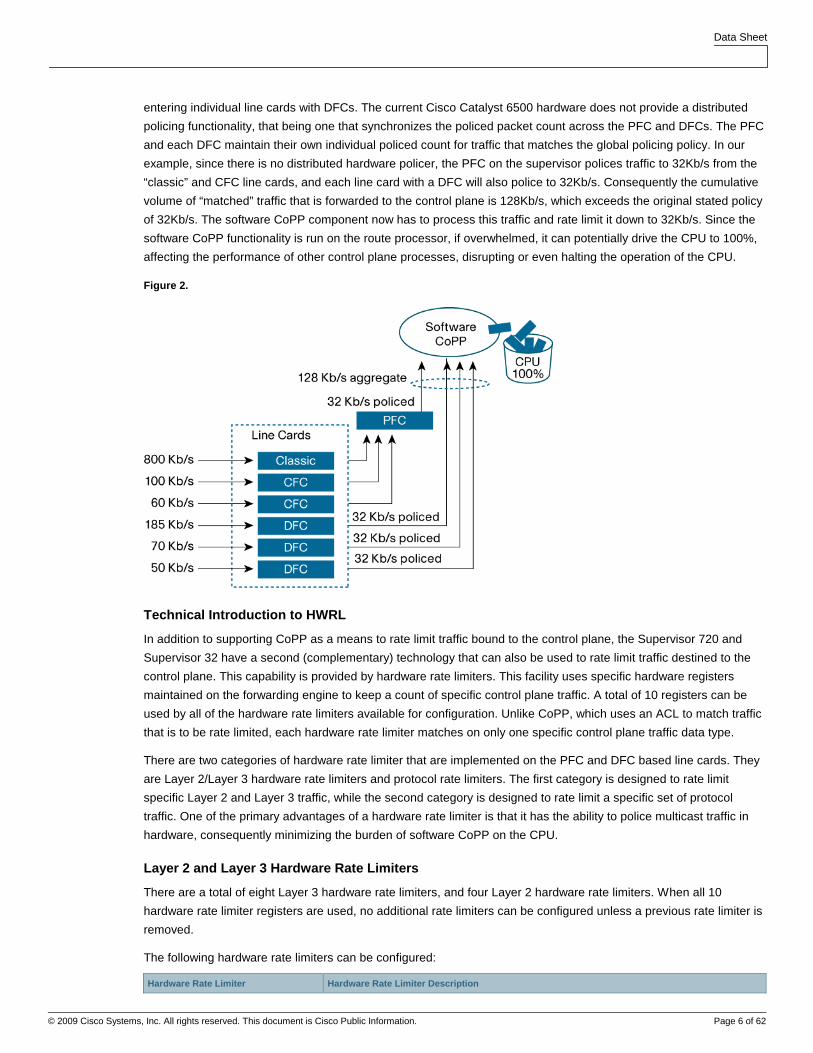
example below shows a 32Kb/s police action defined for interesting traffic:
Switch(config-pmap-c)#police 32000 conform-action transmit exceed-action drop
The switch processor will program the PFC and each DFC installed in the chassis with the same QoS policing policy.
As shown in the diagram below, there are 6 traffic streams entering the switch. An 80Kb/s stream to a “classic” card,
a 100Kb/s and 60Kb/s stream entering the cards with CFCs, and 3 traffic streams at 185Kb/s, 70Kb/s, and 50Kb/s
Data Sheet
© 2009 Cisco Systems, Inc. All rights reserved. This document is Cisco Public Information. Page 6 of 62
entering individual line cards with DFCs. The current Cisco Catalyst 6500 hardware does not provide a distributed
policing functionality, that being one that synchronizes the policed packet count across the PFC and DFCs. The PFC
and each DFC maintain their own individual policed count for traffic that matches the global policing policy. In our
example, since there is no distributed hardware policer, the PFC on the supervisor polices traffic to 32Kb/s from the
“classic” and CFC line cards, and each line card with a DFC will also police to 32Kb/s. Consequently the cumulative
volume of “matched” traffic that is forwarded to the control plane is 128Kb/s, which exceeds the original stated policy
of 32Kb/s. The software CoPP component now has to process this traffic and rate limit it down to 32Kb/s. Since the
software CoPP functionality is run on the route processor, if overwhelmed, it can potentially drive the CPU to 100%,
affecting the performance of other control plane processes, disrupting or even halting the operation of the CPU.
Figure 2.
Technical Introduction to HWRL
In addition to supporting CoPP as a means to rate limit traffic bound to the control plane, the Supervisor 720 and
Supervisor 32 have a second (complementary) technology that can also be used to rate limit traffic destined to the
control plane. This capability is provided by hardware rate limiters. This facility uses specific hardware registers
maintained on the forwarding engine to keep a count of specific control plane traffic. A total of 10 registers can be
used by all of the hardware rate limiters available for configuration. Unlike CoPP, which uses an ACL to match traffic
that is to be rate limited, each hardware rate limiter matches on only one specific control plane traffic data type.
There are two categories of hardware rate limiter that are implemented on the PFC and DFC based line cards. They
are Layer 2/Layer 3 hardware rate limiters and protocol rate limiters. The first category is designed to rate limit
specific Layer 2 and Layer 3 traffic, while the second category is designed to rate limit a specific set of protocol
traffic. One of the primary advantages of a hardware rate limiter is that it has the ability to police multicast traffic in
hardware, consequently minimizing the burden of software CoPP on the CPU.
Layer 2 and Layer 3 Hardware Rate Limiters
There are a total of eight Layer 3 hardware rate limiters, and four Layer 2 hardware rate limiters. When all 10
hardware rate limiter registers are used, no additional rate limiters can be configured unless a previous rate limiter is
removed.
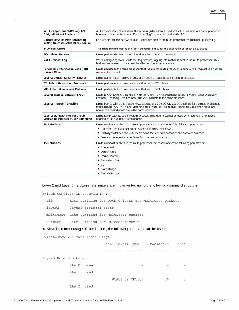
The following hardware rate limiters can be configured:
Hardware Rate Limiter Hardware Rate Limiter Description
Data Sheet
© 2009 Cisco Systems, Inc. All rights reserved. This document is Cisco Public Information. Page 7 of 62
Input, Output, and VACL-log ACL Bridged Unicast Packets
All hardware rate limiters share the same register and are used when ACL features are not supported in hardware, if the packet is non-IP, or if the “log” keyword is used on the ACL.
Unicast Reverse Path Forwarding (uRPF) Unicast Packet Check Failure
Packets that fail the hardware uRPF check are sent to the route processor for additional processing.
IP Unicast Errors This limits packets sent to the route processor if they fail the checksum or length calculations.
FIB Unicast Receive Limits packets destined for an IP address that is local to the switch.
VACL Unicast Log When configuring VACLs with the “log” feature, logging information is sent to the route processor. This feature can be used to minimize the effect on the route processor.
Forwarding Information Base (FIB) Unicast Glean
Limits packets to the route processor that require the route processor to send a ARP request to a host on a connected subnet.
Layer 3 Unicast Security Features Limits authentication-proxy, IPSec, and inspection packets to the route processor.
TTL failure Unicast and Multicast Limits packets to the route processor that fail the TTL check.
MTU failure Unicast and Multicast Limits packets to the route processor that fail the MTU check.
Layer 2 protocol data unit (PDU) Limits BPDU, Dynamic Trunking Protocol (DTP), Port Aggregation Protocol (PAgP), Cisco Discovery Protocol, Spanning Tree Protocol, and VTP packets to the route processor.
Layer 2 Protocol Tunneling Limits frames with a destination MAC address of 01-00-0C-CD-CD-D0 destined for the route processor, these include PDU, VTP, and Spanning Tree Protocol. This feature cannot be used when fabric and nonfabric enabled cards are in the same chassis.
Layer 2 Multicast Internet Group Messaging Protocol (IGMP) Snooping
Limits IGMP packets to the route processor. This feature cannot be used when fabric and nonfabric enabled cards are in the same chassis.
IPv4 Multicast Limits multicast packets to the route processor that match one of the following parameters:
● FIB-miss – packets that do not have a FIB entry (new flows).
● Partially switched flows – multicast flows that are both hardware and software switched.
● Directly connected – limits flows from connected sources.
IPv6 Multicast Limits multicast packets to the route processor that match one of the following parameters:
● Connected
● Default-Drop
● Route-Control
● Secondary-Drop
● SG
● Starg-Bridge
● Starg-M-Bridge
Layer 2 and Layer 3 hardware rate limiters are implemented using the following command structure:
Switch(config)#mls rate-limit ?
all Rate Limiting for both Unicast and Multicast packets
layer2 layer2 protocol cases
multicast Rate limiting for Multicast packets
unicast Rate limiting for Unicast packets
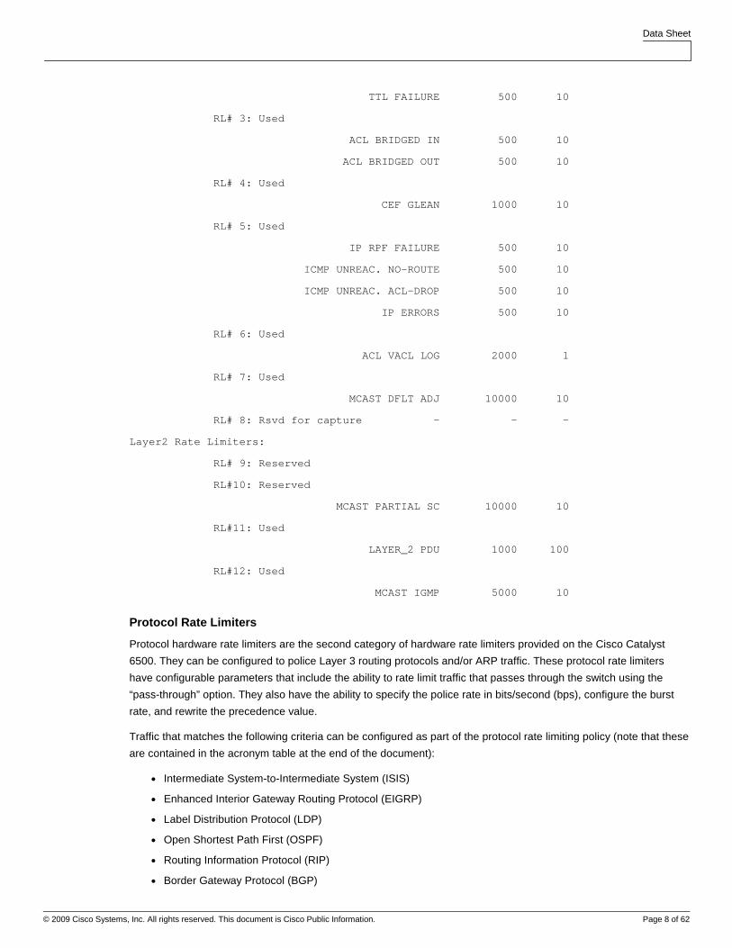
To view the current usage of rate limiters, the following command can be used:
Switch#show mls rate-limit usage
Rate Limiter Type Packets/s Burst
--------------------- --------- -----
Layer3 Rate Limiters:
RL# 0: Free - - -
RL# 1: Used
UCAST IP OPTION 10 1
RL# 2: Used
Data Sheet
© 2009 Cisco Systems, Inc. All rights reserved. This document is Cisco Public Information. Page 8 of 62
TTL FAILURE 500 10
RL# 3: Used
ACL BRIDGED IN 500 10
ACL BRIDGED OUT 500 10
RL# 4: Used
CEF GLEAN 1000 10
RL# 5: Used
IP RPF FAILURE 500 10
ICMP UNREAC. NO-ROUTE 500 10
ICMP UNREAC. ACL-DROP 500 10
IP ERRORS 500 10
RL# 6: Used
ACL VACL LOG 2000 1
RL# 7: Used
MCAST DFLT ADJ 10000 10
RL# 8: Rsvd for capture - - -
Layer2 Rate Limiters:
RL# 9: Reserved
RL#10: Reserved
MCAST PARTIAL SC 10000 10
RL#11: Used
LAYER_2 PDU 1000 100
RL#12: Used
MCAST IGMP 5000 10
Protocol Rate Limiters
Protocol hardware rate limiters are the second category of hardware rate limiters provided on the Cisco Catalyst
6500. They can be configured to police Layer 3 routing protocols and/or ARP traffic. These protocol rate limiters
have configurable parameters that include the ability to rate limit traffic that passes through the switch using the
“pass-through” option. They also have the ability to specify the police rate in bits/second (bps), configure the burst
rate, and rewrite the precedence value.
Traffic that matches the following criteria can be configured as part of the protocol rate limiting policy (note that these
are contained in the acronym table at the end of the document):
● Intermediate System-to-Intermediate System (ISIS)
● Enhanced Interior Gateway Routing Protocol (EIGRP)
● Label Distribution Protocol (LDP)
● Open Shortest Path First (OSPF)
● Routing Information Protocol (RIP)
● Border Gateway Protocol (BGP)
Data Sheet
© 2009 Cisco Systems, Inc. All rights reserved. This document is Cisco Public Information. Page 9 of 62
● Hot Standby Router Protocol (HSRP)
● OSPFv3
● BGPv2
● Routing Information Protocol Next Generation (RIPNG)
● Neighbor-Discovery
● Wireless LAN Context Control Protocol (WLCCP)
● Resource Reservation Protocol (RSVP)
● RSVPv6
● ARP
Protocol rate limiters are implemented with the following beginning command structure:
Switch(config)#mls qos protocol ?
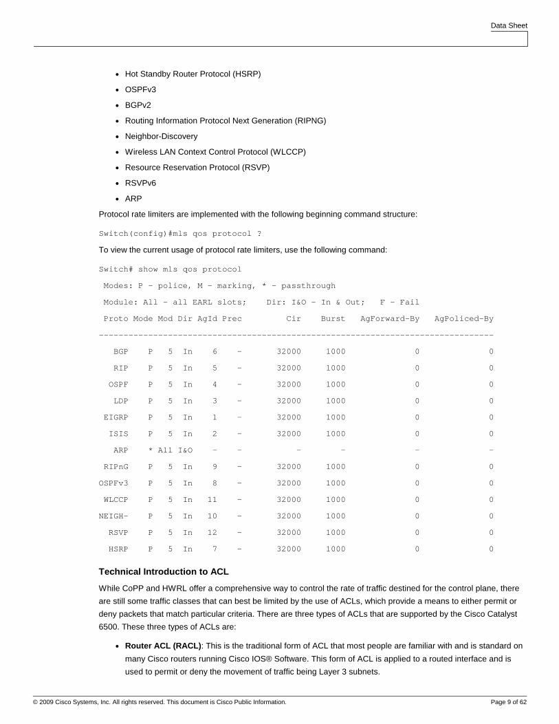
To view the current usage of protocol rate limiters, use the following command:
Switch# show mls qos protocol
Modes: P - police, M - marking, * - passthrough
Module: All - all EARL slots; Dir: I&O - In & Out; F - Fail
Proto Mode Mod Dir AgId Prec Cir Burst AgForward-By AgPoliced-By
--------------------------------------------------------------------------------
BGP P 5 In 6 - 32000 1000 0 0
RIP P 5 In 5 - 32000 1000 0 0
OSPF P 5 In 4 - 32000 1000 0 0
LDP P 5 In 3 - 32000 1000 0 0
EIGRP P 5 In 1 - 32000 1000 0 0
ISIS P 5 In 2 - 32000 1000 0 0
ARP * All I&O - - - - - -
RIPnG P 5 In 9 - 32000 1000 0 0
OSPFv3 P 5 In 8 - 32000 1000 0 0
WLCCP P 5 In 11 - 32000 1000 0 0
NEIGH- P 5 In 10 - 32000 1000 0 0
RSVP P 5 In 12 - 32000 1000 0 0
HSRP P 5 In 7 - 32000 1000 0 0
Technical Introduction to ACL
While CoPP and HWRL offer a comprehensive way to control the rate of traffic destined for the control plane, there
are still some traffic classes that can best be limited by the use of ACLs, which provide a means to either permit or
deny packets that match particular criteria. There are three types of ACLs that are supported by the Cisco Catalyst
6500. These three types of ACLs are:
● Router ACL (RACL) : This is the traditional form of ACL that most people are familiar with and is standard on
many Cisco routers running Cisco IOS® Software. This form of ACL is applied to a routed interface and is
used to permit or deny the movement of traffic being Layer 3 subnets.
Data Sheet
© 2009 Cisco Systems, Inc. All rights reserved. This document is Cisco Public Information. Page 10 of 62
● VLAN ACL (VACL) : This is a form of ACL that is applied to a VLAN or Switched Virtual interface (as opposed
to a “routed” Layer 3 interface). The VACL can match on either IPv4 packets or MAC frames. It has one major
benefit over an RACL and that is that it can limit the movement of traffic that is bridged within the VLAN. This
is a capability that an RACL does not have. The VACL is applied twice, once to traffic entering the VLAN and
once to traffic leaving the VLAN.
● Port ACL (PACL) : The PACL is similar in operation and use to a VACL; however, a PACL can only be
applied to Layer 2 (switch port) interfaces matching either IPv4 packets or MAC frames. Unlike a VACL, the
PACL is applied only on ingress traffic entering the switch port.
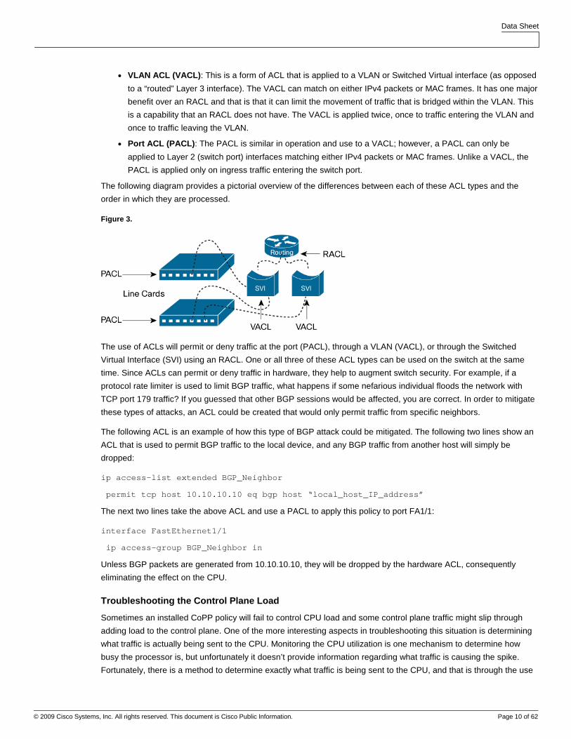
The following diagram provides a pictorial overview of the differences between each of these ACL types and the
order in which they are processed.
Figure 3.
The use of ACLs will permit or deny traffic at the port (PACL), through a VLAN (VACL), or through the Switched
Virtual Interface (SVI) using an RACL. One or all three of these ACL types can be used on the switch at the same
time. Since ACLs can permit or deny traffic in hardware, they help to augment switch security. For example, if a
protocol rate limiter is used to limit BGP traffic, what happens if some nefarious individual floods the network with
TCP port 179 traffic? If you guessed that other BGP sessions would be affected, you are correct. In order to mitigate
these types of attacks, an ACL could be created that would only permit traffic from specific neighbors.
The following ACL is an example of how this type of BGP attack could be mitigated. The following two lines show an
ACL that is used to permit BGP traffic to the local device, and any BGP traffic from another host will simply be
dropped:
ip access-list extended BGP_Neighbor
permit tcp host 10.10.10.10 eq bgp host “local_host_IP_address”
The next two lines take the above ACL and use a PACL to apply this policy to port FA1/1:
interface FastEthernet1/1
ip access-group BGP_Neighbor in
Unless BGP packets are generated from 10.10.10.10, they will be dropped by the hardware ACL, consequently
eliminating the effect on the CPU.
Troubleshooting the Control Plane Load
Sometimes an installed CoPP policy will fail to control CPU load and some control plane traffic might slip through
adding load to the control plane. One of the more interesting aspects in troubleshooting this situation is determining
what traffic is actually being sent to the CPU. Monitoring the CPU utilization is one mechanism to determine how
busy the processor is, but unfortunately it doesn’t provide information regarding what traffic is causing the spike.
Fortunately, there is a method to determine exactly what traffic is being sent to the CPU, and that is through the use
Data Sheet
© 2009 Cisco Systems, Inc. All rights reserved. This document is Cisco Public Information. Page 11 of 62
of a Switched Port Analyzer (SPAN) session. SPAN provides a way to replicate (take a copy) traffic and forward that
copy to an attached sniffer or probe.
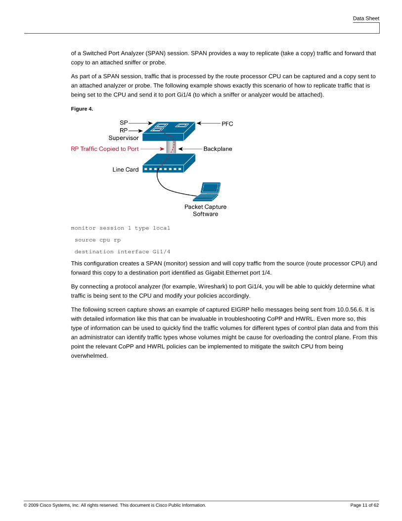
As part of a SPAN session, traffic that is processed by the route processor CPU can be captured and a copy sent to
an attached analyzer or probe. The following example shows exactly this scenario of how to replicate traffic that is
being set to the CPU and send it to port Gi1/4 (to which a sniffer or analyzer would be attached).
Figure 4.
monitor session 1 type local
source cpu rp
destination interface Gi1/4
This configuration creates a SPAN (monitor) session and will copy traffic from the source (route processor CPU) and
forward this copy to a destination port identified as Gigabit Ethernet port 1/4.
By connecting a protocol analyzer (for example, Wireshark) to port Gi1/4, you will be able to quickly determine what
traffic is being sent to the CPU and modify your policies accordingly.
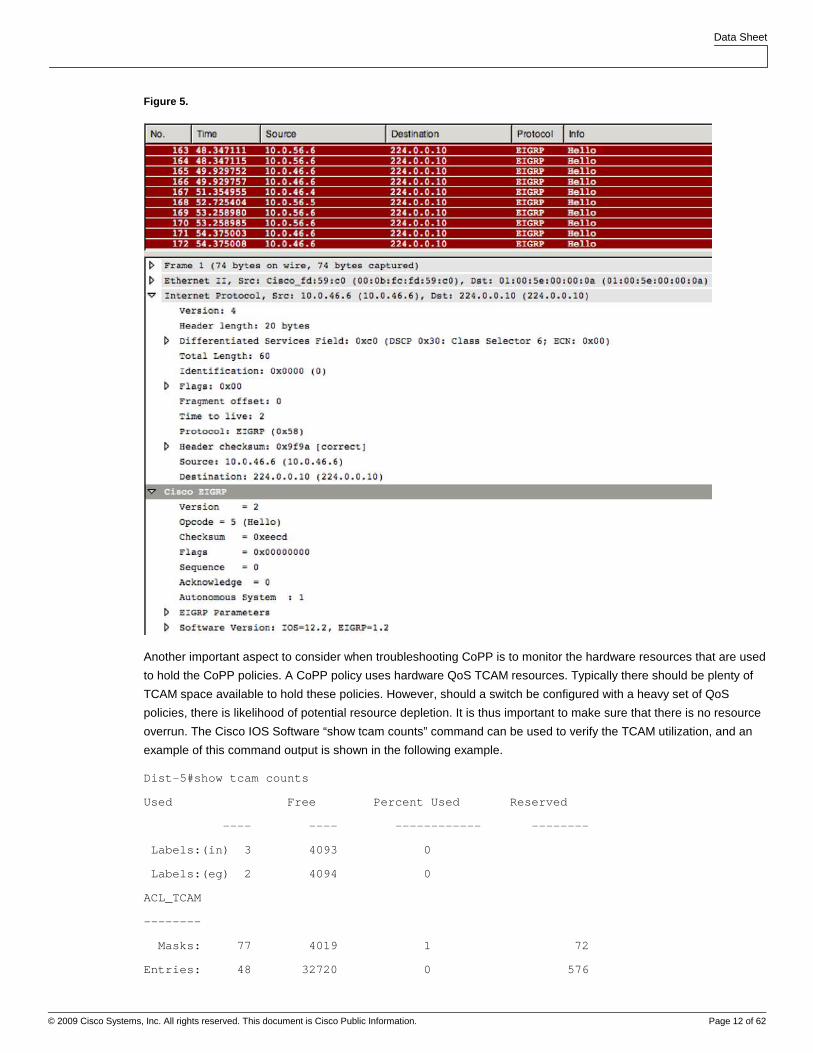
The following screen capture shows an example of captured EIGRP hello messages being sent from 10.0.56.6. It is
with detailed information like this that can be invaluable in troubleshooting CoPP and HWRL. Even more so, this
type of information can be used to quickly find the traffic volumes for different types of control plan data and from this
an administrator can identify traffic types whose volumes might be cause for overloading the control plane. From this
point the relevant CoPP and HWRL policies can be implemented to mitigate the switch CPU from being
overwhelmed.
Data Sheet
© 2009 Cisco Systems, Inc. All rights reserved. This document is Cisco Public Information. Page 12 of 62
Figure 5.
Another important aspect to consider when troubleshooting CoPP is to monitor the hardware resources that are used
to hold the CoPP policies. A CoPP policy uses hardware QoS TCAM resources. Typically there should be plenty of
TCAM space available to hold these policies. However, should a switch be configured with a heavy set of QoS
policies, there is likelihood of potential resource depletion. It is thus important to make sure that there is no resource
overrun. The Cisco IOS Software “show tcam counts” command can be used to verify the TCAM utilization, and an
example of this command output is shown in the following example.
Dist-5#show tcam counts
Used Free Percent Used Reserved
---- ---- ------------ --------
Labels:(in) 3 4093 0
Labels:(eg) 2 4094 0
ACL_TCAM
--------
Masks: 77 4019 1 72
Entries: 48 32720 0 576
Data Sheet
© 2009 Cisco Systems, Inc. All rights reserved. This document is Cisco Public Information. Page 13 of 62
QOS_TCAM
--------
Masks: 22 4074 0 18
Entries: 23 32745 0 144
LOU: 0 128 0
ANDOR: 0 16 0
ORAND: 0 16 0
ADJ: 3 2045 0
To understand each of these resources noted in the above table, let’s quickly look at an ACL set and explain where
and how these resources are consumed.
access-list 101 permit ip 10.1.1.0 0.0.0.255 host 192.168.1.10
access-list 101 permit tcp 10.5.12.0 0.0.0.255 host 192.168.5.100
access-list 101 permit ip 10.100.1.0 0.0.0.255 host 192.168.3.50
access-list 102 permit tcp 10.2.1.0 0.0.0.255 host 192.168.15.25 neq 23
access-list 102 permit ip 10.3.0.0 0.0.255.255 host 192.168.100.40
In this group of access lists the following TCAM resources would be used:
● A total of 5 QoS_TCAM entries (there are 5 lines above)
● A total of two labels are used (label 101 and 102)
● A total of three masks are used (host, 0.0.0.255 and 0.0.255.255)
● A total of 1 LOU is used (with the neq “not equal” operand in the second last entry)
Control Plane Protection Scenarios
There are several mechanisms that can be used to help protect against network attacks, including CoPP, rate
limiting, and ACLs. Each method addresses specific needs, but when used in combination, provide a holistic
approach to protecting the network infrastructure. Caution must be used to discriminate between good and bad
traffic, or the attempt to control “bad” traffic may effect legitimate traffic. The following configuration guidelines will
help to set an appropriate baseline.
The following network diagram was used as a test-bed for the following situations.
Test 1 – SNMP
Test 2 – Telnet
Test 3 – HSRP
Test 4 – Targeted Services
Data Sheet
© 2009 Cisco Systems, Inc. All rights reserved. This document is Cisco Public Information. Page 14 of 62
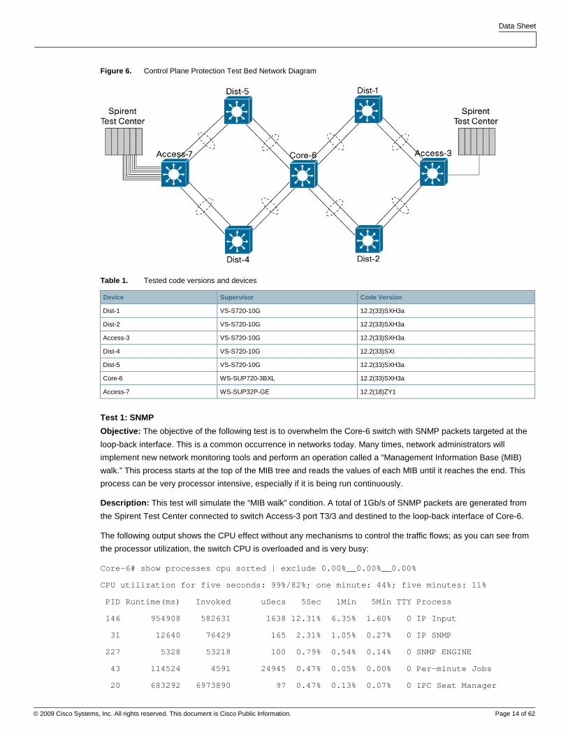
Figure 6. Control Plane Protection Test Bed Network Diagram
Table 1. Tested code versions and devices
Device Supervisor Code Version
Dist-1 VS-S720-10G 12.2(33)SXH3a
Dist-2 VS-S720-10G 12.2(33)SXH3a
Access-3 VS-S720-10G 12.2(33)SXH3a
Dist-4 VS-S720-10G 12.2(33)SXI
Dist-5 VS-S720-10G 12.2(33)SXH3a
Core-6 WS-SUP720-3BXL 12.2(33)SXH3a
Access-7 WS-SUP32P-GE 12.2(18)ZY1
Test 1: SNMP
Objective: The objective of the following test is to overwhelm the Core-6 switch with SNMP packets targeted at the
loop-back interface. This is a common occurrence in networks today. Many times, network administrators will
implement new network monitoring tools and perform an operation called a “Management Information Base (MIB)
walk.” This process starts at the top of the MIB tree and reads the values of each MIB until it reaches the end. This
process can be very processor intensive, especially if it is being run continuously.
Description: This test will simulate the “MIB walk” condition. A total of 1Gb/s of SNMP packets are generated from
the Spirent Test Center connected to switch Access-3 port T3/3 and destined to the loop-back interface of Core-6.
The following output shows the CPU effect without any mechanisms to control the traffic flows; as you can see from
the processor utilization, the switch CPU is overloaded and is very busy:
Core-6# show processes cpu sorted | exclude 0.00%__0.00%__0.00%
CPU utilization for five seconds: 99%/82%; one minute: 44%; five minutes: 11%
PID Runtime(ms) Invoked uSecs 5Sec 1Min 5Min TTY Process
146 954908 582631 1638 12.31% 6.35% 1.60% 0 IP Input
31 12640 76429 165 2.31% 1.05% 0.27% 0 IP SNMP
227 5328 53218 100 0.79% 0.54% 0.14% 0 SNMP ENGINE
43 114524 4591 24945 0.47% 0.05% 0.00% 0 Per-minute Jobs
20 683292 6973890 97 0.47% 0.13% 0.07% 0 IPC Seat Manager
Data Sheet
© 2009 Cisco Systems, Inc. All rights reserved. This document is Cisco Public Information. Page 15 of 62
151 14404 49275 292 0.31% 0.27% 0.07% 0 PDU DISPATCHER
42 28556 269314 106 0.15% 0.03% 0.00% 0 Per-Second Jobs
140 255468 309800 824 0.15% 0.02% 0.00% 0 IP-EIGRP(0): PDM
38 72752 370488 196 0.07% 0.02% 0.00% 0 Net Background
17 732 263610 2 0.07% 0.00% 0.00% 0 IPC Periodic Tim
129 50728 64907046 0 0.07% 0.00% 0.00% 0 Earl NDE Task
292 202208 1183605 170 0.07% 0.07% 0.06% 0 Port manager per
5 692420 48220 14359 0.00% 0.24% 0.19% 0 Check heaps
3 24268 27331 887 0.00% 0.04% 0.00% 0 Exec
139 123064 127479 965 0.00% 0.01% 0.00% 0 CDP Protocol
198 2081944 387189 5377 0.00% 0.02% 0.01% 0 CEF: IPv4 proces
208 38408 131839 291 0.00% 0.01% 0.00% 0 HIDDEN VLAN Proc
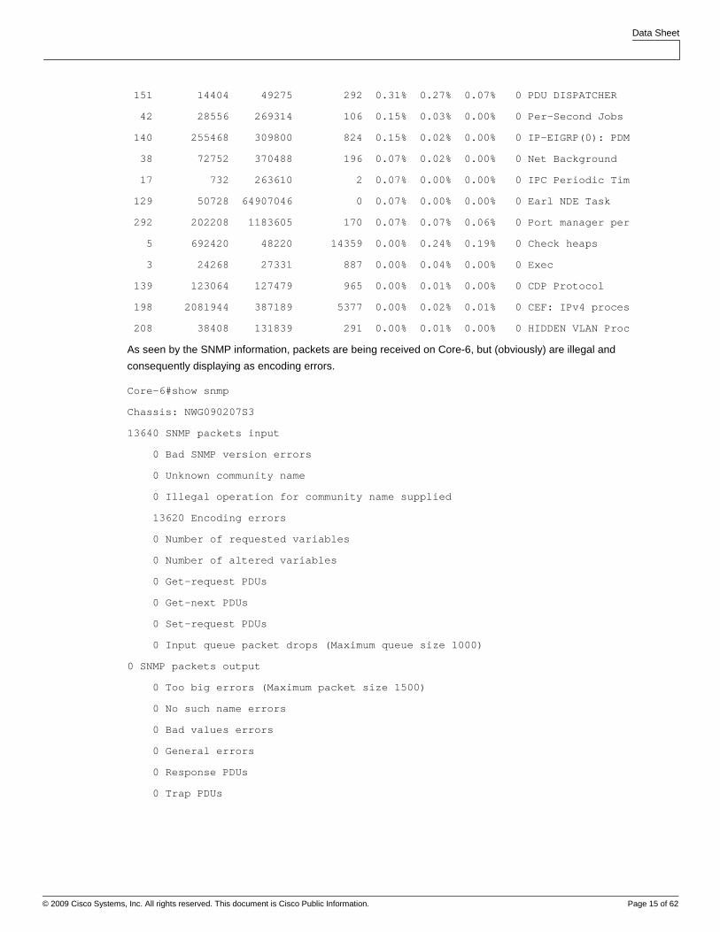
As seen by the SNMP information, packets are being received on Core-6, but (obviously) are illegal and
consequently displaying as encoding errors.
Core-6#show snmp
Chassis: NWG090207S3
13640 SNMP packets input
0 Bad SNMP version errors
0 Unknown community name
0 Illegal operation for community name supplied
13620 Encoding errors
0 Number of requested variables
0 Number of altered variables
0 Get-request PDUs
0 Get-next PDUs
0 Set-request PDUs
0 Input queue packet drops (Maximum queue size 1000)
0 SNMP packets output
0 Too big errors (Maximum packet size 1500)
0 No such name errors
0 Bad values errors
0 General errors
0 Response PDUs
0 Trap PDUs
Data Sheet
© 2009 Cisco Systems, Inc. All rights reserved. This document is Cisco Public Information. Page 16 of 62
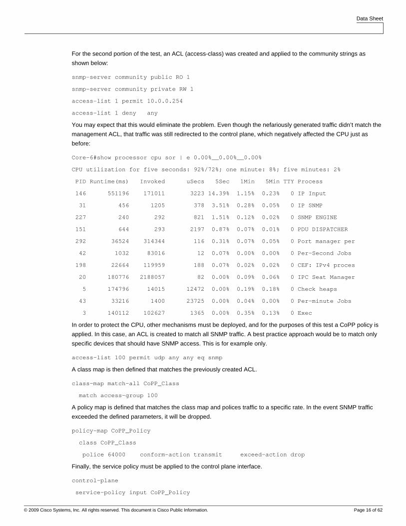
For the second portion of the test, an ACL (access-class) was created and applied to the community strings as
shown below:
snmp-server community public RO 1
snmp-server community private RW 1
access-list 1 permit 10.0.0.254
access-list 1 deny any
You may expect that this would eliminate the problem. Even though the nefariously generated traffic didn’t match the
management ACL, that traffic was still redirected to the control plane, which negatively affected the CPU just as
before:
Core-6#show processor cpu sor | e 0.00%__0.00%__0.00%
CPU utilization for five seconds: 92%/72%; one minute: 8%; five minutes: 2%
PID Runtime(ms) Invoked uSecs 5Sec 1Min 5Min TTY Process
146 551196 171011 3223 14.39% 1.15% 0.23% 0 IP Input
31 456 1205 378 3.51% 0.28% 0.05% 0 IP SNMP
227 240 292 821 1.51% 0.12% 0.02% 0 SNMP ENGINE
151 644 293 2197 0.87% 0.07% 0.01% 0 PDU DISPATCHER
292 36524 314344 116 0.31% 0.07% 0.05% 0 Port manager per
42 1032 83016 12 0.07% 0.00% 0.00% 0 Per-Second Jobs
198 22664 119959 188 0.07% 0.02% 0.02% 0 CEF: IPv4 proces
20 180776 2188057 82 0.00% 0.09% 0.06% 0 IPC Seat Manager
5 174796 14015 12472 0.00% 0.19% 0.18% 0 Check heaps
43 33216 1400 23725 0.00% 0.04% 0.00% 0 Per-minute Jobs
3 140112 102627 1365 0.00% 0.35% 0.13% 0 Exec
In order to protect the CPU, other mechanisms must be deployed, and for the purposes of this test a CoPP policy is
applied. In this case, an ACL is created to match all SNMP traffic. A best practice approach would be to match only
specific devices that should have SNMP access. This is for example only.
access-list 100 permit udp any any eq snmp
A class map is then defined that matches the previously created ACL.
class-map match-all CoPP_Class
match access-group 100
A policy map is defined that matches the class map and polices traffic to a specific rate. In the event SNMP traffic
exceeded the defined parameters, it will be dropped.
policy-map CoPP_Policy
class CoPP_Class
police 64000 conform-action transmit exceed-action drop
Finally, the service policy must be applied to the control plane interface.
control-plane
service-policy input CoPP_Policy
Data Sheet
© 2009 Cisco Systems, Inc. All rights reserved. This document is Cisco Public Information. Page 17 of 62
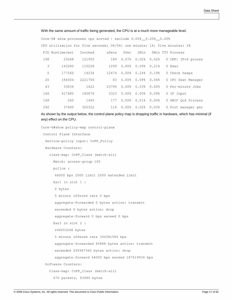
With the same amount of traffic being generated, the CPU is at a much more manageable level.
Core-6# show processes cpu sorted | exclude 0.00%__0.00%__0.00%
CPU utilization for five seconds: 0%/0%; one minute: 1%; five minutes: 2%
PID Runtime(ms) Invoked uSecs 5Sec 1Min 5Min TTY Process
198 23068 121955 189 0.07% 0.02% 0.02% 0 CEF: IPv4 proces
3 143280 110228 1299 0.00% 0.09% 0.21% 0 Exec
5 177560 14234 12474 0.00% 0.24% 0.19% 0 Check heaps
20 184504 2221706 83 0.00% 0.09% 0.06% 0 IPC Seat Manager
43 33836 1422 23794 0.00% 0.03% 0.00% 0 Per-minute Jobs
146 617680 185876 3323 0.00% 0.00% 0.09% 0 IP Input
168 260 1465 177 0.00% 0.01% 0.00% 0 HWIF QoS Process
292 37460 320322 116 0.00% 0.02% 0.03% 0 Port manager per
As shown by the output below, the control plane policy map is dropping traffic in hardware, which has minimal (if
any) effect on the CPU.
Core-6#show policy-map control-plane
Control Plane Interface
Service-policy input: CoPP_Policy
Hardware Counters:
class-map: CoPP_Class (match-all)
Match: access-group 100
police :
64000 bps 2000 limit 2000 extended limit
Earl in slot 1 :
0 bytes
5 minute offered rate 0 bps
aggregate-forwarded 0 bytes action: transmit
exceeded 0 bytes action: drop
aggregate-forward 0 bps exceed 0 bps
Earl in slot 2 :
246053248 bytes
5 minute offered rate 344381584 bps
aggregate-forwarded 85888 bytes action: transmit
exceeded 245967360 bytes action: drop
aggregate-forward 64000 bps exceed 187619936 bps
Software Counters:
Class-map: CoPP_Class (match-all)
670 packets, 83080 bytes
Data Sheet
© 2009 Cisco Systems, Inc. All rights reserved. This document is Cisco Public Information. Page 18 of 62
5 minute offered rate 6000 bps, drop rate 0 bps
Match: access-group 100
police:
cir 64000 bps, bc 2000 bytes
conformed 1131 packets, 140244 bytes; actions:
transmit
exceeded 1 packets, 124 bytes; actions:
drop
conformed 6000 bps, exceed 0 bps
Class-map: class-default (match-any)
113 packets, 15430 bytes
5 minute offered rate 1000 bps, drop rate 0 bps
Match: any
113 packets, 15430 bytes
5 minute rate 1000 bps
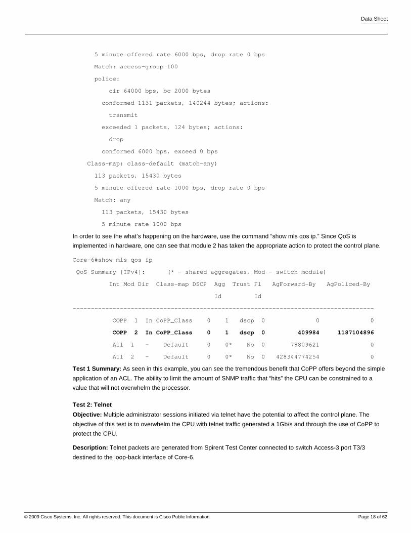
In order to see the what’s happening on the hardware, use the command “show mls qos ip.” Since QoS is
implemented in hardware, one can see that module 2 has taken the appropriate action to protect the control plane.
Core-6#show mls qos ip
QoS Summary [IPv4]: (* - shared aggregates, Mod - switch module)
Int Mod Dir Class-map DSCP Agg Trust Fl AgForward-By AgPoliced-By
Id Id
-----------------------------------------------------------------------------------
COPP 1 In CoPP_Class 0 1 dscp 0 0 0
COPP 2 In CoPP_Class 0 1 dscp 0 409984 1187104896
All 1 - Default 0 0* No 0 78809621 0
All 2 - Default 0 0* No 0 428344774254 0
Test 1 Summary: As seen in this example, you can see the tremendous benefit that CoPP offers beyond the simple
application of an ACL. The ability to limit the amount of SNMP traffic that “hits” the CPU can be constrained to a
value that will not overwhelm the processor.
Test 2: Telnet
Objective: Multiple administrator sessions initiated via telnet have the potential to affect the control plane. The
objective of this test is to overwhelm the CPU with telnet traffic generated a 1Gb/s and through the use of CoPP to
protect the CPU.
Description: Telnet packets are generated from Spirent Test Center connected to switch Access-3 port T3/3
destined to the loop-back interface of Core-6.
Data Sheet
© 2009 Cisco Systems, Inc. All rights reserved. This document is Cisco Public Information. Page 19 of 62
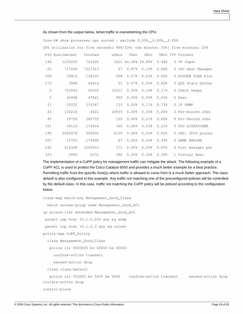
As shown from the output below, telnet traffic is overwhelming the CPU.
Core-6# show processes cpu sorted | exclude 0.00%__0.00%__0.00%
CPU utilization for five seconds: 99%/33%; one minute: 30%; five minutes: 20%
PID Runtime(ms) Invoked uSecs 5Sec 1Min 5Min TTY Process
146 1235200 761605 1621 64.98% 18.88% 5.94% 0 IP Input
20 717248 7327313 97 0.87% 0.15% 0.08% 0 IPC Seat Manager
208 39912 138535 288 0.07% 0.01% 0.00% 0 HIDDEN VLAN Proc
173 3988 64614 61 0.07% 0.00% 0.00% 0 QOS Stats Gather
5 723504 50554 14311 0.00% 0.16% 0.17% 0 Check heaps
3 45868 47821 959 0.00% 0.00% 0.26% 0 Exec
31 29332 219367 133 0.00% 0.11% 0.73% 0 IP SNMP
43 120216 4821 24935 0.00% 0.05% 0.00% 0 Per-minute Jobs
42 29756 282735 105 0.00% 0.01% 0.00% 0 Per-Second Jobs
151 28116 174904 160 0.00% 0.03% 0.21% 0 PDU DISPATCHER
198 2085876 405834 5139 0.00% 0.02% 0.02% 0 CEF: IPv4 proces
227 15700 179498 87 0.00% 0.06% 0.39% 0 SNMP ENGINE
292 214308 1252833 171 0.00% 0.05% 0.05% 0 Port manager per
333 2080 5272 394 0.00% 0.36% 0.30% 1 Virtual Exec
The implementation of a CoPP policy for management traffic can mitigate the attack. The following example of a
CoPP ACL is used to protect the Cisco Catalyst 6500 and provides a much better example for a best practice.
Permitting traffic from the specific host(s) where traffic is allowed to come from is a much better approach. The class
default is also configured in this example. Any traffic not matching one of the preconfigured policies will be controlled
by the default-class. In this case, traffic not matching the CoPP policy will be policed according to the configuration
below.
class-map match-any Management_Good_Class
match access-group name Management_Good_ACL
ip access-list extended Management_Good_ACL
permit udp host 10.1.0.254 any eq snmp
permit tcp host 10.1.0.3 any eq telnet
policy-map CoPP_Policy
class Management_Good_Class
police cir 6000000 bc 60000 be 60000
conform-action transmit
exceed-action drop
class class-default
police cir 500000 bc 5000 be 5000 conform-action transmit exceed-action drop
violate-action drop
control-plane
Data Sheet
© 2009 Cisco Systems, Inc. All rights reserved. This document is Cisco Public Information. Page 20 of 62
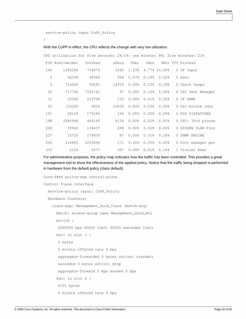
service-policy input CoPP_Policy
!
With the CoPP in effect, the CPU reflects the change with very low utilization.
CPU utilization for five seconds: 2%/1%; one minute: 8%; five minutes: 21%
PID Runtime(ms) Invoked uSecs 5Sec 1Min 5Min TTY Process
146 1285284 774074 1660 1.03% 4.77% 10.00% 0 IP Input
3 46348 48369 958 0.07% 0.19% 0.22% 0 Exec
5 724004 50591 14310 0.00% 0.23% 0.19% 0 Check heaps
20 717740 7332141 97 0.00% 0.10% 0.08% 0 IPC Seat Manager
31 29360 219708 133 0.00% 0.01% 0.35% 0 IP SNMP
43 120292 4824 24936 0.00% 0.03% 0.00% 0 Per-minute Jobs
151 28124 175245 160 0.00% 0.00% 0.09% 0 PDU DISPATCHER
198 2085948 406140 5136 0.00% 0.02% 0.02% 0 CEF: IPv4 proces
208 39960 138637 288 0.00% 0.02% 0.00% 0 HIDDEN VLAN Proc
227 15720 179839 87 0.00% 0.01% 0.18% 0 SNMP ENGINE
292 214452 1253894 171 0.00% 0.05% 0.05% 0 Port manager per
333 2120 5477 387 0.00% 0.01% 0.14% 1 Virtual Exec
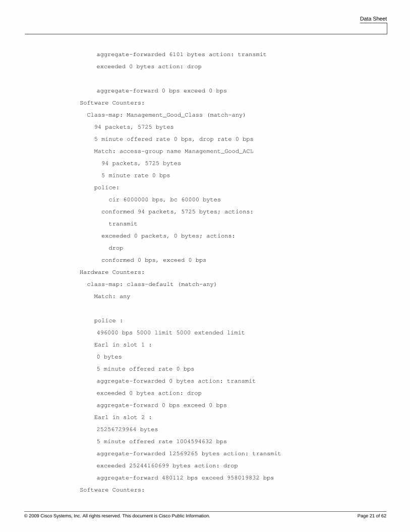
For administrative purposes, the policy map indicates how the traffic has been controlled. This provides a great
management tool to show the effectiveness of the applied policy. Notice that the traffic being dropped is performed
in hardware from the default policy (class default).
Core-6#sh policy-map control-plane
Control Plane Interface
Service-policy input: CoPP_Policy
Hardware Counters:
class-map: Management_Good_Class (match-any)
Match: access-group name Management_Good_ACL
police :
6000000 bps 60000 limit 60000 extended limit
Earl in slot 1 :
0 bytes
5 minute offered rate 0 bps
aggregate-forwarded 0 bytes action: transmit
exceeded 0 bytes action: drop
aggregate-forward 0 bps exceed 0 bps
Earl in slot 2 :
6101 bytes
5 minute offered rate 0 bps
Data Sheet
© 2009 Cisco Systems, Inc. All rights reserved. This document is Cisco Public Information. Page 21 of 62
aggregate-forwarded 6101 bytes action: transmit
exceeded 0 bytes action: drop
aggregate-forward 0 bps exceed 0 bps
Software Counters:
Class-map: Management_Good_Class (match-any)
94 packets, 5725 bytes
5 minute offered rate 0 bps, drop rate 0 bps
Match: access-group name Management_Good_ACL
94 packets, 5725 bytes
5 minute rate 0 bps
police:
cir 6000000 bps, bc 60000 bytes
conformed 94 packets, 5725 bytes; actions:
transmit
exceeded 0 packets, 0 bytes; actions:
drop
conformed 0 bps, exceed 0 bps
Hardware Counters:
class-map: class-default (match-any)
Match: any
police :
496000 bps 5000 limit 5000 extended limit
Earl in slot 1 :
0 bytes
5 minute offered rate 0 bps
aggregate-forwarded 0 bytes action: transmit
exceeded 0 bytes action: drop
aggregate-forward 0 bps exceed 0 bps
Earl in slot 2 :
25256729964 bytes
5 minute offered rate 1004594632 bps
aggregate-forwarded 12569265 bytes action: transmit
exceeded 25244160699 bytes action: drop
aggregate-forward 480112 bps exceed 958019832 bps
Software Counters:
Data Sheet
© 2009 Cisco Systems, Inc. All rights reserved. This document is Cisco Public Information. Page 22 of 62
Class-map: class-default (match-any)
14067 packets, 12685471 bytes
5 minute offered rate 275000 bps, drop rate 0 bps
Match: any
14067 packets, 12685471 bytes
5 minute rate 275000 bps
police:
cir 500000 bps, bc 5000 bytes, be 5000 bytes
conformed 14061 packets, 12734965 bytes; actions:
transmit
exceeded 12 packets, 7292 bytes; actions:
drop
violated 212 packets, 142845 bytes; actions:
drop
conformed 272000 bps, exceed 0 bps, violate 0 bps
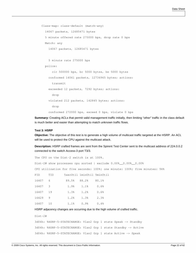
Summary: Creating ACLs that permit valid management traffic initially, then limiting “other” traffic in the class default
is much better and easier than attempting to match unknown traffic flows.
Test 3: HSRP
Objective: The objective of this test is to generate a high volume of multicast traffic targeted at the HSRP. An ACL
will be used to protect the CPU against the multicast attack.
Description: HSRP crafted frames are sent from the Spirent Test Center sent to the multicast address of 224.0.0.2
connected to the switch Access-3 port T3/3.
The CPU on the Dist-2 switch is at 100%.
Dist-2# show processes cpu sorted | exclude 0.00%__0.00%__0.00%
CPU utilization for five seconds: 100%; one minute: 100%; five minutes: 94%
PID TID 5secUtil 1minUtil 5minUtil
16407 6 89.5% 88.2% 80.1%
16407 3 1.9% 1.1% 0.6%
16407 19 1.3% 1.2% 0.6%
16429 9 1.2% 1.3% 2.3%
16407 10 1.1% 0.9% 0.4%
HSRP adjacency changes are occurring due to the high volume of crafted traffic.
Dist-2#
3d04h: %HSRP-5-STATECHANGE: Vlan2 Grp 1 state Speak -> Standby
3d04h: %HSRP-5-STATECHANGE: Vlan2 Grp 1 state Standby -> Active
3d04h: %HSRP-5-STATECHANGE: Vlan2 Grp 1 state Active -> Speak
Data Sheet
© 2009 Cisco Systems, Inc. All rights reserved. This document is Cisco Public Information. Page 23 of 62
3d04h: %HSRP-5-STATECHANGE: Vlan2 Grp 1 state Speak -> Standby
3d04h: %HSRP-5-STATECHANGE: Vlan2 Grp 1 state Standby -> Active
3d04h: %HSRP-5-STATECHANGE: Vlan2 Grp 1 state Active -> Speak
3d04h: %HSRP-5-STATECHANGE: Vlan2 Grp 1 state Speak -> Standby
3d04h: %HSRP-5-STATECHANGE: Vlan2 Grp 1 state Standby -> Active
3d04h: %HSRP-5-STATECHANGE: Vlan2 Grp 1 state Active -> Speak
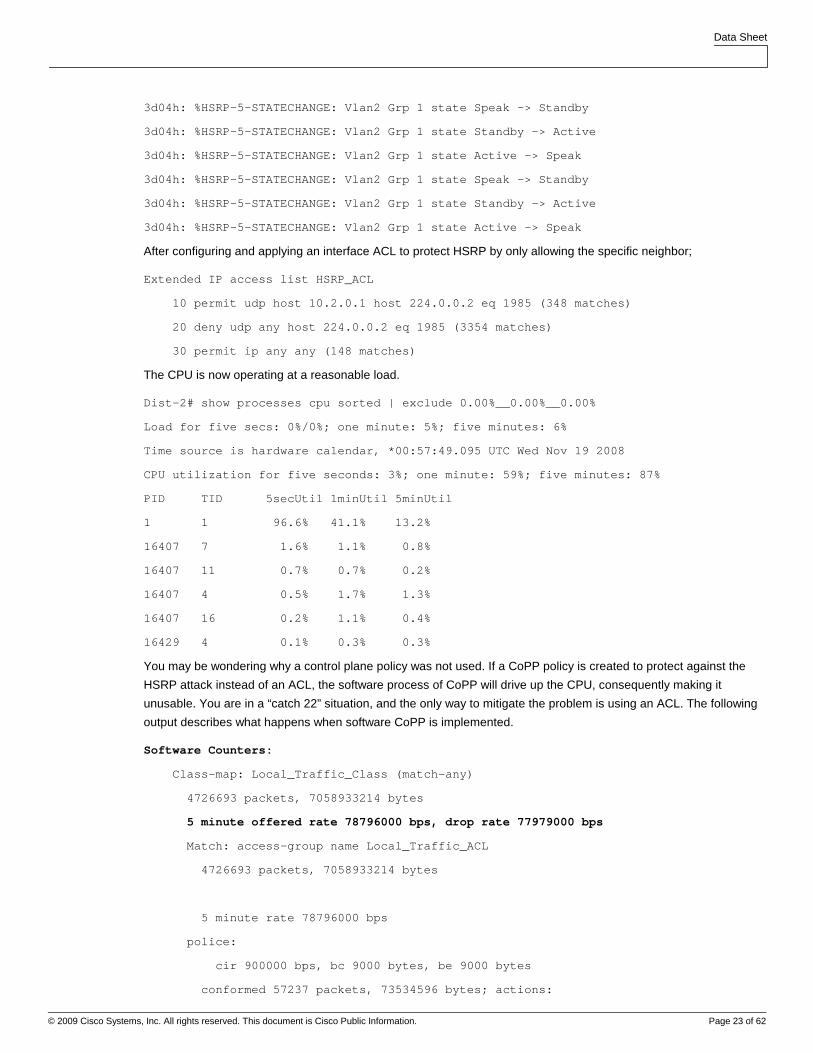
After configuring and applying an interface ACL to protect HSRP by only allowing the specific neighbor;
Extended IP access list HSRP_ACL
10 permit udp host 10.2.0.1 host 224.0.0.2 eq 1985 (348 matches)
20 deny udp any host 224.0.0.2 eq 1985 (3354 matches)
30 permit ip any any (148 matches)
The CPU is now operating at a reasonable load.
Dist-2# show processes cpu sorted | exclude 0.00%__0.00%__0.00%
Load for five secs: 0%/0%; one minute: 5%; five minutes: 6%
Time source is hardware calendar, *00:57:49.095 UTC Wed Nov 19 2008
CPU utilization for five seconds: 3%; one minute: 59%; five minutes: 87%
PID TID 5secUtil 1minUtil 5minUtil
1 1 96.6% 41.1% 13.2%
16407 7 1.6% 1.1% 0.8%
16407 11 0.7% 0.7% 0.2%
16407 4 0.5% 1.7% 1.3%
16407 16 0.2% 1.1% 0.4%
16429 4 0.1% 0.3% 0.3%
You may be wondering why a control plane policy was not used. If a CoPP policy is created to protect against the
HSRP attack instead of an ACL, the software process of CoPP will drive up the CPU, consequently making it
unusable. You are in a “catch 22” situation, and the only way to mitigate the problem is using an ACL. The following
output describes what happens when software CoPP is implemented.
Software Counters:
Class-map: Local_Traffic_Class (match-any)
4726693 packets, 7058933214 bytes
5 minute offered rate 78796000 bps, drop rate 77979000 bps
Match: access-group name Local_Traffic_ACL
4726693 packets, 7058933214 bytes
5 minute rate 78796000 bps
police:
cir 900000 bps, bc 9000 bytes, be 9000 bytes
conformed 57237 packets, 73534596 bytes; actions:
Data Sheet
© 2009 Cisco Systems, Inc. All rights reserved. This document is Cisco Public Information. Page 24 of 62
transmit
exceeded 59 packets, 42374 bytes; actions:
drop
violated 4669321 packets, 6985242548 bytes; actions:
drop
conformed 863000 bps, exceed 1000 bps, violate 77979000 bps
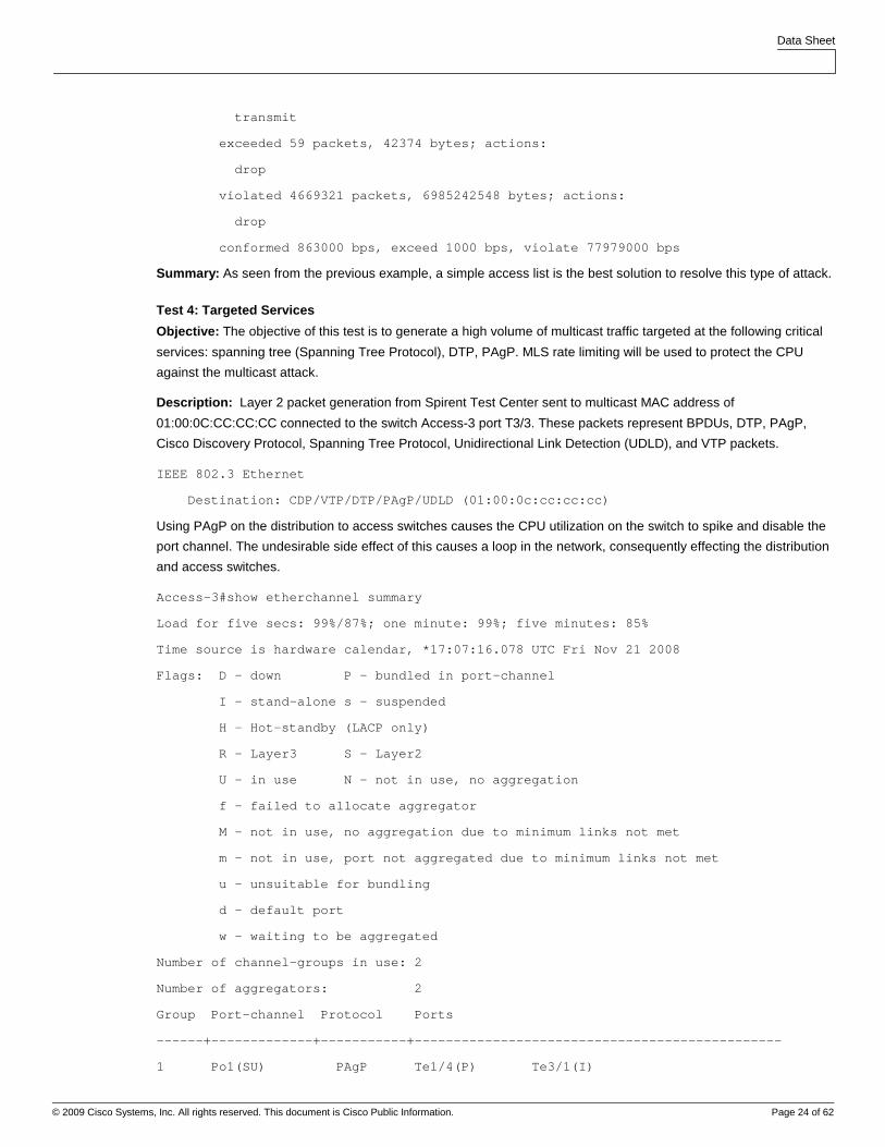
Summary: As seen from the previous example, a simple access list is the best solution to resolve this type of attack.
Test 4: Targeted Services
Objective: The objective of this test is to generate a high volume of multicast traffic targeted at the following critical
services: spanning tree (Spanning Tree Protocol), DTP, PAgP. MLS rate limiting will be used to protect the CPU
against the multicast attack.
Description: Layer 2 packet generation from Spirent Test Center sent to multicast MAC address of
01:00:0C:CC:CC:CC connected to the switch Access-3 port T3/3. These packets represent BPDUs, DTP, PAgP,
Cisco Discovery Protocol, Spanning Tree Protocol, Unidirectional Link Detection (UDLD), and VTP packets.
IEEE 802.3 Ethernet
Destination: CDP/VTP/DTP/PAgP/UDLD (01:00:0c:cc:cc:cc)
Using PAgP on the distribution to access switches causes the CPU utilization on the switch to spike and disable the
port channel. The undesirable side effect of this causes a loop in the network, consequently effecting the distribution
and access switches.
Access-3#show etherchannel summary
Load for five secs: 99%/87%; one minute: 99%; five minutes: 85%
Time source is hardware calendar, *17:07:16.078 UTC Fri Nov 21 2008
Flags: D - down P - bundled in port-channel
I - stand-alone s - suspended
H - Hot-standby (LACP only)
R - Layer3 S - Layer2
U - in use N - not in use, no aggregation
f - failed to allocate aggregator
M - not in use, no aggregation due to minimum links not met
m - not in use, port not aggregated due to minimum links not met
u - unsuitable for bundling
d - default port
w - waiting to be aggregated
Number of channel-groups in use: 2
Number of aggregators: 2
Group Port-channel Protocol Ports
------+-------------+-----------+-----------------------------------------------
1 Po1(SU) PAgP Te1/4(P) Te3/1(I)
Data Sheet
© 2009 Cisco Systems, Inc. All rights reserved. This document is Cisco Public Information. Page 25 of 62
2 Po2(SU) PAgP Te1/5(P) Te3/2(I)
To mitigate the attack, the port channels were reconfigured to “ON” and UDLD was used to prevent a unidirectional
fiber connection. The result was that UDLD was affected and disabled a single port, but a spanning-tree loop was
not created and the CPU of the switch remained low.
Access-3#show etherchannel summary
Load for five secs: 0%/0%; one minute: 1%; five minutes: 1%
Time source is hardware calendar, *17:52:39.842 UTC Fri Nov 21 2008
Flags: D - down P - bundled in port-channel
I - stand-alone s - suspended
H - Hot-standby (LACP only)
R - Layer3 S - Layer2
U - in use N - not in use, no aggregation
f - failed to allocate aggregator
M - not in use, no aggregation due to minimum links not met
m - not in use, port not aggregated due to minimum links not met
u - unsuitable for bundling
d - default port
w - waiting to be aggregated
Number of channel-groups in use: 2
Number of aggregators: 2
Group Port-channel Protocol Ports
------+-------------+-----------+-----------------------------------------------
1 Po1(SU) - Te1/4(P) Te3/1(D)
2 Po2(SU) - Te1/5(P) Te3/2(D)
Summary: Protecting the Cisco Catalyst 6500 is all about using the right tool for the right job. CoPP, HWRL, ACLs,
or other techniques can be used to make sure that your network remains functional under extreme conditions.
Recommended Baseline Configuration for Control Plan e Protection
Ultimately any CoPP based policy is going to be based on the specific traffic profile that is present on a given
network. However, this document will lay out a baseline configuration that can be used as a starting point for
implementing a control plane protection policy. This configuration is set out below, and from this configuration, it can
be refined to suit the needs of the respective network where it is implemented.
In our examples we will be using these addresses:
Cisco Catalyst 6500 Loopback used for Management = 10.0.0.1
Management Station IP Address = 10.1.1.2
TACACS+ Server IP Address = 10.1.1.3
NTP Server IP Address = 10.1.1.4
Network Management Subnet = 10.1.1.0/24
Using an ACL Reverse Mask = 10.1.1.0 0.0.0.255
Data Sheet
© 2009 Cisco Systems, Inc. All rights reserved. This document is Cisco Public Information. Page 26 of 62
Network Administrators VPN Address Range = 10.0.20.0/24
Using an ACL Reverse Mask = 10.0.20.0 0.0.0.255
The baseline configuration is set out below.
conf t
! mls qos must be enabled for Control Plane Policing to Function
mls qos
ip access-list extended acl-CoPP-SNMP
remark allow snmp to the management loopback
permit udp host 10.1.1.2 host 10.0.0.1 eq snmp
remark auto discovery will mean that management has to be reachable via any interface
permit udp host 10.1.1.2 any eq snmp
ip access-list extended acl-CoPP-TerminalSession
remark Will allow terminal sessions only from specific known locations
permit tcp host 10.1.1.2 host 10.0.0.1 eq telnet
permit tcp 10.1.1.0 0.0.0.255 host 10.0.0.1 eq 22
permit tcp 10.0.20.0 0.0.0.255 host 10.0.0.1 eq 22
ip access-list extended acl-CoPP-RoutingProtocol
remark If running iBGP using the Loopback Management Address Range
permit tcp 10.0.0.0 0.0.0.255 host 10.0.0.1 eq bgp
permit tcp 10.0.0.0 0.0.0.255 eq bgp host 10.0.0.1 established
remark If running eBGP you will need to add the neighbors as well
ip access-list extended acl-CoPP-ReturnTraffic
remark used to allow for traffic returning from TACACS+ servers
remark recommendation is to use specific host addresses in order to limit exposure
permit tcp host 10.1.1.3 eq tacacs any established
remark allow ntp packets
permit udp host 10.1.1.4 eq ntp any
permit udp host 10.1.1.4 any eq ntp
ip access-list extended acl-CoPP-GenericSSH
remark will allow ssh access from anywhere to any interface
permit tcp any any eq 22
ip access-list extended acl-CoPP-LocalManagement
remark all responses to device originated traceroute
permit icmp any any ttl-exceeded
permit icmp any any port-unreachable
remark all responses to device originated pings
permit icmp any any echo-reply
Data Sheet
© 2009 Cisco Systems, Inc. All rights reserved. This document is Cisco Public Information. Page 27 of 62
remark allow pings to the device
permit icmp any any echo
ip access-list extended acl-CoPP-Unwanted
remark place permits here for traffic that you do not want reaching the control plane
remark traffic in this acl will be dropped by the policy map
permit udp any any range 135 137
class-map class-CoPP-SNMP
match access-group name acl-CoPP-SNMP
class-map class-CoPP-TerminalSession
match access-group name acl-CoPP-TerminalSession
class-map class-CoPP-RoutingProtocol
match access-group name acl-CoPP-RoutingProtocol
class-map class-CoPP-ReturnTraffic
match access-group name acl-CoPP-ReturnTraffic
class-map class-CoPP-GenericSSH
match access-group name acl-CoPP-GenericSSH
class-map class-CoPP-LocalManagement
match access-group name acl-CoPP-LocalManagement
class-map class-CoPP-Unwanted
match access-group name acl-CoPP-Unwanted
policy-map policy-CoPP
! the order of the class-maps is very important here.
! we need to keep the routing protocol up so that everything is reachable
! we need to keep the AAA server reachable so that terminal session can be
established
! the police rates are very generic, it is very important that you baseline your own
network
! to determine what rate of traffic is absolutely required in order to function
properly
! if you police certain applications at too low of a rate, the application will not
deliver the information
! required. If you police at too high a rate, then you’ve opened your device up to an
avenue of attack.
! remember this is all traffic that will hit the CPU, and impact overall capabilities
to forward traffic.
class class-CoPP-RoutingProtocol
police 512000 conform-action transmit exceed-action drop
class class-CoPP-ReturnTraffic
police 64000 conform-action transmit exceed-action drop
Data Sheet
© 2009 Cisco Systems, Inc. All rights reserved. This document is Cisco Public Information. Page 28 of 62
class class-CoPP-TerminalSession
police 64000 conform-action transmit exceed-action drop
class class-CoPP-SNMP
police 32000 conform-action transmit exceed-action drop
class class-CoPP-GenericSSH
police 32000 conform-action transmit exceed-action drop
class class-CoPP-LocalManagement
police 64000 conform-action transmit exceed-action drop
class class-CoPP-Unwanted
police 32000 conform-action drop exceed-action drop
class class-default
! Generic class for everything else, let’s give it some bandwidth just incase it does
belong
! The 6500 can’t match against multicast traffic, therefore our IGP will fall into
here
! If using ISIS, you will need to create another class prior to this one to rate-
limit IP Traffic
! and use class-default as the catch all for non-IP Traffic
! Tested with 2500 routes, both EIGRP and OSPF. EIGRP required 384k, while OSPF
required 512K.
! Tested with 5000 routes. EIGRP required 1024k, while OSPF required 1152k.
! We still need to leave headroom for other applications that don’t fit into other
buckets
police 1024000 conform-action transmit exceed-action drop
control-plane
service-policy input policy-CoPP
end
Going beyond CoPP on its own, we can use the “mls qos protocol police” command to rate limit specific traffic to a
known rate. The “mls qos protocol” command will police the traffic at Layer 2 as it is input to the Cisco Catalyst 6500.
Therefore, in a large Layer 2 network, with Layer 3 edge interfaces, should the closest link fail between the Layer 3
devices and should the routing protocol traverse the Layer 2 network these commands will still be functional.
conf t
! So to support 2500 routes, we can rate-limit EIGRP to 384K.
! This will happen prior to the control-plane policy. Therefore leaving headroom for
! other protocols in the class-default
mls qos protocol eigrp police 384000
! We can also rate-limit arp traffic
! This will only make it so that the already known information is available under
spanning-tree loops
Data Sheet
© 2009 Cisco Systems, Inc. All rights reserved. This document is Cisco Public Information. Page 29 of 62
! end systems will not be able to find each other as the arp rate-limit won’t allow
them to
! arp for unknown addresses, so other tools such as UDLD and proper network
documentation
! still need to be used
mls qos protocol arp police 2048000
end
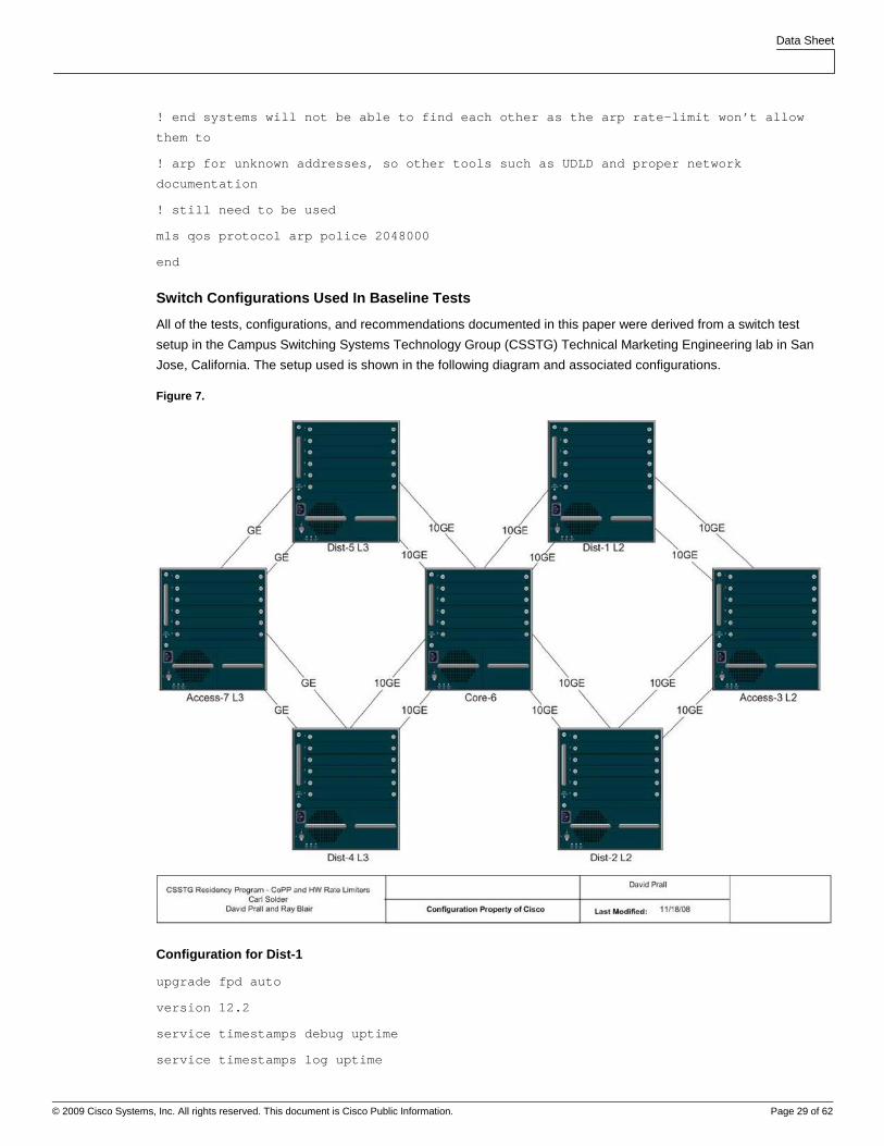
Switch Configurations Used In Baseline Tests
All of the tests, configurations, and recommendations documented in this paper were derived from a switch test
setup in the Campus Switching Systems Technology Group (CSSTG) Technical Marketing Engineering lab in San
Jose, California. The setup used is shown in the following diagram and associated configurations.
Figure 7.
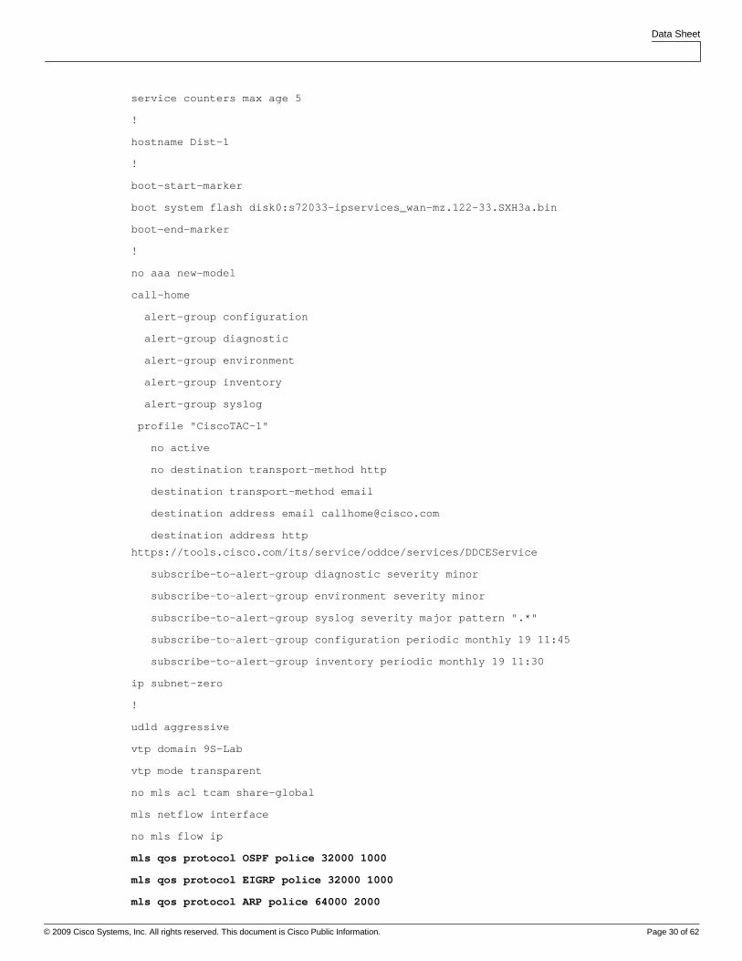
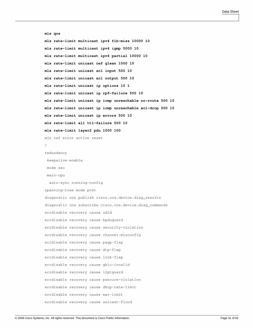
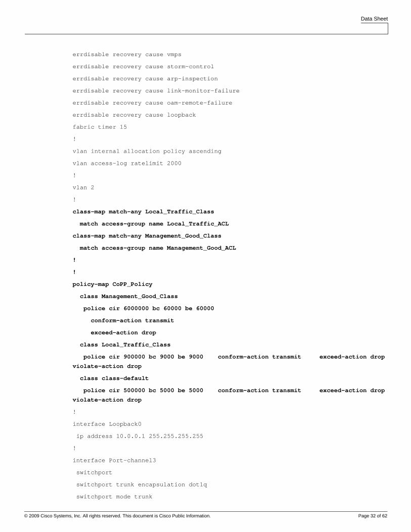
Configuration for Dist-1
upgrade fpd auto
version 12.2
service timestamps debug uptime
service timestamps log uptime
Data Sheet
© 2009 Cisco Systems, Inc. All rights reserved. This document is Cisco Public Information. Page 30 of 62
service counters max age 5
!
hostname Dist-1
!
boot-start-marker
boot system flash disk0:s72033-ipservices_wan-mz.122-33.SXH3a.bin
boot-end-marker
!
no aaa new-model
call-home
alert-group configuration
alert-group diagnostic
alert-group environment
alert-group inventory
alert-group syslog
profile "CiscoTAC-1"
no active
no destination transport-method http
destination transport-method email
destination address email [email protected]
destination address http
https://tools.cisco.com/its/service/oddce/services/DDCEService
subscribe-to-alert-group diagnostic severity minor
subscribe-to-alert-group environment severity minor
subscribe-to-alert-group syslog severity major pattern ".*"
subscribe-to-alert-group configuration periodic monthly 19 11:45
subscribe-to-alert-group inventory periodic monthly 19 11:30
ip subnet-zero
!
udld aggressive
vtp domain 9S-Lab
vtp mode transparent
no mls acl tcam share-global
mls netflow interface
no mls flow ip
mls qos protocol OSPF police 32000 1000
mls qos protocol EIGRP police 32000 1000
mls qos protocol ARP police 64000 2000
Data Sheet
© 2009 Cisco Systems, Inc. All rights reserved. This document is Cisco Public Information. Page 31 of 62
mls qos
mls rate-limit multicast ipv4 fib-miss 10000 10
mls rate-limit multicast ipv4 igmp 5000 10
mls rate-limit multicast ipv4 partial 10000 10
mls rate-limit unicast cef glean 1000 10
mls rate-limit unicast acl input 500 10
mls rate-limit unicast acl output 500 10
mls rate-limit unicast ip options 10 1
mls rate-limit unicast ip rpf-failure 500 10
mls rate-limit unicast ip icmp unreachable no-route 500 10
mls rate-limit unicast ip icmp unreachable acl-drop 500 10
mls rate-limit unicast ip errors 500 10
mls rate-limit all ttl-failure 500 10
mls rate-limit layer2 pdu 1000 100
mls cef error action reset
!
redundancy
keepalive-enable
mode sso
main-cpu
auto-sync running-config
spanning-tree mode pvst
diagnostic cns publish cisco.cns.device.diag_results
diagnostic cns subscribe cisco.cns.device.diag_commands
errdisable recovery cause udld
errdisable recovery cause bpduguard
errdisable recovery cause security-violation
errdisable recovery cause channel-misconfig
errdisable recovery cause pagp-flap
errdisable recovery cause dtp-flap
errdisable recovery cause link-flap
errdisable recovery cause gbic-invalid
errdisable recovery cause l2ptguard
errdisable recovery cause psecure-violation
errdisable recovery cause dhcp-rate-limit
errdisable recovery cause mac-limit
errdisable recovery cause unicast-flood
Data Sheet
© 2009 Cisco Systems, Inc. All rights reserved. This document is Cisco Public Information. Page 32 of 62
errdisable recovery cause vmps
errdisable recovery cause storm-control
errdisable recovery cause arp-inspection
errdisable recovery cause link-monitor-failure
errdisable recovery cause oam-remote-failure
errdisable recovery cause loopback
fabric timer 15
!
vlan internal allocation policy ascending
vlan access-log ratelimit 2000
!
vlan 2
!
class-map match-any Local_Traffic_Class
match access-group name Local_Traffic_ACL
class-map match-any Management_Good_Class
match access-group name Management_Good_ACL
!
!
policy-map CoPP_Policy
class Management_Good_Class
police cir 6000000 bc 60000 be 60000
conform-action transmit
exceed-action drop
class Local_Traffic_Class
police cir 900000 bc 9000 be 9000 conform-action transmit exceed-action drop
violate-action drop
class class-default
police cir 500000 bc 5000 be 5000 conform-action transmit exceed-action drop
violate-action drop
!
interface Loopback0
ip address 10.0.0.1 255.255.255.255
!
interface Port-channel3
switchport
switchport trunk encapsulation dot1q
switchport mode trunk
Data Sheet
© 2009 Cisco Systems, Inc. All rights reserved. This document is Cisco Public Information. Page 33 of 62
no mls qos channel-consistency
!
interface Port-channel6
switchport
switchport trunk encapsulation dot1q
switchport mode trunk
no mls qos channel-consistency
!
interface GigabitEthernet5/3
no ip address
!
interface TenGigabitEthernet5/4
switchport
switchport trunk encapsulation dot1q
switchport mode trunk
channel-group 3 mode desirable non-silent
!
interface TenGigabitEthernet5/5
switchport
switchport trunk encapsulation dot1q
switchport mode trunk
channel-group 6 mode desirable
!
interface TenGigabitEthernet8/1
switchport
switchport trunk encapsulation dot1q
switchport mode trunk
channel-group 3 mode desirable non-silent
!
interface TenGigabitEthernet8/2
switchport
switchport trunk encapsulation dot1q
switchport mode trunk
channel-group 6 mode desirable
!
interface TenGigabitEthernet8/3
no ip address
Data Sheet
© 2009 Cisco Systems, Inc. All rights reserved. This document is Cisco Public Information. Page 34 of 62
!
interface TenGigabitEthernet8/4
no ip address
!
interface TenGigabitEthernet8/5
no ip address
!
interface TenGigabitEthernet8/6
no ip address
!
interface TenGigabitEthernet8/7
no ip address
!
interface TenGigabitEthernet8/8
no ip address
!
interface Vlan1
ip address 10.1.0.1 255.255.0.0
no ip redirects
no ip unreachables
!
interface Vlan2
ip address 10.2.0.1 255.255.255.0
ip access-group HSRP_ACL in
standby 1 ip 10.2.0.254
standby 1 timers 1 3
standby 1 priority 110
standby 1 preempt
!
router eigrp 1
network 0.0.0.0
no auto-summary
!
ip classless
ip route 0.0.0.0 0.0.0.0 10.1.0.6
!
no ip http server
Data Sheet
© 2009 Cisco Systems, Inc. All rights reserved. This document is Cisco Public Information. Page 35 of 62
!
ip access-list extended HSRP_ACL
permit udp host 10.2.0.2 host 224.0.0.2 eq 1985
deny udp any host 224.0.0.2 eq 1985
permit ip any any
ip access-list extended Local_Traffic_ACL
permit udp host 0.0.0.0 host 255.255.255.255 eq bootps
permit udp host 10.254.254.254 eq bootps any eq bootps
ip access-list extended Management_Good_ACL
permit udp host 10.1.0.254 any eq snmp
permit tcp host 10.1.0.3 any eq telnet
permit tcp host 10.1.0.3 any eq 22
permit udp host 10.200.200.200 any eq ntp
!
access-list 1 permit 10.0.0.254
access-list 1 deny any
snmp-server community public RO 1
snmp-server community private RW 1
!
control-plane
service-policy input CoPP_Policy
!
dial-peer cor custom
!
line con 0
logging synchronous
line vty 0 4
transport input lat pad udptn telnet rlogin
line vty 5 15
transport input lat pad udptn telnet rlogin
!
monitor session 1 type local
source cpu rp
destination interface Gi5/3
!
Data Sheet
© 2009 Cisco Systems, Inc. All rights reserved. This document is Cisco Public Information. Page 36 of 62
mac-address-table aging-time 480
!
end
Configuration for Dist-2
upgrade fpd auto
version 12.2
service timestamps debug uptime
service timestamps log uptime
service counters max age 5
!
hostname Dist-2
!
boot-start-marker
boot system sup-bootdisk:s72033-adventerprisek9_wan_dbg-vz.SIERRA_INTEG_070730
boot-end-marker
!
no aaa new-model
ip subnet-zero
!
no ip domain-lookup
!
vtp domain 9S-Lab
vtp mode transparent
udld aggressive
call-home
alert-group configuration
alert-group diagnostic
alert-group environment
alert-group inventory
alert-group syslog
profile "CiscoTAC-1"
no active
no destination transport-method http
destination transport-method email
destination address email [email protected]
destination address http
https://tools.cisco.com/its/service/oddce/services/DDCEService
Data Sheet
© 2009 Cisco Systems, Inc. All rights reserved. This document is Cisco Public Information. Page 37 of 62
subscribe-to-alert-group diagnostic severity minor
subscribe-to-alert-group environment severity minor
subscribe-to-alert-group syslog severity major pattern ".*"
subscribe-to-alert-group configuration periodic monthly 2 10:28
subscribe-to-alert-group inventory periodic monthly 2 10:13
mls netflow interface
no mls flow ip
no mls flow ipv6
mls qos protocol OSPF police 32000 1000
mls qos protocol EIGRP police 32000 1000
mls qos protocol ARP police 64000 2000
mls qos
mls rate-limit multicast ipv4 fib-miss 10000 10
mls rate-limit multicast ipv4 igmp 5000 10
mls rate-limit multicast ipv4 partial 10000 10
mls rate-limit unicast cef glean 1000 10
mls rate-limit unicast acl input 500 10
mls rate-limit unicast acl output 500 10
mls rate-limit unicast ip options 10 1
mls rate-limit unicast ip rpf-failure 500 10
mls rate-limit unicast ip icmp unreachable no-route 500 10
mls rate-limit unicast ip icmp unreachable acl-drop 500 10
mls rate-limit unicast ip errors 500 10
mls rate-limit all ttl-failure 500 10
mls rate-limit layer2 pdu 1000 100
no mls acl tcam share-global
mls cef error action reset
!
diagnostic cns publish cisco.cns.device.diag_results
diagnostic cns subscribe cisco.cns.device.diag_commands
!
redundancy
keepalive-enable
mode sso
main-cpu
auto-sync running-config
spanning-tree mode pvst
Data Sheet
© 2009 Cisco Systems, Inc. All rights reserved. This document is Cisco Public Information. Page 38 of 62
!
vlan internal allocation policy ascending
vlan access-log ratelimit 2000
!
vlan 2
!
class-map match-any Local_Traffic_Class
match access-group name Local_Traffic_ACL
class-map match-any Management_Good_Class
match access-group name Management_Good_ACL
!
policy-map CoPP_Policy
class Management_Good_Class
police cir 6000000 bc 60000 be 60000
conform-action transmit
exceed-action drop
class Local_Traffic_Class
police cir 900000 bc 9000 be 9000 conform-action transmit exceed-action drop
violate-action drop
class class-default
police cir 500000 bc 5000 be 5000 conform-action transmit exceed-action drop
violate-action drop
!
interface Loopback0
ip address 10.0.0.2 255.255.255.255
!
interface Port-channel3
switchport
switchport trunk encapsulation dot1q
switchport mode trunk
no mls qos channel-consistency
!
interface Port-channel6
switchport
switchport trunk encapsulation dot1q
switchport mode trunk
no mls qos channel-consistency
!
Data Sheet
© 2009 Cisco Systems, Inc. All rights reserved. This document is Cisco Public Information. Page 39 of 62
interface TenGigabitEthernet3/1
switchport
switchport trunk encapsulation dot1q
switchport mode trunk
channel-group 3 mode desirable non-silent
!
interface TenGigabitEthernet3/2
switchport
switchport trunk encapsulation dot1q
switchport mode trunk
channel-group 6 mode desirable
!
interface TenGigabitEthernet3/3
no ip address
!
interface TenGigabitEthernet3/4
no ip address
!
interface TenGigabitEthernet3/5
no ip address
!
interface TenGigabitEthernet3/6
no ip address
!
interface TenGigabitEthernet3/7
no ip address
!
interface TenGigabitEthernet3/8
no ip address
!
interface TenGigabitEthernet5/4
switchport
switchport trunk encapsulation dot1q
switchport mode trunk
channel-group 3 mode desirable non-silent
!
interface TenGigabitEthernet5/5
Data Sheet
© 2009 Cisco Systems, Inc. All rights reserved. This document is Cisco Public Information. Page 40 of 62
switchport
switchport trunk encapsulation dot1q
switchport mode trunk
channel-group 6 mode desirable
!
interface Vlan1
ip address 10.1.0.2 255.255.0.0
no ip redirects
no ip unreachables
no mop enabled
!
interface Vlan2
ip address 10.2.0.2 255.255.255.0
ip access-group HSRP_ACL in
standby 1 ip 10.2.0.254
standby 1 timers 1 3
standby 1 preempt
no mop enabled
!
router eigrp 1
network 0.0.0.0
no auto-summary
!
ip classless
ip route 0.0.0.0 0.0.0.0 10.1.0.6
!
no ip http server
no ip http secure-server
!
ip access-list extended HSRP_ACL
permit udp host 10.2.0.1 host 224.0.0.2 eq 1985
deny udp any host 224.0.0.2 eq 1985
permit ip any any
ip access-list extended Local_Traffic_ACL
permit udp host 0.0.0.0 host 255.255.255.255 eq bootps
permit udp host 10.254.254.254 eq bootps any eq bootps
ip access-list extended Management_Good_ACL
Data Sheet
© 2009 Cisco Systems, Inc. All rights reserved. This document is Cisco Public Information. Page 41 of 62
permit udp host 10.1.0.254 any eq snmp
permit tcp host 10.1.0.3 any eq telnet
permit tcp host 10.1.0.3 any eq 22
permit udp host 10.200.200.200 any eq ntp
access-list 1 permit 10.0.0.254
access-list 1 deny any
!
snmp-server community public RO 1
snmp-server community private RW 1
!
control-plane
service-policy input CoPP_Policy
!
dial-peer cor custom
!
line con 0
logging synchronous
line vty 0 4
transport input lat pad udptn telnet rlogin mop ssh nasi acercon
line vty 5 15
transport input lat pad udptn telnet rlogin mop ssh nasi acercon
!
end
Configuration for Access-3
upgrade fpd auto
version 12.2
service timestamps debug uptime
service timestamps log uptime
service counters max age 5
!
hostname Access-3
!
boot-start-marker
boot system flash disk0:s72033-ipservices_wan-mz.122-33.SXH3a.bin
boot-end-marker
!
no aaa new-model
Data Sheet
© 2009 Cisco Systems, Inc. All rights reserved. This document is Cisco Public Information. Page 42 of 62
call-home
alert-group configuration
alert-group diagnostic
alert-group environment
alert-group inventory
alert-group syslog
profile "CiscoTAC-1"
no active
no destination transport-method http
destination transport-method email
destination address email [email protected]
destination address http
https://tools.cisco.com/its/service/oddce/services/DDCEService
subscribe-to-alert-group diagnostic severity minor
subscribe-to-alert-group environment severity minor
subscribe-to-alert-group syslog severity major pattern ".*"
subscribe-to-alert-group configuration periodic monthly 1 13:55
subscribe-to-alert-group inventory periodic monthly 1 13:40
ip subnet-zero
!
no ip domain-lookup
udld aggressive
vtp domain 9S-Lab
vtp mode transparent
no mls acl tcam share-global
mls netflow interface
no mls flow ip
mls qos protocol OSPF police 32000 1000
mls qos protocol EIGRP police 32000 1000
mls qos protocol ARP police 64000 2000
mls qos
mls rate-limit multicast ipv4 fib-miss 10000 10
mls rate-limit multicast ipv4 igmp 5000 10
mls rate-limit multicast ipv4 partial 10000 10
mls rate-limit unicast cef glean 1000 10
mls rate-limit unicast acl input 500 10
mls rate-limit unicast acl output 500 10
mls rate-limit unicast ip rpf-failure 500 10
Data Sheet
© 2009 Cisco Systems, Inc. All rights reserved. This document is Cisco Public Information. Page 43 of 62
mls rate-limit unicast ip icmp unreachable no-route 500 10
mls rate-limit unicast ip icmp unreachable acl-drop 500 10
mls rate-limit unicast ip errors 500 10
mls rate-limit all ttl-failure 500 10
mls rate-limit layer2 pdu 1000 100
mls cef error action reset
!
redundancy
keepalive-enable
mode sso
main-cpu
auto-sync running-config
spanning-tree mode pvst
spanning-tree extend system-id
diagnostic cns publish cisco.cns.device.diag_results
diagnostic cns subscribe cisco.cns.device.diag_commands
errdisable recovery cause udld
errdisable recovery cause bpduguard
errdisable recovery cause security-violation
errdisable recovery cause channel-misconfig
errdisable recovery cause pagp-flap
errdisable recovery cause dtp-flap
errdisable recovery cause link-flap
errdisable recovery cause gbic-invalid
errdisable recovery cause l2ptguard
errdisable recovery cause psecure-violation
errdisable recovery cause dhcp-rate-limit
errdisable recovery cause mac-limit
errdisable recovery cause unicast-flood
errdisable recovery cause vmps
errdisable recovery cause storm-control
errdisable recovery cause arp-inspection
errdisable recovery cause link-monitor-failure
errdisable recovery cause oam-remote-failure
errdisable recovery cause loopback
fabric timer 15
fabric switching-mode allow truncated threshold 1
Data Sheet
© 2009 Cisco Systems, Inc. All rights reserved. This document is Cisco Public Information. Page 44 of 62
fabric switching-mode allow truncated
!
vlan internal allocation policy ascending
vlan access-log ratelimit 2000
!
vlan 2
!
interface Loopback0
ip address 10.0.0.3 255.255.255.255
!
interface Port-channel1
switchport
switchport trunk encapsulation dot1q
switchport mode trunk
no mls qos channel-consistency
!
interface Port-channel2
switchport
switchport trunk encapsulation dot1q
switchport mode trunk
no mls qos channel-consistency
!
interface GigabitEthernet1/3
no ip address
!
interface TenGigabitEthernet1/4
switchport
switchport trunk encapsulation dot1q
switchport mode trunk
channel-group 1 mode desirable non-silent
!
interface TenGigabitEthernet1/5
switchport
switchport trunk encapsulation dot1q
switchport mode trunk
channel-group 2 mode desirable non-silent
!
Data Sheet
© 2009 Cisco Systems, Inc. All rights reserved. This document is Cisco Public Information. Page 45 of 62
interface TenGigabitEthernet3/1
switchport
switchport mode trunk
channel-group 1 mode desirable non-silent
!
interface TenGigabitEthernet3/2
switchport
switchport mode trunk
udld port aggressive
channel-group 2 mode desirable non-silent
!
interface TenGigabitEthernet3/3
switchport
switchport access vlan 2
switchport mode access
!
interface Vlan1
ip address 10.1.0.3 255.255.0.0
no ip redirects
no ip unreachables
!
interface Vlan2
ip address 10.2.0.3 255.255.255.0
!
ip classless
ip route 0.0.0.0 0.0.0.0 10.1.0.6
!
no ip http server
!
control-plane
!
dial-peer cor custom
!
line con 0
logging synchronous
line vty 0 4
transport input lat pad udptn telnet rlogin
Data Sheet
© 2009 Cisco Systems, Inc. All rights reserved. This document is Cisco Public Information. Page 46 of 62
line vty 5 15
transport input lat pad udptn telnet rlogin
!
monitor session 1 type local
source cpu rp
destination interface Gi1/3
!
end
Configuration for Dist-4
upgrade fpd auto
version 12.2
service timestamps debug uptime
service timestamps log uptime
service counters max age 5
!
hostname Dist-4
!
boot-start-marker
boot system flash disk0:s72033-ipservices_wan-mz.122-33.SXI.bin
boot-end-marker
!
no aaa new-model
ip subnet-zero
!
no ip domain-lookup
mls ip slb purge global
no mls acl tcam share-global
mls netflow interface
no mls flow ip
no mls flow ipv6
mls qos protocol ARP police 64000 2000
mls qos
mls rate-limit multicast ipv4 fib-miss 10000 10
mls rate-limit multicast ipv4 igmp 5000 10
mls rate-limit multicast ipv4 partial 10000 10
mls rate-limit unicast cef glean 1000 10
mls rate-limit unicast acl input 500 10
Data Sheet
© 2009 Cisco Systems, Inc. All rights reserved. This document is Cisco Public Information. Page 47 of 62
mls rate-limit unicast acl output 500 10
mls rate-limit unicast ip rpf-failure 500 10
mls rate-limit unicast ip icmp unreachable no-route 500 10
mls rate-limit unicast ip icmp unreachable acl-drop 500 10
mls rate-limit unicast ip errors 500 10
mls rate-limit all ttl-failure 500 10
mls rate-limit layer2 pdu 1000 100
mls cef error action reset
!
spanning-tree mode pvst
spanning-tree extend system-id
diagnostic bootup level minimal
diagnostic cns publish cisco.cns.device.diag_results
diagnostic cns subscribe cisco.cns.device.diag_commands
fabric timer 15
!
redundancy
main-cpu
auto-sync running-config
mode sso
!
vlan internal allocation policy ascending
vlan access-log ratelimit 2000
!
interface Loopback0
ip address 10.0.0.4 255.255.255.0
!
interface Port-channel6
ip address 10.0.46.4 255.255.255.0
no ip redirects
no ip unreachables
!
interface Port-channel7
ip address 10.0.47.4 255.255.255.0
no ip redirects
no ip unreachables
!
Data Sheet
© 2009 Cisco Systems, Inc. All rights reserved. This document is Cisco Public Information. Page 48 of 62
router eigrp 1
network 0.0.0.0
no auto-summary
!
ip classless
!
no ip http server
!
control-plane
!
dial-peer cor custom
!
line con 0
logging synchronous
line vty 0 4
transport input lat pad udptn telnet rlogin
line vty 5 15
transport input lat pad udptn telnet rlogin
!
monitor session 2 type local
shutdown
source cpu rp
!
end
Configuration for Dist-5
upgrade fpd auto
version 12.2
service timestamps debug uptime
service timestamps log uptime
service counters max age 5
!
hostname Dist-5
!
boot-start-marker
boot-end-marker
!
no aaa new-model
Data Sheet
© 2009 Cisco Systems, Inc. All rights reserved. This document is Cisco Public Information. Page 49 of 62
ip subnet-zero
!
vtp domain 100
vtp mode transparent
call-home
alert-group configuration
alert-group diagnostic
alert-group environment
alert-group inventory
alert-group syslog
profile "CiscoTAC-1"
no active
no destination transport-method http
destination transport-method email
destination address email [email protected]
destination address http
https://tools.cisco.com/its/service/oddce/services/DDCEService
subscribe-to-alert-group diagnostic severity minor
subscribe-to-alert-group environment severity minor
subscribe-to-alert-group syslog severity major pattern ".*"
subscribe-to-alert-group configuration periodic monthly 5 13:31
subscribe-to-alert-group inventory periodic monthly 5 13:16
mls netflow interface
no mls flow ip
no mls flow ipv6
mls qos protocol ARP police 64000 2000
mls qos
mls rate-limit multicast ipv4 fib-miss 10000 10
mls rate-limit multicast ipv4 igmp 5000 10
mls rate-limit multicast ipv4 partial 10000 10
mls rate-limit unicast cef glean 1000 10
mls rate-limit unicast acl input 500 10
mls rate-limit unicast acl output 500 10
mls rate-limit unicast ip rpf-failure 500 10
mls rate-limit unicast ip icmp unreachable no-route 500 10
mls rate-limit unicast ip icmp unreachable acl-drop 500 10
mls rate-limit unicast ip errors 500 10
mls rate-limit all ttl-failure 500 10
Data Sheet
© 2009 Cisco Systems, Inc. All rights reserved. This document is Cisco Public Information. Page 50 of 62
mls rate-limit layer2 pdu 1000 100
no mls acl tcam share-global
mls cef error action reset
!
fabric switching-mode allow truncated threshold 1
fabric switching-mode allow truncated
diagnostic cns publish cisco.cns.device.diag_results
diagnostic cns subscribe cisco.cns.device.diag_commands
!
redundancy
keepalive-enable
mode sso
main-cpu
auto-sync running-config
spanning-tree mode pvst
spanning-tree extend system-id
!
vlan internal allocation policy ascending
vlan access-log ratelimit 2000
!
vlan 2
name **192.168.146.0/24**
!
vlan 3
name **192.168.147.0/26**
!
vlan 4
name *192.168.147.64/27*
!
vlan 5
name *10.253.7.0/24*
!
vlan 6
name *192.168.147.128/26*
!
vlan 7
name *192.168.147.192/26*
Data Sheet
© 2009 Cisco Systems, Inc. All rights reserved. This document is Cisco Public Information. Page 51 of 62
!
vlan 102
name *DHCP/DNS_Heartbeat*
!
interface Loopback0
ip address 10.0.0.5 255.255.255.0
!
interface Port-channel6
ip address 10.0.56.5 255.255.255.0
no ip redirects
no ip unreachables
!
interface Port-channel7
ip address 10.0.57.5 255.255.255.0
no ip redirects
no ip unreachables
!
interface TenGigabitEthernet1/4
no ip address
channel-group 6 mode active
!
interface TenGigabitEthernet1/5
no ip address
channel-group 6 mode active
!
interface GigabitEthernet2/1
no ip address
channel-group 7 mode active
!
interface GigabitEthernet2/2
no ip address
channel-group 7 mode active
!
router eigrp 1
network 0.0.0.0
no auto-summary
!
Data Sheet
© 2009 Cisco Systems, Inc. All rights reserved. This document is Cisco Public Information. Page 52 of 62
ip classless
!
no ip http server
no ip http secure-server
!
control-plane
!
dial-peer cor custom
!
line con 0
logging synchronous
line vty 0 4
transport input lat pad udptn telnet rlogin mop ssh nasi acercon
line vty 5 15
transport input lat pad udptn telnet rlogin mop ssh nasi acercon
!
end
Configuration for Core-6
upgrade fpd auto
version 12.2
service timestamps debug uptime
service timestamps log uptime
service counters max age 5
!
hostname Core-6
!
boot-start-marker
boot-end-marker
!
no aaa new-model
call-home
alert-group configuration
alert-group diagnostic
alert-group environment
alert-group inventory
alert-group syslog
profile "CiscoTAC-1"
Data Sheet
© 2009 Cisco Systems, Inc. All rights reserved. This document is Cisco Public Information. Page 53 of 62
no active
no destination transport-method http
destination transport-method email
destination address email [email protected]
destination address http
https://tools.cisco.com/its/service/oddce/services/DDCEService
subscribe-to-alert-group diagnostic severity minor
subscribe-to-alert-group environment severity minor
subscribe-to-alert-group syslog severity major pattern ".*"
subscribe-to-alert-group configuration periodic monthly 5 13:31
subscribe-to-alert-group inventory periodic monthly 5 13:16
ip subnet-zero
!
vtp mode transparent
no mls acl tcam share-global
mls netflow interface
no mls flow ip
mls qos protocol ARP police 64000 2000
mls qos
mls rate-limit multicast ipv4 fib-miss 10000 10
mls rate-limit multicast ipv4 igmp 5000 10
mls rate-limit multicast ipv4 partial 10000 10
mls rate-limit unicast cef glean 1000 10
mls rate-limit unicast acl input 500 10
mls rate-limit unicast acl output 500 10
mls rate-limit unicast ip options 10 1
mls rate-limit unicast ip rpf-failure 500 10
mls rate-limit unicast ip icmp unreachable no-route 500 10
mls rate-limit unicast ip icmp unreachable acl-drop 500 10
mls rate-limit unicast ip errors 500 10
mls rate-limit all ttl-failure 500 10
mls rate-limit layer2 pdu 1000 100
mls cef error action reset
!
redundancy
keepalive-enable
mode sso
main-cpu
Data Sheet
© 2009 Cisco Systems, Inc. All rights reserved. This document is Cisco Public Information. Page 54 of 62
auto-sync running-config
!
spanning-tree mode pvst
spanning-tree extend system-id
spanning-tree vlan 1 priority 4096
diagnostic cns publish cisco.cns.device.diag_results
diagnostic cns subscribe cisco.cns.device.diag_commands
fabric timer 15
!
vlan internal allocation policy ascending
vlan access-log ratelimit 2000
!
class-map match-any Local_Traffic_Class
match access-group name Local_Traffic_ACL
class-map match-any Management_Good_Class
match access-group name Management_Good_ACL
!
policy-map CoPP_Policy
class Management_Good_Class
police cir 6000000 bc 60000 be 60000
conform-action transmit
exceed-action drop
class Local_Traffic_Class
police cir 900000 bc 9000 be 9000 conform-action transmit exceed-action drop
violate-action drop
class class-default
police cir 500000 bc 5000 be 5000 conform-action transmit exceed-action drop
violate-action drop
!
interface Loopback0
ip address 10.0.0.6 255.255.255.255
!
interface Port-channel1
switchport
switchport trunk encapsulation dot1q
switchport mode trunk
load-interval 30
!
Data Sheet
© 2009 Cisco Systems, Inc. All rights reserved. This document is Cisco Public Information. Page 55 of 62
interface Port-channel2
switchport
switchport trunk encapsulation dot1q
switchport mode trunk
load-interval 30
!
interface Port-channel4
ip address 10.0.46.6 255.255.255.0
no ip redirects
no ip unreachables
!
interface Port-channel5
ip address 10.0.56.6 255.255.255.0
no ip redirects
no ip unreachables
!
interface TenGigabitEthernet2/1
switchport
switchport mode trunk
load-interval 30
channel-group 1 mode desirable
!
interface TenGigabitEthernet2/3
switchport
switchport mode trunk
load-interval 30
channel-group 1 mode desirable
!
interface TenGigabitEthernet2/5
switchport
switchport mode trunk
load-interval 30
channel-group 2 mode desirable
!
interface TenGigabitEthernet2/7
switchport
switchport mode trunk
Data Sheet
© 2009 Cisco Systems, Inc. All rights reserved. This document is Cisco Public Information. Page 56 of 62
load-interval 30
channel-group 2 mode desirable
!
interface TenGigabitEthernet2/9
no ip address
load-interval 30
channel-group 4 mode active
!
interface TenGigabitEthernet2/11
no ip address
load-interval 30
channel-group 4 mode active
!
interface TenGigabitEthernet2/13
no ip address
load-interval 30
channel-group 5 mode active
!
interface TenGigabitEthernet2/15
no ip address
load-interval 30
channel-group 5 mode active
!
interface Vlan1
ip address 10.1.0.6 255.255.0.0
no ip redirects
no ip unreachables
!
router eigrp 1
network 0.0.0.0
no auto-summary
!
router ospf 1
log-adjacency-changes
network 0.0.0.0 255.255.255.255 area 0
!
ip classless
Data Sheet
© 2009 Cisco Systems, Inc. All rights reserved. This document is Cisco Public Information. Page 57 of 62
ip route 0.0.0.0 0.0.0.0 Null0
!
no ip http server
!
ip access-list extended Local_Traffic_ACL
permit ip any host 224.0.0.2
permit udp host 0.0.0.0 host 255.255.255.255 eq bootps
permit udp host 10.254.254.254 eq bootps any eq bootps
ip access-list extended Management_Good_ACL
permit udp host 10.1.0.254 any eq snmp
permit tcp host 10.1.0.3 any eq telnet
permit tcp host 10.1.0.3 any eq 22
permit udp host 10.200.200.200 any eq ntp
!
access-list 1 permit 10.0.0.254
access-list 1 deny any
snmp-server community public RO 1
snmp-server community private RW 1
!
control-plane
service-policy input CoPP_Policy
!
dial-peer cor custom
!
line con 0
logging synchronous
line vty 0 4
transport input lat pad udptn telnet rlogin
line vty 5 15
transport input lat pad udptn telnet rlogin
!
monitor session 1 type local
source cpu rp
destination interface Gi1/2
!
end
Data Sheet
© 2009 Cisco Systems, Inc. All rights reserved. This document is Cisco Public Information. Page 58 of 62
Configuration for Access-7
upgrade fpd auto
version 12.2
service timestamps debug uptime
service timestamps log uptime
service counters max age 5
!
hostname Access-7
!
no aaa new-model
ip subnet-zero
!
ipv6 mfib hardware-switching replication-mode ingress
mls ip multicast flow-stat-timer 9
no mls flow ip
no mls flow ipv6
mls qos protocol ARP police 64000 2000
mls qos
mls rate-limit multicast ipv4 fib-miss 10000 10
mls rate-limit multicast ipv4 igmp 5000 10
mls rate-limit multicast ipv4 partial 10000 10
mls rate-limit unicast cef glean 1000 10
mls rate-limit unicast acl input 500 10
mls rate-limit unicast acl output 500 10
mls rate-limit unicast ip rpf-failure 500 10
mls rate-limit unicast ip icmp unreachable no-route 500 10
mls rate-limit unicast ip icmp unreachable acl-drop 500 10
mls rate-limit unicast ip errors 500 10
mls rate-limit all ttl-failure 500 10
mls rate-limit layer2 pdu 1000 100
no mls acl tcam share-global
mls cef error action reset
!
redundancy
mode sso
main-cpu
auto-sync running-config
Data Sheet
© 2009 Cisco Systems, Inc. All rights reserved. This document is Cisco Public Information. Page 59 of 62
spanning-tree mode pvst
system flowcontrol bus auto
diagnostic cns publish cisco.cns.device.diag_results
diagnostic cns subscribe cisco.cns.device.diag_commands
!
vlan internal allocation policy ascending
vlan access-log ratelimit 2000
!
interface Loopback0
ip address 10.0.0.7 255.255.255.0
!
interface Port-channel4
ip address 10.0.47.7 255.255.255.0
no ip redirects
no ip unreachables
!
interface Port-channel5
ip address 10.0.57.7 255.255.255.0
!
interface Port-channel256
mtu 4160
no ip address
load-interval 30
speed nonegotiate
flowcontrol receive on
flowcontrol send on
pisa-channel
!
interface GigabitEthernet1/1
switchport
switchport mode access
no ip address
load-interval 30
spanning-tree portfast
!
interface GigabitEthernet1/13
switchport
Data Sheet
© 2009 Cisco Systems, Inc. All rights reserved. This document is Cisco Public Information. Page 60 of 62
switchport access vlan 2
switchport mode access
no ip address
load-interval 30
spanning-tree portfast
!
interface GigabitEthernet1/25
switchport
switchport access vlan 3
switchport mode access
no ip address
load-interval 30
spanning-tree portfast
!
interface GigabitEthernet1/37
switchport
switchport access vlan 4
switchport mode access
no ip address
load-interval 30
spanning-tree portfast
!
interface GigabitEthernet2/1
switchport
switchport access vlan 5
switchport mode access
no ip address
load-interval 30
spanning-tree portfast
!
interface GigabitEthernet2/13
switchport
switchport access vlan 6
switchport mode access
no ip address
load-interval 30
spanning-tree portfast
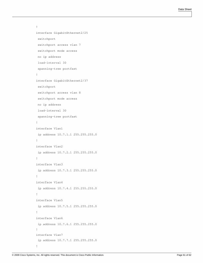
Data Sheet
© 2009 Cisco Systems, Inc. All rights reserved. This document is Cisco Public Information. Page 61 of 62
!
interface GigabitEthernet2/25
switchport
switchport access vlan 7
switchport mode access
no ip address
load-interval 30
spanning-tree portfast
!
interface GigabitEthernet2/37
switchport
switchport access vlan 8
switchport mode access
no ip address
load-interval 30
spanning-tree portfast
!
interface Vlan1
ip address 10.7.1.1 255.255.255.0
!
interface Vlan2
ip address 10.7.2.1 255.255.255.0
!
interface Vlan3
ip address 10.7.3.1 255.255.255.0
!
interface Vlan4
ip address 10.7.4.1 255.255.255.0
!
interface Vlan5
ip address 10.7.5.1 255.255.255.0
!
interface Vlan6
ip address 10.7.6.1 255.255.255.0
!
interface Vlan7
ip address 10.7.7.1 255.255.255.0
!
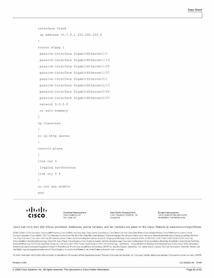
Data Sheet
© 2009 Cisco Systems, Inc. All rights reserved. This document is Cisco Public Information. Page 62 of 62
interface Vlan8
ip address 10.7.8.1 255.255.255.0
!
router eigrp 1
passive-interface GigabitEthernet1/1
passive-interface GigabitEthernet1/13
passive-interface GigabitEthernet1/25
passive-interface GigabitEthernet1/37
passive-interface GigabitEthernet2/1
passive-interface GigabitEthernet2/13
passive-interface GigabitEthernet2/25
passive-interface GigabitEthernet2/37
network 0.0.0.0
no auto-summary
!
ip classless
!
no ip http server
!
control-plane
!
line con 0
logging synchronous
line vty 0 4
!
no cns aaa enable
end
Printed in USA C11-553261-00 07/09


![Catalyst 6500 Release 12.2SX Software Configuration Guide - Virtual Switching Systems (VSS) [Cisco Catalyst 6500 Series Switches] - Cisco Systems](https://img.dokumen.tips/doc/110x75/55cf9e14550346d033b067ea/catalyst-6500-release-122sx-software-configuration-guide-virtual-switching.jpg)