Embed Size (px)
Citation preview
Senior MESA Day Prosthetic Arm Curriculum 1
These materials are for the internal use of MESA staff and teachers only
and should not be forwarded or used outside of MESA.
Biomedical Engineering – Prosthetic Arm I. Competition Overview
a. Review competition rules b. Discuss possible choices of materials for construction of model c. Emphasize prosthetic arm model specifications d. Emphasize display criteria, including synopsis, scaled plan rendering, and materials table
II. Overview of the Human Arm Anatomy .................................................................................3
a. Review Anatomical Terms of Location b. Review Bones of the Upper Extremity and Hand c. Review Joints d. Review Muscles of the Upper Arm, Forearm, and Hand e. Activity 1 – Bones and Joints of the Upper Extremity ....................................................16 f. Activity 2 – Muscles of the Upper Extremity ..................................................................18 g. Activity 3 – Fingers of the Hand......................................................................................20 h. Activity 4 – Internet Interactive Study Aids ....................................................................24
III. Overview of Biomedical Engineering ...................................................................................26
a. Review biomedical engineering b. Review key areas of biomedical engineering, including biotechnology, pharmaceuticals,
medical devices, and clinical engineering c. Activity 5: Designing a Career in Biomedical Engineering ............................................31 d. Activity 6: Biomedical Engineering Videos ....................................................................32
IV. Overview of Arm Motion ......................................................................................................33
a. Review kinematics, including types of motion, location of motion, direction of motion, magnitude of motion, and degrees of freedom
b. Activity 7: Degrees of Freedom .......................................................................................41 c. Activity 8: Build a Paper Robot Arm – Degrees of Freedom ..........................................42 d. Review kinetics, including extrinsic forces, intrinsic forces, force vectors, force of
gravity, reaction forces, additional linear forces, and classes of levers e. Activity 9: Physics Review ..............................................................................................56 f. Activity 10: Wooden Hydraulic Robot Arm ....................................................................57
Curr iculum

Senior MESA Day Prosthetic Arm Curriculum 2
These materials are for the internal use of MESA staff and teachers only
and should not be forwarded or used outside of MESA.
V. Overview of the Prosthetic Arm .............................................................................................60 a. Review artificial limbs, types, current technology, and immerging technology (including
robotic limbs) b. Activity 11: Build Your Own Robot Arm .......................................................................65
VI. Building the Model
a. Form 2-person student teams b. Review model specifications c. Encourage students to obtain materials found around the house or school – discourage
purchasing materials. Suggestions include foam board, dowels, card board, string, fishing wire, etc.
d. Remind students most points are awarded for cost and weight efficiency (the lowest cost to build and the lowest weight). Relate this to the real world – low cost to develop and low weight.
VIII. Building the Display
a. Review dimensions of the display b. Remind students of the scaled plan renderings c. Remind students to attach materials list

Senior MESA Day Prosthetic Arm Curriculum 3
These materials are for the internal use of MESA staff and teachers only
and should not be forwarded or used outside of MESA.
Section II: Review Anatomy of the Human Arm
Anatomical Terms of Location Three basic reference planes are used in human anatomy:
• Sagittal Plane – being a plane parallel to the sagittal suture (a dense, fibrous connective tissue joint between the two parietal bones of the skull), divides the body into sinister and dexter (left and right) portions.
o The midsagittal or median plane is the midline; i.e. it would pass through the mid line structures such as the navel or spine
• Coronal or Frontal Plane – divides the body into dorsal and ventral (back and front, or posterior and anterior) portions.
• Transverse Plane – divides the body into the cranial and caudal (head and tail) portions. The following is a list of more commonly used terms which describe the position of anatomical structures:
• Anterior: to the front or in front; also called ventral
• Posterior: to the rear or behind
• Superior: above
• Inferior: below
• Lateral: away from the median plane or midline
• Medial: towards the median plane or midline
• Distal: away from the trunk or root of the limb
• Proximal: close to the trunk or root of a limb
• Superficial: close to the surface of the body or skin
• Deep: away from the body surface or skin

Senior MESA Day Prosthetic Arm Curriculum 4
These materials are for the internal use of MESA staff and teachers only
and should not be forwarded or used outside of MESA.
Overview of the Anatomy of Human Arm
The human arm contains bones, joints, muscles, nerves and blood vessels. The skeletal anatomy of the arm consists of bones of the upper extremity and the bones of the hand.
Bones of the Upper Extremity
• The Humerus – the humerus is the longest and largest bone of the upper extremity. The smooth, dome-shaped head of the bone lies at an angle to the shaft and fits into a shallow socket of scapula (shoulder blade) to form the shoulder joint. Below the head, the bone narrows to form a cylindrical shaft. It flattens and widens at the lower end and, distally, it joins with the bones of the forearm (the ulna and radius) to make up the elbow joint.
• The Ulna – the ulna is a long bone in the forearm parallel with the radius, at the proximal is the elbow and at the distal end is the wrist. When the palm faces forward, the ulna is the inner bone (the one nearest to the body). The ulna is the forearm bone of the elbow, which flexes and extends at the elbow.

Senior MESA Day Prosthetic Arm Curriculum 5
These materials are for the internal use of MESA staff and teachers only
and should not be forwarded or used outside of MESA.
• The Radius – the radius is the other bone of the forearm, shorter than the ulna, and is situated lateral to the ulna. The disk-shaped head of the radius, which is smaller than the base, joins proximally at the humerus. The shaft has a broad base that joins distally with the ulna and the carpals to form the wrist joint. The radius is the forearm bone of the hand; the radius is the structure which, at the wrist, supports the hand.
Bones of the Hand
The human hand consists of 27 bones.
• The Carpus – the carpus, or wrist, is composed of 8 separate bones. The 8 carpals articulates on the proximal side with the radius and ulna of the forearm, and on the distal side with the metacarpus. The 8 carpals are arranged in two rows of four bones each. Those of the proximal row, from the radial to the ulnar side, are names the scaphoid, lunate, triquetrum, and pisiform; those of the distal row, in the same order, are names trapezium, trapezoid, capitate, and hamate.
• The Metacarpus – the metacarpus is the intermediate part of the hand skeleton that is located between the carpus which forms the connection to the forearm and the phalanges distally. The metacarpus consists of 5 metacarpal cylindrical bones that run from the base of the wrist, where they articulate with the carpals, to the base of each finger, where they articulate with the phalanges.
• The Phalanges of the Hand – the human hands contain 14
digital bones, also
called phalanges: 2 in the thumb (the thumb has no middle phalanx) and 3 in each of the four fingers. Each phalanx (finger) consists of a body: proximal phalanges, and two extremities, the intermediate phalanges and the distal phalanges which carry the fingernail (except the thumbs which have only distal phalanges and no intermediate phalanges).

Senior MESA Day Prosthetic Arm Curriculum 6
These materials are for the internal use of MESA staff and teachers only
and should not be forwarded or used outside of MESA.
Joints
A joint is the place where two bones meet. Because bones are hard, tough structures that resist movement individually, joints form new structures that can move. The elbow and wrist joints are characterized by a cavity that contains a fluid, called synovial fluid that provides lubrication. The ends of the adjacent bones have complementary shapes, which further reduces friction, and are covered with a layer of smooth, hard cartilage. These joints are completed enclosed by a baglike ligament that holds the joint together and prevents the synovial fluid from leaking out.
Elbow Joint/Complex
The elbow joint is the hinge joint between the distal end of the humerus and the proximal ends of the ulna and radius. Two main movements are possible at the elbow:
• The hinge-like bending and straightening of the elbow joint (flexion and extension) between the humerus and ulna; the joint acts like a door hinge and moves in only one plane.
• The complex action of turning the forearm over (pronation or supination) happens at the articulation between the radius and the ulna, the radio-ulnar joint, (this movement also occurs at the wrist joint).
Therefore, the elbow functions to move the arm like a hinge and in rotation allowing 2 degrees of freedom of
movement. In the anatomical position with the forearm supine (position of forearm when the palm faces anteriorly or faces up), the radius and ulna lie parallel to each other. During pronation (position of forearm when the palm faces posteriorly or faces down), the ulna remains fixed and the radius rolls around it at both the wrist and elbow joints. In the prone position, the radius and ulna appear crossed.
Most of the force through the elbow joint is transferred between the humerus and the ulna. Very little force is transmitted between the humerus and the radius. The elbow complex comprises three different portions:
• The humeroulnar joint lies between the ulna and humerus bones and is a simple hinge-joint.
• The humeroradial joint is the joint between the head of the radius and the capitulum of the humerus. This joint is an arthrodial joint, a plane joint allowing only gliding and sliding motions; this motion can be in any direction of a single plane.
• The proximal radioulnar joint is a trochoid or pivot joint that moves by rotating. This joint lies between the circumference of the head of the radius and the ring formed by the radial notch of the ulna and the annular ligament.
Senior MESA Day Prosthetic Arm Curriculum 7
These materials are for the internal use of MESA staff and teachers only
and should not be forwarded or used outside of MESA.
Wrist Joint
The wrist is the region between the forearm and the hand, known as the carpus. The wrist joint is a condyloid joint – one in which an ovoid head of one bone moves in an elliptical cavity of another. The wrist joint allows for 3 degrees of freedom of movement (flexion, extension, supination, pronation and circumduction). The wrist has three main joints:
• Radiocarpal Joint – the radiocarpal joint is formed by the radius, radioulnar disk, and 3 bones in the proximal carpal row: the scaphoid, lunate, and triquetrum. The proximal joint surface is a single biconcave curvature. It is long and shallow in the frontal plane (side to side) while being shorter and sharper in the frontal plane (anteroposterior). The curvature of the distal joint surface is sharper in both directions. The incongruency thus created in the joint allows for greater range of motion at this joint than if there were greater congruency. The distal radius is triangular in shape and flares distally. The distal lateral extension of the radius is the radial styloid. The distal articular surface of the radius is composed of two concave facets, one for articulation with the scaphoid and one for the lunate. The medial aspect of the distal radius (ulnar notch) is concave for its articulation with the ulna. A fibrocartilage disc is present at the distal end of the ulna and lies between the distal ulna and the triquetrum and lunate carpals. The disc is important for proper arthrokinematics of the distal radioulnar joint.
• Midcarpal Joint – the midcarpal joint is a functional rather than anatomical unit as it has no uninterrupted articular surface. However, the articular surface is generally concave-convex and has been considered a condyloid joint allowing 2 degrees of freedom of movement. It consists proximally of the scaphoid, lunate, and triquetrum articulating with the distal carpal row: the trapezium, trapezoid, capitate, and hamate.
• Carpometacarpal Joint – the carpometacarpal joints are the articulations between the distal row of carpals and the bases of the first through fifth metacarpals. The first carpometacarpal joint is the articulation between the first metacarpal and the trapezium. This articulation is a saddle joint, the first metacarpal is convex anterior/posterior and
Image from Hand Kinesiology, University of Kansas Medical Center (Lorie Richards and Janice Loudon)
intercarpal joints
carpometacarpal joint
midcarpal joint
radiocarpal joint

Senior MESA Day Prosthetic Arm Curriculum 8
These materials are for the internal use of MESA staff and teachers only
and should not be forwarded or used outside of MESA.
concave medial/lateral. The second metacarpal articualtes primarily with the trapezoid and secondarily with the trapezium and capitate. The third metacarpal articulates with the capitate. The fourth metacarpal articulates with the capitate and hamate and the fifth metacarpal articulates with the hamate.
• Intercarpal Joints – the intercarpal joints are the articulations between the individual carpal bones. They are plane synovial joints. The small amount of movement between the carpal bones at these joints contributes to total wrist mobility. The carpals together form an arch in the tranverse plane that is concave palmarly. This arch deepens with wrist flexion and flattens with wrist extension.
Metacarpophalangeal Joints
The metacarpophalangeal joints consist of the convex heads of the metacarpals articulating with the concave bases of the proximal phalanges. These are condyloid joints with 2 degrees of freedom of movement. These form the knuckles of the hand.
Interphalangeal Joints
The phalanges are the finger bones. The type of articulation between adjacent phalanges is a hinge joint. The articulation consists of the convex head of the proximal phalanx and the concave surface of the distal phalanx.
Muscles
Muscles are bands of fibrous tissue that have the ability to contract, producing movement in or maintaining the position of a part of the body. The muscles of the arm are skeletal muscle under the control of the somatic nervous system where contraction is stimulated by electrical impulses transmitted by the nerves and motor neurons. The skeletal muscle is linked to bones by bundles of collagen fibers known as tendons. Skeletal muscles are important in producing upper limb movement in flexion, extension, abduction, adduction, supination, pronation, and cirumduction.
• Flexion – a position that is made possible by the joint angle decreasing as in “bending” such as in bending the elbow
Image from Hand Kinesiology, University of Kansas Medical Center (Lorie Richards and Janice Loudon)
interphalangeal
joints

Senior MESA Day Prosthetic Arm Curriculum 9
These materials are for the internal use of MESA staff and teachers only
and should not be forwarded or used outside of MESA.
• Extension – a movement of a joint that results in increased angle between two bones as in “stretching” such as in straightening of the elbow
• Abduction – a movement which draws a limb away from the median (sagittal) plane of the body such as in moving the upper limb away from the side of the trunk
• Adduction – a movement which brings a limb closer to the sagittal plane of the body such as moving the upper limb back towards the side of the trunk
• Supination – a position of either the forearm or foot; in the forearm when the palm faces anteriorly, or faces up (when the arms are unbent and at the sides)
• Pronation – a position of the either the forearm or foot; in the forearm movement of the palm of the hand from an anterior-facing position to a posterior-facing position (faces down) without an associated movement at the shoulder. This corresponds to a counterclockwise twist for the right forearm and a closewise twist for the left.
• Circumduction – a movement in a circular manner. The movement pattern which is a combination of flexion, extension, adduction and abduction.
Upper Arm
The anterior compartment of the upper arm consists of the biceps brachii, brachialis, and coracobrachialis.
• In Latin, biceps
brachii means “two-headed [muscle] of the arm,” in reference to the fact that the muscle consists of two bundles of muscle, each with its own origin, sharing a common insertion point near the elbow joint. The biceps function most importantly to supinate the forearm and to flex the elbow. A sample activity is inserting a corkscrew and pulling out the cork.
Image courtesy of http://hippie.nu/~unicorn/tut/xhtml/
Senior MESA Day Prosthetic Arm Curriculum 10
These materials are for the internal use of MESA staff and teachers only
and should not be forwarded or used outside of MESA.
• The brachialis muscle lies just deep of the biceps brachii, and is a synergist that assists the biceps in flexing the elbow. It is the strongest flexor of the elbow.
• The coracobrachialis muscle attaches to the scapula and draws the humerus forward (shoulder flexion) and towards the torso (shoulder adduction).
The posterior compartment of the upper arm contains the triceps brachii, meaning “three-headed [muscle] of the arm.” The triceps brachii is a large muscle containing three heads (long, lateral, and medial). Some embryologists consider the anconeus the fourth head of the triceps, which is a small muscle that stabilizes the elbow joint during movement. The triceps is the main extensor of the forearm.
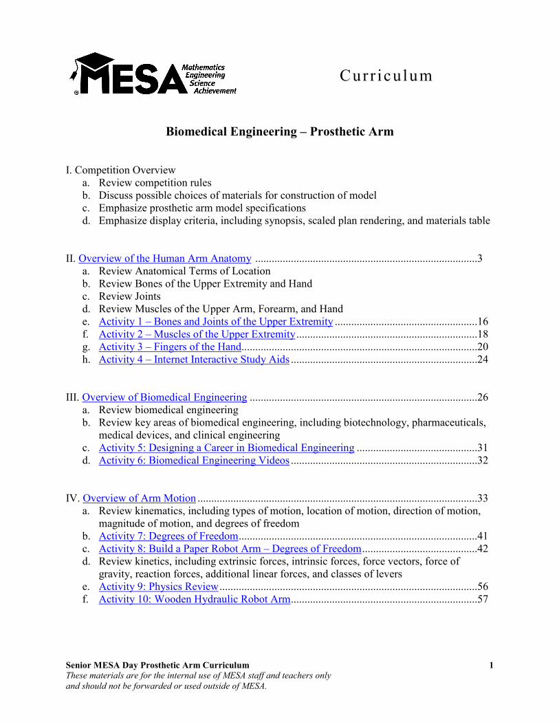
Forearm
The muscles of the forearm act on the elbow and wrist joints and on those of the phalanges. These muscles can be divided into flexor-pronator and extensor-supinator groups. The flexor-
pronator group arises by a common flexor tendon from the medial epicondyle of the humerus; this is referred to as the common flexor attachment or origin. The extensor supinator group arises by a common extensor tendon from the lateral epicondyle of the humerus; this is referred to as the common extensor attachment or origin. See table on next page for a listing of arm
muscles – flexor-pronator and extensor-supinator – and their functions.
Anterior of forearm Posterior of forearm

Senior MESA Day Prosthetic Arm Curriculum 11
These materials are for the internal use of MESA staff and teachers only
and should not be forwarded or used outside of MESA.
Arm Muscles and Their Functions
Muscle Location Function
Biceps brachii Anterior Arm (humerus) Flexion and supination of the elbow
Brachialis Anterior Arm (humerus) Flexion of elbow in all positions, but especially when the forearm is pronated
Triceps brachii Posterior Arm (humerus) Extension of the elbow
Brachioradialis Posterior/Anterior Forearm (superficial)
Flexion of elbow; also pronation and supination, depending on position of forearm
Pronator teres Anterior Forearm (superficial) Pronation of forearm; flexion of the elbow
Pronator quadratus Anterior Forearm (deep layer) Pronation of the forearm
Flexor carpi radialis Anterior Forearm (superficial) Flexion and abduction of the wrist
Palmaris longus Anterior Forearm (superficial) Flexion and abduction of the wrist
Flexor carpi ulnaris Anterior Forearm (superficial) Flexion and abduction of the wrist
Flexor digitorum superficialis Anterior Forearm (superficial) Flexion of the fingers
Flexor digitorum profundus Anterior Forearm (deep layer) Flexion of the fingers
Flexor pollicis longus Anterior Forearm (deep layer) Flexion of the thumb
Supinator Posterior Forearm (deep layer) Supination of forearm and wrist
Extensor carpi radialis longus Posterior Forearm (superficial) Extension and abduction of the wrist
Extensor carpi radialis brevis Posterior Forearm (superficial) Extension and abduction of the wrist
Extensor carpi ulnaris Posterior Forearm (superficial) Extension and adduction of the wrist
Extensor digitorum Posterior Forearm (superficial) Extension of the fingers
Extensor digiti minimi Posterior Forearm (superficial) Extension of the fingers
Extensor pollicis brevis Posterior Forearm (deep layer) Extension of the thumb
Extensor pollicis longus Posterior Forearm (deep layer) Extension of the thumb
Abductor pollicis longus Posterior Forearm (deep layer) Extension and abduction of the thumb
Senior MESA Day Prosthetic Arm Curriculum 12
These materials are for the internal use of MESA staff and teachers only
and should not be forwarded or used outside of MESA.
Hand
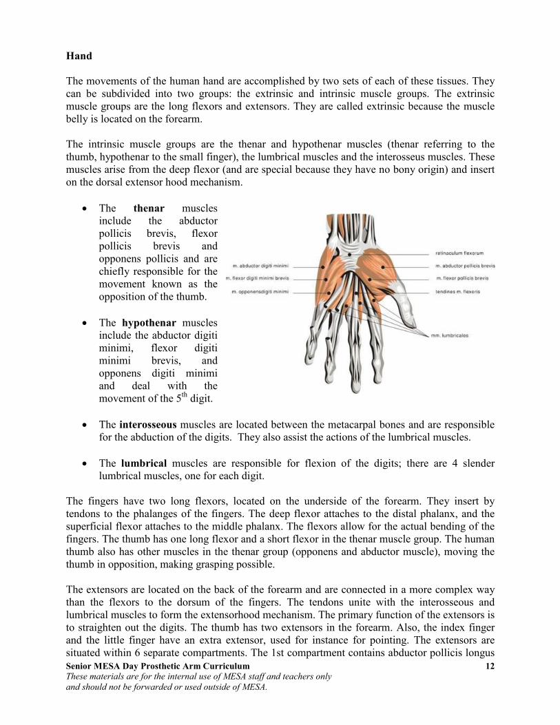
The movements of the human hand are accomplished by two sets of each of these tissues. They can be subdivided into two groups: the extrinsic and intrinsic muscle groups. The extrinsic muscle groups are the long flexors and extensors. They are called extrinsic because the muscle belly is located on the forearm. The intrinsic muscle groups are the thenar and hypothenar muscles (thenar referring to the thumb, hypothenar to the small finger), the lumbrical muscles and the interosseus muscles. These muscles arise from the deep flexor (and are special because they have no bony origin) and insert on the dorsal extensor hood mechanism.
• The thenar muscles include the abductor pollicis brevis, flexor pollicis brevis and opponens pollicis and are chiefly responsible for the movement known as the opposition of the thumb.
• The hypothenar muscles include the abductor digiti minimi, flexor digiti minimi brevis, and opponens digiti minimi and deal with the movement of the 5th digit.
• The interosseous muscles are located between the metacarpal bones and are responsible for the abduction of the digits. They also assist the actions of the lumbrical muscles.
• The lumbrical muscles are responsible for flexion of the digits; there are 4 slender lumbrical muscles, one for each digit.
The fingers have two long flexors, located on the underside of the forearm. They insert by tendons to the phalanges of the fingers. The deep flexor attaches to the distal phalanx, and the superficial flexor attaches to the middle phalanx. The flexors allow for the actual bending of the fingers. The thumb has one long flexor and a short flexor in the thenar muscle group. The human thumb also has other muscles in the thenar group (opponens and abductor muscle), moving the thumb in opposition, making grasping possible. The extensors are located on the back of the forearm and are connected in a more complex way than the flexors to the dorsum of the fingers. The tendons unite with the interosseous and lumbrical muscles to form the extensorhood mechanism. The primary function of the extensors is to straighten out the digits. The thumb has two extensors in the forearm. Also, the index finger and the little finger have an extra extensor, used for instance for pointing. The extensors are situated within 6 separate compartments. The 1st compartment contains abductor pollicis longus

Senior MESA Day Prosthetic Arm Curriculum 13
These materials are for the internal use of MESA staff and teachers only
and should not be forwarded or used outside of MESA.
and extensor pollicis brevis. The 2nd compartment contains extensors carpi radialis longus and brevis. The 3rd compartment contains extensor pollicis longus. The extensor digitorum indicis and extensor digititorum communis are within the 4th compartment. Extensor digiti minimi is in the fifth, and extensor carpi ulnaris is in the 6th.
Tendons
Tendons are tough bands of fibrous connective tissue that usually connects muscles to
bones and are capable of withstanding tension. Normal healthy tendons are mostly composed of parallel arrays of collagen fibers closed packed together. The dry mass of normal tendons, which makes up about 30% of the total mass in water, is comprised of about 86% collagen, 2% elastin, 1-5% proteoglycans, and 0.2% inorganic components such as copper, manganese, and calcium. Tendons have been traditionally considered to simply be a mechanism by which muscles connect to bone, functioning simply to transmit forces. However, over the past two decades, much research focused on the elastic properties of tendons and their ability to function as springs. This allows tendons to passively modulate forces during locomotion, providing additional stability with no active work. It also allows tendons to store and recover energy at high efficiency. For example, during a human stride, the Achilles tendon stretches as the ankle joint dorsiflexes. During the last portion of the stride, as the foot plantar-flexes (pointing the toes down), the stored elastic energy is released. Furthermore, because the tendon stretches, the muscle is able to function with less or even no change in length, allowing the muscle to generate greater force. The mechanical properties of the tendon are dependent on the collagen fiber diameter and orientation. The collagen fibrils are parallel to each other and closely packed, but show a wave-like appearance due to planar undulations, or crimps, on a scale of several micrometers. In tendons, the collagen I fibers have some flexibility due to the absence of hydroxyproline and proline residues at specific locations in the amino acid sequence, which allows the formation of other conformations such as bends or internal loops in the triple helix and results in the development of crimps. The crimps in the collagen fibrils allow the tendons to have some flexibility as well as a low compressive stiffness. In addition, because the tendon is a multi-stranded structure made up of many partially independent fibrils and fascicles, it does not behave as a single rod, and this property also contributes to its flexibility. The proteoglycan components of tendons also are important to the mechanical properties. While the collagen fibrils allow tendons to resist tensile stress, the proteoglycans allow them to resist compressive stress. The elongation and the strain of the collagen fibrils alone have been shown to be much lower than the total elongation and strain of the entire tendon under the same amount of stress, demonstrating that the proteoglycan-rich matrix must also undergo deformation, and stiffening of the matrix occurs at high strain rates. These molecules are very hydrophilic, meaning that they can absorb a large amount of water and therefore have a high swelling ratio. Since they are noncovalently bound to the fibrils, they may reversibly associate and disassociate
Senior MESA Day Prosthetic Arm Curriculum 14
These materials are for the internal use of MESA staff and teachers only
and should not be forwarded or used outside of MESA.
so that the bridges between fibrils can be broken and reformed. This process may be involved in allowing the fibril to elongate and decrease in diameter under tension.
Nerve Supply
The musculocutaneous nerve (from cervical spinal nerve 5, cervical spinal nerve 6 and cervical spinal nerve 7) is the main supplier of muscles of the anterior compartment. It originates from the lateral cord of the brachial plexus of nerves. It pierces the coracobrachialis muscle and gives off branches to the muscle, as well as to brachialis and biceps brachii. It terminates as the anterior cutaneous nerve of the forearm. The radial nerve, which is from the fifth cervical spinal nerve to the first thoracic spinal nerve, originates as the continuation of the posterior cord of the brachial plexus. This nerve enters the lower triangular space (an imaginary space bounded by, amongst others, the shaft of the humerus and the triceps brachii) of the arm and lies deep to the triceps brachii. Here it travels with a deep artery of the arm (the profunda brachii), which sits in the radial groove of the humerus. This fact is very important clinically as a fracture of the bone at the shaft of the bone here can cause lesions or even transections in the nerve. The median nerve, nerve origin C5-T1, which is a branch of the lateral and medial cords of the brachial plexus. This nerve continues in the arm, travelling in a plane between the biceps and triceps muscles. At the cubital fossa, this nerve is deep to the pronator tere muscle and is the most medial structure in the fossa. The nerve passes into the forearm. The ulnar nerve, origin C7-T1, is a continuation of the medial cord of the brachial plexus. This nerve passes in the same plane as the median nerve, between the biceps and triceps muscles. At the elbow, this nerve travels posterior to the medial epicondyle of the humerus. This means that condylar fractures can cause lesion to this nerve.
Blood Supply
The main artery in the arm is the brachial artery. This artery is a continuation of the axillary artery. The point at which the axillary becomes the brachial is distal to the lower border of teres major. The brachial artery gives off an important branch, the profunda brachii (deep artery of the arm). This branching occurs just below the lower border of teres major. The brachial artery continues to the cubital fossa, the triangular area on the anterior compartment of the elbow. It travels in a plane between the biceps and triceps muscles, the same as the median nerve and basilic vein. It is accompanied by venae comitantes (accompanying veins). It gives branches to the muscles of the anterior compartment. The artery is in between the median nerve and the tendon of the biceps muscle in the cubital fossa. It then continues into the forearm. The profunda brachii travels through the lower triangular space with the radial nerve. From here onwards it has an intimate relationship with the radial nerve. They are both found deep to the triceps muscle and are located on the spiral groove of the humerus. Therefore fracture of the bone may not only lead to lesion of the radial nerve, but also haematoma of the internal structures of the arm. The artery then continues on to anastamose with the recurrent radial branch of the brachial artery, providing a diffuse blood supply for the elbow joint.
Senior MESA Day Prosthetic Arm Curriculum 15
These materials are for the internal use of MESA staff and teachers only
and should not be forwarded or used outside of MESA.
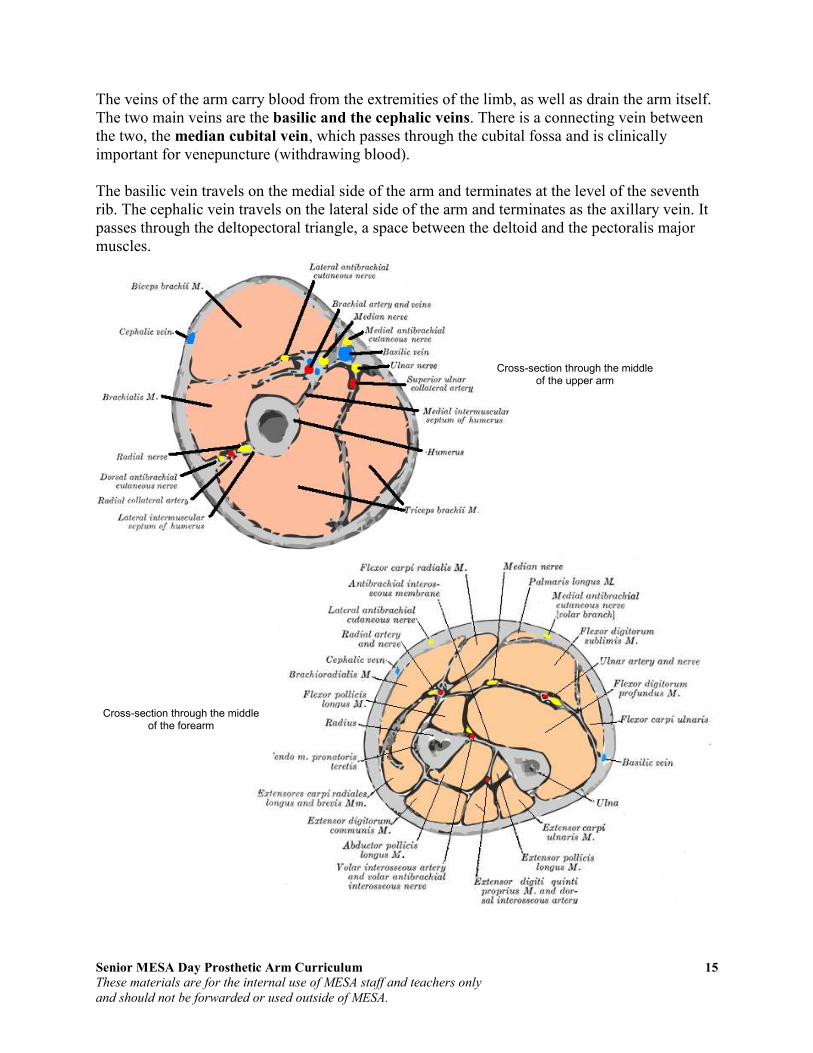
The veins of the arm carry blood from the extremities of the limb, as well as drain the arm itself. The two main veins are the basilic and the cephalic veins. There is a connecting vein between the two, the median cubital vein, which passes through the cubital fossa and is clinically important for venepuncture (withdrawing blood). The basilic vein travels on the medial side of the arm and terminates at the level of the seventh rib. The cephalic vein travels on the lateral side of the arm and terminates as the axillary vein. It passes through the deltopectoral triangle, a space between the deltoid and the pectoralis major muscles.
Cross-section through the middle of the forearm
Cross-section through the middle of the upper arm

Senior MESA Day Prosthetic Arm Curriculum 16
These materials are for the internal use of MESA staff and teachers only
and should not be forwarded or used outside of MESA.
Activity 1: Bones and Joints of the Upper Extremity
Directions: Correctly label the bones and joints below.

Senior MESA Day Prosthetic Arm Curriculum 17
These materials are for the internal use of MESA staff and teachers only
and should not be forwarded or used outside of MESA.
Activity 1: Bones and Joints of the Upper Extremity Solution
Solution:
Senior MESA Day Prosthetic Arm Curriculum 18
These materials are for the internal use of MESA staff and teachers only
and should not be forwarded or used outside of MESA.
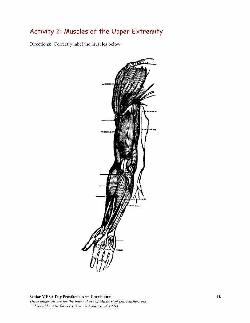
Activity 2: Muscles of the Upper Extremity
Directions: Correctly label the muscles below.

Senior MESA Day Prosthetic Arm Curriculum 19
These materials are for the internal use of MESA staff and teachers only
and should not be forwarded or used outside of MESA.
Activity 2: Muscles of the Upper Extremity Solution
Solution

Senior MESA Day Prosthetic Arm Curriculum 20
These materials are for the internal use of MESA staff and teachers only
and should not be forwarded or used outside of MESA.
Activity 3: Fingers of the Hand
Parts:
1 Model
10 Straws, fairly large diameter
String, small, like kite string
10 Beads
1 Paint paddle
10 Popsicle sticks
No tool box needed for this one but bring:
Glue gun
Saw or side cutters to cut paint paddle
Scissors
Tape, white or black
A few bamboo skewers to help push the strings through the straws.
These fingers really work. Make four with a thumb and you have a hand!
Concepts: 1. The Popsicle stick represents the bones in this project. They give the structure to the hand. 2. The strings represent the tendons in this project. They connect the bones to the muscles. 3. Your pull represents the muscles in this project. There are few muscles in the hand – the muscles in the
arm pull on the tendons that make the hand move.
Questions:
A. What are some differences between this hand and your hand? B. Our hands have two sets of tendons, one in front of the bones and one in back. What are the ones in
back for? C. What happens if your tendons break? D. Ligaments hook bones to other bones. What are the ligaments in this project?
Notes: Students may be frustrated at not being able to finish an entire hand; it takes a long time. To get around this, we present this project as fingers, and if students have the stamina, they can complete an entire hand. A single finger is still very nice.

Senior MESA Day Prosthetic Arm Curriculum 21
These materials are for the internal use of MESA staff and teachers only
and should not be forwarded or used outside of MESA.
How we build it:
One Finger Cut three pieces of Popsicle stick about 1/3 of the length of a full stick. Cut three pieces of straw slightly shorter than the sticks.
Glue the pieces of straw to the Popsicle pieces. Put the glue on the Popsicle piece not the straw or the straw may melt. Do this to all three pieces.
Glue all three stick segments onto a full straw. The sticks should be sandwiched between the straws now. Leave a small space in between each segment, so that bending is possible at each joint.
Cut the full straw’s excess but leave enough to glue it onto a full length Popsicle stick. Glue one more straw segment onto the top of the full length Popsicle stick in line with the other three segments.
Tie a bead onto the end of piece of string. Use the bamboo skewer to thread the other end of the string through all four short straw segments.

Senior MESA Day Prosthetic Arm Curriculum 22
These materials are for the internal use of MESA staff and teachers only
and should not be forwarded or used outside of MESA.
Tie a bead onto the other end of the string. This is one complete finger. Wrap each segment with tape to reinforce the glue. Masking tape works but black tape looks nice. Alternatively, you can just use tape and no glue to avoid burns, but it is harder to hold the small sections in the correct position as you tape them together. Pre-bend the finger at each joint.
You should be able to hold the long stick and pull the string to make the finger bend.
The whole hand Cut a paint paddle in half, then one half into two pieces, one about an inch shorter than the other. Glue the larger piece to the top of the full half of the paint paddle to form a T. Glue the smaller piece right underneath it.
Make three more fingers and a thumb. The thumb has one less segment than the other fingers. Glue the fingers to the paint paddle frame.
Glue on the thumb more towards the side of the hand. Each finger should move when pulling on its string.
A bit more info: In science, models help us understand the real thing. A model is similar to the real thing, but every model has its limitations. As work with a model, you must always think about what is similar and what is different from the real thing.

Senior MESA Day Prosthetic Arm Curriculum 23
These materials are for the internal use of MESA staff and teachers only
and should not be forwarded or used outside of MESA.
We move our bodies by muscles pulling on bones. Bones attach to bones with ligaments. Bones attach to muscles with tendons. Most of the muscles that pull on each segment of each of our fingers are actually in our forearm. If you put your hand palm-up on the table and move one finger at a time, you can see narrow lengths of muscles move in the forearm. Each of these muscles is connected to one bone in the hand through long tendons. The tendons move from the arm to the hand through the carpel tunnel. There are several major differences between this model and a real hand. In your hands there are actually three muscles going one each to the three bones of a finger. We usually use them all together, so many people are not able to move a single bone, say in the tip of a finger. Also, when we stop pulling a finger tight, it doesn’t snap back like the model finger does. We have another set of muscles and tendons going down the back of each finger that re-extends them on demand. If a tendon breaks, sometimes you can repair it. Ligaments are much more difficult to heal. The ligaments in this model are the long straws connecting the bones in the back of the finger. Muscles, bones, tendons and ligaments always work together, and if there is too much force put on the system, any of them may break.
Lesson Plan is courtesy of:
Curt Gabrielson Watsonville Community Science Workshop
For more information, please contact Curt Gabrielson at
Senior MESA Day Prosthetic Arm Curriculum 24
These materials are for the internal use of MESA staff and teachers only
and should not be forwarded or used outside of MESA.
Activity 4: Internet Interactive Study Aids
Go to the following website, WebAnatomy – University of Minnesota:
http://www.msjensen.gen.umn.edu/webanatomy/
1. Select “Bones” from the left column.
a. Take the “Upper Limb 1” interactive self-test.
Number correct out of 7
b. Take the “Humerus 1” interactive self-test.
Number correct out of 10
c. Take the “Hand (Manus)” interactive self-test.
Number correct out of 5
2. Return to home page and select “Muscles” from the left column.
a. Take the “Arm 1” interactive self-test (under “Arms, Legs, Etc.”)
Number correct out of 10
3. Return to the home page at http://www.msjensen.gen.umn.edu/webanatomy/ and select “Race Against the Clock – Timed Tests.”
a. Take the “Upper Limb” under “More Skeletal System” timed-test.
Note: There are six timed-tests; click on the small images at the top to load.
Number correct out of 6 Number correct out of 9 Number correct out of 9 Number correct out of 9 Number correct out of 8 Number correct out of 10

Senior MESA Day Prosthetic Arm Curriculum 25
These materials are for the internal use of MESA staff and teachers only
and should not be forwarded or used outside of MESA.
4. Return to the home page at http://www.msjensen.gen.umn.edu/webanatomy/ and select “Race Against the Clock – Timed Tests.”
a. Take the “Upper Limb Muscles” under “Muscular System” timed-test.
Note: There are four timed-tests; click on the small images at the top to load.
Number correct out of 9 Number correct out of 9 Number correct out of 11 Number correct out of 8

Senior MESA Day Prosthetic Arm Curriculum 26
These materials are for the internal use of MESA staff and teachers only
and should not be forwarded or used outside of MESA.
Section III: Review of Biomedical Engineering
Overview of Biomedical Engineering Biomedical engineering is the application of engineering technology to the fields of medicine and biology. It combines the design and problem solving skills of engineering with medical and biological sciences to improve the quality of life by developing and advancing medical care and technology. Biomedical engineering has only recently emerged as its own discipline, compared to many other engineering fields; such an evolution is common as a new field transitions from being an interdisciplinary specialization among already-established fields, to being considered a field in itself. Much of the work in biomedical engineering consists of research and development, spanning a broad array of subfields. Prominent biomedical engineering applications include the development of biocompatible prostheses, various diagnostic and therapeutic medical devices ranging from clinical equipment to micro-implants, common imaging equipment such as MRIs and EEGs, biotechnologies such as regenerative tissue growth, and pharmaceutical drugs & biopharmaceuticals. Biomedical engineering is a highly interdisciplinary field, influenced by (and overlapping with) various other engineering and medical fields. This often happens with newer disciplines, as they gradually emerge in their own right after evolving from special applications of extant disciplines. Due to this diversity, it is typical for a biomedical engineer to focus on a particular subfield or group of related subfields. There are many different taxonomic breakdowns within BME, as well as varying views about how best to organize them and manage any internal overlap; the main U.S. organization devoted to BME, BMES (the Biomedical Engineering Society), divides the major specialty areas as follows:
- Bioinstrumentation - Biomaterials - Biomechanics - Cellular, Tissue, and Genetic Engineering - Clinical Engineering - Medical Imaging - Orthopaedic Bioengineering - Rehabilitation Engineering - Systems Physiology
Sometimes, disciplines within BME are classified by their association(s) with other, more established engineering fields, which can include:
- Chemical engineering - often associated with biochemical, cellular, molecular and tissue engineering, biomaterials, and biotransport.

Senior MESA Day Prosthetic Arm Curriculum 27
These materials are for the internal use of MESA staff and teachers only
and should not be forwarded or used outside of MESA.
- Electrical engineering - often associated with bioelectrical and neural engineering, bioinstrumentation, biomedical imaging, and medical devices. This also tends to encompass Optics and Optical engineering - biomedical optics, imaging and related medical devices.
- Mechanical engineering - often associated with biomechanics, biotransport, medical devices, and modeling of biological systems.
Biotechnology and Pharmaceuticals
Biotechnology can be a somewhat ambiguous term -- in its broadest form occasionally encompassing all of BME; however, it more typically denotes specific products which use "biological systems, living organisms, or derivatives thereof." Even some complex "medical devices" (see below) can reasonably be deemed "biotechnology" depending on the degree to which such elements are central to their principal of operation. Biologics/Biopharmaceuticals (e.g., vaccines, stored blood product), genetic engineering, and various agricultural applications are some major classes of biotechnology. Pharmaceuticals are related to biotechnology in two indirect ways: 1) certain major types (e.g. biologics) fall under both categories, and 2) together they essentially comprise the "non-medical-device" set of BME applications. (The "Device - Bio/Chemical" spectrum is an imperfect dichotomy, but one regulators often use, at least as a starting point.)
Tissue engineering Tissue Engineering is a major segment of Biotechnology which has developed the ability to take cells out of person and keep them alive in culture for an extended period of time. This has enabled researchers to study how cells work. One of the goals of tissue engineering is to create artificial organs (via biological material) for patients that need organ transplants. Biomedical engineers are currently researching methods of creating such organs. In one case bladders have been grown in the laboratory and transplanted successfully into patients. In another case, skin cells have been replicated outside of the body and encouraged to form new tissue. This tissue-engineered skin has been used to treat patients with severe burns. Bioartificial organs, which use both synthetic and biological components, are also a focus area in research, such as with hepatic assist devices that use liver cells within an artificial bioreactor construct. Genetic engineering Genetic engineering, recombinant DNA technology, genetic modification/ manipulation (GM) and gene splicing are terms that apply to the direct manipulation of an organism's genes. Genetic engineering is different from traditional breeding, where the organism's genes are manipulated indirectly. Genetic engineering uses the techniques of
Micromass cultures of C3H-10T1/2 cells at varied oxygen tensions stained with Alcian blue.

Senior MESA Day Prosthetic Arm Curriculum 28
These materials are for the internal use of MESA staff and teachers only
and should not be forwarded or used outside of MESA.
molecular cloning and transformation to alter the structure and characteristics of genes directly. Genetic engineering techniques have found success in numerous applications. Some examples are in improving crop technology, the manufacture of synthetic human insulin through the use of modified bacteria, the manufacture of erythropoietin in hamster ovary cells, and the production of new types of experimental mice such as the oncomouse (cancer mouse) for research. Pharmaceutical engineering Pharmaceutical Engineering is sometimes regarded as a branch of biomedical engineering, and sometimes a branch of chemical engineering; in practice, it is very much a hybrid sub-discipline (as many BME fields are). Aside from those pharmaceutical products directly incorporating biological agents or materials, even developing chemical drugs is considered to require substantial BME knowledge due to the physiological interactions inherent to such products' usage.
Medical devices
This is an extremely broad category -- essentially covering all healthcare products that do not achieve their intended results through predominantly chemical (e.g., pharmaceuticals) or biological (e.g., vaccines) means, and do not involve metabolism. A medical device is intended for use in:
• the diagnosis of disease or other conditions, or
• in the cure, mitigation, treatment, or prevention of disease,
Some examples include pacemakers, infusion pumps, the heart-lung machine, dialysis machines, artificial organs,
implants, artificial limbs, corrective lenses, cochlear implants, ocular prosthetics, facial prosthetics, somato prosthetics, and dental implants. Specifically, artificial organs and devices have replaced the function and natural organ in the body such as an artificial heart made of synthetic materials to replace an actual heart of the body and an artificial hip made of metal to replace the hip due to severe joint damage. Stereolithography is a practical example of medical modeling being used to create physical objects. Beyond modeling organs and the human body, emerging engineering techniques are also currently used in the research and development of new devices for innovative therapies, treatments, patient monitoring, and early diagnosis of complex diseases.
A pump for continuous subcutaneous insulin infusion, an example of a biomedical engineering application of electrical engineering to medical equipment
Biomedical instrumentation amplifier schematic used in monitoring low voltage biological signals, an example of a biomedical engineering application of electronic engineering to electrophysiology

Senior MESA Day Prosthetic Arm Curriculum 29
These materials are for the internal use of MESA staff and teachers only
and should not be forwarded or used outside of MESA.
Medical devices are regulated and classified (in the US) as follows:
• Class I devices present minimal potential for harm to the user and are often simpler in design than Class II or Class III devices. Devices in this category include tongue depressors, bedpans, elastic bandages, examination gloves, and hand-held surgical instruments and other similar types of common equipment.
• Class II devices are subject to special controls in addition to the general controls of Class I devices. Special controls may include special labeling requirements, mandatory performance standards, and postmarket surveillance. Devices in this class are typically non-invasive and include x-ray machines, PACS, powered wheelchairs, infusion pumps, and surgical drapes.
• Class III devices generally require premarket approval, a scientific review to ensure the device's safety and effectiveness, in addition to the general controls of Class I. Examples include replacement heart valves, silicone gel-filled breast implants, implanted cerebellar stimulators, implantable pacemaker pulse generators and endosseous (intra-bone) implants.
Medical imaging Medical/Biomedical Imaging is a major segment of Medical Devices. This area deals with enabling clinicians to directly or indirectly "view" things not visible in plain sight (such as due to their size, and/or location). This can involve utilizing ultrasound, magnetism, UV, other radiology, and other means. Medical/biomedical imaging takes physical principles of how ultrasound, magnetism and x-rays interact with the tissues of the body and takes that physical principle to develop pictures of what is inside the body. Imaging technologies are often essential to medical diagnosis, and are typically the most complex equipment found in a hospital including:
- Fluoroscopy - Magnetic resonance imaging (MRI) - Nuclear Medicine - Positron Emission Tomography (PET) scans - Projection Radiography such as X-rays and CT scans - Tomography - Ultrasound - Electron Microscopy
An MRI scan of a human head, an example of a biomedical engineering application of electrical engineering to diagnostic imaging.
Senior MESA Day Prosthetic Arm Curriculum 30
These materials are for the internal use of MESA staff and teachers only
and should not be forwarded or used outside of MESA.
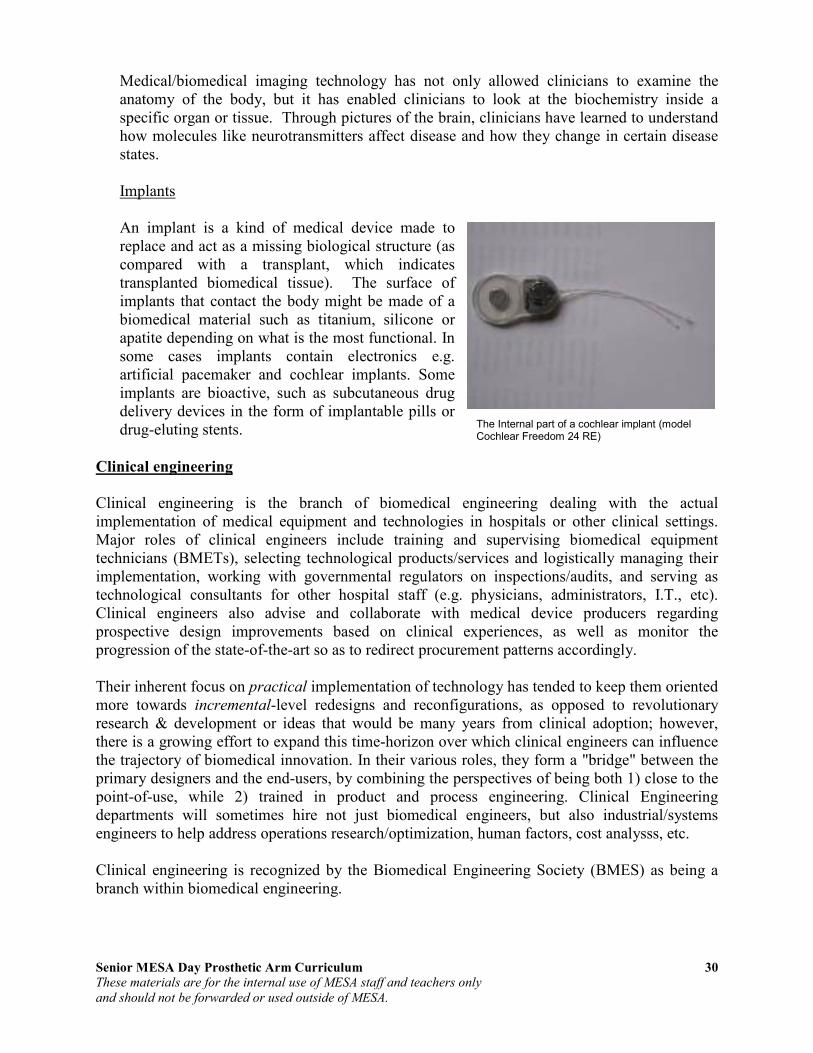
Medical/biomedical imaging technology has not only allowed clinicians to examine the anatomy of the body, but it has enabled clinicians to look at the biochemistry inside a specific organ or tissue. Through pictures of the brain, clinicians have learned to understand how molecules like neurotransmitters affect disease and how they change in certain disease states. Implants An implant is a kind of medical device made to replace and act as a missing biological structure (as compared with a transplant, which indicates transplanted biomedical tissue). The surface of implants that contact the body might be made of a biomedical material such as titanium, silicone or apatite depending on what is the most functional. In some cases implants contain electronics e.g. artificial pacemaker and cochlear implants. Some implants are bioactive, such as subcutaneous drug delivery devices in the form of implantable pills or drug-eluting stents.
Clinical engineering
Clinical engineering is the branch of biomedical engineering dealing with the actual implementation of medical equipment and technologies in hospitals or other clinical settings. Major roles of clinical engineers include training and supervising biomedical equipment technicians (BMETs), selecting technological products/services and logistically managing their implementation, working with governmental regulators on inspections/audits, and serving as technological consultants for other hospital staff (e.g. physicians, administrators, I.T., etc). Clinical engineers also advise and collaborate with medical device producers regarding prospective design improvements based on clinical experiences, as well as monitor the progression of the state-of-the-art so as to redirect procurement patterns accordingly. Their inherent focus on practical implementation of technology has tended to keep them oriented more towards incremental-level redesigns and reconfigurations, as opposed to revolutionary research & development or ideas that would be many years from clinical adoption; however, there is a growing effort to expand this time-horizon over which clinical engineers can influence the trajectory of biomedical innovation. In their various roles, they form a "bridge" between the primary designers and the end-users, by combining the perspectives of being both 1) close to the point-of-use, while 2) trained in product and process engineering. Clinical Engineering departments will sometimes hire not just biomedical engineers, but also industrial/systems engineers to help address operations research/optimization, human factors, cost analysss, etc. Clinical engineering is recognized by the Biomedical Engineering Society (BMES) as being a branch within biomedical engineering.
The Internal part of a cochlear implant (model Cochlear Freedom 24 RE)

Senior MESA Day Prosthetic Arm Curriculum 31
These materials are for the internal use of MESA staff and teachers only
and should not be forwarded or used outside of MESA.
Activity 5: Designing a Career in Biomedical Engineering
Review publication “Designing a Career in Biomedical Engineering". This publication, produced by the Engineering in Medicine and Biology Society of IEEE, can be downloaded from the MESA Day Curriculum website or at www.embs.org/docs/careerguide.pdf.
Notes for Students: What do biomedical engineers do? How do biomedical engineers differ from other engineers? How much education does a biomedical engineer require? How can a high school education prepare me for studies in biomedical engineering? What types of university courses will prepare me to become a biomedical engineer? What kind of practical experience can I expect to gain while training to be a biomedical engineer? What are some of the key areas of biomedical engineering?
Senior MESA Day Prosthetic Arm Curriculum 32
These materials are for the internal use of MESA staff and teachers only
and should not be forwarded or used outside of MESA.
Activity 6: Biomedical Engineering Videos
1. Introduction to Biomedical Engineering Video
Biomedical Engineering – All Things Science (1 min 21 sec) Go to the following website to view the video:
http://www.allthingsscience.com/video/54/Biomedical-Engineering
2. Engineering Profile Videos at Engineering Your Future
Go to the following website to view the videos: http://www.futuresinengineering.org
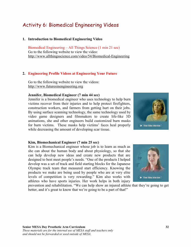
Jennifer, Biomedical Engineer (7 min 44 sec)
Jennifer is a biomedical engineer who uses technology to help burn victims recover from their injuries and to help protect firefighters, construction workers, and farmers from getting hurt on their jobs. By using surface scanning technology, the same technology used by video game designers and filmmakers to create life-like 3D animations, she and other engineers build customized burn masks for burn victims. These masks help victims’ faces heal properly while decreasing the amount of developing scar tissue.
Kim, Biomechanical Engineer (7 min 25 sec)
Kim is a Biomechanical engineer whose job is to learn as much as she can about the human body and about physiology, so that she can help develop new ideas and create new products that are designed to best meet people’s needs. “One of the products I helped develop was a set of track and field starting blocks for the Japanese Olympic track team that measured start efficiency. Knowing the products we make are being used by people who are at very elite levels of competition is very rewarding.” Kim also works with athletes who have sports injuries. Her work helps in both injury prevention and rehabilitation. “We can help show an injured athlete that they’re going to get better, and it’s great to know that we’re going to be a part of that!”

Senior MESA Day Prosthetic Arm Curriculum 33
These materials are for the internal use of MESA staff and teachers only
and should not be forwarded or used outside of MESA.
Section IV: Review of Arm Motion
Biomechanics Understanding joint motion requires knowledge of the physical principles that govern the body and of the forces that affect the body. The study of mechanics allows for an understanding of the structure and function of the arm and its motion, the act or process of changing position or place. In the human body, the study of mechanics is called biomechanics and consists of kinematics and kinetics. Kinematics is the branch of classical mechanics that describes motion without consideration of the causes leading to the motion. Kinetics, on the other hand, is concerned with the relationship between the motion and its causes.
Kinematics
Types of Motion
• Translatory motion is the movement of an object in which all parts of the moving body move toward the same direction. With translation, all points of the body move along parallel paths and have the same velocity and acceleration at any given instant.
o Linear or rectilinear motion is the movement of an object in which all parts of a moving body move in the same direction follows a straight line.
o Curvilinear motion is motion in which the net motion of a moving body moves toward the same direction although the path follows a curved line.
• Rotatory, or angular motion is the movement of an object around a fixed axis, called the axis of rotation. During rotatory motion, all parts of the body travel in the same direction through the same angle of rotation. With rotation, all parts of the body, except those that lie on the axis of rotation, move in parallel planes along concentric circles centered on the same fixed axis. The angel of rotation is measured on a plane perpendicular to the axis.
• General motion is a combination of translation and rotation. At any given instant, the general motion is equal to the sum of the translation along and the rotation about an instantaneous axis.
Location of Motion
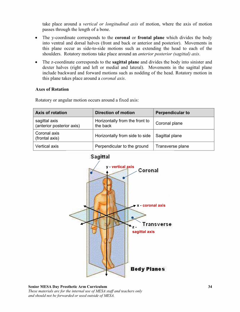
Three cardinal planes which are orthogonal, meaning the three axes are at right angles to each other, are used to describe the location of motion. Using the Cartesian coordinate system, motion at a joint is described as occurring in the transverse, coronal or sagittal planes. Motion occurs in any one of these planes in which a body segment is being rotated about its axis in such a way that is parallel to one of these planes.
• The x-coordinate corresponds to the transverse or horizontal plane which divides the body into cranial and caudal portions (upper and lower or superior and inferior halves). Movements in this plane occur parallel to the ground. In particularly, rotatory motions
Senior MESA Day Prosthetic Arm Curriculum 34
These materials are for the internal use of MESA staff and teachers only
and should not be forwarded or used outside of MESA.
take place around a vertical or longitudinal axis of motion, where the axis of motion passes through the length of a bone.
• The y-coordinate corresponds to the coronal or frontal plane which divides the body into ventral and dorsal halves (front and back or anterior and posterior). Movements in this plane occur as side-to-side motions such as extending the head to each of the shoulders. Rotatory motions take place around an anterior posterior (sagittal) axis.
• The z-coordinate corresponds to the sagittal plane and divides the body into sinister and dexter halves (right and left or medial and lateral). Movements in the sagittal plane include backward and forward motions such as nodding of the head. Rotatory motion in this plane takes place around a coronal axis.
Axes of Rotation
Rotatory or angular motion occurs around a fixed axis:
Axis of rotation Direction of motion Perpendicular to
sagittal axis (anterior posterior axis)
Horizontally from the front to the back
Coronal plane
Coronal axis (frontal axis)
Horizontally from side to side Sagittal plane
Vertical axis Perpendicular to the ground Transverse plane
y - vertical axis
z -
sagittal axis
x - coronal axis

Senior MESA Day Prosthetic Arm Curriculum 35
These materials are for the internal use of MESA staff and teachers only
and should not be forwarded or used outside of MESA.
C 3.6 m 3 m 2 m B A
Direction of Motion
• Movements of the upper extremity in the transverse plane about a vertical axis
o Lateral or external rotation: the anterior surface of the distal segment moves outwards
o Medial or internal rotation: the anterior surface of the distal segment moves inwards
o Supination / pronation: used for forearm movements o Horizontal abduction / horizontal adduction: used for shoulder movements
• Movements of the upper extremity in the coronal plane about a sagittal axis
o Abduction: the distal segment moves away from the midsagittal (midline) of the body
o Adduction: the distal segment moves towards the midsagittal (midline) of the body
o Exception: finger movements o Radial deviation / ulnar deviation: used for wrist or thumb movements
• Movements of the upper extremity in the sagittal plane about a coronal axis
o Flexion: the angle of a joint becomes smaller o Extension: the angle of a joint becomes larger
• Other kinds of movements of the upper extremity
o Movements in a combination of planes � Circumduction: the distal segment follows the surface of a cone and the tip
of the segment trace a circular path � Finger opposition
o Thumb movements � Flexion / extension � Abduction / adduction in a plane perpendicular to the palm
Magnitude of Motion
Translatory motions are quantified by linear distance through which the object or segment has moved.
• Displacement is the change of position that an object moves from the reference point.
o has direction o the magnitude of change (amplitude) ≠
distance o example: a person walks west for 2 m and
then north for 3 m. The distance traveled equals to 2 m + 3 m = 5 m. But the
amplitude of displacement equals to √(22 +
32) = 3.6 m.

Senior MESA Day Prosthetic Arm Curriculum 36
These materials are for the internal use of MESA staff and teachers only
and should not be forwarded or used outside of MESA.
• Velocity is the rate of change in displacement. o v = dx / dt
o the magnitude of change (amplitude) ≠ speed o has direction
o The instant velocity vector v of an object that has positions x(t) at time t and x(t
+ ∆t) at time t + ∆t, can be computed as the derivative of position:
• Acceleration is the rate of change in velocity over time.
o a = dv / dt o amplitude o direction
• The relationship between displacement, velocity and acceleration, can be expressed as: o x = v0t + (1/2)at2 o v = v0 + at o average velocity = (v0 + v) / 2
The magnitude of rotatory or angular motion (range of motion) can be expressed as:
• Angular displacement measures the rotation of an object about an axis in radians. o A radian is the ratio of an arc to the radius of its circle
� 1 radian = 57.3°
� 1° = 0.01745 radians
o ∆θ = ∆θ2 − ∆θ1
� whereas s is the length of arc and r is the radius
• Angular velocity is the time rate at which an object rotates, or revolves, about an axis, or at which the angular displacement between two bodies changes. Angular velocity,
represented by the symbol ω, is expressed in radians per second.
o
o
• Angular acceleration is the change of angular velocity over time.
o

Senior MESA Day Prosthetic Arm Curriculum 37
These materials are for the internal use of MESA staff and teachers only
and should not be forwarded or used outside of MESA.
Degrees of Freedom of a Rigid Body (Mechanics)
The degrees of freedom (DOF) of a rigid body is defined as the number of independent movements it has. Figure 4-1 shows a rigid body in a plane. To determine the DOF of this body we must consider how many distinct ways the bar can be moved. In a
two dimensional plane such as this computer screen or sheet of paper, there are 3 DOF. The bar can be translated along the x axis, translated along the y axis, and rotated about its centroid. An unrestrained rigid body in space has six degrees of freedom: three translating motions along the x, y and z axes and three rotary motions around the x, y and z axes respectively. Figure 4-2 shows a rigid body in a space.
A joint which moves substantially in one plane (like an elbow) is uniaxial. One which moves in two planes is biaxial, and one which moves in three planes is triaxial. A ball and socket such as the shoulder joint is multiaxial, but is equivalent to a triaxial as it has three degrees of freedom i.e. all movements can be reduced to XYZ axes. In a three-dimensional space, the six degrees of freedom of a rigid body are:
1. Moving up and down
2. Moving left and right
3. Moving forward and backward
4. Tilting forward and backward (pitch)
5. Turning left and right (yaw)
6. Tilting side to side (roll)
A human arm has 7 mechanical degrees of freedom (3 in the shoulder, 1 in the elbow, and 3 in the wrist): Shoulder has three degrees of freedom: pitch, yaw and roll.
• 240° pitch
• 180° yaw
• 90° roll Elbow has one degree of freedom: pitch.
• 150° pitch
Figure 4-1: Degrees of freedom of a rigid body in a plane
Figure 4-2: Degrees of freedom of a rigid body in a space
Senior MESA Day Prosthetic Arm Curriculum 38
These materials are for the internal use of MESA staff and teachers only
and should not be forwarded or used outside of MESA.
Wrist has three degrees of freedom: bend up and down (pitch), move side to side (yaw), and it can also twist a little (roll).
• 170° pitch
• 70° yaw
• 90° roll
Degrees of freedom (Df) within movement
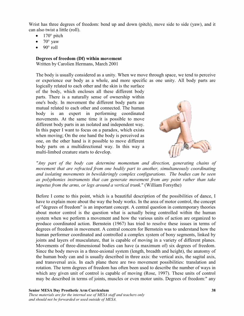
Written by Carolien Hermans, March 2001 The body is usually considered as a unity. When we move through space, we tend to perceive or experience our body as a whole, and more specific as one unity. All body parts are logically related to each other and the skin is the surface of the body, which encloses all these different body parts. There is a naturally sense of ownership within one's body. In movement the different body parts are mutual related to each other and connected. The human body is an expert in performing coordinated movements. At the same time it is possible to move different body parts in an isolated and independent way. In this paper I want to focus on a paradox, which exists when moving; On the one hand the body is perceived as one, on the other hand is it possible to move different body parts on a multidirectional way. In this way a multi-limbed creature starts to develop. "Any part of the body can determine momentum and direction, generating chains of
movement that are refracted from one bodily part to another, simultaneously coordinating
and isolating movements in bewilderingly complex configurations. The bodies can be seen
as polyphonies instruments that can generate movement from any point rather than take
impetus from the arms, or legs around a vertical trunk." (William Forsythe) Before I come to this point, which is a beautiful description of the possibilities of dance, I have to explain more about the way the body works. In the area of motor control, the concept of "degrees of freedom" is an important concept. A central question in contemporary theories about motor control is the question what is actually being controlled within the human system when we perform a movement and how the various units of action are organized to produce coordinated action. Bernstein (1967) has tried to resolve these issues in terms of degrees of freedom in movement. A central concern for Bernstein was to understand how the human performer coordinated and controlled a complex system of bony segments, linked by joints and layers of musculature, that is capable of moving in a variety of different planes. Movements of three-dimensional bodies can have (a maximum of) six degrees of freedom. Since the body moves in a three-axional system (length, breadth and height), the anatomy of the human body can and is usually described in three axis: the vertical axis, the sagital axis, and transversal axis. In each plane there are two movement possibilities: translation and rotation. The term degrees of freedom has often been used to describe the number of ways in which any given unit of control is capable of moving (Rose, 1997). These units of control may be described in terms of joints, muscles or even motor units. Degrees of freedom:" any
Senior MESA Day Prosthetic Arm Curriculum 39
These materials are for the internal use of MESA staff and teachers only
and should not be forwarded or used outside of MESA.
of a limited number of ways in which a body may move or in which a dynamic system may change".(Webster's dictionary, 1986) We can describe the human body on the level of joints, muscles or even motor units. If what we control during movement are the joints, Turvey and colleagues (1982; see Rose 1997) estimate that a total of seven degrees of freedom must be controlled just to move the arm (three degrees of freedom at the shoulder, one at both the elbow and the radio-ulnar joint and two at the wrist joint). If we go a step further and consider the muscle the unit that is controlled during the movement, the number of degrees of freedom rises dramatically. In order to move that same arm again, we must now regulate 26 degrees of freedom. As you might expect the estimated number rises exponentially when the motor unit is considered the unit of control. You can see the overwhelming problem of controlling the many hundreds and thousands of degrees of freedom available within the human motor system (Abernethy and Sparrow, 1992). This is an issue which hasn't be clarified until now. However there are some assumptions, which give an explanation of human control and learning. First it is assumed that the human body operates in "functional collectives" or "coordinative structures" within a finite and limited class of movements. A compelling argument is the next one: we could never handle the 6 df of the millions of cells in our body. It is simply too much. Second: If you were to control the individual cells directly, you could specify values for their trajectories, which you could never achieve because they violate the constraints on collectives of cells. In other words: controlling the body on a cell level could lead to movements, which are impossible to perform... (Fowler and Turvey, 1978). By controlling the few degrees of freedom of the collective, the actor thereby regulates the many degrees of freedom of the components. An actor controls groups of muscles rather than individual muscles. In short: It is impossible to consider every movement possibility of the millions of cells in your body. Instead I would like to speak of the movement possibilities of "coordinated structures" at the level of the joints. Every joint in the body, with its own number of degrees of freedom, can be a starting point for movement. The joint, which relates two body parts, can generate a finite number of movements. In the table below, you will find the movement possibilities of the joints.
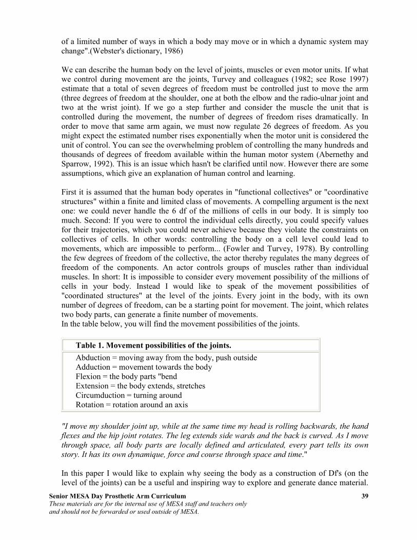
Table 1. Movement possibilities of the joints.
Abduction = moving away from the body, push outside Adduction = movement towards the body Flexion = the body parts "bend Extension = the body extends, stretches Circumduction = turning around Rotation = rotation around an axis
"I move my shoulder joint up, while at the same time my head is rolling backwards, the hand
flexes and the hip joint rotates. The leg extends side wards and the back is curved. As I move
through space, all body parts are locally defined and articulated, every part tells its own
story. It has its own dynamique, force and course through space and time." In this paper I would like to explain why seeing the body as a construction of Df's (on the level of the joints) can be a useful and inspiring way to explore and generate dance material.
Senior MESA Day Prosthetic Arm Curriculum 40
These materials are for the internal use of MESA staff and teachers only
and should not be forwarded or used outside of MESA.
The body can be seen as one unit, it can also be seen as a many units organism. From every joint in the body several movements in different planes can start to evolve. I would like to speak of a deconstruction of the body in smaller units, to the units of the joints. "The deconstruction of the moving body is a transformatios. This dismantle of the moving
body wants to explore the movements possibilities and come to an active transformation,
deformation or innovation of the dance material. She wants to pull the movements out of her
natural and logic environment and place them in another one. The deconstruction of the total
moving body into smaller or smallest segments of movements can result in a refraction of
movements. This is to destabilize or stabilize the chain of movements, to refract the whole
body, to balance between the moving segments, to confuse, to disarrange, to disturb and
interfere with the internal logic of the movement, to deform, to disorder and order again, to
disturb the system, to break open and to fragment every body part." The whole body can move as one unit, moving around its vertical axis with a central mass point. It is however also possible to deconstruct the body in smaller units. Joints can be seen as places where voluntary bodies move with respect to each other. Many bodies move within one body, in an isolated and highly structured and coordinated way. These local convulsions or outbursts of movement can be highly controlled.Every joint has its local axis and local mass point. From there the movement starts. It describes an individual pattern through space, well defined and articulated. Together with all the other local movements, the body becomes a complex of movement strings generated out of local focus points. Every joint has to deal with gravitational, frictional and contact forces. The joint has to place itself in a certain position, using muscular activity at a certain velocity with a certain force. This is a fragmentation of the body. Every joint has its own number of degrees of freedom (which more or less depends on the form of the joint), its own degree of flexibility and rigid ness. This also means that every joint has its own quality of movement: from flexion, tension, adduction, abduction to rotation and circumduction. In training your body, the number of controllable biokinematic degrees of freedom increases that is synonymous with becoming more expert. In becoming an expert, you can drive your body to complexity, moving every joint in an independent and coordinated way, break the internal movement logic and build up another one. It is highly controlled, even the local outbursts of movements, because the body needs a strong sense of coordinating movements. The chaos of a multi-limbed creature in which every body part generates its own movement with its own momentum, direction and course, is a controlled one. This coordination of movement is the process of mastering the degrees of freedom of every moving organ, in other words its conversion to a controllable system (Fowler and Turvey, 1987). In this paper I tried to explain the distinction between moving the total body from a central mass point and vertical axis and the local movements at the joints with their own mass point and axis. Of course it is impossible to make a sharp distinction: there is a whole continuum of movements, the joints are mutually related and highly dependent. In using the available Df's at every joint, it is possible to develop a refined and articulated moving body. It is a way of generating local movements in a highly coordinated system.

Senior MESA Day Prosthetic Arm Curriculum 41
These materials are for the internal use of MESA staff and teachers only
and should not be forwarded or used outside of MESA.
Activity 7: Degrees of Freedom
Purpose: To understand degrees of freedom in biomechanics. Materials: standard coffee mug water bucket
Directions:
1. Fill the standard coffee mug with water ¾ full. 2. Place the empty bucket on the table. Using your hand, grab and lift the cup and pour the water into
the bucket.
a. List all of the joints and muscles of the arm and hand you used to grab and lift the cup and pour the water.
b. How many different positions can you pour the cup of water into the bucket without
spilling? Describe in detail the specific movements, joints and muscles used for each position. For each position, describe the degrees of freedom and list the joints and muscles used.
3. Restricting a degree of freedom at the shoulder joint, grab and lift the cup and pour the water into the
bucket. How many degrees of freedom were you able to use without movement at the shoulder? How difficult was it to pour the water?
4. Restricting a degree of freedom at the elbow joint/complex, grab and lift the cup and pour the water
into the bucket. How many degrees of freedom were you able to use without movement at the elbow? How difficult was it to pour the water?
5. Restricting a degree of freedom at the wrist joint, grab and lift the cup and pour the water into the
bucket. How many degrees of freedom were you able to use without movement at the wrist? How difficult was it to pour the water?
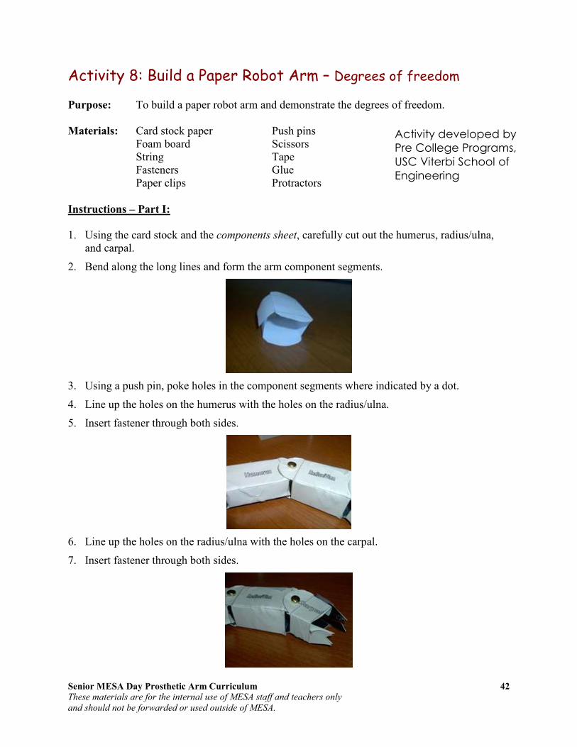
Senior MESA Day Prosthetic Arm Curriculum 42
These materials are for the internal use of MESA staff and teachers only
and should not be forwarded or used outside of MESA.
Activity 8: Build a Paper Robot Arm – Degrees of freedom
Purpose: To build a paper robot arm and demonstrate the degrees of freedom. Materials: Card stock paper Push pins Foam board Scissors String Tape Fasteners Glue Paper clips Protractors
Instructions – Part I:
1. Using the card stock and the components sheet, carefully cut out the humerus, radius/ulna,
and carpal.
2. Bend along the long lines and form the arm component segments.
3. Using a push pin, poke holes in the component segments where indicated by a dot.
4. Line up the holes on the humerus with the holes on the radius/ulna.
5. Insert fastener through both sides.
6. Line up the holes on the radius/ulna with the holes on the carpal.
7. Insert fastener through both sides.
Activity developed by
Pre College Programs,
USC Viterbi School of
Engineering

Senior MESA Day Prosthetic Arm Curriculum 43
These materials are for the internal use of MESA staff and teachers only
and should not be forwarded or used outside of MESA.
8. Cut a strip of foam board 4" x 2".
9. Cut another strip of foam board 3" x 2".
10. Cut two small pieces of foam board 1" x 2".
11. Create a standing post by gluing the two small pieces of foam board on each side of the 4"
foam board.
12. Glue the standing post in the center of the 3" foam board.
13. Tape free side of humerus to the top of the standing post.
14. Tape a string to the proximal end of the radius/ulna.
15. Insert a paper clip through the top of the standing post.
16. Bring the free end of the humerus string through the right side of the paper clip.
Questions for Analysis
• How many degrees of freedom does your paper robot arm possess?
• Using a protractor, determine the actual degrees of movement.
• Determine the angular displacement.
Side Front
Side Front
Senior MESA Day Prosthetic Arm Curriculum 44
These materials are for the internal use of MESA staff and teachers only
and should not be forwarded or used outside of MESA.
Instructions – Part II:
1. Using what you learned in Part I, design and create another paper robot arm that has three or
more degrees of freedom. You can modify the existing paper robot arm or you can create a new paper robot arm.
Questions for Analysis
• How many degrees of freedom does your new paper robot arm possess?
• Describe the degrees of freedom.
• Using a protractor, determine the actual degrees of each movement.
• Determine the angular displacement for each degree of freedom.
• What was different in the design of your new paper robot arm from the original one in Part I that allowed for additional degrees of freedom? Describe in detail the design differences.
Activity developed by Pre College Programs, USC Viterbi School of Engineering

Senior MESA Day Prosthetic Arm Curriculum 45
These materials are for the internal use of MESA staff and teachers only
and should not be forwarded or used outside of MESA.
Activity 8: Build a Paper Robot Arm Components Sheet
Activity developed by Pre College Programs, USC Viterbi School of Engineering

Senior MESA Day Prosthetic Arm Curriculum 46
These materials are for the internal use of MESA staff and teachers only
and should not be forwarded or used outside of MESA.
Kinetics Kinematics of human motion allows for a visualization of motion but does not give an understanding of why the motion is occurring. This requires the study of forces, kinetics. Whether a body segment is at rest or in motion depends on the forces exerted on that body (law
inertia).
Extrinsic (external) Forces
• Gravitation force is the pull of the earth on objects within its sphere of influence.
o Gravitation acceleration = g = 9.8 m/s2 = 32.2 ft/s
2
� Ignoring air resistance, an object falling freely near the Earth’s surface increase its velocity with 9.8 m/s for each second of its descent.
� According to Newton’s Third Law, the Earth itself experiences an equal and opposite force to that acting on the falling object, meaning that the Earth also accelerates towards the object (until the object hits the earth, then the Law of Conservation of Energy states that it will move back with the same acceleration with which it initially moved forward, cancelling out the two forces of gravity). However, because the mass of the Earth is huge, the acceleration of the Earth by this same force is negligible, when measured relative to the system’s center of mass.
• Fluid force can also exert a push and pull on the body segment.
o Examples include wind and water.
� Fluid forces include buoyancy, drag and lift.
• Contact forces also exert a push and pull.
o Examples include the push of the ground on the foot and the pull of a briefcase on the arm.
� Normal reaction force and friction force
Intrinsic (internal) Forces
• Internal forces include muscles (pull of the biceps brachii on the radius), ligaments (pull of a ligament on a bone), and bones (the push of one bone on another bone).
• Friction occurs between articular surfaces.
o Minimized by synovial fluid
• Tension of antagonistic muscles, ligament, fasciae, and capsules
• Atmospheric pressure within the joint capsule

Senior MESA Day Prosthetic Arm Curriculum 47
These materials are for the internal use of MESA staff and teachers only
and should not be forwarded or used outside of MESA.
Force Vectors
All forces are vector quantities and can be defined by:
• A point of application on the object being acted on
• An action line and direction indicating a pull toward the source or a push away from the source
• A magnitude (the quantity of force being exerted)
A vector is traditionally represented by a line segment with a definite direction, or graphically as an arrow, connecting an initial point A with a terminal point B, and expressed by
The magnitude or quantity of the vector is the length of the segment and the direction characterizes the displacement of B relative to A.
An example of a vector that depicts the force of a hand pushing a book is shown in the figure. The force called “hand on book” is represented by vector HB. The point of application is the location where the finger touches the book. The action line and direction indicate the direction of the push. The length of the segment is drawn to represent the magnitude of the push. The length of a vector is usually drawn proportional to the magnitude of the force using a specified scale. For instance, if the scale is given as 1 cm = 4 N, an arrow of 2 cm would represent 8 N. The action line of any vector can be considered infinitely long; any vector can be extended in determining relationships of the vector to other vectors or objects.
Force of Gravity
Gravity is the force of attraction between all masses in the universe; especially the attraction of the earth’s mass for the mass of other objects near its surface. The force of gravity gives an object weight, the magnitude of the force that must be applied to an object in order to support it (i.e. hold it at rest) in a gravitational field. Weight is defined as the mass of the object times the acceleration of gravity:
Weight = mass x 9.8 m/s2 or 32.2 ft/s
2
Gravity is the most consistent and predicable force encountered by the human body. Gravity is a vector quantity and can be defined by a point of application, action line and direction, and magnitude. Its point of application is given as the center of mass (also known as the center of gravity) of that object, the specific point at which the object’s mass behaves as if it were concentrated. If an object is uniform, the center of mass is located in the geometric center of the
A vector going from A to B
HB

Senior MESA Day Prosthetic Arm Curriculum 48
These materials are for the internal use of MESA staff and teachers only
and should not be forwarded or used outside of MESA.
object. In an object is irregular in shape, the center of mass will be located toward the heavier end where the mass will be evenly distributed around the point. When an object is supported
at its center of mass, there is no net torque (force acting on an object that causes that object
to rotate) acting on the body and it will remain in static equilibrium. Each segment of the body is acted on by the force of gravity and has its own center of mass. Two or more adjacent segments can be combined together to move as a single rigid segment. When segments are combined, the force of gravity acting on the joined segments can be represented by a single center of mass. Figure C shows the center of mass for the combined arm, considering the hand as a single rigid segment while figure A depicts the center of masses for the individual segments of the arm (GA), the forearm (GF), and the hand (GH). When two adjacent segments are combined and considered as one rigid segment, the new larger segment will have a center of mass
that is located between and in line with the original two centers of mass (see figure B). The new center of mass of the combined forearm and hand will have a magnitude equal to the sum of GF and GH. The center of mass for any object or rigid series of segments will remain unchanged regardless of the position of that object in space. However, when an object is composed of two or more linked and movable segments, the location of the center of mass of the combined unit will change if the segments are rearrange in relation to each other. Figure D depicts the arm segment and the forearm/hand segment being rearranged. The magnitude of the force of gravity will not change because the mass of the combined segments have not changed, but the point of application of the resultant force will be different.
Equilibrium
If all forces acting on a body are balanced, a state known as equilibrium, the body will remain at rest or in uniform motion. If the forces are not balances, the body will accelerate. Isaac Newton’s first two laws govern whether an object is at rest or in motion.
• Newton’s First Law of Motion – Law of Inertia: Every object persists in its state of rest or uniform motion in a straight line unless it is compelled to change that state by forces impressed on it.
- Inertia is the resistance an object has to change in its state of motion.
A. Gravity acting on the arm segment (GA), the forearm segment (GF), and the hand segment (GH). B. Gravity acting on the arm and forearm-hand segments (GFh). C. Gravity acting on the arm-forearm-hand segment (GAfh). D. The CoM of the arm-forearm-hand segment shifts when segments are rearranged. Image taken from Joint Structure and Function: A Comprehensive
Analysis, Levangie, and Norkin.

Senior MESA Day Prosthetic Arm Curriculum 49
These materials are for the internal use of MESA staff and teachers only
and should not be forwarded or used outside of MESA.
- An object at rest will remain at rest unless acted on by an unbalanced force. An object in motion continues in motion with the same speed and in the same direction unless acted upon by an unbalanced force.
- All objects resist changes in their state of motion. “Objects keep doing what they are doing.”
- For an object to be in equilibrium, the sum of all the forces applied to that object must be zero.
o ∑ F = 0
• Newton’s Second Law of Motion – Law of Acceleration: Pertains to the behavior of objects for which all existing forces are not balanced. Force is equal to the change in momentum (mV) per change in time. For a constant mass, force equals mass times acceleration. F = m * a
- The law defines a force to be equal to change in momentum (mass
times velocity) per change in time.
- Acceleration is produced when a force acts on a mass.
- The acceleration of an object as produced by a net force is directly proportional to the magnitude of the net force, in the same direction as the next force, and inversely proportional to the mass of the object.
o a = F / m
- A large unbalanced push or pull (force) applied to an object of a constant mass will produce more acceleration than a small push or pull.
- Acceleration may occur as a change in velocity of an object or as a change in direction.
- The greater the mass (of the object being accelerated) the greater amount of force needed (to accelerate the object). Heavier objects require more force to move the same distance as lighter objects.
- A net unbalanced force can produce translatory, rotatory, or general motion.
Reaction Forces
In order to understand the source and application of forces, a critical property of forces must be considered: forces always come in pairs – equal and opposite action-reaction force pairs.
• Newton’s Third Law of Motion – Law of Reaction: For every action, there is an equal and opposite reaction.
- For every force there is a reaction force that is equal in size,
but opposite in direction. Whenever an object pushes another object it gets pushed back in the opposite direction equally hard.
- When you push an object, it pushes back.

Senior MESA Day Prosthetic Arm Curriculum 50
These materials are for the internal use of MESA staff and teachers only
and should not be forwarded or used outside of MESA.
Additional Linear Forces
In understanding why the motion is occurring, additional linear forces such as tension, friction, shear, and torque need to be examined. Tension is the pulling force exerted when an object is being stretched or elongated. Tension in the joint capsule, just like tension in any passive structure such as the bone, is created by opposite pulls on the object.
• Tensile forces (or the resultants of tensile forces) on an object are always equal in magnitude, opposite in direction, and applied parallel to the long axis of the object.
• Tensile forces are co-linear, coplanar, and applied to the same object; therefore, tensile vectors are part of the same linear force system.
• Tensile forces applied to a flexible or rigid structure of homogeneous composition create the same tension at all points along the long axis of the structure in the absence of friction; that is, tensile forces are transmitted along the length (long axis) of the object.
Compression is the force applied to an object tending to cause a decrease in volume. When two segments of a joint are pushed together, the resulting reaction forces are referred to as joint reaction forces. Joint reaction forces are contact forces that result whenever two or more forces cause contact between contiguous joint surfaces. The two forces that cause joint reactions forces are known as compression forces which are required to push joint surfaces together.
• Joint compression forces create contact between joint surfaces.
• There must be a minimum of one (or one resultant) compression force on each contiguous joint segment, with each compression force perpendicular to and directed toward the segment’s joint surface, and opposite in direction to the compression force on the adjacent segment.
A force (regardless of its source) that moves or attempts to move one object on another is known as a shear force. A friction force potentially exists on an object whenever there is a contact force on that object. For friction to have magnitude, some other force (a shear force) must be moving or attempting to move one or both of the contacting objects on each other.
The tensile forces of legfoot-on-capsule (LfC) and femur-
on-capsule (FC)
Image taken from Joint Structures and Function
Joint compression results in joint reaction forces (FLf and LFf) when there is a net compression force applied to each of the adjacent joint segments (dashed vectors) toward the joint surfaces Image taken from Joint Structures and Function
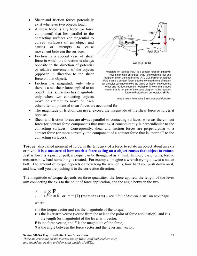
Senior MESA Day Prosthetic Arm Curriculum 51
These materials are for the internal use of MESA staff and teachers only
and should not be forwarded or used outside of MESA.
• Shear and friction forces potentially exist whenever two objects touch.
• A shear force is any force (or force component) that lies parallel to the contacting surfaces (or tangential to curved surfaces) of an object and causes or attempts to cause movement between the surfaces.
• Friction is a special case of shear force in which the direction is always opposite to the direction of potential or relative movement of the objects (opposite in direction to the shear force on that object).
• Friction has magnitude only when there is a net shear force applied to an object; this is, friction has magnitude only when two contacting objects move or attempt to move on each other after all potential shear forces are accounted for.
• The magnitude of friction can never exceed the magnitude of the shear force or forces it opposes.
• Shear and friction forces are always parallel to contacting surfaces, whereas the contact force (or contact force component) that must exist concomitantly is perpendicular to the contacting surfaces. Consequently, shear and friction forces are perpendicular to a contact force (or more correctly, the component of a contact force that is “normal” to the contacting surfaces).
Torque, also called moment of force, is the tendency of a force to rotate an object about an axis or pivot; it is a measure of how much a force acting on a object causes that object to rotate. Just as force is a push or pull, a torque can be thought of as a twist. In more basic terms, torque measures how hard something is rotated. For example, imagine a wrench trying to twist a nut or bolt. The amount of torque depends on how long the wrench is, how hard you push down on it, and how well you are pushing it in the correction direction. The magnitude of torque depends on three quantities: the force applied, the length of the lever arm connecting the axis to the point of force application, and the angle between the two.
or τ = (F) (moment arm) – see “Joint Moment Arm” on next page
where
τ is the torque vector and τ is the magnitude of the torque, r is the lever arm vector (vector from the axis to the point of force application), and r is
the length (or magnitude) of the lever arm vector, F is the force vector, and F is the magnitude of the force, θ is the angle between the force vector and the lever arm vector.
Footplate-on-legfoot (FpLf) is a contact force (FC) that will result in friction-on-legfoot (FrLf) between the foot and
footplate, given the shear force (FS), GLf. Femur-on-legfoot (FLf) is also a contact force, but the low coefficient of friction for articular cartilage makes the value of friction between the
femur and leg-foot segment negligible. Shown in a shaded vector that is not part of the space diagram is the reaction
force to FrLf, friction-on-footplate (FrFp).
Image taken from Joint Structures and Function

Senior MESA Day Prosthetic Arm Curriculum 52
These materials are for the internal use of MESA staff and teachers only
and should not be forwarded or used outside of MESA.
Joint Moment Arm
Although muscles produce linear forces, motions at joints are all rotary. The rotary torque
is the product of the linear force and the moment arm or mechanical advantage of the
muscle about the joint's center of rotation. Mechanically, this is the distance from the muscle's line of action to the joint's center of rotation. Determination of joint moment arm requires an understanding of the anatomy and movement (kinematics) of the joint of interest. For example, some joints can be considered to rotate about a fixed point. A good example of such a joint is the elbow. At the elbow joint, where the humerus and ulna articulate, the resulting rotation occurs primarily about a fixed point, referred to as the center of rotation. In the case of the elbow joint, this center of rotation is relatively constant throughout the joint range of motion. However, in other joints (for example the knee) the center of rotation moves in space as the knee joint rotates because the articulating surfaces are not perfect circles. In the case of the knee, it is not appropriate to discuss a single center of rotation--rather we must speak of a center of rotation corresponding to a particular joint angle, or, using the terminology of joint kinematics, we must speak of the instant center of rotation (ICR), that is, the center of rotation at any "instant" in time or space. Having defined a joint ICR, the moment arm is
defined as the perpendicular distance from line
of force application to the axis of rotation (the perpendicular distance between forces that produce a torque).
Moment Arm = ⊥d⊥d⊥d⊥d
This is illustrated for a simulated elbow joint. In A, the elbow joint is almost fully extended. Let the angle, q, between the brachialis muscle and the ulna be relatively small, e.g., q=20°. Let the distance between the brachialis insertion site and the elbow instant center be 5 cm. In this case, the perpendicular distance between the line of force application and the elbow ICR is shown by the dotted line in A and is equivalent to 5 cm x sin(20°) = 1.7 cm. Thus because the joint is nearly fully extended, this presents an unfavorable mechanical advantage to the muscle--the moment arm is relatively small. Much of the force generated by the muscle will simply compress the joint, not rotate it. Contrast this situation with the conditions shown in B, where the joint has now been flexed so that q=50°. Now, the moment arm equals 5 cm x sin(50°) = 4.3 cm. We see that for a simple hinge joint (a joint with a fixed ICR), the maximum moment arm is attained at q=90°. If we plotted moment arm vs. joint angle for this simple hinge joint, we would obtain a simple sine function that has a maximum of 5 cm occurring at q=90°. Such a curve can be generated for any joint. In general, the experimental curves are not quite as simple as the one here.
• As the angle of application of a force increase, the moment arm of the force increases.
• As the moment arm of a force increase, its potential to produce torque increases.
• The moment arm of a force is maximal when the force is applied at 90° to its segment.
• The moment arm of a force is minimal (0.0) when the action line of the force passes through the center of rotation of the segment to which the force is applied.

Senior MESA Day Prosthetic Arm Curriculum 53
These materials are for the internal use of MESA staff and teachers only
and should not be forwarded or used outside of MESA.
Classes of Levers
One way used to assess the relative torques of internal and external forces is that of classes of levers. A lever is any rigid segment that rotates around a pivot point, called the fulcrum, or an axis of rotation. A lever system exists whenever two forces are applied to a lever in a way that produces opposing torques. There are three classes of levers representing variations in the location of the fulcrum and opposing forces.
First-class levers
A first-class lever is a lever in which the fulcrum is located in between the input (effort) force and the output (resistance) force. The effort force and the resistance force are located on opposite sides of axis of rotation. In operation, a force is applied (by pulling or pushing) to a section of the bar, which causes the lever to swing about the fulcrum, overcoming the resistance force on the opposite side. The fulcrum is the center of the lever on which the bar (as in a seesaw) lays upon. The human body has relatively few first-class levers.
Resistance/Output Force : Axis/Pivot : Effort/Input Force
Examples include: 1. Seesaw (also known as a teeter-totter) 2. Crowbar (curved end of it) 3. Trebuchet uses a heavy counterweight to launch projectiles 4. Force of triceps muscle on the olecranon of the ulna (a large, thick, curved bony
eminence at the proximal end) in extension, creating a clockwise rotation and a resultant external force pushing up on the forearm in a counterclockwise direction
Second-class levers
In a second class lever the input (effort) force is located to at the end of the bar and the fulcrum is located at the other end of the bar, opposite to the input, with the output (resistance) force at a point between these two forces. The effort force and the resistance force are on the same side of the axis of rotation. The effort arm (EA) is GREATER than the resistance arm (RA) – see “Law of the Lever” on next page. In the human body, second-levers commonly occur when gravity is the effort force and muscles are the resistance. There are also examples in which the muscle is the effort muscle, but the distal segment to which the muscle is attached is weight bearing. The result is movement of the proximal rather than distal lever.
Effort/Input Force : Resistance/Output Force : Axis/Pivot

Senior MESA Day Prosthetic Arm Curriculum 54
These materials are for the internal use of MESA staff and teachers only
and should not be forwarded or used outside of MESA.
Examples include: 1. Stapler 2. Diving board (spring boar) 3. Nutcracker 4. Force of the brachioradialis muscle on the styloid process of the radius (the point of
attachment for the muscles at the distal end of the radius past the center of mass) in flexion
5. Action of the triceps surae (gastrocnemius, soleus, and plantaris) liftig the body around the axis of the toes (metatarsophalangeal joints) – standing on tip-toe.
Third-class levers
For this class of levers, the input (effort) force is higher than the output (resistance) force, which is different from second-class levers and some first-class levers. The input force is applied between the output force on one end and the fulcrum on the opposite end. The effort and resistance forces are on the same side of the axis of rotation. The effort arm (EA) is SMALLER than the resistance arm (RA) – see “Law of the Lever” below. Third class levers are common in the human body.
Resistance/Output Force: Effort/Input Force: Axis/Pivot
Examples include: 1. Boat paddle 2. Broom 3. Spoons (when used for flinging food. This uses your index finger as the fulcrum, your
thumb as the effort, and the load is the food.) 4. Biceps brachii performing flexion of the forearm/hand segment against the resistance of
gravity
Law of the Lever
The effort arm (EA) is the distance the effort force lies from the axis of rotation or the fulcrum/pivot point. The resistance arm (RA) is the distance the resistance force lies from the axis of rotation or the fulcrum/pivot point. The Law of the Lever is:
Effort Arm x Effort Force =
Resistance Arm x Resistance Force
A 120 lb boy 3 feet from the axis of rotation or fulcrum balances his 80 lb sister 4.5 feet from the axis of rotation or fulcrum.
3 x 120 = 4.5 x 80
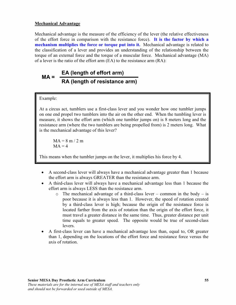
Senior MESA Day Prosthetic Arm Curriculum 55
These materials are for the internal use of MESA staff and teachers only
and should not be forwarded or used outside of MESA.
Mechanical Advantage
Mechanical advantage is the measure of the efficiency of the lever (the relative effectiveness of the effort force in comparison with the resistance force). It is the factor by which a
mechanism multiplies the force or torque put into it. Mechanical advantage is related to the classification of a lever and provides an understanding of the relationship between the torque of an external force and the torque of a muscular force. Mechanical advantage (MA) of a lever is the ratio of the effort arm (EA) to the resistance arm (RA):
MA =
• A second-class lever will always have a mechanical advantage greater than 1 because the effort arm is always GREATER than the resistance arm.
• A third-class lever will always have a mechanical advantage less than 1 because the effort arm is always LESS than the resistance arm.
o The mechanical advantage of a third-class lever – common in the body – is poor because it is always less than 1. However, the speed of rotation created by a third-class lever is high; because the origin of the resistance force is located farther from the axis of rotation than the origin of the effort force, it must travel a greater distance in the same time. Thus, greater distance per unit time equals to greater speed. The opposite would be true of second-class levers.
• A first-class lever can have a mechanical advantage less than, equal to, OR greater than 1, depending on the locations of the effort force and resistance force versus the axis of rotation.
Example: At a circus act, tumblers use a first-class lever and you wonder how one tumbler jumps on one end propel two tumblers into the air on the other end. When the tumbling lever is measure, it shows the effort arm (which one tumbler jumps on) is 8 meters long and the resistance arm (where the two tumblers are being propelled from) is 2 meters long. What is the mechanical advantage of this lever? MA = 8 m / 2 m MA = 4 This means when the tumbler jumps on the lever, it multiplies his force by 4.
EA (length of effort arm)
RA (length of resistance arm)

Senior MESA Day Prosthetic Arm Curriculum 56
These materials are for the internal use of MESA staff and teachers only
and should not be forwarded or used outside of MESA.
Activity 9: Physics Review
The Physics Classroom, a high school physics tutorial
1. Go to the following website http://www.physicsclassroom.com/Class/index.cfm.
2. Review each of the lessons listed below:
One Dimensional Kinematics
Lesson 1: Describing Motion with Words Lesson 2: Describing Motion with Diagrams Lesson 3: Describing Motion with Position vs. Time Graphs Lesson 4: Describing Motion with Velocity vs. Time Graphs Lesson 5: Free Fall and Acceleration of Gravity
Newton’s Laws
Lesson 1: Newton’s First Law of Motion Lesson 2: Force and Its Representation Lesson 3: Newton’s Second Law of Motion Lesson 4: Newton’s Third Law of Motion
Vectors: Motion and Forces in Two Dimensions
Lesson 1: Vectors – Fundamentals and Operations Lesson 2: Projectile Motion Lesson 3: Forces in Two Dimensions
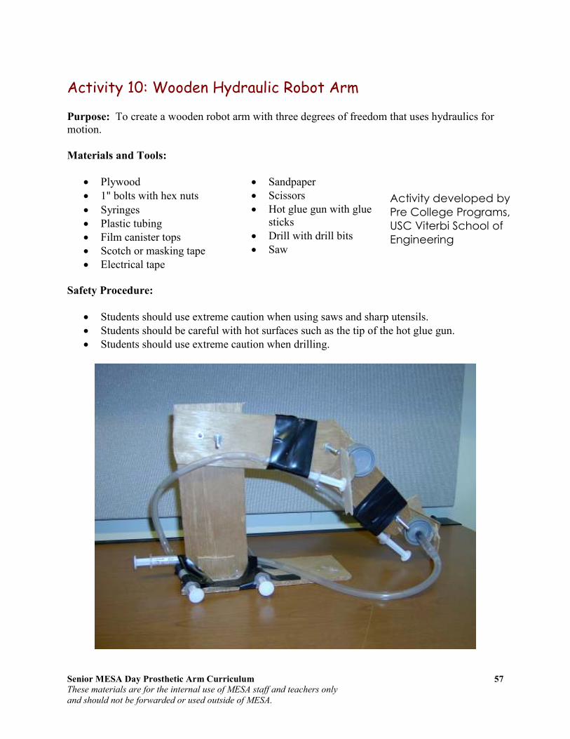
Senior MESA Day Prosthetic Arm Curriculum 57
These materials are for the internal use of MESA staff and teachers only
and should not be forwarded or used outside of MESA.
Activity 10: Wooden Hydraulic Robot Arm
Purpose: To create a wooden robot arm with three degrees of freedom that uses hydraulics for motion.
Materials and Tools:
• Plywood
• 1" bolts with hex nuts
• Syringes
• Plastic tubing
• Film canister tops
• Scotch or masking tape
• Electrical tape
• Sandpaper
• Scissors
• Hot glue gun with glue sticks
• Drill with drill bits
• Saw
Safety Procedure:
• Students should use extreme caution when using saws and sharp utensils.
• Students should be careful with hot surfaces such as the tip of the hot glue gun.
• Students should use extreme caution when drilling.
Activity developed by
Pre College Programs,
USC Viterbi School of
Engineering

Senior MESA Day Prosthetic Arm Curriculum 58
These materials are for the internal use of MESA staff and teachers only
and should not be forwarded or used outside of MESA.
Instructions:
1. Cut two 6" x 3" plywood long rectangles.
2. Cut a 4" x 2 ½" plywood medium rectangle.
3. Cut a 2 ½" x 2 ½" plywood square.
4. Round off the corners of each piece by sanding with sandpaper.
5. In the middle of one of the long rectangles, drill three holes – diameter of bolt – (1" and 2" from one end and another hole ½" from the other end). This is the humerus.
6. In the middle of the other long rectangle, drill two holes – diameter of bolt – (½" from each end). This is the radius/ulna.
7. In the middle of the medium rectangle, drill one hole – diameter of bolt – ½" from one end. This is the carpal.
8. Using a ½" drill bit, drill a hole in the middle and center of the carpal.
9. Line up the single hole from the humerus with a hole on the radius/ulna. Insert a bolt through both holes and tighten nut while still allowing radius/ulna to move.
10. Line up the remaining hole from the radius/ulna with the small hole on the carpal and insert bolt through both holes and tighten nut while still allowing carpal to move.
Standing Post
11. Cut a strip of plywood 10" x 3".
12. Cut two small pieces of plywood 1" x 3".
13. On the 10" x 3" plywood, drill a hole 1" from the top and ½" from one of the sides (this side will be the back of the standing post). Drill another hole 1" to the right.
14. Create the standing post by gluing the two small pieces (1" x 3") of plywood on both bottom sides of the 10" x 3" plywood (the opposite end of the two holes).
15. Line up the holes on the standing post with the holes on the humerus. Insert bolts through holes and tighten nuts.
Platform
16. Using the center of mass, determine the dimensions of the platform in order to balance the standing post and the arm structures (humerus, radius/ulna, and carpal) with nuts and bolts.
Dimensions of platform = x
Humerus
Radius/ulna
Carpal
Standing Post

Senior MESA Day Prosthetic Arm Curriculum 59
These materials are for the internal use of MESA staff and teachers only
and should not be forwarded or used outside of MESA.
17. Cut a strip of plywood to the determined dimensions above.
18. Glue the standing post with humerus, radius/ulna, and carpal vertically in the center to one end of the platform.
Three Degrees of Freedom
19. Now, determine the best manner in attaching the syringes, plastic tubing, and film canister tops in order to create three degrees of freedom, taking into consideration center of mass, torque, and classes of levers. You may use additional materials if needed.
Questions for Analysis
• Calculate the work done by lifting a 147.87 ml (5 oz) Dixie cup filled with 100 ml of water to a height of 10 cm. Hint:
o Calculate the torque using the above parameters. Hint: use
• What class of lever is the wooden hydraulic robot arm? Why? What are the advantages and disadvantages of this class of lever?
Activity developed by Pre College Programs, USC Viterbi School of Engineering

Senior MESA Day Prosthetic Arm Curriculum 60
These materials are for the internal use of MESA staff and teachers only
and should not be forwarded or used outside of MESA.
Section V: Prosthetic Arm
Artificial Limbs An artificial limb is a type of prosthesis, an artificial substitute, that replaces a missing extremity such as arms or legs. The type of artificial limb used is determined largely by the extent of an amputation or loss and location of the missing extremity. Artificial limbs may be needed for a variety of reasons, including disease, accidents, and congenital defects. A congenital defect can create the need for an artificial limb when a person is born with a missing or damaged limb. Industrial, vehicular, and war related accidents are the leading cause of amputations in developing areas, such as large portions of Africa. In more developed areas, such as North America and Europe, disease is the leading cause of amputations. Cancer, infection and circulatory disease are the leading diseases that may lead to amputation.
History
The first specimen discovered archaeologically, known as the Roman Capua Leg, was found in a tomb in Capua, Italy, dating to 300 BC, and was made of copper and wood. Two artificial toes found on Egyptian mummies are even older, dating to 1295–664 BC; these are being tested (as of July 2007) to determine whether they could have been used in life. Armorers in the 15th and 16th centuries made artificial limbs out of iron for soldiers who lost limbs. Over the next several centuries, craftsmen began to develop artificial limbs from wood instead of metal because of the lighter weight of the material. In the 19th century, limbs became more widespread due to the large number of amputees from wars such as the Napoleonic Wars in Europe and the American Civil War. An artificial leg designed by London’s James Potts in 1800 and patented in 1805 became known as the Anglesey Leg. The prosthetic was
named after the Marquess of Anglesey who had lost his leg at Waterloo. James Potts fitted his prosthetic leg consisting of a wooden shaft and socket, steel knee joint, and an articulated foot with artificial cords or catgut tendons that connected knee flexion with foot flexion. The Anglesey Leg technology was brought to the United States in 1839 and became known as the American Leg. During the American Civil War, a Confederate soldier, J.E. Hanger, who had himself suffered the war's first amputation founded what was for a time the world's largest artificial limb factory.
The iron prosthetic hand worn by Götz von Berlichingen from 1508
Wooden leg of Gen. Józef Sowiński; from early 19th century
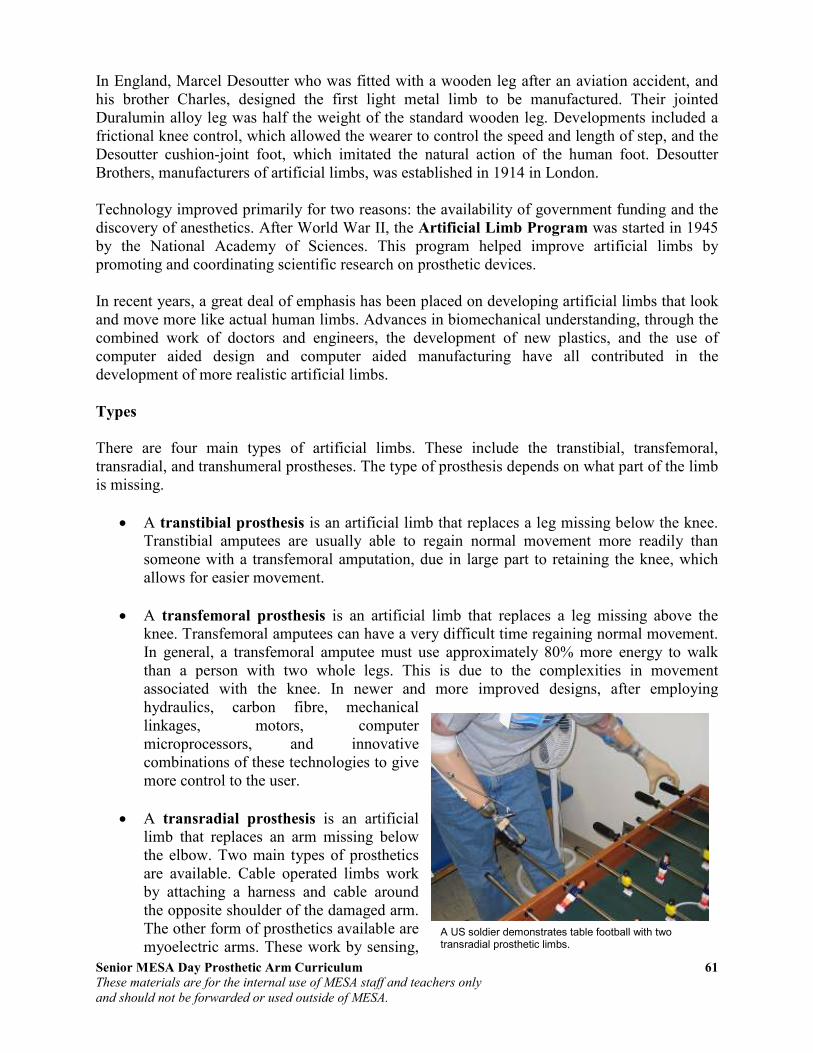
Senior MESA Day Prosthetic Arm Curriculum 61
These materials are for the internal use of MESA staff and teachers only
and should not be forwarded or used outside of MESA.
In England, Marcel Desoutter who was fitted with a wooden leg after an aviation accident, and his brother Charles, designed the first light metal limb to be manufactured. Their jointed Duralumin alloy leg was half the weight of the standard wooden leg. Developments included a frictional knee control, which allowed the wearer to control the speed and length of step, and the Desoutter cushion-joint foot, which imitated the natural action of the human foot. Desoutter Brothers, manufacturers of artificial limbs, was established in 1914 in London. Technology improved primarily for two reasons: the availability of government funding and the discovery of anesthetics. After World War II, the Artificial Limb Program was started in 1945 by the National Academy of Sciences. This program helped improve artificial limbs by promoting and coordinating scientific research on prosthetic devices. In recent years, a great deal of emphasis has been placed on developing artificial limbs that look and move more like actual human limbs. Advances in biomechanical understanding, through the combined work of doctors and engineers, the development of new plastics, and the use of computer aided design and computer aided manufacturing have all contributed in the development of more realistic artificial limbs.
Types
There are four main types of artificial limbs. These include the transtibial, transfemoral, transradial, and transhumeral prostheses. The type of prosthesis depends on what part of the limb is missing.
• A transtibial prosthesis is an artificial limb that replaces a leg missing below the knee. Transtibial amputees are usually able to regain normal movement more readily than someone with a transfemoral amputation, due in large part to retaining the knee, which allows for easier movement.
• A transfemoral prosthesis is an artificial limb that replaces a leg missing above the knee. Transfemoral amputees can have a very difficult time regaining normal movement. In general, a transfemoral amputee must use approximately 80% more energy to walk than a person with two whole legs. This is due to the complexities in movement associated with the knee. In newer and more improved designs, after employing hydraulics, carbon fibre, mechanical linkages, motors, computer microprocessors, and innovative combinations of these technologies to give more control to the user.
• A transradial prosthesis is an artificial limb that replaces an arm missing below the elbow. Two main types of prosthetics are available. Cable operated limbs work by attaching a harness and cable around the opposite shoulder of the damaged arm. The other form of prosthetics available are myoelectric arms. These work by sensing,
A US soldier demonstrates table football with two transradial prosthetic limbs.

Senior MESA Day Prosthetic Arm Curriculum 62
These materials are for the internal use of MESA staff and teachers only
and should not be forwarded or used outside of MESA.
via electrodes, when the muscles in the upper arm moves, causing an artificial hand to open or close.
• A transhumeral prosthesis is an artificial limb that replaces an arm missing above the elbow. Transhumeral amputees experience some of the same problems as transfemoral amputees, due to the similar complexities associated with the movement of the elbow. This makes mimicking the correct motion with an artificial limb very difficult.
Current Technology/Manufacturing
In recent years there have been significant advancements in artificial limbs. New plastics and other materials, such as carbon fiber, have allowed artificial limbs to be stronger and lighter, limiting the amount of extra energy necessary to operate the limb. This is especially important for transfemoral amputees. Additional materials have allowed artificial limbs to look much more realistic, which is important to transradial and transhumeral amputees because they are more likely to have the artificial limb exposed. In addition to new materials, the use of electronics has become very common in artificial limbs. Myoelectric limbs, which control the limbs by converting muscle movements to electrical signals, have become much more common than cable operated limbs. Myoelectric limbs allow the amputees to more directly control the artificial limb. Computers are also used extensively in the manufacturing of limbs. Computer Aided Design and Computer Aided Manufacturing are often used to assist in the design and manufacture of artificial limbs. Most modern artificial limbs are attached to the stump of the amputee by belts and cuffs or by suction. The stump usually fits into a socket on the prosthetic. The socket is custom made to create a better fit between the leg and the artificial limb, which helps reduce wear on the stump. The custom socket is created by taking a plaster cast of the stump and then making a mold from the plaster cast. Newer methods include laser guided measuring which can be input directly to a computer allowing for a more sophisticated design. One of the biggest problems with the stump and socket attachment is that there is a large amount of rubbing between the stump and socket. This can be painful and can cause breakdown of tissue. Artificial limbs are typically manufactured using the following steps:
1. Measurement of the stump
2. Measurement of the body to determine the size required for the artificial limb
3. Creation of a model of the stump
4. Formation of thermoplastic sheet around the model of the stump – This is then used to test the fit of the prosthetic
5. Formation of permanent socket
6. Formation of plastic parts of the artificial limb – Different methods are used, including vacuum forming and injection molding
7. Creation of metal parts of the artificial limb using die casting
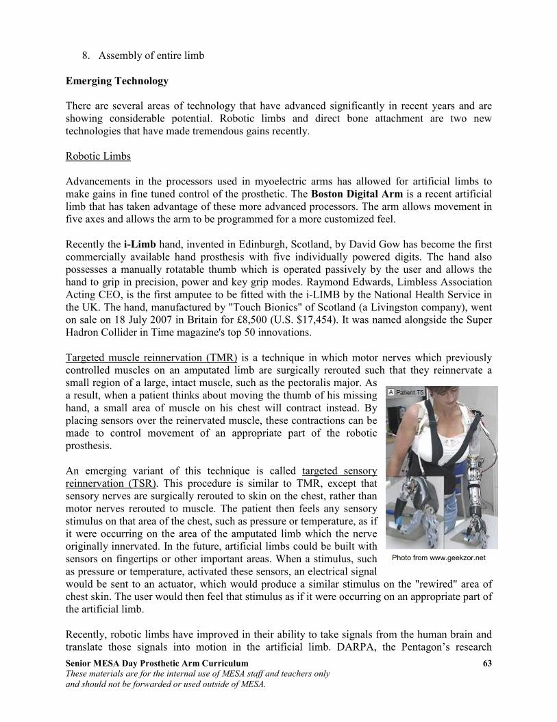
Senior MESA Day Prosthetic Arm Curriculum 63
These materials are for the internal use of MESA staff and teachers only
and should not be forwarded or used outside of MESA.
8. Assembly of entire limb
Emerging Technology
There are several areas of technology that have advanced significantly in recent years and are showing considerable potential. Robotic limbs and direct bone attachment are two new technologies that have made tremendous gains recently. Robotic Limbs Advancements in the processors used in myoelectric arms has allowed for artificial limbs to make gains in fine tuned control of the prosthetic. The Boston Digital Arm is a recent artificial limb that has taken advantage of these more advanced processors. The arm allows movement in five axes and allows the arm to be programmed for a more customized feel. Recently the i-Limb hand, invented in Edinburgh, Scotland, by David Gow has become the first commercially available hand prosthesis with five individually powered digits. The hand also possesses a manually rotatable thumb which is operated passively by the user and allows the hand to grip in precision, power and key grip modes. Raymond Edwards, Limbless Association Acting CEO, is the first amputee to be fitted with the i-LIMB by the National Health Service in the UK. The hand, manufactured by "Touch Bionics" of Scotland (a Livingston company), went on sale on 18 July 2007 in Britain for £8,500 (U.S. $17,454). It was named alongside the Super Hadron Collider in Time magazine's top 50 innovations. Targeted muscle reinnervation (TMR) is a technique in which motor nerves which previously controlled muscles on an amputated limb are surgically rerouted such that they reinnervate a small region of a large, intact muscle, such as the pectoralis major. As a result, when a patient thinks about moving the thumb of his missing hand, a small area of muscle on his chest will contract instead. By placing sensors over the reinervated muscle, these contractions can be made to control movement of an appropriate part of the robotic prosthesis. An emerging variant of this technique is called targeted sensory reinnervation (TSR). This procedure is similar to TMR, except that sensory nerves are surgically rerouted to skin on the chest, rather than motor nerves rerouted to muscle. The patient then feels any sensory stimulus on that area of the chest, such as pressure or temperature, as if it were occurring on the area of the amputated limb which the nerve originally innervated. In the future, artificial limbs could be built with sensors on fingertips or other important areas. When a stimulus, such as pressure or temperature, activated these sensors, an electrical signal would be sent to an actuator, which would produce a similar stimulus on the "rewired" area of chest skin. The user would then feel that stimulus as if it were occurring on an appropriate part of the artificial limb. Recently, robotic limbs have improved in their ability to take signals from the human brain and translate those signals into motion in the artificial limb. DARPA, the Pentagon’s research
Photo from www.geekzor.net
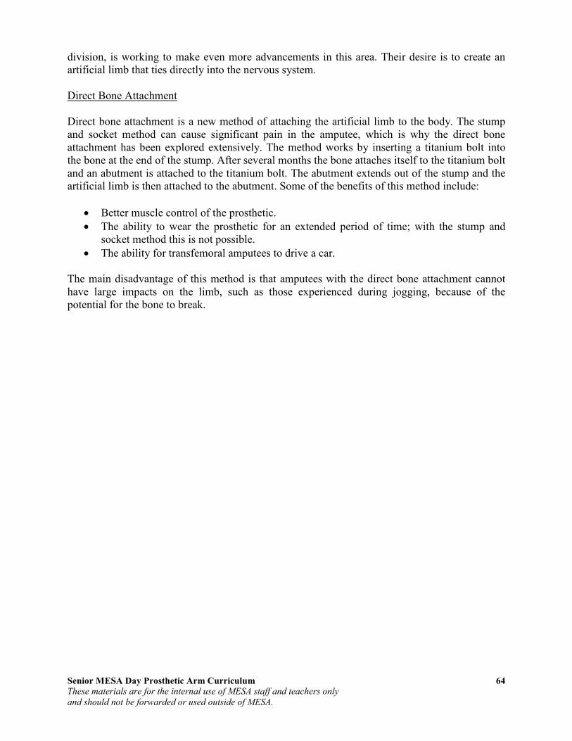
Senior MESA Day Prosthetic Arm Curriculum 64
These materials are for the internal use of MESA staff and teachers only
and should not be forwarded or used outside of MESA.
division, is working to make even more advancements in this area. Their desire is to create an artificial limb that ties directly into the nervous system. Direct Bone Attachment Direct bone attachment is a new method of attaching the artificial limb to the body. The stump and socket method can cause significant pain in the amputee, which is why the direct bone attachment has been explored extensively. The method works by inserting a titanium bolt into the bone at the end of the stump. After several months the bone attaches itself to the titanium bolt and an abutment is attached to the titanium bolt. The abutment extends out of the stump and the artificial limb is then attached to the abutment. Some of the benefits of this method include:
• Better muscle control of the prosthetic.
• The ability to wear the prosthetic for an extended period of time; with the stump and socket method this is not possible.
• The ability for transfemoral amputees to drive a car. The main disadvantage of this method is that amputees with the direct bone attachment cannot have large impacts on the limb, such as those experienced during jogging, because of the potential for the bone to break.

Senior MESA Day Prosthetic Arm Curriculum 65
These materials are for the internal use of MESA staff and teachers only
and should not be forwarded or used outside of MESA.
Activity 11: Build Your Own Robot Arm
Provided by TryEngineering - www.tryengineering.org Developed by IEEE as part of TryEngineering
www.tryengineering.org
Lesson Focus Develop a robot arm using common materials. Students will explore design, construction, teamwork,
and materials selection and use. Note: This lesson plan is designed for classroom use only, with supervision by
a teacher familiar with electrical and electronic concepts.
Lesson Synopsis Participating teams of three or four students are
provided with a bag including the materials listed below. Each team must use the materials to design and build a working robot arm. The robot arm must be at least
18 inches in length and be able to pick up an empty Styrofoam cup. Teams of students must agree on a design for the robot arm and identify what materials will be used. Students will draw a sketch of their agreed upon design prior to
construction. Resulting robot arms are then tested and checked for range of motion and satisfaction of the given criteria.
Objectives
• Learn design concepts. • Learn teamwork.
• Learn problem solving techniques. • Learn about simple machines.
Anticipated Learner Outcomes As a result of this activity, students should develop an understanding of:
• design concepts • teamwork needed in the design process • impact of technology in manufacturing
Lesson Activities Students design and build a working robotic arm from a set of everyday items with a goal of having the arm be able to pick up a Styrofoam cup. Working in teams of
three or four students, the students explore effective teamwork skills while learning simple robot mechanics.
Alignment to Curriculum Frameworks See attached curriculum alignment sheet.
Senior MESA Day Prosthetic Arm Curriculum 66
These materials are for the internal use of MESA staff and teachers only
and should not be forwarded or used outside of MESA.
Resources/Materials • 3" wide and approx. 22" long strips of cardboard -- 5 or so • Binder clips (different sizes) -- 8 or more • Brads -- @10
• Clothespins -- 6 • Craft sticks --10-15
• Fishing line -- 3-4 feet • Hangers -- 1 or 2 • Paper clips (diff. Sizes) -- 10-15
• Pencils -- 3-4 • Rubber bands (different sizes) --15
• Tape -- clear and masking (partial rolls should be fine) • Twine -- 3-4 feet • Various size scraps of cardboard --10 assorted
Internet Connections • TryEngineering (www.tryengineering.org) • Design Your Own Robot (www.mos.org/robot/robot.html)
• FIRST Robotics Competition (www.usfirst.org) • ITEA Standards for Technological Literacy: Content for the Study of
Technology
• (www.iteaconnect.org/TAA) • NSTA National Science Education Standards (www.nsta.org/standards)
• NCTM Principles and Standards for School Mathematics (http://standards.nctm.org)
• Robot Books (www.robotbooks.com)
Recommended Reading • Artificial Intelligence: Robotics and Machine Evolution by David Jefferis
(ISBN: 0778700461)
• Robotics, Mechatronics, and Artificial Intelligence: Experimental Circuit Blocks for Designers by Newton C. Braga (ISBN: 0750673893)
• Robot Builder's Sourcebook : Over 2,500 Sources for Robot Parts by Gordon
McComb (ISBN: 0071406859) • Robots (Fast Forward) by Mark Bergin (ISBN: 0531146162)
Optional Writing Activity • Write an essay (or paragraph depending on age) about how the invention of
robots and robotics has impacted manufacturing.
References Ralph D. Painter and other volunteers - Florida West Coast USA Section of IEEE
URL: http://ewh.ieee.org/r3/floridawc
Robot Arm
Developed by IEEE as part of TryEngineering
www.tryengineering.org

Senior MESA Day Prosthetic Arm Curriculum 67
These materials are for the internal use of MESA staff and teachers only
and should not be forwarded or used outside of MESA.
Build Your Own Robot Arm
For Teachers: Alignment to Curriculum Frameworks Note: All Lesson Plans in this series are aligned to the National Science Education Standards which were produced by the National Research Council and endorsed by
the National Science Teachers Association, and if applicable, also to the International Technology Education Association's Standards for Technological
Literacy or the National Council of Teachers of Mathematics' Principles and Standards for School Mathematics.
National Science Education Standards Grades 5-8 (ages 10 - 14) CONTENT STANDARD B: Physical Science
As a result of their activities, all students should develop an understanding of • Motions and forces • Transfer of energy
National Science Education Standards Grades 9-12 (ages 14 - 18) CONTENT STANDARD B: Physical Science As a result of their activities, all students should develop understanding of
• Motions and forces • Interactions of energy and matter
CONTENT STANDARD E: Science and Technology
As a result of activities, all students should develop • Abilities of technological design
• Understandings about science and technology
Standards for Technological Literacy - All Ages The Nature of Technology
• Standard 3: Students will develop an understanding of the relationships
among technologies and the connections between technology and other fields of study.
Technology and Society • Standard 7: Students will develop an understanding of the influence of
technology on history.
Design • Standard 9: Students will develop an understanding of engineering design.
• Standard 10: Students will develop an understanding of the role of troubleshooting, research and development, invention and innovation, and experimentation in problem solving.
Abilities for a Technological World • Standard 11: Students will develop abilities to apply the design process.
The Designed World • Standard 19: Students will develop an understanding of and be able to select
and use manufacturing technologies.
Robot Arm
Developed by IEEE as part of TryEngineering
www.tryengineering.org

Senior MESA Day Prosthetic Arm Curriculum 68
These materials are for the internal use of MESA staff and teachers only
and should not be forwarded or used outside of MESA.
Build Your Own Robot Arm For Teachers: Teacher Resources Divide your class into teams of three or four students, and provide student handout (attached). Students are then instructed to examine the materials provided (see list below) and to work as a team to design and build a robot arm out of the materials.
The robot arm must be at least 18 inches in length and be able to pick up an empty Styrofoam cup. Teams of students must agree on a design for the robot arm and
identify what materials will be used. Students should draw a sketch of their agreed upon design prior to construction.
Explain that teamwork, trial, and error are part of the design process. There is no "right" answer to the problem - each team's creativity will likely generate an arm
that is unique from the others designed in your class. Resources/Materials
• 3" wide and approx. 22" long strips of cardboard-- 5 or so • Binder clips (different sizes)-- 8 or more
• Brads-- @10 • Clothespins-- 6 • Craft sticks--10-15
• Fishing line-- 3-4 feet • Hangers-- 1 or 2
• Paper clips (diff. Sizes)-- 10-15 • Pencils-- 3-4 • Rubber bands (different sizes)--15
• Tape-- clear and masking (partial rolls should be fine)
• Twine-- 3-4 feet • Various size scraps of cardboard--10
assorted
Extension Ideas
"Humans and Robots," a NASA educational
brief which is attached, describes the robotics features on the International Space Station.
The brief's classroom activity is about making and using an ISS grapple fixture known as an end effector. The PDF file is also available at
http://spacelink.nasa.gov.
Robot Arm
Developed by IEEE as part of TryEngineering
www.tryengineering.org
Senior MESA Day Prosthetic Arm Curriculum 69
These materials are for the internal use of MESA staff and teachers only
and should not be forwarded or used outside of MESA.
Build Your Own Robot Arm
Student Worksheet :
How To Build Your Own Robot Arm You are a member of a team of three or four students, all working together to
design and build a robot arm out of the following materials which are provided to you. The robot arm must be at least 18 inches in length and be able to pick up an
empty Styrofoam cup. Your team must agree on a design for the robot arm and identify what materials will be used. Your team should draw a sketch of their agreed upon design prior to construction.
Part of the teamwork process is sharing ideas and determining which design your
team will go with. Trial and error are part of the design process. There is no "right" answer to the problem - your team's creativity will likely generate an arm that is unique from the others designed in your class.
Resources/Materials
• 3" wide and approx. 22" long strips of cardboard-- 5 or so
• Binder clips (different sizes)-- 8 or more • Brads-- @10 • Clothespins-- 6
• Craft sticks--10-15 • Fishing line-- 3-4 feet
• Hangers-- 1 or 2 • Paper clips (diff. Sizes)-- 10-15 • Pencils-- 3-4
• Rubber bands (different sizes)--15 • Tape-- clear and masking (partial rolls should be fine)
• Twine-- 3-4 feet • Various size scraps of cardboard--10 assorted
Robot Arm
Developed by IEEE as part of TryEngineering
www.tryengineering.org

Senior MESA Day Prosthetic Arm Curriculum 70
These materials are for the internal use of MESA staff and teachers only
and should not be forwarded or used outside of MESA.
Build Your Own Robot Arm
Student Worksheet: Robot Arm Exercise Questions
• Did you use all the materials provided to you? Why, or why not?
• Which item was most critical to your robot arm design?
• How did working as a team help in the design process?
• Were there any drawbacks to designing as a team?
• What did you learn from the designs developed by other teams?
• Name three industries that make use of robots in manufacturing:
Robot Arm
Developed by IEEE as part of TryEngineering
www.tryengineering.org
Senior MESA Day Prosthetic Arm Curriculum 71
These materials are for the internal use of MESA staff and teachers only
and should not be forwarded or used outside of MESA.
References Information for this curriculum was taken from the following websites:
• "Arm." Encyclopædia Britannica. 2009. Encyclopædia Britannica Online. 16 Jul. 2009 http://www.britannica.com/EBchecked/topic/35010/arm.
• Chai, Huei-Ming, Kinesiology. 2 January 2005. School of Physical Therapy, National Taiwan Univ. 13 July 2009. http://www.pt.ntu.edu.tw/hmchai/Kines04/KINoutline.htm.
• Eaton, Charles MD. E-Hand.com: The Electronic Textbook of Hand Surgery. The Hand Center. 15 July 2009. http://www.eatonhand.com/index.htm.
• Engineering Your Future. 29 July 2009. http://www.futuresinengineering.com/.
• Glenbrook South Physics Teachers. Glenbrook South Physics Home Page (curriculum and lessons). 22 July 2009. http://www.glenbrook.k12.il.us/GBSSCI/PHYS/phys.html.
• InnerBody: Guide to Human Anatomy Online. 10 July 2009. http://www.innerbody.com.
• Whitaker, Robert MD. Instant Anatomy. 10 July 2009. http://www.instantanatomy.net.
• Levangie, Pamela and Norkin, Cynthia. Joint Structure and Function: A Comprehensive
Analysis. 4th
Edition. Philadelphia, PA: F.A. Davis Company, 2005.
• National Skeletal Muscle Research Center, UC San Diego, http://muscle.ucsd.edu/NSMRC/home.shtml.
• Norman, Wesley, PhD, DSc. The Anatomy Lesson. 13 July 2009. http://home.comcast.net/~wnor/homepage.htm
• Ozkaya, Nihat and Nordin, Margareta. Fundamentals of Biomechanics: Equilibrium,
Motion, and Deformation. New York: Springer-Verlag, 1999.
• Pediatric Orthopaedics. 15 July 2009. http://www.pediatric-orthopedics.com/index.html
• The Physics Classroom. http://www.physicsclassroom.com
• Richards, Lorie and Loudon, Janice. Hand Kinesiology. University of Kansas Medical Center, school of Allied Health, Occupational and Physical Theraphy Education, http://classes.kumc.edu/sah/resources/handkines/kines2.html.
• Try Engineering. http://www.tryengineering.org.
• Understanding Arm Anatomy and Function. Healthline Network. http://www.healthline.com/hlbook/strt-understanding-arm-anatomy-and-function
• Wikipedia. http://en.wikipedia.org.
• Zhang, Yi, Introduction to Mechanisms. Carnegie Mellon University. http://www.cs.cmu.edu/~rapidproto/mechanisms/chpt4.html