Embed Size (px)
Citation preview
American Institute of Aeronautics and Astronautics
1
Propulsion Research and Academic Programs at the
University of Alabama in Huntsville
Robert A. Frederick, Jr.1 Phillip M. Ligrani2 and L. Dale Thomas3
UAH Propulsion Research Center, Huntsville, Alabama, 35899
The UAH Propulsion Research Center (PRC) is beginning its 26th year at the University of Alabama in
Huntsville (UAH). The mission of the Propulsion Research Center is to provide an environment that connects
the academic research community with the needs and concerns of the propulsion community while promoting
an interdisciplinary approach to solving propulsion problems. This paper describes highlights from the
research and academic programs associated with the center over the past eighteen months. Academic
highlights include the offering of new graduate courses in liquid rocket engineering and solid rocket
combustion instability. Research highlights include a new supersonic wind tunnel capability and a new
program in nuclear thermal propulsion systems engineering. In the 2016 fiscal year, total research
expenditures rose to $1.563 million and four Ph.D., eleven master’s students, and numerous undergraduate
students obtained degrees in conjunction with the center. The center continues to be a resource for both
fundamental and applied research as well as a significant contributor to workforce development in the
propulsion and energy field.
I. Introduction
HE Propulsion Research Center (PRC) celebrated its 25th year as a University of Alabama in Huntsville (UAH)
research organization in 2016. In 2005, Drs. Hawk and Frederick wrote a summary of the activities of the first
thirteen years of the UAH Propulsion Research Center.1 In 2016, Dr. Frederick wrote a summary of student graduation
rates, funded research programs, academic programs, and the laboratory capabilities that have developed over the first
twenty-five years of the PRC.2 This paper will highlight progress from the past eighteen months regarding the
academic and research programs of the UAH Propulsion Research Center.
1 Professor of Mechanical & Aerospace Engineering /Director of the Propulsion Research Center, Department of
Mechanical & Aerospace Engineering , 301 Sparkman Drive, Olin B. King Technology Hall, Room S226, Huntsville,
AL 35899, and AIAA Associate Fellow.
2 Professor of Mechanical & Aerospace Engineering /Eminent Scholar of Propulsion, Department of Mechanical
& Aerospace Engineering , 301 Sparkman Drive, Olin B. King Technology Hall, Room S236, Huntsville, AL 35899,
and AIAA Senior Member.
3 Professor of Industrial and Systems Engineering/Eminent Scholar of Systems Engineering, Department of
Industrial and Systems Engineering, 301 Sparkman Drive Olin B. King Technology Hall, Room N151, Huntsville,
AL 35899, and AIAA Senior Member.
T
American Institute of Aeronautics and Astronautics
2
PRC Mission and Strategy
The mission of the PRC is to provide an environment that
connects the academic research community with the needs and
concerns of the propulsion community, while promoting an
interdisciplinary approach to solving propulsion problems.
Collaborating individuals and groups are part of the PRC's
research goals. This mission is accomplished though
cooperation with researchers from government laboratories,
other universities, and the aerospace industry. The result of this
environment is leading-edge research and scholarly activity in
the pursuit of advanced technologies and their applications.
Overall Metrics
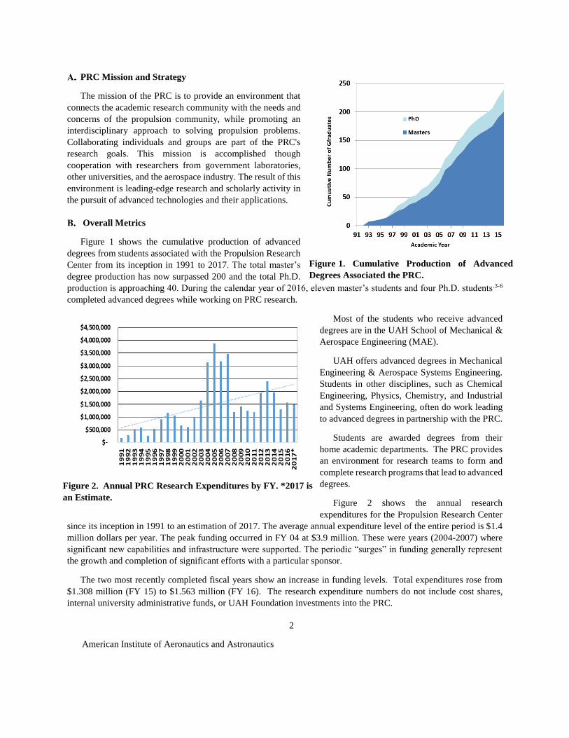
Figure 1 shows the cumulative production of advanced
degrees from students associated with the Propulsion Research
Center from its inception in 1991 to 2017. The total master’s
degree production has now surpassed 200 and the total Ph.D.
production is approaching 40. During the calendar year of 2016, eleven master’s students and four Ph.D. students.3-6
completed advanced degrees while working on PRC research.
Most of the students who receive advanced
degrees are in the UAH School of Mechanical &
Aerospace Engineering (MAE).
UAH offers advanced degrees in Mechanical
Engineering & Aerospace Systems Engineering.
Students in other disciplines, such as Chemical
Engineering, Physics, Chemistry, and Industrial
and Systems Engineering, often do work leading
to advanced degrees in partnership with the PRC.
Students are awarded degrees from their
home academic departments. The PRC provides
an environment for research teams to form and
complete research programs that lead to advanced
degrees.
Figure 2 shows the annual research
expenditures for the Propulsion Research Center
since its inception in 1991 to an estimation of 2017. The average annual expenditure level of the entire period is $1.4
million dollars per year. The peak funding occurred in FY 04 at $3.9 million. These were years (2004-2007) where
significant new capabilities and infrastructure were supported. The periodic “surges” in funding generally represent
the growth and completion of significant efforts with a particular sponsor.
The two most recently completed fiscal years show an increase in funding levels. Total expenditures rose from
$1.308 million (FY 15) to $1.563 million (FY 16). The research expenditure numbers do not include cost shares,
internal university administrative funds, or UAH Foundation investments into the PRC.
Figure 1. Cumulative Production of Advanced
Degrees Associated the PRC.
Figure 2. Annual PRC Research Expenditures by FY. *2017 is
an Estimate.

American Institute of Aeronautics and Astronautics
3
Figure 3. Distribution of Research Expedintures by Sponsor from Oct. 2014-July 2017
Current Research Programs
This section highlights the sponsors and levels of funding from FY 15 to the present. Figure 3 shows the cumulative
expenditures distributed over twenty-one sponsoring agencies for this time period. The Missile Defense Agency
(MDA) work performed by the PRC involves independent assessment of propulsion and energy technologies and the
work supports a multi-disciplinary team of faculty, staff, and graduate students. MDA is currently our “anchor tenant”
and provides over 50% of the funds expended. The other twenty projects involve state agencies, NASA, aerospace
companies, small businesses, and private companies. In FY 16, two new sponsors funded research at the PRC: Solar
Turbines, Inc. in the area of air breathing engines, at an anticipated total level of $966,668 from Oct. 2017 to 2022,
and Manufacturing Technical Solutions, Inc. (MTS) in the area of Nuclear Thermal Propulsion System Studies.
Example research program highlights are summarized in later Section III of this paper.
II. Academic Infrastructure
Mechanical & Aerospace Engineering
The Department of Mechanical & Aerospace Engineering provides the majority of the faculty and students that
participate in PRC research activities. The MAE Department offers Bachelors of Science Programs in Aerospace
Engineering & Mechanical Engineering accredited by the Accreditation Board for Engineering and Technology, Inc.

American Institute of Aeronautics and Astronautics
4
(ABET). At the graduate level, the MAE department offers Master’s and Ph.D. Programs in Aerospace Systems
Engineering & Mechanical Engineering.
The mission of the UAH Department of Mechanical & Aerospace Engineering (MAE) is to provide undergraduate and graduate
education, research, and public service in the Mechanical & Aerospace Engineering disciplines and to support the Mechanical
& Aerospace Engineering needs of Huntsville, the State of Alabama, the region, our nation, and the international community.4
The undergraduate program had a remarkable growth rate last year, expanding from 950 undergraduates in
academic year (AY) 15-16 to 1,068 in AY 16-17 with an anticipated 1,200 students in the fall of 2017. The Aerospace
portion at the undergraduate level has concurrently grown from about one-third to one-half of the undergraduate
population. The graduate program decreased from 170 students in AY 15-16 to 150 students in AY 16-17. This
decline comes in part from a decrease in part-time students alongside a relative increase in full-time students.
The MAE Department added two new tenure-track faculty in AY 15-116, bringing the total to twenty tenured and
tenure-track faculty; the first new faculty member is in the area of spacecraft dynamics and the second is in the area
of advanced power systems. The MAE department also added one lecturer in AY 15-16, bringing the total to five
full-time lecturers to assist with the growing undergraduate population. Several part-time instructors also help carry
the teaching load for the department.
Propulsion-Related Courses
Table 1 shows several propulsion-related classes
offered at UAH. The dual-level courses allow
undergraduate and graduate students to learn together.
Undergraduates at UAH can also participate in a Joint
Undergraduate Master’s Program (JUMP) in which they
can earn both undergraduate and graduate credit for taking
dual-level classes.
In the summer of 2016, the PRC combined resources
with the UAH College of Engineering and the UAH
College of Professional and Continuing Studies to offer
two new courses in Aerospace Engineering (Propulsion):
MAE 695 – Solid Rocket Combustion Instability and
MAE 695 – Liquid Rocket Engineering. Thirty-five UAH
graduate engineering students and fifteen professional
development students participated in the lectures.
Professional development students from South Africa,
Europe, and Canada, as well as students employed by
NASA and John Hopkins University, participated in the
courses.
The lectures were completed in a five-day intensive
format with professional development and graduate
4 http://www.uah.edu/eng/departments/mae/mission-statement
Table 1. UAH Undergraduate and Graduate (Dual Level)
Academic Courses Related to Propulsion and Energy

American Institute of Aeronautics and Astronautics
5
students present for all classroom lectures. The UAH graduate engineering students then completed additional
academic requirements for the courses by meeting for an additional three weeks with an instructor. The lectures from
these courses were recorded and are currently offered online for professional development credit as part of a
Professional Certificate Programs in Rocket Propulsion.
These new offerings increase UAH’s presence as a national leader in aerospace engineering, professional
development, and graduate education in propulsion-related engineering topics.
III. Research Highlights
Figure 4 shows the current PRC organization chart. Each box represents a functional area in the organization.
Currently, there are over 100 faculty, staff, and students associated with PRC research activities. The overall activities
are managed by a director who is supported by staff that manage fiscal programs, advise in technical matters, and
oversee laboratory operations. The bottom row of the organization chart shows seven topic areas from Energy and
Power Systems to Propulsion Systems Technology Test-bed. Each of these areas has a lead contact. The names
beneath these boxes show participating faculty and staff, graduates students, and undergraduates students who are
active in each area.
This past year, Dr. L. Dale Thomas was appointed as the Deputy Director of the Propulsion Research Center. He
has over thirty years of systems engineering and propulsion experience at NASA. Dr. Thomas is leading propulsion
Figure 4. The PRC Organization Chart.

American Institute of Aeronautics and Astronautics
6
systems engineering research and strategic planning activities. He joined UAH in 2015 and was named the Eminent
Scholar in Systems Engineering and a Professor of Industrial and Systems Engineering.
The next sections will briefly describe some of the current activities and capabilities and are presented using the
areas shown in the organizational chart.
Propulsion and Systems Integration
The mission of the UAH Propulsion Research Center is the advancement of basic science and technology
development related to propulsion and energy. These advances, while in and of themselves constituting complex and
challenging endeavors, are not ends unto themselves. Success in propulsion research is ultimately characterized by
infusion of a scientific principle or a matured technology into a system. A NASA internal study found that technology
infusion challenges (not technology readiness challenges) most often hinder successful application of advanced
technologies in NASA mission systems.7 These challenges most often take the form of integration roadblocks at the
architectural or system level.8 NASA recognizes the criticality of integration roadblocks as evidenced by the following
excerpt from the 2015 NASA Technology Roadmap:
Recent experiences with deep-space systems have highlighted cost growth issues during integration, testing, and operations.
These include changes to the design late in the life cycle, often resulting in a ripple effect of additional changes in other
areas, unexpected results during testing due to unplanned interaction of fault responses, and operational limitations placed
on the spacecraft based on how the system was tested, in order to ‘fly-as-you-test.’ These issues cause cost and schedule
growth during system development.9
Efforts are underway at the PRC and Complex System Integration Lab (CSIL), shown in Fig. 5, to apply Model
Based Systems Engineering (MBSE) to advanced propulsion systems integration as a method to address the propulsion
technology infusion problem.
Figure 5. Complex System Integration Lab (CSIL).
A Nuclear Thermal Propulsion (NTP) space transportation vehicle for human exploration beyond cislunar space
is the subject of one study. Although the fundamentals of NTP are well understood and ground test data exist from
the Nuclear Engine for Rocket Vehicle Application (NERVA) program in the 1960s, it has never been used in a
spaceflight vehicle, nor have any vehicle designs gone beyond the conceptual stage. The Systems Modeling Language
(SysML) is employed for this modeling effort to develop an integrated systems model that captures both the structure
and behavior of a NTP spaceflight vehicle. The baseline case under consideration is a hot bleed cycle type engine for
a mission architecture to Mars employing transfer orbits faster than Hohmann Transfers. In addition to providing an

American Institute of Aeronautics and Astronautics
7
integrated system model of a point design, mathematical models enable derivation of scaling relationships between
the NTP system, the flight vehicle, and the orbital mechanics driven by the destination and mission duration.19 The
model, depicted in Fig. 6 and 7, allows elements to be added or replaced as necessary to change the model for increased
fidelity calculations or to add new capabilities, such as electricity generation from the nuclear reactor or liquid oxygen
augmented thrust. This allows the integrated systems model to start very simple and grow to the requisite complexity.
Along the way, MBSE provides the very significant benefit of mutually consistent requirements, system design, and
concept of operations – an important consideration in the pre-conceptual studies portion of a life cycle when myriad
mission concepts and system trade studies can and typically does lead to gaps and conflicts.10
The NTP project serves as a pathfinder for propulsion systems integration utilizing advanced propulsion
technologies. For a successful propulsion system development, decisions need to be informed concerning the
engineering considerations at both the integrated engine and vehicle level, as the optimal choice at the engine
component level may be suboptimal at the integrated level, and in turn differ again at the integrated vehicle level. The
focus of this research is to apply MBSE to develop systems engineering models for the engine components, the engine,
and vehicle, providing specifications and sensitivities of alternatives to enable determination of an optimal vehicle
configuration for a given mission. The advanced propulsion systems integration tools and techniques developed and
analyses performed in this research will allow propulsion systems to be realized which incorporate new scientific
principles and technologies, and realized more quickly, economically, and reliably at lower risk
Figure 6. NTR Transfer Vehicle block from the model10 pictured next to the NTP powered crew and cargo
vehicles from NASA DRA 5.19

American Institute of Aeronautics and Astronautics
8
Figure 7. NTR Transfer Vehicle Hierarchy on NTR Block Definition Diagram.19Error! Bookmark
not defined.
Propulsion Laboratories
The PRC makes extensive use of laboratories for research programs. Several laboratories are administered and
maintained by the PRC at the Propulsion Test Facility the Johnson Research Center, and at other locations around the
UAH Campus. PRC-affiliated faculty also complete research projects in their own laboratories on campus and on
Redstone Arsenal.
Table 2 is a listing of these laboratories. This year, several upgrades and additions should be noted. The Propulsion
Test Facility is undergoing two major upgrades. The Hot Fire Rocket Test Cell is undergoing a $500,000 upgrade to
install a larger test stand, an altitude capability, and completely new data acquisition system; more details on this will
be reported next year when the work is complete. The Supersonic Wind Tunnel Facility is adding additional test
sections and several new large blow down tanks. The Mechanics of Materials under Extreme Conditions Laboratory
came online and recently won support to add new instrumentation. The description and use of several of these facilities
are described in the following sections.

American Institute of Aeronautics and Astronautics
9
Table 2. Laboratories Associated with PRC Research
Laboratory safety is always of paramount importance for all activities at the PRC. A five-year, external Process
Hazards Analysis (PHA) revalidation was performed on the PRC by Safety Management Services Inc. The PHA was
based on evaluation of PRC-provided information and onsite evaluations at UAH on January 24 – 25, 2017. The PHA
was tailored to meet requirements of OSHA 29 CFR 1910.119 “Process Safety Management of Highly Hazardous
Chemicals,” and the requirements outlined in DOD 4145.26-M “DOD Contractor’s Safety Manual for Ammunition
and Explosives.” Based on the type and complexity of the process, a Failure Modes and Effects Analysis (FMEA)
methodology was chosen for this effort. Where deficiencies existed, recommendations were issued to minimize or
eliminate the potential risk of identified failure scenarios. PRC leadership reviewed the recommendations and
appointed a team to make appropriate improvements and address items provided by this review.
Energy and Power Systems
1. Supersonic Flow and Shock Wave Interaction Investigations
This research activity is under the direction of Dr. Ligrani, and is sponsored by (a) the Alabama Innovation Fund
of Montgomery, Alabama, (b) the Office of the Vice President for Research and Economic Development of the
University of Alabama in Huntsville, Huntsville, Alabama, (c) Endowment Funds of the Eminent Scholar in
Propulsion of the University of Alabama in Huntsville, Huntsville, Alabama, and (d) the Arnold Engineering
Development Center of Arnold Air Force Base, Tullahoma, Tennessee.
Over the past eighteen months, efforts have been underway within the Propulsion Research Center to develop
capabilities to investigate supersonic flows, including topics related to shock wave interactions. To accomplish this
objective, four high pressure air storage tanks (donated from the Arnold Engineering and Development Center) have

American Institute of Aeronautics and Astronautics
10
been installed and mounted on a concrete pad. A low-pressure piping and valve system, including an air diverter
plenum, regulation valves, and safety devices, has been installed and is operational. The high-pressure valve and
piping system is being installed with completion expected by August of 2017. The design of the facility allows the
installation and use of three different test sections, installed in a parallel fashion. The supersonic test section includes
an inlet duct, supersonic nozzle, supersonic test section, exhaust plenum, instrumentation, and Schlieren flow
visualization system. The facility also includes a variety of flow management devices which are installed upstream of
the supersonic wind tunnel test section. With the present air supply, and low-pressure piping and valve arrangement,
inlet test section Mach numbers up to 3 can be achieved. Future configurations are expected to provide test section
Mach numbers as high as 5 or 6. The facility is designed with an inlet supply plenum and an exhaust plenum, just
upstream and downstream of the test section, in order to minimize the flow fluctuations and unsteadiness which could
propagate from locations, either farther upstream or farther downstream.
Variations of stagnation pressure, static
pressure, and Mach number, measured at the inlet
of the supersonic test section, show that, with the
presently installed nozzle, the supersonic test
section inlet Mach number is about 1.54, and can
be maintained at the test section inlet for a period
as long as thirty seconds. Testing times up to ten
to twelve minutes will be possible, upon
installation completion of the high pressure
piping and valve system, mentioned above. New
Schlieren flow visualization results, obtained
using the supersonic wind tunnel test section, are
shown in Fig. 8. Here, the Schlieren flow
visualization image shows a normal shock wave,
including lambda foot, and separated turbulent
boundary layer. Flow direction is from right to
left. To obtain these data, the choking flap,
located within the downstream part of the test
section, is set at 3.7 degrees. Note that the
different shock wave configurations (i.e. oblique or normal) can be induced by changing the angle of this choking
flap.
Ongoing and future research efforts are directed towards unsteady effects in shock wave boundary layer
interactions,11,12 as well as the effects of such interactions on surface heat transfer variations.13-19
2. Elastic Turbulence Investigations
This research activity is under the direction of Dr. Ligrani (as co-Principal Investigator), and is sponsored by the
U.S. National Science Foundation of Arlington, Virginia. The work is undertaken in collaboration with Professor
Robert Handler (also as co-Principal Investigator) of George Mason University of Fairfax, Virginia. Of interest is
thermal transport due to elastic turbulence. As such, several different experimental configurations are employed to
induce appropriate amounts of fluid strain within controlled environments: Viscous Disk Pump (VDP), Rotational
Couette Flow (RCF), and Serpentine Flow (SF).20-24
The Viscous Disk Pump or VDP experimental apparatus is composed of a spinning disk and a C-shaped channel
with a fluid inlet port and a fluid outlet port, located at the two ends of the C-shaped channel.20,21 With this device,
rotating Couette-type flow is induced within the fluid chamber between the rotating disk and the stationary bottom of
Figure 8. Schlieren flow visualization image showing
normal shock wave, including lambda foot, and separated
turbulent boundary layer. Flow direction is from right to
left. Choking flap is oriented at 3.7 degrees, and test section
inlet Mach number is 1.54.

American Institute of Aeronautics and Astronautics
11
the channel. The VDP is employed because magnitudes of shear rate imposed on the flow are readily selected by
setting disk rotational speed and the gap height of the flow passage.
To characterize the onset of elastic instabilities within the VDP, relationships provided by McKinley et al.25 are
derived into forms which are applicable to the VDP. The resulting transition relationship is expressed in terms of the
Weissenberg number, the Deborah number, and the ratio of viscosities, which are related to relative contributions of
the solvent and polymeric components of the fluid. The result obtained with this approach shows a reasonable match
to the present elastic instability transition onset conditions from flow visualization results, especially for the higher
concentrations of polyacrylamide which are considered.
Variations of convective heat transfer characteristics for the polyacrylamide/sucrose solutions and the Boger
solutions26 are determined from measurements and analysis for VDP disk rotational speeds of 52.3 radians/s, 104.7
radians/s, 157.1 radians/s, and 209.4 radians/s. The resulting spatially-averaged Nusselt numbers increase with disk
rotational speed for each polymer concentration employed. When compared for a particular shear rate or disk rotation
speed, the minimum Nusselt number is always associated with the pure sucrose solution, which is the Boger fluid.
Spatially-averaged Nusselt numbers thus show significant variations as polyacrylamide concentration is changed,
which are tied to different extents of elastic turbulence development.27-32 Associated variations within the viscous disk
pump flow passage are thus associated with increased polymer interactions and agitation, and enhanced local
mixing,27-32 which results in overall increases in local and global thermal transport. As such, the elastic turbulence
increases heat transfer by approximately 240 percent for the sucrose solution with a 150 ppm polymer concentration
(relative to the Boger solution with ρc=0 ppm), when compared at the same disk rotational speed.33,34
3. Double Wall Cooling Investigations
This research activity is under the direction of Dr. Ligrani, and is sponsored by Solar Turbines, Inc. of San Diego,
California. Overall, the project utilizes a facility which is designed to provide full coverage film cooling effectiveness
data and impingement cooling effectiveness data, wherein the film cooling flow is supplied using either cross flow,35,36
impingement flow,37 or a combination of both together. A sparse effusion hole array is utilized within the investigation.
The experimental facility uses three independent flow channels to provide double wall cooling arrangements which
model configurations from combustor liner components of gas turbine engines. Included are new experimental data
for both the hot/mainstream side, and the cold/cross flow side of the effusion plate. For the effusion cooled/hot surface,
presented are spatially-resolved distributions of surface adiabatic film cooling effectiveness, and surface heat transfer
coefficients (measured using infrared thermography).35-37 For the coolant/cross flow/impingement cooled side,
presented are spatially-resolved distributions of surface Nusselt numbers (measured using liquid crystal
thermography).35-37 Of primary interest are the effects of impingement jet Reynolds number, effusion blowing ratio,
streamwise development, and mainstream Reynolds number.

American Institute of Aeronautics and Astronautics
12
Experimental data are given for a ratio of
jet-to-target plate distance to effusion hole
diameter of 14, impingement plate thickness
of 3.0 effusion hole diameters, and spanwise
and streamwise impingement hole spacing
such that coolant jet hole centerlines are
located midway between individual effusion
hole entrances. For the effusion cooling,
streamwise hole spacing and spanwise hole
spacing (normalized by effusion hole
diameter) are 15 and 4, respectively. Effusion
hole angle is 25 degrees, and effusion plate
thickness is 3.0 effusion hole diameters.
Considered are overall effusion blowing
ratios from 3.3 to 7.4, with subsonic,
incompressible flow. As such, the effusion
film is turbulent for all experimental
conditions investigated. Note that velocity of
the freestream flow which is adjacent to the effusion cooled boundary layer can be set to be approximately constant
a) b)
Figure 9. a) Comparison of local, spatially-resolved surface Nusselt number variations for cold side of
effusion plate for different blowing ratios BR and mainstream Reynolds number of 142,000-155,000, from
Ligrani et al. 37 (a) BR=3.3. (b) BR=4.3. (c) BR=5.5. (d) BR=6.3. (e) BR=7.4.
b) Surface, local heat transfer coefficient variation for hot side of effusion plate for BR=7.4 and
mainstream Reynolds number of 142,000, from Ligrani et al. 37
Figure 10. Spatially-Averaged Nusselt Number Ratios for
Different Roughness Heights and Different Roughness
Configurations. Rej=5000, from Buzzard et al. 38,39

American Institute of Aeronautics and Astronautics
13
with streamwise distance or can be set to increase with streamwise distance, as a result of a favorable streamwise
pressure gradient.
Examples of spatially-resolved experimental results are given in Fig. 9. Figure 9 a) provides a comparison of local,
spatially-resolved surface Nusselt number variations for the coolant / cross flow side of the effusion plate, for different
blowing ratios for a mainstream Reynolds number of 142,000-155,000. Here, data are given for blowing ratio BR
values of 3.3, 4.3, 5.5, 6.3, and 7.4. Note that normalized streamwise location x/de = 0 is defined at the upstream edge
of the area of present spatially-resolved measurements. Also included within Fig. 9 a) are locations of the impingement
holes as well as the effusion hole entrances.
According to the results within Fig. 9 a), regardless of the value of blowing ratio BR, the highest local Nusselt
numbers are present at smaller x/de locations, relative to the locations of the impingement hole centerlines. Such
Nusselt number augmentation regions are associated with impingement jet stagnation locations, which are positioned
at different x/de locations, relative to the impingement holes. This is because of turning and re-direction of the
impingement jets as they cross the impingement passage. The re-direction is a result of the static pressure variations
within the passage, with lowest values near the entrances of the effusion holes. With this physical situation, coolant
within impingement jets exits the impingement holes, turns to smaller x/de locations, and then impacts upon the
coolant side of the effusion plate. Afterwards, the coolant is then re-directed along the plate surface. Afterwards, it
enters into individual effusion holes, which are also located at smaller x/de locations, relative to adjacent impingement
hole locations.
Figure 9 b) gives surface, local heat transfer coefficient variations in dimensional form for BR=7.4 and a
mainstream Reynolds number of 142,000. Here, heat transfer coefficients range from approximately 20 W/m2K to
140 W/m2K along the test surface. Higher heat transfer coefficient values are generally observed just upstream, around,
and along a trajectory downstream of each hole. Lower heat transfer coefficient values are generally present away
from the holes. These variations are tied to jet mixing, vortex development around jet coolant concentrations, increased
shear near jet edges, and the resulting augmentations of local three-dimensional turbulent transport.
4. Surface Roughness Effects on Impingement Array Surface Heat Transfer
This research activity is under the direction of Dr. Ligrani, and is sponsored by IHI Corp. of Tokyo and Yokohama,
Japan. Overall, the focus of the effort is fundamental understanding of thermal transport, and heat transfer phenomena,
as altered by impingement array jets as they impact upon different target surface roughness arrangements. Applications
are varied, and include electronic cooling, electronic component chip cooling, heat exchangers, utility gas turbine
engines employed for power generation, micro-fluidic devices which are employed within electronic components, as
well as a variety of other heat transfer augmentation devices.
A variety of different surface roughness configurations are considered, along with a smooth target plate, which is
employed to provide baseline comparison data. Included are surface arrays of small rectangular roughness,38,39 small
triangle roughness40,41 and small cylinder roughness,42,43 as well as surface arrays of small roughness, employed in
conjunction with large pin roughness.38-43 Considered are a variety of different roughness shapes, different roughness
configurations, different roughness heights, and different values of Rej, impingement jet Reynolds number.
An example of spatially-averaged surface Nusselt number ratios are given in Fig. 10, from Buzzard et al.38,39 Here,
the baseline Nusselt numbers used for normalization of these results are obtained with impingement cooling applied
to smooth target surfaces at the same experimental conditions. Note that no other baseline condition is appropriate for
normalization of these impingement cooling results. The turbulent data in Fig. 10 are given for rectangle small
roughness, both with and without large pin roughness. Here, the jet Reynolds number is 5000. Within this figure,
spatially-averaged Nusselt number ratios generally increase at each x/D location, as small roughness height increases

American Institute of Aeronautics and Astronautics
14
(from 0.222D to 0.333D to 0.444D, where D is impingement hole diameter), and as large pins are added to the
configurations. Such behavior results from increased local mixing and local turbulent transport, as roughness elements
become higher and/or more numerous. Also important is the increase in wetted surface area, relative to a smooth target
surface, which results from the addition of the different roughness elements. Note that the highest spatially-averaged
Nusselt number ratios are present for a surface array of small triangle roughness with 0.444D height, with large pin
roughness. With this arrangement spatially-averaged Nusselt number ratios are as high as 2.2.38,39
5. Internal Passage Heat Transfer Augmentation Methods and Associated Unsteady Flow Structural Characteristics
This research activity is a collaborative effort between Dr. Ligrani, Professor Jing Ren, Professor Hongde Jiang,
and associated graduate students of the Institute for Gas Turbines of Beijing Tsinghua University of the P. R. China.
Of interest is experimental and numerical investigation of unsteady impingement cooling within a blade leading edge
passage,44 as well as unsteady structure and development of both laminar and turbulent impingement jets, including
Kelvin-Helmholtz vortex development.45,46 Different turbulence models are also assessed in regard to predictions of
narrow passage flows with impingement jets,47 and with pin fin arrays.48 Other recent efforts address effects of
Reynolds number, hole spacing, jet-to-target distance, and hole inclination angle on the convective heat transfer
performance of an impinging jet array over Reynolds numbers from 5,000 to 25,000.49 Streamwise and spanwise jet-
to-jet spacing 4D-8D and jet-to-target plate distance of 0.75D to 3D are employed, where D is impingement hole
diameter. Also investigated is the effect on the heat transfer coefficient of hole inclination angle θ, which ranges from
0° to 40°.
6. Second Law Losses around a Turbine Guide Vane
This research activity is a collaborative effort between Dr. Ligrani and Professor Bernhard Weigand, and
associated graduate students, of the Institute of Aerospace Thermodynamics at the University of Stuttgart in Germany.
Of interest is the determination of entropy production from the flow field around a turbine guide vane, and the
numerical simulation of this flow field by means of Computational Fluid Dynamics (CFD).50 These CFD simulations
are based upon RANS, the Reynolds Averaged Navier-Stokes equations, and are carried out using ANSYS CFX-14.0
and the Shear Stress Transport (SST) turbulence model. The flows around the vane from experimental investigation
are simulated for three vane Mach number distributions, each of which is characterized by a different vane trailing
edge Mach number. To obtain entropy production from the numerical flow field, two approaches based on second law
analysis are utilized: a conventional and a differential one. The conventional approach describes global entropy
production between two thermodynamic states by calculating it from the total pressure loss inherent to irreversible
processes.51 The differential approach makes use of the entropy transport equation and yields local entropy production
rates along pathlines directly from local flow field variables predicted by the CFD. Global entropy production is then
determined by integrating local exergy destruction rates along pathlines, with respect to time.50
7. Unsteady Milliscale Impingement Jets and Associated Vortices for Surface Heat Transfer Augmentation
This research activity, involving Dr. Ligrani, is in collaboration with Professor Dae Hee Lee, and associated
graduate students, of the Department of Mechanical and Automotive Engineering of Inje University, located in South
Korea. Of interest is jet impingement cooling of electronic chips, which are equipped with different cylindrical
pedestal fin arrangements.52,53 More recently, confined, milliscale unsteady laminar impinging slot jets are
investigated as they influence surface Nusselt numbers with constant surface heat flux and constant surface
temperature thermal boundary conditions.54-56 Also considered are effects of confined impinging slot jets on heat
transfer to concave and convex surfaces.57 The structure of the associated vortices, which form within the shear layers,
which are adjacent to the slot jets, are investigated using flow visualizations.58 From these data, flow characteristics
of confined, laminar milliscale slot jets are revealed, as the jets impinge upon a flat target plate, with a fully-developed
velocity profile at the nozzle exit. The effects of Reynolds number and normalized nozzle-to-plate distance are

American Institute of Aeronautics and Astronautics
15
considered for specific values of nozzle width. Transition from a stable symmetric jet to an unsteady oscillating jet is
observed as the Reynolds number increases (with normalized nozzle-to-plate distance constant), where the Reynolds
number associated with this transition decreases as the normalized nozzle-to-plate distance increases. Instantaneous
visualizations also show unsteady lateral distortions of jet columns at experimental conditions corresponding to the
presence of continuous sinusoidal oscillations, intermittent oscillating motion of the jet column, and jet flow
fluctuation/flapping motion. Associated jet and vortex structural changes are determined for different modes of
unsteadiness,58 including characterization of jet column unsteadiness using jet column oscillation frequency, and
lateral and streamwise extents of jet distortion.58
8. Dean Flow Dynamics and Cell Separations in Low-Aspect Ratio Spiral Microchannels
This research activity, involving Dr. Ligrani, is in collaboration with Professor Ian Papautsky, and associated
graduate students, of the BioMicroSystems Laboratory of the University of Cincinnati. Of interest are spiral inertial
microfluidic devices for continuous blood cell separations,59 as well as microfluidic inertial, continuous SPLITT, and
field-flow fractionation technologies for separations of whole blood components.60 More recently, secondary Dean
vortices61,62 in spiral microchannels are investigated,63 and used to advantage for cell separations.64 Recent attention
is focused on curvilinear channel geometries because of the presence of secondary flows, which, with appropriate
configurations and flow conditions, can be employed to promote cell separations. In general, such devices are designed
with the assumption that there are two counter rotating Dean vortices, present in the curved rectangular channels,
which exist in the state of steady rotation and amplitude. Within the collaborative effort, these secondary Dean flows
are investigated in low aspect ratio spiral rectangular microchannels, including their development with respect to the
channel aspect ratio and Dean number. Dean vortex flows are shown to be present when Dean number exceeds a
critical value. Multiple vortex vortices (>2) are also considered, including their effects on particle and cell focusing.
Overall, results from these studies offer new insights into secondary flow instabilities for low-aspect ratio, spiral
microchannels, with improved flow models for design of more precise and efficient microfluidic devices for
applications, which include cell sorting and micromixing. 63,64
Fusion Propulsion Systems
Fission/fusion hybrid65 and pulsed fusion propulsion,66 have been shown to significantly reduce the trip times for
space travel. The specific approach being pursued at UAH PRC is called “z-pinch.” Reviews of this topic can be
found in Refs. 67 and 68. We are specifically pursuing solid density z-pinch implosion with fuel cycles that do not
require cryogenic storage.
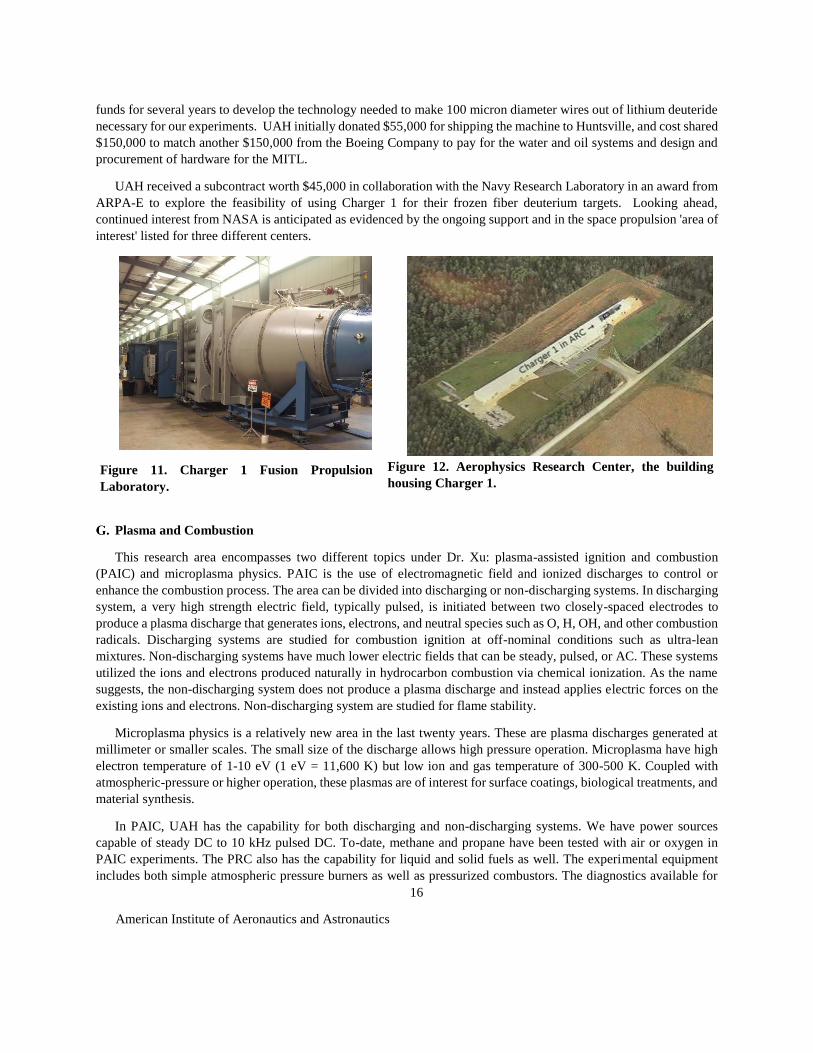
The fusion propulsion research underway at UAH utilizes Charger 1, a 550 kilojoule (kJ), 3 Terawatt (TW) pulsed
power machine as depicted in Fig. 11. Charger 1 is located on the Redstone Arsenal at the Aerophysics Research
Center (ARC) shown in Fig. 12. Charger 1 was developed by L-3 Communications Pulsed Sciences division on a
Defense Threat Reduction Agency (DTRA) contract, and it was originally used for nuclear weapons effects testing.
UAH acquired the machine in May of 2012, with assistance from the Boeing Company.
Since then, UAH has worked regularly with the NASA Marshall Space Flight Center, Boeing, and the Y-12
National Security Complex to make Charger 1 operational to conduct advanced propulsion experiments. The Defense
Threat Reduction Agency (DTRA) spent $850,000 to safely dismantle Charger 1 to have it shipped to Huntsville from
its original location in San Leandro, CA. UAH won a $300,000 award from the state of Alabama through its
innovation fund to help towards refurbishing and assembling the main sections of the machine. This included
rebuilding and replacement over 200 custom water-based resistors. NASA MSFC has provided labor, materials and
supplies, vacuum chambers over the last four years and most recently was critical to achieving operation of the control
system, which became operational in December 2016. Boeing paid for the 15,000 gallons of transformer oil needed
for the capacitor bank and the water deionization system needed for the transmission line. Y-12 has invested internal
American Institute of Aeronautics and Astronautics
16
funds for several years to develop the technology needed to make 100 micron diameter wires out of lithium deuteride
necessary for our experiments. UAH initially donated $55,000 for shipping the machine to Huntsville, and cost shared
$150,000 to match another $150,000 from the Boeing Company to pay for the water and oil systems and design and
procurement of hardware for the MITL.
UAH received a subcontract worth $45,000 in collaboration with the Navy Research Laboratory in an award from
ARPA-E to explore the feasibility of using Charger 1 for their frozen fiber deuterium targets. Looking ahead,
continued interest from NASA is anticipated as evidenced by the ongoing support and in the space propulsion 'area of
interest' listed for three different centers.
Figure 11. Charger 1 Fusion Propulsion
Laboratory.
Figure 12. Aerophysics Research Center, the building
housing Charger 1.
Plasma and Combustion
This research area encompasses two different topics under Dr. Xu: plasma-assisted ignition and combustion
(PAIC) and microplasma physics. PAIC is the use of electromagnetic field and ionized discharges to control or
enhance the combustion process. The area can be divided into discharging or non-discharging systems. In discharging
system, a very high strength electric field, typically pulsed, is initiated between two closely-spaced electrodes to
produce a plasma discharge that generates ions, electrons, and neutral species such as O, H, OH, and other combustion
radicals. Discharging systems are studied for combustion ignition at off-nominal conditions such as ultra-lean
mixtures. Non-discharging systems have much lower electric fields that can be steady, pulsed, or AC. These systems
utilized the ions and electrons produced naturally in hydrocarbon combustion via chemical ionization. As the name
suggests, the non-discharging system does not produce a plasma discharge and instead applies electric forces on the
existing ions and electrons. Non-discharging system are studied for flame stability.
Microplasma physics is a relatively new area in the last twenty years. These are plasma discharges generated at
millimeter or smaller scales. The small size of the discharge allows high pressure operation. Microplasma have high
electron temperature of 1-10 eV (1 eV = 11,600 K) but low ion and gas temperature of 300-500 K. Coupled with
atmospheric-pressure or higher operation, these plasmas are of interest for surface coatings, biological treatments, and
material synthesis.
In PAIC, UAH has the capability for both discharging and non-discharging systems. We have power sources
capable of steady DC to 10 kHz pulsed DC. To-date, methane and propane have been tested with air or oxygen in
PAIC experiments. The PRC also has the capability for liquid and solid fuels as well. The experimental equipment
includes both simple atmospheric pressure burners as well as pressurized combustors. The diagnostics available for

American Institute of Aeronautics and Astronautics
17
this research at the PRC include Langmuir probes, high-speed imaging, chemiluminescence, emissions spectroscopy,
and laser induced fluorescence. In microplasmas, the same set of power sources and diagnostics can be applied to
study atmospheric pressure discharges. We have two small vacuum chambers suitable for variable pressure testing
with different gases down to 10-6 Torr as well as a large vacuum chamber for environmental testing.
Recent papers published in PAIC have demonstrated, for the first time, the suppression of thermoacoustic
instabilities in a Rijke tube using solely electric fields.69,70 Publications in microplasma have focused on diagnostic
development to study these small scale plasmas using physical and optical technique.71,72 A new project in
microplasma for diode pumped rare gas lasers is beginning at the PRC supported by the Army Space Missile Defense
Command.
Computational Modeling
Accurate modeling of radiative heat transfer is critical to atmospheric science applications, as well as propulsion
systems, including combustion chambers and rocket-engine plumes. The objectives of our study are to: (1) predict
radiative heat transfer using the wide band, narrow band, and global property models, and (2) compare the results
obtained with those from line-by-line (LBL) simulations performed using the latest HITRAN and HITEMP databases.
The five radiative property models considered in the current study are the Edwards Wide Band Model73 (EWBM),
Spectrally-Resolved Exponential Wide Band Model (SR-EWBM), Elsasser Narrow Band Model74 (Elsasser NBM),
Malkmus Narrow Band Model75 (Malkmus NBM), and the Spectral Line Weighted-Sum-of-Gray-Gases76 (SLW)
model. The problem considered consists of a non-gray, one-dimensional (1-D) enclosure containing H2O with uniform
temperature and species mass fraction. The radiative transfer equation (RTE) was solved using the Discrete Ordinates
Method (DOM). Figure 13 shows the results. First, the spectral absorption coefficients computed from these models
are compared with the LBL data obtained using the HITRAN and HITEMP databases. The effects of varying the
medium temperature and pressure, as well as the wall temperature, on the model predictions of radiative heat flux and
its divergence are studied through comparison with the corresponding data obtained using HITRAN and HITEMP.
For all of the medium temperatures and pressures considered, the SLW model predictions showed excellent agreement
and Malkmus NBM showed reasonable agreement with the HITEMP data. At lower temperatures (and at constant
pressure), the two wide band models and the Elsasser NBM showed reasonable agreement with HITEMP. At high
temperatures (and at constant pressure), the SR-EWBM and the Elsasser NBM showed poor agreement with HITEMP.
At low pressures (and at constant temperature), the two wide band models and the Elsasser NBM showed reasonable
agreement with HITEMP. However, at high pressures, the EWBM showed poor agreement with HITEMP. Finally,
we investigate DOM for a variety of cases, including isothermal, homogeneous, non-isothermal, inhomogeneous, and
mixture cases for HITRAN and HITEMP. Two-dimensional domains, as well as spatial inhomogeneities in
temperature and species concentrations, will also be considered in the future work.

American Institute of Aeronautics and Astronautics
18
Figure 13. Absorption coefficient of H2O at a pressure of 1.0 atm, temperature of 3000 K, and a mole fraction
of 1.0 are shown as a function of wavenumber. Line-by-line absorption coefficients obtained from the
HITEMP77 2010 and HITRAN78 2012 databases are compared with the absorption coefficients predicted
using the Malkmus NBM, Elsasser NBM, EWBM, and SR-EWBM.
Aerospace Materials and Structures
The Aerospace Materials and Structures group at the PRC specializes in materials relevant to a diverse set of
aerospace applications ranging from advanced alloys for structural application to novel materials for energy
conversion and storage. The group is comprised of UAH Mechanical & Aerospace Engineering faculty and research
staff from the UAH Research Institutes. Here, we highlight recent efforts in additive manufacturing led by Dr. Judy
Schneider, 3D X-ray imaging of energy materials and propellants led by Dr. George Nelson, and material functionality
under extreme environments led by Dr. Hazeli.
1. Use of Additive Manufacturing in Aerospace Materials and Structures
A major component of a liquid rocket engine (LRE) is the combustion chamber and nozzle. This contains the
hot combustion gases as they are injected into the chamber, pass through the throat, and are expanded into the nozzle
and skirt providing the thrust needed to propel the LRE upward.79 Depending on the propellants, the combustion
gases can exceed 3300º C, a very severe environment for material survivability. Thus, the design and fabrication of a
large LRE assembly relies on a tradeoff between overall weight and survivability. While the lightest weight solution
would be fabrication from monolithic materials that can withstand the combustion environment without various
1.E-10
1.E-09
1.E-08
1.E-07
1.E-06
1.E-05
1.E-04
1.E-03
1.E-02
1.E-01
1.E+00
1.E+01
1.E+02
0 2000 4000 6000 8000 10000
Ab
sorp
tio
n C
oef
fici
ent,
cm
-1
Wavenumber, cm-1
Absorption Coefficient vs WavenumberH2O; T=3000K; XH2O=1.0; P=1.0atm; L=0.5m
HITEMP
HITRAN
Malkmus NBM
Elsasser NBM
EWBM
SR-EWBM
American Institute of Aeronautics and Astronautics
19
cooling schemes, these are generally expensive or have limited availability. Carbon/carbon nozzle construction
provides the lightest weight option without cooling, but the materials are costly and facilities to construct large
composite structures are limited, if they exist at all. Metals, such as rhenium, could survive the combustion
environment without cooling, but their use is cost prohibitive.
To be able to fabricate the LRE assembly from less exotic metals and alloys, active internal coolant passages are
used in the chamber and in the nozzle region just downstream of the throat. Typically, the alloy selection is based on
the desired property of either strength (Ni based) or conductivity (Cu based). The incoming liquid propellants flow
through the coolant passages to remove heat from the chamber, thereby preheating them in a regenerative fashion.
Various fabrication options have been explored to produce the bi-metallic combustion chamber/nozzle components
with internal coolant passages. Past design approaches have explored the use of brazed tube bundles, channel wall
nozzles, slotted chamber/electroplated close-out jacket, and diffusion bonded platelet construction.80 Many of these
fabrication technologies were used in the construction of the Space Shuttle Main Engine (SSME) or RS-25.
While the RS-25 engine design flew for over 30 years, each LRE assembly was very costly with conservative
estimates of $48 million each.81 With the retirement of the Space Shuttle, the NASA and other companies are
investigating various advanced design concepts and fabrication techniques for LRE combustion chamber/nozzles to
be used on the Space Launch System (SLS) to reduce fabrication time and costs. The first stage of the SLS uses the
RS-25 LREs which is driving the need to reduce production costs. Advanced materials and manufacturing
technologies will be required to meet this challenge to reduce the weight and the fabrication time while producing a
low cost component with high structural integrity.
One of the emerging new technologies being pursued for the fabrication of LRE components is the use of additive
manufacturing (AM) processes which can result in a significant time savings and cost reduction. AM can be used to
build complex shapes in low volumes on one platform. Use of powder bed AM is a viable solution for performance
improvements and reduction of manufacturing time and cost of smaller complex, monolithic components such as
injectors, valve housings, and turbine components. Other techniques being applied to the fabrication of larger
combustion chambers/nozzles with multi-materials are referred to as free form or direct metal deposition and use
either blown powder and wire feed. These techniques print “outside the box” and are not limited in size or to the use
of monolithic feed stock. However most of the companies with the technology to produce AM parts lack the necessary
resources to evaluate the resulting material property which is controlled by the processing parameters of heat source
and deposition patterns. Control of the heat input and resulting microstructural development is very complex owing
to the non-equilibrium conditions of localized rapid heating, solidification, and re-melting. Various modeling efforts
are underway to understand and control the relationship between the process parameters and resulting temperature
gradients during a build.
The NASA-MSFC has invested heavily in powder bed technologies for the smaller monolithic components.
Complimentary research in Dr. Schneider’s laboratory at UAH is focused on evaluation of the various “out of the
box” AM methods. Under various grants including NASA and Navy STTRs, she is engaged with several of the
leading manufactures of free form or direct metal deposition printing.82-84 Figure 14 a) shows a typical bi-metallic
interface between copper and inconel alloys. This provides opportunities for her students to internship at various
companies to assist in production of test specimens for characterization and testing at UAH. In parallel, her research
group is also developing a continuum level, transient heat transfer model to capture the temperature distribution in an
AM build.85,86 Ultimately this will be integrated into a production setting to predict the temperature profile and guide
selection of processing parameters and deposition strategy. For integration of temperature prediction, resulting
microstructure and properties, a free form AM system, shown in Fig. 14 b), is being designed by a team of
undergraduates for their senior capstone design project at UAH.

American Institute of Aeronautics and Astronautics
20
a) b)
Figure 14. a) Typical interface achieved in free form AM between copper and Inconel alloys. b) Overview
of free from AM system being developed at UAH by undergraduate capstone design class.
2. 3D X-ray Imaging for Aerospace Materials and Structures
Next generation aerospace systems, from commercial aircraft to defense technology, present a growing need for
onboard power, often in reduced volumes. The advanced power technologies that will support this expansion,
particularly batteries and other electrochemical energy conversion and storage devices, require increased performance
and reliability to ensure mission success. Multiscale functional materials form the cornerstone of these advanced
technologies by storing energy, providing sites for chemical reactions and pathways for the transport of charge and
chemical reactants. Direct observation of the structure of next generation energy storage and conversion materials can
be achieved using non-destructive X-ray imaging methods.87,88
Using X-ray imaging methods PRC researchers led by Dr. George Nelson are actively exploring how the multiscale
geometry of these systems influences coupled flows of mass, charge, and energy. This multiscale, multiphysics
interaction has significant impacts on device performance and reliability. Most notably, this technique is being applied
to the imaging and analysis of battery electrodes through two projects supported by the National Science Foundation.
These projects focus on high capacity alloy anodes and spinel cathodes for lithium ion batteries. Alloy anodes offer
significantly higher Li storage capacity compared to graphite anodes, but lithium storage in these materials generates
substantial volume change (~180%) and accelerates performance degradation. Dr. Nelson’s team has recently
demonstrated the capability for spectroscopic imaging of these materials using a synchrotron X-ray source.89 The
observation of these changes during operation is being pursued. The effect of microstructural geometry on electrode
performance is also being analyzed through experimental studies90 and the use of nanotomography data as
computational domains in finite element simulations.91,92 The process of integrating microstructural data with
computational modeling is illustrated in Fig. 15.

American Institute of Aeronautics and Astronautics
21
Figure 15. The analysis process for X-ray nanotomography data (clockwise from upper left) starts with a
grayscale image of the electrode microstructure. Microstructural characterization provides particle
geometric data. Meshing and subsequent computational modeling permits correlation of microstructure to
performance.91
In addition to battery materials, Dr. Nelson’s team is applying X-ray imaging methods to the study of porous
hybrid rocket motors.93,94 Using the PRC X-ray imaging facility, these studies have revealed the internal pore structure
of end-burning porous hybrid grains, Fig. 16. As with the energy materials noted above, this complex pore structure
supports oxidant flow to the grain’s burn surface influencing the burn rate and thrust. The 3D image data permits non-
destructive measurement of porosity, pore sizes, internal surface area, and pore connectivity. These characteristics are
expected to provide insight into the influence porous grain microstructure on hybrid motor performance.

American Institute of Aeronautics and Astronautics
22
a) b)
Figure 16. a) The X-ray imaging system at the UAH Propulsion Research Center supports real time
radiography of chemically active samples and 3D tomography of inactive samples. b) A tomographic cross-
section of a porous hybrid rocket motor taken with this system reveals anisotropic porosity within the
propellant grain.93,94
3. Microstructure Quantification under Extreme Environments
The main objective of Dr. Hazeli’s group is to develop fundamental knowledge required to enhance material
functionality under extreme environments such as high strain rate deformation, elevated temperatures, impact, high
radiation fluxes, or a multitude of the above factors for defense, aerospace and propulsion applications. The goal is to
investigate the constitutive response and roles of evolving intrinsic field variables to provide kinematic, kinetic, and
dynamic descriptions of failure mechanisms in critical structural materials. Dr. Hazeli’s current concern is on
understanding instability and failure of lattice structures at different strain rates. Lattice structures combine mechanical
properties of metals with various geometrical topologies, creating considerable potentials for light-weight energy-
absorbent structures, thermal management, and supports for vehicle and spacecraft appendages.
His lab, shown in Fig. 17, has the capability of performing multi-scale materials characterization covering a wide
range of strain rates and temperatures. Specifically, they can conduct low and high cycle fatigue, dynamic compression
(up to 104s−1), and tension (up to 103s−1) experiments all in the range from ambient temperature to 1,000◦C. In addition,
they can study materials under hypervelocity impacts (up to 107s−1) and radiation dominated plasma at the Aerophysics
Research Center (ARC) in UAH.
(a.) (b.)

American Institute of Aeronautics and Astronautics
23
Figure 17. Performing high strain rate deformation test using split Hopkinson pressure bar (Kolsky bar).
High strain rate data are required for safety and structural integrity assessment of structural materials
subjected to impact and dynamic loading. Left to right: Andrew Minor (MS student), Madison Frederick
(BS student), Dr. Hazeli, and Joe Indeck (PhD student)
Propellants and Energetics
1. Electrolytic Combustion Investigations
This research activity is under the direction of Dr. Robert Frederick and Dr. James Baird with support from Dr.
David Lineberry and performed by Ph.D. students Andrew Hiatt and Joshua Lang. The work is sponsored by the
Missile Defense Agency. The fundamental research involves experiments and analysis of electric solid propellants.
These propellants ignite and extinguish under certain conditions upon the application and removal of electrical power
applied to electrodes in contact with the propellant surface as illustrated in Fig. 18. For the propellant and conditions
investigated, the experimental program revealed that combustion occurred at the anode or the cathode depending on
the electrode area ratio configuration.95 Furthermore, a fundamental electrolytic theory describing the possible
chemistry and physics behind the observed phenomena at atmospheric conditions has been developed and presented.96
The current theory accounts for the effects of polarity and electrode area ratio. Additional experiments and theoretical
work continue.

American Institute of Aeronautics and Astronautics
24
2. Injector Spray Investigations
This research activity was under the direction of Dr. Robert Frederick with support from Dr. David Lineberry. The
work has been sponsored by Alabama Space Grant Fellowships, NASA MSFC, and internal UAH funding. Doctoral
students Chad Eberhart3and Brian Sweeney6 received Ph.D.’s last year as a result of their dissertations and publications
on this work. The overall objective of the work is to understand the fluid dynamics of different rocket injector elements
and the resulting spray behaviors though experimental investigations of water and air flows by controlling the injector
dimensional and flow configurations.
The impinging injector research examined the effect of jet breakup
length on the spray characteristics of like doublet injectors97 Cold-flow
experiments using water at atmospheric pressure systematically
determined the effect of the jet breakup length to impingement distance
ratio on spray characteristics for like-doublet injectors as shown in Fig.
19. For ratios greater than one, a flat sheet was formed that subsequently
disintegrated into waves of ligaments and droplets. The breakup length of
the sheet increased with the Weber number up to a transition point where
it began to decrease with further increases of the Weber number. For
ratios equal to one, an unsteady flat sheet was formed due to the jets
intermittently disintegrating before reaching the impingement point. New
empirical sheet breakup length and transition correlations were developed
for these configurations. For ratios less than one, no sheet was formed. In
addition, measurements of the ligament wavelengths and centerline
droplet diameters were conducted for jet breakup length to impingement
distance ratios greater than or equal to one. The mean ligament
wavelengths were nearly constant for all operating conditions,
impingement angles, and ratios. However, larger impingement angles and
jet velocities corresponded with smaller mean droplet diameters and reduced spray polydispersity. Mean droplet
diameters were independent of the jet breakup length to impingement distance ratio.
Figure 18. Representative chemical composition of an electric solid propellant consisting primarily of polyvinyl
alcohol (PVA) and hydroxylammonium nitrate (HAN) and the electric circuit used for ignition.95
Figure 19. Spray Snapshots: 90 degree
impingement angle.97

American Institute of Aeronautics and Astronautics
25
Several experimental and analytical studies pertaining to different
aspects of swirl injector dynamics were published last year as well.98-
100 In the experimental work, the lower boundaries at which an
injector's spray switches from non-pulsatile behavior to self-pulsation
were experimentally characterized under water and air flow conditions
for a liquid-centered swirl coaxial element configured both with and
without inner post recess as shown in Fig. 20. Data-based modal
decomposition analyses were used to extract distinct near-field spray
dynamics from high-speed Schlieren imagery. Liquid stripping from
the contiguous spray cone was observed in a flow regime where
coaxial flows are known to experience fiber-type breakup due to
hydraulic and aerodynamic instabilities. These periodic, non-pulsatile
spray breakup patterns were detected as a precursor to self-pulsation.
The frequency of these non-pulsatile patterns ranged from ∼1–4 kHz
and compared well with the frequency of self-pulsation at its onset,
which directly supports conventional ideas related to the mechanism
of self-pulsation. The transition of spray dynamics from non-pulsatile
to self-sustained oscillations showed a destabilizing/stabilizing effect
as gas velocity increases, establishes a temporally unstable spray oscillation at onset, and suggests that self-pulsation
may be excited when stripping behavior engages one or more fluid oscillators of the injector element. Different fluid
oscillators within the injector were assessed analytically and their contribution to the self-pulsation phenomenon were
studied.100
3. Axial-Injection, End-Burning Hybrid Motor Investigations
This research activity was under the direction
of Dr. Robert Frederick with assistance from Dr.
David Lineberry. Matthew Hitt conducted the
study and received a Ph.D.4 for a dissertation on
this topic in 2016. The work was supported by a
SMART Fellowship and internal UAH funding.
The research evaluated the burning rate
characteristics and process of axial-injection,
end-burning hybrid rocket motors in order to
increase the fuel regression rates.101,102, In this
configuration, the oxidizer flows through a porous grain or small ports to the burning surface where combustion
occurs. This design is in contrast to conventional hybrids where combustion occurs in ports cast into the grain. The
configuration of an axial-injection, end-burning hybrid rocket motor is shown in Fig. 21.103 Testing was conducted
using polyethylene as the porous fuel and gaseous oxygen as the oxidizer. Nominal test articles were tested using 200,
100, 50, and 15 μm pore sizes. Propellants tested included polyethylene for the fuel and gaseous oxygen and nitrous
oxide for the oxidizer. Experimental results confirmed that the regression rate of the porous axial-injection, end-
burning hybrid was a function of the chamber pressure, as opposed to the oxidizer mass flux typical in conventional
hybrids. Pressures tested ranged from atmospheric to 1194 kPa, yielding regression rates ranging from approximately
0.20 mm/s at atmospheric pressure to 8.89 mm/s at 1194 kPa. To describe the motor physics, an analytical model was
developed based on a standard ablative model modified to include oxidizer flow through the grain. The heat transfer
from the flame was primarily modeled using an empirically determined flame coefficient that included all heat transfer
mechanisms in one term. In addition, an exploratory flame model based on the Granular Diffusion Flame model used
for solid rocket motors was also adapted for comparison with the empirical flame coefficient. This model showed
Figure 20. Lower boundaries of self-
pulsation for each test recess ratio
configuration of swirl-coaxial injector.99
Figure 21. Axial-injection, end-burning hybrid.103

American Institute of Aeronautics and Astronautics
26
agreement with the experimental results, indicating that it has potential for giving insight into the flame structure in
this motor configuration.
Propulsion Systems Technology Testbed
1. UAH Student Launch Initiative (SLI) Team
The UAH Charger Rocket Works competed in the NASA Student Launch Competition on April 8, 2017 in Bragg
Farm Alabama. The team designed, built, and flew a sounding rocket to 5,160 feet in the national launch competition.
The team consisted of 15 students from the UAH Mechanical & Aerospace Engineering department. The 6-in.
diameter rocket was 119 in. long, and was launched on an Aerotech L2200 solid rocket motor. The rocket airframe
had a secondary set of actively controlled fins located forward of the main to control the roll rate of the rocket.
Throughout the 9 month program, the team conducted 2 subscale and 5 full scale flights to verify the aerodynamics
of the rockets and the roll control system design. In the competition, the UAH team placed 4 th nationally. The team
designed and built the rocket as part of a senior design class in the Mechanical & Aerospace Engineering Department
at UAH under the direction of Dr. David Lineberry and Mr. Jason Winningham.
Figure 22. UAH 2016-2017 SLI team and team mentor Jason Winningham
pose with their rocket at the Student Launch National Competition.
2. Propulsion Testing
During the 2016-2017 academic year, the PRC conducted tests of solid rocket motors, hybrid engines, and liquid
rocket engines for a variety of customers including Gloyer-Taylor Laboratories, NASA MSFC, Vector Space Systems,
C3 Propulsion, and the Missile Defense Agency. Test campaigns included hot fire testing with liquid oxygen, nitrous
oxide, RP-1, and methane propellants, AP composite solid rocket motors, and HTPB based hybrid motor grains.
Testing included thrust levels up to 500 lbf and chamber pressures up to 800 psi.

American Institute of Aeronautics and Astronautics
27
IV. People Make the Difference
During the past year, we continued to intentionally build relationships with each other and our community. The
PRC hosted monthly student mentoring cookout lunches at the lab that included guest speakers and tours of the
facilities for guests. We hosed our 25th anniversary celebration in October of 2016, which featured a banquet, a
propulsion symposium with joint talks from alumni and current students, and a cookout at the lab. Over 200 people
participated in these celebratory events. Our PRC Student Association (PRCSA) continued to support outreach events
such as Girls Science and Engineering Day, the regional Science Olympiad, and NASA in the Park, a Huntsville
tradition.
Each year we hold two celebrations honoring our upcoming graduates and all the departments around campus that
provide the support that makes our efforts successful. Figure 23 shows the PRC team at our December 2016 gathering.
Figure 23. Propulsion Research Center faculty, staff, students, colleagues, and friends at the fall 2016
Recognition of Graduates Reception.
“Keep relationships more important than tasks or problems” –Dr. Robert A. Frederick, Jr.
V. Strategies for the Future
Current growth areas that we are pursuing include upgrading our Propulsion Test Capability for MDA Systems,
adding run time capacity to our Supersonic Wind Tunnel, growing propulsion systems engineering research (starting

American Institute of Aeronautics and Astronautics
28
with nuclear thermal propulsion systems), and the growth of additive manufacturing research for propulsion
applications. The PRC will be completing a strategic planning exercise led by Dr. Dale Thomas this year.
Acknowledgments
The authors acknowledge the inputs and contributions of the faculty, staff, students, and graduates of the
Propulsion Research Center for providing valuable inputs and suggestions for this paper. Molly Kitts, PRC Office
Assistant, was the key contributor to compiling and editing this paper.
The support of the UAH Vice President for Research Office, and the UAH College of Engineering are gratefully
acknowledged. Thanks also go to our recent sponsors: The Missile Defense Agency, The State of Alabama
Department of Commerce, NASA MSFC, Hyper V Technologies, Boeing, Inc., Exquadrum, Inc., Varian Medical
Systems, C3 Propulsion, Combustion Research and Flow Tech. Inc., Aerojet Rocketdyne, Analysis and Applications
Inc., Department of the Navy – NRL, Gloyer-Taylor Laboratories, IHI Corporation, Jacobs, the State of Alabama,
NASA Alabama Space Grant, Manufacturing Technology Solutions, and Solar Turbines. Grateful acknowledgement
to all those potential customers who partnered with us to write proposals last year.
References
1 Hawk, C.W. and Frederick, R.A., “University Propulsion Programs at the University of Alabama in Huntsville,”
AIAA Paper 2004-3323, July 2004.
2 Frederick, R. A., “UAH Propulsion Research Center - 25th Anniversary Highlights,” AIAA Paper 2016-4722, 2016,
http://dx.doi.org/10.2514/6.2016-4722.
3 Eberhart, C., "An Investigation of Liquid Rocket Swirl Coaxial Injection under Self-excited High Frequency
Oscillations,” Ph.D. Dissertation, Mechanical & Aerospace Dept., the Univ. of Alabama in Huntsville, Advisor: Dr.
Robert Frederick, Jr., 2016.
4 Hitt, M., “Regression Rate Study of Porous Axial-Injection, End Burning Hybrid Fuel Grains,” Ph.D. Dissertation,
Mechanical & Aerospace Dept., The Univ. of Alabama in Huntsville, Advisor: Dr. Robert Frederick, Jr., 2016.
5 Dahriwal, R., "Stochastic Theory and Direct Numerical Simulations of the Relative Motion of High-Stokes-
Number Particles in Isotropic Turbulence," Ph.D. Dissertation, Mechanical & Aerospace Dept., the Univ. of
Alabama in Huntsville, Advisor: Dr. Sarma Rani, 2016.

American Institute of Aeronautics and Astronautics
29
6 Sweeney, B., “Like-Double Injectors: The Effects of Varying the Impingement Distance and an Analysis of the
Primary Atomization Zone,” Ph.D. Dissertation, Mechanical & Aerospace Dept., The University of Alabama in
Huntsville, Advisor: Dr. Robert Frederick, Jr., 2016.
7 Jeffires, S., and Hirshorn, S., “Study on NASA’s Technology Readiness Assessment (TRA) Process,” presented at
the NASA Program and Project Management Board, July 2014.
8 Szajnfarber, Z. and Weigel, A. L., “A Process Model of Technology Innovation in Governmental Agencies:
Insights from NASA’s Science Directorate,” Acta Astronaut., vol. 84, pp. 56–68, Mar. 2013.
9 “NASA Technology Roadmaps TA 11: Modeling, Simulation, Information Technology, and Processing,” National
Aeronautics and Space Administration, July 2015.
10 Aueron, A., and Thomas, L. D., “Nuclear Thermal Propulsion System Modeling using Model Based Systems
Engineering,” Joint Army Navy NASA Airforce (JANNAF) In-Space Chemical Propulsion Technical Interchange
Meeting, April 2017.
11 Grilli, M., Schmid, P. J., Hickel, S., and Adams, N. A., “Analysis of Unsteady Behavior in Shockwave Turbulent
Boundary Level Interaction,” Journal of Fluid Mechanics, Vol. 700, pp. 16–28, 2012.
12 Pirozzoli, S., Larsson, J., Nichols, J. W., Bernardini, M., Morgan, B. E., and Lele, S. K. “Analysis of Unsteady
Effects in Shock/Boundary Layer Interactions,” Proceedings of the Summer Program 2010, Center for Turbulence
Research, pp. 153–164, 2010.
13 Zhang, Q., O’Dowd, D. O., He, L., Wheeler, A. P. S., Ligrani, P. M., and Cheong, B. C. Y., “Overtip Shock Wave
Structure and Its Impact on Turbine Blade Tip Heat Transfer, ” ASME Transactions-Journal of Turbomachinery, Vol.
133, No. 4, pp. 041001-1 to 041001-8, 2011.
14 Zhang, Q., O’Dowd, D. O., He, L., Oldfield, M. L. G., and Ligrani, P. M., “Transonic Turbine Blade Tip
Aerothermal Performance with Different Tip Gaps—Part 1: Tip Heat Transfer,” ASME Transactions-Journal of
Turbomachinery, Vol. 133, No. 4, pp. 041027-1 to 041027-9, 2011b.

American Institute of Aeronautics and Astronautics
30
15 Abhari, R. S., Guenette, G. R., Epstein, A. H., and Giles, M. B. “Comparison of Time-Resolved Turbine Rotor
Blade Heat Transfer Measurements and Numerical Calculations,” ASME Transactions-Journal of Turbomachinery,
Vol. 114, No. 4, pp. 818-827, 1992.
16 Hayashi, M., Aso, S., and Tan, A. “Fluctuation of Heat Transfer in Shock Wave/Turbulent Boundary-Layer
Interaction,” AIAA Journal, Vol. 27, No. 4, pp. 399-404, 1989.
17 Lee, Y., Settles, G., and Horstman, C. “Heat Transfer Measurements and CFD Comparison of Swept Shock
Wave/Boundary-Layer Interactions,” AIAA 28th Joint Propulsion Conference and Exhibit, Paper No. AIAA-92-3665,
Nashville, Tennessee, 1992.
18 Nix, A. C., Diller, T. E., Ng, W. F., and Schetz, J. A., “Experimental Evaluation of Heat Transfer Effects of Shock
Waves on Transonic Turbine Blades,” ASME International Mechanical Engineering Congress and Exhibition, ASME
Paper No. 97-WA/HT-1, Dallas, Texas, 1997.
19 Schülein, E., “Skin Friction and Heat Flux Measurements in Shock/Boundary Layer Interaction Flows,” AIAA
Journal, Vol. 44, No. 8, pp. 1732-1741, 2006.
20 Ligrani, P. M., Jiang, H., Lund, B., and Jin, J. S., “Deviations Due To Non-Newtonian Influences Within a Miniature
Viscous Disk Pump,” ASME Transactions-Journal of Fluids Engineering, Vol. 135, No. 3, Mar. 13, pp. 031205-1 to
031205-12.
21 Blanchard, D. B., Ligrani, P. M., and Gale, B. K., “Miniature Single-Disk Viscous Pump (Single-DVP),
Performance Characterization,” ASME Transactions-Journal of Fluids Engineering, Vol. 128, No. 3, May 2006, pp.
602-610.
22 Lund, B., Ligrani, P. M., and Fatemi, A., “Onset and Transition to Elastic Turbulence: Effects of Rheological
Property Variations for Polyacrylamide-Water Solutions,” 20th International Colloquium Tribology – Industrial and
Automotive Lubrication, Stuttgart/Ostfildern, Germany, Jan. 2016.
23 Lund, B., Ligrani, P. M., and Brown, M., “Development and Control of Elastic Turbulence within a Micro-Scale
Viscous Disk Pump,” Advances and Applications in Fluid Mechanics Journal, Vo. 19, No. 3, Aug. 2016, pp. 517-539.

American Institute of Aeronautics and Astronautics
31
24 Ligrani, P. M., Lund, B., and Fatemi, A., “Miniature Viscous Disk Pump: Performance Variations From Non-
Newtonian Elastic Turbulence,” ASME Transactions-Journal of Fluids Engineering, Vol. 139, No. 2, Feb. 2017, pp.
021104-01 to 021104-10.
25 McKinley, G. H., Pakdel, P., Oztekin, A., “Rheological and Geometric Scaling of Purely Elastic Flow Instabilities,”
Journal of Non-Newtonian Fluid Mechanics, Vol. 67, 1996, pp. 19-47.
26 James, D. F., “Boger Fluids,” Annual Review of Fluid Mechanics, Vol. 41, 2009, pp. 129-142.
27 Abed, W. M., Whalley, R. D., Dennis, D. J. C., and Poole, R. J, “Experimental Investigation of the Impact of Elastic
Turbulence on Heat Transfer in a Serpentine Channel,” Journal of Non-Newtonian Fluid Mechanics, Vol. 231, 2016,
pp. 68-78.
28 Whalley, R. D., Abed, W. M., Dennis, D. J. C., and Poole, R. J, “Enhancing Heat Transfer at the Micro-Scale Using
Elastic Turbulence,” Theoretical and Applied Mechanics Letters, Vol. 5, 2015, pp. 103-106.
29 Traore, B., Castelain, C., and Burghelea, T, “Efficient Heat Transfer in a Regime of Elastic Turbulence,” Journal
of Non-Newtonian Fluid Mechanics, Vol. 223, 2015, pp. 62-76.
30 De Gennes, P. G., “Coil‐Stretch Transition of Dilute Flexible Polymers under Ultrahigh Velocity Gradients,”
Journal of Chemical Physics, Vol. 60, No. 12, 1974, pp. 5030 to 5042.
31 Naschie, M. S. E., Athel, S. A., and Kapitaniak, T., “A Note on Elastic Turbulence and Diffusion,” Journal of Sound
and Vibration, Vol. 155, No. 3, 1992, pp. 515-522.
32 Burghelea, T., Segre, E., and Steinberg, V., “Elastic Turbulence in Von Karman Swirling Flow Between Two
Disks,” Physics of Fluids, Vol. 19, 2007, pp. 053104-1 to 053104-26.
33 Ligrani, P. M., Copeland, D., Ren, C., Su, M., and Suzuki, M., “Heat Transfer Enhancements From Elastic
Turbulence Using Sucrose-Based Polymer Solutions,” AIAA Journal of Thermophysics and Heat Transfer, to appear
2017.
34 Copeland, D., Ren, C., Su, M., and Ligrani, P. M., “Elastic Turbulence Influences and Convective Heat Transfer
within a Miniature Viscous Disk Pump,” International Journal of Heat and Mass Transfer, to appear 2017.

American Institute of Aeronautics and Astronautics
32
35 Rogers, N., Ren, Z., Buzzard, W. C., Sweeney, B., Tinker, N., Ligrani, P. M., Hollingsworth, K. D., Liberatore, F.,
Patel, R., Ho, S., and Moon, H. K., “Effects of Double Wall Cooling Configuration and Conditions on Performance
of Full-Coverage Effusion Cooling,” ASME Transactions-Journal of Turbomachinery, Vol. 139, No. 5, May 2017, pp.
051009-01 to 051009-13.
36 Ren, Z., Vanga, S. R., Rogers, N., Ligrani, P. M., Hollingsworth, K. D., Liberatore, F., Patel, R., Srinivasan, R., and
Ho, Y., “Internal and External Cooling of a Full Coverage Effusion Cooling Plate: Effects of Double Wall Cooling
Configuration and Conditions,” Paper Number GT2017-64921, ASME TURBO EXPO 2017: Turbomachinery
Technical Conference and Exposition, Charlotte, North Carolina, June 2017.
37 Ligrani, P. M., Ren, Z., Liberatore, R., Patel, R., Srinivasan, R., and Ho, Y., “Double Wall Cooling of a Full Coverage
Effusion Plate, Including Internal Impingement Array Cooling,” Paper Number IMECE2017-72066, IMECE 2017,
ASME International Mechanical Engineering Congress and Exposition, Tampa, Florida, Nov. 2017.
38 Buzzard, W. C., Ren, Z., Ligrani, P. M., Nakamata, C., and Ueguchi, S., “Influences of Target Surface Roughness
on Impingement Jet Array Heat Transfer, Part 1: Effects of Roughness Pattern, Roughness Height, and Reynolds
Number,” Paper Number GT2016-56354, ASME TURBO EXPO 2016: Turbomachinery Technical Conference and
Exposition, Seoul, South Korea, June 2016.
39 Buzzard, W. C., Ren, Z., Ligrani, P. M., Nakamata, C., and Ueguchi, S., “Influences of Target Surface Small-Scale
Rectangle Roughness on Impingement Jet Array Heat Transfer,” International Journal of Heat and Mass Transfer, to
appear 2017.
40 Buzzard, W. C., Ren, Z., Ligrani, P. M., Nakamata, C., and Ueguchi, S., “Influences of Target Surface Roughness
on Impingement Jet Array Heat Transfer, Part 2: Effects of Roughness Shape, and Reynolds Number,” Paper Number
GT2016-56355, ASME TURBO EXPO 2016: Turbomachinery Technical Conference and Exposition, Seoul, South
Korea, June 2016.

American Institute of Aeronautics and Astronautics
33
41 Ren, Z., Buzzard, W. C., Ligrani, P. M., Nakamata, C., and Ueguchi, S., “Impingement Jet Array Heat Transfer:
Target Surface Roughness Shape, Reynolds Number Effects,” AIAA Journal of Thermophysics and Heat Transfer, to
appear 2017.
42 Ren, Z., Buzzard, W. C., and Ligrani, P. M., “Influences of Target Surface Cylindrical Roughness on Impingement
Jet Array Heat Transfer: Effects of Roughness Height, Roughness Shape, and Reynolds Number,” Paper Number
IMECE2016-67655, IMECE 2016: ASME International Mechanical Engineering Congress and Exposition, Phoenix,
Arizona, Nov. 2016.
43 Ligrani, P. M., Ren, Z., and Buzzard, W. C., “Impingement Jet Array Heat Transfer with Small-Scale Cylinder
Target Surface Roughness Arrays,” International Journal of Heat and Mass Transfer, to appear 2017.
44 Yang, L., Ren, J., Jiang, H., and Ligrani, P. M., “Experimental and Numerical Investigation of Unsteady
Impingement Cooling Within a Blade Leading Edge Passage,” International Journal of Heat and Mass Transfer, Vol.
71, Apr. 2014, pp. 57-68.
45 Yang, L., Ligrani, P. M., Ren, J., and Jiang, H., “Unsteady Structure and Development of a Row of Impingement
Jets, Including Kelvin-Helmholtz Vortex Development,” ASME Transactions-Journal of Fluids Engineering, Vol. 137,
No. 5, May 2015, pp. 051201-1 to 051201-12.
46 Yang, L., Li, Y., Ligrani, P. M., Ren, J., and Jiang, H., “Unsteady Heat Transfer and Flow Structure of a Row of
Laminar Impingement Jets, Including Vortex Development,” International Journal of Heat and Mass Transfer, Vol.
88, Sept. 2015, pp. 149-164.
47 Li, W., Ren, J., Jiang, H., Luan, Y., and Ligrani, P. M, “Assessment of Six Turbulence Models For Modelling and
Predicting Narrow Passage Flows, Part 1: Impingement Jets,” Numerical Heat Transfer, Part A: Applications, Vol.
69, No. 2, Jan. 2016, pp. 109-127.
48 Li, W., Ren, J., Jiang, H., Luan, Y., and Ligrani, P. M, “Assessment of Six Turbulence Models For Modelling and
Predicting Narrow Passage Flows, Part 2: Pin Fin Arrays,” Numerical Heat Transfer, Part A: Applications, Vol. 69,
No. 5, Mar. 2016, pp. 445-463.

American Institute of Aeronautics and Astronautics
34
49 Li, W., Li, X., Yang, L., Ren, R., Jiang, H., and Ligrani, P. M., “Effect of Reynolds Number, Hole Patterns, and Hole
Inclination on Cooling Performance of an Impinging Jet Array - Part 1: Convective Heat Transfer Results and
Optimization,” ASME Transactions-Journal of Turbomachinery, Vol. 139, No. 4, Apr. 2017, pp. 041002-01 to
041002-11.
50 Winkler, S., Kerber, E., Hitz, T., Weigand, B., and Ligrani, P. M., “Numerical Second Law Analysis around a
Turbine Guide Vane Using a Two-Equation Turbulence Model and Comparison With Experiments,” International
Journal of Thermal Sciences, to appear 2017.
51 Ligrani, P. M., and Jin, J. S., “Second Law Analysis of Aerodynamic Losses: Results for a Cambered Vane With
and Without Film Cooling,” ASME Transactions-Journal of Turbomachinery, Vol. 135, No. 4, July 2013, pp. 041013-
1 to 041013-14.
52 Chung, Y. S., Lee, D. H., and Ligrani, P. M., “Jet Impingement Cooling of Chips Equipped With Cylindrical
Pedestal Profile Fins,” ASME Transactions-Journal of Electronic Packaging, Vol. 127, No. 2, June 2005, pp. 106-
112.
53Lee, D. H., Chung, Y. S., and Ligrani, P. M., “Jet Impingement Cooling of Chips Equipped With Multiple Cylindrical
Pedestal Fins,” ASME Transactions-Journal of Electronic Packaging, Vol. 129, No. 3, Sept. 2007, pp. 221-228.
54 Lee, D. H., Bae, J. R., Parks, H. J., Lee, J. S., and Ligrani, P. M., “Confined, Milliscale Unsteady Laminar Impinging
Slot Jets and Surface Nusselt Numbers,” International Journal of Heat and Mass Transfer, Vol. 54, Nos. 11-12, May
2011, pp. 2408-2418.
55 Lee, D. H., Park, H. J., and Ligrani, P. M., “Milliscale Confined Impinging Slot Jets: Laminar Heat Transfer
Characteristics for an Isothermal Flat Plate,” International Journal of Heat and Mass Transfer, Vol. 55, Nos. 9-10,
Apr. 2012, pp. 2249-2260.
56 Lee, D. H., Bae, R. J., Ryu, M., and Ligrani, P. M., “Confined, Milliscale Unsteady Laminar Impinging Slot Jets:
Effects of Slot Width on Surface Stagnation Point Nusselt Numbers,” ASME Transactions – Journal of Electronic
Packaging, Vol. 134, No. 4, Dec. 2012, pp. 041004-1 to 041004-11.

American Institute of Aeronautics and Astronautics
35
57 Kim, S. J., Kim, Y. H., Park, H. J., Lee, D. H., and Ligrani, P. M., “Heat Transfer Measurements From Concave
and Convex Surfaces With a Fully Developed Confined Impinging Slot Jet,” The 15th International Heat Transfer
Conference, IHTC2014, Kyoto, Japan, Aug. 2014.
58 Lee, D. H., Park, H. J., and Ligrani, P. M., “Visualization and Structure of Confined, Milliscale, Unsteady Impinging
Slot Jets and Associated Vortices,” Experiments in Fluids, Vol. 54:1420, 2013, pp. 1-15.
59 Nivedita, N., Ligrani, P. M., and Papautsky, I., “Spiral Inertial Microfluidic Devices For Continuous Blood Cell
Separation,” MOEMS-MEMS Conference on Micro- and Nano-Fabricated Electromechanical and Optical
Components, Paper Number 8251-26, SPIE – International Society for Optics and Photonics, San Francico, Jan. 2012.
60 Jennerjohn, M., Nivedita, N., Carlson, L., Ligrani, P. M., Papautsky, I., Eslick, J., Sprague, R., and Bowles, E.,
“Microfluidic Inertial, Continuous SPLITT, and Field-Flow Fractionation Developments for Separation of Whole
Blood Components,” 16th International Symposium on Field- and Flow-Based Separations, FFF2013-PAU, IPREM
and Faculty of Sciences Pau, University de Pau et des Pays de l’Adour, France, June-July 2013.
61 Ligrani, P. M., and Niver, R. D., “Flow Visualization of Dean Vortices in a Curved Channel with 40 to 1 Aspect
Ratio,” Physics of Fluids, Vol. 31, No. 12, Dec. 1988, pp. 3605-3617.
62 Ligrani, P. M., and Hedlund, C. R., “Experimental Surface Heat Transfer and Flow Structure in a Curved Channel
with Laminar, Transitional, and Turbulent Flows,” ASME Transactions-Journal of Turbomachinery, Vol. 126, No. 3,
July 2004, pp. 414-423.
63 Nivedita, N., Ligrani, P. M., and Papautsky, I., “Dean Flow Dynamics in Low-Aspect Ratio Spiral Microchannels,”
Scientific Reports, to appear, 2017.
64 Nivedita, N., Ligrani, P. M., and Papautsky, I., “Evolution of Secondary Dean Vortices in Spiral Microchannels for
Cell Separations,” Miniaturized Systems for Chemistry and Life Sciences MicroTAS 2013, University of Freiburg,
Freiburg, Germany, October 2013.
65 Adams, R. B., Cassibry, J. T., and Schillo, K., “Developing the Pulsed Fission-Fusion (PuFF) Engine,” 50th
AIAA/ASME/SAE/ASEE Joint Propulsion Conference. American Institute of Aeronautics and Astronautics,
http://arc.aiaa.org/doi/abs/10.2514/6.2014-3520, 2015.

American Institute of Aeronautics and Astronautics
36
66 Cassibry, J., Cortez, R., Stanic, M., Watts, A., Seidler, W., Adams, R., Statham, G., and Fabisinski, L., “Case and
Development Path for Fusion Propulsion,” Journal of Spacecraft and Rockets, Vol. 52, No. 2, doi:10.2514/1.A32782,
2015, pp. 595–612.
67 Ryutov, D. D., M. S. Derzon, and Matzen, M. K., “The Physics of Fast Z Pinches,” Reviews of Modern Physics,
Vol. 72, No. 167, doi:10.1103/RevModPhys, 2000.
68 Haines, M. G., “A Review of the Dense Z-Pinch,” Plasma Physics and Controlled Fusion, Vol. 53, No. 9, 093001,
doi:10.1088/0741-3335/53/9/093001, 2011.
69 Bradley, H., and Xu, K. G., “Electric Field Damping of Rijke Tube Combustion Instabilities,” AIAA Journal of
Propulsion and Power, accepted, 2017.
70 Salvador, P. R., and Xu, K. G., “Electric Field Modified Bunsen Flame with Variable Anode Placement,” J.
Thermophys. Heat Transf., accepted, 2017.
71 Doyle, S. J., and Xu, K. G., “Use of Thermocouples and Argon Line Broadening for Gas Temperature Measurement
in a Radio Frequency Atmospheric Microplasma Jet,” Rev. Sci. Instrum., Vol. 88, No. 2, 2017.
72 Xu, K. G., and Doyle, S. J., “Measurement of Atmospheric Pressure Microplasma Jet with Langmuir Probes
Measurement of Atmospheric Pressure Microplasma Jet with Langmuir Probes,” J. Vac. Sci. Technol, Vol. 34, No. 5,
2016
73 Edwards, D.K., and Menard, W.A., “Comparison of Models for Correlation of Total Band Absorption,” Applied
Optics, Vol. 3, 1964, pp. 621-625.
74 Elsasser, W.M., Heat Transfer by Infrared Radiation in the Atmosphere, Harvard UP, Cambridge, Massachusetts,
1943.
75 Malkmus, W., “Random Lorentz Band Model with Exponential-Tailed S-1 Line-Intensity Distribution Function,”
Journal of the Optical Society of America, Vol. 57, No. 3, 1957, pp. 323-329.
76 Denison, M.K., and Webb, B.W., “A Spectral Line-Based Weighted-Sum-of-Gray-Gases Model for Arbitrary RTE
Solvers,” ASME Journal of Heat Transfer, Vol. 115, 1993, pp. 1004-1012.

American Institute of Aeronautics and Astronautics
37
77 Rothman, L. S., et. al. “The HITRAN2012 molecular spectroscopic database,” Journal of Quantitative Spectroscopy
& Radiative Transfer, Vol. 130, 2013, pp. 4-50.
78 Rothman, L.S., et. al., “HITEMP, the high-temperature molecular spectroscopic database,” Journal of Quantitative
Spectroscopy & Radiative Transfer, Vol. 111, 2010, pp. 2139-2150.
79 Sutton, G.P., Rocket Propulsion Elements: an Introduction to the Engineering of Rockets, 5th ed. pub., John Wiley
& Sons, 1986.
80 Gradl, P., Brandsmeier, W., Alberts, D., Walker, B., and Schneider, J., “Manufacturing Process Developments for
Large Scale Regeneratively-cooled Channel Wall Rocket Nozzles,” JANNAF Programmatic and Industrial Base
(PIB) / 11th Modeling and Simulation (MSS) / 9th Liquid Propulsion (LPS) / 8th Spacecraft Propulsion Joint
Subcommittee Meeting, Phoenix, AZ, Dec. 2016.
81 Associated Press: National Edition, "Deep Discount on Space Shuttles," January 2010, pg. A20.
82 Cordner, S., Prater, T., and Schneider, J.A., “Density Based Screening of Additively Manufactured Parts,” JANNAF
TIM, Huntsville, AL, Aug. 2016.
83 Hill, T.C., Schneider, J.A., and Sporie, S., “Blown Powder Laser Deposition Study,” JANNAF TIM, Huntsville, AL,
Aug. 2016.
84 Schneider, J.A., Hyatt, G., and Babai, M., “Blown Powder Laser Deposition Additive/Subtractive Processing,”
AMMO DOD presentation, Aug. 2016.
85 Stockman, T., and Schneider, J. A., “Full Build Thermal Modeling of the Additive Manufacturing Process,” Young
Professional AIAA Conference, Huntsville, AL, Oct. 2016.
86 Stockman, T., Schneider, J.A., and Walker, B., “Managing Thermal History in Free Form Additive Manufacturing,”
JANNAF TIM, Huntsville, AL, Aug. 2016.
87 Nelson, G. J., van Zandt, Z. K., and Jibhakate, P. D., “Direct X-ray Imaging as a Tool for Understanding
Multiphysics Phenomena in Energy Storage,” ASME Journal of Electrochemical Energy Conversion and Storage,
Vol. 13, No. 3, 2016, Article 030802.

American Institute of Aeronautics and Astronautics
38
88 Cocco, A. P., Nelson, G. J., Harris, W. M., Nakajo, A., Lombardo, J. J., Myles, T. D., Kiss, A. M., and Chiu, W. K.
S., “Three Dimensional Microstructural Imaging Methods for Energy Materials,” Physical Chemistry Chemical
Physics, Vol. 15, No. 39, 2013, pp. 16377-16407.
89 L. J. Ausderau, H. J. Gonzalez, J. R. Buckley, V. De Andrade, Y. Liu and G. J. Nelson, “Elemental and Chemical
Mapping of High Capacity Intermetallic Li-ion Anodes with Transmission X-ray Microscopy,” JOM, 2017, in press.
90 Jibhakate, P. D., and Nelson, G. J., “Fabrication and Characterization of Nanostructured Cathodes for Li-Ion
Batteries,” Proceedings of IMECE2016: 2016 ASME International Mechanical Engineering Congress and Exposition,
Phoenix, Arizona, Nov. 2016.
91 Nelson, G. J., Ausderau, L. J., Shin, S. Y., Buckley, J. R., Mistry, A., Mukherjee, P. P., and De Andrade, V.,
“Transport-Geometry Interactions in Li-ion Cathode Materials Imaged Using X-ray Nanotomography,” Journal of the
Electrochemical Society, 2017, Vol. 164, No. 7, A1412-A1424.
92 Nelson, G. J., “A Numerical Investigation of Active Surface Accessibility in Li-ion Battery Cathodes,” Proceedings
of IMECE2016: 2016 ASME International Mechanical Engineering Congress and Exposition, Phoenix, Arizona, Nov.
2016.
93 Buckley, J. R., Denny, M. D., and Nelson, G. J., “Computed Tomography Characterization of a Porous Hybrid
Motor Grain,” 51st AIAA/SAE/ASEE Joint Propulsion Conference, Orlando, Florida, July 2015.
94 Buckley, J. R. and Nelson, G. J., “Computed Tomography Characterization of a Porous Hybrid Motor Grain with
added Contrast Agent,” 52nd AIAA/SAE/ASEE Joint Propulsion Conference, Salt Lake City, Utah, July 2016.
95 Hiatt, A. T., and Frederick, R. A., “Laboratory Experimentation and Basic Research Investigating Electric Solid
Propellant Electrolytic Characteristics,” AIAA Paper 2016-4935, July 2016, http://dx.doi.org/10.2514/6.2016-4935.
96 Baird, J. K., Lang, J. R., Hiatt, A. T., and Frederick, R. A., “Electrolytic Combustion in the Polyvinyl Alcohol +
Hydroxylammonium Nitrate Solid Propellant,” AIAA Paper 2016-4908, July 2016, http://dx.doi.org/10.2514/6.2016-
4908.
American Institute of Aeronautics and Astronautics
39
97 Sweeney, B., and Frederick, R. A., "Jet Breakup Length to Impingement Distance Ratio for Like-Doublets," AIAA
Journal of Propulsion and Power, Vol. 32, No. 6, 2016, pp. 1516-1530.
98 Eberhart, C. J., and Frederick, R. A., "Fluid Oscillations of a Swirl Coaxial Injector under High-Frequency Self-
Pulsation,” AIAA Journal of Propulsion and Power, advance, https://doi.org/10.2514/1.B36177.
99 Eberhart, C. J., and Frederick, R. A., "Details on the Mechanism of High-Frequency Swirl Coaxial Self-Pulsation,”
AIAA Journal of Propulsion and Power, advance, https://doi.org/10.2514/1.B36216.
100 Eberhart, C. J., and Frederick, R. A., "Parametric Evaluation of Swirl Injector Dynamics in the High-Frequency
Range,” AIAA Journal of Propulsion and Power, advance, https://doi.org/10.2514/1.B36221.
101 Hitt, M. A. and Frederick, R. A., "Testing and Modeling of a Porous Axial-Injection, End-Burning Hybrid Motor,"
Journal of Propulsion and Power, Vol. 32, No. 4, 2016, pp. 834-843, http://dx.doi.org/10.2514/1.B35939.
102 Hitt, M. A., and Frederick, R. A., "Experimental Evaluation of a Nitrous-Oxide Axial-Injection, End-Burning
Hybrid Rocket". AIAA Journal of Propulsion and Power, advance, https://doi.org/10.2514/1.B36439.
103 Nagata, H., Okada, K., San’da, T., Kato, T., Akiba, R., Satori, S., and Kudo, I., "Combustion Characteristics of
Fibrous Fuels for Dry Towel Hybrid Motor," Journal of Space Technology and Science, Vol. 13, No. 1, 1997, pp. 11-
16.