Embed Size (px)
Citation preview

Proposed Semester-wise B. Tech Curriculum Structure for EE
*Minimum credits: 160 Maximum credits: 165
1. Students from 5th semester and onwards may opt for inter-departmental courses in
conformity with the work force requirements in the industries within the credit range. 2. Students may also opt for Massive Open Online Courses (MOOCs) for 20% of the total
credit range in conformity with the concept of digital education. 3. For Open Elective courses: Students may opt for any course offered by the University
from the preferable subjects enlisted in Table A. and recommended by the department, as per AICTE guidelines.
4. Students will undergo a summer training of 6 weeks after 6th semester during summer vacation and submit the report and the certificate of completion in the department in the beginning of 7th semester
Semester-I
Sl.
No.
Course
Type
Code
Course Name L T P CR CH
1. CH 103 Chemistry 3 0 1 4 5
2. MS 104 Mathematics-I 3 1 0 4 4
3. EE 103 Basic Electrical Engineering 3 0 0 3 3
4. EE 104 Basic Electrical Engineering lab 0 0 1 1 2
5. PH 103 Physics-I 2 0 1 3 4
6. EF 103 English 2 0 1 3 4
7. SE 100 Induction Program - - - - 8
Total 13 1 4 18 22
Semester-II
Sl.
No.
Course
Type
Code
Course Name L T P CR CH
1. PH 104 Physics-II 2 0 0 2 2
2. MS 105 Mathematics-II 3 1 0 4 4
3. CE 103 Engineering Graphics 1 0 2 3 5
4. ME 103 Workshop Practice 0 0 2 2 4
5. CO 103
Introductory Computing /
Programming for
Problem Solving
3 0 0 3 3
6. CO 104 Computing Lab 0 0 2 2 4
7. ME 102 Engineering Mechanics 3 1 0 4 4
Total 12 2 6 20 26
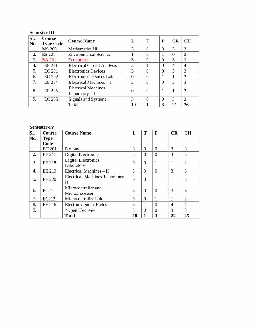
Semester-III
Sl.
No.
Course
Type Code Course Name L T P CR CH
1. MS 205 Mathematics III 3 0 0 3 3
2. ES 201 Environmental Science 1 0 1 0 3
3. BA 201 Economics 3 0 0 3 3
4. EE 211 Electrical Circuit Analysis 3 1 0 4 4
5. EC 201 Electronics Devices 3 0 0 3 3
6. EC 202 Electronics Devices Lab 0 0 1 1 2
7. EE 214 Electrical Machines – I 3 0 0 3 3
8. EE 215 Electrical Machines
Laboratory – I 0 0 1 1 2
9. EC 205 Signals and Systems 3 0 0 3 3
Total 19 1 3 21 26
Semester-IV
Sl.
No.
Course
Type
Code
Course Name L T P CR CH
1. BT 201 Biology 3 0 0 3 3
2. EE 217 Digital Electronics 3 0 0 3 3
3. EE 218 Digital Electronics
Laboratory 0 0 1 1 2
4. EE 219 Electrical Machines – II 3 0 0 3 3
5. EE 220 Electrical Machines Laboratory –
II 0 0 1 1 2
6. EC211 Microcontroller and
Microprocessor 3 0 0 3 3
7. EC212 Microcontroller Lab 0 0 1 1 2
8. EE 216 Electromagnetic Fields 3 1 0 4 4
9. *Open Elective-1 3 0 0 3 3
Total 18 1 3 22 25

Semester-V
Sl.
No.
Course
Type Code
Course Name L T P CR CH
1. EE 311
Power Systems – I (Apparatus
and Modelling) 3 0 0 3 3
2. EE 312
Power Systems
Laboratory – I 0 0 1 1 2
3. EE 313 Control Systems 3 0 0 3 3
4. EE 314 Control Systems Laboratory 0 0 1 1 2
5. EE 315 Power Electronics 3 0 0 3 3
6. EE 316 Power Electronics Laboratory 0 0 1 1 2
7. Program Elective – 1 3 0 0 3 3
8. *Open Elective – 2 3 0 0 3 3
9. LW 301 Indian Constitution 1 0 0 0 1
Total 16 0 3 18 22
For Program Elective – 1
EE 317 Electrical Machine Design
Semester-VI
Sl.
No.
Course Type
Code
Course Name L T P CR CH
1. IC 361 Accounting & Financial
Management 3 0 0 3 3
2. EE 318 Power Systems – II (Operation
and Control) 3 0 0 3 3
3. EE 319 Power Systems Laboratory - II 0 0 1 1 2
4. EE 320 Measurements and
Instrumentation Laboratory 2 0 2 4 6
5. EE 321 Electronics Design Laboratory 1 0 2 3 5
6. Program Elective – 2 3 0 1 4 5
7. Program Elective – 3 3 0 0 3 3
8. Open Elective – 3 3 0 0 3 3
9. EE 322 Summer Internship 0 0 0 0 0
Total 18 0 6 24 30
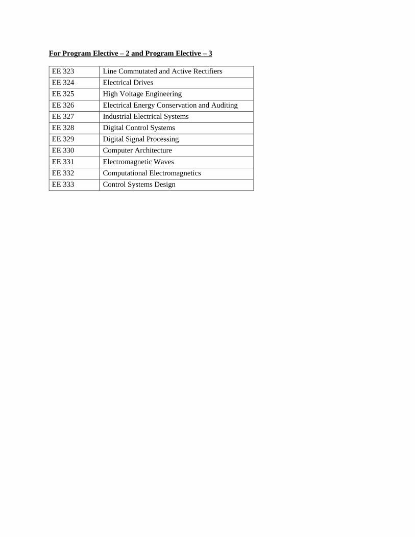
For Program Elective – 2 and Program Elective – 3
EE 323 Line Commutated and Active Rectifiers
EE 324 Electrical Drives
EE 325 High Voltage Engineering
EE 326 Electrical Energy Conservation and Auditing
EE 327 Industrial Electrical Systems
EE 328 Digital Control Systems
EE 329 Digital Signal Processing
EE 330 Computer Architecture
EE 331 Electromagnetic Waves
EE 332 Computational Electromagnetics
EE 333 Control Systems Design

Semester-VII Sl.
No.
Course
Type Code Course Name L T P CR CH
1. XX xxx HSS / Management Elective 3 0 0 3 3
2. Program Elective -4 3 0 0 3 3
3. Program Elective -5 3 0 0 3 3
4. Open Elective – 4 3 0 0 3 3
5. Open Elective – 5 3 0 0 3 3
6. EE 412 Project Stage-I 0 1 5 6 11
7. CT 430 Essence of Indian Traditional
Knowledge 1 0 0 0 1
Total 16 0 5 21 27
For Program Elective – 4 and Program Elective – 5
EE 413 Wind and Solar Energy Systems
EE 414 Electrical and Hybrid Vehicles
EE 415 Power System Protection
EE 416 HVDC Transmission Systems
EE 417 Power Quality and FACTS
EE 418 Power System Dynamics and Control
Semester-VIII
Sl.
No.
Course
Type
Code
Course Name L T P CR CH
1. Program Elective -6 3 0 0 3 3
2. Open Elective -6 3 0 0 3 3
3. EE 420 Project Stage-II 0 0 10 10 20
Total 6 0 10 16 26
For Program Elective – 6
EE 419 Advanced Electric Drives
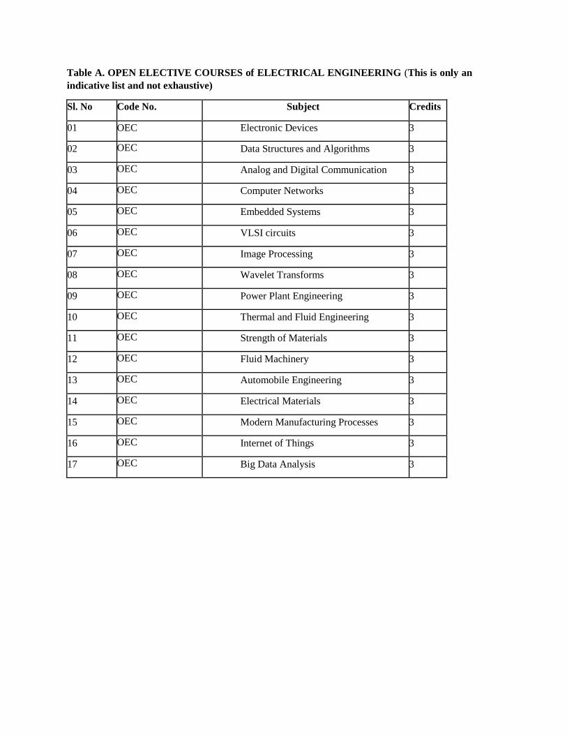
Table A. OPEN ELECTIVE COURSES of ELECTRICAL ENGINEERING (This is only an
indicative list and not exhaustive)
Sl. No Code No. Subject Credits
01 OEC Electronic Devices 3
02 OEC Data Structures and Algorithms 3
03 OEC Analog and Digital Communication 3
04 OEC Computer Networks 3
05 OEC Embedded Systems 3
06 OEC VLSI circuits 3
07 OEC Image Processing 3
08 OEC Wavelet Transforms 3
09 OEC Power Plant Engineering 3
10 OEC Thermal and Fluid Engineering 3
11 OEC Strength of Materials 3
12 OEC Fluid Machinery 3
13 OEC Automobile Engineering 3
14 OEC Electrical Materials 3
15 OEC Modern Manufacturing Processes 3
16 OEC Internet of Things 3
17 OEC Big Data Analysis 3
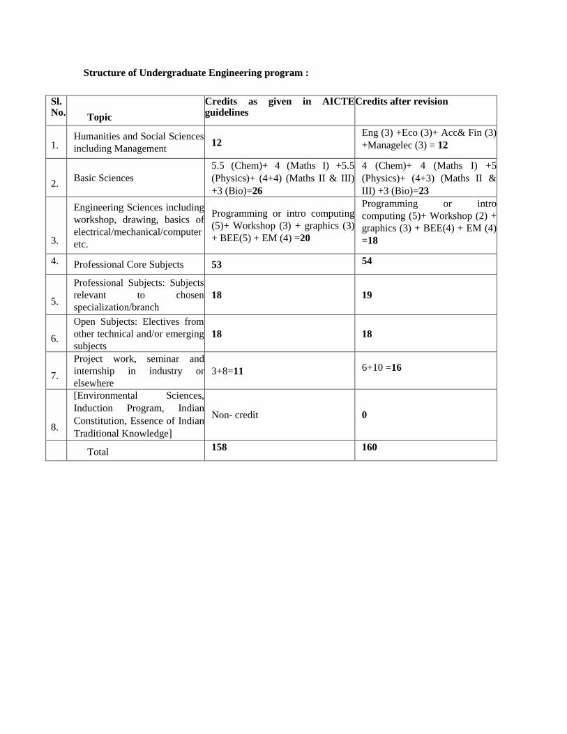
Structure of Undergraduate Engineering program :
Sl. No.
Topic
Credits as given in AICTE guidelines
Credits after revision
1. Humanities and Social Sciences
including Management 12
Eng (3) +Eco (3)+ Acc& Fin (3)
+Managelec (3) = 12
2. Basic Sciences
5.5 (Chem)+ 4 (Maths I) +5.5
(Physics)+ (4+4) (Maths II & III)
+3 (Bio)=26
4 (Chem)+ 4 (Maths I) +5
(Physics)+ (4+3) (Maths II &
III) +3 (Bio)=23
3.
Engineering Sciences including
workshop, drawing, basics of
electrical/mechanical/computer
etc.
Programming or intro computing
(5)+ Workshop (3) + graphics (3)
+ BEE(5) + EM (4) =20
Programming or intro
computing (5)+ Workshop (2) +
graphics (3) + BEE(4) + EM (4)
=18
4. Professional Core Subjects 53 54
5.
Professional Subjects: Subjects
relevant to chosen
specialization/branch
18 19
6.
Open Subjects: Electives from
other technical and/or emerging
subjects
18 18
7.
Project work, seminar and
internship in industry or
elsewhere
3+8=11 6+10 =16
8.
[Environmental Sciences,
Induction Program, Indian
Constitution, Essence of Indian
Traditional Knowledge]
Non- credit 0
Total
158 160

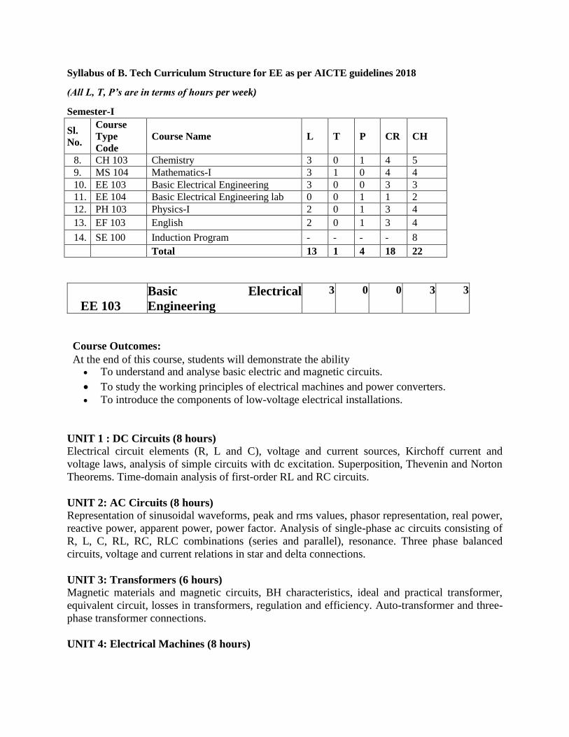
Syllabus of B. Tech Curriculum Structure for EE as per AICTE guidelines 2018
(All L, T, P’s are in terms of hours per week)
Semester-I
Sl.
No.
Course
Type
Code
Course Name L T P CR CH
8. CH 103 Chemistry 3 0 1 4 5
9. MS 104 Mathematics-I 3 1 0 4 4
10. EE 103 Basic Electrical Engineering 3 0 0 3 3
11. EE 104 Basic Electrical Engineering lab 0 0 1 1 2
12. PH 103 Physics-I 2 0 1 3 4
13. EF 103 English 2 0 1 3 4
14. SE 100 Induction Program - - - - 8
Total 13 1 4 18 22
EE 103
Basic Electrical
Engineering
3 0 0 3 3
Course Outcomes: At the end of this course, students will demonstrate the ability
To understand and analyse basic electric and magnetic circuits.
To study the working principles of electrical machines and power converters.
To introduce the components of low-voltage electrical installations.
UNIT 1 : DC Circuits (8 hours)
Electrical circuit elements (R, L and C), voltage and current sources, Kirchoff current and
voltage laws, analysis of simple circuits with dc excitation. Superposition, Thevenin and Norton
Theorems. Time-domain analysis of first-order RL and RC circuits.
UNIT 2: AC Circuits (8 hours)
Representation of sinusoidal waveforms, peak and rms values, phasor representation, real power,
reactive power, apparent power, power factor. Analysis of single-phase ac circuits consisting of
R, L, C, RL, RC, RLC combinations (series and parallel), resonance. Three phase balanced
circuits, voltage and current relations in star and delta connections.
UNIT 3: Transformers (6 hours)
Magnetic materials and magnetic circuits, BH characteristics, ideal and practical transformer,
equivalent circuit, losses in transformers, regulation and efficiency. Auto-transformer and three-
phase transformer connections.
UNIT 4: Electrical Machines (8 hours)

Generation of rotating magnetic fields, Construction and working of a three-phase induction
motor, Significance of torque-slip characteristic. Loss components and efficiency, starting and
speed control of induction motor. Single-phase induction motor. Construction, working, torque-
speed characteristic and speed control of separately excited dc motor. Construction and working
of synchronous generators.
UNIT 5: Introduction to Semiconductor Devices (6 hours)
Semiconductor materials, Concept of energy band diagram and doping, Diode, special diodes,
clipping and clamping circuits, rectifier circuits using diode, principle and working of BJT,
MOSFET, Basic digital electronics concept.
UNIT 6: Electrical Installations (6 hours)
Components of LT Switchgear: Switch Fuse Unit (SFU), MCB, ELCB, MCCB, Types of Wires
and Cables, Earthing. Types of Batteries, Important Characteristics for Batteries. Elementary
calculations for energy consumption, power factor improvement and battery backup.
Suggested Text / Reference Books
(i) D. P. Kothari and I. J. Nagrath, “Basic Electrical Engineering”, Tata McGraw Hill, 2010.
(ii) D. C. Kulshreshtha, “Basic Electrical Engineering”, McGraw Hill, 2009.
(iii)L. S. Bobrow, “Fundamentals of Electrical Engineering”, Oxford University Press, 2011.
(iv) E. Hughes, “Electrical and Electronics Technology”, Pearson, 2010.
(v) V. D. Toro, “Electrical Engineering Fundamentals”, Prentice Hall India, 1989.
Course Outcomes
To understand and analyze basic electric and magnetic circuits
To study the working principles of electrical machines and semiconductor devices.
To introduce the components of low voltage electrical installations.
EE 104
Basic Electrical
EngineeringLaboratory
0 0 1 1 2
List of Laboratory Experiments/Demonstrations:
1. Basic safety precautions. Introduction and use of measuring instruments – voltmeter, ammeter,
multi-meter, oscilloscope. Real-life resistors, capacitors and inductors.
2. Measuring the steady-state and transient time-response of R-L, R-C, and R-L-C circuits to a
step change in voltage (transient may be observed on a storage oscilloscope).
Sinusoidal steady state response of R-L, and R-C circuits – impedance calculation and
verification. Observation of phase differences between current and voltage. Resonance in R-L-C
circuits.

3. Transformers: Observation of the no-load current waveform on an oscilloscope (nonsinusoidal
wave-shape due to B-H curve nonlinearity should be shown along with a discussion about
harmonics). Loading of a transformer: measurement of primary and secondary voltages and
currents, and power.
4. Three-phase transformers: Star and Delta connections. Voltage and Current relationships (line-
line voltage, phase-to-neutral voltage, line and phase currents).
Phase-shifts between the primary and secondary side. Cumulative three-phase power in balanced
three-phase circuits.
5. Demonstration of cut-out sections of machines: dc machine (commutator-brush arrangement),
induction machine (squirrel cage rotor), synchronous machine (field winging - slip ring
arrangement) and single-phase induction machine.
6. Torque Speed Characteristic of separately excited dc motor.
7. Synchronous speed of two and four-pole, three-phase induction motors. Direction reversal by
change of phase-sequence of connections. Torque-Slip Characteristic of an induction motor.
Generator operation of an induction machine driven at super-synchronous speed.
8. Synchronous Machine operating as a generator: stand-alone operation with a load. Control of
voltage through field excitation.
9. Demonstration of characteristic of different diode, Input output characteristic of BJT,
MOSFET. Basic structure of clipping clamping circuit.
Course Outcomes
To familiarize with the basic electrical/electronic equipment/component and its working with its
operation characteristic.
To develop an ability to identify, formulate and solve problems related to basic Electrical
Engineering.
To develop an ability to design, perform, analyze and interpret experiment/ experimental result
on Network/Circuit Theory/ Electrical Machines/BJT/MOSFET
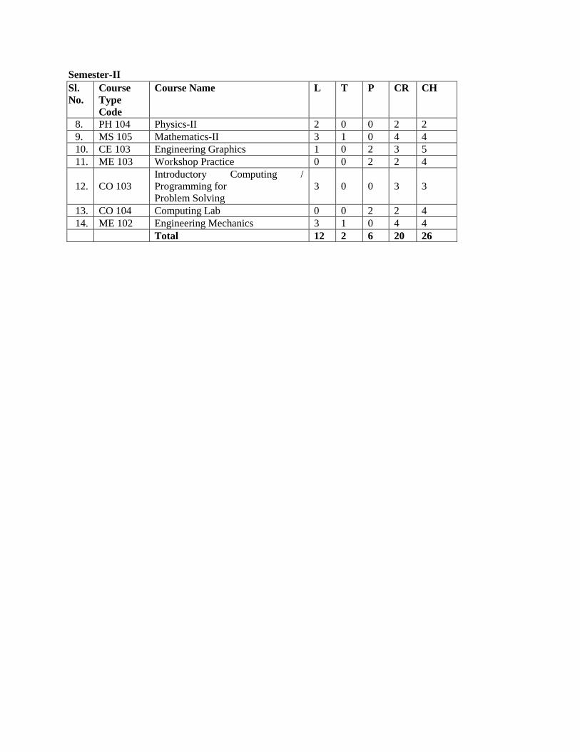
Semester-II
Sl.
No.
Course
Type
Code
Course Name L T P CR CH
8. PH 104 Physics-II 2 0 0 2 2
9. MS 105 Mathematics-II 3 1 0 4 4
10. CE 103 Engineering Graphics 1 0 2 3 5
11. ME 103 Workshop Practice 0 0 2 2 4
12. CO 103
Introductory Computing /
Programming for
Problem Solving
3 0 0 3 3
13. CO 104 Computing Lab 0 0 2 2 4
14. ME 102 Engineering Mechanics 3 1 0 4 4
Total 12 2 6 20 26
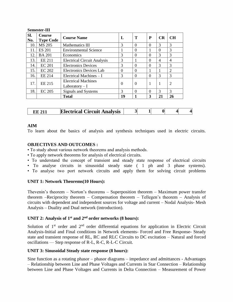
Semester-III
Sl.
No.
Course
Type Code Course Name L T P CR CH
10. MS 205 Mathematics III 3 0 0 3 3
11. ES 201 Environmental Science 1 0 1 0 3
12. BA 201 Economics 3 0 0 3 3
13. EE 211 Electrical Circuit Analysis 3 1 0 4 4
14. EC 201 Electronics Devices 3 0 0 3 3
15. EC 202 Electronics Devices Lab 0 0 1 1 2
16. EE 214 Electrical Machines – I 3 0 0 3 3
17. EE 215 Electrical Machines
Laboratory – I 0 0 1 1 2
18. EC 205 Signals and Systems 3 0 0 3 3
Total 19 1 3 21 26
EE 211 Electrical Circuit Analysis 3 1 0 4 4
AIM
To learn about the basics of analysis and synthesis techniques used in electric circuits.
OBJECTIVES AND OUTCOMES :
• To study about various network theorems and analysis methods.
• To apply network theorems for analysis of electrical circuits.
• To understand the concept of transient and steady state response of electrical circuits
• To analyse circuits in sinusoidal steady state ( 1 ph and 3 phase systems).
• To analyse two port network circuits and apply them for solving circuit problems
UNIT 1: Network Theorems(10 Hours):
Thevenin’s theorem – Norton’s theorems – Superposition theorem – Maximum power transfer
theorem –Reciprocity theorem – Compensation theorem – Tellegen’s theorem – Analysis of
circuits with dependent and independent sources for voltage and current – Nodal Analysis- Mesh
Analysis – Duality and Dual network (introduction).
UNIT 2: Analysis of 1st and 2nd order networks (8 hours):
Solution of 1st order and 2nd order differential equations for application in Electric Circuit
Analysis-Initial and Final conditions in Network elements- Forced and Free Response- Steady
state and transient response of RL, RC and RLC Circuits to DC excitation – Natural and forced
oscillations –– Step response of R-L, R-C, R-L-C Circuit.
UNIT 3: Sinusoidal Steady state response (8 hours):
Sine function as a rotating phasor – phasor diagrams – impedance and admittances - Advantages
– Relationship between Line and Phase Voltages and Currents in Star Connection – Relationship
between Line and Phase Voltages and Currents in Delta Connection – Measurement of Power

and Power Factor of a Balanced Three Phase Load – Unbalanced Loads- Self and Mutual
Inductance – Coefficient of Coupling – Series Connection of Coupled Circuits – Modelling –
Dot Convention – Electrical Equivalents of Magnetically Coupled Circuits.
UNIT 4: Laplace Transform and its application in Electrical Circuit Analysis (8 hours):
Basics of Laplace transform – inverse Laplace transform – Convolution integral – transformed
network with initial conditions – transfer function representation – poles and zeros – frequency
response, series and parallel resonance.
UNIT 5: Two port networks (6 hours):
Network Elements – Classification of Network – Network Configuration – Parameters and
Transfer Function – Z, Y, hybrid, ABCD parameters – Condition for Reciprocity and Symmetry
– Inter-relationships between Parameters of Two-Port Networks – Types of Interconnections:
series, parallel and cascaded.
TEXT BOOKS:
1. William H. Hayt and Jack E. Kemmerly, “Engineering Circuit Analysis”, McGraw-Hill
International Edition.2013.
2. A. Chakrabarti, “Circuit Theory”, Dhanpat Rai & Co. Pvt. Ltd. 2010.
3. Van Valkenburg, “Network Analysis”, Prentice Hall of India Pvt. Ltd., 2006.
4. C.K. Alexander and M.N. O. Sadiku, “Electric Circuits”, McGraw Hill Education, 2004.
REFERENCE BOOKS:
1. Joseph A Edminister “Electric Circuits”, Third Edition, Tata McGraw-Hill
2. M L Soni and J C Gupta “A Course in Electrical Circuits Analysis” Dhanpat Rai Publications
EC 201 Electronics devices 3 0 0 3 3
Introduction to Semiconductor Physics: Review of Quantum Mechanics, Electrons in
periodicLattices, E-k diagrams. Energy bands in intrinsic and extrinsic silicon; Carrier
transport:diffusion current, drift current, mobility and resistivity; sheet resistance, design of
resistors.
Generation and recombination of carriers; Poisson and continuity equation P-N
junctioncharacteristics, I-Vcharacteristics, and small signal switching models; Avalanche
breakdown,Zener diode, Schottky diode.
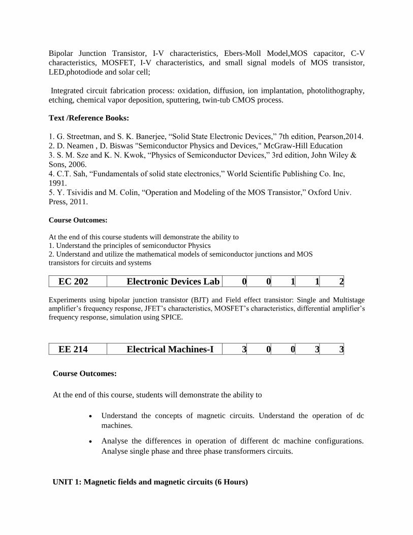
Bipolar Junction Transistor, I-V characteristics, Ebers-Moll Model,MOS capacitor, C-V
characteristics, MOSFET, I-V characteristics, and small signal models of MOS transistor,
LED,photodiode and solar cell;
Integrated circuit fabrication process: oxidation, diffusion, ion implantation, photolithography,
etching, chemical vapor deposition, sputtering, twin-tub CMOS process.
Text /Reference Books:
1. G. Streetman, and S. K. Banerjee, “Solid State Electronic Devices,” 7th edition, Pearson,2014.
2. D. Neamen , D. Biswas "Semiconductor Physics and Devices," McGraw-Hill Education
3. S. M. Sze and K. N. Kwok, “Physics of Semiconductor Devices,” 3rd edition, John Wiley &
Sons, 2006.
4. C.T. Sah, “Fundamentals of solid state electronics,” World Scientific Publishing Co. Inc,
1991.
5. Y. Tsividis and M. Colin, “Operation and Modeling of the MOS Transistor,” Oxford Univ.
Press, 2011.
Course Outcomes:
At the end of this course students will demonstrate the ability to
1. Understand the principles of semiconductor Physics
2. Understand and utilize the mathematical models of semiconductor junctions and MOS
transistors for circuits and systems
EC 202 Electronic Devices Lab 0 0 1 1 2
Experiments using bipolar junction transistor (BJT) and Field effect transistor: Single and Multistage
amplifier’s frequency response, JFET’s characteristics, MOSFET’s characteristics, differential amplifier’s
frequency response, simulation using SPICE.
EE 214 Electrical Machines-I 3 0 0 3 3
Course Outcomes:
At the end of this course, students will demonstrate the ability to
Understand the concepts of magnetic circuits. Understand the operation of dc
machines.
Analyse the differences in operation of different dc machine configurations.
Analyse single phase and three phase transformers circuits.
UNIT 1: Magnetic fields and magnetic circuits (6 Hours)

Review of magnetic circuits - MMF, flux, reluctance, inductance; review of Ampere Law and Biot Savart Law; Visualization of magnetic fields produced by a bar magnet and a current carrying coil - through air and through a combination of iron and air; influence of highly permeable materials on the magnetic flux lines.
UNIT 2: Electromagnetic force and torque (9 Hours)
B-H curve of magnetic materials; flux-linkage vs current characteristic of magnetic circuits; linear and nonlinear magnetic circuits; energy stored in the magnetic circuit; force as a partial
derivative of stored energy with respect to position of a moving element; torque as a partial derivative of stored energy with respect to angular position of a rotating element. Examples - galvanometer coil, relay contact, lifting magnet, rotating element with eccentricity or saliency
UNIT 3: DC machines (8 Hours)
Basic construction of a DC machine, magnetic structure - stator yoke, stator poles, pole-faces
or shoes, air gap and armature core, visualization of magnetic field produced by the field
winding excitation with armature winding open, air gap flux density distribution, flux per pole,
induced EMF in an armature coil. Armature winding and commutation - Elementary armature
coil and commutator, lap and wave windings, construction of commutator, linear commutation
Derivation of back EMF equation, armature MMF wave, derivation of torque equation,
armature reaction, air gap flux density distribution with armature reaction.
UNIT 4: DC machine - motoring and generation (7 Hours)
Armature circuit equation for motoring and generation, Types of field excitations - separately excited, shunt and series. Open circuit characteristic of separately excited DC generator, back EMF with armature reaction, voltage build-up in a shunt generator, critical field resistance and critical speed. V-I characteristics and torque-speed characteristics of separately excited, shunt and series motors. Speed control through armature voltage. Losses, load testing and back-to-back testing of DC machines
UNIT 5: Transformers (12 Hours) Principle, construction and operation of single-phase transformers, equivalent circuit, phasor
diagram, voltage regulation, losses and efficiency Testing - open circuit and short circuit tests, polarity test, back-to-back test, separation of hysteresis and eddy current losses Three-phase
transformer - construction, types of connection and their comparative features, Parallel operation of single-phase and three-phase transformers, Autotransformers - construction,
principle, applications and comparison with two winding transformer, Magnetizing current,
effect of nonlinear B-H curve of magnetic core material, harmonics in magnetization current, Phase conversion - Scott connection, three-phase to six-phase conversion, Tap-changing
transformers - No-load and on-load tap-changing of transformers, Three-winding transformers. Cooling of transformers.
Text / References:
1. A. E. Fitzgerald and C. Kingsley, "Electric Machinery”, New York, McGraw Hill Education, 2013.
2. A. E. Clayton and N. N. Hancock, “Performance and design of DC machines”, CBS Publishers, 2004.
3. M. G. Say, “Performance and design of AC machines”, CBS Publishers, 2002. 4. P. S. Bimbhra, “Electrical Machinery”, Khanna Publishers, 2011. 5. I. J. Nagrath and D. P. Kothari, “Electric Machines”, McGraw Hill Education, 2010.
EE 215 Electrical Machines
Laboratory-I
0 0 2 1 2
Hands-on experiments related to the course contents of EE 214.
EC 205 Signals and Systems 3 0 0 3 3
Signals and systems as seen in everydaylife, and in various branches of engineering and science.
Energy and power signals, continuous and discrete time signals, continuous and discrete
amplitude signals. System properties: linearity: additivity and homogeneity, shift-invariance,
causality, stability, realizability.
Linear shift-invariant (LSI) systems, impulse response and step response, convolution, input-
output behavior with aperiodic convergent inputs. Characterization of causality and stability of
linear shift-invariant systems. System representation through differential equations and
difference equations.
Periodic and semi-periodic inputs to an LSI system, the notion of a frequencyresponse and its
relation to the impulse response, Fourier series representation, the Fourier Transform,
convolution/multiplication and their effect in the frequency domain, magnitude and phase
response, Fourier domain duality. The Discrete-Time Fourier Transform (DTFT) and the
Discrete Fourier Transform (DFT). Parseval's Theorem.The idea of signal space and orthogonal
bases,
The Laplace Transform, notion ofeigen functions of LSI systems, a basis of eigen functions,
region of convergence, poles and zeros of system, Laplace domain analysis, solution to
differential equations and system behavior.
The z-Transform for discrete time signals and systems- eigen functions, region of convergence,
z-domain analysis.
State-space analysis and multi-input, multi-output representation. The state-transition matrix and
its role. The Sampling Theorem and its implications- Spectra of sampled signals.
Reconstruction: ideal interpolator, zero-order hold, first-order hold, and so on. Aliasing and its
effects. Relation between continuous and discrete time systems.

Text/Reference books:
1. A.V. Oppenheim, A.S. Willsky and I.T. Young, "Signals and Systems", Prentice Hall,
1983.
2. R.F. Ziemer, W.H. Tranter and D.R. Fannin, "Signals and Systems - Continuous and
Discrete", 4th edition, Prentice Hall, 1998.
3. Papoulis, "Circuits and Systems: A Modern Approach", HRW, 1980.
4. B.P. Lathi, "Signal Processing and Linear Systems", Oxford University Press, c1998.
5. Douglas K. Lindner, "Introduction to Signals and Systems", McGraw Hill International
Edition: c1999.
6. Simon Haykin, Barry van Veen, "Signals and Systems", John Wiley and Sons (Asia)
Private Limited, c1998. 7. Robert A. Gabel, Richard A. Roberts, "Signals and Linear Systems", John Wiley and Sons, 1995. 8. M. J. Roberts, "Signals and Systems - Analysis using Transform methods and MATLAB", TMH, 2003. 9. J. Nagrath, S. N. Sharan, R. Ranjan, S. Kumar, "Signals and Systems", TMH New Delhi, 2001. 10. Ashok Ambardar,"Analog and Digital Signal Processing", 2nd Edition, Brooks/ Cole Publishing Company (An international Thomson Publishing Company), 1999.
Course outcomes:
At the end of this course students will demonstrate the ability to
1. Analyze different types of signals 2. Represent continuous and discrete systems in time and frequency domain using different
transforms 3. Investigate whether the system is stable
4. Sampling and reconstruction of a signal
Semester-IV
Sl.
No.
Course
Type
Code
Course Name L T P CR CH
10. BT 201 Biology 3 0 0 3 3
11. EE 217 Digital Electronics 3 0 0 3 3
12. EE 218 Digital Electronics Laboratory
0 0 1 1 2
13. EE 219 Electrical Machines – II 3 0 0 3 3
14. EE 220 Electrical Machines Laboratory –
II 0 0 1 1 2
15. EC211 Microcontroller and
Microprocessor 3 0 0 3 3
16. EC212 Microcontroller Lab 0 0 1 1 2

17. EE 216 Electromagnetic Fields 3 1 0 4 4
18. *Open Elective-1 3 0 0 3 3
Total 18 1 3 22 25
*For Open Elective – 1: Any course offered by the University from the preferable subjects enlisted in
Table A. and recommended by the department, as per AICTE guidelines.
EE 217 Digital Electronics 3 0 0 3 3
CourseOutcomes: At the end of this course, students will demonstrate the ability to
Understand working of logic families and logic gates. Design and implement Combinational and Sequential logiccircuits. Understand the process of Analog to Digital conversion and Digital to Analog
conversion. Be able to use PLDs to implement the given logical problem.
UNIT 1:Fundamentals of Digital Systems and logicfamilies (7Hours) Digital signals, digital circuits, AND, OR, NOT, NAND, NOR and Exclusive-OR operations, Boolean algebra, examples ofICgates, number systems-binary, signed binary, octal hexadecimal number, binaryarithmetic,one’s and two’s complements arithmetic, codes, error detecting and correctingcodes,characteristics of digital ICs, digital logic families, TTL, Schottky TTL and CMOS logic, interfacing CMOS and TTL, Tri-statelogic.
UNIT 2: Combinational DigitalCircuits (7Hours) Standard representation for logic functions, K-map representation, simplification oflogicfunctions using K-map, minimization of logical functions. Don’t care conditions,
Multiplexer,De-Multiplexer/Decoders, Adders, Subtractors, BCD arithmetic, carry look
ahead adder,serialadder, ALU, elementary ALU design, popular MSI chips, digital comparator,paritychecker/generator, code converters, priority encoders, decoders/drivers for
display devices,Q-M method of functionrealization.
UNIT 3: Sequential circuits and systems (7Hours) A 1-bit memory, the circuit properties of Bistable latch, the clocked SR flip flop, J- K-T AndD-
typesflipflops,applicationsofflipflops,shiftregisters,applicationsofshiftregisters,serialtoparallel
converter, parallelto serial converter, ringcounter, sequence
generator,ripple(Asynchronous) counters, synchronous counters, counters design using flip flops,specialcounter IC’s, asynchronous sequential counters, applications ofcounters.
UNIT 4: A/D and D/A Converters (7Hours) Digital to analog converters: weighted resistor/converter, R-2R Ladder D/Aconverter,specifications for D/A converters, examples of D/A converter lCs, sample and hold circuit,analog to digital converters: quantization and encoding, parallel comparator A/Dconverter,successive approximation A/D converter, counting A/D
converter, dual slope A/Dconverter,A/Dconverterusing
voltagetofrequencyandvoltagetotimeconversion,specificationsofA/Dconverters, example of A/D
converterICs
UNIT 5: Semiconductor memories and Programmable logic devices. (7Hours) Memory
organization and operation, expanding memory size, classification andcharacteristicsof memories,
sequential memory, read only memory (ROM), read and write memory(RAM), content
addressable memory (CAM), charge de coupled device memory (CCD), commonly used memory
chips, ROM as a PLD, Programmable logic array, Programmable array logic, complex
Programmable logic devices (CPLDS), Field Programmable Gate Array (FPGA).
Text/References:
1. R. P. Jain, "Modern Digital Electronics", McGraw Hill Education, 2009.
2. M. M. Mano, "Digital logic and Computer design", Pearson Education India, 2016.
3. A. Kumar, "Fundamentals of Digital Circuits", Prentice Hall India, 2016.
EE 218
Digital
ElectronicsLaboratory
0 0 1 1 2
Hands-on experiments related to the course contents of EE07.
EE 219 Electrical Machines – II 3 0 0 3 3
Course Outcomes: At the end of this course, students will demonstrate the ability to
Understand the concepts of rotating magnetic fields.
Understand the operation of ac machines. Analyse performance characteristics of ac machines.
UNIT 1: Fundamentals of AC machine windings (8 Hours)
Physical arrangement of windings in stator and cylindrical rotor; slots for windings; single turn
coil - active portion and overhang; full-pitch coils, concentrated winding, distributed winding,
winding axis, 3D visualization of the above winding types, Air-gap MMF distribution with fixed
current through winding - concentrated and distributed, sinusoidally distributed winding,
winding distribution factor
UNIT 2: Pulsating and revolving magnetic fields (4 Hours)
Constant magnetic field, pulsating magnetic field - alternating current in windings with spatial
displacement, Magnetic field produced by a single winding - fixed current and alternating current

Pulsating fields produced by spatially displaced windings, Windings spatially shifted by 90
degrees, Addition of pulsating magnetic fields, Three windings spatially shifted by 120 degrees
(carrying three-phase balanced currents), revolving magnetic field.
UNIT 3: Induction Machines (12 Hours)
Construction, Types (squirrel cage and slip-ring), Torque Slip Characteristics, Starting and
Maximum Torque, Equivalent circuit, phasor Diagram, Losses and Efficiency, Effect of
parameter variation on torque speed characteristics (variation of rotor and stator resistances,
stator voltage, frequency), Methods of starting, braking and speed control for induction motors,
Generator operation, Self-excitation, Doubly-Fed Induction Machines.
UNIT 4: Single-phase induction motors (6 Hours)
Constructional features, double revolving field theory, equivalent circuit, determination of
parameters. Split-phase starting methods and applications
UNIT 5: Synchronous machines (10 Hours)
Constructional features, cylindrical rotor synchronous machine - armature reaction, generated
EMF, equivalent circuit and phasor diagram, synchronous impedance, open circuit characteristic,
short circuit characteristics, Zero power factor characteristics; Potier Triangle; voltage
regulation, Salient pole machine – two reaction theory, analysis of phasor diagram, Power flow
equation, power angle characteristics, Parallel operation of alternators - synchronization and load
division, Effect of change of excitation and mechanical input, Generator capability curve.
Starting of synchronous motor, Damper winding, Operating characteristics of synchronous
machines, Effect of variation of field excitation and load; Mechanical Power, V and Inverted V
curves, Hunting.
Text/References:
1. P. S. Bimbhra, “Electrical Machinery”, Khanna Publishers, 2011.
2. A. E. Fitzgerald and C. Kingsley, "Electric Machinery”, McGraw Hill Education, 2013.
3. M. G. Say, “Performance and design of AC machines”, CBS Publishers, 2002.
4. I. J. Nagrath and D. P. Kothari, “Electric Machines”, McGraw Hill Education, 2010.
5. A. S. Langsdorf, “Alternating current machines”, McGraw Hill Education, 1984.
6. P. C. Sen, “Principles of Electric Machines and Power Electronics”, John Wiley & Sons,
2007.
EE 220
Electrical
MachinesLaboratory –
II
0 0 1 1 3
Hands-on experiments related to the course contents of EE 219
EC 211
Microcontroller and
Microprocessor
3 0 0 3 3
Overview of microcomputer systems and their building blocks, memory interfacing, concepts of
interrupts and Direct Memory Access, instruction sets of microprocessors (with examples of 8085 and
8086);
Interfacing with peripherals - timer, serial I/O, parallel I/O, A/D and D/A converters; Arithmetic
Coprocessors; System level interfacing design;
Concepts of virtual memory, Cache memory, Advanced co-processor Architectures- 286, 486, Pentium; Microcontrollers: 8051 systems,
Introduction to RISC processors; ARM microcontrollers interface designs.
Text/Reference Books:
1. R. S. Gaonkar, Microprocessor Architecture: Programming and Applications with the 8085/8080A, Penram International Publishing, 1996
2. D A Patterson and J H Hennessy, "Computer Organization and Design The hardware and
software interface. Morgan Kaufman Publishers.
3. Douglas Hall, Microprocessors Interfacing, Tata McGraw Hill, 1991.
4. Kenneth J. Ayala, The 8051 Microcontroller, Penram International Publishing, 1996.
Course Outcomes:
At the end of this course students will demonstrate the ability to
1. Do assembly language programming
2. Do interfacing design of peripherals like, I/O, A/D, D/A, timer etc.
3. Develop systems using different microcontrollers
4. Understand RSIC processors and design ARM microcontroller based systems
EC 212 Microcontroller Lab 0 0 1 1 2 Assembly language programming for 8085/8086: interfacing of 8085/8086: memory
interfacing. Design of I/O modules and interfacing of different peripherals, parallel
interfacing using A/D and D/A converters; 8051 based control of stepper motor.
Programming in Ardino UNO, peak and arm processor
EE 216 Electromagnetic Fields 3 1 0 4 4
Course Outcomes: At the end of the course, students will demonstrate the ability
To understand the basic laws of electromagnetism. To obtain the electric and magnetic fields for simple configurations under static
conditions. To analyse time varying electric and magnetic fields. To understand Maxwell’s equation in different forms and different media.
To understand the propagation of EM waves.
This course shall have Lectures and Tutorials. Most of the students find difficult to visualize
electric and magnetic fields. Instructors may demonstrate various simulation tools to visualize electric and magnetic fields in practical devices like transformers, transmission lines and machines.
UNIT 1: Review of Vector Calculus (6 hours) Vectoralgebra-addition,subtraction, Componentsofvectors,scalarandvectormultiplications,tripleproducts, Threeorthogonalcoordinatesystems (rectangular, cylindrical and spherical). Vectorcalculus-
differentiation,partialdifferentiation,integration,vector operatordel,gradient, divergence
andcurl;integraltheoremsofvectors. Conversionofavectorfromonecoordinatesystemtoanother.
UNIT 2: Static Electric Field (6 Hours) Coulomb’s law, Electric field intensity, Electrical field due to point charges. Line, Surface and Volume charge distributions. Gauss law and its applications. Absolute Electric potential, Potential difference, Calculation of potential differences for different configurations. Electric dipole, Electrostatic Energy and Energy density.
UNIT 3: Conductors, Dielectrics and Capacitance (6 Hours) Current and current density, Ohms Law in Point form, Continuity of current, Boundary conditions of perfect dielectric materials. Permittivity of dielectric materials, Capacitance, Capacitance of a two wire line, Poisson’s equation, Laplace’s equation, Solution of Laplace and Poisson’s equation, Application of Laplace’s and Poisson’s equations.
UNIT 4: Static Magnetic Fields (6 Hours) Biot-Savart Law, Ampere Law, Magnetic flux and magnetic flux density, Scalar and Vector Magnetic potentials. Steady magnetic fields produced by current carrying conductors.
UNIT 5: Magnetic Forces, Materials and Inductance (6 Hours) Force on a moving charge, Force on a differential current element, Force between differential current elements, Nature of magnetic materials, Magnetization and permeability, Magnetic boundary conditions, Magnetic circuits, inductances and mutual inductances.
UNIT 6: Time Varying Fields and Maxwell’s Equations (6 Hours)
Faraday’s law for Electromagnetic induction, Displacement current, Point form of Maxwell’s equation, Integral form of Maxwell’s equations, Motional Electromotive forces. Boundary Conditions.
UNIT 7: Electromagnetic Waves (6 Hours) Derivation of Wave Equation, Uniform Plane Waves, Maxwell’s equation in Phasor form, Wave equation in Phasor form, Plane waves in free space and in a homogenous material. Wave equation for a conducting medium, Plane waves in lossy dielectrics, Propagation in good conductors, Skin effect. Poynting theorem.
Text / References: 1. M. N. O. Sadiku, “Elements of Electromagnetics”, Oxford University Publication, 2014. 2. A. Pramanik, “Electromagnetism - Theory and applications”, PHI Learning Pvt. Ltd, New
Delhi, 2009. 3. A. Pramanik, “Electromagnetism-Problems with solution”, Prentice Hall India, 2012. 4. G. W. Carter, “The electromagnetic field in its engineering aspects”, Longmans, 1954. 5. W. J. Duffin, “Electricity and Magnetism”, McGraw Hill Publication, 1980. 6. W. J. Duffin, “Advanced Electricity and Magnetism”, McGraw Hill, 1968. 7. E. G. Cullwick, “The Fundamentals of Electromagnetism”, Cambridge University Press, 1966. 8. B. D. Popovic, “Introductory Engineering Electromagnetics”, Addison-Wesley Educational Publishers, International Edition, 1971. 9. W. Hayt, “Engineering Electromagnetics”, McGraw Hill Education, 2012.

Semester-V
Sl.
No.
Course
Type Code
Course Name L T P CR CH
10. EE 311
Power Systems – I (Apparatus
and Modelling) 3 0 0 3 3
11. EE 312
Power Systems
Laboratory – I 0 0 1 1 2
12. EE 313 Control Systems 3 0 0 3 3
13. EE 314 Control Systems Laboratory 0 0 1 1 2
14. EE 315 Power Electronics 3 0 0 3 3
15. EE 316 Power Electronics Laboratory 0 0 1 1 2
16. Program Elective – 1 3 0 0 3 3
17. *Open Elective – 2 3 0 0 3 3
18. LW 301 Indian Constitution 1 0 0 0 1
Total 16 0 3 18 22
For Program Elective – 1
EE317 Electrical Machine Design
*For Open Elective – 2:Any course offered by the University from the preferable subjects enlisted in
Table A. and recommended by the department, as per AICTE guidelines.
EE 311 Power Systems-I 3 0 0 3 3
Course Outcomes: At the end of this course, students will demonstrate the ability to
Understand the concepts of power systems. Understand the various power system components.
Evaluate fault currents for different types of faults. Understand the generation of over-voltages and insulation coordination.
Understand basicprotection schemes. Understand concepts of HVdc power transmission and renewable energy generation.
UNIT 1: Basic Concepts (4 hours)
Evolution of Power Systems and Present-Day Scenario. Structure of a power system: Bulk
Power Grids and Micro-grids.
Generation: Conventional and Renewable Energy Sources. Distributed Energy Resources.
Energy Storage. Transmission and Distribution Systems: Line diagrams, transmission and
distribution voltage levels and topologies (meshed and radial systems). Synchronous Grids and
Asynchronous (DC) interconnections. Review of Three-phase systems. Analysis of simple three-
phase circuits. Power Transfer in AC circuits and Reactive Power.
UNIT 2: Power System Components (15 hours)
Overhead Transmission Lines and Cables: Electrical and Magnetic Fields around conductors,
Corona. Parameters of lines and cables. Capacitance and Inductance calculations for simple
configurations. Travelling-wave Equations. Sinusoidal Steady state representation of Lines:
Short, medium and long lines. Power Transfer, Voltage profile and Reactive Power.
Characteristics of transmission lines. Surge Impedance Loading. Series and Shunt Compensation
of transmission lines.
Transformers: Three-phase connections and Phase-shifts. Three-winding transformers,
autotransformers, Neutral Grounding transformers. Tap-Changing in transformers. Transformer
Parameters. Single phase equivalent of three-phase transformers.
Synchronous Machines: Steady-state performance characteristics. Operation when connected to
infinite bus. Real and Reactive Power Capability Curve of generators. Typical waveform under
balanced terminal short circuit conditions – steady state, transient and sub-transient equivalent
circuits. Loads: Types, Voltage and Frequency Dependence of Loads. Per-unit System and per-
unit calculations.
UNIT 3: Over-voltages and Insulation Requirements (4 hours)
Generation of Over-voltages: Lightning and Switching Surges. Protection against Overvoltages,
Insulation Coordination. Propagation of Surges. Voltages produced by traveling surges. Bewley
Diagrams.
UNIT 4: Fault Analysis and Protection Systems (10 hours)
Method of Symmetrical Components (positive, negative and zero sequences). Balanced and
Unbalanced Faults. Representation of generators, lines and transformers in sequence networks.
Computation of Fault Currents. Neutral Grounding. Switchgear: Types of Circuit Breakers.
Attributes of Protection schemes, Back-up Protection. Protection schemes (Over-current,
directional, distance protection, differential protection) and their application.
UNIT 5: Introduction to DC Transmission & Renewable Energy Systems (9 hours)
DC Transmission Systems: Line-Commutated Converters (LCC) and Voltage Source Converters
(VSC). LCC and VSC based dc link, Real Power Flow control in a dc link. Comparison of ac
and dc transmission. Solar PV systems: I-V and P-V characteristics of PV panels, power
electronic interface of PV to the grid. Wind Energy Systems: Power curve of wind turbine. Fixed
and variable speed turbines. Permanent Magnetic Synchronous Generators and Induction
Generators. Power Electronics interfaces of wind generators to the grid.
Text/References:
1. J. Grainger and W. D. Stevenson, “Power System Analysis”, McGraw Hill Education, 1994.
2. O. I. Elgerd, “Electric Energy Systems Theory”, McGraw Hill Education, 1995.
3. A. R. Bergen and V. Vittal, “Power System Analysis”, Pearson Education Inc., 1999.
4. D. P. Kothari and I. J. Nagrath, “Modern Power System Analysis”, McGraw Hill
Education, 2003.
5. B. M. Weedy, B. J. Cory, N. Jenkins, J. Ekanayake and G. Strbac, “Electric Power
Systems”, Wiley, 2012.
6. C. L.Wadhwa, Electrical Power System ,New Age Intl. (P) Ltd., 2005, 4th edition.
EE 312 Power Systems- 0 0 1 1 2
ILaboratory
Hands-on experiments related to the course contents of EE 311. Visits to power system
installations (generation stations, EHV substations etc.) are suggested. Exposure to fault analysis
and Electro-magnetic transient program (EMTP) and Numerical Relays are suggested.
EE 313 Control Systems 3 0 0 3 3
Course Outcomes: At the end of this course, students will demonstrate the ability to
Understand the modellingof linear-time-invariant systems using transfer function and state-space representations. Understandthe concept of stability and its assessment for linear-time invariant systems.
Design simple feedback controllers.
UNIT 1: Introduction to control problem (4 hours) Industrial Control examples. Mathematical models of physical systems. Control hardware and their models. Transfer function models of linear time-invariant systems. Feedback Control: Open-Loop and Closed-loop systems. Benefits of Feedback. Block diagram algebra.
UNIT 2: Time Response Analysis (10 hours) Standard test signals. Time response of first and second order systems for standard test inputs. Application of initial and final value theorem. Design specifications for second-order systems based on the time-response.
Concept of Stability. Routh-Hurwitz Criteria. Relative Stability analysis. Root-Locus technique. Construction of Root-loci.
UNIT 3: Frequency-response analysis (6 hours) Relationship between time and frequency response, Polar plots, Bode plots. Nyquist stability criterion. Relative stability using Nyquist criterion – gain and phase margin. Closed-loop frequency response.
UNIT 4: Introduction to Controller Design (10 hours) Stability, steady-state accuracy, transient accuracy, disturbance rejection, insensitivity and robustness of control systems. Root-loci method of feedback controller design. Design specifications in frequency-domain. Frequency-domain methods of design. Application of Proportional, Integral and Derivative Controllers, Lead and Lag compensation in designs. Analog and Digital implementation of controllers.
UNIT 5: State variable Analysis (6 hours)
Concepts of state variables. State space model. Diagonalization of State Matrix. Solution of state equations. Eigenvalues and Stability Analysis. Concept of controllability and observability. Pole-placement by state feedback. Discrete-time systems. Difference Equations. State-space models of linear discrete-time
systems. Stability of linear discrete-time systems
UNIT 6: Introduction to Optimal Control and NonlinearControl(5 hours)
Performance Indices. Regulator problem, Tracking Problem. Nonlinear system–Basic concepts
and analysis.
Text/References: 1. M. Gopal, “Control Systems: Principles and Design”, McGraw Hill Education, 1997. 2. B. C. Kuo, “Automatic Control System”, Prentice Hall, 1995. 3. K. Ogata, “Modern Control Engineering”, Prentice Hall, 1991. 4. I. J. Nagrath and M. Gopal, “Control Systems Engineering”, New Age International, 2009
EE 314 Control SystemsLaboratory 0 0 1 1 2
Hands-on/Computer experiments related to the course contents of EE 313.
EE 315 Power Electronics 3 0 0 3 3
Aim: The course discusses introductory topics in power electronics for the UG level students of electrical
engineering
Course Outcomes: At the end of this course students will demonstrate the ability to
Understand the differences between signal level and power level devices.
Analyse controlled rectifier circuits. Analyse the operation of DC-DC choppers. Analyse the operation of voltage source inverters.
UNIT I: Power Switching Devices : (8 Hours):
Power Diodes – General Purpose, Fast Recovery, Schottky Diode; BJT, MOSFET, SCR, IGBT
and their V-I characteristics; SCR: Operating Principle, Gate Characteristics, Two-Transistor
model, di/dt and dv/dt Protection, Firing circuits, series and parallel operation, rating, selection;
Thyristor Triggering techniques; Thyristor Commutation techniques; Snubber circuits. Gate
Drives for MOSFET and IGBT
UNIT II: Thyristor Rectifiers (8 hours):
1-ɸ and 3-ɸ semi, half-wave, dual and full-wave controlled rectifiers with R and RL loads;
freewheeling diode; detailed derivation of rms, average value, harmonic factor, THD, crest
factor; half wave and full wave controlled rectifiers; Input current wave shape and power factor
Effect of Source impedance.
UNIT III: DC-DC Converters (10 Hours):
Principle; Elementary step-up and step-down choppers; concept of duty ratio and average voltage
classification; power circuits of buck, boost and buck- boost converters, analysis and waveforms
at steady state; control of duty ratio and the output; CCM and DCM modes of operation.
UNIT IV: DC-AC Converters/Inverter (single phase) (10 Hours):
Power Circuits of single-phase voltage source inverter; Concepts of switched mode inverters;
Square wave operation; PWM switching; Series and parallel inverters; Convept of average
voltage over a switching cycle; modulation; modulation index; modulation techniques.
UNIT V: DC-AC Converters/Inverter (Three phase) (8 Hours):
3-ɸ half bridge and full bridge inverter with R and RL loads; 120° & 180° degree conduction;
harmonics reduction; Three phase sinusoidal modulation; Current source inverter; Zero current
switching (ZCS); Zero voltage Switching (ZVS); Introduction of resonant inverters.
TEXT BOOKS:
1. Muhammad Rashid, Power Electronics- Circuits, Devices and Applications, 3/e, Pearson
Education India 2009.
2. N. Mohan and T.M. Undeland, Power Electronics – Converters, Applications and Design,
John Wiley & Sons, 2007.
REFERENCES:
1. B. K. Bose, Modern Power Electronics and AC Drives, Pearson Education, 2003.
2. R.W. Erickson and D. Maksimovic, Fundamentals of Power Electronics, Springer
Science and Business Media, 2007.
3. G. K. Dubey, Fundamentals of Electrical Drives, Narosa Publishing House, 2003.
4. L. Umanand, Power Electronics: Essential and Applications, Wiley, India, 2009.
EE 316
Power
ElectronicsLaboratory
0 0 1 1 2
Hands-on experiments related to the course contents of EE 315
--------------------------------------------------------------------------------------------------------------
EE 317 Electrical Machine Design 3L:0T:0P 3 credits
Course Outcomes: At the end of this course, students will demonstrate the ability to
Understand the constructionand performance characteristics of electrical machines.
Understand the various factors which influence the design: electrical, magnetic and thermal loading of electrical machines
Understand the principles of electrical machine design and carry out a basic design of an ac machine.
Use software tools to do design calculations.
UNIT 1: Introduction Major considerations in electrical machine design, electrical engineering materials, space factor, choice of specific electrical and magnetic loadings, thermal considerations, heat flow, temperature rise, rating of machines.
UNIT 2: Transformers Sizing of a transformer, main dimensions, kVA output for single- and three-phase transformers, window space factor, overall dimensions, operating characteristics, regulation, no load current, temperature rise in transformers, design of cooling tank, methods for cooling of transformers.
UNIT 3: Induction Motors Sizing of an induction motor, main dimensions, length of air gap, rules for selecting rotor slots of squirrel cage machines, design of rotor bars & slots, design of end rings, design of wound rotor, magnetic leakage calculations, leakage reactance of polyphase machines, magnetizing current, short circuit current, circle diagram, operating characteristics.
UNIT 4: Synchronous Machines Sizing of a synchronous machine, main dimensions, design of salient pole machines, short circuit ratio, shape of pole face, armature design, armature parameters, estimation of air gap length, design of rotor, design of damper winding, determination of full load field mmf, design of field winding, design of turbo alternators, rotor design. UNIT 5: Computer aided Design (CAD): Limitations (assumptions) of traditional designs, need for CAD analysis, synthesis and hybrid methods, design optimization methods, variables, constraints and objective function, problem formulation. Introduction to FEM based machine design. Introduction to complex structures of modern machines-PMSMs, BLDCs, SRM and claw-pole machines.
Text / References: 1. A. K. Sawhney, “A Course in Electrical Machine Design”, Dhanpat Rai and Sons, 1970.
2. M.G. Say, “Theory & Performance & Design of A.C. Machines”, ELBS London. 3. S. K. Sen, “Principles of Electrical Machine Design with computer programmes”, Oxford and IBH Publishing, 2006
4. K. L. Narang, “A Text Book of Electrical Engineering Drawings”, SatyaPrakashan, 1969.
5. A. Shanmugasundaram, G. Gangadharan and R. Palani, “Electrical Machine Design Data Book”, New Age International, 1979.
6. K. M. V. Murthy, “Computer Aided Design of Electrical Machines”, B.S. Publications, 2008.
7. Electrical machines and equipment design exercise examples using Ansoft’s Maxwell 2D machine design package

Semester-VI
Sl.
No.
Course Type
Code
Course Name L T P CR CH
10. IC 361 Accounting & Financial
Management 3 0 0 3 3
11. EE 318 Power Systems – II (Operation
and Control) 3 0 0 3 3
12. EE 319 Power Systems Laboratory - II 0 0 1 1 2
13. EE 320 Measurements and
Instrumentation Laboratory 2 0 2 4 6
14. EE 321 Electronics Design Laboratory 1 0 2 3 5
15. Program Elective – 2 3 0 1 4 5
16. Program Elective – 3 3 0 0 3 3
17. Open Elective – 3 3 0 0 3 3
18. EE 322 Summer Internship 0 0 0 0 0
Total 18 0 6 24 30
For Program Elective – 2 and Program Elective – 3
EE 323 Line Commutated and Active Rectifiers
EE 324 Electrical Drives
EE 325 High Voltage Engineering
EE 326 Electrical Energy Conservation and Auditing
EE 327 Industrial Electrical Systems
EE 328 Digital Control Systems
EE 329 Digital Signal Processing
EE 330 Computer Architecture
EE 331 Electromagnetic Waves
EE 332 Computational Electromagnetics
EE 333 Control Systems Design
*For Open Elective – 3:Any course offered by the University from the preferable subjects enlisted in
Table A. and recommended by the department, as per AICTE guidelines.
EE 318 Power Systems – II 3L:0T:0P 3 credits
Course Outcomes: At the end of this course, students will demonstrate the ability to
Use numerical methods to analyse a power system in steady state.
Understand stability constraints in a synchronous grid.
Understand methods to control the voltage, frequency and power flow.
Understand the monitoring and control of a power system. Understand the basics of power system economics
UNIT 1: Power Flow Analysis (7 hours)
Review of the structure of a Power System and its components. Analysis of Power Flows:
Formation of Bus Admittance Matrix. Real and reactive power balance equations at a node. Load
and Generator Specifications. Application of numerical methods for solution of nonlinear
algebraic equations – Gauss Seidel and Newton-Raphson methods for the solution of the power
flow equations. Computational Issues in Large-scale Power Systems.
UNIT 2: Stability Constraints in synchronous grids (8 hours)
Swing Equations of a synchronous machine connected to an infinite bus. Power angle curve.
Description of the phenomena of loss of synchronism in a single-machine infinite bus system
following a disturbance like a three--phase fault. Analysis using numerical integration of swing
equations (using methods like Forward Euler, Runge-Kutta 4thorder methods), as well as the
Equal Area Criterion. Impact of stability constraints on Power System Operation. Effect of
generation rescheduling and series compensation of transmission lines on stability.
UNIT 3: Control of Frequency and Voltage (7 hours)
Turbines and Speed-Governors, Frequency dependence of loads, Droop Control and Power
Sharing. Automatic Generation Control. Generation and absorption of reactive power by various
components of a Power System. Excitation System Control in synchronous generators,
Automatic Voltage Regulators. Shunt Compensators, Static VAR compensators and
STATCOMs. Tap Changing Transformers. Power flow control using embedded dc links, phase
shifters.
UNIT 4: Monitoring and Control (6 hours)
Overview of Energy Control Centre Functions: SCADA systems. Phasor Measurement Units and
Wide-Area Measurement Systems. State-estimation. System Security Assessment. Normal,
Alert, Emergency, Extremis states of a Power System. Contingency Analysis. Preventive Control
and Emergency Control.
UNIT 5: Power System Economics and Management (7 hours)
Basic Pricing Principles: Generator Cost Curves, Utility Functions, Power Exchanges, Spot
Pricing. Electricity Market Models (Vertically Integrated, Purchasing Agency, Whole-sale
competition, Retail Competition), Demand Side-management, Transmission and Distributions
charges, Ancillary Services. Regulatory framework.
Text/References:
1. J. Grainger and W. D. Stevenson, “Power System Analysis”, McGraw Hill Education,
1994.
2. O. I. Elgerd, “Electric Energy Systems Theory”, McGraw Hill Education, 1995.
3. A. R. Bergen and V. Vittal, “Power System Analysis”, Pearson Education Inc., 1999.
4. D. P. Kothari and I. J. Nagrath, “Modern Power System Analysis”, McGraw Hill Education,
2003.

5. B. M. Weedy, B. J. Cory, N. Jenkins, J. Ekanayake and G. Strbac, “Electric Power Systems”,
Wiley, 2012.
EE 319 Power Systems-II Laboratory (0:0:1 – 1 credit)
Hands-on and computational experiments related to the course contents of EE20. This should
include programming of numerical methods for solution of the power flow problem and stability
analysis. Visit to load dispatch centre is suggested.
EE320 Measurements and Instrumentation Laboratory 2L:0T:2P 4 credits
Lectures/Demonstrations:
1. Principle, Working and Construction of PMMC, MI, Electrodynamometer type analog
instruments.
2. Concepts relating to Measurements: True value, Accuracy, Precision, Resolution, Drift,
Hysteresis, Dead-band, Sensitivity.
3. Errors in Measurements. Basic statistical analysis applied to measurements: Mean, Standard
Deviation, Six-sigma estimation, Cp, Cpk.
4. Sensors and Transducers for physical parameters: temperature, pressure, torque, humidity,
flow, speed and position Sensors.
5. Current and Voltage Measurements. Shunts, Potential Dividers. Instrument Transformers, Hall
Sensors.
6. Measurements of R, L and C using D.C and A.C Bridges
7. Digital Multi-meter, True RMS meters, Clamp-on meters, Meggers.
8. Digital Storage Oscilloscope.
Experiments
1. Measurement of a batch of resistors and estimating statistical parameters.
2. Measurement of L using a bridge technique as well as LCR meter.
3. Measurement of C using a bridge technique as well as LCR meter.
4. Measurement of Low Resistance using Kelvin’s double bridge.
5. Measurement of High resistance and Insulation resistance using Megger.
6. Usage of DSO for steady state periodic waveforms produced by a function generator.
Selection of trigger source and trigger level, selection of time-scale and voltage scale.
Bandwidth of measurement and sampling rate.
7. Download of one-cycle data of a periodic waveform from a DSO and use values to
compute the RMS values using a C program.
8. Usage of DSO to capture transients like a step change in R-L-C circuit.
9. Current Measurement using Shunt, CT, and Hall Sensor.
EE 321 Electronics Design Laboratory 1L:0T:2P 3 credits
Course Outcomes: At the end of the course, studentswilldemonstrate the ability to
Understandthe practical issues related to practicalimplementation of applications usingelectronic circuits.
Chooseappropriate components, software and hardware platforms.
Design a Printed Circuit Board, getit made and populate/solder itwith components.
Work as a team withotherstudents to implement an application.
Basic concepts on measurements; Noise in electronic systems; Sensors and signal conditioning
circuits; Introduction to electronic instrumentation and PC based data acquisition; Electronic system design, Analog system design, Interfacing of analog and digital systems, Embedded
systems, Electronic system design employing microcontrollers, CPLDs, and FPGAs, PCB design and layout; System assembly considerations. Group projects involving electronic
hardware (Analog, Digital, mixed signal) leading to implementation of an application.
Text/Reference Books 1. A. S. Sedra and K. C. Smith, “Microelectronic circuits”, Oxford University Press, 2007. 2. P. Horowitz and W. Hill, “The Art of Electronics”, Cambridge University Press, 1997. 3. H.W.Ott, “Noise Reduction Techniques in Electronic Systems”, Wiley, 1989. 4. W.C. Bosshart, “Printed Circuit Boards: Design and Technology”, Tata McGraw Hill, 1983. 5. G.L. Ginsberg, “Printed Circuit Design”, McGraw Hill, 1991.
For Program Elective – 2 and Program Elective – 3
EE 323 Line-Commutated and Active 3L:0T:0P 3 credits
PWM Rectifiers
Course Outcomes: At the end of this course, students will demonstrate the ability to
Analyse controlled rectifier circuits. Understand the operation of line-commutated rectifiers – 6 pulse and multi-pulse
configurations. Understand the operation of PWM rectifiers – operation in rectification and regeneration
modes and lagging, leading and unity power factor mode.
UNIT 1: Diode rectifiers with passive filtering (6 Hours) Half-wave diode rectifier with RL and RC loads; 1-phase full-wave diode rectifier with L, C and LC filter; 3-phase diode rectifier with L, C and LC filter; continuous and discontinuous conduction, input current waveshape, effect of source inductance; commutation overlap.
UNIT 2: Thyristor rectifiers with passive filtering (6 Hours)
Half-wave thyristor rectifier with RL and RC loads; 1-phase thyristor rectifier with L and LC filter; 3-phase thyristor rectifier with L and LC filter; continuous and discontinuous conduction, input current waveshape.
UNIT 3: Multi-Pulse converter (6 Lectures) Review of transformer phase shifting, generation of 6-phase ac voltage from 3-phase ac, 6-pulse converter and 12-pulse converters with inductive loads, steady state analysis, commutation overlap, notches during commutation.
UNIT 4: Single-phase ac-dc single-switch boost converter (6 Hours) Review of dc-dc boost converter, power circuit of single-switch ac-dc converter, steady state analysis, unity power factor operation, closed-loop control structure.
UNIT 5: Ac-dc bidirectional boost converter (6 Hours) Review of 1-phase inverter and 3-phase inverter, power circuits of 1-phase and 3-phase ac-dc boost converter, steady state analysis, operation at leading, lagging and unity power factors. Rectification and regenerating modes. Phasor diagrams, closed-loop control structure.
UNIT 6: Isolated single-phase ac-dc flyback converter (10 Hours) Dc-dc flyback converter, output voltage as a function of duty ratio and transformer turns ratio.
Power circuit of ac-dc flyback converter, steady state analysis, unity power factor operation,
closed loop control structure.
Text / References: 1. G. De, “Principles of Thyristorised Converters”, Oxford & IBH Publishing Co, 1988. 2. J.G. Kassakian, M. F. Schlecht and G. C. Verghese, “Principles of Power Electronics”, Addison-
Wesley, 1991. 3. L. Umanand, “Power Electronics: Essentials and Applications”, Wiley India, 2009. 4. N. Mohan and T. M. Undeland, “Power Electronics: Converters, Applications and Design”, John
Wiley & Sons, 2007. 5. R. W. Erickson and D. Maksimovic, “Fundamentals of Power Electronics”, Springer Science &
Business Media, 2001.
EE 324 Electrical Drives: 3 0 0 3 3
Aim: The course discusses introductory topics in electrical drives for the UG level students of electrical
engineering
Objectives:
To learn the characteristics of dc motor and induction motor drives
To study about the speed control of DC motor and Induction motor drives.
To study the various power electronic converters used in DC motor and Induction motor
drives and their control techniques.
UNIT I: DC motor Characteristics: (5 hours)
Review of emf and torque equations of DC machine, review of torque-speed characteristics
of separately excited dc motor, change in torque-speed curve with armature voltage, example
load torque-speed characteristics, operating point, armature voltage control for varying motor
speed, flux weakening for high speed operation.
UNIT II: Chopper fed DC drive (5 hours)
Review of dc chopper and duty ratio control, chopper fed dc motor for speed control, steady
state operation of a chopper fed drive, armature current waveform and ripple, calculation of
losses in dc motor and chopper, efficiency of dc drive, smooth starting.
UNIT III: Multi-quadrant DC drive (6 hours)
Review of motoring and generating modes operation of a separately excited dc machine, four
quadrant operation of dc machine; single-quadrant, two-quadrant and four-quadrant choppers;
steady-state operation of multi-quadrant chopper fed dc drive, regenerative braking.
UNIT I V: Closed-loop control of DC Drive (6 hours)
Control structure of DC drive, inner current loop and outer speed loop, dynamic model of dc
motor – dynamic equations and transfer functions, modeling of chopper as gain with
switching delay, plant transfer function, for controller design, current controller specification
and design, speed controller specification and design.
UNIT IV:Induction motor characteristics (6 hours)
Review of induction motor equivalent circuit and torque-speed characteristic, variation of
torque-speed curve with (i) applied voltage, (ii) applied frequency and (iii) applied voltage
and frequency, typical torque-speed curves of fan and pump loads, operating point, constant
flux operation, flux weakening operation.
UNIT VI: Scalar control or constant V/f control of induction motor (6 hours)
Review of three-phase voltage source inverter, generation of three-phase PWM signals,
sinusoidal modulation, space vector theory, conventional space vector modulation; constant
V/f control of induction motor, steady-state performance analysis based on equivalent circuit,
speed drop with loading, slip regulation.
UNIT VII: Control of slip ring induction motor (6 hours)
Impact of rotor resistance of the induction motor torque-speed curve, operation of slip-ring
induction motor with external rotor resistance, starting torque, power electronic based rotor
side control of slip ring motor, slip power recovery.
TEXT BOOKS:
1. N. Mohan, Power Electronics – Converters, Applications and Design, 3/e, John Wiley &
Sons, 2003.
2. P. C. Sen, “Power Electronics” Tata McGraw Hill Book Co., New Delhi.
3. G. K. Dubey, Fundamentals of Electrical Drives, Narosa Publishing House, 2003.
4. R. Krishnan, “Electric Motor Drives: Modeling, Analysis and Control”, Prentice Hall,
2001.
5. W. Leonhard, “Control of Electric Drives”, Springer Science & Business Media, 2001.
REFERENCES:
1. Muhammad Rashid, Power Electronics- Circuits, Devices and Applications, 3/e, Prentice
Hall, 2004.
2. B. K. Bose, Modern Power Electronics and AC Drives, Pearson Education, 2003.
EE 325 High Voltage Engineering 3L:0T:0P 3 credits
Course outcomes: At the end of the course, the student will demonstrate
Understand the basic physics related to various breakdown processes in solid, liquid and gaseous insulating materials. Knowledge of generation and measurement of D. C., A.C., & Impulse voltages.
Knowledge of tests on H. V. equipment and on insulating materials, as per the standards. Knowledge of how over-voltages arise in a power system, and protection against these over-voltages.
UNIT 1: Breakdown in Gases (8 Hours) Ionization processes and de-ionization processes, Types of Discharge, Gases as insulating materials, Breakdown in Uniform gap, non-uniform gaps, Townsend’s theory, Streamer mechanism, Corona discharge
UNIT 2: Breakdown in liquid and solid Insulating materials (7 Hours) Breakdown in pure and commercial liquids, Solid dielectrics and composite dielectrics, intrinsic breakdown, electromechanical breakdown and thermal breakdown, Partial discharge, applications of insulating materials.
UNIT 3: Generation of High Voltages (7 Hours) Generation of high voltages, generation of high D. C. and A.C. voltages, generation of impulse voltages, generation of impulse currents, tripping and control of impulse generators.

UNIT 4: Measurements of High Voltages and Currents (7 Hours) Peak voltage, impulse voltage and high direct current measurement method, cathode ray oscillographs for impulse voltage and current measurement, measurement of dielectric constant and loss factor, partial discharge measurements.
UNIT 5: Lightning and Switching Over-voltages (7 Hours) Charge formation in clouds, Stepped leader, Dart leader, Lightning Surges. Switching over-voltages, Protection against over-voltages, Surge diverters, Surge modifiers.
UNIT 6: High Voltage Testing of Electrical Apparatus and High Voltage Laboratories (7
Hours) Various standards for HV Testing of electrical apparatus, IS, IEC standards, Testing of insulators and bushings, testing of isolators and circuit breakers, testing of cables, power transformers and some high voltage equipment, High voltage laboratory layout, indoor and outdoor laboratories, testing facility requirements, safety precautions in H. V. Labs.
Text/Reference Books 1. M. S. Naidu and V. Kamaraju, “High Voltage Engineering”, McGraw Hill Education,
2013. 2. C. L. Wadhwa, “High Voltage Engineering”, New Age International Publishers, 2007
3. D. V. Razevig (Translated by Dr. M. P. Chourasia), “High Voltage Engineering Fundamentals”, Khanna Publishers, 1993.
4. E. Kuffel, W. S. Zaengl and J. Kuffel, “High Voltage Engineering Fundamentals”, Newnes Publication, 2000.
5. R. Arora and W. Mosch “High Voltage and Electrical Insulation Engineering”, John Wiley & Sons, 2011.
6. Various IS standards for HV Laboratory Techniques and Testing
EE 326 Electrical Energy Conservation and 3L:0T:0P 3 credits
Auditing
Course Outcomes: At the end of this course, students will demonstrate the ability to
Understand the current energy scenario and importance of energy conservation.
Understand the concepts of energy management. Understand the methods of improving energy efficiency in different electrical systems.
Understand the concepts of different energy efficient devices.
UNIT 1: Energy Scenario (6 Hours) Commercial and Non-commercial energy, primary energy resources, commercial energy production, final energy consumption, energy needs of growing economy, long term energy scenario, energy pricing, energy sector reforms, energy and environment, energy security, energy conservation and its importance, restructuring of the energy supply sector, energy
strategy for the future, air pollution, climate change. Energy Conservation Act-2001 and its features.
UNIT 2: Basics of Energy and its various forms (7 Hours) Electricity tariff, load management and maximum demand control, power factor improvement, selection & location of capacitors, Thermal Basics-fuels, thermal energy contents of fuel, temperature & pressure, heat capacity, sensible and latent heat, evaporation, condensation, steam, moist air and humidity & heat transfer, units and conversion.
UNIT 3: Energy Management & Audit (6 Hours) Definition, energy audit, need, types of energy audit. Energy management (audit) approach-understanding energy costs, bench marking, energy performance, matching energy use to requirement, maximizing system efficiencies, optimizing the input energy requirements, fuel & energy substitution, energy audit instruments. Material and Energy balance: Facility as an energy system, methods for preparing process flow, material and energy balance diagrams.
UNIT 4: Energy Efficiency in Electrical Systems (7 Hours) Electrical system: Electricity billing, electrical load management and maximum demand
control, power factor improvement and its benefit, selection and location of capacitors,
performance assessment of PF capacitors, distribution and transformer losses. Electric motors: Types, losses in induction motors, motor efficiency, factors affecting motor performance,
rewinding and motor replacement issues, energy saving opportunities with energy efficient motors.
UNIT 5: Energy Efficiency in Industrial Systems (8 Hours) Compressed Air System: Types of air compressors, compressor efficiency, efficient compressor operation, Compressed air system components, capacity assessment, leakage test, factors affecting the performance and savings opportunities in HVAC, Fans and blowers: Types, performance evaluation, efficient system operation, flow control strategies and energy conservation opportunities. Pumps and Pumping System: Types, performance evaluation, efficient system operation, flow control strategies and energy conservation opportunities Cooling Tower: Types and performance evaluation, efficient system operation, flow control strategies and energy saving opportunities, assessment of cooling towers.
UNIT 6: Energy Efficient Technologies in Electrical Systems (8Hours) Maximum demand controllers, automatic power factor controllers, energy efficient motors, soft starters with energy saver, variable speed drives, energy efficient transformers, electronic ballast, occupancy sensors, energy efficient lighting controls, energy saving potential of each technology.
Text/Reference Books 1. Guide books for National Certification Examination for Energy Manager / Energy Auditors
Book-1, General Aspects (available online) 2. Guide books for National Certification Examination for Energy Manager / Energy Auditors
Book-3, Electrical Utilities (available online) 3. S. C. Tripathy, “Utilization of Electrical Energy and Conservation”, McGraw Hill, 1991.
Success stories of Energy Conservation by BEE, New Delhi (www.bee-india.org)
EE 327 Industrial Electrical Systems 3L:0T:0P 3 credits
Course Outcomes:
At the end of this course, students will demonstrate the ability to Understand the electrical wiring systems for residential, commercial and industrial consumers, representing the systems with standard symbols and drawings, SLD.
Understand various components of industrial electrical systems. Analyze and selectthe proper size of various electrical system components.
UNIT 1: Electrical System Components (8 Hours) LT system wiring components, selection of cables, wires, switches, distribution box, metering system, Tariff structure, protection components- Fuse, MCB, MCCB, ELCB, inverse current characteristics, symbols, single line diagram (SLD) of a wiring system, Contactor, Isolator, Relays, MPCB, Electric shock and Electrical safety practices
UNIT 2: Residential and Commercial Electrical Systems (8 Hours) Types of residential and commercial wiring systems, general rules and guidelines for installation, load calculation and sizing of wire, rating of main switch, distribution board and protection devices, earthing system calculations, requirements of commercial installation, deciding lighting scheme and number of lamps, earthing of commercial installation, selection and sizing of components.
UNIT 3: Illumination Systems (6 Hours) Understanding various terms regarding light, lumen, intensity, candle power, lamp efficiency, specific consumption, glare, space to height ratio, waste light factor, depreciation factor, various illumination schemes, Incandescent lamps and modern luminaries like CFL, LED and their operation, energy saving in illumination systems, design of a lighting scheme for a residential and commercial premises, flood lighting.
UNIT 4: Industrial Electrical Systems I (8 Hours) HT connection, industrial substation, Transformer selection, Industrial loads, motors, starting of motors, SLD, Cable and Switchgear selection, Lightning Protection, Earthing design, Power factor correction – kVAR calculations, type of compensation, Introduction to PCC, MCC panels. Specifications of LT Breakers, MCB and other LT panel components.
UNIT 5: Industrial Electrical Systems II (6 Hours) DG Systems, UPS System, Electrical Systems for the elevators, Battery banks, Sizing the DG, UPS and Battery Banks, Selection of UPS and Battery Banks.
UNIT 6: Industrial Electrical System Automation (6 Hours) Study of basic PLC, Role of in automation, advantages of process automation, PLC based control system design, Panel Metering and Introduction to SCADA system for distribution automation.

Text/Reference Books 1. S. L. Uppal and G. C. Garg, “Electrical Wiring, Estimating &Costing”, Khanna publishers, 2008. 2. K. B. Raina, “Electrical Design, Estimating & Costing”, New age International, 2007. 3. S. Singh and R. D. Singh, “Electrical estimating and costing”, Dhanpat Rai and Co., 1997. 4. Web site for IS Standards.
H. Joshi, “Residential Commercial and Industrial Systems”, McGraw Hill Education, 2008
EE 328 Digital Control Systems 3L:0T:0P 3 credits
Course Outcomes:
At the end of this course, students will demonstrate the ability to
Obtain discrete representation of LTI systems. Analyse stability of open loop and closed loop discrete-time systems.
Design and analyse digital controllers. Design state feedback and output feedback controllers.
UNIT 1: Discrete Representation of Continuous Systems (6 hours) Basics of Digital Control Systems. Discrete representation of continuous systems. Sample and hold circuit. Mathematical Modelling of sample and hold circuit. Effects of Sampling and Quantization. Choice of sampling frequency. ZOH equivalent.
UNIT 2: Discrete System Analysis (6 hours) Z-Transform and Inverse Z Transform for analyzing discrete time systems. Pulse Transfer function. Pulse transfer function of closed loop systems. Mapping from s-plane to z plane. Solution of Discrete time systems. Time response of discrete time system.
UNIT 3: Stability of Discrete Time System (4 hours) Stability analysis by Jury test. Stability analysis using bilinear transformation. Design of digital control system with dead beat response. Practical issues with dead beat response design.
UNIT 4: State Space Approach for discrete time systems (10 hours) State space models of discrete systems, State space analysis. Lyapunov Stability. Controllability, reach-ability, Reconstructibility and observability analysis. Effect of pole zero cancellation on the controllability & observability.
UNIT 5: Design of Digital Control System(8 hours) Design of Discrete PID Controller, Design of discrete state feedback controller. Design of set point tracker. Design of Discrete Observer for LTI System. Design of Discrete compensator.
UNIT 6: Discrete output feedback control (8 hours) Design of discrete output feedback control. Fast output sampling (FOS) and periodic output feedback controller design for discrete time systems.

Text Books :
1. K. Ogata, “Digital Control Engineering”, Prentice Hall, Englewood Cliffs, 1995. 2. M. Gopal, “Digital Control Engineering”, Wiley Eastern, 1988.
3. G. F. Franklin, J. D. Powell and M. L. Workman, “Digital Control of Dynamic Systems”, Addison-Wesley, 1998. 4. B.C. Kuo, “Digital Control System”, Holt, Rinehart and Winston, 1980
EE 329 Digital Signal Processing 3L:0T:0P 3 credits
Course Outcomes: At the end of this course, students will demonstrate the ability to
Represent signals mathematically in continuous and discrete-time, and in the frequency domain.
Analyse discrete-time systems using z-transform. Understand the Discrete-Fourier Transform (DFT) and the FFT algorithms.
Design digital filters for various applications. Apply digital signal processing for the analysis of real-life signals.
UNIT 1: Discrete-time signals and systems (6 hours) Discrete time signals and systems: Sequences; representation of signals on orthogonal basis; Representation of discrete systems using difference equations, Samplingand reconstruction of signals - aliasing; Sampling theorem and Nyquist rate.
UNIT 2: Z-transform (6 hours) z-Transform, Region of Convergence, Analysis of Linear Shift Invariant systems using z-transform, Properties of z-transform for causal signals, Interpretation of stability in z-domain, Inverse z-transforms.
UNIT 2: Discrete Fourier Transform (10 hours) Frequency Domain Analysis, Discrete Fourier Transform (DFT), Properties of DFT, Connvolution of signals, Fast Fourier Transform Algorithm, Parseval’s Identity, Implementation of Discrete Time Systems.
UNIT 3:Designof Digital filters (12 hours) Designof FIR Digital filters: Windowmethod,Park-McClellan's method. Design of IIR Digital Filters: Butterworth, Chebyshev and Elliptic Approximations;Low-pass, Band-pass, Band-stop and High-pass filters. Effect of finite register length in FIR filter design. Parametric and non-parametric spectral estimation. Introduction to multi-rate signalprocessing.
UNIT 4: Applications of Digital Signal Processing (6 hours) Correlation Functions and Power Spectra, Stationary Processes, Optimal filtering using ARMA Model, Linear Mean-Square Estimation, Wiener Filter. Text/Reference Books:

1. S. K. Mitra, “Digital Signal Processing: A computer based approach”, McGraw Hill, 2011. 2. A.V. Oppenheim and R. W. Schafer, “Discrete Time Signal Processing”, Prentice Hall, 1989.
3. J. G. Proakis and D.G. Manolakis, “Digital Signal Processing: Principles, Algorithms And Applications”, Prentice Hall, 1997.
4. L. R. Rabiner and B. Gold, “Theory and Application of Digital Signal Processing”, Prentice Hall, 1992.
5. J. R. Johnson, “Introduction to Digital Signal Processing”, Prentice Hall, 1992. 6. D. J. DeFatta, J. G. Lucas andW. S. Hodgkiss, “Digital Signal Processing”, John Wiley & Sons, 1988
EE 330 Computer Architecture 3L:0T:0P 3 credits
Course Outcomes: At the end of this course, students will demonstrate the ability to
Understand the concepts of microprocessors, their principles and practices. Write efficient programs in assembly language of the 8086 family of microprocessors.
Organize a modern computer system and be able to relate it to real examples. Develop the programs in assembly language for 80286, 80386 and MIPS processors in real and protected modes.
Implement embedded applications using ATOM processor.
UNIT 1: Introduction to computer organization (6 hours) Architecture and function of general computer system, CISC Vs RISC, Data types, Integer Arithmetic - Multiplication, Division, Fixed and Floating point representation and arithmetic, Control unit operation, Hardware implementation of CPU with Micro instruction, microprogramming, System buses, Multi-bus organization.
UNIT 2: Memory organization (6 hours) System memory, Cache memory - types and organization, Virtual memory and its implementation, Memory management unit, Magnetic Hard disks, Optical Disks.
UNIT 3: Input – output Organization (8 hours) Accessing I/O devices, Direct Memory Access and DMA controller, Interrupts and Interrupt Controllers, Arbitration, Multilevel Bus Architecture, Interface circuits - Parallel and serial port. Features of PCI and PCI Express bus.
UNIT 4: 16 and 32 microprocessors (8 hours) 80x86 Architecture, IA – 32 and IA – 64, Programming model, Concurrent operation of EU and BIU, Real mode addressing, Segmentation, Addressing modes of 80x86, Instruction set of 80x86, I/O addressing in 80x86

UNIT 5: Pipelining(8 hours) Introduction to pipelining, Instruction level pipelining (ILP), compiler techniques for ILP, Data hazards, Dynamic scheduling, Dependability, Branch cost, Branch Prediction, Influence on instruction set.
UNIT 6: Different Architectures (8 hours) VLIW Architecture, DSP Architecture, SoC architecture, MIPS Processor and programming
Text/Refence Books 1. V. Carl, G. Zvonko and S. G. Zaky, “Computer organization”, McGraw Hill, 1978. 2. B. Brey and C. R. Sarma, “The Intel microprocessors”, Pearson Education, 2000. 3. J. L. Hennessy and D. A. Patterson, “Computer Architecture A Quantitative
Approach”, Morgan Kauffman, 2011.
4. W. Stallings, “Computer organization”, PHI, 1987. 5. P. Barry and P. Crowley, “Modern Embedded Computing”, Morgan Kaufmann, 2012. 6. N. Mathivanan, “Microprocessors, PC Hardware and Interfacing”, Prentice Hall, 2004.
EE 331 Electromagnetic waves 3L:0T:0P 3 credits
Course Outcomes: At the end of this course, students will demonstrate the ability to
Analyse transmission lines and estimate voltage and current at any point on transmission line for different load conditions. Provide solution to real life plane wave problems for various boundary conditions.
Analyse the field equations for the wave propagation in special cases such as lossy and low loss dielectric media. Visualize TE and TM mode patterns of field distributions in a rectangular wave-guide.
Understand and analyse radiation by antennas.
UNIT 1: Transmission Lines (6 hours) Introduction, Concept of distributed elements, Equations of voltage andcurrent, Standing waves and impedance transformation, Lossless and low-loss transmission lines, Power transfer on a transmission line, Analysis of transmission line in terms of admittances, Transmission line calculations with the help of Smith chart, Applications of transmission line, Impedance matching using transmission lines.
UNIT 2: Maxwell’s Equations (6 hours) Basic quantities of Electromagnetics, Basic laws of Electromagnetics: Gauss’s law, Ampere’s Circuital law, Faraday’s law of Electromagnetic induction. Maxwell’s equations, Surface charge and surface current, Boundary conditions at media interface.
UNIT 3: Uniform Plane Wave (7 hours)

Homogeneous unbound medium, Wave equation for time harmonic fields,Solution of the wave equation, Uniform plane wave, Wave polarization, Wave propagation in conducting medium, Phase velocity of a wave, Power flow and Poynting vector.
UNIT 4: Plane Waves at Media Interface (7 hours) Plane wave in arbitrary direction, Plane wave at dielectric interface, Reflection and refraction of waves at dielectric interface, Total internal reflection, Wave polarization at media interface, Brewster angle, Fields and power flow at media interface, Lossy media interface, Reflection from conducting boundary.
UNIT 5: Waveguides (7 hours) Parallel plane waveguide: Transverse Electric (TE) mode, transverse Magnetic(TM) mode, Cut-off frequency, Phase velocity and dispersion. Transverse Electromagnetic (TEM) mode, Analysis of waveguide-general approach, Rectangular waveguides.
UNIT 6: Antennas (7 hours) Radiation parameters of antenna, Potential functions, Solution for potential functions, Radiations from Hertz dipole, Near field, Far field, Total power radiated by a dipole, Radiation resistance and radiation pattern of Hertz dipole, Hertz dipole in receiving mode.
Text/Reference Books 1. R. K. Shevgaonkar, “Electromagnetic Waves”, Tata McGraw Hill, 2005.
2. D. K. Cheng, “Field and Wave Electromagnetics”, Addison-Wesley, 1989. 3. M. N.O. Sadiku, “Elements of Electromagnetics”, Oxford University Press, 2007. 4. C. A. Balanis, “Advanced Engineering Electromagnetics”, John Wiley & Sons, 2012. 5. C. A. Balanis, “Antenna Theory: Analysis and Design”, John Wiley & Sons, 2005
EE 332 Computational Electromagnetics 3L:0T:0P 3 credits
Course Outcomes: At the end of this course, students will demonstrate the ability to Understand the basic concepts of electromagnetics. Understand computational techniques for computing fields. Apply the techniques to simple real-life problems. UNIT 1: Introduction (6 hours) Conventional design methodology, Computer aided design aspects – Advantages. Review of basic fundamentals of Electrostatics and Electromagnetics. Development of Helmhotz equation, energy transformer vectors- Poynting and Slepian, magnetic Diffusion-transients and time-harmonic. UNIT 2: Analytical Methods (6 hours)

Analytical methods of solving field equations, method of separation of variables, Roth’s method, integral methods- Green’s function, method of images. UNIT 3: Finite Difference Method (FDM) (7 hours) Finite Difference schemes, treatment of irregular boundaries, accuracy and stability of FD solutions, Finite-Difference Time-Domain (FDTD) method- Uniqueness and convergence. UNIT 4: Finite Element Method (FEM) (7 hours) Overview of FEM, Variational and Galerkin Methods, shape functions, lower and higher order elements, vector elements, 2D and 3D finite elements, efficient finite element computations. UNIT 5: Special Topics(7 hours) {Background of experimental methods-electrolytic tank, R-C network solution, Field plotting (graphical method)}, hybrid methods, coupled circuit - field computations, electromagnetic - thermal and electromagnetic - structural coupled computations, solution of equations, method of moments, Poisson’s fields. UNIT 6: Applications (7 hours) Low frequency electrical devices, static / time-harmonic / transient problems in transformers, rotating machines, actuators. CAD packages. Text/Reference Books
1. P. P. Silvester and R. L. Ferrari “Finite Element for Electrical Engineers”, Cambridge University press, 1996. 2. M. N. O. Sadiku, “Numerical Techniques in Electromagnetics”, CRC press, 2001.
EE333 Control Systems Design 3L:0T:1P 4 credits
Course Outcomes: At the end of this course, students will demonstrate the ability to
Understand various design specifications. Design controllers to satisfy the desired design specifications using simple controller
structures (P, PI, PID, compensators). Design controllers using the state-space approach.
UNIT 1: Design Specifications (6 hours) Introduction to design problem and philosophy. Introduction to time domain and frequency domain design specification and its physical relevance. Effect of gain on transient and steady state response. Effect of addition of pole on system performance. Effect of addition of zero on system response.
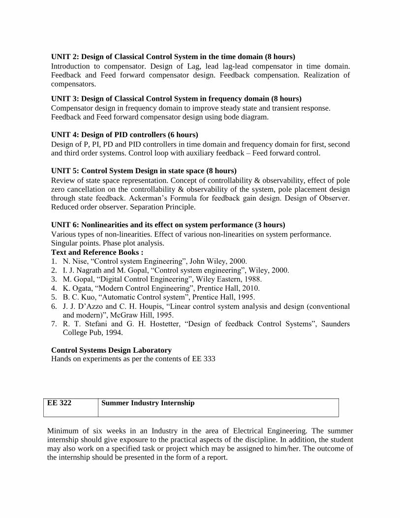
UNIT 2: Design of Classical Control System in the time domain (8 hours) Introduction to compensator. Design of Lag, lead lag-lead compensator in time domain. Feedback and Feed forward compensator design. Feedback compensation. Realization of compensators.
UNIT 3: Design of Classical Control System in frequency domain (8 hours) Compensator design in frequency domain to improve steady state and transient response. Feedback and Feed forward compensator design using bode diagram.
UNIT 4: Design of PID controllers (6 hours) Design of P, PI, PD and PID controllers in time domain and frequency domain for first, second and third order systems. Control loop with auxiliary feedback – Feed forward control.
UNIT 5: Control System Design in state space (8 hours) Review of state space representation. Concept of controllability & observability, effect of pole zero cancellation on the controllability & observability of the system, pole placement design through state feedback. Ackerman’s Formula for feedback gain design. Design of Observer. Reduced order observer. Separation Principle.
UNIT 6: Nonlinearities and its effect on system performance (3 hours) Various types of non-linearities. Effect of various non-linearities on system performance. Singular points. Phase plot analysis. Text and Reference Books :
1. N. Nise, “Control system Engineering”, John Wiley, 2000. 2. I. J. Nagrath and M. Gopal, “Control system engineering”, Wiley, 2000. 3. M. Gopal, “Digital Control Engineering”, Wiley Eastern, 1988. 4. K. Ogata, “Modern Control Engineering”, Prentice Hall, 2010. 5. B. C. Kuo, “Automatic Control system”, Prentice Hall, 1995. 6. J. J. D’Azzo and C. H. Houpis, “Linear control system analysis and design (conventional
and modern)”, McGraw Hill, 1995. 7. R. T. Stefani and G. H. Hostetter, “Design of feedback Control Systems”, Saunders
College Pub, 1994.
Control Systems Design Laboratory Hands on experiments as per the contents of EE 333
EE 322 Summer Industry Internship
Minimum of six weeks in an Industry in the area of Electrical Engineering. The summer internship should give exposure to the practical aspects of the discipline. In addition, the student may also work on a specified task or project which may be assigned to him/her. The outcome of the internship should be presented in the form of a report.
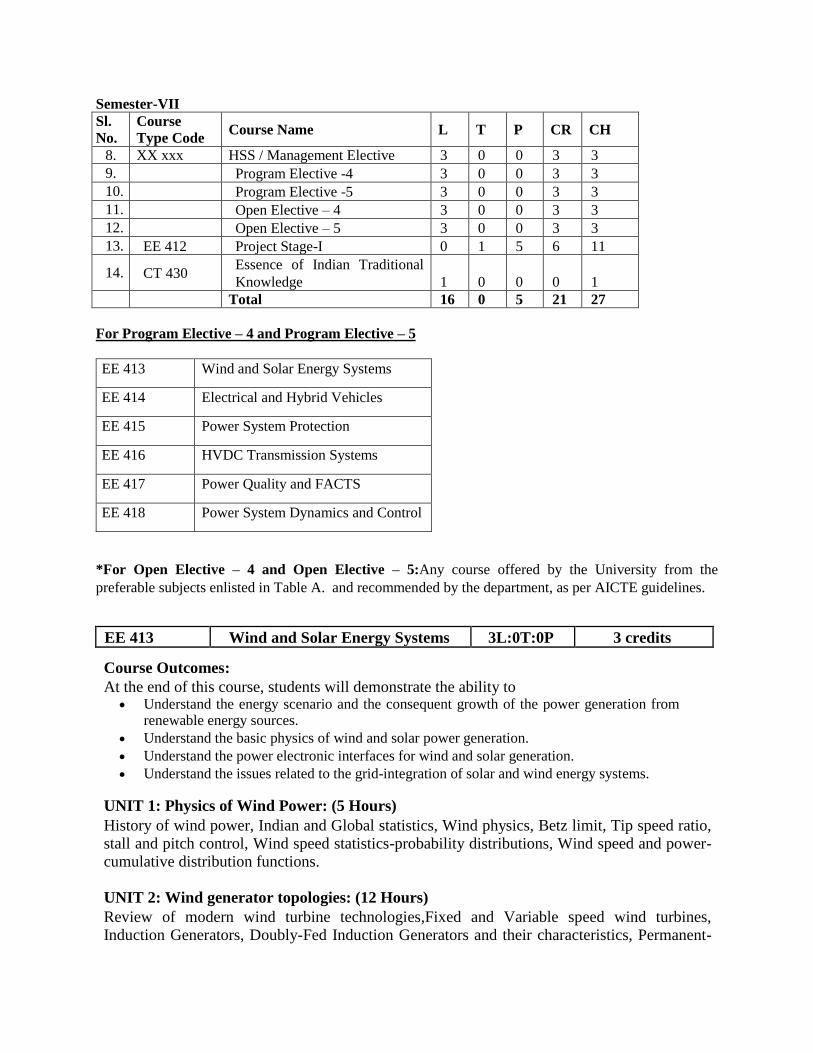
Semester-VII Sl.
No.
Course
Type Code Course Name L T P CR CH
8. XX xxx HSS / Management Elective 3 0 0 3 3
9. Program Elective -4 3 0 0 3 3
10. Program Elective -5 3 0 0 3 3
11. Open Elective – 4 3 0 0 3 3
12. Open Elective – 5 3 0 0 3 3
13. EE 412 Project Stage-I 0 1 5 6 11
14. CT 430 Essence of Indian Traditional
Knowledge 1 0 0 0 1
Total 16 0 5 21 27
For Program Elective – 4 and Program Elective – 5
EE 413 Wind and Solar Energy Systems
EE 414 Electrical and Hybrid Vehicles
EE 415 Power System Protection
EE 416 HVDC Transmission Systems
EE 417 Power Quality and FACTS
EE 418 Power System Dynamics and Control
*For Open Elective – 4 and Open Elective – 5:Any course offered by the University from the
preferable subjects enlisted in Table A. and recommended by the department, as per AICTE guidelines.
EE 413 Wind and Solar Energy Systems 3L:0T:0P 3 credits
Course Outcomes: At the end of this course, students will demonstrate the ability to
Understand the energy scenario and the consequent growth of the power generation from renewable energy sources.
Understand the basic physics of wind and solar power generation. Understand the power electronic interfaces for wind and solar generation. Understand the issues related to the grid-integration of solar and wind energy systems.
UNIT 1: Physics of Wind Power: (5 Hours) History of wind power, Indian and Global statistics, Wind physics, Betz limit, Tip speed ratio, stall and pitch control, Wind speed statistics-probability distributions, Wind speed and power-cumulative distribution functions.
UNIT 2: Wind generator topologies: (12 Hours) Review of modern wind turbine technologies,Fixed and Variable speed wind turbines, Induction Generators, Doubly-Fed Induction Generators and their characteristics, Permanent-
Magnet Synchronous Generators, Power electronics converters. Generator-Converter configurations, Converter Control.
UNIT 3: The Solar Resource: (3 Hours) Introduction, solar radiation spectra, solar geometry, Earth Sun angles, observer Sun angles, solar day length, Estimation of solar energy availability.
UNIT 4: Solar photovoltaic: (8 Hours) Technologies-Amorphous, monocrystalline, polycrystalline; V-I characteristics of a PV cell, PV module, array, Power Electronic Converters for Solar Systems, Maximum Power Point Tracking (MPPT) algorithms.Converter Control.
UNIT 5: Network Integration Issues: (8 Hours) Overview of grid code technical requirements. Fault ride-through for wind farms - real and reactive power regulation, voltage and frequency operating limits, solar PV and wind farm behavior during grid disturbances. Power quality issues. Power system interconnection experiences in the world. Hybrid and isolated operations of solar PV and wind systems.
UNIT 6: Solar thermal power generation: (3 Hours) Technologies, Parabolic trough, central receivers, parabolic dish, Fresnel, solar pond,
elementary analysis
Text / References: 1. T. Ackermann, “Wind Power in Power Systems”, John Wiley and Sons Ltd., 2005.
2. G. M. Masters, “Renewable and Efficient Electric Power Systems”, John Wiley and Sons, 2004. 3. S. P. Sukhatme, “Solar Energy: Principles of Thermal Collection and Storage”, McGraw Hill, 1984. 4. H. Siegfried and R. Waddington, “Grid integration of wind energy conversion systems” John Wiley
and Sons Ltd., 2006. 5. G. N. Tiwari and M. K. Ghosal, “Renewable Energy Applications”, Narosa Publications, 2004. 6. J. A. Duffie and W. A. Beckman, “Solar Engineering of Thermal Processes”, John Wiley & Sons,
1991
EE 414 Electrical and Hybrid Vehicles 3L:0T:0P 3 credits
Course Outcomes: At the end of this course, students will demonstrate the ability to
Understand the models to describe hybrid vehicles and their performance.
Understand the different possible ways of energy storage.
Understand the different strategies related to energy storage systems.
UNIT 1: Introduction (10 hours) Conventional Vehicles: Basics of vehicle performance, vehicle power source characterization, transmission characteristics, mathematical models to describe vehicle performance.

Introduction to Hybrid Electric Vehicles: History of hybrid and electric vehicles, social and environmental importance of hybrid and electric vehicles, impact of modern drive-trains on energy supplies. Hybrid Electric Drive-trains: Basic concept of hybrid traction, introduction to various hybrid drive-train topologies, power flow control in hybrid drive-train topologies, fuel efficiency analysis.
UNIT 3: Electric Trains (10 hours) Electric Drive-trains: Basic concept of electric traction, introduction to various electric drive-train topologies, power flow control in electric drive-train topologies, fuel efficiency analysis. Electric Propulsion unit: Introduction to electric components used in hybrid and electric vehicles, Configuration and control of DC Motor drives, Configuration and control of Induction Motor drives, configuration and control of Permanent Magnet Motor drives, Configuration and control of Switch Reluctance Motor drives, drive system efficiency.
UNIT 4: Energy Storage (10 hours) Energy Storage: Introduction to Energy Storage Requirements in Hybrid and Electric Vehicles, Battery based energy storage and its analysis, Fuel Cell based energy storage and its analysis, Super Capacitor based energy storage and its analysis, Flywheel based energy storage and its analysis, Hybridization of different energy storage devices. Sizing the drive system: Matching the electric machine and the internal combustion engine (ICE), Sizing the propulsion motor, sizing the power electronics, selecting the energy storage technology, Communications, supporting subsystems
UNIT 5: Energy Management Strategies (9 hours) Energy Management Strategies: Introduction to energy management strategies used in hybrid and electric vehicles, classification of different energy management strategies, comparison of different energy management strategies, implementation issues of energy management strategies. Case Studies: Design of a Hybrid Electric Vehicle (HEV), Design of a Battery Electric Vehicle (BEV).
Text / References: 1. C. Mi, M. A. Masrur and D. W. Gao, “Hybrid Electric Vehicles: Principles and Applications
with Practical Perspectives”, John Wiley & Sons, 2011. 2. S. Onori, L. Serrao and G. Rizzoni, “Hybrid Electric Vehicles: Energy Management
Strategies”, Springer, 2015. 3. M. Ehsani, Y. Gao, S. E. Gay and A. Emadi, “Modern Electric, Hybrid Electric, and Fuel
Cell Vehicles: Fundamentals, Theory, and Design”, CRC Press, 2004. 4. T. Denton, “Electric and Hybrid Vehicles”, Routledge, 2016
EE 415 Power System Protection 3L:0T:0P 3 credits
Course Outcomes: At the end of this course, students will demonstrate the ability to Understand the different components of a protection system. Evaluate fault current due to different types of fault in a network.
Understand the protection schemes for different power system components.
Understand the basic principles of digital protection. Understand system protection schemes, and the use of wide-area measurements.
UNIT 1: Introduction and Components of a Protection System (4 hours) Principles of
Power System Protection, Relays, Instrument transformers, Circuit Breakers
UNIT 2: Faults and Over-Current Protection (8 hours) Review of Fault Analysis, Sequence Networks. Introduction to Overcurrent Protection and overcurrent relay co-ordination.
UNIT 3: Equipment Protection Schemes(8 hours) Directional, Distance, Differential protection. Transformer and Generator protection. Bus bar Protection, Bus Bar arrangement schemes.
UNIT 4: Digital Protection (8 hours) Computer-aided protection, Fourier analysis and estimation of Phasors from DFT. Sampling, aliasing issues.
UNIT 5: Modeling and Simulation of Protection Schemes (8 hours) CT/PT modeling and standards, Simulation of transients using Electro-Magnetic Transients (EMT) programs. Relay Testing.
UNIT 6: System Protection (4 hours) Effect of Power Swings on Distance Relaying. System Protection Schemes. Under-frequency, under-voltage and df/dt relays, Out-of-step protection, Synchro-phasors, Phasor Measurement Units and Wide-Area Measurement Systems (WAMS). Application of WAMS for improving protection systems.
Text/References 1. J. L. Blackburn, “Protective Relaying: Principles and Applications”, Marcel Dekker, New
York, 1987. 2. Y. G.Paithankar and S. R. Bhide, “Fundamentals of power system protection”, Prentice
Hall, India, 2010. 3. A. G. Phadke and J. S. Thorp, “Computer Relaying for Power Systems”, John Wiley &
Sons, 1988. 4. A. G. Phadke and J. S. Thorp, “Synchronized Phasor Measurements and their
Applications”, Springer, 2008. 5. D. Reimert, “Protective Relaying for Power Generation Systems”, Taylor and Francis,
2006.
EE 416 HVdc Transmission Systems 3L:0T:0P 3 credits
Course Outcomes: At the end of this course, students will demonstrate the ability to
Understand the advantages of dc transmission over ac transmission. Understand the operation of Line Commutated Converters and Voltage Source
Converters. Understand the control strategies used in HVdc transmission system.

Understand the improvement of power system stability using an HVdc system.
UNIT 1:dc Transmission Technology (4 hours) Comparison of AC and dc Transmission (Economics, Technical Performance and Reliability). Application of DC Transmission. Types of HVdc Systems. Components of a HVdc system. Line Commutated Converter and Voltage Source Converter based systems.
UNIT 2: Analysis of Line Commutated and Voltage Source Converters (10 hours) Line Commutated Converters (LCCs): Six pulse converter, Analysis neglecting commutation overlap, harmonics, Twelve Pulse Converters. Inverter Operation. Effect of Commutation
Overlap. Expressions for average dc voltage, AC current and reactive power absorbed by the converters. Effect of Commutation Failure, Misfire and Current Extinction in LCC links.
Voltage Source Converters (VSCs): Two and Three-level VSCs. PWM schemes: Selective Harmonic Elimination, Sinusoidal Pulse Width Modulation. Analysis of a six pulse converter.
Equations in the rotating frame. Real and Reactive power control using a VSC.
UNIT 3:Control of HVdc Converters: (10 hours) Principles of Link Control in a LCCHVdc system. Control Hierarchy, Firing Angle Controls – Phase-Locked Loop, Current and Extinction Angle Control, Starting and Stopping of a Link.
Higher level Controllers Power control, Frequency Control, Stability Controllers. Reactive Power Control. Principles of Link Control in a VSC HVdc system: Power flow and dc Voltage
Control. Reactive Power Control/AC voltage regulation.
UNIT 3:Components of HVdc systems: (8 hours) Smoothing Reactors, Reactive Power Sources and Filters in LCC HVdc systems DC line:
Corona Effects. Insulators, Transient Over-voltages. dc line faults in LCC systems. dc line faults in VSC systems. dc breakers. Monopolar Operation. Ground Electrodes.
UNIT 4:Stability Enhancement using HVdc Control (4 hours) Basic Concepts: Power System Angular, Voltage and Frequency Stability. Power Modulation: basic principles – synchronous and asynchronous links. Voltage Stability Problem in AC/dc systems.
UNIT 5:MTdc Links (4 hours) Multi-Terminal and Multi-Infeed Systems. Series and Parallel MTdc systems using LCCs. MTdc systems using VSCs. Modern Trends in HVdcTechnology. Introduction to Modular Multi-level Converters.
Text/References: 1. K. R. Padiyar, “HVDC Power Transmission Systems”, New Age International Publishers, 2011. 2. J. Arrillaga, “High Voltage Direct Current Transmission”, Peter Peregrinus Ltd., 1983. 3. E. W. Kimbark, “Direct Current Transmission”, Vol.1, Wiley-Interscience, 1971
EE 417 Power Quality and FACTS 3L:0T:0P 3 credits
Course Outcomes: At the end of this course, students will demonstrate the ability to
Understand the characteristics of ac transmission and the effect of shunt and series reactive compensation. Understand the working principles of FACTS devices and their operating characteristics.
Understand the basic concepts of power quality. Understand the working principles of devices to improve power quality.
UNIT 1: Transmission Lines and Series/Shunt Reactive Power Compensation (4 hours) Basics of AC Transmission. Analysis of uncompensated AC transmission lines. Passive Reactive Power Compensation. Shunt and series compensation at the mid-point of an AC line. Comparison of Series and Shunt Compensation.
UNIT 2: Thyristor-based Flexible AC Transmission Controllers (FACTS) (6 hours) Description and Characteristics of Thyristor-based FACTS devices: Static VAR Compensator (SVC), Thyristor Controlled Series Capacitor (TCSC), Thyristor Controlled Braking Resistor and Single Pole Single Throw (SPST) Switch. Configurations/Modes of Operation, Harmonics and control of SVC and TCSC. Fault Current Limiter.
UNIT 3: Voltage Source Converter based (FACTS) controllers (8 hours) Voltage Source Converters (VSC): Six Pulse VSC, Multi-pulse and Multi-level Converters,
Pulse-Width Modulation for VSCs. Selective Harmonic Elimination, Sinusoidal PWM and
Space Vector Modulation. STATCOM: Principle of Operation, Reactive Power Control: Type
I and Type II controllers, Static Synchronous Series Compensator (SSSC) and Unified Power
Flow Controller (UPFC): Principle of Operation and Control. Working principle of Interphase
Power Flow Controller. Other Devices: GTO Controlled Series Compensator. Fault Current
Limiter.
UNIT 4: Application of FACTS (4 hours) Application of FACTS devices for power-flow control and stability improvement. Simulation example of power swing damping in a single-machine infinite bus system using a TCSC. Simulation example of voltage regulation of transmission mid-point voltage using
aSTATCOM.
UNIT 5: Power Quality Problems in Distribution Systems (4 hours) Power Quality problems in distribution systems: Transient and Steady state variations in
voltage and frequency. Unbalance, Sags, Swells, Interruptions, Wave-form Distortions: harmonics, noise, notching, dc-offsets, fluctuations. Flicker and its measurement. Tolerance of
Equipment: CBEMA curve.
UNIT 6: DSTATCOM (8 hours)

Reactive Power Compensation, Harmonics and Unbalance mitigation in Distribution Systems using DSTATCOM and Shunt Active Filters. Synchronous Reference Frame Extraction of Reference Currents. Current Control Techniques in for DSTATCOM. UNIT 6: Dynamic Voltage Restorer and Unified Power Quality Conditioner (6 hours)
Voltage Sag/Swell mitigation: Dynamic Voltage Restorer – Working Principle and Control Strategies. Series Active Filtering. Unified Power Quality Conditioner (UPQC): Working Principle. Capabilities and Control Strategies.
Text/References 1. N. G. Hingorani and L. Gyugyi, “Understanding FACTS: Concepts and Technology of FACTS Systems”, Wiley-IEEE Press, 1999. 2. K. R. Padiyar, “FACTS Controllers in Power Transmission and Distribution”, New Age International (P) Ltd. 2007. 3. T. J. E. Miller, “Reactive Power Control in Electric Systems”, John Wiley and Sons, New York, 1983. 4. R. C. Dugan, “Electrical Power Systems Quality”, McGraw Hill Education, 2012.
5. G. T. Heydt, “Electric Power Quality”, Stars in a Circle Publications, 1991
EE 418 Power System Dynamics andControl 3L:0T:0P 3 credits
Course Outcomes: At the end of this course, students will demonstrate the ability to
Understand the problem of power system stability and its impact on the system.
Analyse linear dynamical systems and use of numerical integration methods. Model different power system components for the study of stability.
Understand the methods to improve stability.
UNIT 1: Introduction to Power System Operations (3 hours) Introduction to power system stability. Power System Operations and Control. Stability problems in Power System. Impact on Power System Operations and control.
UNIT 2 : Analysis of Linear Dynamical System and Numerical Methods (5 hours)
Analysis of dynamical System, Concept of Equilibrium, Small and Large Disturbance
Stability. Modal Analysis of Linear System. Analysisusing Numerical Integration Techniques.
Issues in Modeling: Slow and Fast Transients, Stiff System.
UNIT3 : Modeling of Synchronous Machines and Associated Controllers (12 hours) Modeling of synchronous machine: Physical Characteristics. Rotor position dependent model.
D-Q Transformation. Model with Standard Parameters. Steady State Analysis of Synchronous
Machine. Short Circuit Transient Analysis of a Synchronous Machine. Synchronization of Synchronous Machine to an Infinite Bus. Modeling of Excitation and Prime Mover Systems.
Physical Characteristics and Models. Excitation System Control. Automatic Voltage Regulator. Prime Mover Control Systems. Speed Governors.
UNIT4 : Modeling of other Power System Components (10 hours)
Modeling of Transmission Lines and Loads. Transmission Line Physical Characteristics. Transmission Line Modeling. Load Models - induction machine model. Frequency and Voltage Dependence of Loads. Other Subsystems – HVDC and FACTS controllers, Wind Energy Systems.
UNIT5 : Stability Analysis (11 hours) Angular stability analysis in Single Machine Infinite Bus System. Angular Stability in multi-machine systems – Intra-plant, Local and Inter-area modes. Frequency Stability: Centre of
Inertia Motion. Load Sharing: Governordroop. Single Machine Load Bus System: Voltage Stability. Introduction to Torsional Oscillations and the SSR phenomenon. Stability Analysis
Tools:Transient Stability Programs, Small Signal Analysis Programs.
UNIT6 : Enhancing System Stability (4 hours) Planning Measures. Stabilizing Controllers (Power System Stabilizers). Operational Measures-
Preventive Control. Emergency Control
Text/Reference Books
1. K.R. Padiyar, “Power System Dynamics, Stability and Control”, B. S. Publications, 2002.
2. P. Kundur, “Power System Stability and Control”, McGraw Hill, 1995. 3. P. Sauer and M. A. Pai, “Power System Dynamics and Stability”, Prentice Hall, 1997
EE 412 Project Work –I 0L:1T:5P 6 credits
The object of Project Work I is to enable the student to take up investigative study in the broad field of Electronics & Communication Engineering, either fully theoretical/practical or
involving both theoretical and practical work to be assigned by the Department on an individual basis or two/three students in a group, under the guidance of a Supervisor. This is
expected to provide a good initiation for the student(s) in R&D work. The assignment to normally include:
1. Survey and study of published literature on the assigned topic; 2. Working out a preliminary Approach to the Problem relating to the assigned topic; 3. Conducting preliminary
Analysis/Modelling/Simulation/Experiment/Design/Feasibility; 4. Preparing a Written Report on the Study conducted for presentation to the Department; 5. Final Seminar, as oral Presentation before a departmental committee.
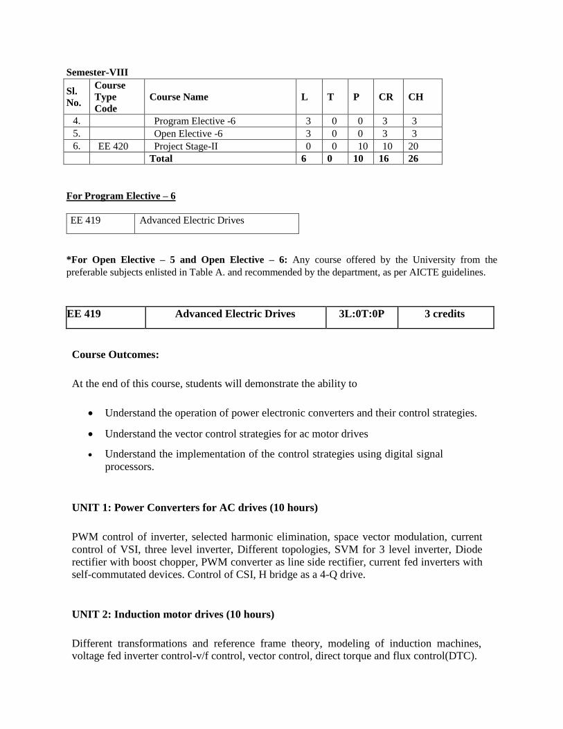
Semester-VIII
Sl.
No.
Course
Type
Code
Course Name L T P CR CH
4. Program Elective -6 3 0 0 3 3
5. Open Elective -6 3 0 0 3 3
6. EE 420 Project Stage-II 0 0 10 10 20
Total 6 0 10 16 26
For Program Elective – 6
EE 419 Advanced Electric Drives
*For Open Elective – 5 and Open Elective – 6: Any course offered by the University from the
preferable subjects enlisted in Table A. and recommended by the department, as per AICTE guidelines.
EE 419 Advanced Electric Drives 3L:0T:0P 3 credits
Course Outcomes:
At the end of this course, students will demonstrate the ability to
Understand the operation of power electronic converters and their control strategies.
Understand the vector control strategies for ac motor drives
Understand the implementation of the control strategies using digital signal
processors.
UNIT 1: Power Converters for AC drives (10 hours)
PWM control of inverter, selected harmonic elimination, space vector modulation, current
control of VSI, three level inverter, Different topologies, SVM for 3 level inverter, Diode
rectifier with boost chopper, PWM converter as line side rectifier, current fed inverters with self-commutated devices. Control of CSI, H bridge as a 4-Q drive.
UNIT 2: Induction motor drives (10 hours)
Different transformations and reference frame theory, modeling of induction machines, voltage fed inverter control-v/f control, vector control, direct torque and flux control(DTC).
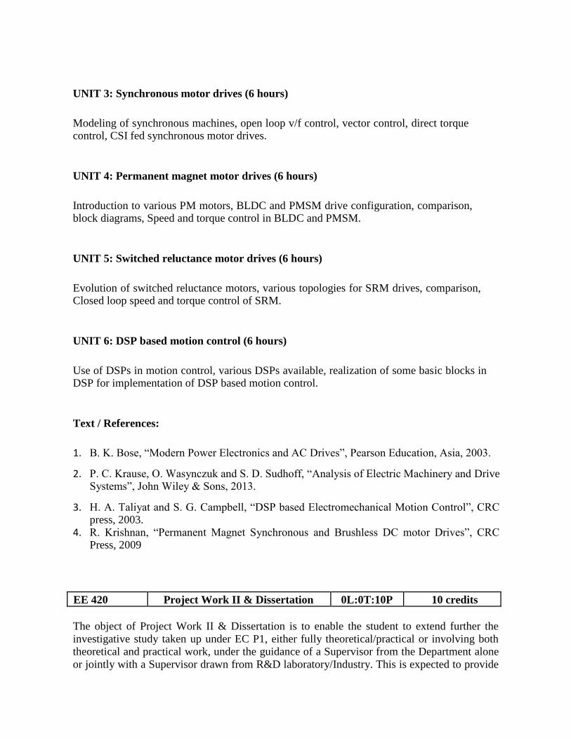
UNIT 3: Synchronous motor drives (6 hours)
Modeling of synchronous machines, open loop v/f control, vector control, direct torque control, CSI fed synchronous motor drives.
UNIT 4: Permanent magnet motor drives (6 hours)
Introduction to various PM motors, BLDC and PMSM drive configuration, comparison, block diagrams, Speed and torque control in BLDC and PMSM.
UNIT 5: Switched reluctance motor drives (6 hours)
Evolution of switched reluctance motors, various topologies for SRM drives, comparison, Closed loop speed and torque control of SRM.
UNIT 6: DSP based motion control (6 hours)
Use of DSPs in motion control, various DSPs available, realization of some basic blocks in DSP for implementation of DSP based motion control.
Text / References:
1. B. K. Bose, “Modern Power Electronics and AC Drives”, Pearson Education, Asia, 2003.
2. P. C. Krause, O. Wasynczuk and S. D. Sudhoff, “Analysis of Electric Machinery and Drive Systems”, John Wiley & Sons, 2013.
3. H. A. Taliyat and S. G. Campbell, “DSP based Electromechanical Motion Control”, CRC press, 2003.
4. R. Krishnan, “Permanent Magnet Synchronous and Brushless DC motor Drives”, CRC Press, 2009
EE 420 Project Work II & Dissertation 0L:0T:10P 10 credits
The object of Project Work II & Dissertation is to enable the student to extend further the
investigative study taken up under EC P1, either fully theoretical/practical or involving both theoretical and practical work, under the guidance of a Supervisor from the Department alone
or jointly with a Supervisor drawn from R&D laboratory/Industry. This is expected to provide
a good training for the student(s) in R&D work and technical leadership. The assignment to normally include:
1. In depth study of the topic assigned in the light of the Report prepared under EEP1; 2. Review and finalization of the Approach to the Problem relating to the assigned topic; 3. Preparing an Action Plan for conducting the investigation, including team work; 4. Detailed Analysis/Modelling/Simulation/Design/Problem Solving/Experiment as
needed; 5. Final development of product/process, testing, results, conclusions and future
directions; 6. Preparing a paper for Conference presentation/Publication in Journals, if possible; 7. Preparing a Dissertation in the standard format for being evaluated by the Department. 8. Final Seminar Presentation before a Departmental Committee


![Compiler Construction - Lecture : [1ex] Summer Semester](https://img.dokumen.tips/doc/110x75/61d77c7ad49dc75e3c0f7396/compiler-construction-lecture-1ex-summer-semester-.jpg)


