Embed Size (px)
Citation preview

PROPOSED MAJOR HAZARD INSTALLATION RISK ASSESSMENT OTGC TERMINALS MAYDON WHARF DURBAN

ISHECON CHEMICAL PROCESS SAFETY ENGINEERS
J2885R OTGC MHI RA Maydon MolDegHFBitRev1 Page 1
REPORT:
FINAL
PROPOSED MAJOR HAZARD INSTALLATION RISK ASSESSMENT
STORAGE OF MOLASSES, DIETHYL GLYCOL, HEAVY FUEL OILS AND BITUMEN
OTGC TERMINALS
MAYDON WHARF
DURBAN
ASSIGNMENT NO: J2885R Rev1
ASSESSED BY:
TECHNICAL SIGNATORY:
Telephone:
e-mail :
D J E Rademeyer
Daniël J E Rademeyer
011 201 4786
CLIENT: Organisation:
Representative:
Address:
Installation representative:
Telephone no.
OTGC
Alyssa Singh – HSSE Manager
55 Johnstone Road
Maydon Wharf
Durban, 4000
Alyssa Singh – HSSE Manager
27 31 205 6200
ASSESSMENT DATE:
REPORT ISSUED
12 February 2021
30 April 2021
ISHECON, H6 Pinelands Office Park, Maxwell Drive, Modderfontein, Box 320 Modderfontein 1645
Registration No.: CK 99/29022/23

ISHECON CHEMICAL PROCESS SAFETY ENGINEERS
J2885R OTGC MHI RA Maydon MolDegHFBitRev1 Page 2
REPORT ADMINSTRATIVE RECORD
Assessment Rev. No. Date Description
Original 0 12 February 2021 Site visit and inspection
Original 0 29 April 2021 Issue draft report to client for comments
Original 1 30 April 2021 Incorporated comments and issued final report
VALIDITY OF THE RISK ASSESSMENT CONTRIBUTORS ACKNOWLEGEMENTS The validity, results and conclusions of this assessment are based on the expertise, skills and information, provided by the following contributing team members, who are responsible for the design, operation and maintenance of the plant and equipment, and who also assisted with the site visit:
NAME ORGANISATION DISCIPLINE EXPERTISE
Alyssa Singh OTGC HSSE Manager
Reagan Naidoo OTGC Shift leader
DISTRIBUTION Copies of the report
NAME ORGANISATION
D J E RADEMEYER (Original) ISHECON
Alyssa Naidoo OTGC
NOTIFICATIONS By client
AUTHORITY, NAME OR DESIGNATION ADDRESS Local Authority – Fire Services Chief Fire Officer Sandile Dladla
Emergency Planning Officer and Convenor of the MHI Task Force, eThekwini Municipality – Fire Dept., Fire Safety Section, 1 Blaze Way, Amanzimtoti, Durban Tel: 031 903 9000
Department of Labour Provincial Office Chief Director – Thembi Nene -Shezi
P O Box 940, Durban, 4000, Tel: (031) 366 2019

ISHECON CHEMICAL PROCESS SAFETY ENGINEERS
J2885R OTGC MHI RA Maydon MolDegHFBitRev1 Page 3
AUTHORITY, NAME OR DESIGNATION ADDRESS
National Department of Labour Chief Inspector OHS, Major Hazard Installations c/o Ms Rachel Aphane Deputy Director for Major Hazard Installations
Department of Labour – Laboria House 215 Schoeman Street Pretoria 0001 Tel: (012) 309 4766 (Roy Chauke, Technical Assistant: MHI)
DISCLAIMER Note that although every effort has been made to obtain the correct information and to carry out an appropriate, independent, impartial and competent study, ISHECON cannot be held liable for any incident which directly, or indirectly, relates to the work in this document and which may have an effect on the client or on any other third party. CONFIDENTIALITY All information, results and findings will be kept confidential and will not be distributed to other parties except with the expressed permission of the client. The exception to this confidentiality is the requirement from the Department of Labour for Approved Inspection Authorities to inform them every month of the Risk Assessments conducted under accreditation. As Approved Inspection Authorities for the Department of Labour, ISHECON is also under legal obligation to the Department of Labour to report any obvious violations of the OHS Act. PROOF READING: Report spelling and grammar verified by K J Henning April 2021

ISHECON CHEMICAL PROCESS SAFETY ENGINEERS
J2885R OTGC MHI RA Maydon MolDegHFBitRev1 Page 4
SUMMARY Oiltanking Grindrod Calulo (Pty) Ltd (OTGC), at present, operates a bulk storage facility at the Maydon Wharf site inside the Port of Durban. Molasses, mono-and di- ethylene glycols are offloaded from ships at berths 9 and 10 at Maydon Wharf and transferred along pipelines into storage tanks. Products are then loaded into road tankers, via a road loading gantry for distribution to customers. There is also a truck and vehicle parking building on the site. It is intended to, in addition, import heavy fuel oil and bitumen by ship, offloading storage and filling of road tankers for distribution inland. Since glycols, heavy fuel oil and bitumen are combustible materials, a fire incident may affect people in the vicinity. Thus a major hazard risk assessment was carried out, as per the Major Hazard Installation regulations under the Occupational Health and Safety Act. The quantitative risk assessment was done according to the South African standard, which includes identification of the major hazards, a cause analysis and a consequence analysis. If these indicated potential to seriously affect members of the public outside, the site would be classified as a Major Hazard Installation. Risks were estimated in terms of the individual risks1 and societal risks2 and assessed against acceptability criteria3. Suitability of emergency measures and organisational aspects were reviewed. Finally, measures were proposed to reduce or eliminate the risk. Molasses handling at present does not have any significant impact on safety, health or the environment. Heavy fuel oils, mono and di - ethylene glycols and bitumen can lead to thermal burn injuries on persons, in the event of a fire. Spillages of molasses into the environment will have little impact apart from inconveniences, e.g. sticky and slippery. The glycol, heavy fuel oil and bitumen spillages can have an impact on aquatic life in the harbour water if spilt. Toxic effects were found to be insignificant. As a worst case scenario, should a heavy bitumen tank burst, followed by ignition, serious flash fire effects would be felt as far as 39 m away. Overall the individual risk of being exposed to fatal hazards at the centre of the site where employees are present was found to be a 3 * 10-6 chance of a fatality per person per year. At the site boundary the maximum risk would be a 2 * 10-7 chance of a fatality per person per year.
These low risks are due to glycols, heavy fuel oil and bitumen having such high flash points that it is almost impossible to be ignited under normal process operating conditions.
The OTGC terminal site does not qualify as a Major Hazard Installation as its operation does not have the potential to seriously impact on public persons outside its boundary and consequently the site is not classified as a major hazard installation. Further, justification for not classifying the site as a Major Hazard installation is the fact that the risks are extremely low, approaching zero. Risks were presented only because the probability of ignition was increased to 10 -50% to allow for the possibility of arson, which is nevertheless considered very unlikely.
1 The frequency at which an individual may be expected to sustain a given level of harm from the realisation of specified hazards. 2 This is the relationship between the frequency and the number of people suffering from a specified level of harm in a given population from the realisation of specified hazards. 3 A standard or a norm.

ISHECON CHEMICAL PROCESS SAFETY ENGINEERS
J2885R OTGC MHI RA Maydon MolDegHFBitRev1 Page 5
There are no other installations in the area close enough to be significantly affected by the OTGC site. In terms of domino effects, a possible fire on a tank could heat up an adjacent tank, which could eventually become flammable, escalating the hazard.
Starting a fire inside the bunds would be extremely difficult due to the high flash and fire points of the oils. Applying a blow torch may ignite some of the oil on the surface, but as soon as the torch is removed, the flame will go out, since the bulk of the liquid will still be far below the flash point.
Principal recommendation were to keep register of all near miss incidents related to the operation of the installation, institute process safety management, update the on–site emergency plant for handling heavy fuel oil and bitumen and to implement fire water protection measures to minimise fire radiation heat effects on the nearby wood chip storage building. Signed: Daniël J E Rademeyer – Risk Assessment Technical Signatory ISHECON - Approved Inspection Authority as per Appendix 6. Date: 30 April 2021
ISHECON CHEMICAL PROCESS SAFETY ENGINEERS
____________________________________________________________________________________
J2885R OTGC MHI RA Maydon MolDegHFBitRev1 Page 6 of 97
TABLE OF CONTENTS
1. INTRODUCTION AND METHODOLOGY ________________________________________________ 10
1.1 MAJOR HAZARD INSTALLATION REGULATION SCOPE APPLICATION _____________________ 10
1.2 CRITERIA FOR CLASSIFICATION AS A MAJOR HAZARD INSTALLATION ____________________ 10
1.3 RISK ASSESSMENT METHODOLOGY ______________________________________________ 10
2. DESCRIPTIONS __________________________________________________________________ 10
2.1 ORGANISATION, SITE LOCATION AND SURROUNDING AREAS _________________________ 10 2.1.1 Organisation ______________________________________________________________ 10 2.1.2 Physical address ___________________________________________________________ 10 2.1.3 Location _________________________________________________________________ 11 2.1.4 Topography, ecology and meteorology _________________________________________ 12
2.2 PLANT PROCESS AND OPERATIONS ______________________________________________ 13 2.2.1 Origin, manufacture, installation and erection date _______________________________ 13 2.2.2 Plant ____________________________________________________________________ 13 2.2.3 Process and operations _____________________________________________________ 15 2.2.4 Organisational management _________________________________________________ 15 2.2.5 Unique or abnormal conditions _______________________________________________ 15 2.2.6 Inventories of materials on site _______________________________________________ 15
3. RISK ASSESSMENT ________________________________________________________________ 16
3.1 IDENTIFICATION OF HAZARDS __________________________________________________ 16 3.1.1 Hazardous Materials in the Process ____________________________________________ 16 3.1.2 Environmental Hazards _____________________________________________________ 17 3.1.3 Hazardous Material Interactions ______________________________________________ 17
3.2 PAST INCIDENTS _____________________________________________________________ 17
4. HAZARD ANALYSIS _______________________________________________________________ 18
4.1 SECTIONS ANALYSED _________________________________________________________ 18
4.2 SAFETY MEASURES ___________________________________________________________ 19
4.3 CONSEQUENCES _____________________________________________________________ 19
4.4 ANALYSIS __________________________________________________________________ 19
5. CONSEQUENCE ANALYSIS __________________________________________________________ 21
5.1 EFFECT DISTANCES ___________________________________________________________ 21 5.1.1 Hazard Effect Zones ________________________________________________________ 23
5.2 Qualification as a Major Hazard Installation _______________________________________ 25 5.2.1 Notification of Major Hazard Installation ________________________________________ 25 5.2.2 Reporting of Emergency Occurrences __________________________________________ 26 5.2.3 Effect on adjacent Major Hazard Installations ____________________________________ 26 5.2.4 Hazard escalation domino effects _____________________________________________ 26
6. LIKELIHOOD ANALYSIS ____________________________________________________________ 26
7. RISK RESULTS ___________________________________________________________________ 26 7.1.1 Risk Contours _____________________________________________________________ 26 7.1.2 Risk Profiles ______________________________________________________________ 27 7.1.3 Societal Risk ______________________________________________________________ 28

ISHECON CHEMICAL PROCESS SAFETY ENGINEERS
____________________________________________________________________________________
J2885R OTGC MHI RA Maydon MolDegHFBitRev1 Page 7 of 97
8. ENVIRONMENTAL ________________________________________________________________ 29
9. RISK JUDGEMENT ________________________________________________________________ 29
9.1 WORKFORCE INDIVIDUAL RISK __________________________________________________ 29
9.2 PUBLIC INDIVIDUAL RISK ______________________________________________________ 30
9.3 SOCIETAL RISKS ______________________________________________________________ 30
10. RISK TREATMENT ______________________________________________________________ 30
10.1 ORGANISATIONAL MEASURES __________________________________________________ 30
10.2 TECHNICAL MEASURES ________________________________________________________ 30
11. LAND USE PLANNING ___________________________________________________________ 31
12. EMERGENCY PLAN _____________________________________________________________ 32
12.1 INSTALLATION EMERGENCIES __________________________________________________ 32
12.2 ON-SITE EMERGENCIES _______________________________________________________ 32
12.3 OFF-SITE EMERGENCIES _______________________________________________________ 32
13. CONCLUSIONS AND DISCUSSION __________________________________________________ 32
13.1 INCIDENT IDENTIFICATION _____________________________________________________ 32
13.2 SEVERITY AND RISKS __________________________________________________________ 33 13.2.1 Severity ________________________________________________________________ 33 13.2.2 Individual risks __________________________________________________________ 33 13.2.3 Societal risks ____________________________________________________________ 33
13.3 RISK ACCEPTABILITY __________________________________________________________ 33
13.4 RISK REDUCTION_____________________________________________________________ 33
13.5 VALIDITY OF THE RISK ASSESSMENT _____________________________________________ 33
13.6 LAND USE __________________________________________________________________ 33
13.7 INTEGRITY ASSURANCE _______________________________________________________ 33
13.8 Operating Information ________________________________________________________ 34
13.9 Training ____________________________________________________________________ 34
13.10 Installation Security ________________________________________________________ 34
13.11 FIRE PROTECTION __________________________________________________________ 34
13.12 INSTRUMENTATION ________________________________________________________ 34
14. RECOMMENDATIONS ___________________________________________________________ 34
15. REFERENCES __________________________________________________________________ 35
15.1 Physical and flammable properties ______________________________________________ 38
15.2 Toxic Hazards _______________________________________________________________ 39
15.3 Material toxic data ___________________________________________________________ 40
15.4 Material incompatibility and interactions _________________________________________ 40 APPENDIXES APPENDIX 1 GENERAL RISK ASSESSMENT 35
ISHECON CHEMICAL PROCESS SAFETY ENGINEERS
____________________________________________________________________________________
J2885R OTGC MHI RA Maydon MolDegHFBitRev1 Page 8 of 97
APPENDIX 2 APPLICABLE REGULATIONS AND STANDARDS 36 APPENDIX 3 WIND WEATHER DATA 37 APPENDIX 4 MATERIAL DATA 38 APPENDIX 5 MODELLING DATA 41 APPENDIX 6 COMPETENCIES OF RISK ASSESSORS 46 APPENDIX 7 EMERGENCY PLAN 48

ISHECON CHEMICAL PROCESS SAFETY ENGINEERS
____________________________________________________________________________________
J2885R OTGC MHI RA Maydon MolDegHFBitRev1 Page 9 of 97
ACRYNOMS DEFINITIONS AND TERMINOLOGY AS USED IN THIS REPORT Frequently used terms in this report, and the interpretation or meaning attached to each of these terms can be found in the Major Hazard Installation regulations.
Acceptability
The evaluation of the risk in comparison to certain known levels of risk in other areas
Causes Occurrences that give rise to a hazardous incident, e.g. failure of a temperature indicator or pressure relief, etc.
Consequences The physical effects of hazardous incidents and the damage caused by these effects
EIA Environmental Impact Assessment
ERPG 1 Suffer only mild transient health effects and objectionable odour
ERPG 2 Not suffer irreversible or other serious health effects or symptoms that could impair abilities to take protective action
ERPG 3 Will not suffer life threatening health effects
fN Frequency of occurrence against number of people affected curve
Hazard A situation that has the potential to harm people, the environment or physical property
ha hectares
hr Hour
Incident An occurrence due to use of plant or machinery or from activities
Individual risk The frequency at which an individual may be expected to sustain a given level of harm from realisation of specified hazards
kW Kilo watt
kPa Kilo Pascals
MHI Major Hazard Installation
TLV Threshold Limit Value: The time weighted average concentration to which a person may be exposed for 8 hours per day, for a 40-hour week
STEL Short term exposure limit
IDLHV Immediately dangerous to life and health value
LNG Liquefied Natural Gas
LPG Liquid Petroleum Gas
m meters
m2 square meters
m3 Cubic meters
Odour threshold The concentration a person will smell the material
OHS Occupational Health and Safety
RA Risk Assessment
Risk Probability of a consequence affecting a particular person
s second
Severity
The seriousness of the consequences, e.g. death or injury or distress
Societal risk Frequency and the number of people suffering from a specified level of harm.
ISHECON CHEMICAL PROCESS SAFETY ENGINEERS
____________________________________________________________________________________
J2885R OTGC MHI RA Maydon MolDegHFBitRev1 Page 10 of 97
1. INTRODUCTION AND METHODOLOGY
Oiltanking Grindrod Calulo Terminals (Pty) Ltd (OTGC)’s current operations include the import via ship, the storage, handling and the distribution in road tankers of only molasses and glycols. It is intended to add the import, storage and distribution of heavy fuel oil and bitumen. The Port Authority requested that a Major Hazard Installation risk assessment be carried out on the site, which is the subject of this report. The management of OTGC discussed the case for a Major Hazard Installation risk assessment at the works’ Health and Safety Committee meeting where agreement was obtained.
1.1 MAJOR HAZARD INSTALLATION REGULATION SCOPE APPLICATION
This risk assessment is conducted to comply with the Major Hazard Installation Regulations under the South African Occupational Health and Safety Act. Refer to Appendix 1 for further details of the regulation requirements.
1.2 CRITERIA FOR CLASSIFICATION AS A MAJOR HAZARD INSTALLATION
Briefly, a Major Hazard Installation is an installation where a hazardous substance, which is listed in the General Machinery Regulations of the Occupational Health and Safety Act, is processed, handled or stored, and the content exceeds the quantity stipulated. Alternatively, if it is not listed, it may be an installation that has the potential to cause a major incident that might affect members of the public. Refer to Appendix 1 for details.
1.3 RISK ASSESSMENT METHODOLOGY
Risk is made up of two components:
The probability of a certain magnitude of a hazardous event occurring.
The severity of the consequences of the hazardous event. A risk assessment is, therefore, typically comprised of the following aspects:
Identification of the likely hazards expected to be associated with the operation of the installation;
Quantification of the hazards in terms of their likely frequency and magnitude;
Determination of the consequences of the hazards and their severity, should these occur;
Estimating the risk and comparing this with certain acceptability criteria. The regulation requires that a risk assessment should be carried out by a Department of Labour Approved Inspection Authority (AIA) to comply with the South African standard SANS 1461.2018 Edition 1. Refer to Appendix 6 for AIA approval certification for details of risk assessment standards, ISHECON procedures and Certification.
2. DESCRIPTIONS
2.1 ORGANISATION, SITE LOCATION AND SURROUNDING AREAS
2.1.1 Organisation
Oiltanking Grindrod Calulo Terminals (Pty) Ltd (OTGC) is a wholly owned subsidiary of an international company in France and the main focus is the storage and distribution of various chemical products.
2.1.2 Physical address
55 Johnstone Rd, Maydon Wharf, Durban, 4001 29 52’ 42” S, 32 00’ 17” E

ISHECON CHEMICAL PROCESS SAFETY ENGINEERS
____________________________________________________________________________________
J2885R OTGC MHI RA Maydon MolDegHFBitRev1 Page 11 of 97
2.1.3 Location
The location of the OTGC Terminal in relation to the rest of South Africa is shown in Figure 2-2 below.
Figure 2-1: The location of the OTGC Terminal in relation to the rest of South Africa OTGC operates from one location at Maydon Wharf, adjacent to the Cutler Complex, in Island View as shown in Figure 2-2 below. The Cutler Complex is located to the southwest of the Port of Durban.
Figure 2-2: Map showing the OTGC site at Maydon Wharf in the Port of Durban. OTGC handles molasses and glycols, which are offloaded from ships at berths 8 and 9 and transferred along a pipeline into the tanks. Products are then pumped out from the tanks and filled into road tankers
CAPE TOWNEAST LONDON
PORT ELIZABETH
MUSINA
GABORONE
Northern Cape
Eastern Cape
LESOTHO
SWAZILAND
Newcastle
NAMIBIA
Western Cape
POLOKWANE
DURBAN
JOHANNESBURG
PRETORIA
SASOLBURG
KIMBERLEY
BLOEMFONTEIN
NELSPRUIT
RICHARDS BAYNatalFree State
North West
Limpopo
Mpumalanga
OTGC
terminal
OTGCJohnstone Road
Fletcher Road

ISHECON CHEMICAL PROCESS SAFETY ENGINEERS
____________________________________________________________________________________
J2885R OTGC MHI RA Maydon MolDegHFBitRev1 Page 12 of 97
via two loading stations. See Figure 2-3 below for a layout of the site to, in addition, handle heavy fuel oil and bitumen.
Figure 2-3: Map showing the OTGC site and its key locations.
The OTGC Storage Terminal is located in a developed, transformed area that is designated for industrial activity. Principal areas of activity surrounding the storage site are… * Wood chip warehouse adjacent north across Fletcher Road. * Industries mainly related to freight handling and storage, shipping and engineering. * Maritime Training School, a Police Station, and railway tracks immediately adjacent to the site. * Other industrial companies approximately 1,2 km away (e.g. Unilever to the north, Gardner Smith to
the south and the Sugar Terminal north). * Harbour and bay area adjacent on the south side. * M4 Highway, 400 m northeast. * Glenwood residential area 1,4 km northwest. * Umbilo residential area 2,3 km west. * Railway staging area 2,3 km south and Clairwood residential area 4,3 km further south. * Parks and schools, e.g. Albert Park Bowling Green, Johnson Technical High School, etc. some distance
away. * The Indian Ocean and beach 4 km north east.
2.1.4 Topography, ecology and meteorology
The area around the OTGC site is essentially flat and surrounded by tall structures, e.g. large buildings, cranes, tanks some distance away and seawater in the bay. There are many railway lines crossing roads all around. No vegetation in the form of grass, bushes or trees is present. Meteorological conditions are typically coastal with high humidity and morning and evening sea winds from the north and northeast. Winter nights are cool with some temperature inversions. Generally days are clear, windy and sunny. Rainfall is in summer. The dominant wind directions are from the north-northeast (21,5 % of time) and the south-west (20,9 % of
T4
T1T3
T5
Underground tank
Office
Workshop
T2
MEG
MEG
HFO
BITUMEN
MOLASSES
0 10 20
meters
North
DEG T6
T7DEG
Pump house
Bund A
Bund C
Bund B
Berth 8
Berth 9
Haboursea water
Truck depot

ISHECON CHEMICAL PROCESS SAFETY ENGINEERS
____________________________________________________________________________________
J2885R OTGC MHI RA Maydon MolDegHFBitRev1 Page 13 of 97
time), with occasional winds from other directions. Wind blows most of the time across the area parallel to the coastline. See annual wind rose for the area in Figure 2-4 below and details in Appendix 3.
Figure 2-4 Average annual wind rose for the Durban area
2.2 PLANT PROCESS AND OPERATIONS
2.2.1 Origin, manufacture, installation and erection date
The site was originally established in 1965.
2.2.2 Plant
The OTGC site is essentially a storage terminal for receiving materials offloaded from ships via hoses, transferred to the site along the berth pipelines into tanks, stored and distributed to customers in road tankers. All the tanks are vertical atmospheric types located inside bunded areas, fitted with an open vent on the roof and an overflow pipe. Tanks will be filled via a bottom inlet valve and pumped out via a separate bottom outlet valve.
All pumps on site are centrifugal, except the molasses pumps which are of the vane type. Levels in tanks are monitored with electronic level transmitters and are displayed in the control room. Batch flow totalising meters are provided for filling of road tankers to the correct weight, except the molasses which will be manually filled by an operator in attendance.
All road tankers will be top loading via a loose hanging hose in the open hatch.
2.2.2.1 Tank design
The tanks are made of carbon steel with fixed /geodesic roofs. The tanks will have a minimum height of 25 m. See Error! Reference source not found.5 below for a typical design arrangement of the tanks. Tanks will be equipped with the following:
One shell manhole
Tank high suction/outlet with emergency block valve and diffusers
Tank low suction
0.0
2.0
4.0
6.0
8.0
10.0
12.0
14.0
16.0
N
NNE
NE
ENE
E
ESE
SE
SSE
S
SSW
SW
WSW
W
WNW
NW
NNW

ISHECON CHEMICAL PROCESS SAFETY ENGINEERS
____________________________________________________________________________________
J2885R OTGC MHI RA Maydon MolDegHFBitRev1 Page 14 of 97
Water draw-off
Sample nozzle
Recirculation nozzle
The floor and bottom ring of the tanks will be internally coated
Roof manhole
Level indicator on tank, with remote read-out in operations control + high alarm + link to stock management system
Independent overfill-level with, high-high settings and an interlock linked to automatically close or shut the tank inlet/outlet motorised valve on heavy fuel oil and ethylene glycol only.
Figure 2-5 Typical arrangement of a storage tank
2.2.2.2 Interconnecting pipelines
At present for offloading of ships, two (below-ground) pipelines service the OTGC Storage Terminal from berths 8 and 9 and are located in the Fletcher Road servitude (northeast of the site), and the disused Transnet Freight Rail servitude (that divides the site into two portions). New 150 mm pipelines will be installed for the heavy fuel oil and bitumen within the existing servitude along Fletcher Road in which the existing pipelines run). It is proposed that the pipeline will be installed above ground within the boundary of the OTGC site, and thereafter once it enters Port owned land, it will be installed below ground.
One existing 6” line for offloading of molasses;
One existing 6” pipe line to transfer, mono and di ethylene glycol;
On new 6” line for offloading of heavy fuel oil;
On new 6” line for offloading of bitumen.
2.2.2.3 Infrastructure
The OTGC terminal site mainly consists of the following infrastructure…..
five vertical above ground storage tanks (of various sizes) allocated for the storage of molasses, glycols, heavy fuel oil and bitumen;
a road tanker loading gantry;
a workshop in the vicinity of Johnstone Road;
Truck depot to the east for tanker to await filling;
PUMP OUT
VENT
BUND
EARTH
FILLING
BUND
LAH
LTLI
IOVERFLOW PIPE
ISHECON CHEMICAL PROCESS SAFETY ENGINEERS
____________________________________________________________________________________
J2885R OTGC MHI RA Maydon MolDegHFBitRev1 Page 15 of 97
pump houses;
a site office building along Johnstone Road;
two below-ground pipelines extending between the terminal and the berths; and
a mini-substation and underground service utilities (including electricity cables, sewer pipelines and storm water pipelines) located in the vicinity of the site office building.
2.2.2.4 Fire prevention and protection
Fire protection (fighting) measures will be the following;
Fire water hydrants with hose and branch pipes all around the tank farm;
Portable fire extinguishers at strategic locations;
Assistance can also be obtained from the Island View Emergency Services.
2.2.3 Process and operations
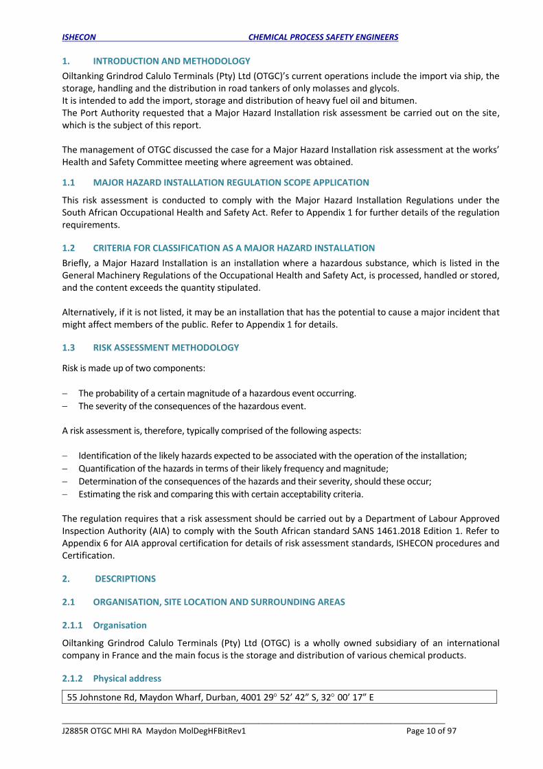
Batches of materials, i.e. molasses, glycol and future heavy fuel oil and bitumen will be offloaded from a ship by its own pump at the quay at either berth 8 or 9 and routed along a berth pipeline into the storage tanks on the OTGC site. Depending on demand, the materials are pumped out of the tanks, and loaded into road tankers for delivery to customers. Refer to Figure 2-6 below.
Figure 2-6 OTGC site process operations
2.2.4 Organisational management
The average personnel compliment (management, administration and operating) on this site is 10. All operations will take place during daytime.
2.2.5 Unique or abnormal conditions
No unique circumstances or abnormal condition were found during the site visit.
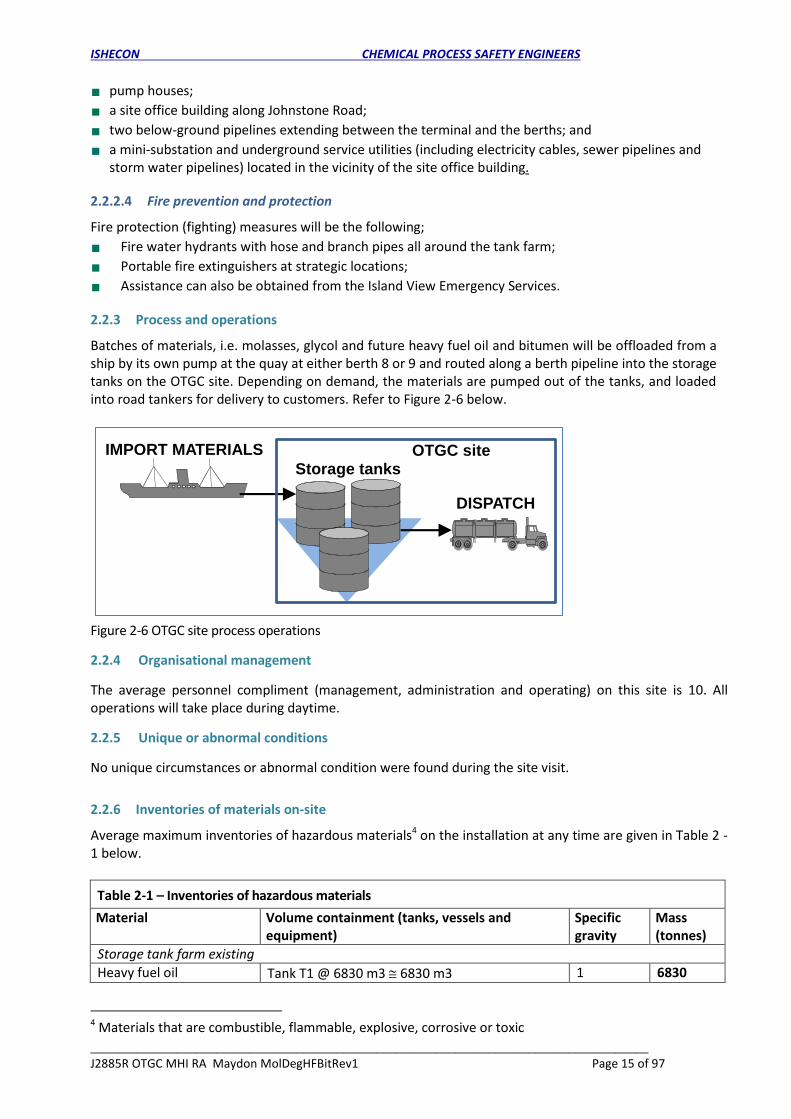
2.2.6 Inventories of materials on-site
Average maximum inventories of hazardous materials4 on the installation at any time are given in Table 2 - 1 below.
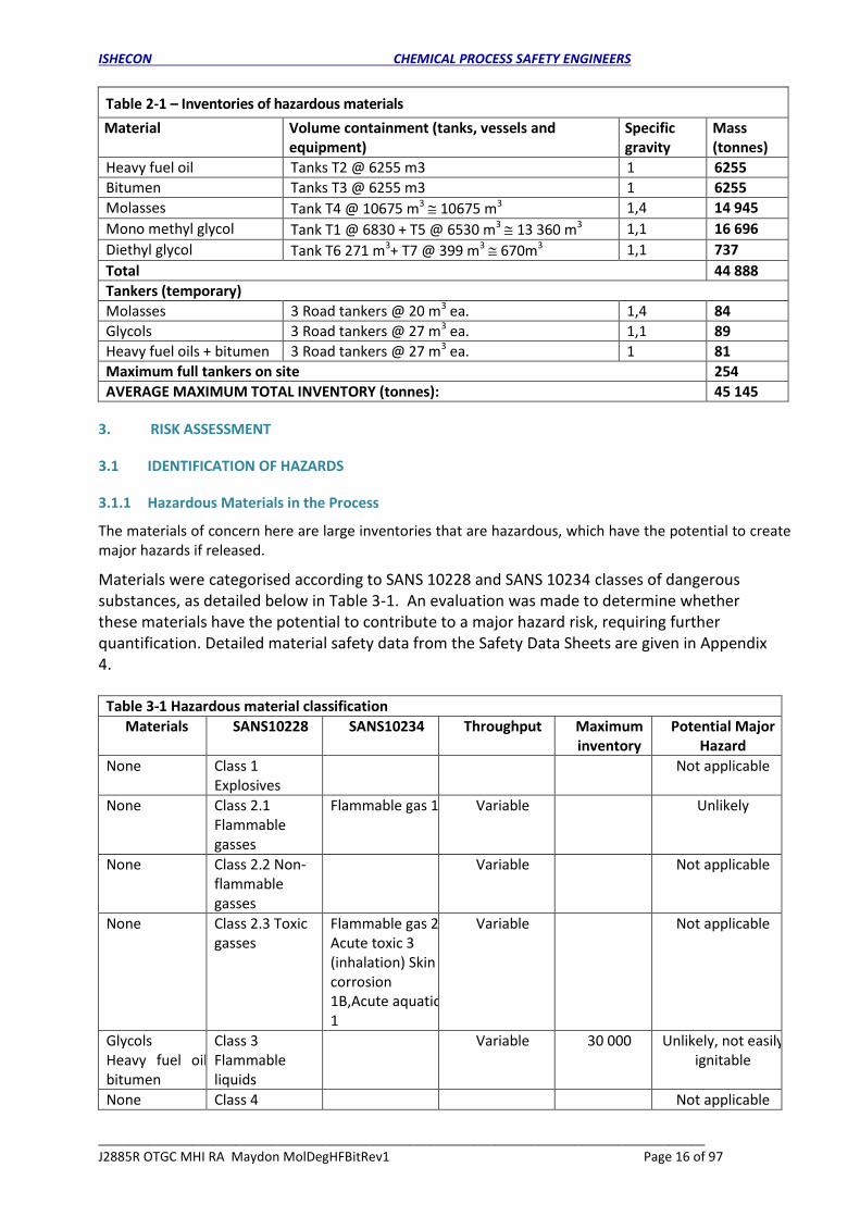
Table 2-1 – Inventories of hazardous materials
Material Volume containment (tanks, vessels and equipment)
Specific gravity
Mass (tonnes)
Storage tank farm existing
Heavy fuel oil Tank T1 @ 6830 m3 6830 m3 1 6830
4 Materials that are combustible, flammable, explosive, corrosive or toxic
IMPORT MATERIALS OTGC siteStorage tanks
DISPATCH
ISHECON CHEMICAL PROCESS SAFETY ENGINEERS
____________________________________________________________________________________
J2885R OTGC MHI RA Maydon MolDegHFBitRev1 Page 16 of 97
Table 2-1 – Inventories of hazardous materials
Material Volume containment (tanks, vessels and equipment)
Specific gravity
Mass (tonnes)
Heavy fuel oil Tanks T2 @ 6255 m3 1 6255
Bitumen Tanks T3 @ 6255 m3 1 6255
Molasses Tank T4 @ 10675 m3 10675 m3 1,4 14 945
Mono methyl glycol Tank T1 @ 6830 + T5 @ 6530 m3 13 360 m3 1,1 16 696
Diethyl glycol Tank T6 271 m3+ T7 @ 399 m3 670m3 1,1 737
Total 44 888
Tankers (temporary)
Molasses 3 Road tankers @ 20 m3 ea. 1,4 84
Glycols 3 Road tankers @ 27 m3 ea. 1,1 89
Heavy fuel oils + bitumen 3 Road tankers @ 27 m3 ea. 1 81
Maximum full tankers on site 254
AVERAGE MAXIMUM TOTAL INVENTORY (tonnes): 45 145
3. RISK ASSESSMENT
3.1 IDENTIFICATION OF HAZARDS
3.1.1 Hazardous Materials in the Process
The materials of concern here are large inventories that are hazardous, which have the potential to create major hazards if released.
Materials were categorised according to SANS 10228 and SANS 10234 classes of dangerous substances, as detailed below in Table 3-1. An evaluation was made to determine whether these materials have the potential to contribute to a major hazard risk, requiring further quantification. Detailed material safety data from the Safety Data Sheets are given in Appendix 4.
Table 3-1 Hazardous material classification
Materials SANS10228 SANS10234 Throughput Maximum inventory
Potential Major Hazard
None Class 1 Explosives
Not applicable
None Class 2.1 Flammable gasses
Flammable gas 1 Variable Unlikely
None Class 2.2 Non-flammable gasses
Variable Not applicable
None Class 2.3 Toxic gasses
Flammable gas 2, Acute toxic 3 (inhalation) Skin corrosion 1B,Acute aquatic 1
Variable Not applicable
Glycols Heavy fuel oil, bitumen
Class 3 Flammable liquids
Variable 30 000 Unlikely, not easily ignitable
None Class 4 Not applicable

ISHECON CHEMICAL PROCESS SAFETY ENGINEERS
____________________________________________________________________________________
J2885R OTGC MHI RA Maydon MolDegHFBitRev1 Page 17 of 97
Flammable solids
None Class 5.1 Oxidisers
Not applicable
None Class 5.2 Peroxides
Not applicable
None Class 6.1 Toxic Flam gas 1, Acute toxic 2 (inhalation), Acute aquatic 1, Chronic aquatic 1
Not applicable
None Class 6.2 Infectious
Not applicable
None Class 7 Radioactive
Not applicable
None Class 8 Corrosives
Skin corrosion 1B, Eye damage 1
Not Possible
Molasses Class 9 Miscellaneous
14950 Not Possible
3.1.2 Environmental Hazards
Environmental effects (biophysical) are not relevant to the Major Hazard Installation Regulations with the exception of elements mentioned in the Environmental Conservation Act of 1973 (replaced by the National Environmental Management Act 1998). Although the effects from a major hazard on the environment may be identified in this assessment, no environmental risk assessment as part of the Major Hazard Installation Risk Assessment will be carried out.
3.1.3 Hazardous Material Interactions
Some hazardous chemicals, when combined, may have flammable, explosive or toxic effects. Molasses, glycols, heavy fuel oil and bitumen are compatible, hence no effects.
3.2 PAST INCIDENTS
A search was carried out to locate instances of incidents, accidents or unusual occurrences, related to major hazards. This will lend support to the hazards identified and show that they can take place. A search was also carried out to locate instances of incidents, accidents or unusual occurrences, related to similar materials handled on-site, which had effects inside and outside of site boundaries. This will lend support to the hazards identified and give a general view of the possible extent of the risk later on in the assessment.
3.2.1.1 OTGC site
No fire, explosion or toxic release incidents have occurred on this terminal since it was originally commissioned. On occasions tankers have driven off during filling, which resulted in spillages of molasses, but the spillages were washed away with water.
3.2.1.2 Worldwide
Incidents related to combustible liquid storage depots were searched for in the IChemE 1999 accident database, and significant incidents are described below.
a) Molasses
There are only four incidents recorded involving molasses; two were related to transport by ship. The other two significant incidents are listed below:

ISHECON CHEMICAL PROCESS SAFETY ENGINEERS
____________________________________________________________________________________
J2885R OTGC MHI RA Maydon MolDegHFBitRev1 Page 18 of 97
UK, 05 April 1989: Deaths 0 Injuries 0. During the discharge of 3350 tonnes of molasses, a failure of a 14” carbon steel line occurred adjacent to a flood protection bank outside the site boundary fence. It was estimated that 520 tonnes of molasses was lost and the cost of this and the ensuing recovery, disposal and investigation was calculated at approximately £35,000 (1989). The molasses line was installed in l94l for molasses receipt at a jetty. Since this time eleven sections have been renewed in 1972 and six sections in 1980. The vessel concerned berthed at the jetty. Hoses were connected and cargo discharged. Of the 520 tonnes of molasses lost, approximately 300 tonnes was recovered, in addition to a lesser quantity of contaminated water. The leak occurred on an 80 ft. long flanged section of line local to a pipe support. The mechanism of failure was thought to be localised external corrosion.
Boston, USA, 15 January 1919. Deaths 21 Injuries 40. A storage tank containing approximately 12,500 tonnes of molasses ruptured. As a result, 9000 tonnes of molasses spilled into the streets of Boston.
b) Glycols
There is no record of major incidents involving mono and di-ethylene glycol.
c) Heavy fuel oil
Honolulu, USA, 15 May 1996, Deaths 0 Injuries 0. Up to 80 m3 of HFO leaked into the bay from a
pipeline leading from a refinery to a Power Plant. Preventative measures included closing the Arizona
Memorial, stopping vessel traffic and using three local response vessels and seven US Navy skimmers
in the spill area.
Warrington, Cheshire, UK, 15 October 1995 Deaths 0 Injuries 0. Leakage at a storage tank caused a
spillage of 2,000 litres of HFO into a river. Pollution occurred over an 8 km stretch of river.
Sendai City, JAPAN, 06 April 1983, Deaths 0 Injuries 0. A crack developed in an HFO line, which caused
spillage and fire.
Location unknown, 01 April 1980, Deaths 0 Injuries 0. An explosion occurred in two balanced off HFO tanks. The most likely cause was water in the bottom of the tank vaporising and leading to a sudden pressure release, rupturing the tank.
d) Bitumen
A study has been made of 73 case histories of incidents involving heated bitumen storage tanks. The
majority of incidents were found to be due to operations such as charging and discharging of tanks,
including overfilling which can lead to lagging fires.
On 8 September 2004 in Italy, a catastrophic failure occurred on bitumen tank T145: the shell and roof
tore off the foundation were projected in vertical direction, and then fell onto a 2nd bitumen storage
tank, causing a massive leakage of bitumen (about 550 t) and hot-oil (about 120 t) at 170° C spreading
all over the area. A pool-fire was then ignited in the TK145 basin, other fires followed involving
equipment in sight, with domino effect on other tanks and on some tank-trucks under loading, located
in the area. The accident had detrimental effects on people and on the environment, but had no off-
site consequences. The principal cause was: - an internal overpressure in the tank caused by explosion
of light flammable hydrocarbons, wrongly introduced into the tank.
4. HAZARD ANALYSIS
4.1 SECTIONS ANALYSED
Ship offloading and berth pipeline
Storage tanks

ISHECON CHEMICAL PROCESS SAFETY ENGINEERS
____________________________________________________________________________________
J2885R OTGC MHI RA Maydon MolDegHFBitRev1 Page 19 of 97
Road tanker loading
4.2 SAFETY MEASURES
The following protective features are incorporated in the design of the installation: 1. Ships are offloaded under supervision from OTGC coordinated with the ship personnel. 2. Ship hose couplings, hoses and berth pipes are checked for leaks before ship offloading. 3. All tanks are provided with level indicators and high alarms in the control room for filling and
emptying as well as for monitoring inventory. 4. On heavy fuel oil, bitumen and glycol there will be an interlock to automatically close the tank’s
filling valve. 5. Storage tanks will be bunded with a collection sump and pump recovery system. Each tank will have
an overflow pipe. 6. Heavy fuel oil, bitumen and glycol road tankers will be filled from the top, via a hose using a batching
meter with automatic shut off. Molasses and oils will be manually filled and will be monitored by an operator to stop filling at the required level.
7. A catchment curb and sump with pump will be provided at the road tanker filling gantries. 8. Open structure for good ventilation to minimise accumulation of flammable or toxic vapours. 9. Pulling away of a road tanker still connected is avoided by not allowing the driver in the cab during
offloading. 10. All tanks, piping and equipment are earthed. 11. Emergency shutdown facilities are provided on the tanker loading filling pumps. 12. Portable fire extinguishers and fire water hydrants with hoses and nozzles. Fire team is on-site, and
assistance is available from local emergency services (15 minutes away). 13. All tanks, pipes and equipment are manufactured from carbon steel. 14. Loading hoses are steel braided rubber.
4.3 CONSEQUENCES
If a volatile combustible material is released, initial dispersion will take place by the jet velocity; a portion will flash off from the jet, while the remainder will fall on the ground and form a pool. Evaporation will take place from the pool, and combine with the flashed off vapour to form a cloud, which will drift away assisted by the wind. As the cloud moves away, it will mix with air and become dispersed and the concentration will decrease as it travels. If there is an ignition source present, a jet fire and a pool fire will result. If the vapours travel downwind into a congested area and is ignited, an explosion could result, otherwise only a flash fire will occur, which could flash fire back to the release source leading again to a jet or pool fire.
4.4 ANALYSIS
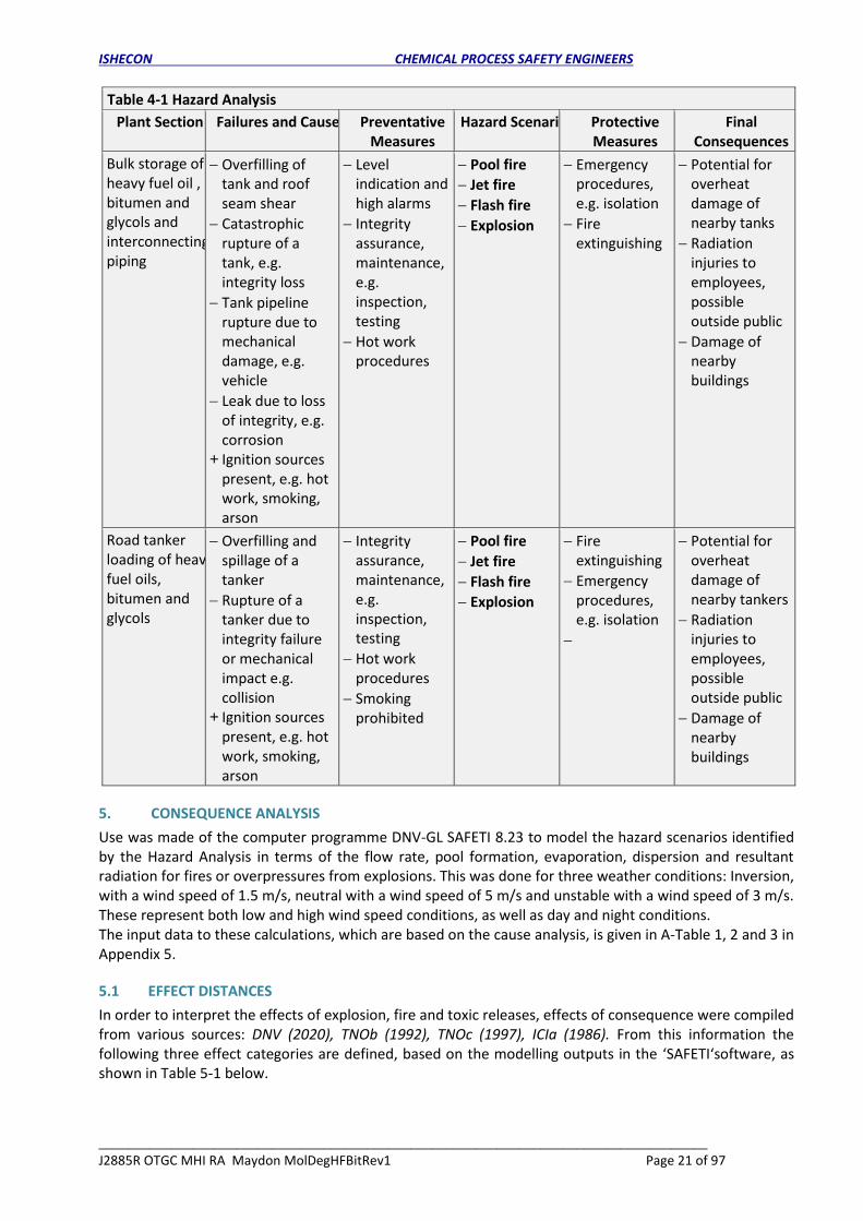
Hazards were analysed as shown in Table 4-1 below. Refer to Appendix 5 for all scenarios considered for modelling, with associated key process input data.
Table 4-1 Hazard Analysis
Plant Section Failures and Causes Preventative Measures
Hazard Scenario Protective Measures
Final Consequences

ISHECON CHEMICAL PROCESS SAFETY ENGINEERS
____________________________________________________________________________________
J2885R OTGC MHI RA Maydon MolDegHFBitRev1 Page 20 of 97
Table 4-1 Hazard Analysis
Plant Section Failures and Causes Preventative Measures
Hazard Scenario Protective Measures
Final Consequences
Hot water boiler (Blast),
Catastrophic rupture of the shell of the boiler, e.g. integrity loss, overheating when empty
Boiler blocked in and heating generating steam and overpressure
+ Failure of overpressure protection and relief devices
Integrity assurance, maintenance, e.g. inspection, testing
Pressure burst
Emergency procedures and evacuation
Damage of nearby tanks, piping and tankers
Injuries to employees, possible outside public
Damage of nearby buildings
Ship offloading Rupture or leak of the ship offloading hose
Integrity assurance, maintenance, e.g. inspection, testing
Pool fire
Jet fire
Flash fire
Explosion
Emergency procedures and evacuation
Damage of nearby tankers,
Injuries to employees, possible public
Berth pipelines for offloading of ships, and transfer across to storage site
Pipeline rupture or leaks due to mechanical damage, e.g. vehicle
Rupture or leak due to loss of integrity, e.g. corrosion
+ Ignition sources present, e.g. hot work, smoking, arson
Integrity assurance, maintenance, e.g. inspection, testing
Hot work procedures
Pool fire
Jet fire
Flash fire
Explosion
Emergency procedures, e.g. isolation
Fire extinguishing
Open area no congestion explosion unlikely
Potential for overheat damage of nearby buildings and structures
Radiation injuries to employees, possible public
ISHECON CHEMICAL PROCESS SAFETY ENGINEERS
____________________________________________________________________________________
J2885R OTGC MHI RA Maydon MolDegHFBitRev1 Page 21 of 97
Table 4-1 Hazard Analysis
Plant Section Failures and Causes Preventative Measures
Hazard Scenario Protective Measures
Final Consequences
Bulk storage of heavy fuel oil , bitumen and glycols and interconnecting piping
Overfilling of tank and roof seam shear
Catastrophic rupture of a tank, e.g. integrity loss
Tank pipeline rupture due to mechanical damage, e.g. vehicle
Leak due to loss of integrity, e.g. corrosion
+ Ignition sources present, e.g. hot work, smoking, arson
Level indication and high alarms
Integrity assurance, maintenance, e.g. inspection, testing
Hot work procedures
Pool fire
Jet fire
Flash fire
Explosion
Emergency procedures, e.g. isolation
Fire extinguishing
Potential for overheat damage of nearby tanks
Radiation injuries to employees, possible outside public
Damage of nearby buildings
Road tanker loading of heavy fuel oils, bitumen and glycols
Overfilling and spillage of a tanker
Rupture of a tanker due to integrity failure or mechanical impact e.g. collision
+ Ignition sources present, e.g. hot work, smoking, arson
Integrity assurance, maintenance, e.g. inspection, testing
Hot work procedures
Smoking prohibited
Pool fire
Jet fire
Flash fire
Explosion
Fire extinguishing
Emergency procedures, e.g. isolation
Potential for overheat damage of nearby tankers
Radiation injuries to employees, possible outside public
Damage of nearby buildings
5. CONSEQUENCE ANALYSIS
Use was made of the computer programme DNV-GL SAFETI 8.23 to model the hazard scenarios identified by the Hazard Analysis in terms of the flow rate, pool formation, evaporation, dispersion and resultant radiation for fires or overpressures from explosions. This was done for three weather conditions: Inversion, with a wind speed of 1.5 m/s, neutral with a wind speed of 5 m/s and unstable with a wind speed of 3 m/s. These represent both low and high wind speed conditions, as well as day and night conditions. The input data to these calculations, which are based on the cause analysis, is given in A-Table 1, 2 and 3 in Appendix 5.
5.1 EFFECT DISTANCES
In order to interpret the effects of explosion, fire and toxic releases, effects of consequence were compiled from various sources: DNV (2020), TNOb (1992), TNOc (1997), ICIa (1986). From this information the following three effect categories are defined, based on the modelling outputs in the ‘SAFETI‘software, as shown in Table 5-1 below.

ISHECON CHEMICAL PROCESS SAFETY ENGINEERS
____________________________________________________________________________________
J2885R OTGC MHI RA Maydon MolDegHFBitRev1 Page 22 of 97
Table 5-1 Effect categories
Category 1 2 3
Least severe Moderately severe Most severe
Fire radiation kW/m2 4 12,5 37,5
Effects from a pool or jet fire or a fire ball for 10 s
0 % fatal, pain, blistering ~ 0 - 1% fatal, 2nd degree burns
100% fatal
Flash fire radius m Radius from the release to ½ the Lower Flammable Limit (LEL)
Effects from a flash fire 100 % fatal
Explosion overpressure kPa
2 13,8 20,7
Explosion effect on people in open
0 % fatal
0,1% ear drum rupture
0 % fatal
1% ear drum rupture
0 % fatal
10% ear drum rupture 0 % fatal
Explosion effect on people inside masonry building
0 % fatal 1 % fatal 20 % fatal
Explosion effects on masonry buildings
No masonry damage, safe building. 10-20 % windows broken.
Minor structural damage to houses. Missile limit
Masonry damage. 100 % windows broken.
Partial collapse of walls and roofs of houses.
Steel building damage. 100 % windows broken.
Steel frame buildings distorted and pulled away from foundation. Frameless, self- framing steel building demolished, rupture of storage tanks
Toxic concentration ERPG 1 ERPG 2 ERPG 3
Toxic effects on people Suffer only mild transient health effects and objectionable odour
Not suffer irreversible or other serious health effects or symptoms that could impair ability to take protective action
Will not suffer life threatening health effects
Severity effect distances for the 3 effect categories, were determined by the consequence modelling. Events, which have a serious effect the longest distance away from the source (hazard end points), are summarised in Table 5-2 below, for each severity category.
Table 5-2 Events with maximum effect distances
Category 1 2 3
Severity Least severe
Moderate severe
Most severe
Event
Effect Maximum effect distance m
Pool fire 82 37 28 Bitumen tank burst and deliberately ignited
Jet fire 47 35 33 Bitumen tank burst and deliberately ignited
Fire ball NA
Flash fire 39 Bitumen tank burst and deliberately ignited NA

ISHECON CHEMICAL PROCESS SAFETY ENGINEERS
____________________________________________________________________________________
J2885R OTGC MHI RA Maydon MolDegHFBitRev1 Page 23 of 97
Table 5-2 Events with maximum effect distances
Category 1 2 3
Severity Least severe
Moderate severe
Most severe
Event
Effect Maximum effect distance m
Explosion 48 41 40 Bitumen tank burst and deliberately ignited
Bleve blast NA NA NA NA
Toxic release NA NA NA NA
Toxic 1% lethal NA NA
NA Not applicable, effect does not occur
The Table 5-2 above shows that if any of the events had to occur, one could possibly expect, as a minimum, some serious hazardous effects as far away as 39 m for a flash fire from a bitumen tank burst. In other words, this is the distance up to which injuries (which could include fatalities) might occur. These results do not include any escape or shielding factors, i.e. it is for a person in the open, stationary at that distance. Neither do these results include likelihood (frequency) of the events happening. Account is only taken of the probability.
5.1.1 Hazard Effect Zones
Severity is further illustrated by graphical outputs of some of the significant effects on plot plans of the site and surrounding areas.
5.1.1.1 Fire Radiation
The following fire radiation radii for various releases are shown on maps of the site on the figures below.
Figure 5-1 Pool fire radiation 12,5W/m2 for glycol, heavy fuel oil and bitumen ignited releases

ISHECON CHEMICAL PROCESS SAFETY ENGINEERS
____________________________________________________________________________________
J2885R OTGC MHI RA Maydon MolDegHFBitRev1 Page 24 of 97
Figure 5-2 Jet fire radiation 12,5 kW/m2 effects for glycol, heavy fuel oil, bitumen tanks and berth pipe leaks
Figure 5-3 Flash fire radiation cover circles (green) for glycol, heavy fuel oil and bitumen ignited releases

ISHECON CHEMICAL PROCESS SAFETY ENGINEERS
____________________________________________________________________________________
J2885R OTGC MHI RA Maydon MolDegHFBitRev1 Page 25 of 97
5.1.1.2 Explosion overpressures
Figure 5-4 Explosion 13,79 kPa overpressure effect zones for ignited glycol, heavy fuel and bitumen tank bursts
5.1.1.3 Toxic effects
There are no toxic effect zones for releases to display on maps of the site.
5.1.1.4 Fatal effects
The fatal effect zones are represented in the previous consequence effects display maps as a 12,5 kW/m2 radiation level for a 1% chance of a fatality and 13,79 kPa overpressure level for a 1% chance of a fatality for explosion.
5.2 Qualification as a Major Hazard Installation
The entire Island View complex including Maydon Wharf is owned by SA Ports Authority and activities other than that of OTGC outside the boundary are regarded as public with respect to OTGC. Areas outside the Island View complex may be regarded as sensitive public areas. None of the materials to be handled and stored on the OTGC site is listed in the Schedule A of the General Machinery Regulations in the OHS Act and, therefore, the OTGC site is not classified as a compulsory Major Hazard Installation. Molasses is not listed as hazardous materials in SANS 10228, and can therefore be excluded from further consideration in terms of a major hazard installation. It can be seen, though, from the results in the previous section, including radiation and flash fire circles displayed on maps of the site, that the fire 12,5 kW/ m2 radiation effects and 13.79 kPa explosion overpressures , as set out in the criteria in Appendix 1, does not significantly extend outside the OTGC site boundaries or even the Island View complex. Thus the OTGC installation does not have the potential to cause serious effects on members of the public or on outside sensitive areas. Hence the OTGC site was not classified as a Major Hazard Installation.
5.2.1 Notification of Major Hazard Installation
As this facility is not a Major Hazard Installation, notifications to the authorities are not required.
ISHECON CHEMICAL PROCESS SAFETY ENGINEERS
____________________________________________________________________________________
J2885R OTGC MHI RA Maydon MolDegHFBitRev1 Page 26 of 97
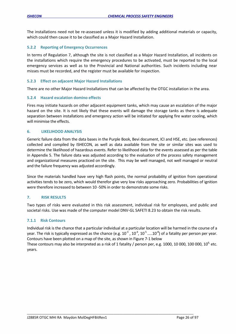
The installations need not be re-assessed unless it is modified by adding additional materials or capacity, which could then cause it to be classified as a Major Hazard Installation.
5.2.2 Reporting of Emergency Occurrences
In terms of Regulation 7, although the site is not classified as a Major Hazard Installation, all incidents on the installations which require the emergency procedures to be activated, must be reported to the local emergency services as well as to the Provincial and National authorities. Such incidents including near misses must be recorded, and the register must be available for inspection.
5.2.3 Effect on adjacent Major Hazard Installations
There are no other Major Hazard Installations that can be affected by the OTGC installation in the area.
5.2.4 Hazard escalation domino effects
Fires may initiate hazards on other adjacent equipment tanks, which may cause an escalation of the major hazard on the site. It is not likely that these events will damage the storage tanks as there is adequate separation between installations and emergency action will be initiated for applying fire water cooling, which will minimise the effects.
6. LIKELIHOOD ANALYSIS
Generic failure data from the data bases in the Purple Book, Bevi document, ICI and HSE, etc. (see references) collected and compiled by ISHECON, as well as data available from the site or similar sites was used to determine the likelihood of hazardous events. Refer to likelihood data for the events assessed as per the table in Appendix 5. The failure data was adjusted according to the evaluation of the process safety management and organizational measures practiced on the site. This may be well managed, not well managed or neutral and the failure frequency was adjusted accordingly. Since the materials handled have very high flash points, the normal probability of ignition from operational activities tends to be zero, which would therefor give very low risks approaching zero. Probabilities of ignition were therefore increased to between 10 -50% in order to demonstrate some risks.
7. RISK RESULTS
Two types of risks were evaluated in this risk assessment, individual risk for employees, and public and societal risks. Use was made of the computer model DNV-GL SAFETI 8.23 to obtain the risk results.
7.1.1 Risk Contours
Individual risk is the chance that a particular individual at a particular location will be harmed in the course of a year. The risk is typically expressed as the chance (e.g. 10-3 , 10-4, 10-5 …..10-8) of a fatality per person per year. Contours have been plotted on a map of the site, as shown in Figure 7-1 below These contours may also be interpreted as a risk of 1 fatality / person per, e.g. 1000, 10 000, 100 000, 106, etc. years.

ISHECON CHEMICAL PROCESS SAFETY ENGINEERS
____________________________________________________________________________________
J2885R OTGC MHI RA Maydon MolDegHFBitRev1 Page 27 of 97
Figure 7-1 Individual risk contours as the chance of a fatality /person/year (no risk identified)
7.1.2 Risk Profiles
On the map of the risk contours in Figure 7-1 above, a diagonal(southwest to northeast direction) ‘transect’ A – B was drawn, which produced the risk profile as shown on the graph in Figure 7-2 below. This graph plots the variation of unmitigated individual risks (no allowance for escape or wind direction) against distance over the site along the ‘transect’. This shows that the maximum risk on the site is a 3 * 10-6 chance of a fatality per person to which an employee would be exposed.
Figure 7-2 – Risk profile along a transect A – B across the risk contours Similarly, the risk profile anticlockwise from the north corner anticlockwise all the way around along the boundary line was obtained as shown on the graph in Figure 7-3 below. Again this shows the maximum risk a member of the public at the site boundary could be exposed is a 2 * 10-7 chance of a fatality per person per year.
A
B

ISHECON CHEMICAL PROCESS SAFETY ENGINEERS
____________________________________________________________________________________
J2885R OTGC MHI RA Maydon MolDegHFBitRev1 Page 28 of 97
Figure 7-3 – Risk profile along site boundary
7.1.3 Societal Risk
Societal risk depends on the population distribution normally surrounding the site, as well as whether persons are indoors or outdoors, i.e. their ability to escape from the hazard area. Societal risk is a way to estimate the chances of numbers of people being harmed from an incident. The likelihood of the primary event (an accident at a major hazard plant) is still a factor, but the consequences are assessed in terms of level of harm and numbers affected, to provide an idea of the scale of an accident in terms of numbers killed or harmed. Evaluation of societal risk is useful for town planning as it gives an indication of how many of the population may be harmed. Population area for the OTGC site on a map is demarcated as shown in Figure 7-4 below.
Figure 7-4 – OTGC site, and surrounding population areas
An estimate of the number of people in the populated areas was done and the population density was calculated based on the surface area. A probability that people would be indoors was assigned to each population area, based on the guidelines Green Book 1992. See Table 7-1 below.

ISHECON CHEMICAL PROCESS SAFETY ENGINEERS
____________________________________________________________________________________
J2885R OTGC MHI RA Maydon MolDegHFBitRev1 Page 29 of 97
Table 7-1 – Population data
Time
Population area Harbour area
Day People 14 000
Population density (persons / m2
0.08
Fraction indoors 0,93
Night People 2000
Population density (persons / m2
0,002
Fraction indoors 0,99
Societal risks were determined by using the individual risks to calculate the number of fatalities in a specific population area, taking account of the population density, the probability that people will be indoors, the wind direction distribution and ignition probabilities associated with the population and other activities. Societal risk is then expressed in frequency – fatality (F-N) curves as shown on a graph in Figure 7-5 as a blue curve denoted ‘Combination 1’, which is the combination of day and night societal risk curves. In this evaluation the population on-site was excluded. Incidents, which will incur a large number of fatalities, are less likely to occur. There is a lower limit line (green), below which the risks are totally acceptable and an upper limit line (red) above which risks are totally unacceptable.
Figure 7-5 – Societal risk F-N cure, (frequency / year versus number of fatalities)
8. ENVIRONMENTAL
Large spills of molasses into waterways or into the sea are unlikely to be harmful to aquatic life, except maybe enhancing the growth and multiplication of organisms and plant life. Ethylene glycol is miscible with water and is also toxic towards aquatic life. Heavy fuel oil and bitumen are not miscible with water and would destroy aquatic life in the harbour. Bitumen will most likely solidify when entering the harbour water, thus minimising the spread of material reducing damage to aquatic life.
9. RISK JUDGEMENT
9.1 WORKFORCE INDIVIDUAL RISK
People inside the boundaries of the site are looked upon as being employees who are considered to be different from members of the public as far as safety is concerned. They have been trained in handling all the potential hazards on the site, i.e. emergency procedures, availability of suitable protective equipment (PPE). Criteria are as follows: Risk > a 1*10-3 chance of a fatality per person per year: Unacceptably high
ISHECON CHEMICAL PROCESS SAFETY ENGINEERS
____________________________________________________________________________________
J2885R OTGC MHI RA Maydon MolDegHFBitRev1 Page 30 of 97
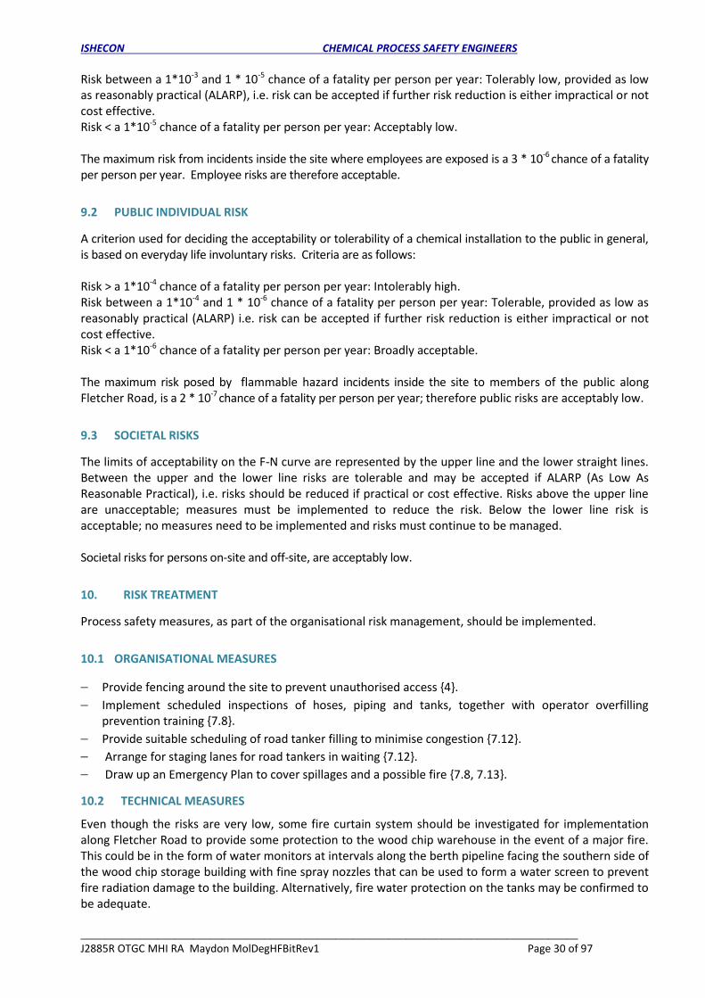
Risk between a 1*10-3 and 1 * 10-5 chance of a fatality per person per year: Tolerably low, provided as low as reasonably practical (ALARP), i.e. risk can be accepted if further risk reduction is either impractical or not cost effective. Risk < a 1*10-5 chance of a fatality per person per year: Acceptably low. The maximum risk from incidents inside the site where employees are exposed is a 3 * 10-6 chance of a fatality per person per year. Employee risks are therefore acceptable.
9.2 PUBLIC INDIVIDUAL RISK
A criterion used for deciding the acceptability or tolerability of a chemical installation to the public in general, is based on everyday life involuntary risks. Criteria are as follows: Risk > a 1*10-4 chance of a fatality per person per year: Intolerably high. Risk between a 1*10-4 and 1 * 10-6 chance of a fatality per person per year: Tolerable, provided as low as reasonably practical (ALARP) i.e. risk can be accepted if further risk reduction is either impractical or not cost effective. Risk < a 1*10-6 chance of a fatality per person per year: Broadly acceptable. The maximum risk posed by flammable hazard incidents inside the site to members of the public along Fletcher Road, is a 2 * 10-7 chance of a fatality per person per year; therefore public risks are acceptably low.
9.3 SOCIETAL RISKS
The limits of acceptability on the F-N curve are represented by the upper line and the lower straight lines. Between the upper and the lower line risks are tolerable and may be accepted if ALARP (As Low As Reasonable Practical), i.e. risks should be reduced if practical or cost effective. Risks above the upper line are unacceptable; measures must be implemented to reduce the risk. Below the lower line risk is acceptable; no measures need to be implemented and risks must continue to be managed. Societal risks for persons on-site and off-site, are acceptably low.
10. RISK TREATMENT
Process safety measures, as part of the organisational risk management, should be implemented.
10.1 ORGANISATIONAL MEASURES
Provide fencing around the site to prevent unauthorised access {4}.
Implement scheduled inspections of hoses, piping and tanks, together with operator overfilling prevention training {7.8}.
Provide suitable scheduling of road tanker filling to minimise congestion {7.12}.
Arrange for staging lanes for road tankers in waiting {7.12}.
Draw up an Emergency Plan to cover spillages and a possible fire {7.8, 7.13}.
10.2 TECHNICAL MEASURES
Even though the risks are very low, some fire curtain system should be investigated for implementation along Fletcher Road to provide some protection to the wood chip warehouse in the event of a major fire. This could be in the form of water monitors at intervals along the berth pipeline facing the southern side of the wood chip storage building with fine spray nozzles that can be used to form a water screen to prevent fire radiation damage to the building. Alternatively, fire water protection on the tanks may be confirmed to be adequate.

ISHECON CHEMICAL PROCESS SAFETY ENGINEERS
____________________________________________________________________________________
J2885R OTGC MHI RA Maydon MolDegHFBitRev1 Page 31 of 97
11. LAND USE PLANNING
There is a twofold responsibility placed on the local authorities when dealing with a Major Hazard Installation (See regulation 9) to ensure that…
an existing Major Hazard Installation presents sufficiently low risks to existing neighbouring facilities and communities;
new developments in the area potentially affected by the installation are suitable for the risk level in the area.
Development zones are defined in Table 11-1 below.
Table 11-1 Development zones
Inner zone (IZ): Greater than 10 in one million chances of receiving a dangerous dose (> 1 * 10-5). Most restrictions would apply and only the least sensitive types of development would be allowed.
Middle zone (MZ): Between 1 and 10 in one million (> 1 * 10-6 and < 1 * 10-5). Restrictions on vulnerable developments would apply.
Outermost zone (OZ): Less than 1 in one million (<1 * 10-6). Few or limited restrictions would apply for developments.
Beyond these three zones no specific restrictions are advised (i.e. risks less than 0.3 in a million).
Due to the lack of significant risks, only middle and an outer zone was demarcated on a map of the areas around the site in Figure 11-1 below. It can be seen that all the allowed development zones are within the site boundaries.
Figure 11-1 Site showing no demarcated development restriction zone The site is situated on industrially zoned land with other factories all around. Land-use planning restrictions are proposed as listed in Table 11-2 below.
Table 11-2 Development restrictions
Development Type Description Restriction
Industrial use
Workplaces with buildings with <100 occupants and <3 storeys per building.
None
Workplaces containing buildings with >100 occupants and 3 or more storeys per building.
Not allowed within Inner Zone
Residential Any housing developments, even those with less than 30 dwellings per hectare, except small in-fill projects of one or two units which could be allowed.
Not allowed within Inner Zone
MIDDLE ZONE
OUTER ZONE

ISHECON CHEMICAL PROCESS SAFETY ENGINEERS
____________________________________________________________________________________
J2885R OTGC MHI RA Maydon MolDegHFBitRev1 Page 32 of 97
Table 11-2 Development restrictions
Development Type Description Restriction
High density developments such as large blocks of flats Not allowed within Inner and Middle Zones
Other Hospitals, old-age homes, crèches, schools, large outdoor entertainment facilities (theme parks, sports stadia), informal housing, etc.
Not allowed within Inner, Middle or Outer Zones
Note that the above are merely proposals and any decisions regarding land-use planning are entirely the responsibility of the local authorities.
12. EMERGENCY PLAN
There are usually three levels of emergency response to be considered:
Installation emergencies
On-site emergencies
Emergencies that involve the outside public and local authorities.
12.1 INSTALLATION EMERGENCIES
These are normally of a small nature, e.g. leaks and small fires and can in almost all cases be dealt with by the operator. It is included as part of the operating procedures, which are simple and straightforward; therefore, these were not considered any further.
12.2 ON-SITE EMERGENCIES
These are emergencies that result from a fire, an explosion and toxic releases, which usually only have an effect on the installation itself and on surrounding installations within the boundaries of the site. There is an emergency plan at present and it is attached in Appendix 7. This plan was recently evaluated and revised. The handling of heavy fuel oil and bitumen should be included in the emergency plan.
12.3 OFF-SITE EMERGENCIES
There is no evidence of an off-site emergency plan for the installation. This is the responsibility of the local authority emergency services and needs to be prepared, reviewed and updated by the nearest local emergency services.
13. CONCLUSIONS AND DISCUSSION
From the above analyses, risk assessment and emergency plan discussions, the following conclusions can be drawn:
13.1 INCIDENT IDENTIFICATION
In terms of material hazards associated with the process or operations there are …
combustible liquids (ethylene glycol, heavy fuel oil and bitumen)
non-hazardous liquids (molasses) Causes of hazards for the plant and equipment used are…
potential bursting and leaks on ship offloading hoses
burst and leaks of storage tanks and road tankers,
overfilling of storage tanks and road tankers,
potential rupture and leaks of piping,
deliberate ignition of releases resulting in pool, jet and flask fires or explosions.

ISHECON CHEMICAL PROCESS SAFETY ENGINEERS
____________________________________________________________________________________
J2885R OTGC MHI RA Maydon MolDegHFBitRev1 Page 33 of 97
13.2 SEVERITY AND RISKS
13.2.1 Severity
Operation of the upgraded OTGC installations does not have the potential to seriously affect members of adjacent installations and the public outside the site boundary in the event of fires and explosions. In addition, the risks are very low and are only presented because the probability of ignition was increased, mainly to cover arson. Thus, the OTGC site was not classified as a Major Hazard Installation. Materials handled and stored on the site are not highly toxic, but nevertheless, a release into the environment (harbour water) would cause serious damage, but will not result in irreversible consequences.
13.2.2 Individual risks
Maximum risks at the centre of the site is approximately a 3 * 10-6 chance of a fatality per person per year and only reduce to less than a 2 *10-7 chance of a fatality per person per year at the boundary, which is in the public domain. Main contributions from the installation to a total risk of 7,9 * 10-8 at the ranking point (adjacent wood chip warehouse) are: Bitumen tanker burst 100%
13.2.3 Societal risks
As shown by the F-N curve, societal risks, which include the employees, are low. Contributions to total societal risk of 8,3 *10-6 are: Bitumen tanker burst 83% Bitumen tanker leak 15% Ship bitumen hose burst 0,96% Ship bitumen hose leak 0,79%
13.3 RISK ACCEPTABILITY
Overall, individual risks from the OTGC installation posed to employees and the public, as well as societal risks are acceptably low.
13.4 RISK REDUCTION
Major hazard risk can only be further reduced by providing additional fire protection for the wood chip warehouse. This may be expensive or impractical. A process safety system should be formally implemented.
13.5 VALIDITY OF THE RISK ASSESSMENT
There are no technical uncertainties or sensitivities. This risk assessment is valid for the information provided by the operating personnel, i.e. process and operations descriptions together with the inventories.
13.6 LAND USE
The area around the site is built-up. Establishment of housing, schools, hospitals, care centres and other sensitive development should be avoided.
13.7 INTEGRITY ASSURANCE
While it is fine for an installation to have been designed and constructed according to high standards, it is also necessary to ensure that the integrity is maintained and any deterioration is detected and plant and equipment are restored to the original condition.

ISHECON CHEMICAL PROCESS SAFETY ENGINEERS
____________________________________________________________________________________
J2885R OTGC MHI RA Maydon MolDegHFBitRev1 Page 34 of 97
It is therefore necessary to monitor the condition of plant and equipment by means of scheduled inspections.
13.8 Operating Information
Operating, technical and training manuals, and a formal and standard Piping and Instrumentation (P & I) diagram for the installations, are available. This information should be updated whenever any modification on the installations is made, because correct information is essential for proper operation and identification of valves, piping, equipment and instrumentation whenever maintenance is carried out. Accidents originating from modifications or from operations based on inadequate information will thus be avoided. A modification administrative system to avoid unsafe modifications is in place.
13.9 Training
Proper training of operating personnel who handle toxic and flammable materials is carried out to ensure that they understand the dangers, and how to handle any emergencies.
13.10 Installation Security
Although the risk from sabotage has lately almost disappeared, suitable security systems are in place to secure the installations against intruders and unauthorised access, which have the potential to create a major hazard.
13.11 FIRE PROTECTION
Fire protection is in the form of a trained on-site fire team and fire hydrants with hoses, which should be adequate. In order to provide additional protection on the southern side of the wood chip storage, e.g. fire monitors should be provided along the berth pipe road adjacent to the road that can be set up to form a water screen to prevent serious fire radiation effects at the wood chip storage building. It is unlikely that this will ever be used due to the low risks. In addition a heavy fuel oil or bitumen fire heat radiation is not likely to penetrate through the woodchip corrugated iron wall to cause a fire inside in the time that a heavy fuel oil or bitumen fire is extinguished.
13.12 INSTRUMENTATION
Basic instrumentation exists, comprising a local level indicator and high alarm on the storage tanks.
14. RECOMMENDATIONS
This major hazard risk assessment has highlighted potential areas for improvement both in terms of possible enhancements to this assessment and in terms of improvement opportunities on the plant, and the following recommendations were made. (Note that the numbers in the { } brackets refer to the sections where the background and reasons are detailed). (i) Review the risk assessment whenever the installation is modified or expanded and it could
become a Major Hazard Installation {5.2.1}. (ii) Notify the local emergency services of any incidents that activated the emergency procedures
{5.2.1}. (iii) Keep a register of all near miss incidents related to the operation of the installation {5.2.2}. (iv) Investigate and implement process safety management measures as proposed {10}. (v) Include heavy fuel oil and bitumen in the on–site emergency procedure {12.2}. (vi) Request the local emergency services to draw up the off-site emergency plan {12.3}. (vii) Implement or confirm suitable fire protection systems are in place to minimise fire damage to
the adjacent wood chip warehouse {13.9}.

ISHECON CHEMICAL PROCESS SAFETY ENGINEERS
____________________________________________________________________________________
J2885R OTGC MHI RA Maydon MolDegHFBitRev1 Page 35 of 97
15. REFERENCES
1. Lex Patria Publishers, Occupational Health & Safety Act 85 of 1993. 2. Weiss G 1986, Hazardous Chemical Data Book 2nd ed. - Noyes Data Corporation. 3. Genium Material Safety Data sheet Collection, Genium publishing, New York 4. Pirhonen P, Journal of Loss Prevention in the Process Industries 1992, Vol 5 Number 5 pg. 292 5. Lees, F P, Loss Prevention in the Process Industries, Vol 1, Butterworths, London, 1980. 6. IChemE, 1999, “The Accident Database – version 4.1”, CD-ROM, Rugby, UK. 7. ICI, Process Safety Guide No 10, 1986- Risk Assessment Methodology. 8. HSE, Reducing Risks, Protecting People, HSE Books, Section 132, 2001. 9. Kletz T, Still Going Wrong, Case Histories of Process Plant Disasters and How They Could Have Been
Avoided, Gulf Professional Publishing, 2003. 10. Purple Book, Guidelines for Quantitative Risk Assessment, CPR 18E, 1999. 11. ICIa, Process Safety Guide No 10, Risk Assessment Methodology, 1986 12. ICIb, Process Safety Guide No 14, Reliability Data, September 1992. 13. Tyson, Diab, Preston-Whyte, Stability Wind Roses for Southern Africa, 1979 Paper 21 University of
the Witwatersrand. 14. Climate of SA Part 12, Surface Winds, Weather Bureau, WB 38 October 2019. 15. SANSa, South African National Standard, Major hazard installation — Risk assessments, SANS
1461:2018, Edition 1, 2018. 16. SANSb, Major hazard installation: Emergency response planning, SANS1514:2018. 17. TNOa, rivm reference Manual Bevi Risk Assessment, version 3.2, 1 July 2007. 18. DNV, Safeti software documentation, 2020. 19. TNOb, Roos AJ, Methods for determining of possible damage, Green Book, CPR 16E, 1st Edition 1992. 20. TNOc, Methods for calculation of physical effects, Part 1 &2, Yellow Book, CPR 14E, 1997. 21. HSE Guidance Document, HID’s approach to ‘As low As Reasonably Practical’ ALARP, decisions,
(SPC/Permissioning/09), 2010. END of report......................................................................................................... APPENDIX 1 GENERAL RISK ASSESSMENT 1 THRESHOLD CRITERIA FOR CLASSIFICATION OF A MAJOR HAZARD INSTALLATION
Definitions in the regulations state that a Major Hazard Installation is an installation where a substance is stored that is listed in Schedule A of the General Machinery regulations of the Occupational Health and Safety Act and the quantity exceeds those stipulated. The materials handled are hazardous substances listed in SANS 10228 under both the specific and generic type names. It is an installation where a substance is produced, processed, used, handled or stored in such a form and quantity that it has the potential to cause a major incident. A Major Incident is an event or occurrence of catastrophic proportions resulting from the use of plant and machinery, or from activities at a workplace. This may be interpreted in technical terms as follows:
Catastrophic relates to the effects on the general public i.e. persons outside the boundary of the premises of the installation.
People entering the premises through gates, although members of the public will be regarded as employees for the duration they remain on the premises.
A fatality to one or more members of the public may be regarded as catastrophic.

ISHECON CHEMICAL PROCESS SAFETY ENGINEERS
____________________________________________________________________________________
J2885R OTGC MHI RA Maydon MolDegHFBitRev1 Page 36 of 97
Exposing a member of the public to hazard effects which exceeds the following thresholds:
Thermal radiation: 12 kW / m2 for 1 minute.
Engulfed in a flash fire
Blast overpressure: 14 kPa.
Toxic gas dose: Equivalent Emergency Planning Response Guideline ERPG 3 for 1 hour and chance of fatality > 1 %.
Toxic liquid drench: More than 50 % body coverage [severe injuries or fatalities].
2 APPROACH USED IN THIS RISK ASSESSMENT The focus of this assessment is on those hazards leading to injuries or fatalities that can affect the outside public or neighbouring installations. It is therefore not a detailed audit of all the possible risks to plant equipment and operating personnel etc. The expertise and knowledge of the operating personnel were initially used to determine which events are most likely to be significant and furthermore which of these significant events is likely to affect the outside population and installations. Thereafter all the categories of hazards in each area were evaluated qualitatively and quantitatively to confirm which hazards are major hazards. Therefore general hazards from the storage of large quantities of hazardous materials, such as burns and possible death of personnel, were deemed to be localised and not able to affect the outside public or neighbouring installations, and are hence not considered in detail in this report. Similarly, issues such as ecological, environmental and financial risks within the organisation were not considered. The assessment was carried out to ISHECON Work Procedures WP301 – MHI RA Assignment Administration and WP302 – MHI RA Methodology. An appointed risk assessor, in accordance with ISHECON Work Procedure 102- Training and appointment of personnel did the assessment work. The risk assessment has been approved by a signatory listed on the SANAS certificate. The methodology followed can therefore be summarised as follows:
Description of the plant, the location, and the meteorological conditions; Identification of all the possible categories of hazards, by listing all the materials used in the process with their hazardous properties, and by dividing the plant into sections with consideration of the possible equipment related hazards in each section; Selecting in a qualitative manner, the worst incidents within all these categories and then quantifying these; Evaluating the consequences of the incidents in order to determine which events were likely to affect only the local plant and which could possibly effect the outside public (potential major hazards); Quantification of consequences in detail in terms of toxic cloud movements, explosion damage circles etc.; Major hazards with potential consequences which may affect the local plant were not considered further, while the severity of the remaining major hazards was determined and a frequency of occurrence estimated; Estimating the risk and comparison with certain acceptability criteria; Reviewing emergency procedures in the light of the possible major incidents; Drawing of conclusions and proposing recommendations. APPENDIX 2 APPLICABLE REGULATIONS AND STANDARDS
The legal requirements pertaining to the identified impacts are listed below:
Occupational Health and Safety Act (Act 85 of 1993) and its regulations.
Maritime Safety Regulations of 1994.

ISHECON CHEMICAL PROCESS SAFETY ENGINEERS
____________________________________________________________________________________
J2885R OTGC MHI RA Maydon MolDegHFBitRev1 Page 37 of 97
International Maritime Dangerous Goods (IMDG) Code and the National Road Traffic Act (Act 93 of 1996).
Port Rules of the National Ports Act (Act 12 of 2005) (March 2009).
Merchant Shipping Act (Act 57 of 1951).
Major Hazard Installation Regulations under the Occupational Health and Safety Act (Act 85 of 1993),
revised in July 2001.
National Environmental Management Act (Act 107 of 1998, as amended).
Environmental Conservation Act (Act 73 of 1989).
APPENDIX 3 WIND WEATHER DATA 1 GENERAL WEATHER INFORMATION: DURBAN Atmospheric Pressure - 100 kPa Abs Day temperature - 26 o C Night temperature - 16 Relative Humidity Day - 65 % Relative Humidity Night - 80% 2 WIND SPEEDS, DIRECTIONS AND THERMAL STABILITIES The following information sources were used:
Weather Bureau data from Durban Airport weather office from 2018 to 2020.
Tyson P D, Diab R D & Preston-Whyte R A, Stability Wind Roses for Southern Africa, Environmental Studies Occasional Paper No 21, Dept. Of Geography & Environmental Studies, Univ. Wits, Jhb. RSA.
Three Pasquill stability conditions are normally applicable namely: - Unstable: Sunny hot day (A, B, C). - Neutral: Overcast day or night (D). - Stable: Clear, cold night (E, F). The above choice was based on climate data for the east coast area (Tyson, Diab, Preston 1979) with the following distribution over a year (information for mornings were not available): Condition Night Day Total (01:30) (13:30) Unstable 2 58 30 Stable 54 39 47 Inversion 44 3 23 100% 100% 100% The time during a year that the wind blows in given directions were scaled to a 100 % and given in the table below.

ISHECON CHEMICAL PROCESS SAFETY ENGINEERS
____________________________________________________________________________________
J2885R OTGC MHI RA Maydon MolDegHFBitRev1 Page 38 of 97
APPENDIX 4 MATERIAL DATA
Tables in the following sections summarise the properties, safety, health and environmental information of the key chemicals extracted from Safety Data Sheets and the literature (Weiss 1986 & Genium).
15.1 Physical and flammable properties
Physical properties shown in Table 6-1 provide an indication of the capability of the material to cause a hazard.
Table 15-1 - Physical properties
MATERIAL Molasses Ethylene glycol
Heavy fuel oil
Bitumen
Boiling point at 1 atm. [°C.]
107 197 260 - 590 160 -287
Vapour pressure @ 20 °C. [bar]
NA, not volatile
0,06 mmHg 0,4 mm Hg ND
Melting point C < 0 -13 < 30 115
Liquid density at 20C [g / cm3] or SG
1,5 1,1 0,95 -1,03 0,95
Gas density air = 1 NP 2,14 3 4,5
ND ≡ No data Flammable and reactive properties in Table 6-2 provide an indication of the conditions necessary to initiate a fire or explosion hazard
Table 15-2 – Flammable and reactive properties
Material Molasses Ethylene
glycol Heavy fuel oil
Bitumen
Flash point (C) Not combustible
111 > 94 Close cup > 150
Auto ignition
temperature (C)
Not combustible
398 254 254
Explosive limits in air % v
Not combustible
3,2 – 15,3 0,6 - 6 0,3 - 5
Night N NNE NE ENE E ESE SE SSE S SSW SW WSW W WNW NW NNW
44% F1.5 0.23 0.34 0.20 0.20 0.09 0.06 0.08 0.14 0.24 0.28 0.30 0.18 0.12 0.12 0.20 0.22
54% D5 2.98 4.46 2.63 2.63 1.22 0.81 0.99 1.81 3.06 3.58 3.91 2.28 1.61 1.57 2.59 2.86
2% B3 4.43 6.63 3.91 3.91 1.82 1.21 1.47 2.69 4.55 5.33 5.82 3.39 2.40 2.34 3.85 4.26
Durban south
Day N NNE NE ENE E ESE SE SSE S SSW SW WSW W WNW NW NNW
3% F1.5 3.36 5.03 2.96 2.96 1.38 0.92 1.12 1.95 3.45 4.04 4.42 2.83 1.82 1.69 2.92 3.14
39% D5 4.12 6.18 3.64 3.64 1.69 1.13 1.37 2.40 4.23 4.96 5.42 3.48 2.23 2.07 3.58 3.85
58% B3 0.15 0.23 0.13 0.13 0.06 0.04 0.05 0.09 0.16 0.18 0.20 0.13 0.08 0.08 0.13 0.14

ISHECON CHEMICAL PROCESS SAFETY ENGINEERS
____________________________________________________________________________________
J2885R OTGC MHI RA Maydon MolDegHFBitRev1 Page 39 of 97
Table 15-2 – Flammable and reactive properties
Material Molasses Ethylene
glycol Heavy fuel oil
Bitumen
Reactivity Stable under normal conditions Incompatible with oxidising agents (e.g. hypochlorite’s peroxides).
Hygroscopic. Absorbs moisture from the air. Avoid contamination with materials with hydroxyl compounds. Also incompatible with aliphatic amines, isocyanates, chloro-sulfonic acid, and oleum
Stable, not explosive, self-reactive, self-heating, or an organic peroxide under US GHS Definition Avoid contact with strong oxidants such as liquid chlorine, oxygen, and sodium or calcium hypo-chlorite.
Stable but reactive, to strong oxidising agents
ND ≡ No data
15.2 Toxic Hazards
Acute (immediate) toxic hazards directly affect people and are applicable in terms of major hazards for which the properties are given in Tables 6-3. Thus, chronic and ingestion effects are not considered.
Table 15-3 - Acute Health effects
Material Molasses Ethylene glycol
Heavy fuel oil Bitumen
Inhalation Unlikely due to high boiling point No effect, not volatile
Repeated exposure to a highly toxic material may produce general deterioration of health by an accumulation in one or many human organs
Mist or vapour can irritate the throat and lungs. Toxic hydrogen sulphide may be released from this product in the vapour spaces of storage tanks
Irritation to respiratory system Possible carcinogenic to humans

ISHECON CHEMICAL PROCESS SAFETY ENGINEERS
____________________________________________________________________________________
J2885R OTGC MHI RA Maydon MolDegHFBitRev1 Page 40 of 97
Table 15-3 - Acute Health effects
Material Molasses Ethylene glycol
Heavy fuel oil Bitumen
Skin contact May cause irritation
Prolonged or repeated contact may cause defatting to the skin, dryness and irritation, redness, itching, burning, and severe skin damage leading to dermatitis (inflammation)
Irritating to eyes and skin
15.3 Material toxic data
Exposure limit values for the materials on the installation are listed in Table 4-7 below. These are concentrations in parts per million (ppm) for odour, threshold limit values (TLV) for 8 hours’ exposure, short term exposure limits (STEL) for 15 minutes’ exposure and immediately dangerous to life and health values (IDLHV) for 0,5 hour’ exposure. Also shown are the emergency response guide line (ERGP) concentrations for 1 hour exposure. These terms are defined in detail in the list of acronyms and abbreviations before the introduction section of the report,
Table 15-4 – Toxic data
Material Odour (ppm)
TLV (ppm)
STEL (ppm)
IDLHV (ppm)
ERPG 1 ERPG 2 ERPG 3
Molasses NA NA NA NA NA NA NA
Ethylene glycol Sweet 50 or 125 mg/m3
ND ND NA NA NA
Heavy fuel oil ND ND ND ND ND ND ND Bitumen ND ND ND ND ND ND ND
ND ≡ No data, NA ≡ Not applicable
15.4 Material incompatibility and interactions
Ethylene glycol is incompatible with oxidizing agents, acids, and alkalis. Heavy fuel oil and bitumen is incompatible with strong acids, alkalis, and oxidizers such as liquid chlorine, other halogens, hydrogen peroxide and oxygen. Both mono and di ethylene glycols are compatible with heavy fuel oils i.e. then can be mixed together in any portion. Therefore there would be no compatibility issues at the OTGC terminal if HFO is brought onto the site.

ISHECON CHEMICAL PROCESS SAFETY ENGINEERS
____________________________________________________________________________________
J2885R OTGC MHI RA Maydon MolDegHFBitRev1 Page 41 of 97
APPENDIX 5 MODELLING DATA
A-Table 1– OTGC ship Glycols offloading, storage and road tanker filling
EIV Emergency isolation valve, MEI Manual Emergency Isolation, NRV ≡ Non return valve, CV ≡ Control valve
No Equipment Hazard failure event
Hole size mm
Container inventory kgs
Material (composition wt%)
Release duration (s)
Temp
C
Pressure bar
(m H head)
Release rate kg/s
Notes Bund area m2
Likelihood f/y
1 Ship hose Rupture
Leak 200
20
7 – 20 * 106 Glycols 60 EIV
1200 30 0 + 10 mH +
70 m pump head
Liquid 20 * 106
/24hrs ≡ 230
2 valves + 5 m long hose 3 down impinging
2*2 = 4, h = 0,2
1.01E-07 1.01E-06
2 Berth pipe Rupture
Leak 150
15
7 – 20 * 106 Glycols 300 MEI
1200 30 0 + 10 mH +
70 m pump head
Liquid 20 * 106
/24hrs ≡ 230
2 valves + 400 m long pipe 0 vertical up
2*2 = 4, h = 0,2
3.01E-05 1.5E-04
3 Storage tanks Rupture
Leak -
10
7513 000 (largest) Glycols 600
1200 30 0 + 24 mH 4 down
impinging 58* 58 = 3333, h = 1.8
1.E-05 2E-04
4 Storage tanks Overfilled - 7 – 20 * 106
Glycols 60 EIV 1200
30 0 + 10 mH + 700 m pump head
Liquid 20 * 106
/24hrs ≡ 230
2 valves + 400 m long pipe 24 down impinging
58* 58 = 3333, h = 1.8
7.7E-04
5 On site piping Rupture
Leak 150
15
7513 000 (largest) Glycols 300 MEI
1200 30 0 + 24 mH +
30 m pump head
Liquid 90 m3/hr tanker loading ≡ 23
2 valves + 30 m long pipe 1 horizontal impinging
2*2 = 4, h =0,2
1.01E-06 5.01E-06

ISHECON CHEMICAL PROCESS SAFETY ENGINEERS
____________________________________________________________________________________
J2885R OTGC MHI RA Maydon MolDegHFBitRev1 Page 42 of 97
A-Table 1– OTGC ship Glycols offloading, storage and road tanker filling
EIV Emergency isolation valve, MEI Manual Emergency Isolation, NRV ≡ Non return valve, CV ≡ Control valve
No Equipment Hazard failure event
Hole size mm
Container inventory kgs
Material (composition wt%)
Release duration (s)
Temp
C
Pressure bar
(m H head)
Release rate kg/s
Notes Bund area m2
Likelihood f/y
6 Road tanker Rupture
Leak -
10
30 000 Glycols 600 1200
30 0 + 3 mH 1 down impinging
2*2 = 4, h =0,2
2.97E-06 5.94E-06
7 Road tanker Overfilled 100 10 000 000
(largest) Glycols 60 EIV
1200 30 0 + 24 mH +
20 m pump head
Liquid 90 m3/hr tanker loading ≡ 23
2 valves + NRV + 30 m long pipe 3 down impinging
2*2 = 4, h =0,2
1.01E-07
A-Table 2– OTGC ship heavy fuel oil offloading, storage and road tanker filling
EIV Emergency isolation valve, MEI Manual Emergency Isolation, NRV ≡ Non return valve, CV ≡ Control valve
No Equipment Hazard failure event
Hole size mm
Container inventory kgs
Material (composition wt%)
Release duration (s)
Temp
C
Pressure bar
(m H head)
Release rate kg/s
Notes Bund area m2
Likelihood f/y
8 Ship hose Rupture
Leak 200
20
7 – 20 * 106 Heavy fuel oils 60 EIV
1200 40- 55 0 + 10 mH +
70 m pump head
Liquid 20 * 106
/24hrs ≡ 230
2 valves + 5 m long hose 3 down impinging
2*2 = 4, h =0,2
1.01E-07 1.01E-06
9 Berth pipe Rupture
Leak
200
20
7 – 20 * 106 Heavy fuel oils 300 MEI
1200 40- 55 0 + 10 mH +
70 m pump head
Liquid 20 * 106
/24hrs ≡ 230
2 valves + 400 m long pipe 0 vertical up
2*2 = 4, h =0,2
3.01E-05 1.5E-04

ISHECON CHEMICAL PROCESS SAFETY ENGINEERS
____________________________________________________________________________________
J2885R OTGC MHI RA Maydon MolDegHFBitRev1 Page 43 of 97
A-Table 2– OTGC ship heavy fuel oil offloading, storage and road tanker filling
EIV Emergency isolation valve, MEI Manual Emergency Isolation, NRV ≡ Non return valve, CV ≡ Control valve
No Equipment Hazard failure event
Hole size mm
Container inventory kgs
Material (composition wt%)
Release duration (s)
Temp
C
Pressure bar
(m H head)
Release rate kg/s
Notes Bund area m2
Likelihood f/y
10 Storage tanks Rupture
Leak -
10
6255 000 Heavy fuel oils 600
1200 40- 55 0 + 24 mH 4 down
impinging 58* 58 = 3333, h = 3
1.E-05 2E-04
11 Storage tanks Overfilled - 7 – 20 * 106
Heavy fuel oils 60 EIV 1200
40- 55 0 + 10 mH + 700 m pump head
Liquid 20 * 106
/24hrs ≡ 230
2 valves + 400 m long pipe 24 down impinging
58* 58 = 3333, h = 3
7.7E-04
12 On site piping Rupture
Leak 150
15
6255 000 (largest) Heavy fuel oils 300 MEI
1200 40- 55 0 + 24 mH +
30 m pump head
Liquid 90 m3/hr tanker loading ≡ 23
2 valves + 30 m long pipe 1 horizontal impinging
2*2 = 4, h =0,2
1.01E-06 5.01E-06
13 Road tanker Rupture
Leak -
10
30 000 Heavy fuel oils 600 1200
40- 55 0 + 3 mH + 20 m pump head
1 down impinging
2*2 = 4, h =0,2
2.97E-06 5.94E-06
14 Road tanker Overfilled 100 6255 000
Heavy fuel oils 60 EIV 1200
40- 55 0 + 24 mH + 20 m pump head
Liquid 90 m3/hr tanker loading ≡ 23
2 valves + NRV + 30 m long pipe 3 down impinging
2*2 = 4, h =0,2
1.01E-07
A-Table 3– OTGC ship bitumen offloading, storage and road tanker filling
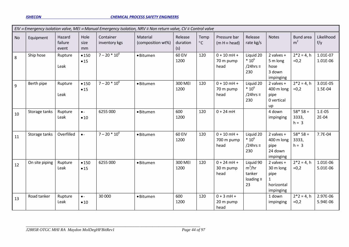
ISHECON CHEMICAL PROCESS SAFETY ENGINEERS
____________________________________________________________________________________
J2885R OTGC MHI RA Maydon MolDegHFBitRev1 Page 44 of 97
EIV Emergency isolation valve, MEI Manual Emergency Isolation, NRV ≡ Non return valve, CV ≡ Control valve
No Equipment Hazard failure event
Hole size mm
Container inventory kgs
Material (composition wt%)
Release duration (s)
Temp
C
Pressure bar
(m H head)
Release rate kg/s
Notes Bund area m2
Likelihood f/y
8 Ship hose Rupture
Leak
150
15
7 – 20 * 106 Bitumen 60 EIV
1200 120 0 + 10 mH +
70 m pump head
Liquid 20 * 106
/24hrs ≡ 230
2 valves + 5 m long hose 3 down impinging
2*2 = 4, h =0,2
1.01E-07 1.01E-06
9 Berth pipe Rupture
Leak
150
15
7 – 20 * 106 Bitumen 300 MEI
1200 120 0 + 10 mH +
70 m pump head
Liquid 20 * 106
/24hrs ≡ 230
2 valves + 400 m long pipe 0 vertical up
2*2 = 4, h =0,2
3.01E-05 1.5E-04
10 Storage tanks Rupture
Leak -
10
6255 000 Bitumen 600
1200 120 0 + 24 mH 4 down
impinging 58* 58 = 3333, h = 3
1.E-05 2E-04
11 Storage tanks Overfilled - 7 – 20 * 106
Bitumen 60 EIV 1200
120 0 + 10 mH + 700 m pump head
Liquid 20 * 106
/24hrs ≡ 230
2 valves + 400 m long pipe 24 down impinging
58* 58 = 3333, h = 3
7.7E-04
12 On site piping Rupture
Leak 150
15
6255 000 Bitumen 300 MEI 1200
120 0 + 24 mH + 30 m pump head
Liquid 90 m3/hr tanker loading ≡ 23
2 valves + 30 m long pipe 1 horizontal impinging
2*2 = 4, h =0,2
1.01E-06 5.01E-06
13 Road tanker Rupture
Leak -
10
30 000 Bitumen 600 1200
120 0 + 3 mH + 20 m pump head
1 down impinging
2*2 = 4, h =0,2
2.97E-06 5.94E-06

ISHECON CHEMICAL PROCESS SAFETY ENGINEERS
____________________________________________________________________________________
J2885R OTGC MHI RA Maydon MolDegHFBitRev1 Page 45 of 97
A-Table 3– OTGC ship bitumen offloading, storage and road tanker filling
EIV Emergency isolation valve, MEI Manual Emergency Isolation, NRV ≡ Non return valve, CV ≡ Control valve
No Equipment Hazard failure event
Hole size mm
Container inventory kgs
Material (composition wt%)
Release duration (s)
Temp
C
Pressure bar
(m H head)
Release rate kg/s
Notes Bund area m2
Likelihood f/y
14 Road tanker Overfilled 100 10 000 000
(largest) Bitumen 60 EIV
1200 120 0 + 24 mH +
20 m pump head
Liquid 90 m3/hr tanker loading ≡ 23
2 valves + NRV + 30 m long pipe 3 down impinging
2*2 = 4, h =0,2
1.01E-07

ISHECON CHEMICAL PROCESS SAFETY ENGINEERS
____________________________________________________________________________________
J2885R OTGC MHI RA Maydon MolDegHFBitRev1 Page 46 of 97
APPENDIX 6 COMPETENCIES OF RISK ASSESSORS
APPROVED INSPECTION AUTHORITY CERTIFICATE

ISHECON CHEMICAL PROCESS SAFETY ENGINEERS
____________________________________________________________________________________
J2885R OTGC MHI RA Maydon MolDegHFBitRev1 Page 47 of 97

ISHECON CHEMICAL PROCESS SAFETY ENGINEERS
____________________________________________________________________________________
J2885R OTGC MHI RA Maydon MolDegHFBitRev1 Page 48 of 97
APPENDIX 7 EMERGENCY PLAN
SITE EMERGENCY PLAN
AND
PROCEDURES

Title: Emergency Preparedness & Response
DOCUMENT NUMBER PROC.SHEQ-001 REVISION 0
EFFECTIVE DATE Jul 2019 REVIEW DATE Jul 2022
DOCUMENT CONTROLLER Mr/s ABC SHEQ Manager / Officer DOCUMENT OWNER Mr/s ABC Operations Manager

DOCUMENT NUMBER PROC.SHEQ-001 REVISION 0
EFFECTIVE DATE Jul 2019 REVIEW DATE Jul 2022
DOCUMENT CONTROLLER
Alyssa Singh DOCUMENT OWNER Linda Christie
Approver: Linda Christie Oiltanking GC - Durban
Page 2 of 57
APPROVAL PAGE
COMPIILED BY: DESIGNATION: OTGC SHEQ MANAGER
DATE: SIGNATURE:
APPROVED BY: DESIGNATION: OTGC OPERATIONS MANAGER
DATE: SIGNATURE:
AKNOWLEDGEMENT OF RECEIPT
SIGN OFF BY: DESIGNATION:
DATE: SIGNATURE:
LOCAL EMERGENCY SERVICES (FIRE CHIEF)
WITNESSES
NAME: DESIGNATION:
DATE: SIGNATURE:
NAME: DESIGNATION:
DATE: SIGNATURE:

DOCUMENT NUMBER PROC.SHEQ-001 REVISION 0
EFFECTIVE DATE Jul 2019 REVIEW DATE Jul 2022
DOCUMENT CONTROLLER
Alyssa Singh DOCUMENT OWNER Linda Christie
Approver: Linda Christie Oiltanking GC - Durban
Page 3 of 57
INTRODUCTION
The objective of the development of emergency plans is planning for the protection of people,
the environment and property.
The purpose of the emergency plan is:
a) Serve as a guideline for the handling of any emergency within the Oiltanking GC in Durban
Harbour.
b) Promote preplanning and awareness for emergencies i.e. establish response procedures
to be followed during specific types of emergencies.
c) address incidents that may occur relatively frequent (for example, uncontrolled events
which could lead to a major incident or smaller-scale major incident) but should also
include extremely rare events with serious consequences.
d) provide a structure that is able to respond to any emergency at the establishment in a
way that leads to the most effective outcome (Prevent or minimize harm and loss of
human life, equipment, plants and infrastructure.)
e) Minimize the environmental impact of emergencies that may occur on the Oiltanking site.

DOCUMENT NUMBER PROC.SHEQ-001 REVISION 0
EFFECTIVE DATE Jul 2019 REVIEW DATE Jul 2022
DOCUMENT CONTROLLER
Alyssa Singh DOCUMENT OWNER Linda Christie
Approver: Linda Christie Oiltanking GC - Durban
Page 4 of 57
Table of Contents APPROVAL PAGE ........................................................................................................................................................ 2
INTRODUCTION .......................................................................................................................................................... 3
1 SCOPE ................................................................................................................................................................. 6
2 REFERENCES ........................................................................................................................................................ 6
3 TERMS AND DEFINITIONS ................................................................................................................................... 7
4 FACILITY DESRIPTIONS ........................................................................................................................................ 8
5 RISK MANAGEMENT ........................................................................................................................................... 9
5.1 HAZARD IDENTIFICATION ....................................................................................................................................................... 9
5.2 ACTIVITIES AND EMERGENCY TYPE ..................................................................................................................................... 9
6 ACCOUNTABILITY ...............................................................................................................................................11
7 ROLES AND RESPONSIBILITIES ............................................................................................................................12
7.1 SMC (and nominated Deputy SMC) ......................................................................................................................................... 12
7.2 Emergency Coordinator ........................................................................................................................................................... 12
7.3 Operations Section Coordinator ............................................................................................................................................... 12
7.4 SIC .......................................................................................................................................................................................... 12
7.5 Planning Section Coordinator ................................................................................................................................................... 12
7.6 Situation Unit ........................................................................................................................................................................... 13
7.7 HSSE ....................................................................................................................................................................................... 13
Health and Safety .............................................................................................................................................................................. 13
Medical .............................................................................................................................................................................................. 13
Environmental .................................................................................................................................................................................... 13
7.8 Logistics Section Coordinator ................................................................................................................................................... 14
7.9 Human Resources ................................................................................................................................................................... 14
7.10 Administration ..................................................................................................................................................................... 14
7.11 Procurement and Purchasing .............................................................................................................................................. 15
7.12 Transportation ..................................................................................................................................................................... 15
7.13 Communications & IT .......................................................................................................................................................... 15
7.14 The Operations Section Coordinator ................................................................................................................................... 16
The Operation Section Coordinator will work closely with Planning and Logistics to ensure that there is no duplication or clash of interest in managing the response and ensuring that resources are effectively used. ......................................................................... 16
8 EMERGENCY PROCEDURES .................................................................................................................................17
8.1 FIRE AND EXPLOSIONS ........................................................................................................................................................ 17
8.1.1 Admin building ............................................................................................................................. 17
8.1.2 Terminal building ......................................................................................................................... 17
8.1.3 Truck depot building .................................................................................................................... 18
8.1.4 Security personnel (after hours) .................................................................................................. 18
8.1.5 General Fire ................................................................................................................................. 18
8.2 LOSS OF PRODUCT CONTAINMENT (ENVIRONMENTAL) .................................................................................................. 18
8.2.1 Terminal (Leak on Tanks/ overfilling)........................................................................................... 19
8.2.2 Security ........................................................................................................................................ 19
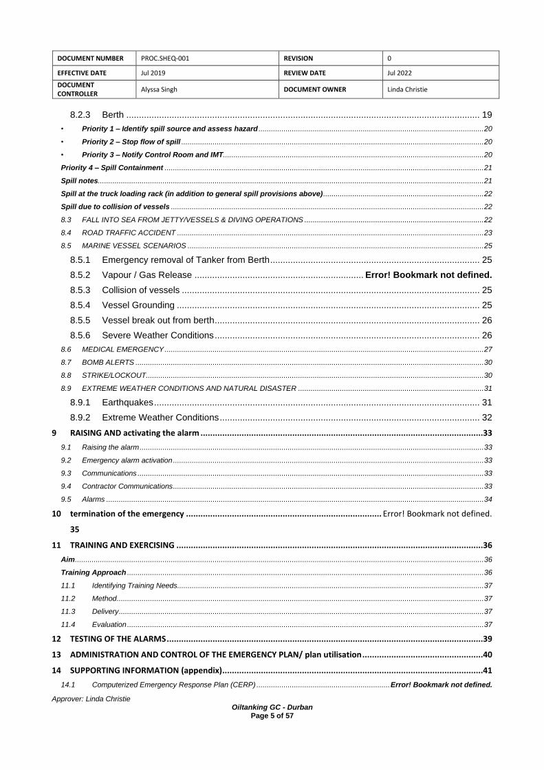
DOCUMENT NUMBER PROC.SHEQ-001 REVISION 0
EFFECTIVE DATE Jul 2019 REVIEW DATE Jul 2022
DOCUMENT CONTROLLER
Alyssa Singh DOCUMENT OWNER Linda Christie
Approver: Linda Christie Oiltanking GC - Durban
Page 5 of 57
8.2.3 Berth ............................................................................................................................................ 19
• Priority 1 – Identify spill source and assess hazard ............................................................................................................ 20
• Priority 2 – Stop flow of spill ................................................................................................................................................. 20
• Priority 3 – Notify Control Room and IMT ............................................................................................................................. 20
Priority 4 – Spill Containment ......................................................................................................................................................... 21
Spill notes ......................................................................................................................................................................................... 21
Spill at the truck loading rack (in addition to general spill provisions above) ............................................................................. 22
Spill due to collision of vessels ...................................................................................................................................................... 22
8.3 FALL INTO SEA FROM JETTY/VESSELS & DIVING OPERATIONS ...................................................................................... 22
8.4 ROAD TRAFFIC ACCIDENT ................................................................................................................................................... 23
8.5 MARINE VESSEL SCENARIOS .............................................................................................................................................. 25
8.5.1 Emergency removal of Tanker from Berth ................................................................................... 25
8.5.2 Vapour / Gas Release ................................................................... Error! Bookmark not defined.
8.5.3 Collision of vessels ...................................................................................................................... 25
8.5.4 Vessel Grounding ........................................................................................................................ 25
8.5.5 Vessel break out from berth ......................................................................................................... 26
8.5.6 Severe Weather Conditions ......................................................................................................... 26
8.6 MEDICAL EMERGENCY ......................................................................................................................................................... 27
8.7 BOMB ALERTS ....................................................................................................................................................................... 30
8.8 STRIKE/LOCKOUT .................................................................................................................................................................. 30
8.9 EXTREME WEATHER CONDITIONS AND NATURAL DISASTER ......................................................................................... 31
8.9.1 Earthquakes ................................................................................................................................. 31
8.9.2 Extreme Weather Conditions ....................................................................................................... 32
9 RAISING AND activating the alarm .....................................................................................................................33
9.1 Raising the alarm ..................................................................................................................................................................... 33
9.2 Emergency alarm activation ..................................................................................................................................................... 33
9.3 Communications ...................................................................................................................................................................... 33
9.4 Contractor Communications ..................................................................................................................................................... 33
9.5 Alarms ..................................................................................................................................................................................... 34
10 termination of the emergency ................................................................................. Error! Bookmark not defined.
35
11 TRAINING AND EXERCISING ...............................................................................................................................36
Aim .................................................................................................................................................................................................... 36
Training Approach ........................................................................................................................................................................... 36
11.1 Identifying Training Needs ................................................................................................................................................... 37
11.2 Method ................................................................................................................................................................................ 37
11.3 Delivery ............................................................................................................................................................................... 37
11.4 Evaluation ........................................................................................................................................................................... 37
12 TESTING OF THE ALARMS ...................................................................................................................................39
13 ADMINISTRATION AND CONTROL OF THE EMERGENCY PLAN/ plan utilisation ..................................................40
14 SUPPORTING INFORMATION (appendix)............................................................................................................41
14.1 Computerized Emergency Response Plan (CERP) ................................................................ Error! Bookmark not defined.

DOCUMENT NUMBER PROC.SHEQ-001 REVISION 0
EFFECTIVE DATE Jul 2019 REVIEW DATE Jul 2022
DOCUMENT CONTROLLER
Alyssa Singh DOCUMENT OWNER Linda Christie
Approver: Linda Christie Oiltanking GC - Durban
Page 6 of 57
14.2 Incident Notification Chain ................................................................................................................................................... 42
14.3 Activation of SMS/General Manager ................................................................................................................................... 43
14.4 Activation of Incident Management Team Procedure .......................................................................................................... 44
14.5 Activation of Incident Management Centre Procedure ......................................................................................................... 45
14.6 Night Shift Call Out Crisis Escalation Matrix ........................................................................................................................ 46
14.7 External Emergency Procedure (TNPA) .............................................................................................................................. 47
15 CONTACT DETAILS OILTANKING GC AND NEIGHBOURS ......................................................................................53
16 SUPPORTING DRAWINGS ...................................................................................................................................54
16.1 Site layout drawing showing the location of emergency equipment. .................................................................................... 55
16.2 Site layout drawing showing key facilities ............................................................................................................................ 57
1 SCOPE
Oiltanking GC (PTY) Ltd (hereinafter referred to as “OTGC”) in Durban import mono-ethylene
glycol (MEG), di-ethylene glycol (DEG) and molasses via ship. These materials are stored in a
tank farm in the Maydon Wharf harbour and are dispatched in road tankers to customers in the
surrounding areas.
The ERP addresses response to those emergency situations under reasonable control of the
OTGC.
Evacuation procedures and other defensive protocols are included to respond to emergencies
beyond OTGC control (e.g. fires, natural disasters, explosions, bomb or other human induced
threats, hazardous material releases, and utility failures). The plan covers all OTGC employee’s
contractor employees based at the Oiltanking Grindrod Calulo Facility (OTGC), located in the
Maydon Wharf. Additionally, JV Partners, sub-contractors, visitors, drivers, and any other third
parties are subject to provisions contained herein.
This document is intended to provide for the safety of certain third parties at work locations
during an emergency situation.
Specific emergency response arrangements must be defined and incorporated into the activity
plans for any activities not covered by the procedures in this plan.
2 REFERENCES
The following referenced documents, in whole or in part, are referenced in this document and are indispensable for its application. SANS 1514, Major hazard installation – Emergency Response Planning. SANS 10234, Global Harmonized System of classification and labelling of chemicals (GHS).

DOCUMENT NUMBER PROC.SHEQ-001 REVISION 0
EFFECTIVE DATE Jul 2019 REVIEW DATE Jul 2022
DOCUMENT CONTROLLER
Alyssa Singh DOCUMENT OWNER Linda Christie
Approver: Linda Christie Oiltanking GC - Durban
Page 7 of 57
3 TERMS AND DEFINITIONS
ACRONYM (ABBREVIATION) TERM
OTGC Oiltanking Grindrod Calulo
SMC Site Main Controller
SIC Site Incident Controller
SI Situation Unit
RT Response Team
CERT Company Emergency Response Team
ESD Emergency Shutdown
ICS Incident Command System
IPP In-Place Protection
PPE Personal Protective Equipment
EP Emergency Preparedness
ERE Emergency Response Equipment
ESD Emergency Shutdown
RA Risk Assessment
PEFDs Process Engineering Flow Diagrams
UPS Uninterruptible Power Supply
ECC Emergency Command Centre
ECO Emergency Control Officer (Command Centre)
EIO Emergency Incident Officer (Forward Control Point)
EPR Emergency Preparedness and Response plan (i.e. this document)
ERT Emergency Response Team (OTGC trained staff)
MSDS Material Safety Data Sheet
OHS Act Occupational Health and Safety Act
SHE Safety, Health and Environment
TIB Terminal Information Booklet
CERP Computerized Emergency Response Plan
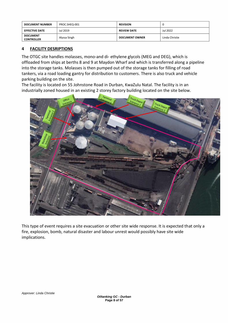
DOCUMENT NUMBER PROC.SHEQ-001 REVISION 0
EFFECTIVE DATE Jul 2019 REVIEW DATE Jul 2022
DOCUMENT CONTROLLER
Alyssa Singh DOCUMENT OWNER Linda Christie
Approver: Linda Christie Oiltanking GC - Durban
Page 8 of 57
4 FACILITY DESRIPTIONS
The OTGC site handles molasses, mono-and di- ethylene glycols (MEG and DEG), which is offloaded from ships at berths 8 and 9 at Maydon Wharf and which is transferred along a pipeline into the storage tanks. Molasses is then pumped out of the storage tanks for filling of road tankers, via a road loading gantry for distribution to customers. There is also truck and vehicle parking building on the site. The facility is located on 55 Johnstone Road in Durban, KwaZulu Natal. The facility is in an industrially zoned housed in an existing 2 storey factory building located on the site below.
This type of event requires a site evacuation or other site wide response. It is expected that only a fire, explosion, bomb, natural disaster and labour unrest would possibly have site wide implications.

DOCUMENT NUMBER PROC.SHEQ-001 REVISION 0
EFFECTIVE DATE Jul 2019 REVIEW DATE Jul 2022
DOCUMENT CONTROLLER
Alyssa Singh DOCUMENT OWNER Linda Christie
Approver: Linda Christie Oiltanking GC - Durban
Page 9 of 57
5 RISK MANAGEMENT
5.1 HAZARD IDENTIFICATION
The Facility has a capacity in excess of 37067 cubic meters and caters the storage of Molasses
and Glycols.
There is a total of 7 tanks and all tanks are Class 3B, fixed roof of which three are wooden roof
structure
The jetty consists of 2 berths and these were situated on a flat quay. The quay, fenders and the
mooring bollards are the responsibility of the Transnet Port Authorities (TNPA). Both berths are
able to handle ocean going vessels with a maximum length of 190m, maximum draught of 10m
and a maximum deadweight of 125,000 tons.
Product is imported by ship, road tanker and exported by ship, road. The facility handled
approximately 13 ships per year and 14000 road tanker trips.
The hazards associated with the storage of DEG and MEG pose a low risk and acceptable risk.
CAS
number
SANS10234
Classification
Total Maximum
Inventory (m3)
Glycol 1171 Class 3
Flammable liquids
37067
Molasses Non flammable
5.2 ACTIVITIES AND EMERGENCY TYPE
PROCESS AREA ACTIVITY TYPES OF EMERGENCIES
Tank farm Delivery/offloading
and storage of
glycol.
Filling of tanks.
Traffic accident.
Chemical spill.
Personnel exposure – thermal burns.
Fire or confined explosion.
Fire on the glycol tanks.
Tank farm Delivery/offloading
and storage of
molasses.
Filling of tanks.
Traffic accident.
Molasses spill.
Berths 8 and 9
ship offloading
Offloading hose
leaks
Environmental pollution of the bay
area.

DOCUMENT NUMBER PROC.SHEQ-001 REVISION 0
EFFECTIVE DATE Jul 2019 REVIEW DATE Jul 2022
DOCUMENT CONTROLLER
Alyssa Singh DOCUMENT OWNER Linda Christie
Approver: Linda Christie Oiltanking GC - Durban
Page 10 of 57
PROCESS AREA ACTIVITY TYPES OF EMERGENCIES
Berth pipe leaks.
Molasses, MEG
and DEG pump
house
Pumping of
materials.
Traffic accident.
Pump house fire.
Dispatch i.e. road
tanker loading
Loading onto
trucks.
Spillages from loading hoses.
Admin, Offices
and parking area
Spillages of
molasses.
Messy working area.
Environmental pollution.
Truck
maintenance
workshop
Servicing and
repair of truck and
road tankers e.g.
changing of oil,
welding, grinding,
drilling
Fire in the workshop due to spillage of
fuels
Environmental pollution due to fuel spills
General Anywhere on site Medical emergency.
Bomb or external threat.
Labour unrest.

DOCUMENT NUMBER PROC.SHEQ-001 REVISION 0
EFFECTIVE DATE Jul 2019 REVIEW DATE Jul 2022
DOCUMENT CONTROLLER
Alyssa Singh DOCUMENT OWNER Linda Christie
Approver: Linda Christie Oiltanking GC - Durban
Page 11 of 57
6 ACCOUNTABILITY
All Staff & Contractors
Duty Operations Supervisor
Duty Operations Supervisor
Contacts
Duty Incident Management Team
SMS
contacts
Emergency Services
and
Stakeholders as required
HSSE Manager
SMS
Incident
Alarm sounds
Staff alerted
Activation Duty IMT go to
Incident Management Centre/Ops Room
(Section 2)
Manual Activation Operations (Section 2)
Activation of IMT (Section 4)
Notification of Emergency Services and other
Stakeholders as required (Section 4)
Activation of linked plans (Section 5)
Specific Procedures (Section 6)
Developed solutions
Notify HSSE Manager
Manage issues Monitor
If in doubt escalate response
Is it a recordable
Injury?
Escalate response?
YES
YES
NO
NO

DOCUMENT NUMBER PROC.SHEQ-001 REVISION 0
EFFECTIVE DATE Jul 2019 REVIEW DATE Jul 2022
DOCUMENT CONTROLLER
Alyssa Singh DOCUMENT OWNER Linda Christie
Approver: Linda Christie Oiltanking GC - Durban
Page 12 of 57
7 ROLES AND RESPONSIBILITIES
7.1 SMC (and nominated Deputy SMC)
The SMC, normally the Terminal Manager, is responsible for the overall management of the incident response, for delegation of Incident Management Team roles, and for management of related issues that arise.
7.2 Emergency Coordinator
Assisting the SMC and SIC in managing the overall response. Briefing the Core Team representatives on their roles and responsibilities within the response. Managing the day to day support activities of the team for the SMC.
7.3 Operations Section Coordinator
On notification of an incident a SIC should be nominated locally or a qualified staff member should be sent to the incident site. The Operations Section Coordinator is the focal point for all operational activities associated with the response. The Coordinator will use the appropriate operational plan associated with the incident and ensure that the SIC is fully supported.
7.4 SIC
The SIC directs the overall local/site response to the incident. The SIC will be dispatched immediately to the site, if not already there, and will remain at the scene throughout the incident, or until relieved. The SIC reports to the SMC through the Operations Section Coordinator. SICs will be familiar with the emergency plans and the role that will be expected of them in managing/supporting any site response. Key responsibilities include:
• Overall responsibility on site for the operational response
• Focal point on site for the local authorities involved in the response
• Management of the RT
• Working with the SMC in identifying the key issues, objectives and strategies for the response
• Review key issues on an on-going basis throughout the operation
7.5 Planning Section Coordinator
This function will initially be covered by the senior HSSE representative who may also function in parallel as the Emergency Coordinator. The Planning Section Coordinator is responsible for ensuring that the operation is effectively supported, providing expert advice to the team on actions necessary to ensure that HSSE issues are covered and incorporated in to the operational response. The Situation Unit is also positioned in this Section and it is here that all the information on the response is managed.

DOCUMENT NUMBER PROC.SHEQ-001 REVISION 0
EFFECTIVE DATE Jul 2019 REVIEW DATE Jul 2022
DOCUMENT CONTROLLER
Alyssa Singh DOCUMENT OWNER Linda Christie
Approver: Linda Christie Oiltanking GC - Durban
Page 13 of 57
The Planning Section Coordinator will work closely with the Emergency Coordinator to ensure that all functions within this Section are covered.
7.6 Situation Unit
This function is vital to ensuring that information is captured and distributed to the SIC, Incident Management Team, JV Partners, and to any others involved. It helps to reduce confusion and duplication of effort. It is important that the post-holder has a clear understanding of the operation. For a major incident a Senior Manager should be appointed to head this Unit. The Situation Unit is responsible for the collection and organisation of incident status and situation information, and the evaluation, analysis and display of that information. Primary responsibilities include:
• Preparation of standard and special maps for planning and recording incident operations.
• Collection of data from all team members and summarise into concise briefing reports.
• Maintaining status boards in the Incident Management Centre to accurately display the current status of the response activities.
• Preparation and communication of Situation Reports to all other pertinent locations.
7.7 HSSE
Health and Safety
Ensuring that considerations are taken into account in the planning and operational aspects of the response. Occupational health issues should also be considered and include: Establishment of protective procedures and clothing requirements for the operation. Conduct monitoring/surveillance of working areas. Identifying all health hazards associated with the incident.
Medical
Co-ordinate/provide on-site medical care to affected personnel when such services are required. Notify appropriate agencies of all medical/health related incidents.
Environmental
Provision of expert advice to the Incident Management Team on actions necessary to minimise the environmental effects of the include: Establishment of an Environmental Surveillance Programme. Conducting spill or release forecasting. Identifying response priorities based upon environmental sensitivities. Securing all appropriate permits and approvals from the appropriate authorities. Implementation of a programme to protect and rehabilitate wildlife. Oversee the disposal of wastes generated by response action. Recommendation of final "clean-up" standards.
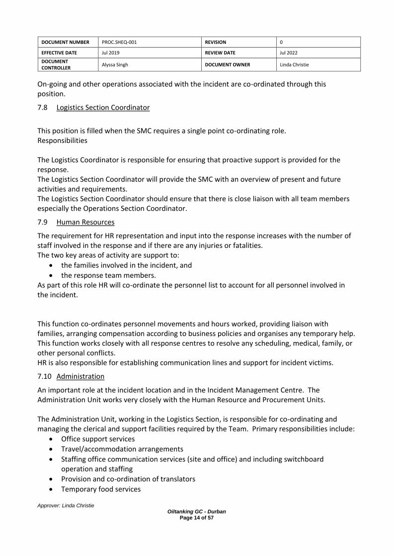
DOCUMENT NUMBER PROC.SHEQ-001 REVISION 0
EFFECTIVE DATE Jul 2019 REVIEW DATE Jul 2022
DOCUMENT CONTROLLER
Alyssa Singh DOCUMENT OWNER Linda Christie
Approver: Linda Christie Oiltanking GC - Durban
Page 14 of 57
On-going and other operations associated with the incident are co-ordinated through this position.
7.8 Logistics Section Coordinator
This position is filled when the SMC requires a single point co-ordinating role. Responsibilities The Logistics Coordinator is responsible for ensuring that proactive support is provided for the response. The Logistics Section Coordinator will provide the SMC with an overview of present and future activities and requirements. The Logistics Section Coordinator should ensure that there is close liaison with all team members especially the Operations Section Coordinator.
7.9 Human Resources
The requirement for HR representation and input into the response increases with the number of staff involved in the response and if there are any injuries or fatalities. The two key areas of activity are support to:
• the families involved in the incident, and
• the response team members. As part of this role HR will co-ordinate the personnel list to account for all personnel involved in the incident. This function co-ordinates personnel movements and hours worked, providing liaison with families, arranging compensation according to business policies and organises any temporary help. This function works closely with all response centres to resolve any scheduling, medical, family, or other personal conflicts. HR is also responsible for establishing communication lines and support for incident victims.
7.10 Administration
An important role at the incident location and in the Incident Management Centre. The Administration Unit works very closely with the Human Resource and Procurement Units. The Administration Unit, working in the Logistics Section, is responsible for co-ordinating and managing the clerical and support facilities required by the Team. Primary responsibilities include:
• Office support services
• Travel/accommodation arrangements
• Staffing office communication services (site and office) and including switchboard operation and staffing
• Provision and co-ordination of translators
• Temporary food services

DOCUMENT NUMBER PROC.SHEQ-001 REVISION 0
EFFECTIVE DATE Jul 2019 REVIEW DATE Jul 2022
DOCUMENT CONTROLLER
Alyssa Singh DOCUMENT OWNER Linda Christie
Approver: Linda Christie Oiltanking GC - Durban
Page 15 of 57
7.11 Procurement and Purchasing
To help reduce confusion and double ordering, all purchases should be focused through the Procurement Unit. Some local representation might be needed on site; however, additional support staff will in general be more effective working from their normal environment. The Procurement Unit co-ordinates the purchasing of all equipment, supplies, and services for the response. This function should establish formal purchase order procedures and arrange for all contractors, vehicles, boats, aircraft and office facilities needed for an emergency and for the transportation to site. They should maintain records and controls on all procurement activities working closely with the Transportation Unit and the Accounting Unit. As the response develops there may be several support operations taking place e.g. fire-fighting operations, spill control - all will be co-ordinated through this Section.
7.12 Transportation
The Transportation Unit works very closely with the Procurement Unit and Operations Section. For smaller incidents the purchasing and transportation requirements may well be handled by the same team member. In larger incidents representatives may be required to co-ordinate activities. The Transportation Unit arranges for the physical movement of equipment and materials to the incident site. On-site warehousing and local distribution are co-ordinated by this Unit working with Procurement and Operations. In a non-transportation event, provide logistical support in the movement of people, equipment, and materials to the incident site. Establish a warehousing and distribution system. Ensure that all team members understand the role and services being managed by the Transportation Unit.
7.13 Communications & IT
Good communications are the heart of a successful operation. It is vital that they are established as quickly as possible. In nearly all circumstances additional assistance will be needed at the incident site. Additional support should be provided as quickly as possible. A separate support document, “IT and Telecommunications Disaster Recovery Plan”, will be used in conjunction with this Plan in the event that the major incident is itself a total loss of IT and telecomms.

DOCUMENT NUMBER PROC.SHEQ-001 REVISION 0
EFFECTIVE DATE Jul 2019 REVIEW DATE Jul 2022
DOCUMENT CONTROLLER
Alyssa Singh DOCUMENT OWNER Linda Christie
Approver: Linda Christie Oiltanking GC - Durban
Page 16 of 57
The Communications & IT Unit must ensure that effective communication between the Incident Management Centre and other key locations. This Unit is responsible for co-ordinating all communication services and equipment, multi-location conference calls, radios, cellular phones etc. This Unit provides back-up equipment facilities for the incident sites.
7.14 The Operations Section Coordinator
The Operation Section Coordinator will work closely with Planning and Logistics to ensure that there is no duplication or clash of interest in managing the response and ensuring that resources are effectively used.
Roles and Responsibilities
SMC Terminal Manager Linda Christie
Emergency Coordinator HSSE Manager Alyssa Singh
Operations Section Coordinator Operations Manager Desigan Naidoo
SIC Site Supervisor Reagan Naidoo
Planning Section Coordinator Transport Manager Sunil Aungadh
Logistics Coordinator Logistics Abel Marimuthu / Roslyn Erasmus
Communication & IT IT Manager Kavir Baldeo
Finance Financial Manager Navitha Roy

DOCUMENT NUMBER PROC.SHEQ-001 REVISION 0
EFFECTIVE DATE Jul 2019 REVIEW DATE Jul 2022
DOCUMENT CONTROLLER
Alyssa Singh DOCUMENT OWNER Linda Christie
Approver: Linda Christie Oiltanking GC - Durban
Page 17 of 57
8 EMERGENCY PROCEDURES
The hazards on the site include incidents that can significantly impact on people, property and the
environment.
The types of emergencies include but not limited to: -
a) fire: jet, pool and tank,
b) spillages,
c) environmental pollution,
d) heat radiation
e) lightning strike
f) road accident
g) medical emergency
8.1 FIRE AND EXPLOSIONS
These could include molasses, MEG and DEG fires. There are various types of smoke and heat detectors on the OTGC site that will alert and trigger
alarms in case of fires.
Refer to document by TECHNO SWITCH FIRE DETECTION: SMOKE & HEAT DETECTORS SERIES 65
8.1.1 Admin building
• Stop all activities in a safe manner • Trigger the nearest emergency alarm button • If possible, fight the fire with portable fire extinguishers • Evacuate the building
• Proceed to the assembly point
• @ gate 1 or 2 (depending on the wind direction) • Follow the TNPA Fire call out procedure (14.7)
8.1.2 Terminal building
• Stop all activities in a safe manner • Trigger the nearest emergency alarm button • Rescue injured and endangered persons, if safe to do so • If possible, fight the fire with portable fire extinguishers • Inform the control room about WHERE WHAT happened and WHO is informing them with the terminal radio
• Proceed to the assembly point outside
• @ gate 1 or 2 (depending on the wind direction)
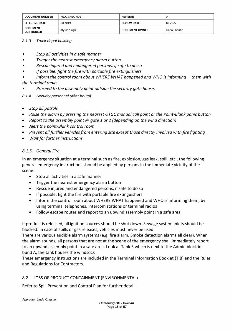
DOCUMENT NUMBER PROC.SHEQ-001 REVISION 0
EFFECTIVE DATE Jul 2019 REVIEW DATE Jul 2022
DOCUMENT CONTROLLER
Alyssa Singh DOCUMENT OWNER Linda Christie
Approver: Linda Christie Oiltanking GC - Durban
Page 18 of 57
8.1.3 Truck depot building
• Stop all activities in a safe manner • Trigger the nearest emergency alarm button • Rescue injured and endangered persons, if safe to do so • If possible, fight the fire with portable fire extinguishers • Inform the control room about WHERE WHAT happened and WHO is informing them with the terminal radio • Proceed to the assembly point outside the security gate house.
8.1.4 Security personnel (after hours)
• Stop all patrols
• Raise the alarm by pressing the nearest OTGC manual call point or the Point-Blank panic button
• Report to the assembly point @ gate 1 or 2 (depending on the wind direction)
• Alert the point-Blank control room
• Prevent all further vehicles from entering site except those directly involved with fire fighting
• Wait for further instructions
8.1.5 General Fire
In an emergency situation at a terminal such as fire, explosion, gas leak, spill, etc., the following general emergency instructions should be applied by persons in the immediate vicinity of the scene:
• Stop all activities in a safe manner
• Trigger the nearest emergency alarm button
• Rescue injured and endangered persons, if safe to do so
• If possible, fight the fire with portable fire extinguishers
• Inform the control room about WHERE WHAT happened and WHO is informing them, by using terminal telephones, intercom stations or terminal radios
• Follow escape routes and report to an upwind assembly point in a safe area If product is released, all ignition sources should be shut down. Sewage system inlets should be blocked. In case of spills or gas releases, vehicles must never be used. There are various audible alarm systems (e.g. fire alarm, Smoke detection alarms all clear). When the alarm sounds, all persons that are not at the scene of the emergency shall immediately report to an upwind assembly point in a safe area. Look at Tank 5 which is next to the Admin block in bund A, the tank houses the windsock These emergency instructions are included in the Terminal Information Booklet (TIB) and the Rules and Regulations for Contractors.
8.2 LOSS OF PRODUCT CONTAINMENT (ENVIRONMENTAL)
Refer to Spill Prevention and Control Plan for further detail.

DOCUMENT NUMBER PROC.SHEQ-001 REVISION 0
EFFECTIVE DATE Jul 2019 REVIEW DATE Jul 2022
DOCUMENT CONTROLLER
Alyssa Singh DOCUMENT OWNER Linda Christie
Approver: Linda Christie Oiltanking GC - Durban
Page 19 of 57
8.2.1 Terminal (Leak on Tanks/ overfilling)
The tanks are fitted with high level alarms. The automated high-level switches will prevent overfill scenario on the tanks in the event that action could not be taken when an overfill alarm went off. Refer to OTGC Memo dated 11/09/2007, Revised 15/12/ 2010 By Lo Vanhaelen, revised Manfred Niemann
Also refer to the OTGC Tank Overfill Protection Standard Rev 0 Approved by Rob Eijkholt : General Manager Operations Excellence & Compliance, 20/11/2016 If these systems fail, any person that notices this should: -
• Locate the tank, source of release
• Assess if you can safely reach the tank isolation (taking into consideration the duration) • Close the valve
• Stop the pump
• Demarcate and block access to the tank
• Block all routes to storm water drains
• Inform the terminal manager • Recover with a pump back into the tank
8.2.2 Security
In the event of a spill during loading or offloading of material from the road tankers
• Stop all patrols
• Raise the alarm by pressing the nearest OTGC manual call point or the Point-Blank panic button
• Report to the assembly point @ gate 1 or 2
• Alert the point-Blank control room and OTGC personnel
• Use spill boom from the spill kits located on site to contain the spill, put booms around the drains
• Do not attempt to clean up a spill if not trained to do so.
8.2.3 Berth
Leak on Pipelines
• Immediately stop the offloading and close all valves to prevent the spillage from entering the sea
• Place sand bags around the spill
• Contact the SIC at operations control room via the portable radio

DOCUMENT NUMBER PROC.SHEQ-001 REVISION 0
EFFECTIVE DATE Jul 2019 REVIEW DATE Jul 2022
DOCUMENT CONTROLLER
Alyssa Singh DOCUMENT OWNER Linda Christie
Approver: Linda Christie Oiltanking GC - Durban
Page 20 of 57
• Cordon off the spill area and restrict access of persons and vehicles
• Spill at Berths 8 and 9 Being within an open harbour, it is anticipated that the marine oil spill will have to be contained as quick as possible and treated within the harbour • Priority 1 – Identify spill source and assess hazard
• Assess source, type and extent of the spill
• Assess hazards from the spill
• Check for fire and explosion risk:
o Extinguish all ignition sources in the area
o Move machinery/vehicles if safe to do so or shut down if necessary
o Isolate all live equipment to prevent sparks
• Raise alarm and close off affected area
Contact TNPA Environmental department and advise where the spill occurred, approximate quantity released and product type
• If necessary, evacuate non-essential personnel to Emergency Assembly Area
• Stay upwind of the spill
• Activate spill response contractors as required – Drizit and OSRL
• Priority 2 – Stop flow of spill
• Ensure that any necessary safety equipment is worn
• Stop flow at source of spill – using the oil spill kits in the shipping kiosk
• Attempt to limit spread of the spill, as required
o Deploy boom stored at berths 8 and 9, with assistance from the vessel’s crew, fore and aft of the vessel to contain and assist salvage of the spilled product in between the ship and berth area
o Prevent off-site migration by surface run-off; place sorbent materials around leaking item(s), if necessary, use sorbent materials to form a runoff barrier
• Priority 3 – Notify Control Room and IMT
• Notify Control Room as soon as possible after ensuring the safety of all personnel and attempting to stop flow and limit spread.
• Notify the source, volume of spill, product involved, fire risk, casualties etc.
• Control Room to follow notification guidelines, the Operations Supervisor will contact the Duty SMC/General Manager

DOCUMENT NUMBER PROC.SHEQ-001 REVISION 0
EFFECTIVE DATE Jul 2019 REVIEW DATE Jul 2022
DOCUMENT CONTROLLER
Alyssa Singh DOCUMENT OWNER Linda Christie
Approver: Linda Christie Oiltanking GC - Durban
Page 21 of 57
• SMC/General Manager will escalate the response according to the ERP guidance e.g. mobilise spill response contractors, SIC and Response Team etc.
• Ensure the area is safe for further operations by measuring the LEL and ensuring it is 0
Priority 4 – Spill Containment
Containing spills significantly reduces the effort required to control and clean up the spill.
• For all spills, deploy absorbents to contain and soak up the spill
• Prevent spread of fuel by using booms
• It may be possible to hold the fuel in depressions by using absorbent materials, or by building small dams.
• Response operations should not be commenced in the affected area until deemed safe.
• Use proper PPE, by referring to the MSDS of the material spilled.
Priority 5 – Spill Recovery and Clean-Up
If spill has been successfully contained on-site, commence spill clean-up operations
IMT to monitor spill and co-ordinate operations
IMT to complete the incident report form and submit copies as required
• Recover as much of the spill as possible
• Where possible salvage spilled product in proper containers & pump back to system depending on quality
• If possible, use pumps to remove spill straight to containers/containment. Ensure empty drums used are of sufficiently good quality are available near the spill site
• Absorbent pads should be spread on any remaining spill that cannot be pumped or manually removed
• Spill soaked absorbents must be picked up and placed in plastic bags or empty drums
• Contaminated soils etc. can be stored in drums or skips and these should be on hard standings
• Drums containing contaminated liquids should be stored in bunded areas or on bund pallets
• Do not over fill containers with contaminated materials or liquids
• Contaminated clothing and PPE should be cleaned if lightly contaminated or if heavily contaminated treated as contaminated waste e.g. placed in plastic bags
• All wastes are to be disposed of using approved methods and by an appropriately authorised waste contractor e.g. licenced by the local authorities
Spill notes
The Health and Safety to personnel is paramount in case of a spill

DOCUMENT NUMBER PROC.SHEQ-001 REVISION 0
EFFECTIVE DATE Jul 2019 REVIEW DATE Jul 2022
DOCUMENT CONTROLLER
Alyssa Singh DOCUMENT OWNER Linda Christie
Approver: Linda Christie Oiltanking GC - Durban
Page 22 of 57
Personnel should be aware of the location and use of spill kits Spill at the truck loading rack (in addition to general spill provisions above)
• Activate ESD to stop pumping
• Close truck inlet valves to stop product flow
• Truck’s engine should not be started until the area is cleared of LEL and declared safe
• Do not allow any ignition sources in spilled area
Spill due to collision of vessels
• Stop cargo operations if affected by the collision
• Report to the Port Authority any collision incident at OTGC berths
• Activate IMT
• Call out Drizit /OSRL depending on the magnitude of the spill
• If there are personnel who have fallen into the sea, activate Emergency Response Procedure for “Personnel falling into the sea”
8.3 FALL INTO SEA FROM JETTY/VESSELS & DIVING OPERATIONS
The greatest risk to personnel working at jetties is falling into the water and be exposed to the elements and/or drowning. To limit this risk all persons working over or adjacent to water are required to wear a suitable life vest.
• Adequate lifebuoys will be positioned directly below and adjacent to each work site.
• Any person falling into the water must be examined by a Doctor prior to recommencing work.
Personnel falling into the sea
• If a person is sent to or thought to have fallen into the sea; raise alarm, inform the CCR.
• Throw the nearest life buoy to the person & help him to stay afloat. SIC SIC responsibilities shall include the following: Ensure that all personnel operating in rescue are accounted for and wearing appropriate PPE. Develop a rescue plan and a back-up plan. Ensure the plan and back-up plan, which include emergency procedures, are communicated to all personnel operating on the incident.
• The Rescue Plan Rescue operations should be conducted with as little risk to the rescuers as necessary to affect the rescue. Low-risk operations may not always be possible but should be considered first. The order of rescue from low-risk to high-risk are: TALK – if water is calm or slow moving, try to talk the victim into self-rescue if possible. REACH – extend an arm, boat hook, or any other such object to reach the victim and pull from the water.

DOCUMENT NUMBER PROC.SHEQ-001 REVISION 0
EFFECTIVE DATE Jul 2019 REVIEW DATE Jul 2022
DOCUMENT CONTROLLER
Alyssa Singh DOCUMENT OWNER Linda Christie
Approver: Linda Christie Oiltanking GC - Durban
Page 23 of 57
THROW – attempt to throw the victim(s) a throw-bag rescue line or some other type of approved safety flotation device and “pendulum-belay” or “pull” the victim(s). ROW - If it is determined that a boat-based operation shall be utilized, SIC shall assign personnel to assist are establish the recovery method with the RT before rescue is made. GO - If it is not possible to row to the victim, SIC should consider putting a rescuer or rescuers in the water to reach the victim. This is a very high-risk operation and shall be conducted as a last resort. Prior to entering the water, rescue personnel shall be briefed on the plan, the back-up plan and emergency procedures. Rescue personnel shall never be attached to a life line without the benefit of a quick-release mechanism approved for water rescue. Rescue personnel shall never do a “breath-hold” surface dive in an attempt to locate a victim beneath the surface of the water.
• Assess the Victim When the rescuers reach the victim, a primary survey shall be completed. If the victim is conscious, rescuers should determine if the victim can assist in the rescue. If the victim is unconscious, the rescue must be completed as quickly as possible.
• Treatment Initiate C-spine precautions as soon as possible. Conduct a secondary survey and correct any life-threatening conditions. Provide First Aid treatment and transportation to a hospital as indicated.
• After Rescue Ensure personnel accountability. Consider decontamination of victim(s) and rescuer(s). Recover all tools and equipment used in the rescue/recovery. In cases of a fatality, consider leaving everything in place until the investigative process has been completed. Consider a Post Incident Critique (may be more appropriate at a later date). Return to service after returning all equipment to apparatus.
• Other Considerations The effects of inclement weather and water conditions on the hazard profile, the victim(s), and the rescuers, with particular attention to the effects of pollutants. Water rescue incidents attract the news media; consider preparing a media statement.
• Diving Incidents In the case of diving accidents the crew of the diving spread will be trained in the rescue of diver in difficulty. Resuscitation will by trained first-aiders and carried out if necessary. Due to the limited depth of the water it is not considered that a hyperbaric chamber will be required. Isolate the source of the hazard before rescuing persons, e.g. trip the power supply, stop moving equipment.
8.4 ROAD TRAFFIC ACCIDENT
Guidelines

DOCUMENT NUMBER PROC.SHEQ-001 REVISION 0
EFFECTIVE DATE Jul 2019 REVIEW DATE Jul 2022
DOCUMENT CONTROLLER
Alyssa Singh DOCUMENT OWNER Linda Christie
Approver: Linda Christie Oiltanking GC - Durban
Page 24 of 57
Use defensive driving techniques at all times or ensure that driver of occupied vehicle uses these techniques Drivers involved in any accident will report to their Manager and the HSSE Department Try to save life and assist the injured with first aid. Call for medical assistance. Stay with your vehicle, unless threatened or other circumstances dictated otherwise. Keep a record of the condition and symptoms of the injured, with one person to watch over each seriously injured person if possible. At all times be aware of the further risks presented by traffic passing the scene. A crowd may gather very quickly after an accident. If crowd aggression appears a serious threat be prepared to drive on to local authorities. Accidents resulting in serious injury to employees will be dealt with by local emergency services, the HR Department will assist employees as required and update Management as required. OTGC personnel involved in traffic accidents maybe be subject to drug and alcohol tests, by the company or local authorities.
• Breakdown
• Attempt to repair the vehicle or request assistance
• Inform your Manager.
• STAY WITH YOUR VEHICLE
• Stay alert: if off site one person should always be awake.
• Keep in touch with duty manager with regular updates. • Lost Vehicle (Off Site) • Guidelines
This is similar to a breakdown. The definition is clear: you have no idea where you are, so there is no point driving in any direction, or you cannot move because there is no, or dangerously little, visibility.
• Stay with your vehicle
• Think and do not panic
• Inform Manager and call for assistance if necessary
• Stay alert: one person should always be awake
• Assess your water resources and husband them (but not too carefully)
• Keep in touch with Manager with regular updates • Actions
• Inform CMT members.
• Confirm last known position of vehicle
• Confirm time of last check-in
• Inform Local authorities and ask for assistance as required
• Maintain contact with the Local authorities
• If contact with the vehicle is resumed, ask for position and status report
• Advise them of what assistance is on its way
• Advise them of medical techniques as necessary
• Maintain frequent contact • Missing Person
Based upon the journey plan if a person is overdue at his destination by a period that is unlikely to be due to normal variations caused by traffic density.

DOCUMENT NUMBER PROC.SHEQ-001 REVISION 0
EFFECTIVE DATE Jul 2019 REVIEW DATE Jul 2022
DOCUMENT CONTROLLER
Alyssa Singh DOCUMENT OWNER Linda Christie
Approver: Linda Christie Oiltanking GC - Durban
Page 25 of 57
The SMC Terminal Manager shall be informed and the Local Authorities alerted.
8.5 MARINE VESSEL SCENARIOS
During pre-cargo meeting, vessel’s chief officer / master is instructed to inform / report to the Terminal Control Room any incident or accident that may occur in the vessel during her stay at OTGC berths. A portable radio has been provided to the vessel by the terminal, which is to be used for communicating such eventuality. Terminal Control Room shall be made aware of a marine vessel incident through the following:
• Report coming from the vessel’s crew
• Report coming from any OTGC personnel
8.5.1 Emergency removal of Tanker from Berth
When the emergency is on a tanker, it is recognized that, in the interest of the tanker, the safety of shore installation and often that of the whole port, the ship should be kept alongside whenever possible. This would improve the possibility of shore-based personnel and equipment being used to tackle an emergency on board. However, if a fire on a tanker or on a berth cannot be controlled, it may be necessary to consider whether or not the tanker should be removed from the berth. Planning for such an event may require consultation between the port authority, Fire department and master of the tanker If the incident escalates, the plan may invite consideration of removing other, presently unaffected ships from nearby or downwind berths. The plan should stress the need to avoid precipitate action that might increase, rather than decrease, the danger to the tanker, the terminal, other ships berthed nearby and other installations.
8.5.2 Collision of vessels
• Report to the Port Authority any collision incident at OTGC berths.
• Stop cargo operations, until safe to re-commence.
• If the collision resulted in shipboard fire, activate Emergency Response Procedure for Fire.
• If the collision resulted in marine oil spill, activate Emergency Response Procedure for Spills.
• If there are personnel who fell into the sea, activate Emergency Response Procedure for “Personnel falling into the sea”.
8.5.3 Vessel Grounding
Report to the Port Authority of any vessel grounding incident at Maydon wharf 8 and 9 berths If the vessel has ran aground while still about to berth, the Port Authority shall provide the necessary manpower and equipment to move the vessel.

DOCUMENT NUMBER PROC.SHEQ-001 REVISION 0
EFFECTIVE DATE Jul 2019 REVIEW DATE Jul 2022
DOCUMENT CONTROLLER
Alyssa Singh DOCUMENT OWNER Linda Christie
Approver: Linda Christie Oiltanking GC - Durban
Page 26 of 57
If the vessel was grounded because of overloading while still berthed and connected to the Terminal, pump back the overloaded product to the shore tank in order to re-float the vessel. Activate the appropriate emergency response procedure/s depending on the severity and type of incident that followed or as a result of the vessel grounding incident.
8.5.4 Vessel break out from berth
• Raise the alarm and announce thru radio the type and location of incident.
• Stop all cargo operations.
• Inform the Port Control.
• If the breakout resulted in marine oil spill, activate Emergency Response Procedure for Spill.
8.5.5 Severe Weather Conditions
Vessels are not allowed to berth or un-berth at wind speed of greater than 20 knots (subject to harbor master’s discretion) • Report to the Port Authority any collision incident at OTGC berths. • Stop cargo operations, until safe to re-commence. • If the collision resulted in shipboard fire, activate Emergency Response Procedure for Fire. • If the collision resulted in marine oil spill, activate Emergency Response Procedure for Spills. • If there are personnel who fell into the sea, activate Emergency Response Procedure for “Personnel falling into the sea”.
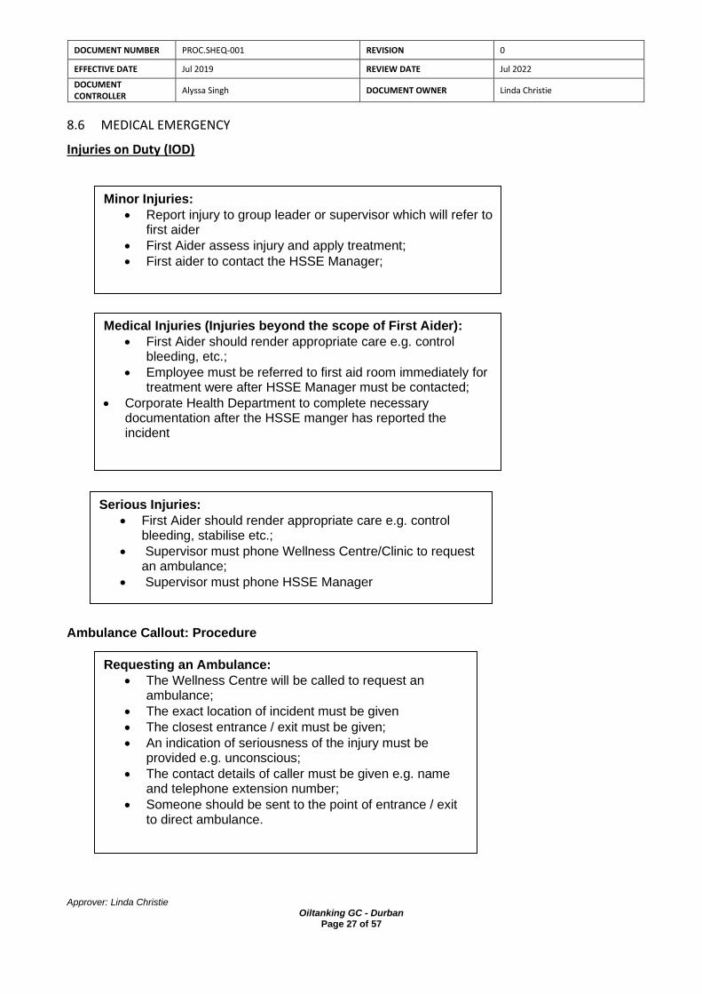
DOCUMENT NUMBER PROC.SHEQ-001 REVISION 0
EFFECTIVE DATE Jul 2019 REVIEW DATE Jul 2022
DOCUMENT CONTROLLER
Alyssa Singh DOCUMENT OWNER Linda Christie
Approver: Linda Christie Oiltanking GC - Durban
Page 27 of 57
8.6 MEDICAL EMERGENCY
Injuries on Duty (IOD) Ambulance Callout: Procedure
Minor Injuries:
• Report injury to group leader or supervisor which will refer to first aider
• First Aider assess injury and apply treatment;
• First aider to contact the HSSE Manager;
Medical Injuries (Injuries beyond the scope of First Aider):
• First Aider should render appropriate care e.g. control bleeding, etc.;
• Employee must be referred to first aid room immediately for treatment were after HSSE Manager must be contacted;
• Corporate Health Department to complete necessary documentation after the HSSE manger has reported the incident
Serious Injuries:
• First Aider should render appropriate care e.g. control bleeding, stabilise etc.;
• Supervisor must phone Wellness Centre/Clinic to request an ambulance;
• Supervisor must phone HSSE Manager
Requesting an Ambulance:
• The Wellness Centre will be called to request an ambulance;
• The exact location of incident must be given
• The closest entrance / exit must be given;
• An indication of seriousness of the injury must be provided e.g. unconscious;
• The contact details of caller must be given e.g. name and telephone extension number;
• Someone should be sent to the point of entrance / exit to direct ambulance.
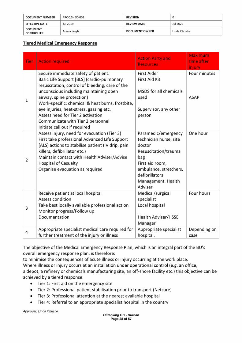
DOCUMENT NUMBER PROC.SHEQ-001 REVISION 0
EFFECTIVE DATE Jul 2019 REVIEW DATE Jul 2022
DOCUMENT CONTROLLER
Alyssa Singh DOCUMENT OWNER Linda Christie
Approver: Linda Christie Oiltanking GC - Durban
Page 28 of 57
Tiered Medical Emergency Response
Tier Action required Action Party and Resources
Maximum time after injury
1
Secure immediate safety of patient. Basic Life Support [BLS] (cardio-pulmonary resuscitation, control of bleeding, care of the unconscious including maintaining open airway, spine protection) Work-specific: chemical & heat burns, frostbite, eye injuries, heat-stress, gassing etc. Assess need for Tier 2 activation Communicate with Tier 2 personnel Initiate call out if required
First Aider First Aid Kit MSDS for all chemicals used Supervisor, any other person
Four minutes ASAP
2
Assess injury, need for evacuation (Tier 3) First take professional Advanced Life Support [ALS] actions to stabilise patient (IV drip, pain killers, defibrillator etc.) Maintain contact with Health Adviser/Advise Hospital of Casualty Organise evacuation as required
Paramedic/emergency technician nurse, site doctor Resuscitation/trauma bag First aid room, ambulance, stretchers, defibrillators Management, Health Adviser
One hour
3
Receive patient at local hospital Assess condition Take best locally available professional action Monitor progress/Follow up Documentation
Medical/surgical specialist Local hospital Health Adviser/HSSE Manager
Four hours
4 Appropriate specialist medical care required for further treatment of the injury or illness
Appropriate specialist hospital.
Depending on case
The objective of the Medical Emergency Response Plan, which is an integral part of the BU’s overall emergency response plan, is therefore: to minimise the consequences of acute illness or injury occurring at the work place. Where illness or injury occurs at an installation under operational control (e.g. an office, a depot, a refinery or chemicals manufacturing site, an off-shore facility etc.) this objective can be achieved by a tiered response:
• Tier 1: First aid on the emergency site
• Tier 2: Professional patient stabilisation prior to transport (Netcare)
• Tier 3: Professional attention at the nearest available hospital
• Tier 4: Referral to an appropriate specialist hospital in the country

DOCUMENT NUMBER PROC.SHEQ-001 REVISION 0
EFFECTIVE DATE Jul 2019 REVIEW DATE Jul 2022
DOCUMENT CONTROLLER
Alyssa Singh DOCUMENT OWNER Linda Christie
Approver: Linda Christie Oiltanking GC - Durban
Page 29 of 57
Actions
• Raise alarm.
• Activate terminal IMT based severity & number of people injured.
• Administer first-aid.
• If victim is in a serious condition and cannot be mobilised from the location, call and ambulance.
• Advise HSSE Department of all injuries or illness
• Hospital and OTGC to ensure that casualties are provided with immediate medical care in case of emergencies.
• All OTGC employees and contractors working can use the above services.
• All emergencies brought to the hospital are subject to categorization as per the existing Australian triage system and generally the hospital accepts levels 3 to 5 emergency cases.
• It will be solely on the discretion of the attending doctor if the patient needs to be shifted to any other hospital for further care.
• The ambulance team/OTGC control room should, if possible, call the hospital and inform the medical condition prior to evacuating the casualty (ies) to the hospital.
• Where possible, a responsible company employee will accompany the patient to the hospital and a valid ID of the patient needs to be provided to the hospital.
• In emergency cases, a verbal approval from OTGC’s representative is acceptable to the hospital, but a confirmation by e-mail/referral form from General Manager or HSSE Manager within 24 hours of admission of the patient is required.
Medical Contact Details
ER24 Ambulance
Sister Bhengu Nurse 083 428 4794
St Augustine’s Hospital
OTGC Account Number for St Augustine’s:

DOCUMENT NUMBER PROC.SHEQ-001 REVISION 0
EFFECTIVE DATE Jul 2019 REVIEW DATE Jul 2022
DOCUMENT CONTROLLER
Alyssa Singh DOCUMENT OWNER Linda Christie
Approver: Linda Christie Oiltanking GC - Durban
Page 30 of 57
8.7 BOMB ALERTS
• DO NOT TAMPER WITH THE DEVICE AND TREAT ALL TREATS AS REAL UNTIL ALL CLEAR
IS GIVEN BY A RESPONCIBLE PARTY.
• On spotting a suspect device or receive a bomb threat personnel are to inform the Duty
Manager and HSE Manager at once, who will inform the authorities.
• Evacuation of all buildings will take place at once to ensure that all personnel are safe.
As a guide, at least 200 metres distance is required.
• Emergency evacuation rendezvous points will be established at sites and
accommodation.
• Duty Manager will inform and liaise with authorities immediately.
• Maintain evacuation until ‘all clear’ is given by responsible party.
• All suspect mail shall be reported immediately to Duty manager and evacuation of
building shall be initiated.
• Everyone else should be aware that terrorists might attempt a bomb attack.
• All personnel should remain vigilant and report all suspicious items.
• Telephoned bomb threats are to be recorded using the form in the Appendix and
reported immediately to the General Manager who will in turn inform and liaise with
the authorities.
• Also attached in the Appendix is a guide to the recognition of suspicious packages and
letters, that will be provided to all employees who may receive mail in the normal
course of their work.
8.8 STRIKE/LOCKOUT
• The duty manager from the company will determine the current situation, i.e. the number involved in the strike, mood of the strike, reasons for the strike, weapons e.g. sticks etc.
• The Management members will assemble to co-ordinate the situation.
• The duty manager will make a decision on the use of telephones/e-mails etc. to prevent
incorrect communication/rumours being spread.

DOCUMENT NUMBER PROC.SHEQ-001 REVISION 0
EFFECTIVE DATE Jul 2019 REVIEW DATE Jul 2022
DOCUMENT CONTROLLER
Alyssa Singh DOCUMENT OWNER Linda Christie
Approver: Linda Christie Oiltanking GC - Durban
Page 31 of 57
• A decision will be made whether to inform the SA Protection Services, depending on
whether the striking workers are orderly or militant, and whether there is any risk of damage to the property or danger to personnel.
• Make every effort to provide protection against intimidation of employees who do not wish
to strike, e.g. provision of food/accommodation for those willing to continue working.
• Ensure that communication with workers is through a designated management spokesperson only, who should attempt to establish a channel of communication with the striker’s representative(s) and determine the reasons for the strike and what demands are being made.
• The General Manager will decide on policy and strategy to follow with regards to demands,
work stoppage, and etc.
• A written statement (English and Zulu) must be prepared and read to the strikers. Do not engage in any discussions at this stage, withdraw calmly.
• Co-operate fully with the press, ensuring that communication occurs only through the
Management appointed liaison person.
• Establish a diary of strike events and a scribe to record events.
• The duty manager shall ensure that promises made are implemented as soon as possible, and are fully communicated to the employees via established communication channels.
Work should be resumed as soon as possible and all attempts should be made to establish normal working relationships and communications
8.9 EXTREME WEATHER CONDITIONS AND NATURAL DISASTER
8.9.1 Earthquakes
Although the South Africa is not directly in an earthquake zone, tremors are sometimes felt from earthquakes centred.
Should an earthquake tremor be felt and depending on the severity:
• If in an office take cover under desk or similar object to protect against falling objects.
• If outside, move away from areas that have the potential to cause injury by falling objects.
• When it is safe to do so move to muster point where a head count will be taken.
• All injuries and/or missing persons are to be reported at once.
• All areas are to be checked for safety prior to returning to work, to establish the extent of any damage.

DOCUMENT NUMBER PROC.SHEQ-001 REVISION 0
EFFECTIVE DATE Jul 2019 REVIEW DATE Jul 2022
DOCUMENT CONTROLLER
Alyssa Singh DOCUMENT OWNER Linda Christie
Approver: Linda Christie Oiltanking GC - Durban
Page 32 of 57
8.9.2 Extreme Weather Conditions
Weather forecasts will be monitored daily. If high winds or other extreme weather conditions are forecast that could pose a risk to construction Operations, these operations will be adjusted to limit the risk, e.g. curtail working at height, and work on the jetty and lifting operations. In the most extreme conditions work may be stopped and employees sent home.
At severe thunder storms or lightning, and when there is a weather forecast for wind speeds exceeding 30 Knots, all operations shall be suspended before commencement of the bad weather condition.
The operations remain suspended until the weather forecast changes to favourable weather conditions and clearance obtained from port control.

DOCUMENT NUMBER PROC.SHEQ-001 REVISION 0
EFFECTIVE DATE Jul 2019 REVIEW DATE Jul 2022
DOCUMENT CONTROLLER
Alyssa Singh DOCUMENT OWNER Linda Christie
Approver: Linda Christie Oiltanking GC - Durban
Page 33 of 57
9 RAISING AND ACTIVATING THE ALARM
9.1 Raising the alarm
Person detecting the emergency which includes fire, explosion, injury and oil spill at sea and
land shall be informed to Control Room by the quickest possible means- preferably by radio and
activation of emergency shutdown (ESD) button, or manual activation of a “break glass” or
automatic activation of a “heat/smoke detector” which will sound the terminal emergency
alarm siren system.
Activation of an ESD will not relay the alarm to Emergency Control Room
The alarm is automatically relayed to Emergency Control Room if a ‘break glass is broken, if a
‘heat/smoke alarm’ activates, or when the “evacuate” button alarm is activated at Control
Room.
9.2 Emergency alarm activation
The terminal emergency alarm can be activated either automatically through fixed detection
systems or manually through indoor and outdoor manual call points installed all around the
terminal. The alarm can also be manually activated from the fire alarm panel located at the
Control Room.
9.3 Communications
The OTGC site has good land line communications with outside agencies. Mobile signals are good on the site; however mobile telephones are not allowed on site. GPS enabled handheld intrinsically safe radios are used by the Operations Team and locations are monitored in the Operations Room. The radios are also fitted with a man down sensor that sets off an alarm after 2 minutes. The Operator’s then respond accordingly.
9.4 Contractor Communications
These Emergency Procedures are provided to each of OTGCs main Contractors. In addition, the Contractors procedures shall be aligned with and link to the ERP and the links will be described in a Bridging Document. The Bridging Document will be approved and checked on a regular basis by the OTGC HSSE
Team.

DOCUMENT NUMBER PROC.SHEQ-001 REVISION 0
EFFECTIVE DATE Jul 2019 REVIEW DATE Jul 2022
DOCUMENT CONTROLLER
Alyssa Singh DOCUMENT OWNER Linda Christie
Approver: Linda Christie Oiltanking GC - Durban
Page 34 of 57
9.5 Alarms
Alarm Siren Code The siren code enables all terminal personnel and Incident Command staff to immediately distinguish a real emergency from routine alarms. This eliminates confusion regarding the cause of alarm activation and allows everyone to implement their respective actions accordingly. The terminal’s Alarm Siren Code is as follows:
Emergency Alarm All Clear / Weekly Test Drills
Continuous 3-second wails:
One 5-second wail: Three 3-second wails:
Emergency Alarm Whenever a real emergency exists, the alarm siren will give continuous wails of three-second duration each. The SIC may instruct to silence the alarm if: • It hampers communications; • The situation has been abated to a manageable level; • The emergency has been completely resolved. Similarly, the SOC may silence the audible alarm at the CCR so as not to disturb radio communications.
Drill Alarm The alarm for emergency drills – e.g. fire, oil spill, earthquake, rescue, etc. shall be distinguished by three siren wails of three-second duration each.
When Evacuation Siren is sounded:
• Stop work / production in a safe and orderly manner, following area specific safe lockout procedures;
• Evacuate to designated assembly area, assisting all where necessary without delays.
• Remain at assembly point until all clear siren is activated.
At Assembly Point:
• Area Marshalls to conduct roll call;
• Area Marshalls advise detail of roll call and missing persons to Evacuation Co-ordinators;
• Evacuation Co-ordinators report on roll call to Emergency Planning Committee;

DOCUMENT NUMBER PROC.SHEQ-001 REVISION 0
EFFECTIVE DATE Jul 2019 REVIEW DATE Jul 2022
DOCUMENT CONTROLLER
Alyssa Singh DOCUMENT OWNER Linda Christie
Approver: Linda Christie Oiltanking GC - Durban
Page 35 of 57
Return to Work Stations: 1 All Clear” permission for all assembly points will be
communicated from Command centre; 2 Return to work instruction will be given; 3 Employees return to workstations directly and resume work
without delay.

DOCUMENT NUMBER PROC.SHEQ-001 REVISION 0
EFFECTIVE DATE Jul 2019 REVIEW DATE Jul 2022
DOCUMENT CONTROLLER
Alyssa Singh DOCUMENT OWNER Linda Christie
Approver: Linda Christie Oiltanking GC - Durban
Page 36 of 57
10 TRAINING AND EXERCISING
Aim
To ensure that members of the Incident Management Team and identified essential personnel are prepared to meet and combat an incident in an efficient and effective manner.
It is the responsibility of the HSSE Manager to ensure that
• The Plan is exercised at least once per year with the appropriate Incident Management and Teams taking part.
• Training exercises of each Function within the Plan are undertaken at more frequent intervals during the year as appropriate in preparation for the main annual exercise.
• A training rota for team members is held as part of the training maintenance programme.
• To maintain a record of training undertaken using this Plan.
• Notification exercises for each Team are undertaken at least twice per year. These involve unannounced checks on the communication systems and contacting of key staff out of normal working hours.
• When appropriate, Incident Management Team training exercises should be carried out with links to practical site operations.
• Partial activation exercises are in addition to the main exercise which is based solely on ensuring that the objectives and roles of the Incident Management Team is fully exercised and that focused staff training is achieved.
• National and local training and exercise requirements will be used to assess the overall site integrated preparedness of a response with the authorities.
Training Approach
Training will be provided to meet the needs of all functions, individuals and joint requirements. For each training period the following cycle will be used:
IdentifyingTrainingNeeds
DeliveryDelivery
Evaluation Design & Planning

DOCUMENT NUMBER PROC.SHEQ-001 REVISION 0
EFFECTIVE DATE Jul 2019 REVIEW DATE Jul 2022
DOCUMENT CONTROLLER
Alyssa Singh DOCUMENT OWNER Linda Christie
Approver: Linda Christie Oiltanking GC - Durban
Page 37 of 57
10.1 Identifying Training Needs
• It is essential that this process is considered and a training needs matrix is filled in.
• For each person in the IMT establish:
• a level of knowledge of the Emergency Response Plan and individual Roles and Responsibilities
• a level of knowledge of the IMC facilities and procedures
• The IMT will carry out periodic training exercises to improve combined response.
10.2 Method
Training will be progressive and will contain the following:
• Presentations, defining systems and teaching processes.
• Tabletop Exercises, practising procedures without mobilisation of resources and in slow time. Evaluating performance, identifying areas for development and establishing further training needs.
• Exercises, practising the combined response, mobilising resources in real time, evaluating performance, identifying areas for development and establishing further planning needs.
10.3 Delivery
• Delivery will be direct and preferably within the facilities and with the resources that are to be used during live incident management.
• Training will be scheduled to establish response capability prior to any new operation being implemented, when personnel are changed or at planned regular periods throughout the year.
10.4 Evaluation
• To ensure the integrity of the plan each component will be evaluated during the training periods.
• Competency of personnel will be evaluated and if required further training needs assessments developed to fill gaps in Team performance.
• A general guideline on the training requirements to meet the various roles are as below.
Training Requirements Types of Training CERT Members
Fire Fighting & Rescue Response
Fire protection systems in buildings/process plants
First attack firefighting using various extinguishing media (e.g. extinguishers, hose reels, hoses and nozzles)
First aid and CPR
Evacuation
Safety precautions
Response Team
Site Incident Controller

DOCUMENT NUMBER PROC.SHEQ-001 REVISION 0
EFFECTIVE DATE Jul 2019 REVIEW DATE Jul 2022
DOCUMENT CONTROLLER
Alyssa Singh DOCUMENT OWNER Linda Christie
Approver: Linda Christie Oiltanking GC - Durban
Page 38 of 57
Incident Management Appreciation of situation
Strategic and tactical operations
Roles and responsibilities
Response planning
Contingency planning
Emergency scene management
Overview of CDF incident management system
Emergency information management
Table-top planning exercises
Site Main Controller
Site Incident Controller
To ensure that the CERT remains relevant and current, the Company will conduct in-house refresher and engage external trainers to conduct in-house training or send their CERT to training institutions for refresher courses, as required.

DOCUMENT NUMBER PROC.SHEQ-001 REVISION 0
EFFECTIVE DATE Jul 2019 REVIEW DATE Jul 2022
DOCUMENT CONTROLLER
Alyssa Singh DOCUMENT OWNER Linda Christie
Approver: Linda Christie Oiltanking GC - Durban
Page 39 of 57
11 TESTING OF THE ALARMS
The weekly alarm testing is normally done every Tuesday at 09:00 hours. This will be recorded by the Fire Marshal

DOCUMENT NUMBER PROC.SHEQ-001 REVISION 0
EFFECTIVE DATE Jul 2019 REVIEW DATE Jul 2022
DOCUMENT CONTROLLER
Alyssa Singh DOCUMENT OWNER Linda Christie
Approver: Linda Christie Oiltanking GC - Durban
Page 40 of 57
12 ADMINISTRATION AND CONTROL OF THE EMERGENCY PLAN/ PLAN UTILISATION
The diagram below indicates the organization of the emergency management team and the table details the main actions of the key persons.
Who? What? Where?
Management
Contractors/Third Parties
Duty Emergency Contact
Duty Emergency Contact notifies General Manager
General Manager activates Incident Management Team
Section 1
Expectations, commitments and Emergency Response Plan
Section 2
First Notice Procedure
Section 8
Initial Incident Report (form 1)
Open Incident Log (form 2)
Section 2
IMT activation procedure and directory
Section 3
Roles, Responsibilities and Checklists
Section 4
Contact directory
Section 8
Situation Reports (forms 3, 4 & 5)
Section 5 & 6
Emergency operations and procedures
Section 8
Send final situation report (form 4)
Close Log (form 2)
Policy guidance
Incident Alarm
Initial incident notification
Identify and separate issues
Formulate Action Plan
Implement Linked Plans
Establish communications and gather facts
Activate Incident Management Team
(IMT)
Develop IMT structure
Solution successfully implemented
Emergency over
Review
YES
NO

DOCUMENT NUMBER PROC.SHEQ-001 REVISION 0
EFFECTIVE DATE Jul 2019 REVIEW DATE Jul 2022
DOCUMENT CONTROLLER
Alyssa Singh DOCUMENT OWNER Linda Christie
Approver: Linda Christie Oiltanking GC - Durban
Page 41 of 57
13 SUPPORTING INFORMATION (APPENDIX)

DOCUMENT NUMBER PROC.SHEQ-001 REVISION 0
EFFECTIVE DATE Jul 2019 REVIEW DATE Jul 2022
DOCUMENT CONTROLLER
Alyssa Singh DOCUMENT OWNER Linda Christie
Approver: Linda Christie Oiltanking GC - Durban
Page 42 of 57
13.1 Incident Notification Chain
Who What & Where
All Staff & Contractors
Duty Operations Supervisor
Duty Operations Supervisor
Contacts
Duty Incident Management Team
SMS
contacts
Emergency Services
and
Stakeholders as required
HSSE Manager
SMS
Incident
Alarm sounds
Staff alerted
Activation Duty IMT go to
Incident Management Centre/Ops Room
(Section 2)
Manual Activation Operations (Section 2)
Activation of IMT (Section 4)
Notification of Emergency Services and other
Stakeholders as required (Section 4)
Activation of linked plans (Section 5)
Specific Procedures (Section 6)
Developed solutions
Notify HSSE Manager
Manage issues Monitor
If in doubt escalate response
Is it a recordable
Injury?
Escalate response?
YES
YES
NO
NO

DOCUMENT NUMBER PROC.SHEQ-001 REVISION 0
EFFECTIVE DATE Jul 2019 REVIEW DATE Jul 2022
DOCUMENT CONTROLLER
Alyssa Singh DOCUMENT OWNER Linda Christie
Approver: Linda Christie Oiltanking GC - Durban
Page 43 of 57
13.2 Activation of SMS/General Manager
Who What Where
System or observer
contacts
Supervisor
Supervisor
contacts
Duty SMS/General
Manager
Duty SMS
contacts
Duty Incident
Management Team
(this may be
delegated to a team
member)
Section 4
Duty Incident
Management Team
list
Section 4, Incident
Management Team
telephone list
Section 9
Initial Incident
Report Form
Section 4, Incident
Management Team
telephone list
Supervisor receives first report of incident
Notify Incident Manager/General Manager
Non-office hours
Office hours refer to Duty Incident Management Team
list
Notification IMMEDIATELY
successful
Complete Incident Report Form
•Confirm call back number
•Give all details
•Outline initial intentions
•Await further instruction
Call Incident Manager Mobile telephone number
Notification IMMEDIATELY
successful
Telephone Duty Incident Management Team list
until successful
YES
NO
YES
NO

DOCUMENT NUMBER PROC.SHEQ-001 REVISION 0
EFFECTIVE DATE Jul 2019 REVIEW DATE Jul 2022
DOCUMENT CONTROLLER
Alyssa Singh DOCUMENT OWNER Linda Christie
Approver: Linda Christie Oiltanking GC - Durban
Page 44 of 57
13.3 Activation of Incident Management Team Procedure
Who What & Where
Duty SMS
Duty SMS
to
SIC
&
Response agencies
Duty SMS
to
Duty Incident Management Team
General Manager/SMS
to
JV Partners
UAE authorities
Duty Incident Management Team
Is current response
adequate?
First notice of Incident received
Establish facts Use initial incident report
(Form 1)
Start and maintain a log
Notify IMT Confirm estimated times of
arrival
Notify JV Management Situation Report (Form 3)
Activate incident Management Centre
Establish communications with:
On-scene Commander Key personnel
Manage the incident
Manage the issues: Health & Safety
Security Human recourses
Environmental TNPA Authorities
Media Statuary reporting On-going business
Monitor any change
If in doubt activate duty
IMT
Bring to stand-by: Resources
Drivers Secretarial &
Administrative support
YES
NO

DOCUMENT NUMBER PROC.SHEQ-001 REVISION 0
EFFECTIVE DATE Jul 2019 REVIEW DATE Jul 2022
DOCUMENT CONTROLLER
Alyssa Singh DOCUMENT OWNER Linda Christie
Approver: Linda Christie Oiltanking GC - Durban
Page 45 of 57
13.4 Activation of Incident Management Centre Procedure
Who What Duty SMS
activates
Duty Incident Management Team
Duty SMS
informs
Duty Incident Management Team
of change and alternative
Duty Incident Management Team
divert to alternative IMC
Duty Incident Management Team
establish Incident management facilities
Incident Management Facilities
Operational
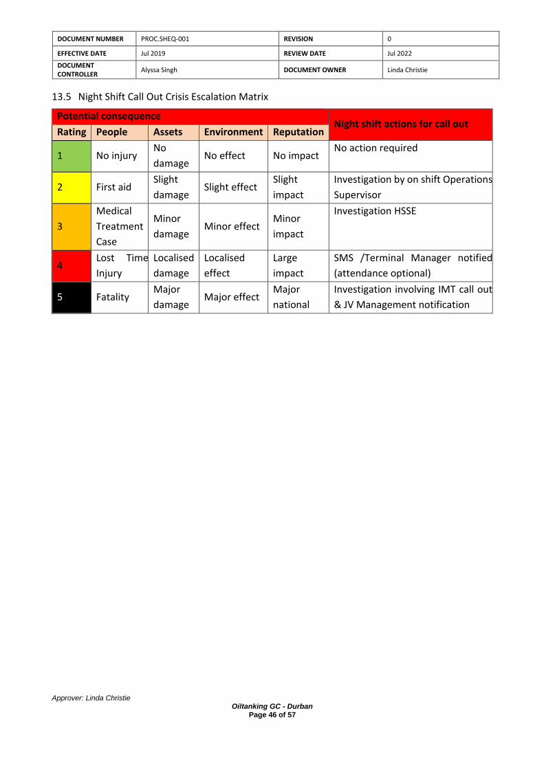
DOCUMENT NUMBER PROC.SHEQ-001 REVISION 0
EFFECTIVE DATE Jul 2019 REVIEW DATE Jul 2022
DOCUMENT CONTROLLER
Alyssa Singh DOCUMENT OWNER Linda Christie
Approver: Linda Christie Oiltanking GC - Durban
Page 46 of 57
13.5 Night Shift Call Out Crisis Escalation Matrix
Potential consequence Night shift actions for call out
Rating People Assets Environment Reputation
1 No injury No
damage No effect No impact
No action required
2 First aid Slight
damage Slight effect
Slight
impact
Investigation by on shift Operations
Supervisor
3
Medical
Treatment
Case
Minor
damage Minor effect
Minor
impact
Investigation HSSE
4 Lost Time
Injury
Localised
damage
Localised
effect
Large
impact
SMS /Terminal Manager notified
(attendance optional)
5 Fatality Major
damage Major effect
Major
national
Investigation involving IMT call out
& JV Management notification

DOCUMENT NUMBER PROC.SHEQ-001 REVISION 0
EFFECTIVE DATE Jul 2019 REVIEW DATE Jul 2022
DOCUMENT CONTROLLER
Alyssa Singh DOCUMENT OWNER Linda Christie
Approver: Linda Christie Oiltanking GC - Durban
Page 47 of 57
13.6 External Emergency Procedure (TNPA)

DOCUMENT NUMBER PROC.SHEQ-001 REVISION 0
EFFECTIVE DATE Jul 2019 REVIEW DATE Jul 2022
DOCUMENT CONTROLLER
Alyssa Singh DOCUMENT OWNER Linda Christie
Approver: Linda Christie Oiltanking GC - Durban
Page 48 of 57
DOCUMENT NUMBER PROC.SHEQ-001 REVISION 0
EFFECTIVE DATE Jul 2019 REVIEW DATE Jul 2022
DOCUMENT CONTROLLER
Alyssa Singh DOCUMENT OWNER Linda Christie
Approver: Linda Christie Oiltanking GC - Durban
Page 49 of 57

DOCUMENT NUMBER PROC.SHEQ-001 REVISION 0
EFFECTIVE DATE Jul 2019 REVIEW DATE Jul 2022
DOCUMENT CONTROLLER
Alyssa Singh DOCUMENT OWNER Linda Christie
Approver: Linda Christie Oiltanking GC - Durban
Page 50 of 57

DOCUMENT NUMBER PROC.SHEQ-001 REVISION 0
EFFECTIVE DATE Jul 2019 REVIEW DATE Jul 2022
DOCUMENT CONTROLLER
Alyssa Singh DOCUMENT OWNER Linda Christie
Approver: Linda Christie Oiltanking GC - Durban
Page 51 of 57

DOCUMENT NUMBER PROC.SHEQ-001 REVISION 0
EFFECTIVE DATE Jul 2019 REVIEW DATE Jul 2022
DOCUMENT CONTROLLER
Alyssa Singh DOCUMENT OWNER Linda Christie
Approver: Linda Christie Oiltanking GC - Durban
Page 52 of 57

DOCUMENT NUMBER PROC.SHEQ-001 REVISION 0
EFFECTIVE DATE Jul 2019 REVIEW DATE Jul 2022
DOCUMENT CONTROLLER
Alyssa Singh DOCUMENT OWNER Linda Christie
Approver: Linda Christie Oiltanking GC - Durban
Page 53 of 57
14 CONTACT DETAILS OILTANKING GC AND NEIGHBOURS
OTGC Emergency Contact Details
Terminal Emergency Contact Details
Name Designation Number
Linda Christie Terminal Manager 082 609 2919
Alyssa Singh HSSE Manager 079 626 8719
Desigan Naidoo Operations Manager 083 607 9014
Sunil Aungadh Transport Manager 083 642 0331
Kavir Baldeo Assistance Transport Manager 082 222 6241
Operations Standby Phone Operations 071 483 3533
Holdings Emergency Contact Details
Nico Smit C.E.O 066 485 2365
Myen Pillay A&O Manager 082 657 7603
OT Emergency Contact Numbers

DOCUMENT NUMBER PROC.SHEQ-001 REVISION 0
EFFECTIVE DATE Jul 2019 REVIEW DATE Jul 2022
DOCUMENT CONTROLLER
Alyssa Singh DOCUMENT OWNER Linda Christie
Approver: Linda Christie Oiltanking GC - Durban
Page 54 of 57
15 SUPPORTING DRAWINGS

15.1 Site layout drawing showing the location of emergency equipment.

DOCUMENT NUMBER PROC.SHEQ-001 REVISION 0
EFFECTIVE DATE Jul 2019 REVIEW DATE Jul 2022
DOCUMENT CONTROLLER
Alyssa Singh DOCUMENT OWNER Linda Christie
Approver: Linda Christie Oiltanking GC - Durban
Page 56 of 57
Key
Forward Control Bag
Fence
Traffic Direction
Smoking Area
Emergency Paths
Opening (Doors and Gates)
Rail Lines
Pump House
Gate G Emergency Stair Exits
Pump House PH + No. General Access Stairs
Over Head Tank OHS Suspended Walk Ways
Receiving Trench RT + No. Underground Storage Tank
Receiving Pit
Tank Capacity Volume (m3)
Mass (T)
Emergency Assembly Point
Tank 1 (T1)
6830 8700 Fire Hose
Tank 2 (T2)
6255 7800 Extinguisher
Tank 3 (T3)
6255 7800 Break Glass Key Access
Tank 4 (T4)
10675 13200 Fire Alarm
Tank 5 (T5)
6513 8500 Stormwater
Tank 6 (T6)
271 325 Sewer
Over Head Tank (OHT)
43 55 Road

DOCUMENT NUMBER PROC.SHEQ-001 REVISION 0
EFFECTIVE DATE Jul 2019 REVIEW DATE Jul 2022
DOCUMENT CONTROLLER
Alyssa Singh DOCUMENT OWNER Linda Christie
Approver: Linda Christie Oiltanking GC - Durban
Page 57 of 57
15.2 Site layout drawing showing key facilities