Embed Size (px)
Citation preview
Proposed Experimental Configurations for Studying Incompressible Flows Prof. Arindam Banerjee, MAE
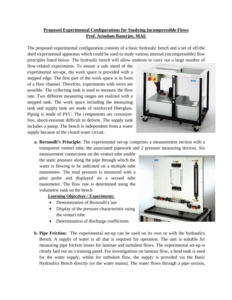
The proposed experimental configuration consists of a basic hydraulic bench and a set of off-the shelf experimental apparatus which could be used to study various internal (incompressible) flow principles listed below. The hydraulic bench will allow students to carry out a large number of flow-related experiments. To ensure a safe stand of the experimental set-ups, the work space is provided with a stepped edge. The first part of the work space is in form of a flow channel. Therefore, experiments with weirs are possible. The collecting tank is used to measure the flow rate. Two different measuring ranges are realized with a stepped tank. The work space including the measuring tank and supply tank are made of reinforced fiberglass. Piping is made of PVC. The components are corrosion-free, shock-resistant difficult to deform. The supply tank includes a pump. The bench is independent from a water supply because of the closed water circuit.
a. Bernoulli’s Principle: The experimental set-up comprises a measurement section with a transparent venturi tube, the associated pipework and 2 pressure measuring devices. Six measurement connections on the venturi tube enable the static pressure along the pipe through which the water is flowing to be indicated on a multiple tube manometer. The total pressure is measured with a pitot probe and displayed on a second tube manometer. The flow rate is determined using the volumetric tank on the bench.
Learning Objectives / Experiments: Demonstration of Bernoulli's law
Display of the pressure characteristic using the venturi tube
Determination of discharge coefficients
b. Pipe Friction: The experimental set-up can be used on its own or with the hydraulics Bench. A supply of water is all that is required for operation. The unit is suitable for measuring pipe friction losses for laminar and turbulent flows. The experimental set-up is clearly laid out on a training panel. For investigations on laminar flow, a head tank is used for the water supply, whilst for turbulent flow, the supply is provided via the Basic Hydraulics Bench directly (or the water mains). The water flows through a pipe section,
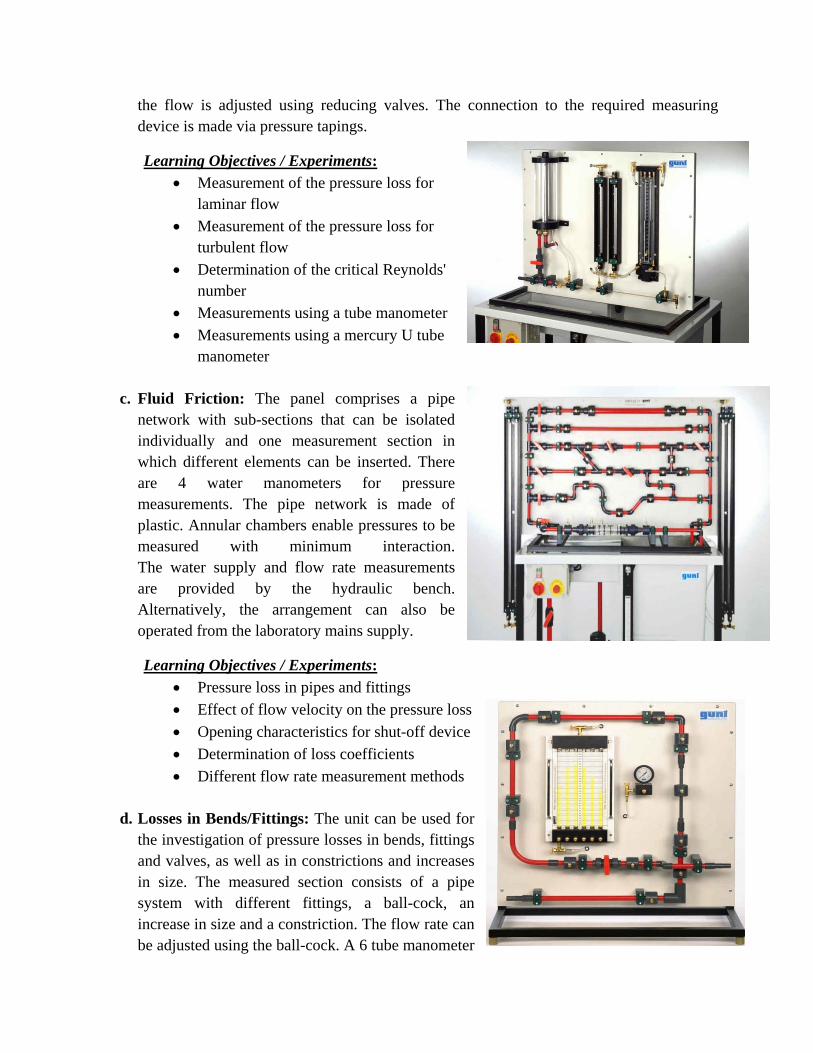
the flow is adjusted using reducing valves. The connection to the required measuring device is made via pressure tapings.
Learning Objectives / Experiments: Measurement of the pressure loss for
laminar flow
Measurement of the pressure loss for turbulent flow
Determination of the critical Reynolds' number
Measurements using a tube manometer
Measurements using a mercury U tube manometer
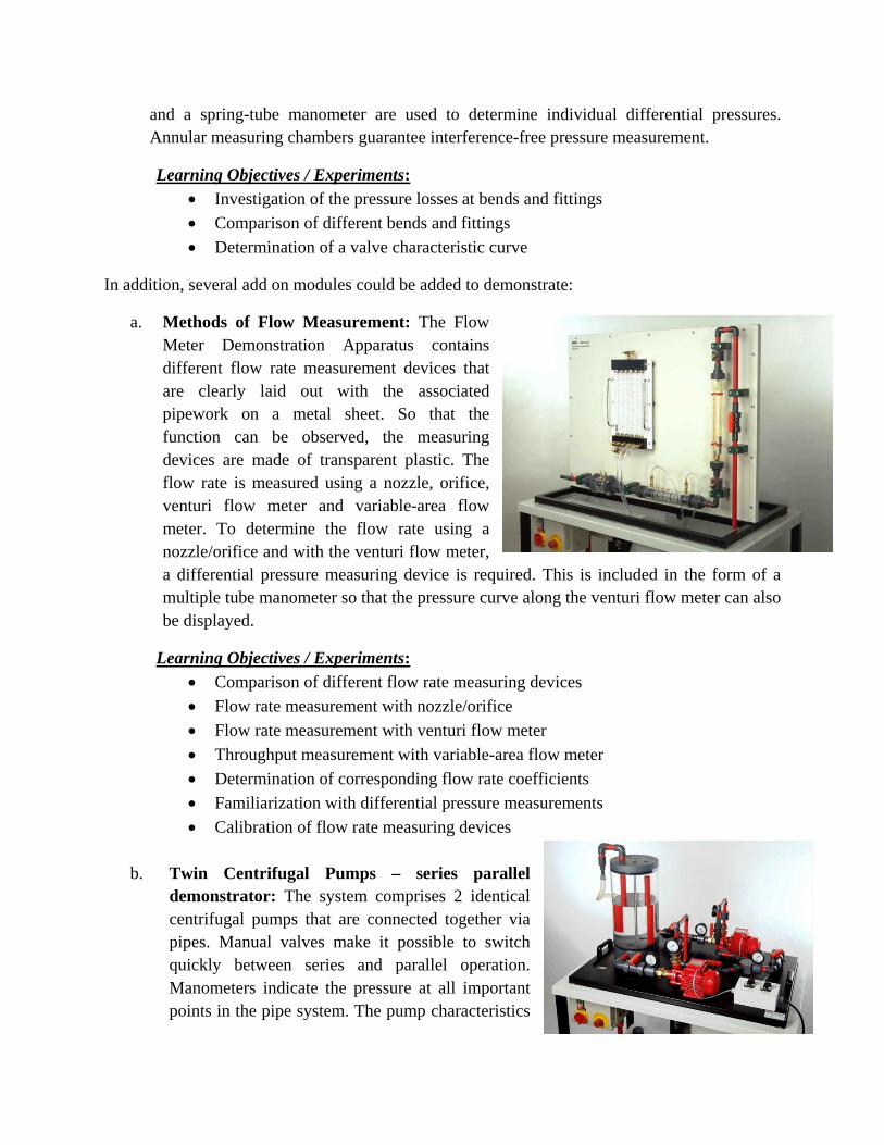
c. Fluid Friction: The panel comprises a pipe
network with sub-sections that can be isolated individually and one measurement section in which different elements can be inserted. There are 4 water manometers for pressure measurements. The pipe network is made of plastic. Annular chambers enable pressures to be measured with minimum interaction. The water supply and flow rate measurements are provided by the hydraulic bench. Alternatively, the arrangement can also be operated from the laboratory mains supply.
Learning Objectives / Experiments:
Pressure loss in pipes and fittings
Effect of flow velocity on the pressure loss
Opening characteristics for shut-off device
Determination of loss coefficients
Different flow rate measurement methods
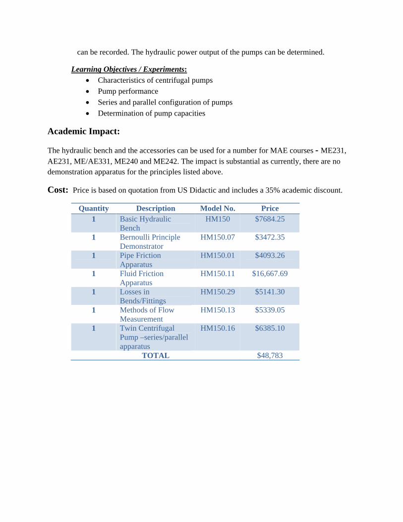
d. Losses in Bends/Fittings: The unit can be used for the investigation of pressure losses in bends, fittings and valves, as well as in constrictions and increases in size. The measured section consists of a pipe system with different fittings, a ball-cock, an increase in size and a constriction. The flow rate can be adjusted using the ball-cock. A 6 tube manometer
and a spring-tube manometer are used to determine individual differential pressures. Annular measuring chambers guarantee interference-free pressure measurement.
Learning Objectives / Experiments: Investigation of the pressure losses at bends and fittings
Comparison of different bends and fittings
Determination of a valve characteristic curve
In addition, several add on modules could be added to demonstrate:
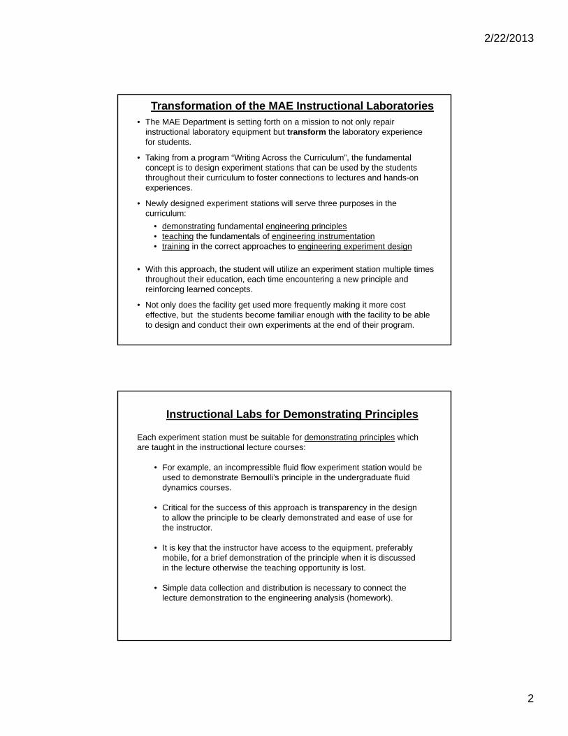
a. Methods of Flow Measurement: The Flow Meter Demonstration Apparatus contains different flow rate measurement devices that are clearly laid out with the associated pipework on a metal sheet. So that the function can be observed, the measuring devices are made of transparent plastic. The flow rate is measured using a nozzle, orifice, venturi flow meter and variable-area flow meter. To determine the flow rate using a nozzle/orifice and with the venturi flow meter, a differential pressure measuring device is required. This is included in the form of a multiple tube manometer so that the pressure curve along the venturi flow meter can also be displayed.
Learning Objectives / Experiments: Comparison of different flow rate measuring devices
Flow rate measurement with nozzle/orifice
Flow rate measurement with venturi flow meter
Throughput measurement with variable-area flow meter
Determination of corresponding flow rate coefficients
Familiarization with differential pressure measurements
Calibration of flow rate measuring devices
b. Twin Centrifugal Pumps – series parallel demonstrator: The system comprises 2 identical centrifugal pumps that are connected together via pipes. Manual valves make it possible to switch quickly between series and parallel operation. Manometers indicate the pressure at all important points in the pipe system. The pump characteristics
can be recorded. The hydraulic power output of the pumps can be determined.
Learning Objectives / Experiments:
Characteristics of centrifugal pumps
Pump performance
Series and parallel configuration of pumps
Determination of pump capacities
Academic Impact:
The hydraulic bench and the accessories can be used for a number for MAE courses - ME231, AE231, ME/AE331, ME240 and ME242. The impact is substantial as currently, there are no demonstration apparatus for the principles listed above.
Cost: Price is based on quotation from US Didactic and includes a 35% academic discount.
Quantity Description Model No. Price 1 Basic Hydraulic
Bench HM150 $7684.25
1 Bernoulli Principle Demonstrator
HM150.07 $3472.35
1 Pipe Friction Apparatus
HM150.01 $4093.26
1 Fluid Friction Apparatus
HM150.11 $16,667.69
1 Losses in Bends/Fittings
HM150.29 $5141.30
1 Methods of Flow Measurement
HM150.13 $5339.05
1 Twin Centrifugal Pump –series/parallel apparatus
HM150.16 $6385.10
TOTAL $48,783

2/22/2013
1
Transformation of the Instructional Laboratories
Department of Mechanical and Aerospace Engineering
October 6, 2011
• Unfortunately the elimination of State resources for the laboratories (e.g. engineering equipment bill, $000 per graduate) over the past 10 years has resulted in most experiment stations being in questionable repair and often quite unpredictable.
• Faculty and GTAs are often left in the unenviable position of describing what should have happened, or worse, students attempt to explain results that shouldn’t have happened.
• Currently the instructional laboratories in the department consist of a series of prescribed experiments, typically conducted for the students, in a two or three course sequence over the undergraduate curriculum.
• The typical entering student typically has very limited hands-on experience compared to the student of 20 years ago.
• Most experiment stations are used by a student once in their undergraduate education. Typically, this experience is not in parallel with the teaching of the engineering principle in the lecture, hence a critical teaching moment is lost.
Current State of the MAE Instructional Laboratories
2/22/2013
2
• The MAE Department is setting forth on a mission to not only repair instructional laboratory equipment but transform the laboratory experience for students.
• Taking from a program “Writing Across the Curriculum”, the fundamental concept is to design experiment stations that can be used by the students throughout their curriculum to foster connections to lectures and hands-on experiences.
• Newly designed experiment stations will serve three purposes in the curriculum:
• demonstrating fundamental engineering principles• teaching the fundamentals of engineering instrumentation• training in the correct approaches to engineering experiment design
• With this approach, the student will utilize an experiment station multiple times throughout their education, each time encountering a new principle and reinforcing learned concepts.
• Not only does the facility get used more frequently making it more cost effective, but the students become familiar enough with the facility to be able to design and conduct their own experiments at the end of their program.
Transformation of the MAE Instructional Laboratories
Each experiment station must be suitable for demonstrating principles which are taught in the instructional lecture courses:
• For example, an incompressible fluid flow experiment station would be used to demonstrate Bernoulli’s principle in the undergraduate fluid dynamics courses.
• Critical for the success of this approach is transparency in the design to allow the principle to be clearly demonstrated and ease of use for the instructor.
• It is key that the instructor have access to the equipment, preferably mobile, for a brief demonstration of the principle when it is discussed in the lecture otherwise the teaching opportunity is lost.
• Simple data collection and distribution is necessary to connect the lecture demonstration to the engineering analysis (homework).
Instructional Labs for Demonstrating Principles
2/22/2013
3
Each experiment station must be constructed to teach fundamentals of engineering experimentation:
• Fundamentals include:• Characteristics of sensors• Sensor selection (and what can occur with the wrong choice)• Systems of sensors• Uncertainty principles.
• Using the example of the incompressible fluid flow station, several types of pressure and flow transducers would be incorporated to illustrate principles of operation and the importance of correct sensor choice.
Instructional Labs for Teaching Engineering Experiments
Each experiment station must be flexible and capable of reconfiguration. This is critical to make the facility available for students designing their own experiments:
• Currently students are often tasked with designing and conducting experiments either through assigned lab course work or as part of an extracurricular design competition. Critical is having experiment stations that are flexible and user-friendly enough to be used as part of these learning experiences.
• Again using the example of the incompressible flow experiment facility, students could design an experiment to measure flow losses in a piping system to validate loss coefficients or to calibrate flow sensors. This flexibility in the experiment stations allows the students to be introduced to the facility early in the curriculum and to put them to use throughout their educational experience.
• The experiment stations must include modern aspects of computer data acquisition and control, integral to the systems. The experiment stations ideally would serve as a teaching tool for the principles of data acquisition systems and computer control of mechanical and aerospace systems.
Instructional Labs for Student Design of Experiments
2/22/2013
4
Possible Experimental Facilities:
1. Incompressible, internal flowe.g. flow measurement, pressure measurement, Bernoulli’s equation, flow losses
2. Compressible, external flowe.g. airfoils, flow separation, lift, drag, etc. This would be an upgrade of existing wind tunnel.
3. Driven dynamical system e.g. dynamic model validation, accelerometers, force/velocity measurement, etc.
4. Rotating machinery systeme.g. angular speed measurement, balancing, etc.
5. Fixed mass thermodynamic systeme.g. piston-cylinder arrangement, pressure measurement, isentropic/polytropic compression, etc.
6. Heat transfer/heat exchanger system
Instructional Labs
How do we get there?
• Obtain external funding for instructional laboratory development: Each experiment station is estimated to cost $80,000 with a planned five new stations over five years. Hence one-time cost dollars of $80,000 per year for five years is required for initial equipment purchases.
• Provide continuous staff/faculty support for laboratory development, maintenance and improvement (hire for specific purpose):It is proposed that an endowment be established for funding a staff position in the department to maintain and further develop these experiment stations. Additionally the endowment should provide roughly $30,000 per year for annual maintenance and development. A $1.8M to $2M endowment would be required to meet these objectives.
• First lab station (incompressible flow) identified, specifications identified and preliminary costs determined. Lab stations for future years need to be defined (need faculty advocate for each)
Instructional Labs
b1
2/22/2013
5
Incompressible Flow Facility
Requirements
• Should be able to handle both high flow / pressure regimes
• Teach and demonstrate a wide variety of fluid mechanics principles (both fundamental and applied)
• Provide students with hands-on experience on flow transducers and their characteristics (including calibration, sizing and selection criteria)
• Should be used for student projects (ME261) and other advanced experiments
• Used for instruct across curriculum – fundamental courses (ME231, AE 231), Lab Courses (ME240 & 242), Senior Design (ME261) and Technical electives (ME/AE 331)
Solution
• Fully integrated two part system– Low pressure unit for demonstration of
principles– High pressure unit for hands-on training
on flow transducers
• Low pressure unit to have detachable modules to move and reconfigure for in class demonstrations
• High Pressure Unit to be a fixed unit for various instructional tasks in ME 240 and 242.
• Combined data acquisition• Both units to be set up together as an
incompressible flow facility to share resources
• Connections for defined instructional tasks and other flexible tasks
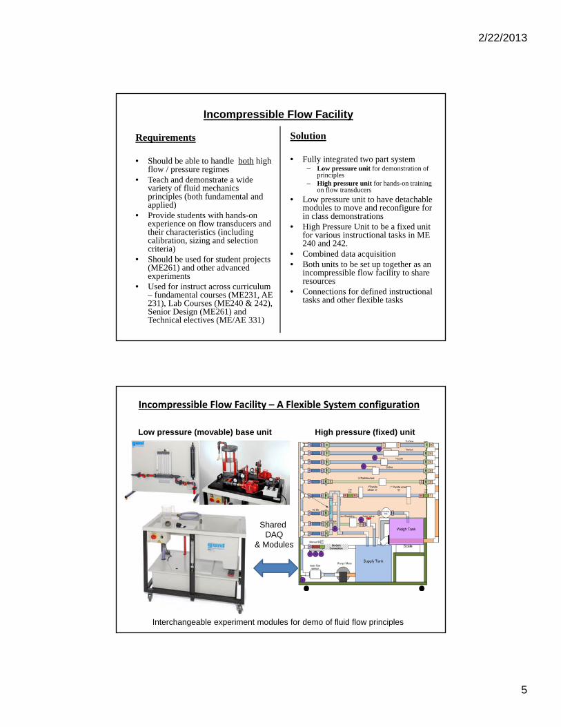
Incompressible Flow Facility – A Flexible System configuration
Low pressure (movable) base unit
Interchangeable experiment modules for demo of fluid flow principles
High pressure (fixed) unit
Shared DAQ
& Modules
2/22/2013
6
Low Pressure Unit ‐ Instructional Activities
Specific Aim: Demonstration fundamental fluid flow principles. The movable unit will demonstrate:• Bernoulli’s principle• Frictional losses in pipes and fittings • Laminar / turbulent flow• Methods of flow measurements
– Manometer measurement– Comparison of pressure loss in orifice / nozzle
/ venturi meters– Differential pressure measurements– Throughput measurements with
variable area flow meter
• Centrifugal Pump Performance– Pump sizing– Generation of system curves– Series Parallel demonstration– Determination of pump types using specific
speed
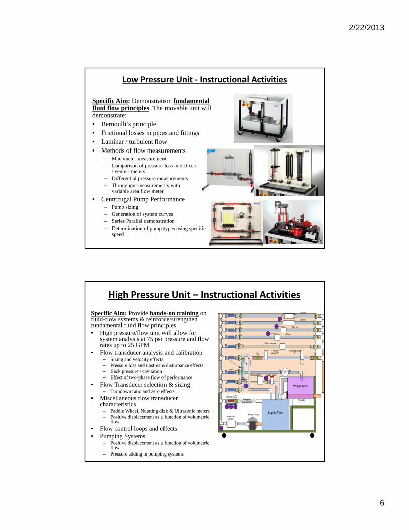
High Pressure Unit – Instructional Activities
Specific Aim: Provide hands-on training on fluid-flow systems & reinforce/strengthen fundamental fluid flow principles. • High pressure/flow unit will allow for
system analysis at 75 psi pressure and flow rates up to 25 GPM
• Flow transducer analysis and calibration – Sizing and velocity effects– Pressure loss and upstream disturbance effects– Back pressure / cavitation– Effect of two-phase flow of performance
• Flow Transducer selection & sizing– Turndown ratio and zero effects
• Miscellaneous flow transducer characteristics
– Paddle Wheel, Nutating disk & Ultrasonic meters – Positive displacement as a function of volumetric
flow
• Flow control loops and effects• Pumping Systems
– Positive displacement as a function of volumetric flow
– Pressure adding in pumping systems
2/22/2013
7
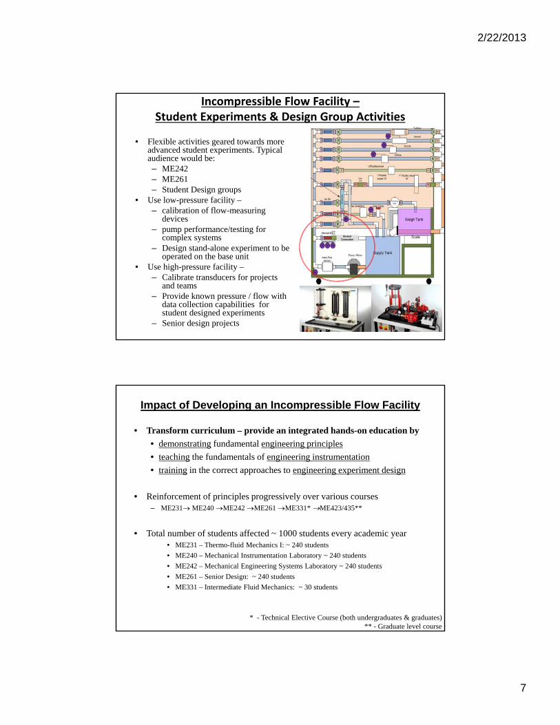
• Flexible activities geared towards more advanced student experiments. Typical audience would be:– ME242– ME261– Student Design groups
• Use low-pressure facility –– calibration of flow-measuring
devices– pump performance/testing for
complex systems– Design stand-alone experiment to be
operated on the base unit• Use high-pressure facility –
– Calibrate transducers for projects and teams
– Provide known pressure / flow with data collection capabilities for student designed experiments
– Senior design projects
Incompressible Flow Facility –Student Experiments & Design Group Activities
Impact of Developing an Incompressible Flow Facility
• Transform curriculum – provide an integrated hands-on education by
• demonstrating fundamental engineering principles
• teaching the fundamentals of engineering instrumentation
• training in the correct approaches to engineering experiment design
• Reinforcement of principles progressively over various courses – ME231 ME240 ME242 ME261 ME331* ME423/435**
• Total number of students affected ~ 1000 students every academic year • ME231 – Thermo-fluid Mechanics I: ~ 240 students
• ME240 – Mechanical Instrumentation Laboratory ~ 240 students
• ME242 – Mechanical Engineering Systems Laboratory ~ 240 students
• ME261 – Senior Design: ~ 240 students
• ME331 – Intermediate Fluid Mechanics: ~ 30 students
* - Technical Elective Course (both undergraduates & graduates)** - Graduate level course
2/22/2013
8
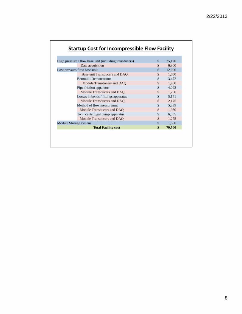
Startup Cost for Incompressible Flow Facility
High pressure / flow base unit (including transducers) $ 25,120 Data acquisition $ 6,300
Low pressure/flow base unit $ 12,000 Base unit Transducers and DAQ $ 1,050
Bernoulli Demonstrator $ 3,472 Module Transducers and DAQ $ 1,950
Pipe friction apparatus $ 4,093 Module Transducers and DAQ $ 1,750
Losses in bends / fittings apparatus $ 5,141 Module Transducers and DAQ $ 2,175
Method of flow measuremnt $ 5,339 Module Transducers and DAQ $ 1,950
Twin centrifugal pump apparatus $ 6,385 Module Transducers and DAQ $ 1,275
Module Storage system $ 1,500 Total Facility cost $ 79,500