Embed Size (px)
Citation preview

12/23/2014 1:49 PM
Page1
Bid #:
422
Proposal Option List
12/23/2014
Customer: Florida Sheriffs Association Bid Number: 422 Representative Jones, Mark
Job Number:
Organization: Ten-8 Fire Equipment, Inc Bid Date: 01-16-2015 Requirements Manager:
Stock Number:
Description: Spec #17 Peterbilt Commercial Pumper
DBVersion: 02.00.0578.0000 Body: Pumper, Medium, Aluminum, 2nd Gen, Saber/Commercial Chassis: Peterbilt 337, 4x2 Single Rear Axle, WITH PRICING
Line Option Type Option Description Qty
1 0074080 Build-to-Order, Pierce Florida Product 1
2 0010012 No Boiler Plates requested 1
3 0584455 Manufacture Location: Bradenton, Florida 1
4 0584453 RFP Location: Bradenton, Florida 1
5 0588609 Vehicle Destination, US 1
6 0018257 Commercial chassis & Snorkel products 1
7 0542373 Comply NFPA 1901 Changes Effect Jan 1, 2009, With Exceptions, Commercial Chassis
1
8 0533347 Pumper/Pumper with Aerial Device Fire Apparatus 1
9 0588611 Vehicle Certification, Pumper 1
10 0568412 Agency, Apparatus Certification, Pumper/Tanker, Third Party, PMFD
1
11 0012771 Stock/Demo No Fire Department 1
12 0536644 Customer Service Website 1
13 0537375 Unit of Measure, US Gallons 1
14 0000005 Bid Bond, 10% 1
15 0540326 Performance Bond, Not Requested 1
16 0000007 Approval Drawing 1
17 0589819 Electrical Diagrams, Commercial 1
18 0586588 Peterbilt 337, 4x2 Single Rear Axle, WITH PRICING 1
19 0629699 Base Price, Peterbilt 337, 4x2 - Pricing Level 5/7/2014 1
20 0567687 Wheelbase, Peterbilt, Up to 219" 1
Wheelbase - 189.5"
21 0584367 GVW Rating, Commercial Chassis 1
GVW rating - 35,000 lbs.
22 0529927 Frame, Chassis, 10.62", 120,000 PSI, Kw, Pete 1
23 0584366 Frame Liner not Req'd, Commercial Chassis 1
24 0582447 Axle, Front, Dana Spicer, 12K, Peterbilt 1
25 0567763 Suspension, Front Spring, 12,000 lb, Peterbilt 1
26 0073051 Shock Absorbers, Front 1
27 0585785 Bridgestone Tires (Default Brand) 1
28 0693853 Tires, Bridgestone, 11R22.50 1
29 0629690 Wheel,Steel, 22.50" x 8.25", Kw/Pete, Pierce Painted 1
30 0582435 Axle, Rear, Dana Spicer S23-170, 23,000 lb, Peterbilt 1
31 0544651 Top Speed of Vehicle, 60 MPH, Commercial Chassis 1
32 0567695 Suspension, Rear Spring, Reyco 23,000 lb, w/ Aux, Kw/Peterbilt 1
33 0693869 Tires, Bridgestone, 11R22.50 1

12/23/2014 1:49 PM
Page2
Bid #:
422
34 0629685 Wheel, Steel, 22.50" x 8.25", Commercial Chassis, Kw/Pete, Pierce Painted
1
35 0620570 Tire Pressure Monitoring, RealWheels, AirSecure, Valve Cap, Single Axle
1
Qty, Tire Pressure Ind - 6
36 0002045 Mud Flaps, w/logo front & rear 1
37 0532930 Chocks, Wheel, Pumper, Provided by Fire Department 1
38 0544690 Mounting Brackets, Chocks, Provided by Fire Department 1
39 0567694 ABS, Bendix Anti-Lock Braking System, Peterbilt 1
40 0012013 Brakes, Cam Front, 16.50"x 5.00" Kw/Pete 1
41 0555998 Air Compressor, Brake, Cummins/PX-8, 18.7 CFM, Kw/Pete 1
42 0665853 Air Dryer, Brake, AD-IS w/Heater, Peterbilt 1
43 0010574 Air Inlet, w/Disconnect Coupling, Commercial Chassis 1
Location, Air Coupling(s) - y) DS Step Area
44 0650959 Engine, Paccar PX-9, 350 hp, Peterbilt, 2013 Emissions 1
45 0001247 High Idle w/Electronic Engine, Commercial 1
46 0567774 Auxiliary Brake, Turbo Exhaust Brake, Peterbilt 1
47 0567668 Air Intake, w/Ember Separator, Supplier Installed, Peterbilt 1
48 0586931 Exhaust System, 2010, Horizontal, RH Step Mounted DPF/SCR, 2/4 Door, KW/Pete
1
49 0584339 Exhaust Modifications, Kw / Peterbilt, Horizontal, PS Exit 1
50 0589029 Coolant Hoses, Silicone, Radiator and Heater, Commercial Chassis
1
51 0567675 Fuel Tank, 50 Gallon, Left Side, Polished Aluminum, Peterbilt 1
52 0654889 DEF Tank, 11 gallon, LH, Bright Wrap, KW T370, PB 1
53 0552793 Not Required, Fuel Priming Pump 1
54 0552712 Not Required, Shutoff Valve, Fuel Line 1
55 0023746 Cooler, Chassis Fuel, Not Req'd. 1
56 0567781 Trans, Automatic, Allison 3000 EVS, w/(2) PTO Provisions, Peterbilt
1
57 0024593 Transmission, Shifter, Push Button, 5 Speed, KW/Pete 1
Trans, ratio - 3000 EVS, 5Spd
58 0012875 Transmission Oil Cooler, External, Commr 1
59 0011370 Driveline, Commr Chassis 1
60 0567701 Steering, TRW TAS 65, Tilt/Telescoping, Peterbilt, Kw 1
61 0585826 Bumper, Aerodynamic, Chromed Steel, Non-extd, Peterbilt 1
62 0545321 Tow Pins, Front, Kw, Peterbilt 1
63 0072224 Bumper Gap, Commercial 1
64 0041856 Cab, Peterbilt, 2-door 1
65 0566857 Cab Interior, Peterbilt, Grey/Black 1
66 0582771 Grille, Polished Stainless Steel, Peterbilt 1
67 0567679 Mirrors, Stainless Steel, Heated & Remote, Convex, Peterbilt 1
68 0027014 Window, Peeper Window RH Door 1
69 0567762 Step Package, Standard, Peterbilt 2-Door, NFPA Compliant 1
70 0509487 Lights, Cab Access Steps, P25, LED, 4 Lights 1
71 0567684 Air Conditioning, Peterbilt 1
72 0005940 Lights, Engine Compt, (2) Commercial Chassis 1
73 0030874 Console, KW/Pete, Two (2) Door, Radios, Map Storage 1
74 0584368 Seating Capacity, Cab, Commercial, NOT FOR FUTURE USE 2

12/23/2014 1:49 PM
Page3
Bid #:
422
Qty, - 02
75 0624102 Seating Capacity, Cab, 2-Door, Commercial 2
Qty, - 02
76 0585847 Seats, Cab, Air driver w/Air Companion Seat, Peterbilt 1
77 0073999 No Crew Cab Seats, 2-door cab 1
78 0551164 Seat Belt Web Length, Commercial Chassis 1
79 0584364 Seat Belts, Red, Commercial Chassis 1
80 0691237 Seat Belt Monitoring System 1
81 0543917 Helmet Storage, Provided by Fire Department 1
82 0556289 Lights, Dome, Weldon, 8081-8000-13 Red/Clear LED, Grey Bezel
1
Qty, - 01
Location - overhead
83 0544332 Portable Hand Light, Provided by Fire Department, Pumper NFPA Classification
1
84 0584358 Cab Instrumentation, Commercial Chassis 1
85 0034643 Panel, Emergency Switch, Located In Floor Mt'd Console 1
86 0005937 Light, Do not move apparatus, Commercial 1
Alarm, Do Not Move Truck - Steady Alarm
87 0005926 Light, Open Door - Commercial Std 1
88 0072620 Wiper control, intermittent feature Commercial 1
89 0637219 No RADIO, AM/FM 1
90 0626864 Not Required, Vehicle Information Center, No Multiplex System 1
91 0535234 Vehicle Data Recorder, Single Module 1
92 0622833 Traditional Direct Wired Electrical System, Commercial Chassis 1
93 0623076 Electrical System, Peterbilt 337, Pumper 1
94 0583990 Single Start, (2) PACCAR Premium, 2000 CCA 1
95 0583991 Batteries Relocated by Pierce, 2-Door Cab 1
Location, Batteries - DS Front Compt
96 0072685 Selector, Single Start Battery, Commercial Chassis 1
97 0036234 Receptacle, Battery Charging, Cab Step Area, Driver's Side 1
98 0012778 No Pick Required, Battery Charger Location 1
99 0530960 Not Required, Remote Battery Charger Indicator 1
100 0567771 Alternator, 270 amp, Kw/Peterbilt 1
101 0002765 Load Manager, Kussmaul Mark IV, (10) Channel 1
102 0517187 Cab Lighting, LED Marker Lights, Commercial Chassis 1
103 0627282 Lights, Clearance/Marker/ID, Rear, FRP LED Bar & P25 LED 4Lts
1
104 0535835 Lights, Tail, Weldon 3884-0100-1*, Tri-Lamp Cluster, LED Stop/Tail, Turn & Bckup
1
105 0085910 Lights, Backup Included in Signal Cluster 1
106 0664481 Bracket, License Plate & Light, P25 LED 1
107 0589905 Alarm, Back-up Warning, PRECO 1040 1
108 0654479 Lights, Perimeter Scene Cab Exits, TecNiq E10-WS00-1 LED, Angled Brkt, 2 Dr
1
Z location - *
109 0667322 Lights, Perimeter Scene, Truck-Lite 6060C LED Grmt (4) Lts Pump Panel/Rear Step
1
Switch, Location, Perim - cab rocker switch

12/23/2014 1:49 PM
Page4
Bid #:
422
110 0556360 Lights, Step, P25 LED 4lts, Pump Pnl Sw 1
111 0005955 Lights, Deck, Unity (2) AG, Rear, (1) Spot, (1) Flood 1
112 0645676 Lights, Not Required, Hose Bed, Deck Lights At Rear 1
113 0645681 Lights, Not Required, Rear Work, Deck Lights At Rear 1
114 0693709 Pumper, Medium, Aluminum, 2nd Gen, Saber/Commercial 1
115 0692368 Florida Value Discount, 2nd Generation Pumper 1
116 0554271 Body Skirt Height, 20" 1
117 0028245 Tank, Water, 750 Gallon, Poly, Med 1
118 0003405 Overflow, 4" Water Tank, Poly 1
119 0028107 Not Required, Foam Cell Modification 1
120 0553729 Not Required, Restraint, Water Tank, Heavy Duty 1
121 0003429 No Direct Tank Fill Req'd 1
122 0003424 (No Dump Valve required) 1
123 0048710 Jet Assist Not Req'd 1
124 0030007 (No Dump Chute Required) 1
125 0514778 Not Required, Switch, Tank Dump Master 1
126 0689065 Hose Bed, Aluminum, Saber/Commercial 1
127 0003480 Hose Bed Capacity, Std, 1500' of 2.5", 400' of 1.5" 1
128 0083488 Divider, Hose Bed, .25" Unpainted 1
Qty, Hosebed Dividers - 1
129 0589278 Hose Restraint, Hose Bed, Velcro Strap on Top, 2" Heavy Nylon Web at Rear
1
Type of fastener - 2" cam buckle
Nylon Web Color - Black
Type of fastener, Rear - 2" cam buckle - bottom of hosebed
130 0013512 Running Boards, 12.75" Deep 1
131 0686069 Tailboard, 16" Deep, Full Width, Angled Corners 1
132 0690027 Wall, Rear, Smooth Aluminum/Body Material, Flush Rear Wall 1
133 0035470 Tow Eyes, (2) Painted, Direct to Frame 1
134 0003561 Construction, Compt, Alum, Pumper 1
135 0083602 DS 136" Lap, Full Height Front & Rear 1
136 0083614 PS 136" Lap, Low 1
137 0063911 Doors, Lap w/ "D" Handles - Side Compartments 1
138 0083701 Rear, Rollup, 44.50" FF 1
139 0692746 Doors, Gortite, Rollup, Rear Compartment 1
Color,Gortite,Roll-upDoor - Satin finish
Latch, Gortite, Roll-up - Non-locking Liftbar
140 0689545 Lights, Compt, Pierce LED, Single Light Strip, NFPA 2009 Minimum
6
Location - all compartments
Qty, - 06
141 0687139 No Shelf Tracks Required 1
142 0539177 Rub Rail, Aluminum Extruded, Side and Rear Body, Xtra Space (.50")
1
143 0039041 Not Required, Fender Crowns, Rear 1
144 0519849 Not Required, Hose, Hard Suction 1
145 0626229 Handrails, Side Pump Panels, Per Print 1

12/23/2014 1:49 PM
Page5
Bid #:
422
146 0004126 Handrails, Beavertail, Standard 1
147 0004146 Handrail, Rear, Below Hose Bed, Full Width 1
148 0004264 Ladder, 24' Alco-Lite PEL-24 2 Sect 1
149 0004266 Ladder, 14' Alco-Lite, PRL-14, Roof 1
150 0004300 Brackets, Adjustable, PS 1
151 0034270 Ladder, Folding, 10' Alco-Lite FL-10 1
Location, Fold Ladder - a) Right Compt
152 0554062 Pike Pole, 10' Akron, Fiberglass, Pumper NFPA Classification 2
Qty, Pike Poles - 2
Location - on passenger side
153 0638855 Pike Pole, 6', Pumper, Provided by Fire Department 1
Pike Pole Make/Model - Akron 6' Pike Pole
154 0004360 Tulip Clip Holders For Pike Poles, Pierce Furnished Pike Poles 1
Location - on passenger side, under the ladders
155 0024388 No Steps Required, Front Of Body 1
156 0592995 Steps, Combo Folding Trident w/LED & Corner, Rear Body 1
Coating, Step - luminescent
157 0004415 Pump, Waterous, CS, 1250 GPM, Single Stage 1
158 0004481 Packing, Grafoil, Waterous 1
159 0091446 Pump Setup Charges N/A 1
160 0559769 Transmission, Pump, Waterous C20 Series 1
161 0535256 Shift, Air w/ Manual Override, Split Shaft, Waterous 1
162 0003148 Transmission Lock-up, EVS 1
163 0004547 Auxiliary Cooling System 1
164 0014486 (No Transfer Valve Required on 1 Stage Pump) 1
165 0004517 Valve, Relief Intake, Elkhart 1
166 0645706 Controller, Pressure, Class 1 Sentry 1
167 0641743 Primer, Waterous, VPO Motor, (1) VAP Valve, (1) Push Button Control
1
168 0058516 Manuals, Pump (2), CD 1
169 0089351 Plumbing, Stainless Steel & Hose, Control Zone 1
170 0089437 Plumbing without Foam System 1
171 0004645 Inlets, 6.00" - 1250 GPM or Larger Pump 1
172 0004646 Cap, Main Pump Inlet, Long Handle, NST, VLH 1
173 0084610 Valves, Akron 8000 series- All 1
174 0004660 Inlet, Left Side, 2.50" 1
175 0029147 Not Required, Inlet, Right Side 1
176 0016158 Valve, Inlet(s) Recessed, Side Cntrl, "Control Zone" 1
Qty, Inlets - 1
177 0004700 Control, Inlet, at Valve 1
178 0092569 No Rear Inlet (Large Dia) Requested 1
179 0092696 Not Required, Cap, Rear Inlet 1
180 0064116 No Rear Inlet Actuation Required 1
181 0009648 No Rear Intake Relief Valve Req'd 1
182 0092568 No Rear Auxiliary Inlet Requested 1
183 0563738 Valve, .75" Bleeder, Aux. Side Inlet, Swing Handle 1
184 0029043 Tank to Pump, (1) 3.00" Valve, 3.00" Plumbing 1

12/23/2014 1:49 PM
Page6
Bid #:
422
185 0004910 Outlet, 2.00" Tank Fill 1
186 0004940 Outlet, Left Side, 2.50" 2
Qty, Discharges - 02
187 0092570 Not Required, Outlets, Left Side Additional 1
188 0004945 Outlet, Right Side, 2.50" 1
Qty, Discharges - 01
189 0092571 Not Required, Outlets, Right Side Additional 1
190 0029137 Not Required, Outlet, Large Diameter 1
191 0092572 Not Required, Outlet, Front 1
192 0004995 Outlet, Rear, 2.50" 1
Qty, Discharges - 01
Location, Outlet - a) passenger's side
193 0092574 Not Required, Outlet, Rear, Additional 1
194 0092573 Not Required, Outlet, Hose Bed/Running Board Tray 1
195 0085076 Caps for 1.50" to 3.00" Discharge, VLH 1
196 0563739 Valve, 0.75" Bleeder, Discharges, Swing Handle 1
197 0005091 Elbow, Left Side Outlets, 45 Degree, 2.50" FNST x 2.50" MNST, VLH
1
198 0035094 Not Required, Elbow, Left Side Outlets, Additional 1
199 0025091 Elbow, Right Side Outlets, 45 Degree, 2.50" FNST x 2.50" MNST, VLH
1
200 0089584 Not Required, Elbow, Right Side Outlets, Additional 1
201 0045091 Elbow, Rear Outlets, 45 Degree, 2.50" FNST x 2.50" MNST, VLH 1
202 0085695 Not Required, Elbow, Rear Outlets, Large, Additional 1
203 0007308 Not Required, Elbow, Large Diameter Outlet 1
204 0062133 Control, Outlets, Manual, Pierce HW if applicable 1
205 0005065 Outlet, 3.00" Deluge Riser 1
206 0029302 No Monitor Requested 1
207 0029304 No Nozzle Req'd 1
208 0005070 Deluge Mount, NPT 1
209 0029167 Crosslays Sngl Sheet unpainted, (2+) 1.50", Std. Cap 2
Qty, Crosslays - 2
210 0029196 Not Required, 2.50" Crosslay 1
211 0029260 Not Required, Speedlays 1
212 0591145 Hose Restraint, Crosslay/Deadlay, Top and Ends, Elastic Netting 2
Qty, - 02
213 0044333 Not Required, Foam System 1
214 0012126 Not Required, CAF Compressor 1
215 0552517 Not Required, Refill, Foam Tank 1
216 0042573 Not Required, Foam System Demonstration 1
217 0045465 Not Required, Foam Tanks 1
218 0091110 Not Required, Foam Tank Drain 1
219 0091079 Not Required, Foam Tank #2 1
220 0091112 Not Required, Foam Tank Drain 1
221 0007545 Pump House, Side Control, 45", Control Zone 1
222 0032479 Pump Panel Configuration, Control Zone 1
223 0629252 Material, Pump Panels, Side Control Black Vinyl 1

12/23/2014 1:49 PM
Page7
Bid #:
422
Material Finish, Pump Panel, Side Control - Black Vinyl
Material, Pump Panel, Side Control - Aluminum
224 0005578 Panel, Pump Access - Pass Side Only 1
225 0035501 Pump House Structure, Std Height 1
226 0005945 Light, Pump Compt 1
227 0586382 Engine Indicators, Included With Pressure Controller 1
228 0005601 Throttle Included w/ Pressure Controller 1
229 0549333 Indicators, Engine, Included with Pressure Controller 1
230 0511078 Gauges, 4.00" Master, Class 1, 30"-0-600psi 1
231 0511100 Gauge, 2.00" Pressure, Class 1, 30"-0-400psi 1
232 0062586 Gauge, Water Level, Class 1, Pierce Std 1
233 0006774 Not Required, Foam Level Gauge 1
234 0593161 Light Shield, S/S LED 1
235 0508023 Air Horns, (2) Hadley 6" Round, On Sides Of Engine Hood 1
236 0036062 Control, Air Horn, Horn Ring, PS Lanyard 1
237 0525667 Siren, Whelen 295SLSA1, 100 or 200 Watt 1
238 0567686 Location, Elect Siren, In Console, Peterbilt 1
239 0006145 Control, Elec Siren, Horn Ring, PS Foot Sw 1
240 0550225 Speaker, Whelen SA314A, 100 watt, Cast Aluminum w/ Natural Finish
1
Qty, Speakers - 1
Connection, Speaker - siren head
241 0548352 Location, Recessed in the Front Bumper, Driver Side 1
242 0671616 Lightbar, Code 3, 21TR47NFPA1 LED 1
243 0537471 Lights, Front Zone, Code 3, 378XBZ-75, PRIZM LED, Colored Lens
1
Color, Lt DS Front - Red
Color, Lt PS Front - Red
244 0078240 Lights, Side Zone Lower, Code 3 65 LED, 2pr 1
Location, lights rear - over rear wheel wells
Location, Lights Frt Side - a)each side engine hood
Flange Kit, 2pr - w/o with out a flange
Color,Code-3,65 LED,FRT - a) rd/rd
Color,Code-3,65 LED,BCK - a) rd/rd
245 0074717 Lights, Rear Zone Lower, Code-3 65 LED 1
Flange Kit - w/o) with out flange
Color,Code-3,65 LED - a) rd/rd
246 0655422 Light, Rear Zone Upper, Code-3, DuoBeam II, DB2-2TCNFPA LED Red Beacon, TC6
1
Color, Dome, Rear Warning - j) both domes clear
247 0006551 Not Required, Lights, Rear Upper Zone Blocking 1
248 0016610 Mtg, Rear Warn Lts, Std Mount, S/S Brkts 1
249 0519934 Not Required, Brand, Hydraulic Tool System 1
250 0007150 Bag of Nuts and Bolts 1
Qty, Bag Nuts and Bolts - 1
251 0532883 NFPA Required Loose Equipment, Pumper, Provided by Fire Department
1

12/23/2014 1:49 PM
Page8
Bid #:
422
252 0067022 Hose, 6.00" Soft Suction - 15 Ft. Long 1
253 0027023 No Strainer Required 1
254 0533269 Extinguisher, Dry Chemical, Pumper, Provided by Fire Department
1
255 0533278 Extinguisher, 2.5 Gal. Pressurized Water, Pumper, Provided by Fire Department
1
256 0532921 Axe, Flathead, Pumper, Provided by Fire Department 1
257 0532924 Axe, Pickhead, Pumper, Provided by Fire Department 1
258 0583915 No Two-Tone Paint Req'd 1
259 0583882 Paint, 90 Red, Commercial Grade Chassis Finish, PMFD Comm Chassis w/Pricing
1
Paint Color, Commercial, Std - #90 Candy Apple Red
260 0586561 Chassis Cab Paint, #90 Red, Standard 1
Paint Color, Commercial, Std - #90 Candy Apple Red
261 0582663 Paint, Chassis Frame Assy, Black, by Commerical Chassis Mfgr 1
262 0651175 Paint, Wheels, BLACK, By Pierce, Commercial, 4x2/4x4 1
263 0651164 Wheels, Accent Stripe NOT REQUIRED 1
264 0007230 Compartment, Painted, Spatter gray 1
265 0544111 Reflective Band, 10" 1
Color, Reflect Band - A - a) white
266 0007357 Reflective on Front Bumper 1
267 0536954 Stripe, Chevron, Rear, Diamond Grade, Pumper 1
Color, Rear Chevron DG - fluorescent yellow
268 0065780 Stripe, Reflective, Cab Drs Interior, Commercial Cabs, 2dr 1
Color, Reflective - a) white
269 0027286 Not Required, Lettering Specs 1
270 0007472 [Lettering not Requested] 1
271 0509860 Manual on CD, Body Parts Only, Commercial Product 1
272 0509886 Manual on CD, Service, Comm 1
273 0002902 Manual, Commercial Chassis Operation 1
274 0080008 Warranty, Basic, 1 Year, Apparatus, Commercial Chassis, WA0008
1
275 0681674 Warranty, Basic Vehicle, 3 yr or 200,000 Miles, Peterbilt 337/348 1
276 0595282 Warranty, Cab Paint, As Provided By Chassis Manufacturer, Commercial
1
277 0647720 Warranty, Pierce LED Strip Lights, WA0203 1
278 0021516 Warranty, 5-Year EVS Transmission, Standard Comm, WA0187 1
279 0688798 Warranty, Water Tank, Lifetime, UPF, Poly Tank, WA0195 1
280 0596025 Warranty, Structure, 10 Year, Body, WA0009 1
281 0693127 Warranty, Gortite, Roll-up Door, 6 Year, WA0190 1
282 0063510 Warranty, Pump, Waterous, 5 Year Parts, WA0225 1
283 0648675 Warranty, 10 Year S/S Pumbing, WA0035 1
284 0595820 Warranty, Paint, 10 Year, Body, Pro-Rate, WA0057 1
285 0593921 Not Required, Warranty, No Lettering 1
286 0683627 Certification, Vehicle Stability, CD0089 1
287 0579156 Certification, Cab Integrity, Peterbilt, CD0088 1
288 0545073 Amp Draw Report, NFPA 2009 Edition 1
289 0002758 Amp Draw, NFPA Radio Allowance 1
290 0000017 FLORIDA DIVISION BODY 1

12/23/2014 1:49 PM
Page9
Bid #:
422
FSA SPECIFICATION #17 PIERCE PETERBUILT COMMERCIAL
PUMPER
NFPA 2009 STANDARDS
This apparatus specification includes a commercial chassis that has not been certified to meet the requirements of
NFPA 1901 by the chassis manufacturer. Although this chassis may comply with certain aspects of the standard,
Pierce has not received certification from this chassis manufacturer that all criteria have been met. The body as built
by the manufacturer must comply with the NFPA standards effective January of 2009.
Certification of slip resistance of all stepping, standing and walking surfaces must be supplied with delivery of the
apparatus.
A plate that is highly visible to the driver while seated will be provided. This plate will show the overall height,
length, and gross vehicle weight rating.
The manufacturer will have programs in place for training, proficiency testing and performance for any staff
involved with certifications.
An official of the company will designate, in writing, who is qualified to witness and certify test results.
NFPA COMPLIANCY
Apparatus proposed by the bidder will meet the applicable requirements of the National Fire Protection Association
(NFPA) as stated in the current edition at time of contract execution. Fire Department's specifications that differ
from NFPA specifications will be indicated in the proposal as "non-NFPA."
PUMP TEST
The rated water pump will be tested, approved, and certified by an ISO certified independent third party testing
agency at the manufacturer's expense. The test results, along with the pump manufacturer's certification of
hydrostatic test, the engine manufacturer's certified brake horsepower curve, and the manufacturer's record of pump
construction details will be forwarded to the Fire Department.
GENERATOR TEST
If the unit has a generator, the generator will be tested, approved, and certified by an ISO certified independent third
party testing agency at the manufacturer's expense. The test results will be provided to the Fire Department at the
time of delivery.
AFTERMARKET SUPPORT WEBSITE
Pierceparts.com will provide Pierce authorized dealer access to comprehensive information pertaining to the
maintenance and service of their customer's apparatus. This tool will provide the Pierce authorized dealer the ability
to service and support their customers to the best of their ability with factory support at their fingertips.

12/23/2014 1:49 PM
Page10
Bid #:
422
Pierceparts.com is also accessible to the end user through the guest login. Limited access is available and vehicle
specific parts information accessible by entering a specific VIN number. All end users should see their local
authorized Pierce dealer for additional support and service.
The website will consist of the following screens at the dealer level:
My Fleet Screen The My Fleet screen will provide access to truck detail information on the major components of the vehicle,
warranty information, available vehicle photographs, vehicle drawings, sales options, applicable vehicle software
downloads, etc.
Parts Screens The Parts screens will provide parts look-up capability of Pierce Manufacturing sourced items, with the aid of digital
photographs, part drawings and assembly drawings. The parts search application will permit the searching of parts
by item description or function group (major system category). The parts application will provide the ability to
submit electronically a parts order, parts quote, or parts return request directly to Pierce Manufacturing for
processing.
Warranty Screen The Warranty screens will provide dealers the ability to submit electronically warranty claims directly to Pierce
Manufacturing for reimbursement.
My Reports Screens The My Reports screens will provide access to multiple dealer reports to allow the dealership to maintain
communication with the customer on the status of orders, claims, and phone contacts.
Technical Support Screens The Technical Support screens will provide access to all currently published Operation and Maintenance and
Service Publications. Access to Pierce Manufacturing Service Bulletins and Work Instructions, containing
information on current service topics and recommendations will be provided.
Training The Training screens will provide access to upcoming training classes offered by Pierce Manufacturing along with
interactive electronic learning modules (Operators Guides) covering the operation of major vehicle components will
be provided. Access to training manuals used in Pierce Manufacturing training classes will be provided.
About Pierce Access to customer service articles, corporate news, quarterly newsletters, and key contacts within the Customer
Service Department will be provided. The current Customer Service Policy and Procedure Manual, detailing the
operation of the Customer Service group will also be accessible.
BID BOND
A bid bond as security for the bid in the form of a 10% bid bond will be provided with the proposal. This bid bond
will be issued by a Surety Company who is listed on the U.S. Treasury Departments list of acceptable sureties as
published in Department Circular 570. The bid bond will be issued by an authorized representative of the Surety
Company and will be accompanied by a certified power of attorney dated on or before the date of bid. The bid bond
will include language which assures that the bidder/principal will give a bond or bonds, as may be specified in the
bidding or contract documents, with good and sufficient surety for the faithful performance of the contract,
including the Basic One (1) Year Limited Warranty, and for the prompt payment of labor and material furnished in
the prosecution of the contract.
Notwithstanding any document or assertion to the contrary, any surety bond related to the sale of a vehicle will
apply only to the Basic One (1) Year Limited Warranty for such vehicle. Any surety bond related to the sale of a
vehicle will not apply to any other warranties that are included within this bid (OEM or otherwise) or to the
warranties (if any) of any third party of any part, component, attachment or accessory that is incorporated into or
attached to the vehicle. In the event of any contradiction or inconsistency between this provision and any other
document or assertion, this provision will prevail.
PERFORMANCE BOND NOT REQUESTED
A performance bond will not be included. If requested at a later date, one will be provided to you for an additional
cost and the following will apply:
The successful bidder will furnish a Performance and Payment bond (Bond) equal to 100 percent of the total
contract amount within 30 days of the notice of award. Such Bond will be in a form acceptable to the Owner and
issued by a surety company included within the Department of Treasury's Listing of Approved Sureties (Department

12/23/2014 1:49 PM
Page11
Bid #:
422
Circular 570) with a minimum A.M. Best Financial Strength Rating of A and Size Category of XV. In the event of a
bond issued by a surety of a lesser Size Category, a minimum Financial Strength rating of A+ is required.
Bidder and Bidder's surety agree that the Bond issued hereunder, whether expressly stated or not, also includes the
surety's guarantee of the vehicle manufacturer's Bumper to Bumper warranty period included within this proposal.
Owner agrees that the penal amount of this bond will be simultaneously amended to 25 percent of the total contract
amount upon satisfactory acceptance and delivery of the vehicle(s) included herein. Notwithstanding anything
contained within this contract to the contrary, the surety's liability for any warranties of any type will not exceed
three (3) years from the date of such satisfactory acceptance and delivery, or the actual Bumper to Bumper warranty
period, whichever is shorter.
APPROVAL DRAWING
A drawing of the proposed apparatus will be prepared and provided to the purchaser for approval before
construction begins. The Pierce sales representative will also be provided with a copy of the same drawing. The
finalized and approved drawing will become part of the contract documents. This drawing will indicate the chassis
make and model, location of the lights, siren, horns, compartments, major components, etc.
A "revised" approval drawing of the apparatus will be prepared and submitted by Pierce to the purchaser showing
any changes made to the approval drawing.
ELECTRICAL WIRING DIAGRAMS
Two (2) electrical wiring diagrams, prepared for the body as it interfaces with the commercial chassis, will be
provided.
CHASSIS
The chassis will be a Peterbilt, Model 337, supplied with the following equipment:
WHEELBASE
The wheelbase of the vehicle will be 189.5".
GVW RATING
The gross vehicle weight rating will be 35,000 lbs..
FRAME
The frame rails will be formed from 120,000 psi yield, heat treated alloy steel.
FRONT AXLE
The front axle will be an "I" beam type, made of forged steel. It will be a Spicer™, Model E-1202I, with a ground
rating capacity of 12,000 lb.
FRONT SUSPENSION
- Taper Leaf
- Capacity at Ground: 12,000 lb
Shock absorbers will be provided on the front axle.
TIRES, FRONT
Front tires will be Bridgestone 11R22.50, radial tires with a tread pattern suitable for the steering axle position. The
capacity of the tires will meet or exceed the rating of the axle and/or suspension.
WHEELS, FRONT
Wheels for the front axle will be 22.50" x 8.25" steel disc, ten (10)-hole pattern.
REAR AXLE
The single reduction rear axle will be a Dana Spicer S23-170, with a ground rating capacity of 23,000 lb.
The brake chambers will be forward mounted and the brakes will be 16.50" x 7.00", S-Cam type.

12/23/2014 1:49 PM
Page12
Bid #:
422
PARKING BRAKE
The parking brake will be spring set and located on the rear axle service brake.
REAR AXLE RATIO
A rear axle ratio will be furnished to allow the vehicle to reach a top speed of 60 MPH.
REAR SUSPENSION
The rear suspension will be Reyco taper leaf with a capacity at ground of 23,000 lb. Auxiliaries will be included
and the deflection will be variable.
TIRES, REAR
Rear tires will be Bridgestone, 11R22.50 radial tires with a traction tread pattern suitable for the drive axle position.
The tires will meet or exceed the weight rating of the axle and/or suspension.
WHEELS, REAR
The rear wheels will be 22.50" x 8.25" steel disc with a ten (10)-hole pattern.
TIRE PRESSURE MANAGEMENT
There will be a RealWheels LED AirSecure™ tire alert pressure management system provided, that will monitor
each tire's pressure. A sensor will be provided on the valve stem of each tire for a total of six (6) tires.
The sensor will calibrate to the tire pressure when installed on the valve stem for pressures between 10 and 200 psi.
The sensor will activate an integral battery operated LED when the pressure of that tire drops 5 to 8 psi.
Removing the cap from the sensor will indicate the functionality of the sensor and battery. If the sensor and battery
are in working condition, the LED will immediately start to flash.
MUD FLAPS
Mud flaps with a Pierce logo will be installed behind the front and rear wheels.
WHEEL CHOCKS, PROVIDED BY FIRE DEPARTMENT
NFPA 1901, 2009 edition, section 5.8.3 requires two or more wheel chocks mounted in readily accessible locations,
that together will hold the apparatus, when loaded to its GVWR or GCWR, on a hard surface with a 20 percent
grade with the transmission in neutral and the parking brake released.
The wheel chocks are not on the apparatus as manufactured. The fire department will provide and install these
wheel chocks.
WHEEL CHOCK BRACKETS, PROVIDED BY FIRE DEPARTMENT
The wheel chock brackets are not on the apparatus as manufactured. The fire department will provide and install the
wheel chock brackets.
ANTI-LOCK BRAKE SYSTEM
The vehicle will be equipped with an anti-lock braking system. The ABS will provide anti-lock braking control on
both the front and rear wheels. It is to be a digitally controlled system that utilizes microprocessor technology to
control the anti-lock braking system. Each wheel is to be monitored by the system. When any particular wheel
begins to lockup, a signal is to be sent to the control unit. This control unit then will reduce the braking of that
wheel for a fraction of a second and then reapply the brake. This anti-lock brake system will eliminate the lockup of
any wheel thus helping to prevent the apparatus from skidding out of control.
FRONT BRAKES
The front brakes will be S-Cam, 16.50" x 5.00". The front brakes will be provided with Eaton™ automatic slack
adjusters.
AIR COMPRESSOR, BRAKE SYSTEM
The air compressor will be a Cummins with 18.7 cubic feet per minute output.

12/23/2014 1:49 PM
Page13
Bid #:
422
- Bendix AD-IS air dryer with heater
AIR INLET
A single air inlet with male coupling will be provided. It will allow station air to be supplied to the apparatus brake
system through a shoreline hose. The inlet will be located in the driver side cab step area. A check valve will be
provided to prevent reverse flow of air. The inlet will discharge into the "wet" tank of the brake system. A mating
female coupling will also be provided with the loose equipment.
ENGINE
- Model: Paccar PX-9
- Number of Cylinders: Six (6)
- Bore and Stroke: 4.49" x 5.69"
- Displacement: 543 cubic inches (8.9 Liter)
- Compression Ratio: 16.60:1
- Rated Brake Horsepower: 350 at 2000 rpm
- Peak Torque: 1000 at 1400 rpm
- Governed rpm: 2200
- Turbocharger
- Charge Air Cooled
- Fuel System: Hydraulically Actuated, Electronically Controlled Unit Injectors (HEUI)
ENGINE ACCESSORIES
- Air Cleaner: Dry type, with restriction indicator in cab
- Fuel Filter: With check valve
- Governor: Limiting speed type
- Lube Oil Cooler
- Lube Oil Filter: Full flow
- Starting Motor: 12-volt
- Oil Fill and Level Gauge
ENGINE WARRANTY
The engine will come with a five (5) year or 100,000 mile warranty provided by the engine manufacturer.
RADIATOR
- Pressurized System, Tube and Fin
- Deaeration Tank and Sight Glass
- Anti-Freeze Protection -30 Degrees Fahrenheit
HIGH IDLE
A high idle switch will be provided on the instrument panel inside the cab. Activating the switch will cause the
vehicle to automatically maintain a preset engine rpm.
The high idle switch will be operational only when the parking brake is on and the truck transmission is in neutral.
A green indicator light will be provided adjacent to the switch. The light will be labeled "OK To Engage High Idle."
TURBO EXHAUST BRAKE
A variable geometry turbo exhaust brake will be installed with the control located on the instrument panel within
easy reach of the driver.
AIR INTAKE, W/EMBER SEPARATOR
The air inlet will be equipped with a stainless steel mesh to separate water and burning embers from the air intake
system such that particulate matter larger than 0.039" (1.0 mm) in diameter cannot reach the air filter element.
This will comply with NFPA 1901 and 1906 standards.

12/23/2014 1:49 PM
Page14
Bid #:
422
EXHAUST SYSTEM
The exhaust system will include a diesel particulate filter (DPF) and a selective catalytic reduction (SCR) device to
meet current EPA standards. The DPF and SCR will be mounted horizontally outside of the frame rails in the
passenger side front step area.
EXHAUST MODIFICATIONS
The exhaust will terminate the side of the body with a horizontal tailpipe and diffuser ahead of the passenger side
rear wheels.
A heat deflector shield will be provided where the tail pipe is routed under any side compartmentation.
COOLANT LINES
Silicone hoses will be used for the radiator and cab heater hoses installed by the chassis manufacturer.
Hose clamps will be constant torque type to prevent coolant leakage. They will react to temperature changes in the
cooling system and expand or contract accordingly while maintaining a constant clamping pressure on the hose.
FUEL TANK
A 50 gallon polished aluminum fuel tank will be provided and mounted at the left-hand cab step.
DIESEL EXHAUST FLUID (DEF) TANK
A curved DEF tank will be provided. The tank will have 11 gallons of useable volume . The tank will be located just
rearward of the under cab fuel tank on the LH side. The shape of the DEF tank will match the curvature of the round
fuel tank.
The tank will have a polished stainless steel band wrap below the fill neck.
The tank will be a minimum of 6% by volume of fuel carried. This capacity will accommodate two diesel re-fillings
for every DEF re-filling.
In order to keep DEF from freezing the tank will be heated with engine coolant.
TRANSMISSION
An Allison, model 3000 EVS, electronic torque converting automatic transmission will be provided.
Two (2) PTO openings will be located on left side and top of converter housing (positions 8 o'clock and 4 o'clock).
A transmission temperature gauge or warning light will be installed on cab instrument panel.
TRANSMISSION SHIFT CONTROL
A push button shift module will be mounted to right of driver. Shift position indicator will be indirectly lit for after
dark operation.
The transmission will be a five (5)-speed. The transmission ratios will be 1st - 3.49 to 1.00, 2nd - 1.86 to 1.00, 3rd -
1.41 to 1.00, 4th - 1.00 to 1.00, 5th - 0.75 to 1.00, R - 5.03 to 1.00.
TRANSMISSION COOLER
An external transmission oil cooler will be provided.
DRIVELINE
Drivelines will have a heavy duty metal tube that is properly sized for the intended application. The shafts will have
a splined slip joint.
STEERING
Steering will consist of a hydraulically driven Model TRW TAS-65, steering system.
The steering column will tilt and telescope.
BUMPER
A one (1) piece, full-width aerodynamic chromed steel bumper will be attached to the front of the chassis frame.

12/23/2014 1:49 PM
Page15
Bid #:
422
TOW PINS
Two (2) removable tow pins, designed with a capacity to pull the vehicle's full GVWR, will be provided. Both tow
pins will be easily removable with the use of a receiver style design.
BUMPER GAP
The standard bumper furnished with the chassis will be used.
CAB
Type: Conventional (engine forward)
Construction: Aluminum
Accessories:
- Tinted Glass in all Windows
- Fully Trimmed Vinyl Upholstery
- Black Rubber Floormats
- Dual Sunvisors
- Cab Entrance Handrails
- Electric Windshield Washer
- Two (2)-speed Plus Intermittent, Electric Windshield Wipers
- Dome Light with Door Courtesy Lights
- Fresh Air Heater and Integral Defroster
- Grey/Black Vinyl Upholstery
CAB GRILLE
The cab grille will be a highly polished perforated stainless steel design, and will include chrome headlight bezels.
The grille will tilt with the hood.
MIRRORS
There will be 16.00" x 7.00" mirrors with stainless steel finish provided. The driver side and passenger side mirrors
will be heated and remote controlled by the driver.
On each side will be 8.00" heated convex mirrors.
VISIBILITY WINDOW
A visibility window, peeper, will be provided in the passenger side cab door.
CAB ACCESS STEPS
The cab access steps on the driver side and passenger side front will be provided by the chassis manufacturer. These
steps will be modified by the apparatus manufacturer if required to meet NFPA step requirements.
STEP LIGHTS
There will be four (4) white LED step lights provided. There will be one (1) light installed at each cab door, one (1)
light per doorstep.
In order to ensure exceptional illumination, each light will provide a minimum of 25 foot-candles (fc) covering an
entire 15" x 15" square placed ten (10) inches below the light and a minimum of 1.5 fc covering an entire 30" x 30"
square at the same ten (10) inch distance below the light.
The lights will be activated when the adjacent door is opened.
AIR CONDITIONING
Air conditioning with integral heater and defroster will be provided.
ENGINE COMPARTMENT LIGHTS
Two (2) engine compartment lights will be installed under the engine hood, of which the switches are an integral
part.

12/23/2014 1:49 PM
Page16
Bid #:
422
STORAGE CONSOLE
There will be a console located in the cab with room for radios and map storage. There will be three (3) sections for
map storage.The console will be constructed out of smooth aluminum and painted black.
SEATING CAPACITY
The seating capacity in the cab will be two (2).
SEATING CAPACITY
The seating capacity in the cab will be two (2).
SEATING
Seating inside the cab will consist of an air-suspension driver seat and an air-suspension officer seat.
SEAT BELT WEB LENGTH
The chassis seat belt web length as supplied by the commercial chassis manufacturer will be compliant to NFPA
14.1.3.2 and 14.1.3.3.
SEAT BELTS
All seating positions in the cab and crew cab will have red seat belts.
SEAT BELT MONITORING SYSTEM
A seat belt monitoring system (SBMS) will be provided. The SBMS will be capable of monitoring up to ten (10)
seat positions indicating the status of each seat position with a green or red LED indicator as follows:
Seat Occupied & Buckled = Green
Seat Occupied & Unbuckled = Red
No Occupant & Buckled = Red
No Occupant & Unbuckled = Not Illuminated
Audible Alarm
The SBMS will include an audible alarm that will be activated when a red illumination condition exists and the
parking brake is released, or a red illumination condition exists and the transmission is not in park.
HELMET STORAGE, PROVIDED BY FIRE DEPARTMENT
NFPA 1901, 2009 edition, section 14.1.8.4.1 requires a location for helmet storage be provided.
There is no helmet storage on the apparatus as manufactured. The fire department will provide a location for storage
of helmets.
CAB INTERIOR LIGHTING
There will be one (1) additional Weldon, Model 8081-8000-13, red and white LED combination dome light(s) with
grey bezel(s) installed overhead.
PORTABLE HAND LIGHTS, PROVIDED BY FIRE DEPARTMENT
NFPA 1901, 2009 edition, section 5.8.3 requires two portable hand lights mounted in brackets fastened to the
apparatus.
The hand lights are not on the apparatus as manufactured. The fire department will provide and mount these hand
lights.
CAB INSTRUMENTS
- Engine Temperature Gauge and Warning Buzzer
- Engine Oil Pressure Gauge and Warning Buzzer

12/23/2014 1:49 PM
Page17
Bid #:
422
- Speedometer with Odometer
- Engine Tachometer
- Engine Hourmeter
- Fuel Level Gauge
- DEF Level Gauge and Warning Lamp with 2010+ engines
- Voltmeter: Low voltage red warning light and audible alarm
- Air Brake Pressure Gauge
- Air Restriction Indicator
- Circuit Breakers: For overload protection of electric circuits
- Ignition Switch: Keyless type
EMERGENCY SWITCH PANEL
The emergency switch panel will be provided in the cab, located on the floor mounted console.
"DO NOT MOVE APPARATUS" INDICATOR
A flashing red indicator light (located in the driving compartment) will be illuminated automatically per the current
edition of NFPA. The light will be labeled "Do Not Move Apparatus If Light Is On".
The same circuit that activates the Do Not Move Apparatus indicator will activate a steady tone alarm when the
parking brake is released.
OPEN DOOR INDICATOR LIGHT
A red "open door" indicator light will be provided inside the cab, in clear view of the driver, to warn of an open
compartment door.
WIPER CONTROL
Wiper control will include an intermittent feature and windshield washer controls.
VEHICLE DATA RECORDER
A vehicle data recorder (VDR) will be provided. The VDR will be capable of reading and storing vehicle
information. The VDR will be capable of operating in a voltage range from 8VDC to 16VDC. The VDR will not
interfere with, suspend, or delay any communications that may exist on the CAN data link during the power up,
initialization, runtime, or power down sequence. The VDR will continue operation upon termination of power or at
voltages below 8VDC for a minimum of 10ms.
The information stored on the VDR can be downloaded through a USB port mounted in a convenient location
determined by cab model. A CD provided with the apparatus will include the programming to download the
information from the VDR. A USB cable can be used to connect the VDR to a laptop to retrieve required
information.
The vehicle data recorder will be capable of recording the following data via hardwired and/or CAN inputs:
Vehicle Speed - MPH
Acceleration - MPH/sec
Deceleration - MPH/sec
Engine Speed - RPM
Engine Throttle Position - % of Full Throttle
ABS Event - On/Off
Seat Occupied Status - Yes/No by Position (1-6 Seating Capacity)
Seat Belt Buckled Status - Yes/No by Position (1-6 Seating Capacity)
Master Optical Warning Device Switch - On/Off
Time - 24 Hour Time
Date - Year/Month/Day
ELECTRICAL
All 12-volt electrical equipment installed by the apparatus manufacturer will conform to modern automotive
practices. All wiring will be high temperature crosslink type. Wiring will be run in loom or conduit where exposed
and have grommets where wire passes through sheet metal. Automatic reset circuit breakers will be provided which

12/23/2014 1:49 PM
Page18
Bid #:
422
conform to SAE Standards. Wiring will be color, function and number coded. Function and number codes will be
continuously imprinted on all wiring harness conductors at 2.00" intervals. Exterior exposed wire connectors will be
positive locking, and environmentally sealed to withstand elements such as temperature extremes, moisture and
automotive fluids. Electrical wiring and equipment will be installed utilizing the following guidelines:
(1) All holes made in the roof will be caulked with silicon. Rope caulk is not acceptable. Large fender washers,
liberally caulked, will be used when fastening equipment to the underside of the cab roof.
(2) Any electrical component that is installed in an exposed area will be mounted in a manner that will not allow
moisture to accumulate in it. Exposed area will be defined as any location outside of the cab or body.
(3) Electrical components designed to be removed for maintenance will not be fastened with nuts and bolts. Metal
screws will be used in mounting these devices. Also a coil of wire will be provided behind the appliance to allow
them to be pulled away from mounting area for inspection and service work.
(4) Corrosion preventative compound will be applied to all terminal plugs located outside of the cab or body. All
non-waterproof connections will require this compound in the plug to prevent corrosion and for easy separation (of
the plug).
(5) All lights that have their sockets in a weather exposed area will have corrosion preventative compound added to
the socket terminal area.
(6) All electrical terminals in exposed areas will have silicon (1890) applied completely over the metal portion of the
terminal. All emergency light switches will be mounted on a separate panel installed in the cab. A master warning
light switch and individual switches to be provided to allow pre-selection of emergency lights. The light switches
will be "rocker" type with an internal indicator light to show when switch is energized. All switches will be
properly identified and mounted in a removable panel for ease in servicing. Identification of the switches will be
done by either printing or etching on the switch panel. The switches and identification will be illuminated.
All lights and reflectors, required to comply with Federal Motor Vehicle Safety Standard #108, will be furnished.
Rear identification lights will be recessed mounted for protection. Lights and wiring mounted in the rear bulkheads
will be protected from damage by installing a false bulkhead inside the rear compartments.
An operational test will be conducted to ensure that any equipment that is permanently attached to the electrical
system is properly connected and in working order.
The results of the tests will be recorded and provided to the purchaser at time of delivery.
BATTERY SYSTEM
A single starting battery system shall be provided consisting of two (2) 12 volt, 1000 CCA, maintenance-free
batteries. The battery system shall have a total of 2000 CCA (cold cranking amps).
BATTERY SYSTEM MODIFICATION
Due to specific apparatus configuration requirements, the batteries will be relocated to the driver side front
compartment by the Pierce. An enclosure with an access panel shall protect the batteries.
MASTER BATTERY SWITCH
A master battery switch, to activate the battery system, will be provided inside the cab within easy reach of the
driver.
The master battery disconnect switch will be wired between the starter solenoid and the remainder of the electrical
loads on the apparatus.
A green "battery on" indicator light, visible from the driver's position, will be provided.
BATTERY CHARGING RECEPTACLE
The battery charging receptacle location will be near the driver's side cab step area.
ALTERNATOR
The alternator will be 12-volt 270 amp.
ELECTRONIC LOAD MANAGEMENT
A Kussmaul electronic load management (ELM) system will be provided that monitors the vehicles 12-volt
electrical system, and automatically reduces the electrical load in the event of a low voltage condition and by doing
so, ensures the integrity of the electrical system.

12/23/2014 1:49 PM
Page19
Bid #:
422
The ELM will monitor the vehicle's voltage while at the scene (parking brake applied). It will sequentially shut
down individual electrical loads when the system voltage drops below a preset value. Ten (10) separate electrical
loads will be controlled by the load manager. The ELM will sequentially re-energize electrical loads as the system
voltage recovers.
The (ELM) will also include a sequencer function which will be used to enable channels 1-5, 6, 7, 8, 9, and 10. The
(ELM) will sequentially re-energize electrical loads as the system voltage recovers.
SEQUENCER
A warning light sequencer will be provided that automatically turns the emergency lights on and off in a preset
sequence.
The sequencer will be wired in conjunction with the emergency master light switch.
When the switch is activated the lights will be turned on in sequence one by one at 1/2 second intervals thereby
protecting the alternator from power surges. When turned off the same process will deactivate the warning lights in
sequence to allow a gradual decrease in alternator output, rather than dumping the load.
EXTERIOR LIGHTING
Exterior lighting will meet or exceed Federal Department of Transportation, Federal Motor Vehicle Safety Standards
and National Fire Protection Association requirements in effect at this time.
Front headlights will be halogen type and comply to all FMVSS requirements.
Five (5) LED clearance/marker lights will be installed across the leading edge of the cab.
REAR CLEARANCE/MARKER/ID LIGHTING
There will be a three (3) LED light bar used as identification lights located at the rear of the apparatus per the
following:
As close as practical to the vertical centerline
Centers spaced not less than 6.00" or more than 12.00" apart
Red in color
All at the same height
There will be two (2) LED lights installed at the rear of the apparatus used as clearance lights located at the rear of
the apparatus per the following:
To indicate the overall width of the vehicle
One (1) each side of the vertical centerline
As near the top as practical
Red in color
To be visible from the rear
All at the same height
There will be two (2) LED lights installed on the side of the apparatus used as marker lights as close to the rear as
practical per the following:
To indicate the overall length of the vehicle
One (1) each side of the vertical centerline
As near the top as practical
Red in color
To be visible from the side
All at the same height

12/23/2014 1:49 PM
Page20
Bid #:
422
There will be two (2) red reflectors located on the rear of the truck facing to the rear. One (1) each side, as far to the
outside as practical, at a minimum of 15.00", but no more than 60.00", above the ground.
There will be two (2) red reflectors located on the side of the truck facing to the side. One (1) each side, as far to the
rear as practical, at a minimum of 15.00", but no more than 60.00", above the ground.
Per FMVSS 108 and CMVSS 108 requirements.
REAR FMVSS LIGHTING
There will be a pair of Weldon, Model 3884-0100-1*, LED tri tail lamp assemblies provided.
Each module will include the following:
One (1) LED stop and tail light
One (1) LED sequential turn light (right or left)
One (1) LED backup light
One (1) triple light, polished aluminum housing
The assemblies will be mounted on the face of the rear body compartments.
LICENSE PLATE BRACKET
There will be one (1) license plate bracket mounted on the rear of the body.
A white LED light will illuminate the license plate. A polished stainless steel light shield will be provided over the
light that will direct illumination downward, preventing white light to the rear.
BACK-UP ALARM
A PRECO, Model 1040, solid-state electronic audible back-up alarm that actuates when the truck is shifted into
reverse will be provided. The device will sound at 60 pulses per minute and automatically adjust its volume to
maintain a minimum ten (10) dBA above surrounding environmental noise levels.
PERIMETER SCENE LIGHTS
There will be two (2) TecNiq, Model E10-WS00-1, 12 volt DC LED lights provided for each cab door.
The lights will be activated automatically when the battery switch is on and the cab exit doors are opened and by the
same means as the body perimeter lights.
PERIMETER SCENE LIGHTS, BODY
There will be four (4) Truck-Lite, Model 6060C LED lights with rubber grommets provided on the apparatus as
perimeter scene lights.
Two (2) lights will be under the rear step, one (1) each side.
Two (2) lights will be under the pump panel running boards, one (1) each side.
Each lights will be activated by a switch in the cab.
STEP LIGHTS
Four (4) white LED step lights will be provided. One (1) step light will be provided on each side, on the front
compartment face and two (2) step lights at the rear to illuminate the tailboard.
In order to ensure exceptional illumination, each light will provide a minimum of 25 foot-candles (fc) covering an
entire 15.00" x 15.00" square placed 10.00" below the light and a minimum of 1.5 fc covering an entire 30.00" x
30.00" square at the same 10.00" distance below the light.
These step lights will be actuated with the pump panel light switch.
All other steps on the apparatus will be illuminated per the current edition of NFPA 1901.
DECK LIGHTS
There will be two (2) 6.00" Unity AG, deck lights with swivel mount provided at the rear of the hose bed, one (1)
each side.

12/23/2014 1:49 PM
Page21
Bid #:
422
One (1) light will be furnished with a 160,000 candle power halogen spot bulb and the other will be furnished with a
6,000 candle power halogen flood bulb.
WATER TANK
Booster tank will have a capacity of 750 gallons and be constructed of polypropylene plastic by United Plastic
Fabricating, Incorporated.
Tank joints and seams will be nitrogen welded inside and out.
Tank will be baffled in accordance with NFPA Bulletin 1901 requirements.
Baffles will have vent openings at both the top and bottom to permit movement of air and water between
compartments.
Longitudinal partitions will be constructed of .38" polypropylene plastic and will extend from the bottom of the tank
through the top cover to allow for positive welding.
Transverse partitions will extend from 4.00" off the bottom of the tank to the underside of the top cover.
All partitions will interlock and will be welded to the tank bottom and sides.
Tank top will be constructed of .50" polypropylene. It will be recessed .38" and will be welded to the tank sides and
the longitudinal partitions.
Tank top will be sufficiently supported to keep it rigid during fast filling conditions.
Construction will include 2.00" polypropylene dowels spaced no more than 30.00" apart and welded to the
transverse partitions. Two (2) of the dowels will be drilled and tapped (.50" diameter, 13.00" deep) to accommodate
lifting eyes.
A sump that is 8.00" long x 10.00" wide x 6.00" deep will be provided at the bottom of the water tank.
Sump will include a drain plug and the tank outlet.
Tank will be installed in a fabricated cradle assembly constructed of structural steel.
Sufficient crossmembers will be provided to properly support bottom of tank. Crossmembers will be constructed of
steel bar channel or rectangular tubing.
Tank will "float" in cradle to avoid torsional stress caused by chassis frame flexing. Rubber cushions, .50" thick x
3.00" wide, will be placed on all horizontal surfaces that the tank rests on.
Stops or other provision will be provided to prevent an empty tank from bouncing excessively while moving
vehicle.
Mounting system will be approved by the tank manufacturer.
Fill tower will be constructed of .50" polypropylene and will be a minimum of 8.00" wide x 14.00" long.
Fill tower will be furnished with a .25" thick polypropylene screen and a hinged cover.
An overflow pipe, constructed of 4.00" schedule 40 polypropylene, will be installed approximately halfway down
the fill tower and extend through the water tank and exit to the rear of the rear axle.
HOSE BED
The hose bed will be fabricated of .125"-5052 aluminum with a nominal 38,000 psi tensile strength.
The hose bed width will be 68.00" inside and the upper and rear edges of side panels have a double break for
rigidity.
The upper inside area of the beavertails will be covered with brushed stainless steel to prevent damage to painted
surface when hose is removed.
The flooring of the hose bed will be removable aluminum grating with the top surface corrugated to aid in hose
aeration. The grating slats will be 0.50" x 4.50" with spacing between the slats for hose ventilation.
Hose bed will accommodate 1500 feet of 2.50" and 400 feet of 1.50" hose.
HOSE BED DIVIDER
One (1) adjustable hosebed divider will be furnished for separating hose.
Each divider will be constructed of a .25" brushed aluminum sheet. Flat surfaces will be sanded for uniform
appearance, or constructed of brushed aluminum.
Divider will be fully adjustable by sliding in tracks, located at the front and rear of the hose bed.
Divider will be held in place by tightening bolts, at each end.
Acorn nuts will be installed on all bolts in the hose bed which have exposed threads.

12/23/2014 1:49 PM
Page22
Bid #:
422
HOSE BED HOSE RESTRAINT
The hose in the hose bed will be restrained by a black nylon Velcro® strap at the top of the hosebed. At the rear of
the hose bed, 2.00" black nylon webbing with a 1.50" x 4.00" box pattern will attach at the top rear outside corners
with 2.00" cam buckle fasteners. The webbing will have straps connected with 2.00" cam buckle fasteners located
at the rear body sheet below the hose bed.
RUNNING BOARDS
Running boards will be fabricated of .125" bright aluminum treadplate.
Each running board will be supported by a welded 2.00" square tubing and channel assembly, which will be bolted
to the pump compartment substructure.
Running boards will be 12.75" deep and spaced .50" away from the pump panel.
A splash guard will be provided above the running board treadplate.
TAILBOARD
The tailboard will also be constructed of .125" bright aluminum treadplate and spaced .50" from the body, as well as
supported by a structural steel assembly.
The tailboard area will be 16.00" deep and full width of the body. The outboard sides of the tailboard will be angled
at 45 degrees beginning at the point where the body meets the tailboard at the outboard edge angling rearward to the
rear edge of the tailboard.
The exterior side will be flanged down and in for increased rigidity of tailboard structure.
REAR WALL, SMOOTH ALUMINUM/BODY MATERIAL
The rear facing surfaces of the center rear wall will be smooth aluminum.
The bulkheads, the surface to the rear of the side body compartments, will be smooth and the same material as the
body.
TOW EYES
Two (2) rear painted tow eyes will be located at the rear of the apparatus and will be mounted directly to the chassis
frame rails.
COMPARTMENTATION
Body and compartments will be fabricated of .125", 5052-H32 aluminum.
Side compartments will be an integral assembly with the rear fenders.
Circular fender liners will be provided for prevention of rust pockets and ease of maintenance.
Compartment flooring will be of the sweep out design with the floor higher than the compartment door lip.
The compartment door opening will be framed by flanging the edges in 1.75" and bending out again .75" to form an
angle.
Drip protection will be provided above the doors by means of bright aluminum extrusion, formed bright aluminum
treadplate or polished stainless steel.
The top of the compartment will be covered with bright aluminum treadplate rolled over the edges on the front, rear
and outward side. These covers will have the corners welded.
Side compartment covers will be separate from the compartment tops.
Front facing compartment walls will be covered with bright aluminum treadplate.
All screws and bolts which protrude into a compartment will have acorn nuts on the ends to prevent injury.
UNDERBODY SUPPORT SYSTEM
Due to the severe loading requirements of this pumper a method of body and compartment support suitable for the
intended load will be provided.
The backbone of the support system will be the chassis frame rails which is the strongest component of the chassis
and is designed for sustaining maximum loads.
The support system will include .375" thick steel vertical angle supports bolted to the chassis frame rails with .625"
diameter bolts.
Attached to the bottom of the steel vertical angles will be horizontal angles, with gussets welded to the vertical
members, which extend to the outside edge of the body.

12/23/2014 1:49 PM
Page23
Bid #:
422
A steel frame will be mounted on the top of these supports to create a floating substructure which will result in a 500
lb equipment support rating per lower compartment.
The floating substructure will be separated from the horizontal members with neoprene elastomer isolators. These
isolators will reduce the natural flex stress of the chassis from being transmitted to the body.
Isolators will have a broad load range, proven viability in vehicular applications, be of a fail safe design and allow
for all necessary movement in three (3) transitional and rotational modes.
The neoprene isolators will be installed in a modified V three (3)-point mounting pattern to reduce the natural flex of
the chassis being transmitted to the body.
AGGRESSIVE WALKING SURFACE
All exterior surfaces designated as stepping, standing, and walking areas will comply with the required average slip
resistance of the current NFPA standards.
LOUVERS
Louvers will be stamped into compartment walls to provide the proper airflow inside the body compartments and to
prevent water from dripping into the compartment. Where these louvers are provided, they will be formed into the
metal and not added to the compartment as a separate plate.
TESTING OF BODY DESIGN
Body structural analysis has been fully tested. Proven engineering and test techniques such as finite element
analysis, stress coating and strain gauging have been performed with special attention given to fatigue, life and
structural integrity of the cab, body and substructure.
Body will be tested while loaded to its greatest in-service weight.
The criteria used during the testing procedure will include:
Raising opposite corners of the vehicle tires 9.00" to simulate the twisting a truck may
experience when driving over a curb.
Making a 90 degree turn, while driving at 20 mph to simulate aggressive driving
conditions.
Driving the vehicle at 35 mph on a washboard road.
Driving the vehicle at 55 mph on a smooth road.
Accelerating the vehicle fully, until reaching the approximate speed of 45 mph on rough
pavement.
Evidence of actual testing techniques will be made available upon request.
COMPARTMENTATION, DRIVER'S SIDE
A full height, vertically hinged, single door compartment ahead of the rear wheels will be provided. The interior
dimensions of this compartment will be 34.50" wide x 66.63" high x 25.88" deep in the lower 25.00" of the
compartment and 12.00" deep in the remaining upper portion. The depth of the compartment will be calculated with
the compartment door closed.
The compartment interior will be fully open from the compartment ceiling to the compartment floor and designed so
that no permanent dividers are required between the upper and lower sections. The clear door opening of this
compartment will be 30.00" wide x 62.00" high.
A positive door holder will be furnished with this compartment.
A horizontally hinged, single lift-up door compartment over the rear wheels will be provided. The interior
dimensions of this compartment will be 66.50" wide x 32.88" high x 12.00" deep. The depth of the compartment
will be calculated with the compartment door closed. The clear door opening of this compartment will be 59.50"
wide x 28.25" high.
The lift-up door will be furnished with two gas-charged cylinders to assist in the opening of the door and to maintain
the door in an open position. There will be a field adjustable, three-position bracket mounted on the vertical side
door opening that will allow the door to be held open at 87°, 90°, or 93°.
Closing of the door will not require releasing, unlocking, or unlatching any mechanism.

12/23/2014 1:49 PM
Page24
Bid #:
422
A full height, vertically hinged, single door compartment behind the rear wheels will be provided. The interior
dimensions of this compartment will be 31.50" wide x 67.63" high x 25.88" deep in the lower 26.00" of the
compartment and 12.00" deep in the remaining upper portion. The depth of the compartment will be calculated with
the compartment door closed.
The compartment interior will be fully open from the compartment ceiling to the compartment floor and designed so
that no permanent dividers are required between the upper and lower sections. The clear door opening of this
compartment will be 30.00" wide x 63.00" high.
A positive door holder will be furnished with this compartment.
COMPARTMENTATION, PASSENGER'S SIDE
A vertically hinged, single door compartment in the lower area ahead of the rear wheels will be provided. The
interior dimensions of this compartment will be 34.50" wide x 33.63" high x 25.88" deep in the lower 26.00" of the
compartment and 12.00" deep in the remaining upper portion. The depth of the compartment will be calculated with
the compartment door closed. The clear door opening of this compartment will be 30.00" wide x 29.00" high.
A positive door holder will be furnished with this compartment.
A vertically hinged, single door compartment in the lower area behind the rear wheels will be provided. The interior
dimensions of this compartment will be 31.50" wide x 33.63" high x 25.88" deep in the lower 26.00" of the
compartment and 12.00" deep in the remaining upper portion. The depth of the compartment will be calculated with
the compartment door closed. The clear door opening of this compartment will be 30.00" wide x 29.00" high.
A positive door holder will be furnished with this compartment.
DOORS, SIDE COMPARTMENT
All hinged compartment doors will be lap style with double panel construction and will be a minimum of 1.50"
thick. To provide additional door strength a "C" section reinforcement will be installed between the outer and
interior panels.
Doors will be provided with a closed cell rubber gasket around the surface that laps onto the body. A second heavy-
duty automotive rubber molding with a hollow core will be installed on the door framing that seals onto the interior
panel, to ensure a weather resisting compartment.
All compartment doors will have polished stainless steel continuous hinge with a pin diameter of .25" that is bolted
or screwed on with stainless steel fasteners.
All door locking mechanisms will be fully enclosed within the door panels to prevent fouling of the lock in the event
equipment inside shifts into the lock area.
Doors will be latched with recessed, polished stainless steel "D" ring handles and FMVSS approved door locking
mechanisms.
To prevent corrosion caused by dissimilar metals, compartment door handles will not be attached to outer door panel
with screws. A rubber gasket will be provided between the "D" ring handle and the door.
COMPARTMENTATION, REAR
A rollup door compartment above the rear tailboard will be provided.
Interior dimensions of this compartment will be 40.00" wide x 47.38" high x 25.88" deep in the lower 38.75" of
height and 15.75" deep in the remaining upper portion. Depth of the compartment will be calculated with the
compartment door closed.
A louvered, removable access panel will be furnished on the back wall of the compartment.
Rear compartment will be open into the rear side compartments.
Clear door opening of this compartment will be 33.25" wide x 38.75" high.
Closing of the door will not require releasing, unlocking, or unlatching any mechanism and will easily be
accomplished with one hand.
ROLLUP DOOR, REAR COMPARTMENT
There will be a rear rollup door. The door will be double faced aluminum construction, an anodized satin finish and
manufactured by A&A Manufacturing (Gortite).
Lath sections will be an interlocking rib design and will be individually replaceable without complete disassembly
of door.
Between each slat at the pivoting joint will be a PVC inner seal to prevent metal to metal contact and prevent dirt or
moisture from entering the compartments. Seals will allow door to operate in extreme temperatures ranging from

12/23/2014 1:49 PM
Page25
Bid #:
422
plus 180 to minus 40 degrees Fahrenheit. Side, top and bottom seals will be provided to resist ingress of dirt and
weather and be made of Santoprene.
All hinges, barrel clips and end pieces will be nylon 66. All nylon components will withstand temperatures from
plus 300 to minus 40 degrees Fahrenheit.
A polished stainless steel lift bar to be provided for each roll-up door. Lift bar will be located at the bottom of door
and have latches on the outer extrusion of the doors frame. A ledge will be supplied over lift bar for additional area
to aid in closing the door.
Door will be constructed from an aluminum box section. The exterior surface of each slat will be flat. The interior
surface will be concave to provide strength and prevent loose equipment from jamming the door from inside.
To conserve space in the compartments, the spring roller assembly will not exceed 3.00" in diameter.
The header for the rollup door assembly will not exceed 4.00".
A heavy-duty magnetic switch will be used for control of open compartment door warning lights.
COMPARTMENT LIGHTING
There will be six (6) compartment(s) with a single Pierce LED compartment light strip. Each light strip will be
centered vertically along the door framing. There will be one (1) light per compartment. The single light strip will
be in compartment(s): all compartments.
Any remaining compartment without a light strip will have a 6.00" diameter Truck-Lite, Model: 79384 light. Each
light will have a number 1076 one filament, two wire bulb.
Opening the compartment door will automatically turn the compartment lighting on.
RUB RAIL
Bottom edge of the side compartments and rear rails will be trimmed with a bright aluminum extruded rub rail.
Trim will be 2.12" high with 1.38" flanges turned outward for rigidity.
The rub rails will not be an integral part of the body construction, which allows replacement in the event of damage.
The rub rails will be spaced out far enough to protect the lift bars on the rollup doors.
HARD SUCTION HOSE
Hard suction hose will not be required.
HANDRAILS
The handrails will be 1.25" diameter anodized aluminum extrusion, with a ribbed design, to provide a positive
gripping surface.
Chrome plated end stanchions will support the handrail. Plastic gaskets will be used between end stanchions and
any painted surfaces.
Drain holes will be provided in the bottom of all vertically mounted handrails.
Handrails will be provided to meet NFPA 1901 section 15.8 requirements. The handrails will be installed as noted
on the sales drawing.
HANDRAILS
One (1) vertical handrail, not less than 29.00" long, will be located on each rear beavertail.
One (1) full width horizontal handrail will be provided below the hose bed at the rear of
the apparatus.
EXTENSION LADDER
There will be a 24', two (2) section, Alco-Lite, Series PEL-24 extension ladder provided.
ROOF LADDER
There will be a 14' aluminum, Alco-Lite, Series PRL-14 roof ladder provided.

12/23/2014 1:49 PM
Page26
Bid #:
422
LADDER BRACKETS
The ladders will be installed on the right side of the hose body in lined brackets and held in place by chrome plated,
quarter-turn spring loaded clamps. The clamps will be such that when the roof ladder is removed, the clamps can be
moved a half turn to hold the extension ladder in place. The ladder brackets will be adjustable up and down.
FOLDING LADDER
One (1) 10.00' aluminum Alco-Lite, Series FL-10, folding ladder will be installed on top of the right side
compartment.
PIKE POLE, 10'
Two (2) pike poles 10' long Akron with a fiberglass I-beam shaped handle will be provided and located on
passenger side.
6 FT PIKE POLE PROVIDED BY FIRE DEPARTMENT
NFPA 1901, 2009 edition, Section 5.8.3 requires one (1) 6 ft pike pole or plaster hook mounted in a bracket fastened
to the apparatus.
The pike pole is not on the apparatus as manufactured. The fire department will provide and mount the pike pole.
The pike pole(s) will be a Akron 6' pike pole.
PIKE POLE STORAGE
Chrome plated tulip clips will be used for pike pole storage and will be on passenger side, under the ladders. If the
head of a pike pole can come in contact with a painted surface, a stainless steel scuffplate will be provided.
REAR STEPS
Aluminum treadplate corner steps and bright finished, non-skid folding steps will be provided at the rear. The
folding steps will have a a luminescent coating that is rechargeable from any light source and can hold a charge for
up to 24 hours. Each folding step will incorporate an LED light to illuminate the stepping surface. The folding
steps can be used as a hand hold with two openings wide enough for a gloved hand. All steps will provide adequate
surface for stepping.
PUMP
Pump will be a Waterous CS, 1250 gpm, single (1) stage midship mounted centrifugal type.
Pump will be the class "A" type.
Pump will deliver the percentage of rated discharge at pressures indicated below:
- 100% of rated capacity at 150 psi net pump pressure.
-70% of rated capacity at 200 psi net pump pressure.
-50% of rated capacity at 250 psi net pump pressure.
Pump body will be close-grained gray iron, bronze fitted, and horizontally split in two (2) sections for easy removal
of the entire impeller shaft assembly (including wear rings).
Pump will be designed for complete servicing from the bottom of the truck, without disturbing the pump setting or
apparatus piping.
Pump case halves will be bolted together on a single horizontal face to minimize a chance of leakage and facilitate
ease of reassembly. No end flanges will be used.
Discharge manifold of the pump will be cast as an integral part of the pump body assembly and will provide a
minimum of three (3) 3.50" openings for flexibility in providing various discharge outlets for maximum efficiency.
The three (3) 3.50" openings will be located as follows: one (1) outlet to the right of the pump, one (1) outlet to the
left of the pump, and one (1) outlet directly on top of the discharge manifold.
Impeller shaft will be stainless steel, accurately ground to size. It will be supported at each end by sealed, anti-
friction ball bearings for rigid precise support.
Bearings will be protected from water and sediment by suitable stuffing boxes, flinger rings, and oil seals. No
special or sleeve type bearings will be used.
Stuffing boxes will be of the conventional two (2) piece, split-gland type, to permit adjustment or replacement of
Grafoil packing without disturbing the pump. Water will be fed into stuffing box lantern rings for proper lubrication
and cooling when the pump is operating.

12/23/2014 1:49 PM
Page27
Bid #:
422
Lantern rings will be located at the inner ends of the stuffing boxes, to avoid having to remove them when replacing
pump packing.
Wear rings will be bronze and easily replaceable to restore original pump efficiency and eliminate the need to
replace the entire pump casing due to wear.
PUMP TRANSMISSION
The pump transmission will be made of a three (3) piece, aluminum, horizontally split casing. Power transfer to
pump will be through a high strength Morse HY-VO silent drive chain. By the use of a chain rather than gears, 50%
of the sprocket will be accepting or transmitting torque, compared to two (2) or three (3) teeth doing all the work.
Drive shafts will be 2.35" diameter hardened and ground alloy steel and supported by ball bearings. The case will
be designed to eliminate the need for water cooling.
AIR PUMP SHIFT
Pump shift engagement will be made by a two (2) position sliding collar, actuated pneumatically (by air pressure),
with a three (3) position air control switch located in the cab. A manual back-up shift control will also be located on
the driver's side pump panel.
Two (2) indicator lights will be provided adjacent to the pump shift inside the cab. One (1) green light will indicate
the pump shift has been completed and be labeled "pump engaged". The second green light will indicate when the
pump has been engaged, and that the chassis transmission is in pump gear. This indicator light will be labeled "OK
to pump".
Another green indicator light will be installed adjacent to the hand throttle on the pump panel and indicate either the
pump is engaged and the road transmission is in pump gear, or the road transmission is in neutral and the pump is
not engaged. This indicator light will be labeled "Warning: Do not open throttle unless light is on".
The pump shift control in the cab will be illuminated to meet NFPA requirements.
TRANSMISSION LOCK-UP
The direct gear transmission lock-up for the fire pump operation will engage automatically when the pump shift
control in the cab is activated.
AUXILIARY COOLING SYSTEM
A supplementary heat exchange cooling system will be provided to allow the use of water from the discharge side of
the pump for cooling the engine water. The heat exchanger will be cylindrical type and will be a separate unit. The
heat exchanger will be installed in the pump or engine compartment with the control located on the pump operator's
control panel. Exchanger will be plumbed to the master drain valve.
INTAKE RELIEF VALVE
An Elkhart relief valve will be installed on the suction side of the pump preset at 125 psig.
Relief valve will have a working range of 75 psig to 250 psig.
Outlet will terminate below the frame rails with a 2.50" National Standard hose thread adapter and will have a "do
not cap" warning tag.
Control will be located behind an access door at a side pump panel.
PRESSURE GOVERNOR
This apparatus will be equipped with a Class1 "Sentry" engine/pump governor/throttle system that is connected
directly to the Electronic Control Module (ECM) mounted on the engine. The "Sentry" is to operate as a pressure
sensor (regulating) governor (PSG).
A special preset feature will permit a predetermined pressure of RPM to be set. The preset pressure or RPM will be
displayed on the message display of the "Sentry" . The preset will be easily adjustable by the operator.
The pressure sensor governor system will be operable only after the vehicle parking brake has been set, the
transmission is the pumping mode, and the fire pump has been engaged.
The pressure sensor governor system will have two (2) modes of operation: pressure mode or rpm mode.
When in the pressure mode, the PSG system will automatically maintain the discharge pressure set by the operator
regardless of flow (within engine/pump operating capabilities).
12/23/2014 1:49 PM
Page28
Bid #:
422
In the rpm mode, the PSG system will automatically maintain a set engine speed, regardless of engine load (within
engine operation capabilities).
A pump cavitation protection feature will be provided which will return the engine to idle should the pump cavitate.
The digital display will include:
- Pump intake
- Pump discharge pressure
- Engine RPM
- Battery voltage
- Oil pressure and temperature
- Coolant temperature
- Transmission Temperature
- Total engine hours
- Total pump hours
- Fuel rate
- Target pressure display
The engine throttle will be a separate Twister rotary knob that can be operated in clockwise or counter clockwise
operation.
PRIMER SYSTEM
A Waterous electric pump priming system conforming to standards outlined in the current edition of NFPA 1901
will be furnished with the apparatus.
One (1) VPO electric motor driven rotary vane primer will be provided.
One (1) VAP vacuum activated priming valve will be plumbed main pump.
One (1) momentary push-button control will be located at the pump operator's panel.
The push button control system control will operate an electric priming motor and the priming valve will
automatically open during priming and close when the primer is deactivated.
PUMP MANUALS
Two (2) pump manuals from the pump manufacturer will be furnished in compact disc format with the apparatus.
The manuals will cover pump operation, maintenance, and parts.
PLUMBING
All inlet and outlet plumbing, 3.00" and smaller, will be plumbed with either stainless steel pipe or synthetic rubber
hose reinforced with high-tensile polyester braid. Small diameter secondary plumbing such as drain lines will be
stainless steel, brass or hose.
Where vibration or chassis flexing may damage or loosen piping or where a coupling is required for servicing, the
piping will be equipped with victaulic or rubber couplings.
Plumbing manifold bodies will be ductile cast iron or stainless steel.
All lines will drain through a master drain valve or will be equipped with individual drain valves. All individual
drain lines for discharges will be extended with a hose to drain below the chassis frame.
All water carrying gauge lines will be of flexible polypropylene tubing.
MAIN PUMP INLETS
A 6.00" pump manifold inlet will be provided on each side of the vehicle. The suction inlets will include removable
die cast zinc screens that are designed to provide cathodic protection for the pump, thus reducing corrosion in the
pump.
MAIN PUMP INLET CAP
The main pump inlets will have National Standard Threads with a long handle chrome cap.
The cap will be the Pierce VLH, which incorporates an exclusive thread design to automatically relieve stored
pressure in the line when disconnected.

12/23/2014 1:49 PM
Page29
Bid #:
422
VALVES
All ball valves will be Akron® Brass. The Akron valves will be the 8000 series heavy-duty style with a stainless
steel ball and a simple two-seat design. No lubrication or regular maintenance is required on the valve.
Valves will have a ten (10) year warranty.
LEFT SIDE INLET
On the left side pump panel will be one (1) - 2.50" auxiliary inlet, terminating in 2.50" National Standard Hose
Thread. The auxiliary inlet will be provided with a strainer, chrome swivel and plug.
The location of the valve for the one (1) inlet will be recessed behind the pump panel.
INLET CONTROL
Control for the side auxiliary inlet(s) will be located at the inlet valve.
INLET BLEEDER VALVE
A 0.75" bleeder valve will be provided for each side gated inlet. The valves will be located behind the panel with a
swing style handle control extended to the outside of the panel. The handles will be chrome plated and provide a
visual indication of valve position. The swing handle will provide an ergonomic position for operating the valve
without twisting the wrist and provides excellent leverage. The water discharged by the bleeders will be routed
below the chassis frame rails.
TANK TO PUMP
The booster tank will be connected to the intake side of the pump with heavy duty piping and a quarter turn 3.00"
full flow line valve with the control remotely located at the operator's panel. Tank to pump line will run straight (no
elbows) from the pump into the front face of the water tank and angle down into the tank sump. A rubber coupling
will be included in this line to prevent damage from vibration or chassis flexing.
A check valve will be provided in the tank to pump supply line to prevent the possibility of "back filling" the water
tank.
TANK REFILL
A 2.00" combination tank refill and pump re-circulation line will be provided, using a quarter-turn full flow ball
valve controlled from the pump operator's panel.
LEFT SIDE DISCHARGE OUTLETS
There will be two (2) discharge outlets with a 2.50" valve on the left side of the apparatus, terminating with 2.50"
(M) National Standard hose thread adapter.
RIGHT SIDE DISCHARGE OUTLETS
There will be one (1) discharge outlet with a 2.50" valve on the right side of the apparatus, terminating with a 2.50"
(M) National Standard hose thread adapter.
REAR DISCHARGE OUTLET
There will be one (1) discharge outlet piped to the rear of the hose bed, passenger's side, installed so proper
clearance is provided for spanner wrenches or adapters. Plumbing will consist of 2.50" piping along with a 2.50"
full flow ball valve with the control from the pump operator's panel.
DISCHARGE CAPS
Chrome plated, rocker lug, caps with chains will be furnished for all side discharge outlets.
The caps will be the Pierce VLH, which incorporates an exclusive thread design to automatically relieve stored
pressure in the line when disconnected.
OUTLET BLEEDERS
A 0.75" bleeder valve will be provided for each outlet 1.50" or larger. Automatic drain valves are acceptable with
some outlets if deemed appropriate with the application.

12/23/2014 1:49 PM
Page30
Bid #:
422
The valves will be located behind the panel with a swing style handle control extended to the outside of the side
pump panel. The handles will be chrome plated and provide a visual indication of valve position. The swing handle
will provide an ergonomic position for operating the valve without twisting the wrist and provides excellent
leverage. Bleeders will be located at the bottom of the pump panel. They will be properly labeled identifying the
discharge they are plumbed in to. The water discharged by the bleeders will be routed below the chassis frame rails.
LEFT SIDE OUTLET ELBOWS
The 2.50" discharge outlets located on the left side pump panel will be furnished with a 2.50" (F) National Standard
hose thread x 2.50" (M) National Standard hose thread, chrome plated, 45 degree elbow.
The elbow will be Pierce VLH, which incorporates an exclusive thread design to automatically relieve stored
pressure in the line when disconnected.
RIGHT SIDE OUTLET ELBOWS
The 2.50" discharge outlets located on the right side pump panel will be furnished with a 2.50" (F) National
Standard hose thread x 2.50" (M) National Standard hose thread, chrome plated, 45 degree elbow.
The elbow will be Pierce VLH, which incorporates an exclusive thread design to automatically relieve stored
pressure in the line when disconnected.
REAR OUTLET ELBOWS
The 2.50" discharge outlets located at the rear of the apparatus will be furnished with a 2.50" (F) National Standard
hose thread x 2.50" (M) National Standard hose thread, chrome plated, 45 degree elbow.
The elbow will be Pierce VLH, which incorporates an exclusive thread design to automatically relieve stored
pressure in the line when disconnected.
DISCHARGE OUTLET CONTROLS
The discharge outlets will incorporate a quarter-turn ball valve with the control located at the pump operator's panel.
The valve operating mechanism will indicate the position of the valve.
If a handwheel control valve is used, the control will be a minimum of a 3.9" diameter stainless steel handwheel
with a dial position indicator built in to the center of the handwheel.
DELUGE RISER
A 3.00" deluge riser will be installed above the pump in such a manner that a monitor can be mounted and used
effectively. Piping will be rigidly braced and installed securely so no movement develops when the line is charged.
The riser will be gated and controlled at the pump operator's panel.
The deluge riser will have male National Pipe Threads for mounting the monitor.
CROSSLAY HOSE BEDS
Two (2) crosslays with 1.50" outlets will be provided. Each bed to be capable of carrying 200' of 1.75" double
jacketed hose and will be plumbed with 2.00" i.d. pipe and gated with a 2.00" quarter turn ball valve.
Outlets to be equipped with a 1.50" National Standard hose thread 90 degree swivel located in the hose bed so that
hose may be removed from either side of apparatus.
The crosslay controls will be at the pump operator's panel.
The center crosslay dividers will be fabricated of 0.25" aluminum and will provide adjustment from side to side.
The divider will be unpainted with a brushed finish.
Vertical scuffplates constructed of stainless steel will be provided at the front and rear ends of the bed on each side
of vehicle.
Crosslay bed flooring will consist of removable perforated brushed aluminum.
CROSSLAY/DEADLAY HOSE RESTRAINT
Elastic netting will be provided across the top and ends of two (2) crosslay/deadlay opening(s) to secure the hose
during travel. The netting will be permanently attached at the top center of the crosslay/deadlay bed and removable
on each end.

12/23/2014 1:49 PM
Page31
Bid #:
422
FOAM SYSTEM
A foam system will not be required on this apparatus.
PUMP COMPARTMENT
The pump compartment will be separate from the hose body and compartments so that each may flex independently
of the other. It will be a fabricated assembly of steel tubing, angles and channels which supports both the fire pump
and the side running boards.
The pump compartment will be mounted on the chassis frame rails with rubber biscuits in a four point pattern to
allow for chassis frame twist.
Pump compartment, pump, plumbing and gauge panels will be removable from the chassis in a single assembly.
PUMP MOUNTING
Pump will be mounted to a substructure which will be mounted to the chassis frame rail using rubber isolators. The
mounting will allow chassis frame rails to flex independently without damage to the fire pump.
LEFT SIDE PUMP CONTROL PANELS
All pump controls and gauges will be located at the left (driver's) side of the apparatus and properly identified.
Layout of the pump control panel will be ergonomically efficient and systematically organized.
The pump operator's control panel will be removable in two (2) main sections for ease of maintenance:
The upper section will contain sub panels for the mounting of the pump pressure control device, engine monitoring
gauges, electrical switches, and foam controls (if applicable). Sub panels will be removable from the face of the
pump panel for ease of maintenance. Below the sub panels will be located all valve controls and line pressure
gauges.
The lower section of the panel will contain all inlets, outlets, and drains.
All push/pull valve controls will have 1/4 turn locking control rods with polished chrome plated zinc tee handles.
Guides for the push/pull control rods will be chrome plated zinc castings securely mounted to the pump panel.
Push/pull valve controls will be capable of locking in any position. The control rods will pull straight out of the
panel and will be equipped with universal joints to eliminate binding.
IDENTIFICATION TAGS
The identification tag for each valve control will be recessed in the face of the tee handle.
All discharge outlets will have color coded identification tags, with each discharge having its own unique color.
Color coding will include the labeling of the outlet and the drain for each corresponding discharge.
All line pressure gauges will be mounted directly above the corresponding discharge control tee handles and
recessed within the same chrome plated casting as the rod guide for quick identification. The gauge and rod guide
casting will be removable from the face of the pump panel for ease of maintenance. The casting will be color coded
to correspond with the discharge identification tag.
All remaining identification tags will be mounted on the pump panel in chrome plated bezels.
The pump panel on the right (passenger's) side will be removable with lift and turn type fasteners.
Trim rings will be installed around all inlets and outlets.
The trim rings for the side discharge outlets will be color coded and labeled to correspond with the discharge
identification tag.
PUMP PANEL CONFIGURATION
The pump panel configuration will be arranged and installed in an organized manner that will provide user-friendly
operation.
PUMP AND GAUGE PANEL
The pump and gauge panels will be constructed of aluminum with a black vinyl finish. A polished aluminum trim
molding will be provided around each panel.
The passenger's side pump panel will be removable and fastened with swell type fasteners.

12/23/2014 1:49 PM
Page32
Bid #:
422
PUMP COMPARTMENT LIGHT
A pump compartment light will be provided inside the right side pump enclosure and accessible through a door on
the pump panel.
A .125" weep hole will be provided in each light lens, preventing moisture retention.
Engine monitoring graduated LED indicators will be incorporated with the pressure controller.
Also provided at the pump panel will be the following:
- Master Pump Drain Control
VACUUM AND PRESSURE GAUGES
The pump vacuum and pressure gauges will be liquid filled and manufactured by Class 1, Inc.
The gauges will be a minimum of 4.00" in diameter and will have white faces with black lettering, with a pressure
range of 30.00"-0-600#.
Gauge construction will include a Zytel nylon case with adhesive mounting gasket and threaded retaining nut.
The pump pressure and vacuum gauges will be installed adjacent to each other at the pump operator's control panel.
Test port connections will be provided at the pump operator's panel. One will be connected to the intake side of the
pump, and the other to the discharge manifold of the pump. They will have 0.25 in. standard pipe thread
connections and non-corrosive polished stainless steel or brass plugs. They will be marked with a label.
This gauge will include a 10 year warranty against leakage, pointer defect, and defective bourdon tube.
PRESSURE GAUGES
The individual "line" pressure gauges for the discharges will be Class 1 interlube filled.
They will be a minimum of 2.00" in diameter and have white faces with black lettering.
Gauge construction will include a Zytel nylon case with adhesive mounting gasket and threaded retaining nut.
Gauges will have a pressure range of 30"-0-400#.
The individual pressure gauge will be installed as close to the outlet control as practical.
This gauge will include a 10 year warranty against leakage, pointer defect, and defective bourdon tube.
WATER LEVEL GAUGE
There will be an electronic water level gauge provided on the operator's panel that registers water level by means of
five (5) colored LED lights. The lights will be durable, ultra-bright five (5) LED design viewable through 180
degrees. The water level indicators will be as follows:
100 percent = Green
75 percent = Yellow
50 percent = Yellow
25 percent = Yellow
Refill = Red
The light will flash when the level drops below the given level indicator to provide an eighth of a tank indication.
To further alert the pump operator, the lights will flash sequentially when the water tank is empty.
The level measurement will be based on the sensing of head pressure of the fluid in the tank.
The display will be constructed of a solid plastic material with a chrome plated die cast bezel to reduce vibrations
that can cause broken wires and loose electronic components. The encapsulated design will provide complete
protection from water and environmental elements. An industrial pressure transducer will be mounted to the outside
of the tank. The field calibratable display measures head pressure to accurately show the tank level.
LIGHT SHIELD
There will be a polished, 16 gauge stainless steel light shield installed over the pump operators panel.
There will be 12 volt DC white LED lights installed under the stainless steel light shield
to illuminate the controls, switches, essential instructions, gauges, and instruments
necessary for the operation of the apparatus. These lights will be activated by the pump

12/23/2014 1:49 PM
Page33
Bid #:
422
panel light switch. Additional lights will be included every 18.00" depending on the size
of the pump house.
One (1) pump panel light will come on when the pump is in ok to pump mode.
There will be a light activated above the pump panel light switch when the parking brake is set. This is to afford the
operator some illumination when first approaching the control panel.
There will be a green pump engaged indicator light activated on at the operator's panel when the pump is shifted into
gear from inside the cab.
AIR HORN SYSTEM
Two (2) Hadley round air horns with 6.00" bell will be provided and located one (1) each side of the engine. The
horn system will be piped to the air brake system wet tank utilizing 0.38" tubing. A pressure protection valve will
be installed in-line to prevent the loss of air, in the air brake system.
AIR HORN CONTROL
The air horns will be actuated by a lanyard rope pull control within reach of the officer and by the horn button in the
steering wheel. The driver will have the option to control the air horns or the chassis horns from the horn button by
means of a selector switch located on the instrument panel.
ELECTRONIC SIREN
A Whelen®, Model 295SLSA1, electronic siren with noise canceling microphone will be provided.
This siren to be active when the battery switch is on and that emergency master switch is on.
Siren head will be located in the console.
Siren will be actuated by a foot switch on the officer's side and by the horn button in the steering wheel. The driver
will have the option to control the siren or the chassis horns from the horn button by means of a selector switch.
SPEAKER
There will be one (1) speaker provided. Each speaker will be a Whelen, Model SA314A, 100-watt, cast aluminum
with natural finish. Each speaker will be connected to the siren amplifier.
The speaker(s) will be recessed in the front bumper on the driver's side.
CAB ROOF LIGHTBAR
There will be one (1) 47.00" Code 3, Model 21TR47NFPA1 lightbar mounted on the cab roof.
This lightbar will include the following:
Five (5) red flashing LED modules in the front of the lightbar.
Four (4) red flashing LED corner modules.
Two (2) red flashing LED end modules.
There will be one (1) switch located in the cab on the switch panel to control this lightbar.
FRONT ZONE LOWER LIGHTING
Two (2) Code 3®, Model 378XBZ-75, LED flashing warning lights with bezels will be located at the front of the
apparatus.
The driver's side front warning light to be red.
The passenger's side front warning light to be red.
Both lights will include a lens that is the same color as the LED's.
Both lights will be controlled by a lighted switch on the cab instrument panel.
SIDE ZONE LOWER LIGHTING
Four (4) Code-3® model 65 flashing LED lights will be located at the following positions:
Two (2) lights, one (1) each side on the engine hood under 62.00", one each side.
The color of these lights will be red LED/red lens.

12/23/2014 1:49 PM
Page34
Bid #:
422
Two (2) lights, over rear wheel wells, one each side.
The color of these lights will be red LED/red lens.
These lights will be provided without a flange.
The above four (4) lights will be required to meet or exceed the lower level optical warning and optical power
requirements of NFPA.
There will be one (1) switch located in the cab on the switch panel to control the lights.
REAR ZONE LOWER LIGHTING
Two (2) Code 3®, model 65, LED lights will be located at the rear of the apparatus and will be required to meet the
lower level optical warning and optical power requirements of NFPA.
The color of the lights will be red LED/red lens.
The lights will be installed without a flange
There will be a switch located in the cab on the switch panel to control the lights.
REAR OF HOSEBED WARNING LIGHTS
There will be a pair of Code 3®, Model DB2-2TCNFPA* LED beacons provided at the rear of the truck located,
one (1) each side.
Both beacons will be include a two (2) Tricore, TC6 red LED modules with both domes clear.
There will be one (1) switch located in the cab on the switch panel to control the beacons.
The rear warning lights will be mounted on stainless steel brackets with all wiring totally enclosed. These brackets
will also support the clearance/marker lights.
LOOSE EQUIPMENT
The following equipment will be furnished with the completed unit:
- One (1) bag of chrome, stainless steel, or cadmium plated screws, nuts, bolts and washers, as used in the
construction of the unit.
NFPA REQUIRED LOOSE EQUIPMENT,PROVIDED BY FIRE DEPARTMENT
The following loose equipment as outlined in NFPA 1901, 2009 edition, section 5.8.2 and 5.8.3 will be provided by
the fire department. All loose equipment will be installed on the apparatus before placed in emergency service,
unless the fire department waives NFPA section 4.21.
800 ft (60 m) of 2.50" (65 mm) or larger fire hose.
400 ft (120 m) of 1.50" (38 mm), 1.75" (45 mm), or 2.00" (52 mm) fire hose.
One (1) handline nozzle, 200 gpm (750 L/min) minimum.
Two (2) handline nozzles, 95 gpm (360 L/min) minimum.
One (1) playpipe with shutoff and 1.00" (25 mm), 1.125" (29 mm), and 1.25" (32 mm)
tips.
One (1) SCBA complying with NFPA 1981, Standard on Open-Circuit Self-Contained
Breathing Apparatus for Fire and Emergency Services, for each assigned seating
position, but not fewer than four (4), mounted in brackets fastened to the apparatus or
stored in containers supplied by the SCBA manufacturer.
One (1) spare SCBA cylinder for each SCBA carried, each mounted in a bracket fastened
to the apparatus or stored in a specially designed storage space(s).
One (1) first aid kit.
Four (4) combination spanner wrenches mounted in bracket(s) fastened to the apparatus.
Two (2) hydrant wrenches mounted in brackets fastened to the apparatus.
Four (4) ladder belts meeting the requirements of NFPA 1983, Standard on Fire Service
Life Safety Rope and System Components (if equipped with an aerial device).

12/23/2014 1:49 PM
Page35
Bid #:
422
One (1) double female 2.50" (65 mm) adapter with National Hose threads, mounted in a
bracket fastened to the apparatus.
One (1) double male 2.50' (65 mm) adapter with National Hose threads, mounted in a
bracket fastened to the apparatus.
One (1) rubber mallet, for use on suction hose connections, mounted in a bracket fastened
to the apparatus.
Two (2) salvage covers each a minimum size of 12 ft x 14 ft (3.7 m x 4.3 m).
One (1) traffic vest for each seating position, each vest to comply with ANSI/ISEA 207,
Standard for High Visibility Public Safety Vests, and have a five-point breakaway feature
that includes two (2) at the shoulders, two (2) at the sides, and one (1) at the front.
Five (5) fluorescent orange traffic cones not less than 28.00" (711 mm) in height, each
equipped with a 6.00" (152 mm) retro-reflective white band no more than 4.00" (152
mm) from the top of the cone, and an additional 4.00" (102 mm) retro-reflective white
band 2.00" (51 mm) below the 6.00" (152 mm) band.
Five (5) illuminated warning devices such as highway flares, unless the five (5)
fluorescent orange traffic cones have illuminating capabilities.
One (1) automatic external defibrillator (AED).
If the supply hose carried does not use sexless couplings, an additional double female
adapter and double male adapter, sized to fit the supply hose carried, will be carried
mounted in brackets fastened to the apparatus.
If none of the pump intakes are valved, a hose appliance that is equipped with one or
more gated intakes with female swivel connection(s) compatible with the supply hose
used on one side and a swivel connection with pump intake threads on the other side will
be carried. Any intake connection larger than 3.00" (75 mm) will include a pressure
relief device that meets the requirements of 16.6.6.
If the apparatus does not have a 2.50" National Hose (NH) intake, an adapter from 2.50"
NH female to a pump intake will be carried, mounted in a bracket fastened to the
apparatus if not already mounted directly to the intake.
If the supply hose carried has other than 2.50" National Hose (NH) threads, adapters will
be carried to allow feeding the supply hose from a 2.50" NH thread male discharge and to
allow the hose to connect to a 2.50" NH female intake, mounted in brackets fastened to
the apparatus if not already mounted directly to the discharge or intake.
SOFT SUCTION HOSE
There will be a 15 foot length of 6.00" soft suction hose provided with a 6.00" long handle swivel coupling on one
(1) end and a 4.50" long handle swivel coupling on the other.
DRY CHEMICAL EXTINGUISHER PROVIDED BY FIRE DEPARTMENT
NFPA 1901, 2009 edition, section 5.8.3 requires one (1) approved dry chemical portable fire extinguisher with a
minimum 80-B:C rating mounted in a bracket fastened to the apparatus.
12/23/2014 1:49 PM
Page36
Bid #:
422
The extinguisher is not on the apparatus as manufactured. The fire department will provide and mount the
extinguisher.
WATER EXTINGUISHER PROVIDED BY FIRE DEPARTMENT
NFPA 1901, 2009 edition, section 5.8.3 requires one (1) 2.5 gallon or larger water extinguisher mounted in a bracket
fastened to the apparatus.
The extinguisher is not on the apparatus as manufactured. The fire department will provide and mount the
extinguisher.
FLATHEAD AXE PROVIDED BY FIRE DEPARTMENT
NFPA 1901, 2009 edition, Section 5.8.3 requires one (1) flathead axe mounted in a bracket fastened to the
apparatus.
The axe is not on the apparatus as manufactured. The fire department will provide and mount the axe.
PICKHEAD AXE PROVIDED BY FIRE DEPARTMENT
NFPA 1901, 2009 edition, Section 5.8.3 requires one (1) pickhead axe mounted in a bracket fastened to the
apparatus.
The axe is not on the apparatus as manufactured. The fire department will provide and mount the axe.
PAINT
The exterior custom body painting finishing process as follows:
Manual Surface Preparation - All exposed metal surfaces on the custom body will be thoroughly cleaned and
prepared for painting. Surfaces that will not be painted include all chrome plated, stainless steel, anodized
aluminum and bright aluminum treadplate. Each imperfection on the exterior metal surface will be removed or
filled and then sanded smooth for a smooth appearance. All seams will be sealed before painting.
Chemical Cleaning and Treatment - The metal surfaces will be properly cleaned using a acid etching system.
Surfaces are chemically cleaned to remove all dirt, oil, grease and metal oxides to ensure the subsequent coatings
bond well. An ultra pure water final rinse will be applied to all metal surfaces, excluding undercarriage components,
at the conclusion of the metal treatment process.
Sealer Primer Coat - A two (2) component sealer primer coat will be applied.
Topcoat Paint - Urethane base coat will be applied to opacity for correct color matching.
Clearcoat - Two (2) coats of an automotive grade two (2) component urethane will be applied. Lap style doors will
be clear coated to match the body. Roll-up doors will not be clear coated and the standard roll-up door warranty will
apply.
All removable items such as brackets, compartment doors, door hinges, trim, etc. will be removed and painted
separately to insure paint behind all mounted items. Body assemblies that cannot be finish painted after assembly
will be finish painted before assembly.
The chassis will be painted by the chassis manufacturer, and will remain the commercial grade finish as provided.
To ensure a good color match between the body and chassis, the apparatus manufacturer and chassis manufacturer
will have a mutually preapproved paint color program. The apparatus will be painted Pierce #90 candy apple red .
Prior to reassembly and reinstallation of lights, handrails, door hardware and any miscellaneous body items, an
isolation tape or gasket material must be used to prevent damage to the finish painted surfaces. A nylon washer will
be installed under each acorn nut or metal screw that is fastened directly to a painted body surface.
PAINT - ENVIRONMENTAL IMPACT
Contractor will meet or exceed all current State (his) regulations concerning paint operations. Pollution control will
include measures to protect the atmosphere, water and soil. Controls will include the following conditions:
- Topcoats and primers must be chrome and lead free.
- Metal treatment chemicals must be chrome free. The wastewater generated in the metal treatment process must be
treated to remove any other heavy metals.
- Particulate emissions from painting operations must be collected by a dry filter or water wash process.
- Solvents used in clean-up operations must be collected, sent off-site for distillation and returned for reuse.
Additionally, the finished apparatus will not be manufactured with or contain products that have ozone depleting
substances. Contractor will, upon demand, present evidence that his manufacturing facility meets the above
conditions and that it is in compliance with his State EPA rules and regulations.

12/23/2014 1:49 PM
Page37
Bid #:
422
COMMERCIAL CHASSIS PAINT
The chassis will be painted by the chassis manufacturer. It will remain the color and commercial quality finish as
provided. The primary color will be Pierce #90 candy apple red .
PAINT CHASSIS FRAME ASSEMBLY
The chassis frame assembly shall be painted black by the chassis manufacturer. It shall remain the commercial
grade finish as provided.
WHEEL PAINT
The wheels will be painted black by Pierce to better accent wheel simulators as specified elsewhere in this proposal.
COMPARTMENT INTERIOR PAINT
The compartment interior will be painted with a gray spatter finish for ease of cleaning and to make it easier to touch
up scratches and nicks.
REFLECTIVE BAND
A 10.00" white reflective band will be provided across the front of the vehicle and along the sides of the body.
The reflective vinyl band will be provided across the front bumper.
CHEVRON STRIPING, REAR
There will be alternating chevron striping located on the rear-facing vertical surface of the apparatus. The rear
surface, excluding the rear compartment door, will be covered.
The colors will be red and fluorescent yellow diamond grade.
Each stripe will be 6.00" in width.
This will meet the requirements of NFPA 1901, 2009 edition, which states that 50% of the rear surface will be
covered with chevron striping.
REFLECTIVE STRIPE, CAB DOORS
A white reflective stripe will be provided on the interior of each cab door.
This stripe will be a minimum of 96.00 square inches and will meet the NFPA 1901 requirement.
CD MANUAL, BODY PARTS ONLY
A custom parts manual for the Pierce® installed parts only will be provided in CD format with the completed unit.
The manual will contain the following:
- Job number
- Part numbers with full descriptions
- Table of contents
- Parts section sorted in functional groups reflecting a major system, component, or assembly
- Parts section sorted in Alphabetical order
- Instructions on how to locate parts
The manual will be specifically written for the body model being purchased. It will not be a generic manual for a
multitude of different bodies.
SERVICE PARTS INTERNET SITE
The service parts information included in this manual are also available on the Pierce website. The website offers
additional functions and features not contained in this manual, such as digital photographs and line drawings of
select items. The website also features electronic search tools to assist in locating parts quickly.
MANUALS, SERVICE
A CD format service manual supplement containing parts and service information on Pierce® installed components
will be provided with the completed unit.
The manual will be specifically written for the unit being purchased. It will not be a generic manual for a multitude
of different units.

12/23/2014 1:49 PM
Page38
Bid #:
422
MANUAL, CHASSIS OPERATION
One (1) chassis operation manual will be provided with the completed unit.
ONE (1) YEAR MATERIAL AND WORKMANSHIP
Each new piece of apparatus will be provided with a minimum one (1) year basic apparatus material and
workmanship limited warranty. The warranty will cover such portions of the apparatus built by the manufacturer as
being free from defects in material and workmanship that would arise under normal use and service.
A copy of the warranty certificate will be submitted with the bid package.
CHASSIS WARRANTY
The basic chassis warranty is for a total of three (3) years or 200,000 miles.
PAINT WARRANTY
The commercial chassis manufacturer's paint warranty will apply to the paint on the chassis only.
COMPARTMENT LIGHT WARRANTY
A ten (10) year material and workmanship limited warranty will be provided for the Pierce 12 volt DC LED strip
lights. The warranty will cover the LED strip lights to be free from defects in material and workmanship that would
arise under normal use.
A copy of the warranty certificate will be submitted with the bid package (No Exception).
TRANSMISSION WARRANTY
The transmission will have a five (5) year/unlimited mileage warranty covering 100 percent parts and labor. The
warranty to be provided by Allison Transmission and not apparatus builder.
WATER TANK WARRANTY
A UPF poly water tank limited warranty certificate, WA0195, is included with this proposal.
TEN (10) YEAR STRUCTURAL INTEGRITY
The Pierce apparatus body limited warranty certificate, WA0009, is included with this proposal.
ROLL UP DOOR MATERIAL AND WORKMANSHIP WARRANTY
A Gortite roll-up door limited warranty will be provided. The mechanical components of the roll-up door will be
warranted against defects in material and workmanship for the lifetime of the vehicle. A six (6) year limited
warranty will be provided on painted and satin roll up doors.
The limited warranty certificate, WA0190, is included with this proposal.
PUMP WARRANTY
A Waterous pump limited warranty certificate, WA0225, is included with this proposal.
TEN (10) YEAR PUMP PLUMBING WARRANTY
The Pierce apparatus plumbing limited warranty certificate, WA0035, is included with this proposal.
TEN (10) YEAR PRO-RATED PAINT AND CORROSION
A Pierce body limited pro-rated paint warranty certificate, WA0057, is included with this proposal.
VEHICLE STABILITY CERTIFICATION
The fire apparatus manufacturer will provide a certification stating the apparatus complies with NFPA 1901, current
edition, section 4.13, Vehicle Stability. The certification will be provided at the time of bid.
CAB INTEGRITY
The cab has been tested to and passed the following standards:

12/23/2014 1:49 PM
Page39
Bid #:
422
- SAE J2422 Cab Roof Strength Evaluation - Quasi-Static Loading Heavy Trucks.
AMP DRAW REPORT
The bidder will provide, at the time of bid and delivery, an itemized print out of the expected amp draw of the entire
vehicle's electrical system.
The manufacturer of the apparatus will provide the following:
Documentation of the electrical system performance tests.
A written load analysis, which will include the following:
o The nameplate rating of the alternator.
o The alternator rating under the conditions specified per:
Applicable NFPA 1901 or 1906 (Current Edition).
o The minimum continuous load of each component that is specified per:
Applicable NFPA 1901 or 1906 (Current Edition).
o Additional loads that, when added to the minimum continuous load, determine the
total connected load.
o Each individual intermittent load.
All of the above listed items will be provided by the bidder per the applicable NFPA 1901 or 1906 (Current Edition).

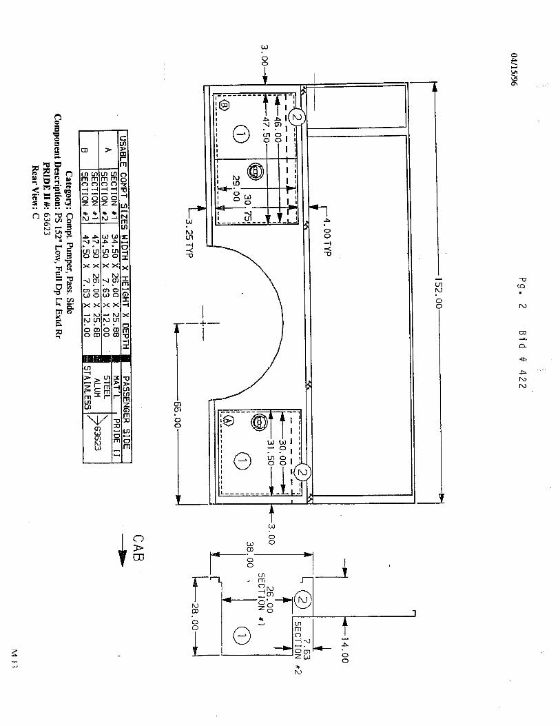


![PROCUREMENT OVERVIEW - Washington State Web view[Bidder Company Name] Proposal Option 2.docx (or .pdf) [Bidder Company Name] Cost Proposal Option 2.xlsx. ... either Microsoft Word](https://img.dokumen.tips/doc/110x75/5a90de297f8b9a085a8e76d1/procurement-overview-washington-state-web-viewbidder-company-name-proposal.jpg)