Embed Size (px)
Citation preview

13th World Conference on Earthquake Engineering Vancouver, B.C., Canada
August 1-6, 2004 Paper No. 3479
PROPOSAL OF RESPONSE CONTROLLED STRUCTURAL SYSTEM OF CONNECTED HIGH-RISE BUILDINGS WITH CONCENTRATED
DAMPERS AT BASE
Katsuhide MURAKAMI 1, Michio KEII2, Masato ISHII3, Nobutaka KASHIMOTO4 and Takayuki
TERAMOTO5
SUMMARY Structural control systems with dampers, which are placed within frames, are effective in preventing damage on a structure due to intense seismic actions. However, in the usual structural control systems with dampers, certain restrictions on architectural planning are inevitable as it is necessary to keep appropriate distribution of many dampers for providing effective deformation in them, in order to achieve excellent seismic performance by remarkable reduction of story drift. The authors propose a new structural control system with dampers for high-rise buildings where two different types of structures, one is a base isolated structure and another is an ordinary earthquake resistant structure, are connected to each other at the top story. In this new structural control system, it is not necessary to install dampers at typical floors and suited to the design of multifunctional high-rise buildings. Natural periods of each of two building structures, amount of the dampers in the isolation story, mass ratio of the base isolated structure, etc. are the important parameters in this new structural control system. A series of time-history seismic response analyses for various combinations of the parameters are carried out and it is concluded that this new structural control system can provide excellent seismic performance as the isolated story positively absorbs seismic input energy.
INTRODUCTION
1 Senior Engineer, NIKKEN SEKKEI Ltd., Japan. Email: [email protected] 2 General Manager, NIKKEN SEKKEI Ltd., Japan. Email: [email protected] 3 Senior Engineer, NIKKEN SEKKEI Ltd., Japan. 4 Engineer, NIKKEN SEKKEI Ltd., Japan. 5 Professor, SCIENCE UNIVERSITY OF TOKYO, Japan.

In the seismic design of high-rise buildings, the objective is generally to ensure that, in the event of major earthquakes, damage is not concentrated in specific stories by keeping uniform structural properties through all stories, and the main beams on each story yield to absorb the seismic energy within the range of deformation not exceeding ultimate lateral shear strength. In a major earthquake, however, the beams that support the vertical load of the building suffer damage. In base-isolated structures where the seismic input to the buildings is reduced, the structural frames remain elastic even in the event of major earthquakes, so the columns and beams supporting vertical loads suffer almost no damage. Seismic isolation stories are equipped with laminated rubber bearings that support the vertical load of the building but are capable of large deformation in the horizontal direction, as well as dampers that absorb seismic energy. This enables great reduction in the seismic force applied to the structure. In high-rise buildings, however, the wind load that act as a horizontal load in a certain direction exceeds the yield strength of the dampers in the seismic isolation story, making it difficult to ensure the elastic behavior of the building as a whole including the seismic isolation story. For this reason, a number of dampers that exceeds the number required to achieve the ideal seismic load reduction effect must be provided on the seismic isolation story to ensure the elastic behavior of the building as a whole. As this tendency is conspicuous in steel structures for which the building weight is low with respect to the projected area of building elevations, application of base isolation to such buildings tends to cause problems. Other methods for preventing damage to structures in the event of major earthquakes include passive response controlled structure systems, an effective structure in which dampers are placed within the frame to absorb the seismic load. However, in general passive response controlled structure systems, it is necessary to design the sections of beams and columns that support the vertical load as small as possible in order to produce effective deformation at the dampers, and many dampers are provided to absorb the seismic energy in order to reduce the story deformation of the building and achieve excellent seismic performance. For this reason, problems with vertical vibration tend to be produced over the permanent term. In addition, the positions of the dampers on each story impose major restrictions on architectural planning in order to ensure that the dampers function effectively. Accordingly, the authors believe that a structural system that can provide excellent seismic resisting performance for high-rise buildings without imposing major restrictions on the locations of the dampers on each story is required. This paper proposes a new structural system suitable for high-rise buildings in which two structures with different types of structural systems - one a base-isolated structure and the other an ordinary seismic resisting structure - are connected at the top. In this structural system, dampers that absorb seismic energy are provided in the seismic isolation story at the base of only one of the two structures. For this reason, it is not necessary to provide dampers on the ordinary floors of the buildings. Furthermore, time-history seismic response analysis is used to show that this structural system effectively absorbs seismic energy at the seismic isolation story in the base-isolated structure and therefore provides an effective method for seismic design.
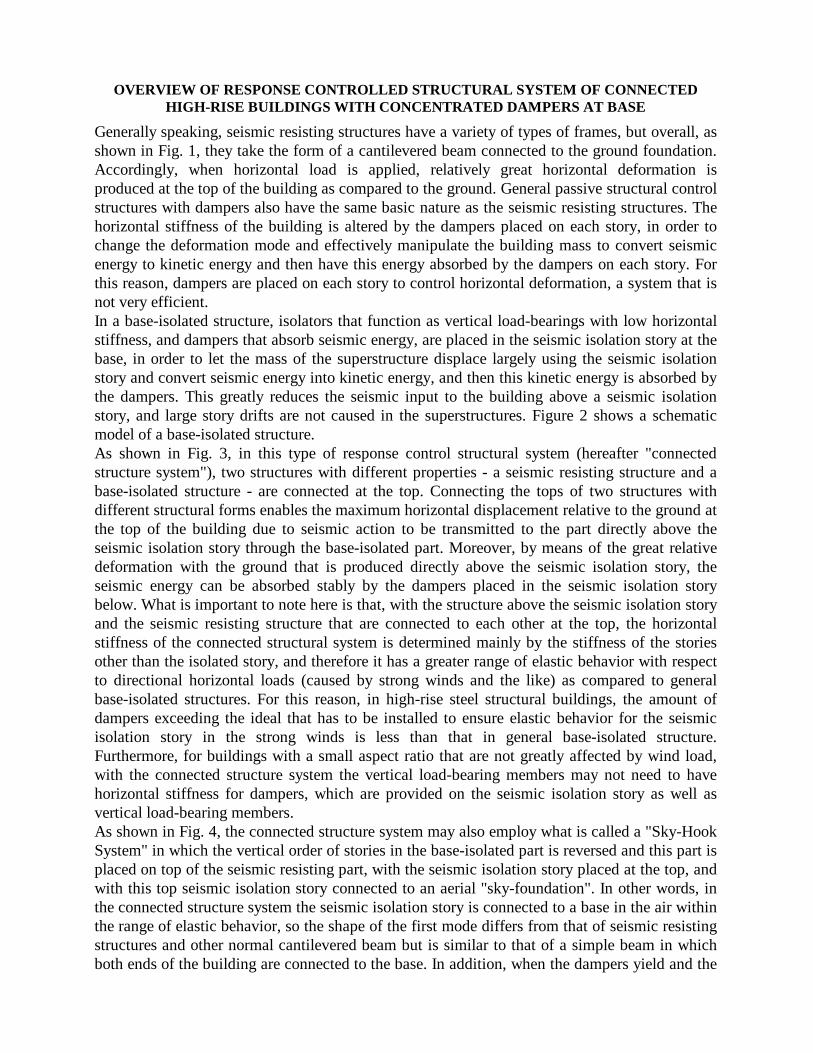
Generally speaking, seismic resisting structures have a variety of types of frames, but overall, as shown in Fig. 1, they take the form of a cantilevered beam connected to the ground foundation. Accordingly, when horizontal load is applied, relatively great horizontal deformation is produced at the top of the building as compared to the ground. General passive structural control structures with dampers also have the same basic nature as the seismic resisting structures. The horizontal stiffness of the building is altered by the dampers placed on each story, in order to change the deformation mode and effectively manipulate the building mass to convert seismic energy to kinetic energy and then have this energy absorbed by the dampers on each story. For this reason, dampers are placed on each story to control horizontal deformation, a system that is not very efficient. In a base-isolated structure, isolators that function as vertical load-bearings with low horizontal stiffness, and dampers that absorb seismic energy, are placed in the seismic isolation story at the base, in order to let the mass of the superstructure displace largely using the seismic isolation story and convert seismic energy into kinetic energy, and then this kinetic energy is absorbed by the dampers. This greatly reduces the seismic input to the building above a seismic isolation story, and large story drifts are not caused in the superstructures. Figure 2 shows a schematic model of a base-isolated structure. As shown in Fig. 3, in this type of response control structural system (hereafter "connected structure system"), two structures with different properties - a seismic resisting structure and a base-isolated structure - are connected at the top. Connecting the tops of two structures with different structural forms enables the maximum horizontal displacement relative to the ground at the top of the building due to seismic action to be transmitted to the part directly above the seismic isolation story through the base-isolated part. Moreover, by means of the great relative deformation with the ground that is produced directly above the seismic isolation story, the seismic energy can be absorbed stably by the dampers placed in the seismic isolation story below. What is important to note here is that, with the structure above the seismic isolation story and the seismic resisting structure that are connected to each other at the top, the horizontal stiffness of the connected structural system is determined mainly by the stiffness of the stories other than the isolated story, and therefore it has a greater range of elastic behavior with respect to directional horizontal loads (caused by strong winds and the like) as compared to general base-isolated structures. For this reason, in high-rise steel structural buildings, the amount of dampers exceeding the ideal that has to be installed to ensure elastic behavior for the seismic isolation story in the strong winds is less than that in general base-isolated structure. Furthermore, for buildings with a small aspect ratio that are not greatly affected by wind load, with the connected structure system the vertical load-bearing members may not need to have horizontal stiffness for dampers, which are provided on the seismic isolation story as well as vertical load-bearing members. As shown in Fig. 4, the connected structure system may also employ what is called a "Sky-Hook System" in which the vertical order of stories in the base-isolated part is reversed and this part is placed on top of the seismic resisting part, with the seismic isolation story placed at the top, and with this top seismic isolation story connected to an aerial "sky-foundation". In other words, in the connected structure system the seismic isolation story is connected to a base in the air within the range of elastic behavior, so the shape of the first mode differs from that of seismic resisting structures and other normal cantilevered beam but is similar to that of a simple beam in which both ends of the building are connected to the base. In addition, when the dampers yield and the
OVERVIEW OF RESPONSE CONTROLLED STRUCTURAL SYSTEM OF CONNECTED HIGH-RISE BUILDINGS WITH CONCENTRATED DAMPERS AT BASE

General seismic resisting/passive structural control structure
Seismicisolationstory
General base-isolatedStructure
Base-isolatedstructure
Seismic resistingstructure
Base-isolatedstructural part
Seismic resistingstructural part
Seismicisolationstory
Rigid
Seismicisolationstory
Base-isolatedstructural part
Seismic resistingstructural part
Seismicisolationstory
Base-isolatedstructural part
Seismic resistingstructural part
Rigid
Rigid
Seismicisolationstory
Fig. 1 Model of a general seismic resisting /passive structural control structure and first mode deformation for this structure
Fig. 2 Model of a general base-isolated structure and first mode deformation (with or without dampers) for this structure
Fig. 3 Model of a connected structure system (1)
Fig. 4 Model of a connected structure system (2)

Seismic isolation story Seismic isolation story
Movable bridge Movable bridge
Seismic isolation story
Type 1 Type 2 Type 3
Fig. 5 Building types using connected structure system
seismic isolation story sustains major deformation, the deformation shape of the first mode is thought to be a shape similar to that of ordinary seismic resisting structures and other cantilevered beam forms. Figure 5 shows a schematic of the shapes of buildings using the connected structure system. With the connected structure system, if the horizontal centers of gravity of the different structures are greatly misaligned, it is possible that torsional deformation in the horizontal direction may occur due to the behavior of the building as a whole when horizontal load is applied. Accordingly, it is thought best to create a shape that will produce as little horizontal torsional deformation as possible. A detailed study of this matter remains an issue for future consideration. VERIFICATION OF DAMPING EFFECTIVENESS BY MEANS OF VIBRATION RESPONSE ANALYSIS The connected structure system will be affected by the height of the buildings, the different natural periods in the two parts of structural system, the number of dampers in the seismic isolation story, the mass ratio of the base-isolated part and so on. Of these parameters, this paper focuses on the number of dampers in the seismic isolation story and the mass ratio of the base-isolated part. Time history seismic response analyses assuming a major earthquake were

conducted to study the effectiveness of the connected structure system in reducing seismic response.Figure 6 shows the structural model that was assumed for the purposes of the analysis. Outline of the model is described in the followings: • The model used in the study is a 20 mass points model: 10 mass points for the ten stories in
the model of the seismic resisting part, and 10 mass points for the model of the base-isolated part (comprising the first story as the seismic isolation story and nine stories above that). It is an one dimensional model unaffected by torsion.
• The mass of each story in the seismic resisting part is equal. The mass of each story in the base-isolated part is also equal, including the first story (ImF) that serves as the foundation.
• The mass of the stories in the connected structure system (the stories in the seismic resisting part plus the stories in the base-isolated part) is mi=620.6 tons. In other words, if the mass of a story in the seismic resisting part is Omi and the mass of a story in the base-isolated part is Imi, then
mi=Omi + Imj-1 (where m1=Om1 + ImF) (1)
Where i=1 – 10, j=1 - 9 Also, if the ratio of the mass of the base-isolated structural section to the mass of the entire connected structure system is Rm, then
Rm=(ΣImj + ImF)/ Σmi (2) Where i=1 – 10, j=1 - 9
• The model of the seismic resisting part is an elastic model with a stiffness distribution such
that the stiffness of each story OK1 is uniform, and so the natural period of the first mode, OT1 for 10 stories is two seconds. The assumed story height for the building taking into consideration the results of the response for the reference structure (to be discussed later) is 7.2 meters.
• The superstructure of the base-isolated part is an elastic model with a stiffness distribution such that the stiffness of each story IK1 is uniform, and so the natural period of the first mode, IT1 for 9 stories is two seconds. The assumed story height for the building is 7.2 meters.
• The vertical load-bearing members for the seismic isolation story of the base-isolated part are laminated natural rubber bearings. The elastic stiffness mKf of these bearings is set so the natural period mTf when the mass of the base-isolated structure model alone is converged to a single mass point is four seconds.
• The dampers for the seismic isolation story of the base-isolated structural section are hysteretic dampers with fully elasto-plastic restoring force characteristics. The initial stiffness of the dampers is set so the natural period mTs when the mass of the base-isolated structure alone is converged to a single mass point is 0.5 second. The dampers are assumed to have no stiffness after they yield. The yield strength of the dampers is evaluated using the weight of the entire building Σmig (where g=gravitational acceleration), with the ratio α's=mQy/Σmig (damper yield

( unit : sec )
strength/total building weight). • For the seismic resisting part, the internal damping of the structure was assumed to be directly
proportional to stiffness and was assumed to be Oh=0.02 for the fundamental natural period OT1. For the model of the upper structure of the base-isolated part as well, the internal damping of the structure was assumed to be directly proportional to stiffness and was assumed to be
Vibration mode 1st 2nd 3rd 4th 5th 6th
Standard seismic resisting structure
2.000 0.672 0.409 0.299 0.240 0.204
Without damper 4.320 0.907 0.477 0.328 0.254 0.211 Standard base-isolated structure With damper 1.862 0.626 0.382 0.280 0.225 0.193
Rm Vibration mode 1st 2nd 3rd 4th 5th 6th
Without damper 2.538 1.370 0.747 0.597 0.436 0.385 0.3
With damper 2.013 0.970 0.676 0.492 0.412 0.335
Without damper 2.929 1.275 0.784 0.578 0.447 0.378 0.5
With damper 2.023 0.966 0.680 0.490 0.414 0.334
Without damper 3.374 1.183 0.825 0.559 0.459 0.372
Connected structure system
0.7 With damper 2.032 0.962 0.683 0.487 0.416 0.332
Table 1 Natural periods for each model
Fig. 6 Response analysis model for 20 stories in a connected structure system
Rigid
oK10
oK9
oK8
oK7
oK6
oK5
oK4
oK3
oK2
oK1
om10
om9
om8
om7
om6
om5
om4
om3
om2
om1
im9
im8
im7
im6
im5
im4
im3
im2
im1
imF
iK9
iK8
iK7
iK6
iK5
iK4
iK3
iK2
iK1
mkf mks
Seismicisolationstory
Base-isolatedstructural part
Seismic resistingstructural part
im9
im8
im7
im6
im5
im4
im3
im2
im1
imF
iK9
iK8
iK7
iK6
iK5
iK4
iK3
iK2
iK1
om10
om9
om8
om7
om6
om5
om4
om3
om2
om1
oK9
oK8
oK7
oK6
oK5
oK4
oK3
oK2
oK1
oK10

Ih=0.02 for the fundamental natural period IT1. The seismic isolation story was assumed to have no internal damping.
• The seismic ground motion input for the study was an artificial design seismic wave that assumed a Level 2 earthquake motion (ART WAVE 456). This seismic wave has been prepared by setting the velocity response spectrum in the long period to Sv=125 cm/sec (h=0.02) and using the phase characteristics of the observed earthquake ground motion.
Table 1 shows the natural period for each structural model. Here the standard seismic resisting structure is a 10-story elastic model, with the total mass the same as that of the seismic resisting part in the connected structural model, with all stories having uniform mass and stiffness, and with the fundamental natural period equal to two seconds. The standard base-isolated structure is one with a total mass that is the same as the total mass of the base-isolated part in the connected structural model, with all stories in the base and superstructure having uniform mass, with all stories of the superstructure being elastic and having uniform stiffness, and with the fundamental natural period equal to two seconds. The seismic isolation story is provided with natural rubber bearings possessing elastic stiffness, such that the natural period is equivalent to four seconds when the mass of the base-isolated structure model alone is converged to a single mass point, as well as with hysteretic dampers possessing fully elasto-plastic restoring force characteristics, with initial stiffness such that the natural period is 0.5 second. Figures 7-1 through 7-4 show the first, second and third natural modes (βu) for the connected structure model. Figure 7-1 shows each part in the connected structural model when Rm=0.5; Figs. 7-2 through 7-4 show the status when Rm=0.3, 0.5 and 0.7, respectively, and when the order of stories in the base-isolated part is reversed and this part is placed on top of the seismic resisting part, with the seismic isolation story placed at the top. From these results, it can be seen that the first natural period is greater when the elastic stiffness of dampers is not taken into consideration (assuming a time at which the seismic isolation story sustains great deformation) than when the dampers exhibit elastic behavior. This value is related in particular to the ratio of the mass of the base-isolated part to total mass (Rm). As Rm increases, the natural period also increases and approaches the value of a general base-isolated structure. In addition, in the range within which the dampers in the seismic isolation story exhibit elastic behavior, the building is connected to an aerial "sky-foundation", so the first mode βu differs from that of a cantilevered beam, as in a general building, and becomes like the simple beam form that is connected to the ground on both ends of the building. When the dampers yield and the seismic isolation story sustains great deformation, the first mode βu becomes similar to the beam deformation distribution in which the base on the seismic resisting structural side is rigid and the seismic isolation story is supported by soft elastic supports, and the distribution approaches that of a cantilevered beam fixed at the ground as in a general building. Figures 8-1 through 8-5 show the results of vibration response analysis when Rm=0.5 and with the amount of dampers α's as a parameter. In Fig. 8-3, the story shear coefficient of each part is calculated as the ratio of story shear in each part to the weight of each part of the building supported by the structure at the story. From these results, the followings can be pointed out. • As α's increases, for both the seismic resisting part and the base-isolated part (with the
exception of the top), the response values for maximum story shear force, maximum story
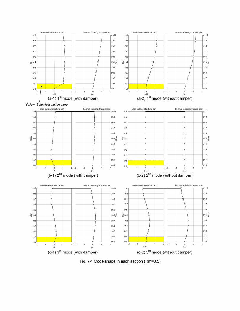
(a-1) 1st mode (with damper) (a-2) 1st mode (without damper) (b-1) 2nd mode (with damper) (b-2) 2nd mode (without damper) (c-1) 3rd mode (with damper) (c-2) 3rd mode (without damper)
Fig. 7-1 Mode shape in each section (Rm=0.5)
Base-isolated structural part
0
1
2
3
4
5
6
7
8
9
10
-2 -1 0 1 2β-U
Stor
y
im9
im8
im7
im6
im5
im3
im2
im1
imF
im0
im4
Seismic resisting structural part
1
2
3
4
5
6
7
8
9
10
11
-2 -1 0 1 2β -U
Stor
y
om10
om9
om8
om7
om6
om4
om3
om2
om1
om0
om5
Base-isolated structural part
0 1 2 3 4 5 6 7 8 9
10
-2 -1 0 1 2β -U
Stor
y
im9 im8 im7 im6 im5
im3 im2 im1 imF im0
im4
Seismic resisting structural part
1
2
3
4
5
6
7
8
9
10
11
-2 -1 0 1 2β -U
Stor
y om10
om9
om8
om7
om6
om4
om3
om2
om1
om0
om5
Base-isolated structural part
0
1
2
3
4
5
6
7
8
9
10
-2 -1 0 1 2
β -U
Sto
ry
im9
im8
im7
im6
im5
im3
im2
im1
imF
im0
im4
Seismic resisting structural part
1
2
3
4
5
6
7
8
9
10
11
-2 -1 0 1 2β -U
Stor
y
om10
om9
om8
om7
om6
om4
om3
om2
om1
om0
om5
Base-isolated structural part
0 1 2 3 4 5 6 7 8 9
10
-2 -1 0 1 2β -U
Stor
y
im9 im8 im7 im6 im5
im3 im2 im1 imF im0
im4
Seismic resisting structural part
1
2
3
4
5
6
7
8
9
10
11
-2 -1 0 1 2β -U
Stor
y
om10
om9
om8
om7
om6
om4
om3
om2
om1
om0
om5
Base-isolated structural part
0 1 2 3 4 5 6 7 8 9
10
-2 -1 0 1 2 β -U
Stor
y im9 im8 im7 im6 im5
im3 im2 im1 imF im0
im4
Seismic resisting structural part
1
2
3
4
5
6
7
8
9
10
11
-2 -1 0 1 2β -U
Stor
y
om10
om9
om8
om7
om6
om4
om3
om2
om1
om0
om5
Yellow: Seismic isolation story
Base-isolated structural part
0
1
2
3
5
6
7
8
9
10
-2 -1 0 1 2β -U
Stor
y
im9
im8
im7
im6
im5
im3
im2
im1
imF
im0
im4
Seismic resisting structural part
1
2
3
4
5
6
7
8
9
10
11
-2 -1 0 1 2β -U
Stor
y
om10
om9
om8
om7
om6
om4
om3
om2
om1
om0
om5

Fig.7-2 Mode shape (Rm=0.3) Fig.7-3 Mode shape (Rm=0.5) Fig.7-3 Mode shape (Rm=0.7)
shear force coefficient and maximum story drift decrease as compared to the standard seismic resisting structure. However, when a certain extreme value is reached, this tendency to decrease changes to a tendency to increase, and the value tends to be asymptotic of the response for the standard seismic resisting structure. In addition, the response for the standard base-isolated structure with dampers becomes the lower limit for each response, and it can be predicted that the response for the standard seismic resisting structure would become the upper limit. Accordingly, from this tendency, it was confirmed that the connected structure system is effective in reducing seismic response for the building as a whole.
• In the seismic isolated part of the connected structure, as the amount of dampers increases, the response for the maximum story drift for the building tends to decrease in the upper stories and tends to increase in the lower stories. In other words, if there little amount of dampers, the horizontal displacement distribution in the building is close to the beam deformation distribution in which the base on the seismic resisting structure side is rigid and the seismic isolation story section is supported by soft elastic supports. As the number of dampers increases, the deformation distribution approaches a simple beam deformation distribution in which both the base on the seismic resisting structure side and the base on the seismic isolation story side are rigid.
• The response for maximum top deformation of the connected structural model decreases as the value for α's increases. However, when a certain extreme value is reached, this tendency to decrease changes to a tendency to increase, and the value tends to be asymptotic of the response for the standard seismic resisting structure. In addition, the response for the standard base-isolated structure becomes the lower limit for the decrease in maximum top deformation for the model.
• In the seismic isolated part of the connected structure model, as the value for α's increases, the response for the upper structural section tends to decrease and the response for the middle stories tends to increase. In addition, the response for the standard seismic resisting structure becomes the upper limit for the response for the superstructure. The response for the standard base-isolated structure is thought to be close to the lower limit for the response.
1 2 3 4 5 6 7 8 9 10 11 12 13 14 15 16 17 18 19 20 21 22
-2 -1 0 1 2 β -U
Stor
y im0 imF im1 im2 im3 im4 im5 im6 im7 im8 im9
om10 om9 om8 om7 om6 om5 om4 om3 om2 om1 om0 1
23456789
10111213141516171819202122
-2 -1 0 1 2
β-U
Stor
y
Without damper 1stWithout damper 2ndWithout damper 3rdWith damper 1stWith damper 2ndWith damper 3rd
im0imFim1im2im3im4im5im6im7im8im9
om10om9om8om7om6om5om4om3om2om1om0 1
23456789
10111213141516171819202122
-2 -1 0 1 2
β -U
Stor
y
im0imFim1im2im3im4im5im6im7im8im9
om10om9om8om7om6om5om4om3om2om1om0
Yellow: Seismic isolation story

Where * S.S.R.S: Standard Seismic Resisting Structure, S.B.I.S: Standard Base-isolated Structure * imF: Seismic Isolation Story
Fig. 8-1 Maximum Story Shear Force in each section (Rm=0.5) Fig.8-2 Maximum Story Fig.8-3 Maximum Story Shear Fig.8-4 Story Height / Maximum Shear Force (Rm=0.5) Force Coefficient (Rm=0.5) Story Drift (Rm=0.5) (a) Top story (b) seismic isolation story
Fig.8-5 Maximum Deformation of Top and Seismic Isolation Story (Rm=0.5)
1 2 3 4 5 6 7 8 9 10
11 12 13 14 15 16 17 18 19 20 21
0 50000 100000 150000 200000 Maximum Story Shear Force (kN)
Stor
y
im0 imF im1 im2 im3 im4 im5 im6 im7 im8
im9=om10 om9
om8 om7 om6 om5 om4 om3 om2 om1 om0 1
2 3 4 5 6 7 8 9
10 11 12 13 14 15 16 17 18 19 20 21
0 0.5 1 1.5 2 2.5 3
Maximum Story Shear Force Coefficient
Stor
y
im0 imF im1 im2 im3 im4 im5 im6 im7 im8
im9=om10 om9
om8 om7 om6 om5 om4 om3 om2 om1 om0
Base-isolated structural part
0 1 2 3 4 5 6 7 8 9
10
0 50000 100000 150000 200000Shear Force Qi (kN)
Sto
ry
S.S.R.SS.B.I.S α's = 0α's = 0.01α's = 0.02α's = 0.03α's = 0.04α's = 0.05α's = 0.06α's =
im8 im7 im6 im5
im3 im2 im1
im0
im4
imF
im9
α's = 0.00α's = 0.01α's = 0.02α's = 0.03α's = 0.04α's = 0.05α's = 0.06α's = infinity
S.B.I.S α's = 0.03
Seismic resisting structural part
1 2 3 4 5 6 7 8 9 10 11
0 50000 100000 150000 200000 Shear Force Qi (kN)
Sto
ry
om9 om8 om7 om6
om4 om3 om2
om0
om5
om1
om10
α's
Max
imum
Def
orm
atio
n of
Sei
smic
Isol
atio
n St
ory
(cm
)
0
20
40
60
80
100
120
140
0 0.01 0.02 0.03 0.04 0.05 0.06 0.07
Standard base-isolated structure
0 20 40 60 80
100 120 140
0 0.01 0.02 0.03 0.04 0.05 0.06 0.07α's
Max
imum
Top
Def
orm
atio
n (c
m)
Standard seismic resisting structure
Standard base-isolated structure
Yellow: Seismic isolation story
Yellow: Seismic isolation story
123456789
101112131415161718192021
0 100 200 300 400 500 600 700 800
Story Height / Maximum Story Deformation
S.S.R.S
Μ
α's = 0
α's = 0.01
α's = 0.02
α's = 0.03
α's = 0.04
α's = 0.05
α's = 0.06
α's =
im0imFim1
im2im3im4im5im6
im7im8
im9=om1
om9om8
om7om6om5om4om3
om2om1om0
α's = 0.00
α's = 0.01
α's = 0.02
α's = 0.03
α's = 0.04
α's = 0.05
α's = 0.06
α's = infinity
S.B.I.Sα's = 0.03
Stor
y

Where * S.S.R.S: Standard Seismic Resisting Structure, S.B.I.S: Standard Base-isolated Structure * imF: Seismic Isolation Story
Fig. 9-1 Maximum Story Shear Force in each section (Rm=0.3) Fig.9-2 Maximum Story Fig.9-3 Maximum Story Shear Fig.9-4 Story Height / Maximum Shear Force (Rm=0.3) Force Coefficient (Rm=0.3) Story Drift (Rm=0.3) (a) Top story (b) seismic isolation story
Fig.9-5 Maximum Deformation of Top and Seismic Isolation Story (Rm=0.3)
Base-isolated structural part
0 1 2 3 4 5 6 7 8 9
10
0 50000 100000 150000 200000Shear Force Qi (kN)
Sto
ry
S.S.R.SS.B.I.S α's = 0.00 α's = 0.01 α's = 0.02 α's = 0.03 α's = 0.04 α's = 0.05 α's = 0.06 α's =
im8 im7 im6 im5
im3 im2 im1
im0
im4
imF
im9
α's = 0.00α's = 0.01α's = 0.02α's = 0.03α's = 0.04α's = 0.05α's = 0.06α's = infinity
S.B.I.S α's = 0.03
1 2 3 4 5 6 7 8 9 10 11
0 50000 100000 150000 200000 Shear Force Qi (kN)
Sto
ry
om9
om8
om7
om6
om4
om3
om2
om0
om5
om1
om10
1 2 3 4 5 6 7 8 9 10
11 12 13 14 15 16 17 18 19 20 21
0 50000 100000 150000 200000 Maximum Story Shear Force (kN)
Stor
y
im0 imF im1 im2 im3 im4 im5 im6 im7 im8
im9=om10 om9
om8 om7 om6 om5 om4 om3 om2 om1 om0 1
2 3 4 5 6 7 8 9 10
11 12 13 14 15 16 17 18 19 20 21
0.000 0.500 1.000 1.500 2.000 2.500 3.000
Maximum Story Shear Force Coefficient
Stor
y
im0 imF im1 im2 im3 im4 im5 im6 im7 im8
im9=om10 om9
om8 om7 om6 om5 om4 om3 om2 om1 om0
Seismic resisting structural part
0
20
40
60
80
100
120
140
0 0.01 0.02 0.03 0.04 0.05 0.06 0.07 α's
Max
imum
Def
orm
atio
n of
Sei
smic
Isol
atio
n St
ory
(cm
)
Standard base-isolated structure
0 20 40 60 80
100 120 140
0 0.01 0.02 0.03 0.04 0.05 0.06 0.07α's
Max
imum
Top
Def
orm
atio
n (c
m)
Standard seismic resisting structure
Standard base-isolated structure
Yellow: Seismic isolation story
Yellow: Seismic isolation story
Story Height / Maximum Story Deformation
im9=om10
123456789
101112131415161718192021
0 100 200 300 400 500 600 700 800
S.S.R.S
Μ
α's = 0
α's = 0.01
α's = 0.02
α's = 0.03
α's = 0.04
α's = 0.05
α's = 0.06
α's =
im0imFim1
im2im3im4im5im6
im7im8
om9om8
om7om6om5om4om3om2om1
om0
α's = 0.00
α's = 0.01
α's = 0.02
α's = 0.03
α's = 0.04
α's = 0.05
α's = 0.06
α's = infinity
S.B.I.Sα's = 0.03
Stor
y

Where * S.S.R.S: Standard Seismic Resisting Structure, S.B.I.S: Standard Base-isolated Structure * imF: Seismic Isolation Story
Fig. 10-1 Maximum Story Shear Force in each section (Rm=0.7) Fig.10-2 Maximum Story Fig.10-3 Maximum Story Shear Fig.10-4 Story Height / Maximum Shear Force (Rm=0.7) Force Coefficient (Rm=0.7) Story Drift (Rm=0.7) (a) Top story (b) seismic isolation story
Fig.10-5 Maximum Deformation of Top and Seismic Isolation Story (Rm=0.7)
1 2 3 4 5 6 7 8 9
10 11 12 13 14 15 16 17 18 19 20 21
0 50000 100000 150000 200000 Maximum Story Shear Force (kN)
Stor
y
im0 imF im1 im2 im3 im4 im5 im6 im7 im8
im9=om10 om9 om8 om7 om6 om5 om4 om3 om2 om1 om0 1
2 3 4 5 6 7 8 9 10
11 12 13 14 15 16 17 18 19 20 21
0.000 0.500 1.000 1.500 2.000 2.500 3.000Maximum Story Shear Force Coefficient
Stor
y
im0 imF im1 im2 im3 im4 im5 im6 im7 im8
im9=om10 om9 om8 om7 om6 om5 om4 om3 om2 om1 om0
Base-isolated structural part
0 1 2 3 4 5 6 7 8 9
10
0 50000 100000 150000 200000Shear Force Qi (kN)
Sto
ry
im8 im7 im6 im5
im3 im2 im1
im0
im4
imF
im9
1 2 3 4 5 6 7 8 9 10 11
0 50000 100000 150000 200000 Shear Force Qi (kN)
Sto
ry
om9 om8 om7 om6
om4 om3 om2
om0
om5
om1
om10
S.S.R.S S.B.I.S α's = 0.00 α's = 0.01 α's = 0.02 α's = 0.03 α's = 0.04 α's = 0.05 α's = 0.06 α's =
α'sα's = 0.01 α's = 0.02 α's = 0.03 α's = 0.04 α's = 0.05 α's = 0.06 α's = infinity
S.B.I.S α ' s = 0.03 = 0.00
Seismic resisting structural part
0 20 40 60 80
100 120 140
0 0.01 0.02 0.03 0.04 0.05 0.06 0.07α's
Max
imum
Top
Def
orm
atio
n (c
m)
Standard seismic resisting structure
Standard base-isolated structure
0
20
40
60
80
100
120
140
0 0.01 0.02 0.03 0.04 0.05 0.06 0.07α's
Max
imum
Def
orm
atio
n of
Sei
smic
Isol
atio
n St
ory
(cm
)
Standard base-isolated structure
Yellow: Seismic isolation story
Yellow: Seismic isolation story
123456789
101112131415161718192021
0 100 200 300 400 500 600 700 800
S.S.R.S
��α's=0.03
α's = 0
α's = 0.01
α's = 0.02
α's = 0.03
α's = 0.04
α's = 0.05
α's = 0.06
α's = ∞
im0imFim1
im2im3im4im5im6
im7im8
im9=om1
om9om8
om7om6om5om4om3
om2om1om0
α's = 0.00
α's = 0.01
α's = 0.02
α's = 0.03
α's = 0.04
α's = 0.05
α's = 0.06
α's = infinity
S.B.I.Sα's = 0.03
Stor
y
Story Height / Maximum Story Deformation

• The response for deformation of the seismic isolation story in the connected structural model decreases as the value for α's increases. This is the same trend as for the standard base-isolated structure.
Figures 9-1 through 9-5 and Figs. 10-1 through 10-5 show the results of seismic response analyses with Rm=0.3 and 0.7, respectively, and with the amount of dampers α's as a parameter. The method of calculating the response for maximum story shear force coefficient for each part connected at the top story is same as that prescribed for Fig. 8-3. From these results, the followings can be pointed out. • As when Rm=0.5, the effectiveness of the connected structural system in reducing overall
seismic response was confirmed for the other mass ratios as well. In particular, the larger the mass ratio Rm is, the greater the effectiveness in reducing the seismic force applied to the building as a whole becomes. It can be seen that this tendency is particularly noteworthy for the seismic isolated part in the connected structure system.
• When the number of dampers α's on the seismic isolation story is small, it was found that the greater the mass ratio Rm becomes, the greater also becomes the tendency for top deformation in the connected structural model to be dependent on seismic isolation story deformation. For this reason, there is a tendency for the maximum story drift in the seismic isolated part to be small but for the maximum story drift in the seismic resisting part to be large. This tendency is particularly noteworthy when Rm=0.7. However, it can be seen that this tendency is lessened as the amount of dampers increases.
CONCLUSION
In this paper, the authors have proposed a new structural system suitable for a high-rise building in which two buildings with different structures - one a base-isolated structure and the other a normal seismic resisting structure - are connected at the top. The following points were learned: • Within a limited range, the connected structure system is effective in reducing the seismic
response of the building as a whole, and has excellent performance in seismic design. • The response values for story shear force, story drift and top displacement obtained with the
connected structural model decreases as the value for α's, the amount of dampers in the seismic isolation story, is increased. However, when a certain extreme value is reached, this tendency to decrease changes to a tendency to increase, and the value is asymptotic of the response for the standard seismic resisting structure.
REFERENCES
1. Architectural Institute of Japan(2001), “Recommendation for the Design of Base Isolated Buildings
“ 2. H. Kitamura, T. Yamane, K. Murakami and T. Teramoto(1990),”Artificial earthquakes with the
phase properties of recorded motions”, Summaries of Technical Papers, AIJ, pp287-290