Embed Size (px)
Citation preview

CNPP Service Éditions [email protected]
CEA 4001-2013 – Sprinklers Systems – Inquiry on amendments 2016 (February) 1/67
This document brings together all the amendments or modifications to be made to the CEA 4001-2013 proposed by the expert group EG4. Thank you for reviewing each of them by using the table at the end of this document. All comments and suggestions will be studied by GEI4 and adjustments will be done where appropriate.
PROPOSAL n° 1 – Modification of Chapter 1
Chapter 1: Checking of the definition of “distribution pipe” and “distribution pipe spur”
Replace “distribution pipe spur” by “distribution pipe” in figure F.1.3a, FHe, FHf and FHj and in annex D.3.3. Delete the definition of distribution pipe spur and modify definitions of distribution pipe as follow:
distribution pipe A pipe feeding either a range pipe. directly or a single sprinkler on a non-terminal range pipe more than 0.3m long.
distribution pipe spur A distribution pipe from a main distribution pipe, to a terminal branched pipe array.

CEA 4001-2013 – Sprinklers Systems – Inquiry on amendments 2016 (February) 2/67
PROPOSAL n° 2 – Modification of Chapter 8
Chapter 8: the Name of the water supply is not consistent within the chapter; choice of water supply and type of water supply Modify title of chapter 8 and title of §8.6 as follow:
8 CHOICE OF WATER SUPPLY TYPE OF WATER SUPPLY
8.6 Type of water supply Choice of water supply
(The content will be modify accordingly)
CEA 4001-2013 – Sprinklers Systems – Inquiry on amendments 2016 (February) 3/67
PROPOSAL n° 3 – Modification of Chapter 9
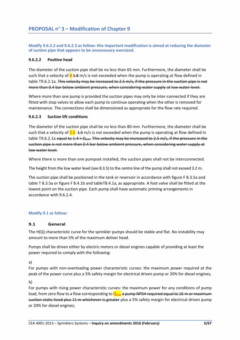
Modify 9.6.2.2 and 9.6.2.3 as follow: this important modification is aimed at reducing the diameter of suction pipe that appears to be unnecessary oversized.
9.6.2.2 Positive head
The diameter of the suction pipe shall be no less than 65 mm. Furthermore, the diameter shall be
such that a velocity of 4 1.8 m/s is not exceeded when the pump is operating at flow defined in
table T9.6.2.1a. This velocity may be increased to 2.5 m/s, if the pressure in the suction pipe is not
more than 0.4 bar below ambient pressure, when considering water supply at low water level.
Where more than one pump is provided the suction pipes may only be inter-connected if they are
fitted with stop valves to allow each pump to continue operating when the other is removed for
maintenance. The connections shall be dimensioned as appropriate for the flow rate required.
9.6.2.3 Suction lift conditions
The diameter of the suction pipe shall be no less than 80 mm. Furthermore, the diameter shall be
such that a velocity of 2.5 1.5 m/s is not exceeded when the pump is operating at flow defined in
table T9.6.2.1a equal to 1.4 × Q100. This velocity may be increased to 2.5 m/s, if the pressure in the
suction pipe is not more than 0.4 bar below ambient pressure, when considering water supply at
low water level.
Where there is more than one pumpset installed, the suction pipes shall not be interconnected.
The height from the low water level (see 8.3.5) to the centre line of the pump shall not exceed 3.2 m.
The suction pipe shall be positioned in the tank or reservoir in accordance with figure F 8.3.5a and
table T 8.3.5a or figure F 8.4.1b and tableT8.4.1a, as appropriate. A foot valve shall be fitted at the
lowest point on the suction pipe. Each pump shall have automatic priming arrangements in
accordance with 9.6.2.4.
Modify 9.1 as follow:
9.1 General
The H(Q) characteristic curve for the sprinkler pumps should be stable and flat. No instability may
amount to more than 5% of the maximum deliver head.
Pumps shall be driven either by electric motors or diesel engines capable of providing at least the
power required to comply with the following:
a)
For pumps with non-overloading power characteristic curves: the maximum power required at the
peak of the power curve plus a 5% safety margin for electrical driven pump or 20% for diesel engines;
b)
For pumps with rising power characteristic curves: the maximum power for any conditions of pump
load, from zero flow to a flow corresponding to Qmax a pump NPSH required equal to 16 m or maximum
suction static head plus 11 m whichever is greater plus a 5% safety margin for electrical driven pump
or 20% for diesel engines;

CEA 4001-2013 – Sprinklers Systems – Inquiry on amendments 2016 (February) 4/67
The coupling between the driver and the pump of horizontal pumpsets shall be of a type which
ensures that either can be removed independently and in such a way that pump internals can be
inspected or replaced without affecting suction or discharge piping. End suction pumps shall be of
the “back pull-out” type.
Pipework shall be supported independently of the pump.
PROPOSAL n° 4 – Modification of Chapter 10
Chapter 10.4.4: the requirements within this chapter needed to be updated in order to redefine
the different type of PRE-ACTION system.
The table below is not part of the proposal but is a support to understand the proposal.
Preaction type
Short description name Area of operation
Size of the system
Maximum Water delivery time at remote test valve
Type A1 If failure of detection , works as dry
Single interlock with fail safe mode
No increase of area of operation
Max 500 Max 60 seconds for HH and 90 sec for OH and LH
Type A2 No detection, no water even if sprinkler activates
Single interlock No increase of area of operation
Max 500 Max 60 seconds for HH and 90 sec for OH and LH
Type B Either activation of detection or activation of spk will activate alarm valve
Primed Single interlock
No increase of area of operation
Max 500 Max 60 seconds for HH and 90 sec for OH and LH
Type C Both activation of detection and activation of spk are required to activate alarm valve. Either one alone will not activate the valve
Double interlock Increase the area of operation by 25%
Max 500 Max 60 seconds for HH and 90 sec for OH and LH
Modify chapter 10.4 as follow: 10.4 Pre-action installations 10.4.1 General Pre-action installations are divided into two 4 types: It is required that the pre-action valve is equipped with a device that allows manual activation independently from any detection system. 10.4.1.1 Pre-action installation Type A1: Single interlock with fail safe mode
In the event of a fire detection fault, the pre-action installation shall operate as a dry pipe installation. This is a dry pipe system filled with air or inert gas in which the control valve set is activated by an automatic fire detection system but not by the operation of the sprinklers. In the event of a fire detection system goes into fault mode, the pre-action installation shall operate as a dry pipe installation. The air/inert gas pressure in the installation shall be monitored at all times. Consideration shall be given to fit a manually operated valve in an appropriate position to enable the pre-action valve to be activated in an emergency.

CEA 4001-2013 – Sprinklers Systems – Inquiry on amendments 2016 (February) 5/67
NOTE : type A1 pre-action installations should only be installed in areas where considerable damage could occur if there were an accidental discharge of water. 10.4.1.2 Pre-action installation Type A2: Single interlock This is a system filled with air or inert gas in which the control valve set is activated by an automatic fire detection system but not by the operation of the sprinkler. In the event of a fire detection system fault or failure, the pre-action installation may not operate automatically. The air/inert gas pressure in the installation shall be monitored at all times. 10.4.1.32 Pre-action installation Type B : Primed Single interlock This is an otherwise normal dry pipe system in which the control valve set is opened either by an automatic fire detection system or by the operation of the sprinklers. Independently of the response of the detectors, a pressure drop in the pipework causes the opening of the alarm valve. NOTE : type B pre-action installations may be installed wherever a dry pipe system is called for and the spread of fire is expected to be rapid, e.g. in high-rack storage. They may also be used instead of ordinary dry pipe systems with or without an accelerator or exhauster. 10.4.1.4 Pre-action installation Type C : Double interlock This is an otherwise normal dry pipe system in which the control valve set is opened by both activation of detection and the operation of the sprinkler. Either one alone will not activate automatically the valve. NOTE : type C pre-action installations should be installed in areas where considerable damage could occur if there were an accidental flooding of pipework. Typical application is in-rack protection in cold warehouses (deep freezer). 10.4.2 Sprinkler orientation In Type A installations All sprinklers in a pre-action installation shall be fitted in the upright position, except where dry pendent or horizontal sidewall sprinklers are used. or, only in a frost proof building, in the up-right or pendent position. In Type B installations, sprinklers shall be installed in the upright position. Note: Pendent position may be used in a building where there is no risk of frost, if accepted by authority. In such a case consideration shall be given to limit the size of the system. 10.4.3 Automatic detection system The detection system shall be installed in all rooms and compartments protected by the pre-action sprinkler system and shall comply with the relevant parts of EN54 CEA 4040 or equivalent and the components shall comply with relevant part of EN 54.. 10.4.4 Size of installations The number of sprinklers to be controlled by a pre-action type A alarm valve shall not exceed 500. 10.4.5 water delivery time The maximum water delivery time as measured at the remote test valve shall be limited to 60 seconds for HH and 90 sec for OH and LH. Note : For type A1, A2 and B, this is aimed to ensure that the system will effectively react similar as a wet system. For type C, this is aimed to ensure that the water delivery time corresponds to the requirement of a dry system.

CEA 4001-2013 – Sprinklers Systems – Inquiry on amendments 2016 (February) 6/67
Storage methods Maximum permitted storage height (m) (See note 1)
Minimum design density
Area of operation (wet or pre- action system
type A1, A2 or B (See note 2)
category I category II category III category IV mm/min m²
ST1 free standing or block
stacking
5,3 6,5 7,6
4,1 5,0 5,9 6,7 7,5
2,9 3,5 4,1 4,7 5,2
1,6 2,0 2,3 2,7 3,0
7,5 10,0 12,5 15,0 17,5
260
5,7 6,3 6,7 7,2
3,3 3,6 3,8 4,1 4,4
20,0 22,5 25,0 27,5 30,0
300 ST2
post pallets in single rows and ST4
Palletised racks (See note 3)
4,7 5,7 6,8
3,4 4,2 5,0 5,6 6,0
2,2 2,6 3,2 3,7 4,1
1,6 2,0 2,3 2,7 3,0
7,5 10,0 12,5 15,0 17,5
260
4,4 4,7 5,3 5,7 6,0
3,3 3,6 3,8 4,1 4,4
20,0 22,5 25,0 27,5 30,0
300
ST3 post or box pallets in multiple rows and
ST5/ST6 solid or slatted shelves
4,7 5,7
3,4 4,2 5,0
2,2 2,6 3,2
1,6 2,0 2,3 2,7 3,0
7,5 10,0 12,5 15,0 17,5
260
NOTE 1: the vertical distance from the floor to the sprinkler deflectors, minus 1m or the highest value shown in the table, whichever is the lower. NOTE 2: dry, and alternate systems should be avoided on High Hazard storages especially with the more combustible products (the higher categories) and the higher storages. Should it nonetheless be Where a pre-action type C, a dry or alternate system is installed, the area of operation shall be increased by 25 %. Note 3: for double row rack storage (ST4) exceeding 3,2m in height, longitudinal flue space no less than 0,15m shall be permanently maintaine from floor to top of storage.
Modify table T6.1a as follow: Table T 6.1a: Design density and area of operation for LH, OH and HHP
Hazard class Design density (minimum) mm/min
Area of operation m²
Wet or pre-action type A1, A2 or B Dry, pre-action type C or alternate
LH 2,25 84 not allowed - use OH1
OH1 5,0 72 90
OH2 5,0 144 180
OH3 5,0 216 270
OH4 5,0 360 not allowed - use HHP1
HHP1 7,5 260 325
HHP2 10,0 260 325
HHP3 12,5 260 325
HHP4 Special consideration apply
Modify table T6.2.2a as follow: Table T 6.2.2a: Design criteria for HHS with roof or ceiling protection only

CEA 4001-2013 – Sprinklers Systems – Inquiry on amendments 2016 (February) 7/67
Modify table T6.2.3.2a as follow. Table T 6.2.3.2a: Design criteria for roof sprinklers with in-rack protection
Storage methods Maximum permitted storage height above highest level of
intermediate sprinklers (1)
M
Minimum design density
mm/min
Area of operation
(wet or pre- action system
(2)
m² category I category II category III category IV
ST4 palletized rack 3,5 3,5 2,2 2,6 3,2 3,5
1,6 2,0 2,3 2,7
7,5 10,0 12,5 15,0
260
ST5 and ST6 solid or slatted shelves
4,7 5,7
3,4 4,2 5,0
2,2 2,6 3,2
1,6 2,0 2,3 2,7
3,0
7,5 10,0 12,5 15,0
17,5
260
NOTE 1: the vertical distance from the highest level of in-rack sprinklers to the roof or ceiling sprinklers, minus1m. NOTE 2: dry, and alternate systems should be avoided on High Hazard storages especially with the more combustible products (the higher categories) and the higher storages. Should it nonetheless be Where a dry, pre-action type C or alternate system is installed, the area of operation shall be increased by 25 %.
Modify: Table T8.3.2.1a and Table T8.3.4a as follow Table T 8.3.2.1a: Minimum water volume for precalculated LH and OH systems
Group Height h of the highest sprinkler above the lowest
sprinkler (See note 1)
Minimum water volume m3
LH - Wet or pre-action type A1, A2 or B h ≤ 15 15< h ≤ 30 30 < h ≤ 45
9 10 11
OH1 - Wet or pre-action type A1, A2 or B h ≤ 15 15 < h ≤ 30 30 < h ≤ 45
55 70 80
OH1 - Dry, alternate or pre-action type C OH2 - Wet or pre-action type A1, A2 or B
h ≤ 15 15 < h ≤ 30 30 < h ≤ 45
105 125 140
OH2 - Dry, alternate or pre-action type C OH3 - Wet or pre-action type A1, A2 or B
h ≤ 15 15 < h ≤ 30 30 < h 45
135 160 185
OH3 - Dry, alternate or pre-action type C OH4 - Wet or pre-action type A1, A2 or B
h ≤ 15 15 < h ≤ 30 30 < h ≤ 45
160 185 200
OH4 - Dry, alternate or pre-action type C Use HH protection
NOTE 1: Excluding sprinklers in the sprinkler valve room.

CEA 4001-2013 – Sprinklers Systems – Inquiry on amendments 2016 (February) 8/67
Table T 8.3.4a: Minimum capacity of reduced capacity tanks
Hazard Class Minimum capacity m3
LH - Wet or pre-action type A1, A2 or B 5
OH1 - Wet or pre-action type A1, A2 or B 10
OH1 – Dry, alternate or pre-action type C OH2 - Wet or pre-action type A1, A2 or B
20
OH2 - Dry, alternate or pre-action type C OH3 - Wet or pre-action type A1, A2 or B
30
OH3 - Dry, alternate or pre-action type C OH4 - Wet or pre-action type A1, A2 or B
50
HHP and HHS 70, but in no case less than 10% of the full capacity
Modify Table T 9.7.2a as follow
Table T 9.7.2a: Minimum pump characteristics for LH and OH (pre-calculated systems)
Hazard class Sprinkler height h
above the control valve
set(s) m
Nominal data Characteristic
Pressure bar
Flow l/min
Pressure bar
Flow l/min
Pressure bar
Flow l/min
LH wet or pre- action type A1, A2 or B
h ≤ 15 15 < h ≤ 30 30 < h ≤ 45
1.5 1.8 2.3
300 340 375
3.7 5.2 6.7
225 225 225
- - -
- - -
OH1 wet or pre-action type A1, A2 or B
h ≤ 15 15 < h ≤ 30 30 < h ≤ 45
1.2 1.9 2.7
900 1 150 1 360
2.2 3.7 5.2
540 540 540
2.5 4.0 5.5
375 375 375
OH1 dry, alternate or pre-action type C OH2 wet or pre-action type A1, A2 or B
h ≤ 15 15 < h ≤ 30 30 < h ≤ 45
1.4 2.0 2.6
1 750 2 050 2 350
2.5 4.0 5.5
1 000 1 000 1 000
2.9 4.4 5.9
725 725 725
OH2 dry, alternate or pre-action type C OH3 wet or pre-action type A1, A2 or B
h ≤ 15 15 < h ≤ 30 30 < h ≤ 45
1.4 2.0 2.5
2 250 2 700 3 100
2.9 4.4 5.9
1 350 1 350 1 350
3.2 4.7 6.2
1 100 1 100 1 100

CEA 4001-2013 – Sprinklers Systems – Inquiry on amendments 2016 (February) 9/67
OH3 dry, alternate or pre-action type C OH4 wet or pre-action type A1, A2 or B
h ≤ 15 15 < h ≤ 30 30 < h ≤ 45
1.9 2.4 3.0
2 650 3 050 3 350
3.0 4.5 6.0
2 100 2 100 2 100
3.5 5.0 6.5
1 800 1 800 1 800
NOTE 1: The pressures shown are as measured at the control valve set(s) NOTE 2: In the case of buildings which exceed the heights shown, it shall be proved that the pump characteristics are adequate for supplying the flows and pressures specified in 6.3.1.
Modify Table T 10.1.1a as follow Table T 10.1.1a: Maximum number of sprinklers per installation - wet pipe and pre-action installations
Hazard class Maximum number of sprinklers
LH 500
OH, including any LH sprinkler 1 000, except as allowed in Annexes D and F
HH, including any OH and LH sprinklers 1 000
Modify Table K6.1a as follow
Table T K.6.1a: Non-woven synthetic fabric: design criteria with roof or ceiling protection only
Storage methods
Maximum storage height
(see note 1)
Minimum design density mm/min
Area of operation (wet or pre-action system (see note 2))
m2
ST1 Free standing or block stacking
1.6 2.0 2.3 2.7
10.0 12.5 15.0 17.5
260
3.0 3.3 3.6 3.8 4.1
20.0 22.5 25.0 27.5 30.0
300
NOTE 1: the vertical distance from the floor to the sprinkler deflectors, minus 1 m, or the highest value shown in the table, whichever is the lower. NOTE 2: dry, alternate or pre-action type C installations should be avoided.
Modify Definition as follow
Installation, pre-action
One of types of dry Installation in which the alarm valve can or must be opened by an independent fire
detection system in the protected area. (see §10.4.1)

CEA 4001-2013 – Sprinklers Systems – Inquiry on amendments 2016 (February) 10/67
Modify annex I as follow
j) pre-action alarm valve assemblies Type A1;
k) pre-action alarm valve assemblies Type A2;
l) pre-action alarm valve assemblies Type B.
m) pre-action alarm valve assemblies Type C.
PROPOSAL n° 5 – Modification of Chapter 11
Modify 11.5 as follow
11.5 Intermediate sprinklers in High Hazard occupancies
11.5.1 General
Sprinklers protecting row racks shall be positioned in the longitudinal flue spaces, preferably in the
intersection with the transverse flue (see Figures F 11.5.1a and F 11.5.1b).
Whenever any rack or structural steelwork is likely to interfere significantly with the water discharge
from the sprinklers, additional sprinklers shall be provided and taken into account in the flow
calculation.
It shall be ensured that water from sprinklers operating at intermediate levels can penetrate the
goods stored. The distance between goods stored in racking and placed back to back shall be at least
0.15 m, and if necessary pallet stops should be fitted. There shall be a clearance of at least 0.15 m
from the sprinkler deflectors to the top of the storage.
The position of the deflector should preferably be installed minimum 0.02 m below the horizontal
beam. For other arrangement attention shall be given to the water distribution.
In rack sprinklers shall be arranged horizontally so that there is no more than one pallet between
each end of the rack and the nearest sprinkler.
NOTE: this chapter is based on the use of standardised European pallets (1.2 m × 0.8 m) with typical
height of 1 m to 1.7 m.
If the size varies importantly from this, authorities can be consulted for alternative arrangement of
in-rack sprinklers.
11.5.2 Maximum vertical distance between sprinklers at intermediate levels
The vertical distance from the floor to the lowest intermediate level and between levels shall not
exceed 3.50 m or two tiers, whichever is the lesser, as shown in Figures F 11.5.1a and F 11.5.1b. An
intermediate level shall be installed above the top level of storage except where all the roof or ceiling
sprinklers are situated at less than 4 m above the top of the storage.
In no case shall the highest level of intermediate sprinklers be installed lower than one tier level
below the top of the storage.
11.5.3 Horizontal position of sprinklers at intermediate levels
In the case of Category I or II goods, sprinklers shall where possible be installed in the longitudinal
flue at the intersection with every second transverse flue, with the sprinklers staggered with respect
to the next highest row (see Figure F 11.5a). The horizontal distance between sprinklers shall not

CEA 4001-2013 – Sprinklers Systems – Inquiry on amendments 2016 (February) 11/67
exceed 3.75 m and the product of the horizontal distance and the vertical distance between
sprinklers shall not exceed 9.8 m².
In the case of Category III or IV goods, sprinklers shall be installed in the longitudinal flue at the
intersection with each transverse flue (see Figure F 11.5.1b). The horizontal distance between
sprinklers shall not exceed 1.9 m and the product of the horizontal distance and the vertical distance
between sprinklers shall not exceed 4.9 m².
11.5.4 Numbers of rows of sprinklers at each level
The number of sprinkler rows per level shall be determined by the total width. When racking is
placed back to back the total width shall be calculated by adding together the width of each rack and
the distance between them.
1 row of sprinklers per level shall be installed for every 3.2 m of rack width. They shall be installed in
the flue spaces wherever possible.
11.5.5 HHS intermediate sprinklers in non-shelved racks
When required (see 6.2.2 and table T 5.3.2a), intermediate sprinkler (in rack) sprinklers shall be
provided for palletised rack storage and multiple row rack storage according to the following:
11.5.5.1 Single row rack
a)
Single row racks not more than 1.6 m wide shall be protected by single rows of sprinklers fitted on the
side of the rack not used for access or in the middle of rack at the tier levels. Sprinklers shall be fitted
at every 2nd transverse flue space for Cat. I and II and at every transverse flue space for Cat. III and
Cat.IV. Where sprinkler are installed outside of the rack, the allowable horizontal distance from the
sprinklers to the edge of the stored goods shall not exceed 150mm.
The distance between the sprinkler and the opposite side of the rack shall not exceed 1.6m.
If the distance from wall to rack edge or goods, whichever is smaller, exceeds 600mm, in-rack
sprinklers shall be installed in the middle of the rack.
See figure F11.5.5.1a
The maximum vertical distance between sprinklers shall be as stated in clause 11.5.2.
b)
Single row racks more than 1.6 m wide and not more than 3.2 m wide shall be protected by a single

CEA 4001-2013 – Sprinklers Systems – Inquiry on amendments 2016 (February) 12/67
row of sprinklers fitted in the middle of the rack tier levels. Sprinklers shall be fitted at every 2nd
transverse flue space for Cat. I and II and at every transverse flue space for Cat. III and Cat. IV. The maximum vertical distance between sprinklers shall be as stated in clause 11.5.2.
c)
For single row racks of more than 3.2 m width, authority shall be consulted.
11.5.5.2 Double row rack
a)
Double row racks no more than 3.2 m wide shall be protected by sprinklers centrally in the longitudinal
flue space at the tier levels shown in Figures F 11.5.1a and F 11.5.1b; The maximum vertical distance between sprinklers shall be as stated in clause 11.5.2.
The maximum horizontal distance between sprinklers shall be as stated in clause 11.5.3.
b)
Double row racks more than 3.2 m wide, but not more than 6.4 m wide shall be protected by two rows
of sprinklers installed centred over the respective load. The sprinklers at a particular level in each line
shall be located in the same set of transverse flue spaces. The sprinklers in the transverse flue spaces
shall be arranged so that the maximum vertical distance between two sprinklers is 7 m for cat I and II
and 3.5 m for cat III and IV. The vertical distance from the floor to the lowest intermediate level and between levels shall not
exceed 3.50 m or two tiers, whichever is the lesser.
Additionally, at a maximum vertical distance of 7 m (between intermediate levels), the longitudinal
flue shall be protected by sprinklers every 2nd transverse flue space for category I and II and every
transverse flue space for category III and IV. It shall be ensured that the maximum distance between
the top longitudinal flue in rack protection and the top of storage is 3.5 m or less according to table T
6.2.3.2a.
The maximum horizontal distance between sprinklers shall be as stated in clause 11.5.3.
See figure F 11.5.5.2a
NOTE : the layout for cat I and II is not shown
c)
For double row racks of more than 6.4 m width, authority shall be consulted.
d)
For double row racks next to a wall (less than 700 mm from the wall) authority shall be consulted.
Consideration should be given to the installation of supplementary sprinklers especially if the wall is
made of combustible material.
11.5.5.3 Multiple row racks with flue space in only one direction
In this type of rack the only possible flue space is in the loading direction, because pallets are, by
design, butted to the others. This concept applies even if the goods are smaller than the pallet size.
See figure F 11.5.5.3a and b

CEA 4001-2013 – Sprinklers Systems – Inquiry on amendments 2016 (February) 13/67
The figure F 11.5.5.3a fixes the maximum distances between in rack sprinklers. Multiple-row rack
HHS1-2 with flue space in only one direction.
The figure F 11.5.5.3b fixes the maximum distances between in rack sprinklers. Multiple-row rack
HHS3-4 with flue space in only one direction.
For category I and II goods the horizontal distance between sprinklers shall not exceed 3.75 m and
the product of the horizontal distance and the vertical distance between sprinklers shall not exceed
9.8 m².
For category III and IV goods the horizontal distance between sprinklers shall not exceed 1.9 m and
the product of the horizontal distance and the vertical distance between sprinklers shall not exceed
4.9 m².
Hydraulic calculation shall be carried out according to § 6.2.3.3
For multiple row racks next to a wall (less than 700 mm from the wall) authority shall be consulted.
Consideration should be given to the installation of supplementary sprinklers especially if the wall is
made of combustible material.
11.5.5.4 Multiple row racks with longitudinal and transverse flue spaces
In this type of configuration, the rack structure and the organisation of the storage are made so that
longitudinal and transverse flue spaces exist.
In this case the flue spaces shall be at least 150 mm wide.
The figures F 11.5.5.4a and F 11.5.5.4b fix the maximum distances between in rack sprinklers.
a) Multiple row racks HHS 1 – 2
Sprinklers shall be arranged so that, within a vertical distance of maximum 7m, there is at least an in-
rack sprinkler at each intersection between longitudinal and transverse flue space.
Where the height of storage allows only one level of in-rack protection, authority should be
consulted for the sprinkler positioning.
b)
Multiple row racks HHS 3 Sprinklers shall be arranged so that, within a vertical distance of maximum 7m, there is at least an in-
rack sprinkler at each intersection between longitudinal and transverse flue space.
c)
Multiple row racks HHS 4 Multiple row rack configuration with longitudinal and transverse flue spaces in HHS 4 shall be
submitted to authority.
d)
For multiple row racks next to a wall (less than 700 mm from the wall) authority shall be consulted.
Consideration should be given to the installation of supplementary sprinklers especially if the wall is made of
combustible material.
ST4 movable rack storage configuration shall be submitted to authority but can be interpolated from
this chapter 11.5.5.

CEA 4001-2013 – Sprinklers Systems – Inquiry on amendments 2016 (February) 14/67
11.5.6 HHS intermediate sprinklers below solid or slatted shelves in racks (ST5 and ST6)
Intermediate sprinklers shall provided above each shelf (including the top shelf if the roof or ceiling
sprinklers are more than 4 m above the goods or water access to the goods is restricted), and located
as shown in Table T 11.5.6a and Figure F 11.5.6a. The vertical distance between rows shall not
exceed 3.5 m.
Single rows of sprinklers shall be central above shelves. Double rows shall be positioned so that each
row is the same distance from the nearest shelf edge.
The distance from the end of the shelf parallel to the range pipe lines to the nearest sprinkler shall be
half the sprinkler spacing along the range lines or 1.6 m, whichever is the smaller.
PROPOSAL n° 6 – Modification of Chapter 13.6
Modify 13.6 as follow:
13.6 Flushing connections
Each end of a distribution pipe feeding a zone or installation shall be fitted with a valve not less than 50mm nominal diameter or distribution pipe diameter whichever is smaller. The valve outlet shall be fitted with a metallic plug or cap. Flushing connections, with or without permanently installed valves, shall be fitted on the spur ends of the installation distribution pipes. They shall - be at least DN50 and
In case of distribution pipes bigger than DN50 flushing connection shall be connected eccentrically at the bottom of the distribution pipe or directly to the bottom of the distribution pipe. and be at least 200mm long Flushing connections shall be fitted with a suitable plug or cap. NOTE 1: it may be desirable in certain cases to fit flushing connections on ranges, e.g. in the form of a blank tee. NOTE 2: in addition to their use for flushing of the pipework, flushing connections may be used to check that water is available and for carrying out pressure and flow tests. NOTE 3: pipework which is completely full of water may be damaged by the increase in pressure due to temperature rises. If complete venting of air in an installation is likely to occur, e.g. in the case of a gridded layout with flushing connections at the extremities, consideration should be given to the fitting of pressure relief valves or expansion vessels.
PROPOSAL n° 7 – Modification of Chapter 15
15 Pipework
15.1 Underground piping
Pipes shall be installed in accordance with the manufacturer’s instructions and shall be protected
against corrosion.
NOTE: the following types of pipe are recommended: cast iron, ductile iron, spun cement, High
density PE and PP, reinforced glass fibre.

CEA 4001-2013 – Sprinklers Systems – Inquiry on amendments 2016 (February) 15/67
Adequate precautions shall be taken to prevent damage to piping, for example by passing vehicles.
15.2 Above ground piping
15.2.1 General
Piping downstream of control valves shall be steel or copper or another material in accordance with
appropriate specifications valid in the place of use of the system.
If accepted by the authorities, other systems for piping and connections than listed in this standard
can be used if they have been approved for their specific application in the place of use of the
system. Test standard has also to be approved by the authorities.
NOTE 1: if required by authorities, internally galvanised steel, can be used for dry, alternate or pre-
action installations.
Pipes shall be installed in such a way that they are easily accessible for repairs and alterations. Unless
complying with 15.2.9 they shall not be embedded in concrete floors or ceilings.
15.2.2 Steel pipes
15.2.2.1 Quality of pipe
All steel pipes shall be in accordance either with EN 10216 (seamless pipes), EN 10217 (welded pipes)
or EN 10255.
Acceptable series are given in table T 15.2.2.2a.
15.2.2.2 Minimum wall thickness
The minimum acceptable wall thickness of steel pipe shall be in accordance with Table T 15.2.2.2a.
Table T 15.2.2.2a minimum wall thickness for steel pipes
Nominal diameter
External Ø
Roll grooved or welded Threaded pipes and cut grooved
EN 10 216-1 EN 10 255 (L2/L Serie)
EN 10 217–1
EN 10 255 (M Serie)
EN 10 216 –1
EN 10 217 –1
DN 20 3/4 26,9 2,6 N/A 2,6 N/A 3,2 3,2
DN 25 1" 33,7 2,6 2,6 2,6 3,2 3,2 3,2
DN 32 1"1/4 42,4 2,6 2,6 2,6 3,2 3,2 3,2
DN 40 1"1/2 48,3 2,6 2,9 2,6 3,2 3,2 3,2
DN 50 2" 60,3 2,6 2,9 2,6 3,6 3,6 3,6
DN 65 2"1/2 76,1 2,6 3,2 2,6 3,6 3,6 3,6
DN 80 3" 88,9 2,9 3,2 3,2 4 4 4
DN 100 4" 114,3 3,2 3,6 3,6 4,5 4,5 4,5
DN 125 5" 139,7 3,6 4,5 4 5 5 5
DN 150 6" 168,3* 4 4,5 4,5 5 5 5
DN 200 8" 219,1 4,5 - 4,5 - 6,3 6,3
DN 250 10" 273 5 - 5 - 6,3 6,3
DN 300 12" 323,9 5,6 - 5,6 - 7,1 7,1
DN 350 14" 355,6 5,6 - 5,6 - 8 8
DN 400 16" 406,4 6,3 - 6,3 - 8,8 8,8
DN 450 18" 457 6,3 - 6,3 - 10 10
DN 500 20" 508 6,3 - 6,3 - 11 11
N/A: Not applicable * 165,1 for EN 10255

CEA 4001-2013 – Sprinklers Systems – Inquiry on amendments 2016 (February) 16/67
Considering possible evolution of pipe standards, the minimum wall thickness shall be either the one
given in this table or the one given in the standard, whichever is greater.
When mechanical pipe joints are used, minimum wall thickness shall also be in accordance with the
joint approval recommendations. When product approval requires a greater thickness, the largest
value shall be applied.
15.2.2.3 Stainless steel pipes
Stainless steel pipes shall comply with EN ISO 1127 and have the minimum thickness given in table
T15.2.2.3a.
Table T15.2.2.3a specifies the minimum wall thickness for roll grooved or welded stainless steel
pipes. For machined or cut grooved pipe refer to Table T15.2.2.2a
When mechanical pipe joints are used, minimum wall thickness shall also be in accordance with the
joint approval recommendations. When product approval requires a greater thickness, the largest
value shall be applied.
Table T15.2.2.3a minimum wall thickness for roll grooved or welded stainless steel pipes
Nominal diameter (mm) for stainless steel
Minimum thickness
25 2,0 mm
32
40
50
65 2,9 mm
80
90
100
125 3,2 mm
150
200
250 4,0 mm
15.2.3 Copper pipe
15.2.3.1 General
Copper pipes shall be used in wet pipe systems only, installed in flow direction downstream of the
alarm valve. Pipes up to DN 50 shall be in accordance with EN 1057. Pipes larger than DN 50 and up
to DN 100 shall be in accordance with EN 12449.
15.2.3.2 Pipe wall thickness
Table T15.2.3.2a gives the minimum wall thickness of copper pipe.

CEA 4001-2013 – Sprinklers Systems – Inquiry on amendments 2016 (February) 17/67
Table T 15.2.3.2a: Minimum wall thickness for copper pipes
DN ≤ 40 50 ≤ 80 100
Minimum wall thickness (mm)
1,5 2,0 2,5
When mechanical pipe joints are used, minimum wall thickness shall also be in accordance with the
joint approval recommendations. When product approval requires a greater thickness, the largest
value shall be applied.
15.2.4 Welding
15.2.4.1 Steel pipe
Welders shall be approved in accordance with EN 287-1.
Pipe and fittings less than DN 65 shall be welded in the installer workshop / factory, except for
limited adjustments, providing that the workshop quality control procedures are applied on site.
In no case shall welding, flame cutting, soldering or any other hot work be carried out on already
installed pipework.
Welded sockets shall comply with EN 10241. The boring for welded sockets shall be at least equal to
the thread external diameter and not more than 2mm smaller than the socket external diameter. The
boring shall be deburred inside. The procedure of welding sockets onto pipes ≤ DN 50 shall be
approved by the authorities.
An accredited laboratory accepted by the authorities shall check the following welding procedures
and welding test pieces:
Socket weld procedure: Welding of sockets onto pipes smaller than DN 65 mm;
Pipe weld procedure: Welding of pipes smaller than DN 65mm including welding of pipes smaller
than DN 65mm onto larger dimensioned pipes.
The company performing welding shall have a quality management system accepted by the
authorities such as ISO 9001.
The quality management system shall include the following main requirements:
• The welded joint shall be made according to EN 25817, quality class D “Arc-welded joints in steel –
guidance on quality levels for imperfections”;
• No debris shall be left inside the pipes after the welding operation;
• The welding shall fully penetrate the pipe wall. The welding shall not intrude into the pipe more
than:
a) 1 mm average;
b) 1,5 mm maximum.
• The bending strength of the welded pipe joint shall be at least 80% of the pipe bending strength;
• If robot welding machines are used, the welding operation shall be fully automatic.

CEA 4001-2013 – Sprinklers Systems – Inquiry on amendments 2016 (February) 18/67
15.2.4.2 Copper pipes
Copper pipes shall be hard soldered using capillary solder fittings in accordance with EN 1254. The
fittings shall bear the manufacturer’s code.
For soldered connections of copper with copper, hard solders CP 105 or CP 203 shall be used in
accordance with EN 1044. The use of flux is not necessary.
For soldered connections of copper-zinc alloys (brass) or copper-tin alloys (red brass) among
themselves or with copper, hard solders AG 304 or AG 306 shall be used in accordance with EN
1044, using flux FH10 in accordance with EN 1045.
The junction from steel to copper shall be a flange connection with the steel pipe being provided
with a steel flange PN 16 in accordance with EN 1092-1 and the copper pipe being provided with a
solder flange in accordance with EN 1092 made of red brass. Stainless steel screws shall be used.
Hard solder connections shall be performed by specially trained experts only. The respective
qualification certificate which shall not be any older than two years and acquired at an institution
approved by the authorities shall be submitted to the authorities.
15.2.5 Mechanical pipe joints
Mechanical pipe couplings shall be approved.
Pipe joints with flanges according to relevant EN 1092 standard or equivalent, capillary solder fittings
in accordance with EN 1254, malleable cast iron fittings in accordance with EN 10242 (including
sealing material) are accepted without approval.
15.2.6 Flexible hoses that connect more than one single sprinkler
This chapter deals with flexible hoses / expansion joints that connect more than one single sprinkler.
15.2.6.1 General
If relative movement is likely to occur between different sections of pipework within the sprinkler
system, e.g. owing to expansion joints or in the case of free-standing storage racking, a flexible
section or joint shall be fitted at the point of connection to the distribution main. It shall meet the
following requirements.
a) it shall be capable of withstanding a test pressure of four times the maximum working
pressure or 40 bar, whichever is the greater, and shall not include parts which, when subject to fire,
might impair either the integrity or the performance of the sprinkler system;
b) Flexible hoses shall contain a continuous pressure-retaining stainless steel or non-ferrous
metal inner tube;
c) Flexible hoses shall not be fitted in the fully extended position.
d) Flexible hoses and joints shall not be used to take up misalignment between a distribution
main and the feed pipes to intermediate sprinklers.

CEA 4001-2013 – Sprinklers Systems – Inquiry on amendments 2016 (February) 19/67
The expansion joints and hoses shall be fitted where they are protected from external mechanical
impact.
15.2.6.2 Connections for mobile equipment
The pipework for mobile equipment, such as mobile racks or machines, can be connected via pipe
expansion joints or reinforced rubber hoses with stainless steel braiding approved by the authorities
to withstand a minimum pressure rating of 16 bar. The hoses shall be approved for the particular
installation situation (e.g. pressure load, operating temperature, distance and location of connection
points, frequency of movements, direction of movements, stroke lengths of movements, flow
conditions) and the number of guaranteed load changes shall be indicated.
15.2.7 Flexible hose for connecting one single sprinkler through false ceiling
The flexible hoses (metal) may be used only in static installations (e.g. for installation adjustment).
The flexible hoses are permitted to be used in LH, OH and HHP activities.
The flexible hoses are permitted to be used in hydraulically calculated wet system only.
Flexible hose shall be installed according to listing and product approval and particular attention shall
be paid to the following points:
The flexible hose assembly (hose, nipple and specific support) shall be approved and
accepted by the authority
The hose diameter shall not be less than DN 20 for LH and OH, and no less than DN 25
for HHP
The length including nipple shall not exceed 2m
The nipple (end of flexible hose where sprinkler head is connected) shall be fixed to false
ceiling structure with its specific support
Minimum bending radius should be 75 mm or the minimum value given by the product
approval, whichever is greater
Maximum allowed number of bends should be 3 or the maximum value given by the
product approval, whichever is less.
The hoses must be installed torsion-free.
Hydraulic calculation shall take into account the specific pressure loss given by the
product approval.
o Note: friction loss in flexible hose can be up to 10 times higher than in a rigid
pipe.
15.2.8 Press fitting pipe systems
Such pipe systems may be installed in sprinkler systems, provided that the system is approved for the
specific application. Application is limited to the protection of LH, OH1, OH2 or OH3 as well as
exhibition halls, cinemas, theatres and concert halls.

CEA 4001-2013 – Sprinklers Systems – Inquiry on amendments 2016 (February) 20/67
Mounting and installation shall be in accordance with product approval, Sprinkler installer shall be
specifically trained by product manufacturer.
Minimum wall thickness shall be part of the approval. A press fitting pipe system comprises at least
the following components:
- pipes;
- pipe fittings;
- transition pieces to other pipe qualities (materials) or valves;
- joining technique including the required materials, joining means, tools and assessment
principles for the quality of the pipe connection;
- specific pipe hangers, where required.
Components of different pipe systems shall not be combined.
The following shall be met as a matter of principle:
a) application in sprinkler wet pipe downstream of the alarm valve
b) the hanger distances specified in 15.3.2 for copper pipes apply to all systems unless approval
is more restrictive;
c) additives in the extinguishing water shall only be used if permitted by the product approval.
15.2.9 Concrete casting of sprinkler pipework
Pipe systems may be installed in concrete ceilings, provided that the system has an approval for this
type of application and installation. Mounting and installation shall be in accordance with product
approval. Sprinkler installer shall be specifically trained by product manufacturer.
The relevant requirements in chapter 15 shall be followed. The bridging of expansion joints shall be
avoided. Where this is not possible, the bridging shall be in accordance with the respective approval.
It is recommended to agree the procedure with the architect or structural engineer in the planning
phase.
The concrete installation dates shall be announced to the authorities beforehand. The authorities
reserve the right to do an on-site inspection or witness the pressure tests.
15.2.10 CPVC pipe systems
Such pipe systems may be installed in sprinkler systems, provided that the system is approved for the
specific application. Mounting and installation shall be in accordance with product approval.
Sprinkler installer shall be specifically trained by product manufacturer.
A CPVC pipe system comprises at least the following components:
- pipes;
- pipe fittings;
- transition pieces to other pipe qualities (materials) or valves;

CEA 4001-2013 – Sprinklers Systems – Inquiry on amendments 2016 (February) 21/67
- joining technique including the required materials, joining means, tools and assessment
principles for the quality of the pipe connection;
- specific pipe hangers, where required.
Components of different pipe systems shall not be combined.
Application is limited to the protection of LH and OH1 or OH2.
The following shall be met as a matter of principle:
a) installation is permitted only in wet systems.
b) unless specifically listed for that purpose, CPVC pipe shall not be exposed to UV light (e.g.
sunlight, UV lamp, etc).
c) CPVC pipe shall not be installed exposed unless specifically approved, and the area is
protected with quick response sprinklers.
d) when CPVC pipe runs in concealed spaces, these concealed spaces shall be protected by
sprinklers unless there is no fire load at all and the ceiling height is below 0,8m.
e) maximum ambient temperature shall be limited to 50ºC.Distance between two supports
shall not exceed value given in table T15.2.10a
f) additives in the extinguishing water are not permitted (e.g. anti-freeze solution, foaming
agent, other additives);
g) for hydraulic calculation using Hazen-Williams formula, C factor equal to 140 shall be used
h) test pressure with air is not permitted. Only hydrostatic test with water is permitted.
Table T15.2.10a maximum distance between 2 supports for CPVC pipes
Nominal diameter
20mm 25mm 32mm 40mm 50mm 65mm 80mm
Maximum distance in m
1,7 1,8 2 2,1 2,4 2,7 3
15.2.11 Plastic and composite pipe
Such pipe systems may be installed in sprinkler systems, provided that the system is approved for the
specific application. Mounting and installation shall be in accordance with product approval.
Sprinkler installer shall be specifically trained by product manufacturer.
A plastic or composite pipe system comprises at least the following components:
- pipes;
- pipe fittings;
- transition pieces to other pipe qualities (materials) or valves;
- joining technique including the required materials, joining means, tools and assessment
principles for the quality of the pipe connection;

CEA 4001-2013 – Sprinklers Systems – Inquiry on amendments 2016 (February) 22/67
- specific pipe hangers, where required.
Components of different pipe systems shall not be combined.
Application is limited to risks listed by authorities.
15.2.12 Protection against fire and mechanical damage
Piping shall be installed in such a way that the pipes are not exposed to mechanical damage. Where
pipes are installed above gangways with low headroom, or at intermediate levels, or in other similar
situations, precautions shall be taken against mechanical damage.
Where it is unavoidable for water supply or distribution pipework to pass through unsprinklered
areas, the pipework shall be either:
A) Enclosed by a 60 minutes fire barrier made of uncombustible material unless required
differently by the authorities or
B) Protected by sprinklers with a maximum spacing of 3m. Operation of these sprinklers has to
be monitored, e.g flow switch.
15.2.13 Painting
Non-galvanised ferrous pipework shall be painted for anticorrosive purposes. Authorities may accept
unpainted pipework if environmental conditions allows it.
Galvanised piping shall be painted wherever the coating has been damaged, e.g. by threading.
NOTE: extra protection may be needed for unusually corrosive conditions.
15.2.14 Drainage
Means shall be provided to enable all the pipework to be drained. Where this cannot be
done through the drain valve at the control valve set, extra valves shall be fitted in accordance with
13.4.
In the case of dry, alternate and pre-action installations range pipes shall have a slope
towards the distribution pipe of at least 0,4 % and distribution pipes shall have a slope
towards the appropriate drain valve of at least 0,2%.
Note: to better limit the risk of counter slope, and consequently to avoid water trapped into the pipe
work, wherever it is possible, the range pipe should have a slope toward the distribution pipe of at
least 1,2% and distribution pipes should have a slope toward the appropriate drain valve of at least
0,4%.
Range pipes shall only be connected to the side or top of distribution pipes.

CEA 4001-2013 – Sprinklers Systems – Inquiry on amendments 2016 (February) 23/67
15.3 Pipe supports
15.3.1 General
Pipe supports shall be fixed directly to the building or, if necessary, to machines, storage
racks or other structures. They shall not be used to support any other installation. They shall be of
the adjustable type in order to secure an even load bearing capability. Supports shall completely
surround the pipe and shall not be welded to the pipe or fittings.
The part of the structure to which the supports are secured shall be capable of supporting the
pipework (see Table T 15.2a). Pipes greater than DN50 should not be supported from corrugated
steel sheet or aerate concrete slabs.
Distribution pipes and risers shall have a suitable number of fixed points to take account of axial
forces.
Axial forces can occur for example due to:
shear force and weight force in the case of risers or drop pipes
inflow of water into a dry pipework
pipe deflexions
No part of any support shall be made of combustible material.
Nails shall not be used.
Supports for copper pipes shall be provided with a suitable lining with sufficient electrical
resistance, in order to prevent contact corrosion.
15.3.2 Spacing and location
Unless specified elsewhere, supports shall generally be spaced no more than 4m apart on steel pipe
and 2m apart on copper pipe. For pipes of over DN 50 these distances may be increased by 50%
provided that one of the following conditions is met:
- 2 independent supports are fitted to the structure;
- a support is used which is capable of bearing a load 50% greater than that called for in Table T
15.3.2a.
When pipe couplings are used:
- there shall be at least one support within 1m of each joint;
- there shall be at least one support on each pipe section.
The horizontal distance from the last support to the end of branch line shall not exceed:
- 0,9m for DN 25 diameter piping;
- 1,2m for piping greater than DN 25 diameter.
The horizontal distance from any upright sprinkler to a support shall not be less than 0,15m.

CEA 4001-2013 – Sprinklers Systems – Inquiry on amendments 2016 (February) 24/67
Vertical pipes shall have additional supports in the following cases:
- pipes more than 2m long;
- pipes more than 1m long feeding single sprinklers.
The following pipes do not need to be separately supported unless they are at a low level or
otherwise vulnerable to mechanical impact:
- horizontal pipes less than 0,45m long, feeding individual sprinklers;
- drop or rise pipes less than 0,6m long feeding individual sprinklers.
Extension sleeves for threaded rods of hangers shall be secured, e.g. by a counter nut. The same
applies to threaded rods for fastening corrugated steel sheet hangers.
Pipe supports for corrugated steel sheets, aerate or pumice concrete slabs shall be agreed by the
authorities.
Plugs in aerate or pumice concrete slabs shall have a distance of not less than 150 mm from the edge
of the slab.
Sleeves and recesses in beams or equivalent load bearing construction can be considered as
acceptable pipe supports, subject to :
if the bearing area in pipe sleeves has a length of 10 cm minimum, it may be regarded
as “two independent supports” (see beginning of chapter 15.3.2).
an additional support shall be installed to prevent any lateral displacement at least
every 25 m.
where sprinkler branch pipes pass through sleeves, the free pipe end shall be supported
as well. The nominal diameter of sleeves for branch pipes shall not exceed DN 80.
Where sprinkler pipe hangers are fastened to wooden beams, the minimum values specified in Table
T 15.3.2a shall be complied with.
Table T 15.3.2a: Pipe supports on wooden beams
Nominal diameter Bolt diameter mm
Wood screw diameter Mm
DN 50 6 2 x 6
> DN 50 DN 100 8 2 x 8
> DN 100 DN 150 10 2 x 10
>DN 150 DN 200 12 2 x 12
In the case of double hangers the number of wood screws or bolts shall be increased in accordance
with Figure F 15.3.2a subject to the type of hanger.

CEA 4001-2013 – Sprinklers Systems – Inquiry on amendments 2016 (February) 25/67
Figure F 15.3.2a: Pipe supports on wooden beams
Single
hangers
Spacing
4 m
2 wood screws
1 bolt
Double
hangers
Spacing
6 m
4 wood screws
2 bolts
1 through bolt
Bolts shall have washers on both sides. The minimum thickness of the wooden beams shall be 0,1 m.
The bolts shall be located at a distance from the lower beam edge that is at least 3 times their
diameter.
Wood screws shall be screwed in up to a depth of at least 8 times their diameter and only be fixed
into the side of wooden beams. The distance between screws and lower beam edge shall be at least
5 times their diameter.
Beam clamps for pipes up to DN 65 shall be fastened to beams only if their contact areas do not
deviate from the horizontal by more than 10°. The clamps shall only be loaded by vertical traction.
The clamp screws shall be mounted to the sloping area of the beam. Any other types of beam clamps
shall be approved by the authorities.
Sound absorbing inlays for pipe hangers shall be used only if required. The type of sound absorbing
inlay shall be agreed with the authorities in each individual case.
15.3.3 Design
Pipe supports shall either be approved or designed in accordance with the requirements of Tables T
15.2.3a and T 15.2.3b.
Table T 15.2.3a: Design parameters for pipe supports made of steel
Nominal pipe diameter (d) mm
Minimum load capacity at 20°C1) N
Minimum cross section2) mm²
d 50
50 < d 100
2.000 3.500
30 (M8) 50 (M10)

CEA 4001-2013 – Sprinklers Systems – Inquiry on amendments 2016 (February) 26/67
100 < d 150
150 < d 200
200 < d 250
250 < d 300
5.000 8.500 10.000 12.500
70 (M12) 125 (M16) 150 (M18) 180 (M20)
1) When the material is heated to 200°C the load bearing capacity shall not
deteriorate more than 25%. 2) Values in brackets are valid for threaded components.
Table T 15.2.3b: Minimum dimension of flat steel rods and clips
Nominal pipe diameter (d) mm
Flat steel rods Pipe clips
galvanised mm Black steel mm
galvanised mm Black steel mm
d≤50 50<d≤200
2,5 2,5
3,0 3,0
25x1,5 25x2,5
25x3,0 25x3,0
15.3.4 Anchorage in concrete ceilings
Anchors shall be approved by the building control authorities as follows:
for individual fastening in cracked concrete (European Technical Approval in accordance with
European Technical Approval Guideline 001/Part 1-4 Opt. 1-6), or
for multiple fastening of non-bearing constructions (European Technical Approval in accordance with
European Technical Approval Guideline 001/Part 6).
Note: Comparable national approvals such as any still valid general building control approvals for
anchors for lightweight ceiling lining and false ceilings are equivalent to approvals in accordance with
ETAG 001/Part6.
The anchors shall be dimensioned in accordance with the building control approval. The relevant
load is the 1,4-fold of the effective load.
Anchors shall fulfil the requirements of the following table as regards tensile strength (steel failure,
NRk,s) and thread (if applicable).
Table T 15.3.4a: Minimum tensile strength and minimum thread
Use for ceiling anchorage of pipes of nominal width D by means of one anchor per anchorage spot
Minimum thread of anchor
Characteristic tensile strength (steel failure) NRk,s [N]
D ≤ DN 50 M 8 ≥ 6.000
DN 50 < D ≤ DN 100 M10 ≥ 10.500
DN 100 < D ≤ DN 150 M12 ≥ 15.000
DN 150 < D ≤ DN 200 M16 ≥ 25.500
DN 200 < D ≤ DN 250 M20 ≥ 30.000
DN 250 < D ≤ DN 300 M20 ≥ 37.500

CEA 4001-2013 – Sprinklers Systems – Inquiry on amendments 2016 (February) 27/67
When anchors approved for multiple anchorage of non-bearing constructions are used, it shall be
ensured even in the event of theoretical failure of one anchor the pipework remains functional.
Note: This may be achieved e.g. at pipe deflexions or end anchorage of projecting pipes by using one
anchor approved for multiple anchorage of non-bearing constructions for every two independent
anchorage spots (pipe hangers) or by reducing the hanger distances at these spots. The distance of
the penultimate hanger from the pipe end shall not exceed 3 m, and 2,5 m for pipes DN 25. The
fastening of pipe deflexions shall be designed such that after an assumed failure of a hanger at a
deflexion a hanger distance of 6 m is not exceeded. Redundancies are not required, provided that at
the relevant spots an anchor approved for individual anchorage in cracked concrete is used.
15.4 Pipework in concealed spaces
Where sprinkler protection is required in concealed spaces such as false ceilings and floors, the
pipework shall be designed as follows:
15.4.1 False ceilings above LH or OH occupancies
Sprinklers above the ceiling may be fed from the same range pipes as the sprinklers below the
ceiling.
15.4.2 All other cases
The sprinklers in the concealed space shall be fed from separate range pipes. In the case of pre-
calculated systems, distribution pipes feeding sprinklers both inside and outside the concealed space
shall be no less than 65mm diameter.
PROPOSAL n° 8 – Modification of Chapter 18
Modify 18.3 as follow
18.3 User’s test and control programme of inspection and checking
18.3.1 General
The installer shall provide the user with a test and control inspection and checking programme for
the system. The programme shall include instruction on the action to be taken in respect of faults,
operation of the system, with particular mention of the procedure for emergency manual starting of
pumps, and details of the weekly routine of 18.3.2.
PROPOSAL n° 9 – Modification of D3 and F7
Suppress D3.3 and modify the annex D3.3 to D3.7 as follow (because suppression of D.3.3 impacts numbering.
D.3.3 Flushing Valves
Each zone shall be fitted with a valve not less than 20mm nominal diameter, either on the end of the distribution pipe hydraulically most remote from the water supply, or on the end of each

CEA 4001-2013 – Sprinklers Systems – Inquiry on amendments 2016 (February) 28/67
distribution pipe spur, as appropriate. The valve outlet shall be fitted with a brass plug cap.
D.3.3 Monitoring Zoned sprinkler installations shall be provided with tamper proof devices to monitor the status of: a) each stop valve (i.e. either fully open or not fully open), including subsidiary stop valves, capable of interrupting the flow of water to sprinklers; b) water flow into each zone immediately downstream of each zone subsidiary stop valve, to indicate the operation of each zone, by means of a water flow alarm switch capable of detecting a flow equal to or greater than that from any single sprinkler; c) water flow through each installation control valve set. D.3.45 Zone test and drainage facilities Permanent test and drainage facilities shall be provided immediately downstream of the water flow alarm switch on each zone. The test facility shall simulate operation of any single sprinkler head. Adequate provision shall be made for the disposal of waste water. D.3.56 Installation control valve set The main control valve set of a zoned sprinkler installation shall have two stop valves, one on each side of a single alarm valve with a bypass connection of the same nominal bore around all three valves, fitted with a normally closed stop valve (see Figure F D.3.56a). Each of the three stop valves shall be fitted with tamper proof devices to monitor their status (i.e. fully open or not fully open).
Figure F D 3.56a- Control valve bypass arrangement for zoned multi-storey building installations
D.3.67 Installation monitoring and alarms The monitoring devices required by D.3.34 and D.3.56 shall be electrically connected to a control and indicating panel, located on the premises, where the following indications and warnings shall be given: a) by means of green visual indicators that each monitored stop valve is in its correct operational position;
CEA 4001-2013 – Sprinklers Systems – Inquiry on amendments 2016 (February) 29/67
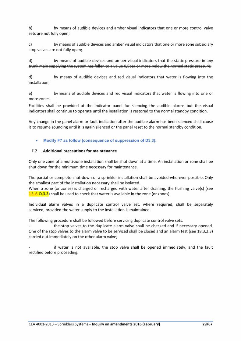
b) by means of audible devices and amber visual indicators that one or more control valve sets are not fully open; c) by means of audible devices and amber visual indicators that one or more zone subsidiary stop valves are not fully open; d) by means of audible devices and amber visual indicators that the static pressure in any trunk main supplying the system has fallen to a value 0,5bar or more below the normal static pressure; d) by means of audible devices and red visual indicators that water is flowing into the installation; e) by means of audible devices and red visual indicators that water is flowing into one or more zones.
Facilities shall be provided at the indicator panel for silencing the audible alarms but the visual indicators shall continue to operate until the installation is restored to the normal standby condition. Any change in the panel alarm or fault indication after the audible alarm has been silenced shall cause it to resume sounding until it is again silenced or the panel reset to the normal standby condition.
Modify F7 as follow (consequence of suppression of D3.3):
F.7 Additional precautions for maintenance
Only one zone of a multi-zone installation shall be shut down at a time. An installation or zone shall be shut down for the minimum time necessary for maintenance. The partial or complete shut-down of a sprinkler installation shall be avoided wherever possible. Only the smallest part of the installation necessary shall be isolated. When a zone (or zones) is charged or recharged with water after draining, the flushing valve(s) (see 13.6 D.3.3) shall be used to check that water is available in the zone (or zones). Individual alarm valves in a duplicate control valve set, where required, shall be separately serviced, provided the water supply to the installation is maintained. The following procedure shall be followed before servicing duplicate control valve sets: - the stop valves to the duplicate alarm valve shall be checked and if necessary opened. One of the stop valves to the alarm valve to be serviced shall be closed and an alarm test (see 18.3.2.3) carried out immediately on the other alarm valve; - if water is not available, the stop valve shall be opened immediately, and the fault rectified before proceeding.

CEA 4001-2013 – Sprinklers Systems – Inquiry on amendments 2016 (February) 30/67
PROPOSAL n° 10 – Modification of Annex K
Modify K7 as follow:
K.7 Special requirements for protection of storage utilising Polypropylene (PP) and
Polyethylene (PE) storage containers
K.7.1 Storage methods ST4 – Palletised rack
Polypropylene and Polyethylene storage containers having a single wall, through which water can
permeate (1) shall be classified as high hazard category III (HHS3).
All other configurations shall be classified as high hazard category IV (HHS4).
“Sprinklers shall have the sensitivity rating “Special” or “Quick” (see note 1 table T 12.5.1a).
NOTE 1: containers shall be assumed to be water permeable if the head of water collected in the
container does not exceed 10 mm for a water discharge into the container, equivalent to 20 mm/min.
(Storage containers with 5 mm diameter drainage holes uniformly distributed at not less than 50
holes/m2 of container plan area, may satisfy the above water permeability requirements).
Consideration shall be given to the influence of the stored goods and any packaging materials on
water permeability.
The maximum horizontal distance of the sprinklers in intermediate levels for category HHS 4 shall not
exceed 1.5 m and 2.5 m for category HHS 3. Sprinkler shall have the sensitivity rating “special” at the
ceiling and “special” or “quick” in intermediate level. The maximum storage height for racks without
intermediate sprinklers shall not exceed 2.1 m for HHS 3 and 1.2 m for HHS 4.
K.7.2 Storage methods ST1 - free or block standing - ST2 and ST3 - post pallet storage
The maximum storage height shall not exceed 3 m.
Only non-combustible pallets with closed surface like steel pallets shall be used. The storage height
on each pallet shall not exceed 1 m. The top storage containers on the pallet shall be closed with a
lid.
Sprinklers shall have the sensitivity rating “Special” or “Quick”.
Film-forming foam shall be added to the water of the sprinkler system.
NOTE: if other sprinkler protection concepts are demonstrated by appropriate fire tests as adequate
protection the above requirements can be adapted.

CEA 4001-2013 – Sprinklers Systems – Inquiry on amendments 2016 (February) 31/67
PROPOSAL n° 11 – Modification of Annex L
Annex L
(normative)
ESFR sprinkler protection
L.10 Introduction
ESFR sprinklers are ceiling sprinklers which have the capability of suppressing fires within storage
risks. There is little room for error in the design and installation of ESFR sprinkler systems; the design
principles and the operating characteristics are significantly different from standard sprinkler
protection. ESFR sprinklers may be unable to cope with adverse design features and non-
compliances, which may be common practice when installing standard sprinkler protection. Design
and installation deviations from this standard may not just result in a reduced effectiveness, but
rather in a total system failure. It is therefore essential that all the requirements of this annex are
complied with, without exception, when applying ESFR protection.
L.11 Scope
This annex specifies requirements and recommendations for the design and installation of ESFR
sprinkler systems in buildings. It covers occupancies, storage arrangements, installation design,
building requirements and the management of protected buildings which is essential to ensure
satisfactory performance of ESFR sprinkler systems.
Only storage configurations and stored goods described in L7 are covered by this annex.
Unless specified differently in this annex L, all the requirements of the CEA 4001 are applicable when
designing and installing ESFR sprinklers.
L.12 Specific definitions
Sprinkler, ESFR (Early Suppression Fast Response) Pattern
A thermosensitive device designed to react at a predetermined temperature by automatically
releasing a stream of water and distributing it in a specified pattern and density over a designated
area to provide early suppression of a fire when installed on the appropriate sprinkler piping with a
suitable water supply.
ESFR sprinklers shall be quick (thermal) response and have one of the following temperature ratings:
Bulbs:
68°C
93°C
Fusible element:
68 to 74°C
93 to 104°C
The higher temperature ratings shall only be used where needed because of high ambient
temperature conditions.
The nominal K factor of ESFR sprinklers shall be between 200 and 360.

CEA 4001-2013 – Sprinklers Systems – Inquiry on amendments 2016 (February) 32/67
In addition to the design criteria specified in tables below, it shall be ensured that the type of ESFR
sprinkler (pendent or upright) used is installed according to its approval conditions (storage height,
max ceiling height, classification of goods…).
Note: higher K factor ESFR are in development. Their use shall be submitted to authority.
Ceiling height
The ceiling height shall be taken as the maximum vertical distance measured from the floor to the
underside of the ceiling. In the case of corrugated metal ceilings with a depth up to 75 mm, the
measurement can be made to the lowest point on the corrugation. In the case of corrugated metal
ceilings with a depth of more than 75 mm, the measurement shall be made to the average level
between the highest and the lowest point of the corrugation.
Maximum storage height
The vertical distance from the floor to the sprinkler deflector minus 1 m or the value shown in tables,
whichever is the lower
Cartoned
A method of storage consisting of cardboard (corrugated), wood or paperboard containers fully
enclosing (no open top) the goods.
exposed
Commodities that contains some plastic (>5%) and that are not in carton packaging (uncatoned) or
covering that absorb water or otherwise appreciably retard the burning hazard of the commodity.
L.13 Classification of goods
For the design of ESFR sprinkler systems the standard classification system within CEA 4001 have
been replaced by four different categories of plastics:
Cartoned unexpanded
Exposed unexpanded
Cartoned expanded
Exposed expanded
For goods containing no plastics at all, or very small amounts of plastics (i.e. Category I and II), the
design criteria for Cartoned unexpanded plastics shall be used.
If the protected commodity contains more than 15 % by weight, or more than 25 % by volume, of a
commodity requiring higher design demands, this higher category shall be used.
Minor numbers of single pallet loads of a higher design category may be allowed within the
protected area without changing the design criteria, providing none of the higher category pallet
loads are placed adjacent to each other However, if more than 15 pallet loads of a higher category
are stored within 9 000 m2, the design shall be based on this higher category.
L.13.4 Laced tyre storage
Tyre storage, often on pallets, where the tyres are stored in layers angled from the horizontal such
that alternating layers dovetail together, in a compact combination, see Figure L.1.4.1a

CEA 4001-2013 – Sprinklers Systems – Inquiry on amendments 2016 (February) 33/67
Figure F 4.1a—Laced tyre storage
L.13.5 Paper categories
The paper is categorized based on its weight per m².
Heavyweight: 100 g/m2
Mediumweight: 50 < 100 g/m2
Lightweight: < 50 g/m2.Tissue paper, toilet paper, towelling and other similar absorbent paper
products, shall be protected as lightweight paper, regardless of weight.
L.14 General
ESFR sprinkler protection shall only be used in buildings where the property, storage systems and
contents are controlled by appropriate management systems. The management system
documentation shall include procedures for at least the following:
a) risk assessment controls for incoming goods;
b) routine checking and inspection procedures;
c) sprinkler system maintenance contract with a qualified company
d) maintenance of an outline specification for the building and fire protection with a record of any
changes which may influence the performance of the sprinkler system;
e) regular review of methods of storage;
f) regular review of hazard;
g) regular review of compliance with ESFR installation requirements;
h) dealing with non-compliances.
NOTE The critical review of the hazard and storage methods specified in (a), (b), (d), (e), (f) and (g)
above should, at least, be in accordance chapter 18.
Regular review of hazard should include checking that aisles and flues in storages comply with
respective requirements.
The written procedures should encompass actions to be taken if major non-compliances occur and
should include informing authorities such as fire authorities and leading insurers.
L.15 Occupancies and fire hazards
ESFR sprinklers may be used to protect storages in accordance with Tables T.L.7.4b to T.L.7.4p. Table
T.L.7.4a provides a reference guide to Tables T.L.7.4b to T.L.7.4p.
ESFR sprinklers shall not be used to protect areas where one of the following is present:

CEA 4001-2013 – Sprinklers Systems – Inquiry on amendments 2016 (February) 34/67
a) Commodities and storage configurations which have not been approved by the authorities for
protection with ESFR sprinklers, e.g. flammable and combustible liquids;
b) Open top containers which may retain water;
c) Automatic heat and smoke venting;
Note 1: ESFR sprinkler protection may be used in conjunction with manually operated smoke
ventilation systems, suitable only for heat and smoke ventilation purposes, operated by the fire
brigade.
Note 2: If accepted by the authority, smoke vents can be automatically activated by individual
thermal sensitive element, providing they are rated no less than 140°C.
d) Solid shelving larger than 2 m2 per shelf.
L.16 ST4 (Racked), ST5 (shelved), ST2 and ST3 (post pallet) storage
L.16.4 Longitudinal and transverse flues
Storages shall have longitudinal and transverse flues, which are:
a) continuous for the full height of each block of storage;
b) vertically aligned;
c) free of stored goods and of any kind of obstruction
d) regularly spaced and having dimensions as follows:
Maintain all transverse flue spaces at a minimum net width of 0,075m throughout the
vertical height of the rack ; and
Maintain longitudinal flue spaces at a minimum net width of 0,15m throughout the vertical
height of the rack.
e) longitudinal flues shall be spaced at distances of not more than 3.0 m
f) Transverse flues shall be spaced at distances of not more than 3.0 m
g) The area between flue spaces shall not exceed 2m².
Note : e.g. a pallet of 2,5m in length cannot exceed 0,8m in width and shall be surrounded by flue
spaces as defined in d).
L.16.5 Shelving
Single and double row shelved racks have to be considered as solid shelves which cannot be
protected with ESFR sprinklers, except if they comply with one of the following:
a) slatted shelves shall have shelf open areas, uniformly interspaced, of at least 50 % of the shelf
plan area. The distance between openings shall not exceed 0,15 m; or
b) grated or mesh type shelves shall have uniform openings of at least 50 % of the shelf plan area.
The horizontal distance between openings shall not exceed 0,15 m; or

CEA 4001-2013 – Sprinklers Systems – Inquiry on amendments 2016 (February) 35/67
c) shelves having openings of less than 50% of the plan area shall not exceed 2.0 m² total plan area
and shall be bounded on all four edges by flue spaces of not less than 0.15 m width;
In all the above mentioned cases, the load shall not obstruct the transverse flue space. The distance
between 2 adjacent transverse flue spaces shall not exceed 3m.
When conditions above are met, the rack can be considered as open rack and may be protected by
an ESFR system.
When ST5 is mentioned in annex L, it shall be limited to 3,2m storage height and to a maximum
length of 12m with no less than 3,2m separation to adjacent storage, unless the requirements of L7.2
is fulfilled.
L.16.6 In-rack sprinklers for ESFR systems
In some cases additional In-Rack Sprinklers are required. This means that ceiling only protection is
not able to cool and/or control fire spread. In these cases one line of In- Rack Sprinklers shall be
provided close to 1/2 the storage height of the rack. The In-Rack Sprinklers shall be positioned at
each intersection of the transversal and longitudinal flue. Sprinklers need to be positioned within
150 mm of the centerline of the flue. All flues need to be protected.
Where required, one level of K115 or K160 quick response sprinklers shall be used.
In-rack sprinkler hydraulic design criteria shall be the most hydraulically remote eight sprinklers at
227l/min each.
Ceiling sprinkler demand shall be included in the hydraulic calcultion for the in-rack sprinkler
protection.
The most unfavourable demand shall be the most unfavourable combination between ceiling
demand and in-rack demand, that is not necessarily the most unfavourable ceiling demand neither
the most unfavourable in-rack demand.
L.16.7 Design requirements
Minimum operating pressure for the ESFR sprinklers included in the design area, see L.10.6.4, shall
be taken from the appropriate tables T.L.7.4b to T.L.7.4p. For guidance on the appropriate table, see
Table T.L.7.4a
Table T 7.4a — Guide to ESFR sprinkler use
Storage method
ST1 ST2/ST3 ST4 ST5
Commodity Table reference
Plastics
Unexpanded cartoned T. L.7.4b T .L.7.4c T .L.7.4c T .L.7.4b Unexpanded exposed T .L.7.4d T .L.7.4e T .L.7.4e T .L.7.4d Expanded cartoned T .L.7.4F T .L.7.4g T .L.7.4g T .L.7.4F Expanded exposed T .L.7.4h T .L.7.4i T .L.7.4i T .L.7.4h
Rubber tyres T. L.7.4n T .L.7.4n

CEA 4001-2013 – Sprinklers Systems – Inquiry on amendments 2016 (February) 36/67
Paper rolls stored on end: Light weight T .L.7.4j - - - Medium weight T .L.7.4k Heavy weight T .L.7.4l - - - Heavy weight plastic coated T .L.7.4m - - -
Commodities stored below Mezzanines T .L.7.4o T .L.7.4p T .L.7.4p -
Table T 7.4b —Unexpanded plastic in cartons, ST1 or ST5 storage
Storage applications: ST1 Free standing or block storage ST5 Solid or slatted shelves 1m or less wide (see L7.2)
Commodities: Cartoned unexpanded Plastics
Maximum storage height
Maximum ceiling height M
9,1 10,7 12,2 13,7 M
Sprinkler minimum operating pressure Bar
ESFR pendent or upright sprinkler nominal k-factor 200
7,6 3,5 5,2 NA NA
9,1 NA 5,2 NA NA
ESFR pendent sprinkler nominal k-factor 240
7,6 2,4 3,6 3,6 NA
9,1 NA 3,6 3,6 NA
10,7 NA NA 3,6 NA
ESFR upright sprinkler nominal k-factor 240
7,6 2,4 3,6 NA NA
9,1 NA 3,6 NA NA
ESFR pendent sprinkler nominal k-factor 320
7,6 1,7 2,4 2,8 2,8
9,1 NA 2,4 2,8 2,8
10,7 NA NA 2,8 2,8
12,2 NA NA NA 2,8
ESFR pendent sprinkler nominal k-factor 360
7,6 1,0 1,4 1,7 2,8
9,1 NA 1,4 1,7 2,8
10,7 NA NA 1,7 2,8
12,2 NA NA NA 2,8
NA Not applicable

CEA 4001-2013 – Sprinklers Systems – Inquiry on amendments 2016 (February) 37/67
Table T 7.4c — Unexpanded plastic in cartons, ST2, ST3 or ST4 storage
Storage applications: ST2/ST3 Post pallets ST4 Palletized racking
Commodities: Plastics: cartoned unexpanded
Maximum storage height
Maximum ceiling height M
9,1 10,7 12,2 13,7 m
Sprinkler minimum operating pressure Bar
ESFR pendent sprinkler nominal k-factor 200
7,6 3,5 5,2 6,2 + 1 level of in-rack
6,2 + 1 level of in-rack
9,1 NA 5,2 6,2 + 1 level of in-rack
6,2 + 1 level of in-rack
10,7 NA NA 6,2 + 1 level of in-rack
6,2 + 1 level of in-rack
12,2 NA NA NA 6,2 + 1 level of in-rack
ESFR upright sprinkler nominal k-factor 200
7,6 3,5 5,2 NA NA
9,1 NA 5,2 NA NA
ESFR pendent sprinkler nominal k-factor 240
7,6 2,4 3,6 3,6 4,3+ 1 level of in-rack
9,1 NA 3,6 3,6 4,3 + 1 level of in-rack
10,7 NA NA 3,6 4,3 + 1 level of in-rack
12,2 NA NA NA 4,3 + 1 level of in-rack
ESFR upright sprinkler nominal k-factor 240
7,6 2,4 3,6 NA NA
9,1 NA 3,6 NA NA
ESFR pendent sprinkler nominal k-factor 320
7,6 1,7 2,4 2,8 2,8
9,1 NA 2,4 2,8 2,8
10,7 NA NA 2,8 2,8
12,2 NA NA NA 2,8
ESFR pendent sprinkler nominal k-factor 360
7,6 1,0 1,4 1,7 2,8
9,1 NA 1,4 1,7 2,8
10,7 NA NA 1,7 2,8
12,2 NA NA NA 2,8
NA - Not applicable

CEA 4001-2013 – Sprinklers Systems – Inquiry on amendments 2016 (February) 38/67
Table T 7.4d — Exposed unexpanded plastic, ST1 or ST5 storage
Storage applications: ST1 Free standing or block storage ST5 Solid or slatted shelves 1m or less wide (see L7.2)
Commodities: Plastics :exposed unexpanded
Maximum storage height
Maximum ceiling height M
9,1 10,7 12,2 13,7 m
Sprinkler minimum operating pressure Bar
ESFR pendent sprinkler nominal k-factor 200
7,6 3,5 5,2 NA NA
9,1 NA 5,2 NA NA
ESFR pendent sprinkler nominal k-factor 240
7,6 2,4 3,6 3,6 NA
9,1 NA 3,6 3,6 NA
10,7 NA NA 3,6 NA
ESFR pendent sprinkler nominal k-factor 320
7,6 2,4 3,5 3,5 NA
9,1 NA 3,5 3,5 NA
10,7 NA NA 3,5 NA
ESFR pendent sprinkler nominal k-factor 360
7,6 2,4 3,5 3,5 NA
9,1 NA 3,5 3,5 NA
10,7 NA NA 3,5 NA
NA - Not applicable

CEA 4001-2013 – Sprinklers Systems – Inquiry on amendments 2016 (February) 39/67
Table T 7.4e — Exposed unexpanded plastic, ST2, ST3 or ST4 storage
Storage applications: ST2/ST3 Post pallets ST4 Palletized racking
Commodities: Plastics :exposed unexpanded
Maximum storage height
Maximum ceiling height M
9,1 10,7 12,2 13,7 m
Sprinkler minimum operating pressure Bar
ESFR pendent sprinkler nominal k-factor 200
7,6 3,5 5,2 5,2 6,2 + 1 level of in-rack
9,1 NA 5,2 5,2 6,2 + 1 level of in-rack
10,7 NA NA 5,2 6,2 + 1 level of in-rack
12,2 NA NA NA 6,2 + 1 level of in-rack
ESFR pendent sprinkler nominal k-factor 240
7,6 2,4 3,6 4,1 4,3 + 1 level of in-rack
9,1 NA 3,6 4,1 4,3 + 1 level of in-rack
10,7 NA NA 4,1 4,3 + 1 level of in-rack
12,2 NA NA NA 4,3 + 1 level of in-rack
ESFR pendent sprinkler nominal k-factor 320
7,6 2,4 3,5 4,1 4,3+ 1 level of in-rack
9,1 NA 3,5 4,1 4,3+ 1 level of in-rack
10,7 NA NA 4,1 4,3+ 1 level of in-rack
12,2 NA NA NA 4,3+ 1 level of in-rack
ESFR pendent sprinkler nominal k-factor 360
7,6 2,4 3,5 4,1 4,3+ 1 level of in-rack
9,1 NA 3,5 4,1 4,3+ 1 level of in-rack
10,7 NA NA 4,1 4,3+ 1 level of in-rack
12,2 NA NA NA 4,3 + 1 level of in-rack
NA - Not applicable

CEA 4001-2013 – Sprinklers Systems – Inquiry on amendments 2016 (February) 40/67
Table T 7.4f — Expanded plastic in cartons, ST1 or ST5 storage
Storage applications: ST1 Free standing or block storage ST5 Solid or slatted shelves 1m or less wide (see L7.2)
Commodities: Plastics: cartoned expanded
Maximum storage height
Maximum ceiling height
M
9,1 10,7 12,2 13,7 m
Sprinkler minimum operating pressure
Bar
ESFR pendent or upright sprinkler nominal k-factor 200
7,6 3,5 NA NA NA
ESFR pendent or upright sprinkler nominal k-factor 240
7,6 2,4 NA NA NA
ESFR pendent sprinkler nominal k-factor 320
7,6 2,4 NA NA NA
ESFR pendent sprinkler nominal k-factor 360
7,6 2,4 NA NA NA
NA - Not applicable

CEA 4001-2013 – Sprinklers Systems – Inquiry on amendments 2016 (February) 41/67
Table T 1.4g — Expanded plastic in cartons, ST2, ST3 or ST4 storage
Storage applications: ST2/ST3 Post pallets ST4 Palletized racking
Commodities: Plastics: cartoned expanded
Maximum storage height
Maximum ceiling height
M
9,1 10,7 12,2 13,7 m
Sprinkler minimum operating pressure
Bar
ESFR pendent or upright sprinkler nominal k-factor 200
7,6 3,5 NA NA NA
ESFR pendent or upright sprinkler nominal k-factor 240
7,6 2,4 NA NA NA
ESFR pendent sprinkler nominal k-factor 320
7,6 2,4 NA NA NA
ESFR pendent sprinkler nominal k-factor 360
7,6 2,4 NA NA NA
NA - Not applicable

CEA 4001-2013 – Sprinklers Systems – Inquiry on amendments 2016 (February) 42/67
Table T 7.4h — Exposed expanded plastic, ST1 or ST5 storage
Storage applications:
ST1 Free standing or block storage ST5 Solid or slatted shelves 1m or less wide (see L7.2)
Commodities: Plastics: exposed expanded
Maximum storage height
Maximum ceiling height
M
7,6 9,1 10,7 12,2 m
Sprinkler minimum operating pressure
Bar
ESFR pendent sprinkler nominal k-factor 200
6,1 3,5 6,9 NA NA
7,6 NA 6,9 NA NA
ESFR upright sprinkler nominal k-factor 200
6,1 3,5 NA NA NA
ESFR pendent sprinkler nominal k-factor 240
6,1 2,4 6,9 NA NA
7,6 NA 6,9 NA NA
ESFR upright sprinkler nominal k-factor 240
6,1 2,4 NA NA NA
ESFR pendent sprinkler nominal k-factor 320
6,1 1,7 4,8 NA NA
7,6 NA 4,8 NA NA
ESFR pendent sprinkler nominal k-factor 360
6,1 1,4 4,8 NA NA
7,6 NA 4,8 NA NA
NA - Not applicable

CEA 4001-2013 – Sprinklers Systems – Inquiry on amendments 2016 (February) 43/67
Table T 7.4i — Exposed expanded plastic, ST2, ST3 or ST4 storage
Storage applications: ST2/ST3 Post pallets ST4 Palletized racking
Commodities: Plastics: exposed expanded
Maximum storage height
Maximum ceiling height
M
7,6 9,1 10,7 12,2 m
Sprinkler minimum operating pressure
Bar
ESFR pendent sprinkler nominal k-factor 200
6,1 5,2 6,9 NA NA
7,6 NA 6,9 NA NA
ESFR pendent sprinkler nominal k-factor 240
6,1 3,6 4,8 NA NA
7,6 NA 4,8 NA NA
ESFR pendent sprinkler nominal k-factor 320
6,1 3,6 4,8 NA NA
7,6 NA 4,8 NA NA
ESFR pendent sprinkler nominal k-factor 360
6,1 3,6 4,8 NA NA
7,6 NA 4,8 NA NA
NA - Not applicable
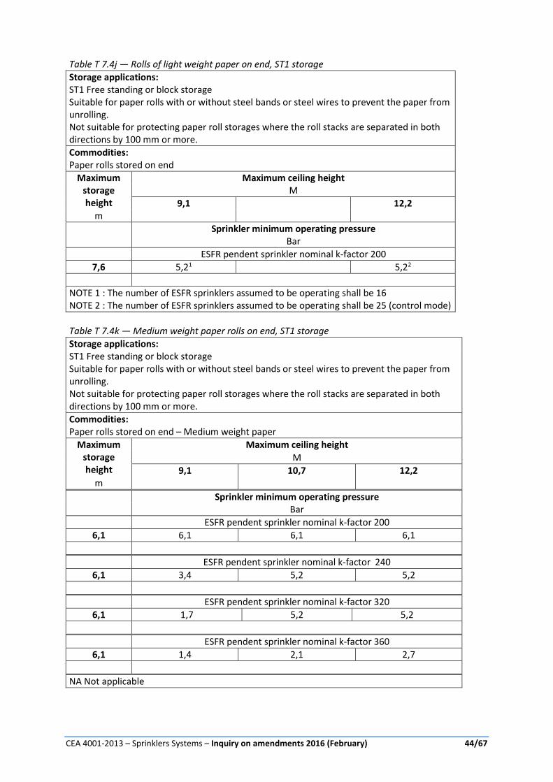
CEA 4001-2013 – Sprinklers Systems – Inquiry on amendments 2016 (February) 44/67
Table T 7.4j — Rolls of light weight paper on end, ST1 storage
Storage applications: ST1 Free standing or block storage Suitable for paper rolls with or without steel bands or steel wires to prevent the paper from unrolling. Not suitable for protecting paper roll storages where the roll stacks are separated in both directions by 100 mm or more.
Commodities: Paper rolls stored on end
Maximum storage height
Maximum ceiling height
M
9,1 12,2 m
Sprinkler minimum operating pressure
Bar
ESFR pendent sprinkler nominal k-factor 200
7,6 5,21 5,22
NOTE 1 : The number of ESFR sprinklers assumed to be operating shall be 16 NOTE 2 : The number of ESFR sprinklers assumed to be operating shall be 25 (control mode)
Table T 7.4k — Medium weight paper rolls on end, ST1 storage
Storage applications: ST1 Free standing or block storage Suitable for paper rolls with or without steel bands or steel wires to prevent the paper from unrolling. Not suitable for protecting paper roll storages where the roll stacks are separated in both directions by 100 mm or more.
Commodities: Paper rolls stored on end – Medium weight paper
Maximum storage height
Maximum ceiling height
M
9,1 10,7 12,2 m
Sprinkler minimum operating pressure
Bar
ESFR pendent sprinkler nominal k-factor 200
6,1 6,1 6,1 6,1
ESFR pendent sprinkler nominal k-factor 240
6,1 3,4 5,2 5,2
ESFR pendent sprinkler nominal k-factor 320
6,1 1,7 5,2 5,2
ESFR pendent sprinkler nominal k-factor 360
6,1 1,4 2,1 2,7
NA Not applicable

CEA 4001-2013 – Sprinklers Systems – Inquiry on amendments 2016 (February) 45/67
Table T 7.4l — Heavy weight paper rolls stored on end, ST1 storage
Storage applications: ST1 Free standing or block storage Where the paper roll stacks are separated in both directions by 100 mm or more the paper rolls shall have steel bands or steel wires to prevent the paper from unrolling, otherwise protection suitable for paper rolls with or without steel bands or steel wires.
Commodities: Paper rolls stored on end – heavy weight paper
Maximum storage height
Maximum ceiling height
m
9,1 10,7 12,2 13,7 m
Sprinkler minimum operating pressure Bar
ESFR pendent sprinkler nominal k-factor 200
7,6 3,4 5,2 5,2 NA
9,1 NA 5,2 5,2 NA
ESFR pendent sprinkler nominal k-factor 240
7,6 2,4 3,6 3,6 NA
9,1 NA 3,6 3,6 NA
ESFR pendent sprinkler nominal k-factor 320
7,6 1,7 2,8 2,8 3,4
9,1 NA 2,8 2,8 3,4
ESFR pendent sprinkler nominal k-factor 360
7,6 1 1,7 1,7 3,4
9,1 NA 1,7 1,7 3,4
NA - Not applicable

CEA 4001-2013 – Sprinklers Systems – Inquiry on amendments 2016 (February) 46/67
Table T 7.4m — Plastic coated heavy weight paper, ST1 storage
Storage applications: ST1 Free standing or block storage Where the paper roll stacks are separated in both directions by 100 mm or more the paper rolls shall have steel bands or steel wires to prevent the paper from unrolling, otherwise protection suitable for paper rolls with or without steel bands or steel wires.
Commodities: Paper rolls stored on end – plastic coated heavy weight paper
Maximum storage height
Maximum ceiling height
M
9,1 10,7 12,2 m
Sprinkler minimum operating pressure
Bar
ESFR pendent sprinkler nominal k-factor 200
7,6 3,4 5,2 5,2
ESFR pendent sprinkler nominal k-factor 240
7,6 2,4 3,6 3,6

CEA 4001-2013 – Sprinklers Systems – Inquiry on amendments 2016 (February) 47/67
Table T 7.4n — Rubber tyres, ST3 or ST4 storage
Storage applications: ST3 open portable racks in multiple rows ST4 Palletized racking
Open bottomed storage systems only.
Commodities: Rubber tyres
Maximum storage height
Maximum ceiling height
m
9,1 10,7 12,2 m
Sprinkler minimum operating pressure
Bar
ESFR pendent sprinkler nominal k-factor 200
7,6 3,51 5,2² NA
ESFR pendent sprinkler nominal k-factor 240
7,6 2,41 3,6² 3,6²
ESFR pendent sprinkler nominal k-factor 320
7,6 1,71 2,4² 3,6²
ESFR pendent sprinkler nominal k-factor 360
7,6 1,01 1,7² or 2,8 2,8
9,1 NA 5,2 5,2
Note 1: Tyres shall be stored on side or on tread, but not laced Note 2: Tyres shall be stored only on side.

CEA 4001-2013 – Sprinklers Systems – Inquiry on amendments 2016 (February) 48/67
Table T L.7.4o — Various commodities beneath mezzanines up to 4.5m, ST1 storage
Storage applications: Mezzanines with: ST1 Free standing or block stacking,
Commodities: Plastics: cartoned unexpanded Plastics :exposed unexpanded Plastics: cartoned expanded Plastics: exposed expanded Paper rolls stored on end – Medium weight paper
Suitable for paper rolls with or without steel bands or steel wires to prevent the paper from unrolling. Not suitable for protecting paper roll storages where the roll stacks are separated in both directions by 100 mm or more.
Maximum storage height Maximum mezzanine height
m
4,5 M
Sprinkler minimum operating pressure
Bar
ESFR pendent or upright sprinkler nominal k-factor 200
Mezzanine height -1m clearance 3,5
ESFR pendent or upright sprinkler nominal k-factor 240
Mezzanine height -1m clearance 2,4
Table T 7.4p — Various commodities beneath mezzanines up to 4.5m , ST3 and ST4 storage
Storage applications: Mezzanines with: ST3 Post pallets in multiple rows ST4 Palletized racking
Commodities: Plastics: cartoned unexpanded Plastics :exposed unexpanded Plastics: cartoned expanded Plastics: exposed expanded
Maximum storage height Maximum ceiling height
m
≤ 4,5 m
Sprinkler minimum operating pressure
Bar
ESFR pendent sprinkler nominal k-factor 200
Mezzanine height -1m clearance 3,5
ESFR pendent sprinkler nominal k-factor 240
Mezzanine height -1m clearance 2,4

CEA 4001-2013 – Sprinklers Systems – Inquiry on amendments 2016 (February) 49/67
L.17 Building requirements
L.17.4 Roof or ceiling slope
The roof or ceiling slope shall not exceed 17% (170 mm/m).
L.17.5 Measures required to correct excessive roof or ceiling slope.
Where roof or ceiling slopes exceed 17%, the roof or ceiling shall be under-drawn with a suspended
ceiling. The suspended ceiling shall be of non-combustible construction, having an acceptable slope.
ESFR sprinklers shall be deployed below the suspended ceiling. Standard sprinkler protection shall be
installed within this concealed space if required by 5.4.
NOTE Ceiling slope influences the movement of hot gases across the ceiling and therefore influences
the operation of sprinkler heads during a fire. Excessive ceiling slope may result in the operation
sprinklers remote from the fire whilst delaying the operation of sprinklers in close proximity to the
fire.
L.17.6 Ceiling strength
Ceilings and any sub-ceilings shall be firmly secure and shall be capable of withstanding a vertical
upward thrust of 50 N/m2.
NOTE Ceiling materials considered suitable are 10 mm gypsum board, corrugated and sheet steel
and mineral tiles.
L.17.7 Sky lights
Sky lights shall be flush to the ceiling or underdrawn at the ceiling level. Sky lights shall be capable of
withstanding a temperature of 300°C for a period of at least 5 min.
Additional sprinklers need to be installed in skylights with a volume greater than 1 m3, measured
above the normal ceiling level, when the distance from the normal or suspended ceiling level to the
top of the deflector exceeds the maximum allowable distance between the ESFR sprinkler and
ceiling, see Table T L.8.9a. Any additional sprinkler shall also be of the ESFR type.
L.17.8 Powered ventilation
Coordinate the location of sprinklers and the design of powered heating, ventilation and air
conditioning for buildings protected by suppression mode sprinklers so that the air velocity at
sprinklers does not exceed 1.5 m/sec.
If it is not possible to meet this requirement, at least one of the following measures shall in this case
be adopted to mitigate the effects of air movement on ESFR sprinklers in the event of fire:
a) where powered ventilation is employed, the buildings shall be protected by a fire alarm
installation approved by the authorities. The powered ventilation shall be stopped and any
dampers closed automatically in response to the fire detection system alarm of fire; or
b) the horizontal distance between stored goods and the perimeter of the extraction ventilator
openings shall be not less than L (in m) given by the equation:
L = 1/2S + d
where

CEA 4001-2013 – Sprinklers Systems – Inquiry on amendments 2016 (February) 50/67
S is the sprinkler spacing (in m);
d is the ventilator duct diameter (in m).
or
c) install a horizontal sub-ceiling below the extraction ventilator openings. ESFR sprinklers shall be
located below the sub-ceiling in accordance with the normal spacing requirements, (see Figure F
L.2). The sub-ceiling shall have a minimum diameter or cross-sectional dimension W given by
either of the equations below.
If the ventilation airflow rate is known:
W = Q / 283 h
If the ventilation airflow rate is unknown:
W = 2,6 A* / h
where
Q is the ventilator air flow rate (in m3/min);
A* is the ventilator opening area (in m2)
h is the vertical distance between ceiling and top of the subceiling (in m).
Ceiling sprinklers shall be a horizontal distance of at least 0,7 times the sprinkler spacing from the
perimeter of the sub-ceiling.
NOTES
Note 1 Powered ventilators and fire dampers should preferably be stopped before the first sprinkler
operates. Fire detection systems should be either:
aspirating smoke detectors installed in all ventilation ducts extracting from the ESFR
protected risk; or
a fire detection system of detection performance equivalent to an aspirating smoke
detection system.
Note 2 If the air flow rate through the ventilator is not known then the duct velocity should be
measured using a suitable device such as Pitot tube and micromanometer. The air flow rate Q (in
m3/min) through a circular section duct may be calculated using the equation:
Q = 49 / 60 x A x V
where
A is the cross-sectional area of a circular duct (in m2)
v is the maximum velocity through the duct (in m/min)

CEA 4001-2013 – Sprinklers Systems – Inquiry on amendments 2016 (February) 51/67
Figure 1 — Sprinklered sub-ceiling below a ventilator
Powered ventilation
Key 1. Sub-ceiling dimension – W (in m)
2. Sub-ceiling sprinkler
3. Roof or ceiling sprinkler
4. Sub-ceiling
5. Ventilator
6. Ventilator diameter – D (in m)
7. Ceiling
8. Vertical distance between sub-ceiling and ventilator – h (in m)
Ventilator air flow rate – Q(in m3/min)
L.17.9 Walkways and conveyors
Walkways and conveyors, not exceeding 3,0 m width, shall be protected underneath by a centrally
located single row of ESFR sprinklers or spray pattern sprinklers. The sprinklers shall be spaced not
more than 3,0 m apart. Walkways and conveyors exceeding 3,0 m width shall be treated as
mezzanines.
L.17.10 Sprinkler protection beneath mezzanines
Where the height of the mezzanines above the floor exceeds 4,5 m, the underside of the mezzanines
shall be protected by ESFR sprinklers according to table T L7.4b to T L7.4n. Where the height of the
mezzanines above the floor is 4,5 m or less ESFR according to table T L7.4o or T L7.4p, or appropriate
spray pattern sprinkler protection may be employed.
Where mezzanines have openings into the protected building, the storage beneath the mezzanine
shall not be closer to the open face than:
a) the outside line of sprinklers beneath the mezzanine, if there is no vertical smoke curtain of at
least 600 mm depth; or
b) within the bounds of a 600 mm deep smoke curtain.
NOTE Where spray pattern sprinkler protection is used below low mezzanines, it should fully comply
with the appropriate CEA 4001 clauses.

CEA 4001-2013 – Sprinklers Systems – Inquiry on amendments 2016 (February) 52/67
L.18 ESFR sprinkler installation design.
L.18.1 Installation type
Sprinkler installations shall be of the wet-pipe type.
L.18.2 ESFR sprinkler location relative to obstructions at or near the ceiling or roof
Pendent ESFR sprinklers shall be located at the appropriate horizontal distance from obstructions at
the ceiling or roof such as beams, ducts, joists, distribution pipes, range pipes or light fittings as given
in Table T L.8.9a
NOTE ESFR sprinklers should be located no closer than 0,1 m horizontally from the bottom near
side edge of joists, trusses or similar obstructions. In some instances it may be advantageous to vary
ESFR sprinkler spacings across the ceiling to avoid obstructions to the sprinkler water distribution.
Table T L18.2a — ESFR sprinkler location relative to ceiling obstructions such as beams or joists
Distance a 1 Distance b 1
Horizontal distance from sprinkler axis to side of obstruction Maximum height of ESFR sprinkler deflector above (+) bottom of obstruction
Greater than mm Less than mm mm
100 300 0
300 500 40
500 600 75
600 800 140
800 900 200
900 1100 250
1100 1200 300
1200 1400 380
1400 1500 460
1500 1700 560
1700 1800 660
1800 1850 790
Note 1: See Figure F L18.2b
Figure F L18.2b Position of deflector when located above bottom of beam or other obstruction
located at the ceiling.

CEA 4001-2013 – Sprinklers Systems – Inquiry on amendments 2016 (February) 53/67
Key:
a - Object is located entirely within checkerboard area: this does not represent any obstruction to the
sprinkler.
b - Object is located entirely within discharge area of the sprinkler: this does not represent an
obstruction to the umbrella discharge pattern of the sprinkler. However, it should be verified if the
object represents an obstruction to the sprinkler’s inner core discharge.
c - Umbrella discharge pattern obstructions are all objects (usually situated at or near ceiling level)
which cross the border from the checkerboard area into the inner core area of the sprinkler thus
disrupting the umbrella pattern.
If the above recommended distances cannot be ensured, install two rows of sprinklers on both side
of the object. The maximum distance between the object and the sprinkler shall not exceed half (1/2)
of the maximum recommended distance between sprinklers for the specific ceiling height.
Figure FL18.2d — Position of deflector when located above bottom of beam or other obstruction
located at the ceiling and the recommended distances can not be ensured.
Note: Exceptions
i.) The object located at or near ceiling level is at least 70% open
ii.) The object located at or near ceiling level is no wider than 75 mm and is separated from
other objects by a minimum of 300 mm.
Upright ESFR sprinklers shall be located at the appropriate horizontal distance from obstructions at
the ceiling or roof such as beams, ducts, joists, distribution pipes, range pipes or light fittings. See
individual listings for each sprinkler type.
ESFR sprinklers shall be permitted for use in buildings with all types of ceiling construction. Where
the depth of solid structural members (beams, stem etc) exceed 300 mm, ESFR sprinklers shall be
installed in each bay formed by the solid structural members. Minimum sprinkler spacing and area of
coverage shall comply with the requirements of Table T L.18.2a

CEA 4001-2013 – Sprinklers Systems – Inquiry on amendments 2016 (February) 54/67
L.18.10 ESFR Obstructions entirely below Sprinkler Deflector
Figure F L.18.10a. Position of objects when located entirely below ESFR sprinklers
Key:
a - The maximum width of the object permitted in this area is 20 mm
b - The maximum width of the object permitted in this area is 32 mm
c - The maximum width of the object permitted in this area is 50 mm
d - Objects having a width between 50 and 300 mm (inclusive) shall be located at least 300 mm
horizontally from the sprinkler deflector. A minimum of 450 mm vertical distance shall be kept
between the underside of the object and the top of storage.
e - Objects having a with between 300 and 600 mm (not inclusive) should be located at least 600 mm
horizontally from the sprinkler deflector. A minimum of 900 mm vertical distance shall be kept
between the underside of the object and the top of storage.
f - Objects having a width between 600 and 1200 mm (inclusive) shall be fitted with one row of
sprinklers centered under them, having the same branch line size, same orientation, same
temperature rating and same K-Factor like the ceiling level sprinklers.
g - Objects having a width between 1200 and 3000 mm (inclusive) shall be fitted with two rows of
sprinklers under them, having the same branch line size, same orientation, same temperature rating
and same K-Factor like the ceiling level sprinklers.
*Note : Upright Storage sprinklers can tolerate individual objects up to 100 mm wide located directly
below them at any vertical distance.
All the above mentioned recommendations should be verified together with each other. The position
of the objects shall be verified for the whole space between the sprinkler deflector and the top of
storage.

CEA 4001-2013 – Sprinklers Systems – Inquiry on amendments 2016 (February) 55/67
L.18.11 Open Structures like Bar Joists or Open Trusses.
ESFR sprinklers shall be installed a minimum of 0,3 m horizontally from the bottom of a bar joist or
open truss.
L.19 Pipe sizing
ESFR sprinkler installations shall be fully hydraulically calculated.
L.19.1 Minimum pipe sizes
The nominal bore of distribution pipes and range pipes shall not be less than 25 mm.
L.19.2 Minimum ESFR sprinkler flow pressure
The calculated discharge pressure of any ESFR sprinkler, when all the design sprinklers at ceiling level
plus any additional sprinklers under obstructions are operating, shall not be less than as given in
Tables T L.7.4b to T L.7.4p
L.19.3 The number of sprinklers assumed to be operating
The number of roof or ceiling ESFR sprinklers assumed to be operating shall be twelve (12).
In case of ESFR sprinklers below solid mezzanines with a height of 4,5 m or less, the number of these
ESFR sprinklers assumed to be operating shall be six (6), without the need to add them to the
demand of the roof sprinkler.
In case of open mezzanines, the authorities shall be consulted.
Any additional ESFR sprinklers below obstructions do not need to be added to the ceiling demand in
the hydraulic calculation.
Where additional spray sprinklers are installed below obstructions near the floor level , e.g. to
protect the area below conveyors, sprinklers with a k-factor of minimum 115 shall be provided and
up to 8 sprinklers shall be added to demand of the ceiling in the hydraulic calculation at a rate of 115
l/min per spray sprinkler
Where the tables above specify “1 level of in-racks”, spray sprinklers with a k-factor of minimum 115
shall be provided and 8 in-rack sprinklers shall be added to demand of the ceiling in the hydraulic
calculation at a rate of 230 l/min per spray sprinkler.
L.19.4 Shape of design sprinkler area
To determine the water supply capacity and for pipe sizing purposes , the shape of the design
sprinkler area shall be taken as four adjacent sprinklers operating on each of three adjacent range
pipes, plus any additional sprinklers as specified. Where ESFR sprinklers are used to protect storage
areas beneath mezzanines and where the design number of sprinklers is reduced to six ESFR
sprinklers, then three sprinklers shall be assumed to operate on each of two ranges.
NOTE Where range pipes have fewer than the designated number of ESFR sprinklers per range, all
the sprinklers should be assumed to be operating, and the number of ranges involved should be
increased to compensate.

CEA 4001-2013 – Sprinklers Systems – Inquiry on amendments 2016 (February) 56/67
L.19.5 Sprinklers beneath obstructions etc
For pipe sizing purpose, any additional ESFR sprinklers beneath obstructions within the design area,
shall be assumed to be operating, at not less than the specified ESFR sprinkler flow pressure as
defined in Tables T L.7.4b to T L.7.4p
NOTE See also L.11 for additional In-Rack sprinkler requirements.
L.20 Sprinkler spacing and location
L.20.1 ESFR sprinkler area of coverage
The area of coverage and spacing of ESFR sprinklers shall comply with Table T L.20.
Table 10.1a — ESFR sprinkler spacing
Ceiling height Distance between sprinklers Area of coverage per sprinkler
Minimum Maximum Minimum Maximum
m m m m2 m2
≤ 9,1 2,4 3,7 6,0 9,3
> 9,1 ≤ 13,7 2,4 3,1 6,0 9,3
L.20.2 Obstructions
Elimination of obstructions is critical to the success of suppression mode sprinklers. There can be
cases where a slight extension in sprinkler spacing and coverage in isolated areas can eliminate
obstructions. If increasing spacing between two adjacent heads on ranges or between two adjacent
ranges can eliminate obstructions, then the max spacing may be extended as follows, limited to a
maximum of two adjacent sprinklers on ranges or two adjacent ranges.
a) In buildings up to 9,1 m high, the maximum spacing of 3,7 m and area of coverage may be
increased to 10.7 m2 for those sprinklers that need to be moved in order to be at least 300 mm
from joists.
b) In buildings over 9,1 and up to 12.2 m high, the maximum spacing of 3,1 m may be increased to
3.4 m, with a maximum area of coverage of 10,2 m2, for those sprinklers that need to be moved
in order to be at least 300 mm from bar joists.
L 10.3 Sprinkler positioning relative to roof and ceilings
Sprinklers shall be located beneath the ceiling in accordance with Table T L.21
Table T L2 — Sprinkler distance from the underside of the ceiling
Sprinkler nominal K factor l.min-1.bar-1/2
Vertical distance from the underside of the ceiling to the sprinkler deflector
Not less than mm
Not more than mm
200, 240 and 280 –pendent ESFR
150 360
200 and 240 –upright ESFR
75 150
320 and 360 ESFR 150 460

CEA 4001-2013 – Sprinklers Systems – Inquiry on amendments 2016 (February) 57/67
L.10.4 Sprinkler orientation relative to the floor or pipework
ESFR sprinklers shall be installed with the deflector parallel to the ceiling or roof.
L 10.5 Clear space below sprinklers
Throughout the protected area the clear space below ESFR sprinklers (including any mezzanines)
shall be at least 1,0 m.
L 10.6 Positioning of ESFR sprinklers relative to draught or smoke curtains
Where draught or smoke curtains are required by the fire authorities within ESFR sprinkler arrays,
the sprinklers on either side of the draught or smoke curtain should be of equal distance (± 200 mm),
from the smoke curtain.
NOTE The distance of sprinklers from the draught or smoke curtain may vary along the length of the
draught or smoke curtain if there are changes in sprinkler spacing.
L 10.7 ESFR sprinkler protection adjacent to areas protected by standard sprinklers
Where ESFR sprinkler protection is adjacent to areas protected by standard sprinklers the following
measures shall be complied with:
a) Where ESFR and the adjacent non-ESFR sprinklers are at the same ceiling height or where ESFR
sprinklers are installed at a greater ceiling height than non-ESFR sprinklers, smoke curtains shall
be installed at the ceiling separating ESFR and non-ESFR sprinklers. The smoke curtains shall be
at least 600 mm deep and shall be located at the mi- point between the ESFR and non-ESFR
sprinklers. The smoke curtain shall be made of non-combustible material.
b) An aisle 1,2 m wide, free of all stored goods, shall be maintained between ESFR protected areas
and those protected by non-ESFR sprinklers. The centre of the aisle shall coincide with the
midpoint between the ESFR and non-ESFR sprinklers.
L 11 WATER SUPPLIES
L 11.1 Water supply selection
For each ESFR system there shall be:
a) At least two full capacity suction pumps, one of which shall be diesel driven. Each pump when
operating alone shall provide not less than Q100. for the design number of sprinklers, at sprinkler
head operating pressures of not less than that specified above plus any flow needed for pump
cooling. The pumps shall have compatible pressure flow characteristics so that when operating
in parallel neither pump shall be overloaded at any point within the specified range of output
flows; or
b) three half capacity suction pumps, two of which shall be diesel driven. Each pump shall have
compatible flow characteristics so that when operating in parallel it is not overloaded at any
CEA 4001-2013 – Sprinklers Systems – Inquiry on amendments 2016 (February) 58/67
point within the specified range of output flows. A flow of Q100 for the design number of
sprinklers, at sprinkler head operating pressure of not less than that specified above, plus any
flow needed for pump cooling, shall be provided by any combination of two pumps operating in
parallel.
NOTE Where the water supply is providing protection to storages containing high value goods or
their loss would be critical or where there are multiple buildings or storage additional pumping
capacity should be considered.
L 11.2 Duration
The water source for ESFR sprinklers shall have a system design capacity of not less than 60 minutes
of duration based on Q100.
PROPOSAL n° 12 – Introduction of a new annex: ANNEX Q - Control Mode
Specific Application Sprinklers (CMSA)
ANNEX Q
Control Mode Specific Application Sprinklers: CMSA
Q.1 Introduction
Control Mode Specific Application Sprinklers have K-factors equal to or greater than K160. These
sprinklers can be applied for special storage risk or for high hazard risks.
These sprinklers which operate in Control Mode for Specific Applications, known as CMSA –
Sprinklers, might also be known as large drop sprinklers. The term CMSA-Sprinkler or CMSA
Protection will be used within this Annex.
CMSA Sprinklers are mainly used to control fires within storage risks. It can be anticipated that with
proper design the ceiling will experience a 3 minute average temperature of less than 300 ° C, to
ensure that unprotected steel structures will not collapse. There is little room for error in the design
and installation of these sprinkler systems; the design principles and the operating characteristics are
significantly different from standard sprinkler protection. CMSA sprinklers might be unable to cope
with adverse design features and non-compliances, which might be common practice when installing
standard sprinkler protection. It is therefore essential that all the requirements of this annex are
complied with, without exception, when applying CMSA-Protection.
Protection of storage configurations other than those mentioned in this annex need to be proven by
full scale fire tests.
All of CEA 4001 applies, except those portions dealing with water demands and water supplies and
other subjects or modifications specifically addressed by this Annex.
This annex specifies requirements and recommendations for the design and installation of CMSA
sprinkler systems in buildings. The protection of aerosols, flammable and combustible liquids, laced
storage of rubber tyres and storage of candles are not included in this annex.

CEA 4001-2013 – Sprinklers Systems – Inquiry on amendments 2016 (February) 59/67
Definitions (to be transferred in definition chapter (chater 2)
Sprinkler, Control Mode Specific Application (CMSA sprinkler)
A sprinkler with a minimum K-Factor of 160, pendent or upright that is capable of providing large
water quantities to penetrate the fire plume with high momentum.
Q.2 General
Q.2.1 Sprinkler type and temperature rating
Both pendent and upright standard response CMSA sprinklers might be used.
Where ambient temperature allows (see 14.4), for wet systems sprinklers with a temperature rating
of 68 °C to 74 °C shall be used.
In dry systems sprinklers with a temperature rating of 141 °C shall be used.
Q.2.2 Water demand
Design CMSA sprinkler systems to provide the number of sprinklers at the minimum specified
pressure for the specific occupancy.
The location of the sprinklers to be supplied simultaneously shall be determined as defined in G.3.3.1
and G.3.3.2.
Q.2.3 Sprinkler location
Q.2.3.1 Sprinkler spacing
Limit the area of CMSA sprinklers to a minimum of 7,5 m² and a maximum of 9 m². Limit the distance
between range pipes and between sprinklers on range pipes to no more than 3,7 m nor less
than 2,4 m. For open joist construction, limit the maximum distance to 3,0 m.
Q.2.3.2 Range pipe sizes
The nominal diameter of range pipe (including riser nipples) shall not be less than 32 mm.
Where upright CMSA sprinklers are used, the nominal diameter of range pipe shall not be greater
than 50 mm, except starter pieces, which might be a nominal diameter of 65 mm.
Range pipes with a nominal diameter of 65 mm and above are acceptable when riser nipples are
provided to elevate the sprinkler deflectors above the centerline of the pipe according to
Table T.Q.1a
Table T.Q.2.3.2a — Minimum distance from upright CMSA sprinkler deflector to range pipe
Range pipe nominal diameter Minimum distance mm mm
65 330
80 380
100 460
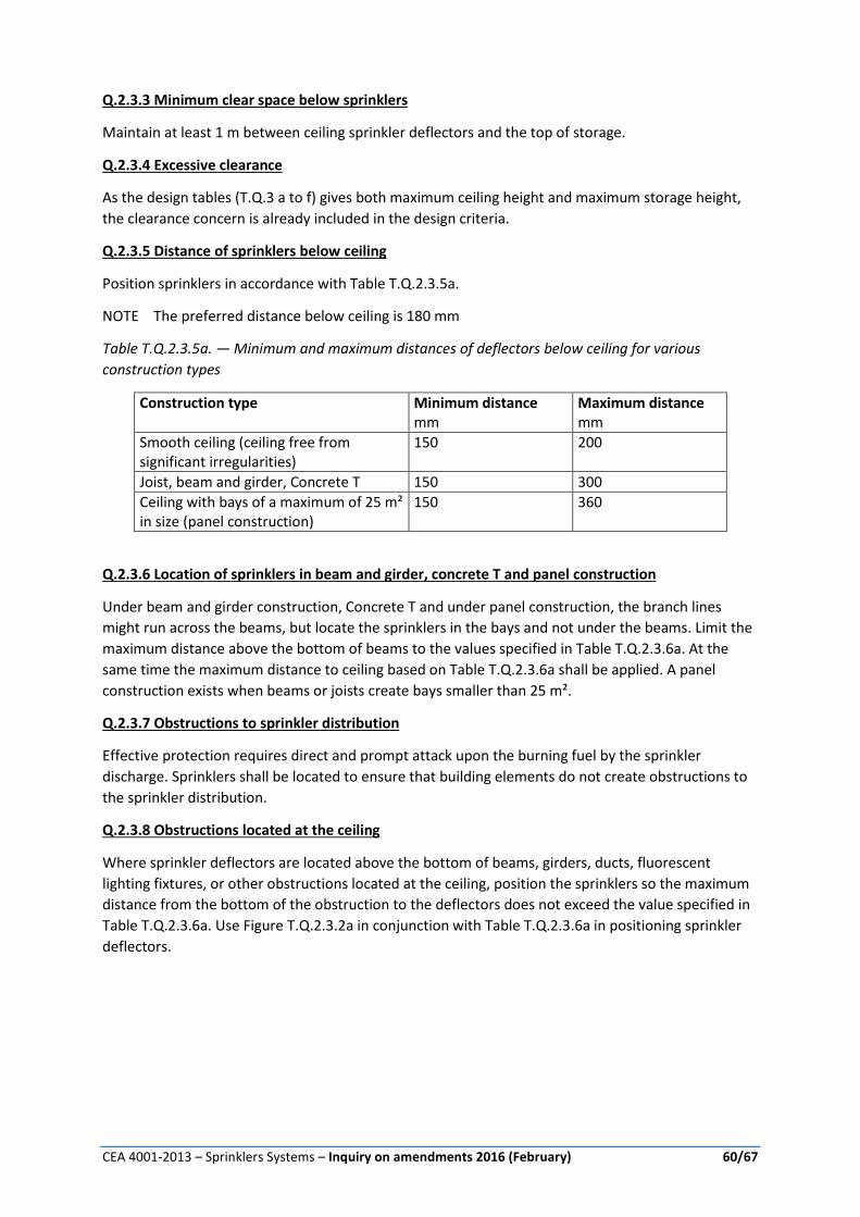
CEA 4001-2013 – Sprinklers Systems – Inquiry on amendments 2016 (February) 60/67
Q.2.3.3 Minimum clear space below sprinklers
Maintain at least 1 m between ceiling sprinkler deflectors and the top of storage.
Q.2.3.4 Excessive clearance
As the design tables (T.Q.3 a to f) gives both maximum ceiling height and maximum storage height,
the clearance concern is already included in the design criteria.
Q.2.3.5 Distance of sprinklers below ceiling
Position sprinklers in accordance with Table T.Q.2.3.5a.
NOTE The preferred distance below ceiling is 180 mm
Table T.Q.2.3.5a. — Minimum and maximum distances of deflectors below ceiling for various
construction types
Construction type Minimum distance Maximum distance mm mm
Smooth ceiling (ceiling free from significant irregularities)
150 200
Joist, beam and girder, Concrete T 150 300
Ceiling with bays of a maximum of 25 m² in size (panel construction)
150 360
Q.2.3.6 Location of sprinklers in beam and girder, concrete T and panel construction
Under beam and girder construction, Concrete T and under panel construction, the branch lines
might run across the beams, but locate the sprinklers in the bays and not under the beams. Limit the
maximum distance above the bottom of beams to the values specified in Table T.Q.2.3.6a. At the
same time the maximum distance to ceiling based on Table T.Q.2.3.6a shall be applied. A panel
construction exists when beams or joists create bays smaller than 25 m².
Q.2.3.7 Obstructions to sprinkler distribution
Effective protection requires direct and prompt attack upon the burning fuel by the sprinkler
discharge. Sprinklers shall be located to ensure that building elements do not create obstructions to
the sprinkler distribution.
Q.2.3.8 Obstructions located at the ceiling
Where sprinkler deflectors are located above the bottom of beams, girders, ducts, fluorescent
lighting fixtures, or other obstructions located at the ceiling, position the sprinklers so the maximum
distance from the bottom of the obstruction to the deflectors does not exceed the value specified in
Table T.Q.2.3.6a. Use Figure T.Q.2.3.2a in conjunction with Table T.Q.2.3.6a in positioning sprinkler
deflectors.

CEA 4001-2013 – Sprinklers Systems – Inquiry on amendments 2016 (February) 61/67
Figure F.Q.2.3.6a — Position of deflector when located above bottom of beam or other obstruction
located at the ceiling
Table T.Q.2.3.6a — Position of deflector when located above bottom of beam, joist or other
obstruction
Distance (a) Maximum distance from underside of beam/joist (b)
Less than 0,3 m 0 mm
0,3 m to less than 0,5 m 40 mm
0,5 m to less than 0,6 m 80 mm
0,6 m to less than 0,8 m 140 mm
0,8 m to less than 0,9 m 200 mm
0,9 m to less than 1,1m 250 mm
1,1 m to less than 1,2 m 300 mm
1,2 m to less than 1,4 m 380 mm
1,4 m to less than 1,5 m 460 mm
1,5 m to less than 1,7 m 560 mm
1,7 m to less than 1,8 m 660 mm
1,8 m 780 mm
Q.2.3.9 Obstructions located below the sprinklers
Position sprinklers with respect to fluorescent lighting fixtures, ducts, and other obstructions located
entirely below the sprinklers so the minimum horizontal distance from the near side of the
obstruction to the centre of the sprinkler is not less than the value specified in Table T.Q.2.3.9a, as
illustrated in Figure F.Q.2.3.9a. If obstruction is combustible and sprinklers are positioned so that the
combustible obstruction is not protected, provide additional protection. For this purpose lesser K-
Factor sprinklers with same temperature rating are permitted.
a
b
KeyD Deflector b Distance from underside of beam/joista Distance from beam/joist
D
a
b
KeyD Deflector b Distance from underside of beam/joista Distance from beam/joist
D

CEA 4001-2013 – Sprinklers Systems – Inquiry on amendments 2016 (February) 62/67
Figure F.Q.2.3.9a — Position of sprinkler in relation to obstructions located entirely below the
sprinklers
Key: D Deflector a Distance to Side of Obstruction b Distance Deflector Above Bottom of Obstruction
Table F.Q.2.3.9a — Position of sprinklers in relation to obstructions located entirely below the
sprinklers
Distance deflector above bottom of obstruction
Minimum distance to side of obstruction
Less than 150 mm 0,5 m
150 mm to less than 300 mm 0,9 m
300 mm to less than 460 mm 1,2 m
460 mm to less than 610 mm 1,5 m
610 mm to less than 760 mm 1,7 m
760 mm to less than 910 mm 1,8 m
When the bottom of the obstruction is located 1 m or more below the sprinkler deflectors, position
sprinklers so that the obstruction is centred between adjacent sprinklers, as shown in
Figure F.Q.2.3.9b.
For obstruction less than 600 mm width, the extension to either side of the midpoint between
sprinklers might not exceed 300 mm. Maintain at least an 460 mm clearance between the top of
storage and the bottom of the obstruction. If the extension to either side of the midpoint between
sprinklers exceed 300 mm, install one or more lines of sprinklers below obstructions.
For obstruction 600 mm width and above, install one or more lines of sprinklers below obstructions.
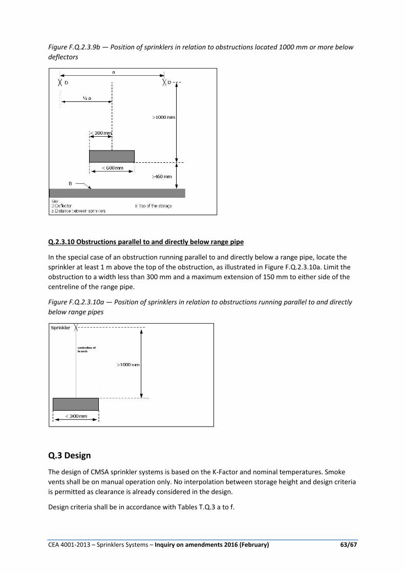
CEA 4001-2013 – Sprinklers Systems – Inquiry on amendments 2016 (February) 63/67
Figure F.Q.2.3.9b — Position of sprinklers in relation to obstructions located 1000 mm or more below
deflectors
Q.2.3.10 Obstructions parallel to and directly below range pipe
In the special case of an obstruction running parallel to and directly below a range pipe, locate the
sprinkler at least 1 m above the top of the obstruction, as illustrated in Figure F.Q.2.3.10a. Limit the
obstruction to a width less than 300 mm and a maximum extension of 150 mm to either side of the
centreline of the range pipe.
Figure F.Q.2.3.10a — Position of sprinklers in relation to obstructions running parallel to and directly
below range pipes
Q.3 Design
The design of CMSA sprinkler systems is based on the K-Factor and nominal temperatures. Smoke
vents shall be on manual operation only. No interpolation between storage height and design criteria
is permitted as clearance is already considered in the design.
Design criteria shall be in accordance with Tables T.Q.3 a to f.

CEA 4001-2013 – Sprinklers Systems – Inquiry on amendments 2016 (February) 64/67
Table T.Q.3a — Protection of indoor storage ST1 of Idle Wood Pallets
Nominal K-Factor
Maximum storage height
Maximum ceiling height
Type of system
Number of design sprinklers by minimum pressure in bar
Duration Tempe-rature
1.5 bar
1.7 bar
2,1 bar
3.5 bar
m m min
160 6,1 10,7 Wet 15 90 68 °C
Dry 25 120 141 °C
240 6,1 10,7 Wet 15 90 68 °C
Dry 25 120 141°C
280 6,1 10,7 Wet 15 90 68 °C
280 6,1 12,2 Wet 15 90 141 °C
Table T.Q.3b — Protection of idle plastic pallets (ST1)
Nominal K-Factor
Maximum storage height
Maximum ceiling height
Type of system
Number of design sprinklers by minimum pressure in bar
Duration Tempe-rature
1.5 bar 3.5 bar m m min
160 3,0 7,6 Wet 25 120 68 °C
240 3,0 7,6 Wet 25 120 68 °C
Table T.Q.3c — Design criteria for free standing storage (ST 1) of HHS1, HHS2 and HHS3 excluding
plastics
Commodity Max Storage height
Max ceiling
K-factor
Type Number of Sprinklers
Pressure Duration
Tempe-rature
m m bar min
HHS1/ HHS2
7,6 9,1
280 Wet 15
1,1
90 68 °C 9,1 10,7 1,7
10,7 12,2 2,1
HHS1/ HHS2
9,1 15,2
160 Wet 15 1,7 90 68 °C
Dry 25 1,7 120 141 °C
240 Wet 15 1,0 90 68 °C
Dry 25 1,0 120 141 °C
HHS3*
160 Wet 20 3,5 120 68 °C
Dry 25 3,5 120 141 °C
240 Wet 20 1,5 120 68 °C
Dry 25 1,5 120 141 °C
* less than 5 % expanded and unexpanded plastic (PE,PS,PP) per storage unit.

CEA 4001-2013 – Sprinklers Systems – Inquiry on amendments 2016 (February) 65/67
Table T.Q.3d — Design criteria for free standing storage (ST 1) of HHS 3 and HHS 4.
Commodity Max Storage height
Max ceiling height
K-factor Type Number of Sprinklers
Pressure in bar
Duration Tempe-rature
m m min
HHS 3
6,1 12,2
160 Wet 15 3,5 90 68 °C
Dry 25 3,5 120 141 °C
240 Wet 15 1,5 90 68 °C
Dry 25 3,5 120 141 °C
HHS3
7,6 9,1
160 Wet 20 3,5 120 68 °C
Dry 30 3,5 120 141 °C
240 Wet 15 1,5 90 68 °C
Dry 25 1,5 120 141 °C
HHS3 excluding expanded plastic
6,1 9,1
280 Wet 15
1,1
90 68 °C
6,1 10,7 1,7
6,1 12,2 2,1
7,6 9,1 1,1
7,6 10,7 1,7
7,6 12,2 2,1
9,1 10,7 1,7
10,7 12,2 2,1
HHS4 Excluding rubber tyres
6,1 9,1 160 Wet 25 3,5 120 68 °C
240 Wet 25 1,5 120 68 °C
HHS4 Excluding rubber tyres
4,6 10,7 160 Wet 25 3,5 120 68 °C
240 Wet 25 1,5 120 68 °C
Table T.Q.3e — Design criteria for single, double, and multiple-row racks for palletized rack storage (ST4) of HHS1, HHS2 and HHS 3 commodities excluding plastics
Commodity Max Storage height
Max. ceiling height
K-factor Type Number of Sprinklers
Pressure Duration Tempe-rature
m m bar min
HHS1
6,1 12,2
160 Wet 15 1,7 90 68 °C
Dry 25 1,7 120 141 °C
240 Wet 15 1,0 90 68 °C
Dry 25 1,0 120 141 °C
7,6 13,7
160 Wet 20 2,8 120 68 °C
Dry 30 2,8 120 141 °C
240 Wet 20 1,4 120 68 °C
Dry 30 1,4 120 141 °C
10,7 12,2
160 Wet 36a 3,8 120 68 °C
Dry 36a 3,8 120 141 °C
240 Wet 36a 1,5 120 68 °C
Dry 36a 1,5 120 141 °C
HHS2 6,1 12,2 160
Wet 15 1,7 90 68 °C
Dry 25 1,7 120 141 °C
240 Wet 15 1,0 90 68 °C
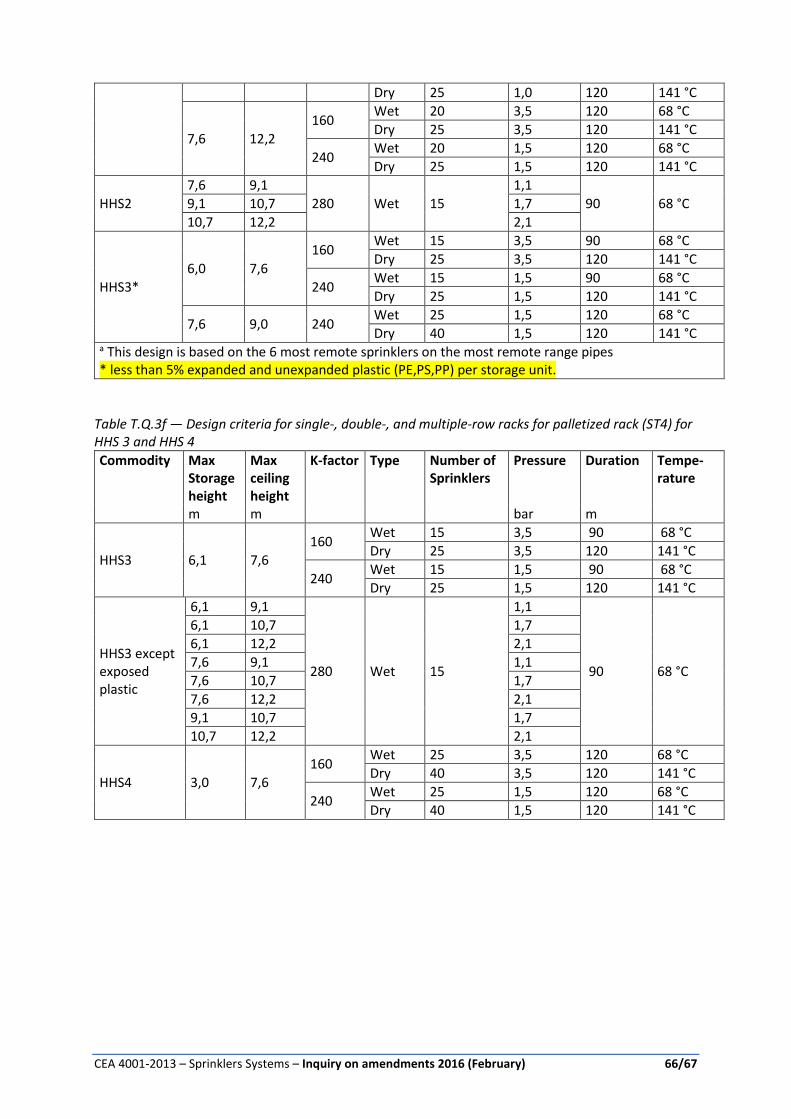
CEA 4001-2013 – Sprinklers Systems – Inquiry on amendments 2016 (February) 66/67
Dry 25 1,0 120 141 °C
7,6 12,2
160 Wet 20 3,5 120 68 °C
Dry 25 3,5 120 141 °C
240 Wet 20 1,5 120 68 °C
Dry 25 1,5 120 141 °C
HHS2
7,6 9,1
280 Wet 15
1,1
90 68 °C 9,1 10,7 1,7
10,7 12,2 2,1
HHS3*
6,0 7,6
160 Wet 15 3,5 90 68 °C
Dry 25 3,5 120 141 °C
240 Wet 15 1,5 90 68 °C
Dry 25 1,5 120 141 °C
7,6 9,0 240 Wet 25 1,5 120 68 °C
Dry 40 1,5 120 141 °C a This design is based on the 6 most remote sprinklers on the most remote range pipes * less than 5% expanded and unexpanded plastic (PE,PS,PP) per storage unit.
Table T.Q.3f — Design criteria for single-, double-, and multiple-row racks for palletized rack (ST4) for HHS 3 and HHS 4
Commodity Max Storage height
Max ceiling height
K-factor Type Number of Sprinklers
Pressure Duration Tempe-rature
m m bar m
HHS3 6,1 7,6
160 Wet 15 3,5 90 68 °C
Dry 25 3,5 120 141 °C
240 Wet 15 1,5 90 68 °C
Dry 25 1,5 120 141 °C
HHS3 except exposed plastic
6,1 9,1
280 Wet 15
1,1
90 68 °C
6,1 10,7 1,7
6,1 12,2 2,1
7,6 9,1 1,1
7,6 10,7 1,7
7,6 12,2 2,1
9,1 10,7 1,7
10,7 12,2 2,1
HHS4 3,0 7,6
160 Wet 25 3,5 120 68 °C
Dry 40 3,5 120 141 °C
240 Wet 25 1,5 120 68 °C
Dry 40 1,5 120 141 °C

CEA 4001-2013 – Sprinklers Systems – Inquiry on amendments 2016 (February) 67/67
CNPP Service Éditions [email protected]
CEA 4001-2013 – Sprinklers Systems – Inquiry on amendments 2016 (February)
All comments and suggestions will be studied by GEI4 and adjustments will be done where appropriate.
Name: Company:
Proposal Comments and suggestions
PROPOSAL n° 1 – Modification of Chapter 1
PROPOSAL n° 2 – Modification of Chapter 8
PROPOSAL n° 3 – Modification of Chapter 9
PROPOSAL n° 4 – Modification of Chapter 10
PROPOSAL n° 5 – Modification of Chapter 11
PROPOSAL n° 6 – Modification of Chapter 13.6
PROPOSAL n° 7 – Modification of Chapter 15
PROPOSAL n° 8 – Modification of Chapter 18
PROPOSAL n° 9 – Modification of D3 and F7
PROPOSAL n° 10 – Modification of Annex K
PROPOSAL n° 11 – Modification of Annex L
PROPOSAL n° 12 – Introduction of a new
annex: ANNEX Q - Control Mode Specific
Application Sprinklers (CMSA)


![Ściany oddzielenia przeciwpożarowego oraz kompleksowe …vds-global.com/fileadmin/vds_publikationen/vds_2234pl_web.pdf · fldq\ rgg]lhohqld su]hflzsr *durzhjr rud] 9g6 so nrpsohnvrzh](https://img.dokumen.tips/doc/110x75/5c76e3ce09d3f2b0618c138a/sciany-oddzielenia-przeciwpozarowego-oraz-kompleksowe-vds-fldq-rgglhohqld.jpg)


