Embed Size (px)
Citation preview

Proposal for Continued Study of Paraffin Deposition Prediction
In Multiphase Flowlines and Wellbores
A Proposal Submitted to
Potential Project Oriented Consortium Participants
by
Dr. James P. Brill F. M. Stevenson Endowed Presidential Chair in Petroleum Engineering
Executive Director, Fluid Flow Projects Co-Principal Investigator, Paraffin Deposition JIP
and
Dr. Michael Volk
Manager, Research and Technology Development Co-Principal Investigator, Paraffin Deposition JIP
The University of Tulsa
July 1999

1
Proposal for Continued Study of Paraffin Deposition in Multiphase Flowlines and
Wellbores
Objective s
Utilize the current test facilities to enhance understanding of paraffin deposition in single and two-phase (gas-oil) flow. Conduct focused experiments to better understand various aspects of deposition physics. Utilize knowledge gained from experimental and modeling studies to enhance the computer programs developed in the previous JIP for predicting paraffin deposition in single and two-phase flow environments.
Del iverables
The following deliverables are scheduled during the first three projects of the consortium.
Project 1: Single-Phase Studies
1. Automated single-phase loop operated using Intellution’s Fix 32 control software.
2. Data for single-phase paraffin deposition tests conducted on three black oils.
3. Report describing single-phase enhanced deposition model.
4. Computer program that incorporates enhanced deposition model.
Project 2: Two-Phase Studies
5. Data from two-phase heat transfer studies. Report on enhancement and validation of two-phase heat transfer models.
6. Data for two-phase (gas-oil) deposition tests conducted in horizontal, vertical and limited inclined test sections.
7. Report describing two-phase deposition model enhancements.
8. Computer program that incorporates enhanced paraffin deposition and heat transfer models.
Project 3: Deposition Physics and Water Impact Studies
9. Single and two-phase data that provide an understanding of the aging process and shear strength of paraffin deposits.
10. Expansion of two-phase flow loop to permit oil-water and gas-oil-water testing.
11. Data for two-phase (oil-water) and three-phase (gas-oil-water) deposition tests.
2
12. Three reports – two reports describing the study results on deposition physics and one report describing the study results on the impact of water.
13. Report describing enhanced deposition model.
14. Computer programs that incorporate findings from oil-water, gas-oil-water and deposition physics studies into paraffin deposition model.
Signi f icance
Paraffinic hydrocarbon liquids, including both crude oils and condensates, will form a paraffin or paraffin solid phase when the temperature falls below the cloud point (or Wax Appearance Temperature) of the liquid. Once formed, the paraffin will deposit on the pipe wall and/or be transported with the fluids. Paraffin deposition in crude oil and gas condensate production systems is a major challenge for the economic development of oil and gas fields producing from cold environments encountered in deep water. The paraffin deposition problem can cause a loss of billions of dollars per year worldwide through the enormous cost of prevention and remediation, reduced or deferred production, well shut-ins, pipeline replacements and/or abandonments, equipment failures, extra horsepower requirements, and increased manpower needs.
As oil and gas production moves to deeper and colder water, subsea multiphase production systems become critical for economic feasibility. It will also become increasingly imperative to adequately identify the conditions for paraffin precipitation and predict paraffin deposition rates to optimize the design and operation of these multiphase production systems. Although several oil companies have paraffin deposition predictive capabilities for single-phase oil flow, these predictive capabilities are not suitable for the multiphase flow conditions encountered in most flowlines and wellbores.
New petroleum production horizons at water depths greater than 500m have driven industry to develop new technologies for preventing and controlling the deposition of petroleum paraffin. Traditional methods of management, prevention, and remediation have been established for many years.1, 2 The greater water depths mean lower temperatures, and longer and fewer production lines in deeper water make economic solutions to prevention, management, and remediation key to economic development of these new deep water resources.
The cost of remediation due to pipeline blockage from paraffin deposition is on the order of $200,000 when the water depth is 100m, but on the order of $1,000,000 when the remediation occurs in water depths near 400m. The cost is proportionally greater as development depth increases.3
Current JIP
In May 1995 the University of Tulsa formed a Joint Industry Project (JIP) for the purpose of studying paraffin deposition in multiphase flowing petroleum systems. Some 37 oil
3
and gas related companies and governmental agencies have participated in the JIP. The JIP is organized with extensive input from industry through five operating committees. Semi-annual Advisory Board meetings and quarterly progress reports ensure continuous input from industry. Research is conducted primarily by graduate students, post-Doctoral Research Associates and Visiting Scholars. Over the past four years, the University has reported progress on the experimental program and results of deposition experiments, primarily from a single Gulf of Mexico crude oil. An extensive experimental program was executed for the purpose of developing an understanding of paraffin deposition during single-phase flow prior to experimentation on deposition during multiphase flow.
Single-Phase Deposition Research
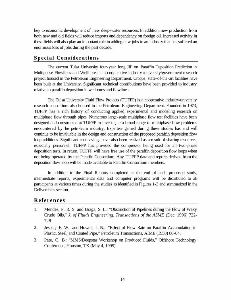
Over 20 single-phase deposition tests have been conducted in a 50-m long, 43.4-mm ID jacketed, near-horizontal flow loop that was moved to Tulsa from Canada and modified extensively before beginning tests. Key features of the enhanced flow loop are accurate temperature and pressure measurements every 5m, a thermostatic temperature jacket over the full 50-m length, progressing cavity oil pump, oil and coolant corriolis mass flow meters, precise inlet oil and coolant temperature control, and removable test sections (spool pieces) 20m from the entrance and 5m from the exit of the flow loop. Over 80 analog signals are logged with a Labview™ data acquisition system. Photographs of this facility are provided in Figures 1 to 4.
Paraffin deposition thickness was determined with four separate techniques. Accurate pressure drop measurements and roughness observations permit calculating reduction in pipe diameter as a result of deposition. Accurate temperature measurements permit performing an energy balance, based on assumed deposit thermal conductivities, to calculate the deposit thickness required to yield necessary insulation benefits. Pulse-echo ultrasonic measurements for some of the tests provided information about the deposit at one location in the flow loop. Finally, volumetric displacement measurements, visual observations and deposit samples from the two spool pieces yielded valuable information.
Some general conclusions drawn from the single-phase studies are:
• The initial inlet temperature of the oil does not significantly alter the deposition rate.
• The greater the temperature difference between the oil and the wall (or coolant), the greater the deposition rate.
• No deposition was observed, aside from adsorption, without heat flow from the oil to the wall.
• Deposit aging (hardening) was observed and documented by the change in heat transfer characteristics and the trapped oil content of the deposit.
• The trapped oil content in the deposit for turbulent flow was significantly lower than for laminar flow.
4
Several recommendations for improving the flow loop before conducting additional single-phase tests were also made, including:
• Add a static mixer upstream from the oil inlet to ensure uniform temperature distribution in the oil.
• Improve electronic components in the instrumentation patch panel to eliminate sensitivity to room temperature fluctuations.
• Replace a valve in the coolant system to improve flow rate stability.
• Heat trace all pressure tap lines.
• Install a distributed data acquisition system such as Intellution Fix 32 to facilitate simultaneous data analysis, better control of selected variables, and automation of flow loop operation to permit much longer test times.
Deliverables from the single-phase deposition research include a state-of-the-art test facility, a thermodynamic analysis of the fluids tested, an initial single-phase deposition program developed by Conoco, extensive heat transfer literature searches, single-phase deposition data and an enhanced deposition program with a user friendly interface.
Two-Phase Deposition Research
A new flow loop was designed and constructed for the purpose of generating two-phase, gas-oil deposition data. The flow loop consists of a tower with an inclinable boom on which a U-shaped, thermostatic jacketed test section is attached. Tests have been conducted at inclination angles typical of both producing wells and pipelines. The deposition leg of the test section has a 23-m long, 2-in. inner diameter, stainless steel inner pipe. A glycol-water mixture is circulated countercurrent in the jacket to simulate a cold pipe wall on the sea floor. The entire system is insulated, thoroughly instrumented, and designed to operate at pressures between 300 and 1,000 psia. Data are logged with an Intellution Fix 32 data acquisition and control system. Photographs of this test facility are provided in Figures 5 to 11.
Single-phase oil experiments have been completed that verify consistency with tests conducted in the single-phase flow loop. Limited single-phase gas tests were also conducted to finalize operating procedures. Over 20 multiphase flow tests have been conducted at three inclination angles and most flow patterns. Observations from the preliminary multiphase tests conducted show.
For horizontal and near-horizontal flow:
• Paraffin deposition appeared to be flow pattern specific.
• For stratified flow, a soft deposit, similar to the one in single-phase laminar flow is observed; however, the deposit is only at the bottom of the pipe.

5
• The deposit in annular flow has a uniform thickness around the pipe circumference and is very hard.
• Intermittent flow results in a hard deposit, with the hardness increasing from the top to the bottom of the pipe.
• The transition from stratified to annular flow yields a paraffin deposit thickness of the same order of magnitude; however, there is a significant increase in deposit hardness for the higher superficial gas velocity annular flow tests.
• A transition from stratified to intermittent flow results in a lower deposit thickness, but yields a deposit that is significantly harder.
• The transition from intermittent to annular flow results in a thicker deposit, but without a significant change in the deposit hardness.
For vertical flow:
• Wax deposition also appeared to be flow pattern specific.
• For single-phase flow, an increase in oil velocity results in harder deposits, but with a lower deposit thickness. The nature and the extent of wax deposit thickness in vertical flow are equivalent with the ones in horizontal flow.
• The deposit in annular flow is uniform across the pipe circumference and very hard for low oil superficial velocity. But for high superficial mixture velocity, the deposit is not as hard and the wax thickness is not as thick.
• Intermittent flow results in a medium hard to a hard deposit with uniform hardness around the pipe circumference. An increase in gas superficial velocity results in harder deposits, and it yields a wax deposit of the same order of magnitude.
• Transition from intermittent to annular flow yields a wax deposit of the same order of magnitude; however, there is no significant change in the deposit hardness.
• High oil superficial velocity or high superficial mixture velocity bubbly flow results in a hard deposit.
• Transition from bubbly flow at high oil superficial velocity to intermittent flow at low oil superficial velocity results in a thicker deposit and a significant decrease in its hardness.
• Transition from bubbly flow at high oil superficial velocity to intermittent flow yields a wax deposit of the same order of magnitude, however, there is no change in the deposit hardness.
A two-phase flow deposition program has been written and verified for single-phase oil flow by comparison with both the initial Conoco program and with experimental data. The program is fully compositional, contains modern mechanistic models for two-phase flow behavior, incorporates state of the art two-phase flow heat transfer correlations, and initial

6
concepts about two-phase deposition models. The program will be enhanced during the remainder of the JIP, using newly acquired two-phase flow deposition data.
Deliverables from the two-phase deposition research include a state-of-the-art multiphase test facility, an initial version of the two-phase flow computer program with a user-friendly interface, two-phase deposition data, and a two-phase flow computer program containing improved deposition models and heat transfer predictions.
From the studies conducted during the JIP it has become clear that a much broader collection of single-phase and two-phase experimental data, including other oil samples, will be necessary to develop appropriate paraffin deposition models. Additional research will also be necessary to fully understand some of the very complex mechanisms involved with paraffin deposition, such as aging phenomena, shear stripping, boundary layer phenomena, paraffin crystal properties, etc.
Proposed New Consort ium
On September 25, 1998 a workshop was hosted by The University of Tulsa to seek industry guidance to identify and prioritize necessary future research upon completion of the current JIP, and help identify the most appropriate organizational structure to conduct this research. Eighteen oil companies participated in the workshop. The attendees were surveyed and the rank-ordered responses for future uses of the existing paraffin deposition facilities are shown below:
1. Conduct additional gas-oil tests
2. Study effect of shear stripping
3. Conduct additional oil tests
4. Study the effects of aging
5. Conduct gas-oil-water tests
6. Quantify oil concentration in paraffin deposits
7. Conduct collaborative studies
8. Conduct hydrate and asphaltene tests
9. Conduct oil-water tests
10. Develop high pressure-high temperature flow pattern maps
11. Utilize loop for contract work
Other possible uses mentioned include:
12. Scale-up studies
13. Determine roughness of paraffin deposits

7
14. Conduct experiments with lower temperature gradients to determine effects of crystallization
15. Test instruments for measuring paraffin thickness
16. Determine thermal conductivity of the paraffin deposit
17. Pigging studies
18. Evaluate chemical inhibitors
19. Mechanistic model development
20. Multiphase heat transfer studies
Half of the participants in the survey felt that additional research should be conducted via a JIP while the other half felt it should be conducted via a consortium. Thirty-nine percent of the responders felt the fee should be $20,000 per year while forty-nine percent felt it should be $30,000 per year or more. Based on input from this survey, a Project Oriented Paraffin Deposition Consortium will be established in which the fee for industrial participants will be $30,000 per year. This new organization structure will permit the University to pursue a three-year evolving consortium business plan. This structure will allow timely graduate student recruiting while at the same time satisfying the industrial need of being project focused.
The target date to start the new consortium will be January 1, 2000, but the actual commencement date will be when the 14th participant executes the Letter of Agreement. The Letter of Agreement that will be used with all industry participants appears in the Appendix. The agreement with the DOE will be through a special research contract.
Scope of Work
Two state-of-the-art test facilities, P&ID shown in Figure 12, were developed for use in the current JIP. These facilities were used to generate high-quality data. It is proposed that these facilities be utilized to gather large quantities of single and multiphase flow data to enhance the capabilities of the predictive models during the first three years of the Project Oriented Paraffin Deposition Consortium. The work plan for this Project Oriented Paraffin Deposition Consortium shows the project beginning with three projects (Project 1 – conduct a large number of single-phase flow tests to more accurately model the single-phase deposition process; Project 2 – conduct a large number of two-phase flow tests to more accurately model the two-phase deposition process and Project 3 – focused experiments that would shed light on various aspects of deposition physics and the effect of water). The task schedules for Projects 1-3 are described below.
Project 1: Additional Single-Phase Oil Tests
In general, the effects of oil temperature and the difference between the oil and coolant temperatures on deposition rate can be predicted with a molecular diffusion model. However, no deposition model exists that can account for the effects of flow rate and aging, and predict
8
trapped oil content and thermal conductivity of deposits. It is clear from the experiments conducted in the current Paraffin JIP that neither shear dispersion nor molecular diffusion can adequately predict all the paraffin deposition phenomena that were observed. More basic research is needed, as is a larger, more diverse database.
The first project conducted in the new consortium will include tasks that must be completed to gain a better understanding of paraffin deposition in single-phase flow. An MS student and a visiting Scholar sponsored by Elf will conduct the flow loop experiments. The tasks for this project include automating the single-phase flow loop, conducting additional single-phase paraffin deposition tests, and enhancing the existing single-phase model to be less dependent on a specific oil. Each of these tasks is discussed in greater detail below.
Test Facility Enhancement
While conducting the single-phase flow tests, a number of recommendations were made that would improve the flow loop, thereby enabling the operator to take higher quality single-phase data.
Objective: Modify the single-phase flow loop to enable obtaining higher quality data.
The modifications to the existing single-phase flow loop will take five months. A static mixer will be added to eliminate the non-uniform temperature distributions observed during laminar testing. Existing manual valves will be replaced with computer controlled valves. The data acquisition system will be changed to Intellution Fix 32 Control software that will enable the tests to be automated and also permit simultaneous analysis of data. Temperature sensitive components in the instrument patch panel will be replaced and the pressure tap lines in the test section will be heat traced.
Single-Phase Paraffin Deposition Tests
Objective: Use the flow loop to obtain single-phase test data on three oils: the South Pelto black oil, the Garden Banks condensate and a black oil from the Rocky Mountain Oil Technology Center (RMOTC) that is currently planned for use in a DeepStar study.
The single-phase flow tests will generate new data for making improvements to the existing single-phase paraffin deposition model. They will also provide a better understanding of flow regime dependence, the effect of lower temperature gradients on paraffin crystal properties, and provide insight into deposit aging (much longer running times), shear stripping, mechanical strength, roughness and trapped oil concentration.
Use of the RMOTC crude oil depends on whether this oil is indeed used in future tests planned by both Texaco (4-in. flow loop) and DeepStar (possible 6-in. flow loop). These data would provide valuable scale-up information when compared with data from TU (1.7-in. flow loop).
9
Single-Phase Model Enhancements
Objective: Modify the current single-phase model to minimize the dependency on a single crude oil.
After the single-phase flow paraffin deposition model enhancements are made, the computer program will be turned over to a software company, such as MSI, to enhance the user-friendly graphical user interface.
Project 2: Additional Gas-Oil Tests
Tests have been conducted using South Pelto crude oil and natural gas at a pressure of 350 psia (24 bars). Ten tests have been conducted with the loop in a horizontal configuration (0o), six in a vertical configuration (90o) and three uphill and three downhill tests (+2o and –1o). The test conditions included one inlet two-phase mixture temperature and one inlet coolant temperature. Additional gas-oil test data are needed to adequately model paraffin deposition in two-phase flow.
The second project conducted in the new consortium will include tasks that must be completed to gain a more in-depth understanding of paraffin deposition in two-phase flow. A Ph.D. student and a Post Doctoral Research Associate will conduct this project. The tasks for this project include upgrading the flow loop, development of a mechanistic heat transfer model, conducting numerous additional two-phase paraffin deposition tests, and enhancing the existing two-phase model developed in the current Paraffin JIP.
Test Facility Upgrade
Objective: Modify the two-phase flow loop to enable obtaining higher quality data as well as permit long (days) term testing.
The modifications to the existing two-phase flow loop will take three months. Piping modifications will be made that will allow for feed gas injection at a constant flow rate throughout the duration of a test in order to maintain a constant system pressure. Piping changes will also be made that will allow gas that accumulates in the oil tank to be transferred to the receiver, thereby allowing the oil in the separator to be at a relatively constant level during a long duration test. A LabView™ based data acquisition system will be added to supplement the existing data acquisition system. This will allow fast data acquisition rates for the gamma densitometer and selected other signals.
Mechanistic Heat Transfer Model Development
Objective: Conduct heat transfer studies and develop flow pattern dependent mechanistic heat transfer model.
The model that is developed will be transformed into a computer code. The model predictions will be compared to the experimental data gathered. If necessary, the model will be refined and/or enhanced. The final model will be integrated into the existing two-phase deposition computer program.
10
Two-Phase Paraffin Deposition Tests
Objective: Use the test facility to obtain additional two-phase deposition data using the South Pelto crude oil.
The two-phase flow tests will generate additional deposition data with the test section in the horizontal, vertical and limited inclined positions. The two-phase flow tests will generate additional data for making improvements to the existing two-phase paraffin deposition model. They will also provide a better understanding of flow pattern dependence, flow regime (laminar vs. turbulent) dependence, the effect of lower temperature gradients on paraffin crystal properties, and provide insight into deposit aging (much longer running times), shear stripping, roughness and trapped oil concentration.
Two-Phase Model Enhancements
Objective: Modify the current two-phase model to more accurately predict paraffin deposition in a two-phase flow environment.
After the two-phase flow paraffin deposition model enhancements are made, the computer program will be turned over to a software company, such as MSI, to enhance the user-friendly graphical user interface.
Project 3 - Deposition Physics and Water Impact Studies
Objective: Conduct focused experiments to better understand various aspects of deposition physics and the effect of water on deposition.
Previous single-phase flow studies have identified issues such as how the composition of the deposit changes with time or what the shear mechanics are along the pipe wall. By isolating phenomena such as these, an understanding of the deposition physics will be gained. The term deposition physics is used to denote the many phenomena beyond molecular diffusion that influence paraffin deposition. Other issues such as the impact on the deposition rate from adding water are not well understood. The findings from studies such as these will be incorporated into the model for predicting paraffin deposition. Specific studies within Project 3 are listed below; however, discussions will be held with the participants and the scope of the studies will be finalized before they are commenced.
Study 3: Single-Phase Paraffin Properties
Spool Piece Modification
Objective: Modify both single-phase spool pieces to allow taking samples as a function of time.
Design, development and testing will take seven months. It is envisioned that a retractable coupon sampler will be installed. A prototype system will be developed and tested. Necessary modifications will be made and two spool pieces will be built.
11
Single-Phase Paraffin Property Determination
Objective: Use the coupon sampler to determine physical properties of paraffin samples as a function of time.
The coupon sampler will provide samples that once analyzed will provide insight into the aging process and the mechanical strength of the paraffin deposit as a function of time. The results from these measurements will be used to make improvements to the existing single-phase model.
Single-Phase Model Enhancements
Objective: Modify the current single-phase model to more accurately account for aging and shear strength of paraffin deposits.
After the single-phase flow paraffin deposition model enhancements are made, the computer program will be turned over to a software company, such as MSI, to enhance the user-friendly graphical user interface.
Study b: Two-Phase Paraffin Properties
Objective: Analyze paraffin deposits after conducting long term tests (one week to one month in duration) to better understand the aging process as well as the layering effect observed in field deposits.
This study will investigate the aging process in two-phase flow by conducting deposition tests that are run for 5 days. The deposits will be analyzed for occluded oil. Some long-term tests (30 days) will be run to examine the layering effect observed in field samples and long term aging. Samples will be taken from each layer and analyzed for occluded oil, density, composition, shear strength, etc.
Two-Phase Model Enhancements
Objective: Modify the two-phase model to more accurately account for aging and the prediction of long term deposition.
After the two-phase flow paraffin deposition model enhancements are made, the computer program will be turned over to a software company, such as MSI, to enhance the user-friendly graphical interface.
Study c: Effects of Water on Paraffin Deposition
The third study in Project 3 will investigate the effects of water on paraffin deposition under multiphase flow conditions. This study will be conducted by an MS student and a Post Doctoral Research Associate. The tasks for this study include expanding the gas-oil deposition flow loop to handle a third phase (water), and conducting two and three-phase paraffin deposition tests. Each of these tasks is discussed in greater detail below.
12
Flow Loop Expansion
Objective: Modify the two-phase flow loop to accommodate water
Expansion of the two-phase flow loop will take five months. A second Moyno pump will be added and a water-oil separation facility will be designed and installed. Automated valves will be purchased and the piping and associated instrumentation installed. The entire water facility will be insulated.
Two and Three-Phase Paraffin Deposition Tests
Objective: Conduct a sufficient number of two-phase (oil-water) and three-phase (gas-oil-water) tests using the South Pelto crude oil to provide an understanding of the impact water has on paraffin deposition in a multiphase flow environment.
The oil-water and gas-oil-water tests will be conducted with the flow loop in a horizontal position. At least two water cuts will be used. These multiphase flow tests will generate unique data that will be utilized in developing a preliminary understanding of the deposition process when water is present in flowlines and wellbores. These tests will also provide some insight on shear stripping, roughness and occluded oil concentration in paraffin. The need to conduct more extensive tests in a follow-on investigation will be evaluated.
Project Timetable
The schedule for completing each of the initial projects in the new consortium is shown in Figures 13 - 15. The estimated time duration for each of the tasks is identified. Planning for the projects began in September 1998 and will continue until January 1, 2000, when the Project Oriented Consortium is scheduled to begin. Figures 13 - 15 also identify when significant deliverables in the form of reports, models and data that will be distributed to the participants.
It is envisioned that this consortium will continue past the first three years of study. Upon completion of each study year, the project timetable will be expanded to accommodate studies identified during the ongoing research or brought forth by participants.
Estimated Cost and Sources of Support
Projected manpower requirements for the first three years of study are identified in Table 1, together with salaries, indirect costs, fringe benefits, miscellaneous costs and costs related to test facility design, modification and/or construction. A breakout of the estimated man months and salaries by study is provided in Table 2a-e and Table 3 and are presented graphically in Figures 16 - 17, respectively. The total cost for the first two projects and the two deposition physics studies and the water impact study is estimated to be $2,460,000.
It is proposed that the Consortium participants collectively pay 50% of the total cost for the first three studies and that the DOE pay the remaining 50%. This represents a twenty seven to one leveraging of participants R & D investment. These funds will aid Tulsa University in its
13
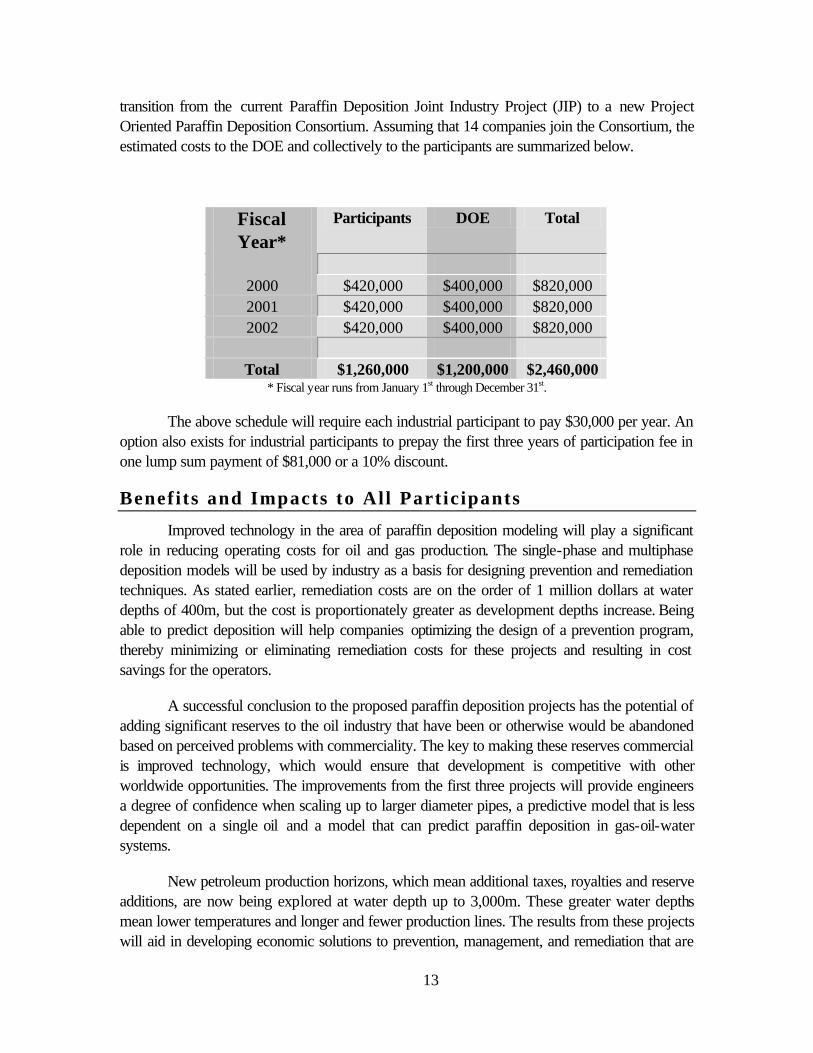
transition from the current Paraffin Deposition Joint Industry Project (JIP) to a new Project Oriented Paraffin Deposition Consortium. Assuming that 14 companies join the Consortium, the estimated costs to the DOE and collectively to the participants are summarized below.
Fiscal Year*
Participants DOE Total
2000 $420,000 $400,000 $820,000 2001 $420,000 $400,000 $820,000 2002 $420,000 $400,000 $820,000
Total $1,260,000 $1,200,000 $2,460,000
* Fiscal year runs from January 1st through December 31st.
The above schedule will require each industrial participant to pay $30,000 per year. An option also exists for industrial participants to prepay the first three years of participation fee in one lump sum payment of $81,000 or a 10% discount.
Benefits and Impacts to All Partic ipants
Improved technology in the area of paraffin deposition modeling will play a significant role in reducing operating costs for oil and gas production. The single-phase and multiphase deposition models will be used by industry as a basis for designing prevention and remediation techniques. As stated earlier, remediation costs are on the order of 1 million dollars at water depths of 400m, but the cost is proportionately greater as development depths increase. Being able to predict deposition will help companies optimizing the design of a prevention program, thereby minimizing or eliminating remediation costs for these projects and resulting in cost savings for the operators.
A successful conclusion to the proposed paraffin deposition projects has the potential of adding significant reserves to the oil industry that have been or otherwise would be abandoned based on perceived problems with commerciality. The key to making these reserves commercial is improved technology, which would ensure that development is competitive with other worldwide opportunities. The improvements from the first three projects will provide engineers a degree of confidence when scaling up to larger diameter pipes, a predictive model that is less dependent on a single oil and a model that can predict paraffin deposition in gas-oil-water systems.
New petroleum production horizons, which mean additional taxes, royalties and reserve additions, are now being explored at water depth up to 3,000m. These greater water depths mean lower temperatures and longer and fewer production lines. The results from these projects will aid in developing economic solutions to prevention, management, and remediation that are
14
key to economic development of new deep-water resources. In addition, new production from both new and old fields will reduce imports and dependency on foreign oil. Increased activity in these fields will also play an important role in adding new jobs to an industry that has suffered an enormous loss of jobs during the past decade.
Special Considerat ions
The current Tulsa University four-year long JIP on Paraffin Deposition Prediction in Multiphase Flowlines and Wellbores is a cooperative industry /university/government research project housed in the Petroleum Engineering Department. Unique, state-of-the-art facilities have been built at the University. Significant technical contributions have been provided to industry relative to paraffin deposition in wellbores and flowlines.
The Tulsa University Fluid Flow Projects (TUFFP) is a cooperative industry/university research consortium also housed in the Petroleum Engineering Department. Founded in 1973, TUFFP has a rich history of conducting applied experimental and modeling research on multiphase flow through pipes. Numerous large-scale multiphase flow test facilities have been designed and constructed at TUFFP to investigate a broad range of multiphase flow problems encountered by the petroleum industry. Expertise gained during these studies has and will continue to be invaluable in the design and construction of the proposed paraffin deposition flow loop additions. Significant cost savings have also been realized as a result of sharing resources, especially personnel. TUFFP has provided the compressor being used for all two-phase deposition tests. In return, TUFFP will have free use of the paraffin deposition flow loops when not being operated by the Paraffin Consortium. Any TUFFP data and reports derived from the deposition flow loop will be made available to Paraffin Consortium members.
In addition to the Final Reports completed at the end of each proposed study, intermediate reports, experimental data and computer programs will be distributed to all participants at various times during the studies as identified in Figures 1-3 and summarized in the Deliverables section.
References
1. Mendes, P. R. S. and Braga, S. L.: “Obstruction of Pipelines during the Flow of Waxy Crude Oils,” J. of Fluids Engineering, Transactions of the ASME (Dec. 1996) 722-728.
2. Jessen, F. W. and Howell, J. N.: “Effect of Flow Rate on Paraffin Accumulation in Plastic, Steel, and Coated Pipe,” Petroleum Transactions, AIME (1958) 80-84.
3. Pate, C. B.: “MMS/Deepstar Workshop on Produced Fluids,” Offshore Technology Conference, Houston, TX (May 4, 1995).
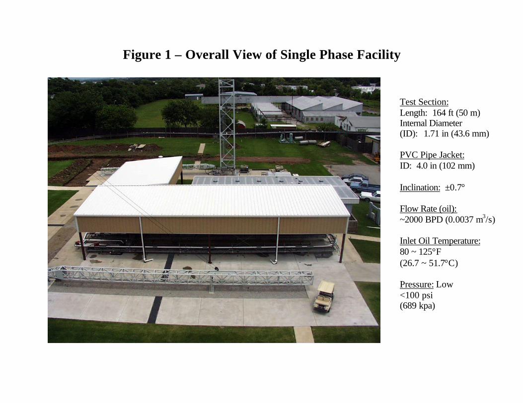
Figure 1 – Overall View of Single Phase Facility
Test Section: Length: 164 ft (50 m) Internal Diameter (ID): 1.71 in (43.6 mm) PVC Pipe Jacket: ID: 4.0 in (102 mm) Inclination: ±0.7° Flow Rate (oil): ~2000 BPD (0.0037 m3/s) Inlet Oil Temperature: 80 ~ 125°F (26.7 ~ 51.7°C) Pressure: Low <100 psi (689 kpa)
Figure 2 - Single Phase Flow Loop
Pressures: 2 Gauge Pressures (GP)
(beginning and end of test section)
9 Differential Pressures Temperatures: 10 Temperatures for glycol 10 Temperatures for oil 4 Temperatures for
reference sections 27 Temperatures inside
pipe for top, bottom and side, at nine different locations.
Trimmer: Current < 1500 amps Transformer: 10-kw Two Spool Pieces

Figure 3 - Single Phase Oil System
Tanks: Two 6.3 bbl each (1.0 m3) Pump: Moyno 4080 BPD (0.0075 m3/s) (<100 psi) Flow Meter: Micro Motion

• 50% glycol-water • 2000 BPD
(3.68x10⁻³ m3/s) • 40 ton Chiller
Figure 4 – Single Phase Cold Glycol System
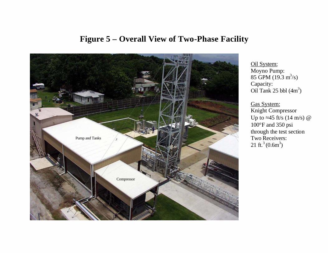
Figure 5 – Overall View of Two-Phase Facility
Oil System: Moyno Pump: 85 GPM (19.3 m3/s) Capacity: Oil Tank 25 bbl (4m3) Gas System: Knight Compressor Up to ≈45 ft/s (14 m/s) @ 100°F and 350 psi through the test section Two Receivers: 21 ft.3 (0.6m3)
Pump and Tanks
Compressor
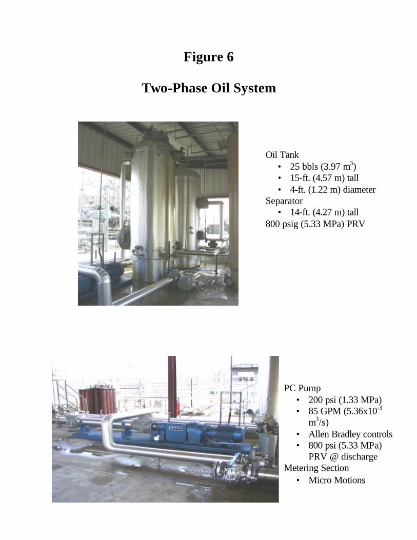
Figure 6
Two-Phase Oil System
PC Pump • 200 psi (1.33 MPa) • 85 GPM (5.36x10⁻³
m3/s) • Allen Bradley controls • 800 psi (5.33 MPa)
PRV @ discharge Metering Section
• Micro Motions
Oil Tank • 25 bbls (3.97 m3) • 15-ft. (4.57 m) tall • 4-ft. (1.22 m) diameter
Separator • 14-ft. (4.27 m) tall
800 psig (5.33 MPa) PRV
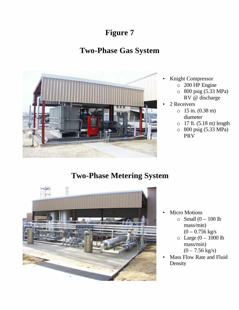
Figure 7
Two-Phase Gas System
• Knight Compressor o 200 HP Engine o 800 psig (5.33 MPa)
RV @ discharge • 2 Receivers
o 15 in. (0.38 m) diameter
o 17 ft. (5.18 m) length o 800 psig (5.33 MPa)
PRV
Two-Phase Metering System
• Micro Motions o Small (0 – 100 lb
mass/min) (0 – 0.756 kg/s
o Large (0 – 1000 lb mass/min) (0 – 7.56 kg/s)
• Mass Flow Rate and Fluid Density
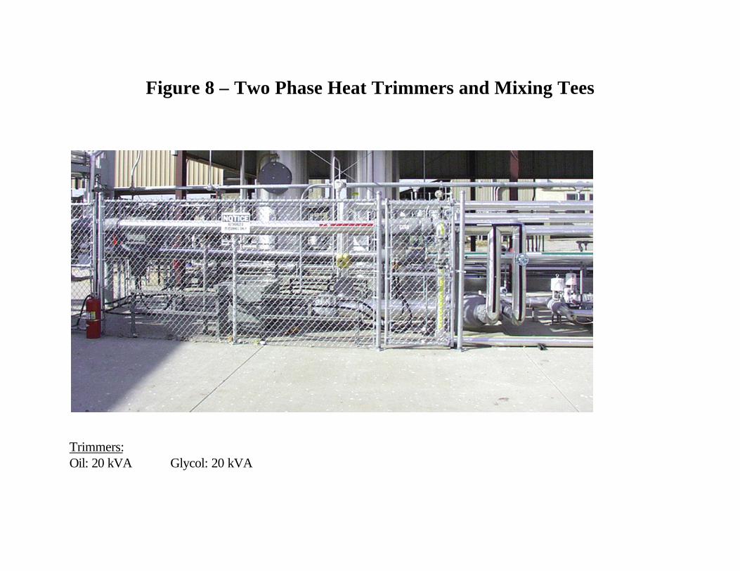
Figure 8 – Two Phase Heat Trimmers and Mixing Tees
Trimmers: Oil: 20 kVA Glycol: 20 kVA
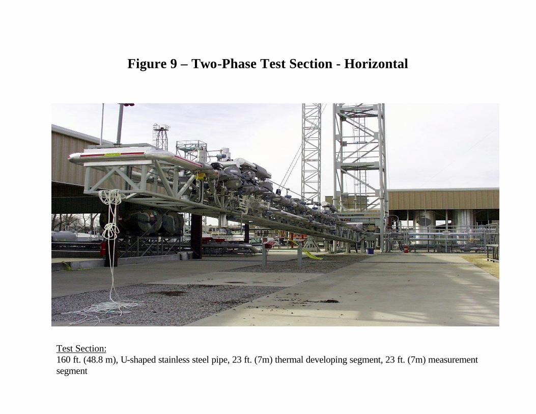
Figure 9 – Two-Phase Test Section - Horizontal
Test Section: 160 ft. (48.8 m), U-shaped stainless steel pipe, 23 ft. (7m) thermal developing segment, 23 ft. (7m) measurement segment
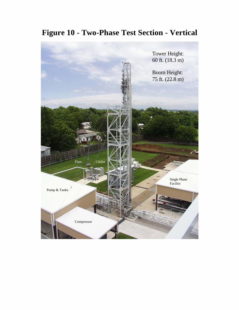
Figure 10 - Two-Phase Test Section - Vertical
Tower Height: 60 ft. (18.3 m) Boom Height: 75 ft. (22.8 m)
Pump & Tanks
Compressor
Single Phase Facility
Flare Chiller
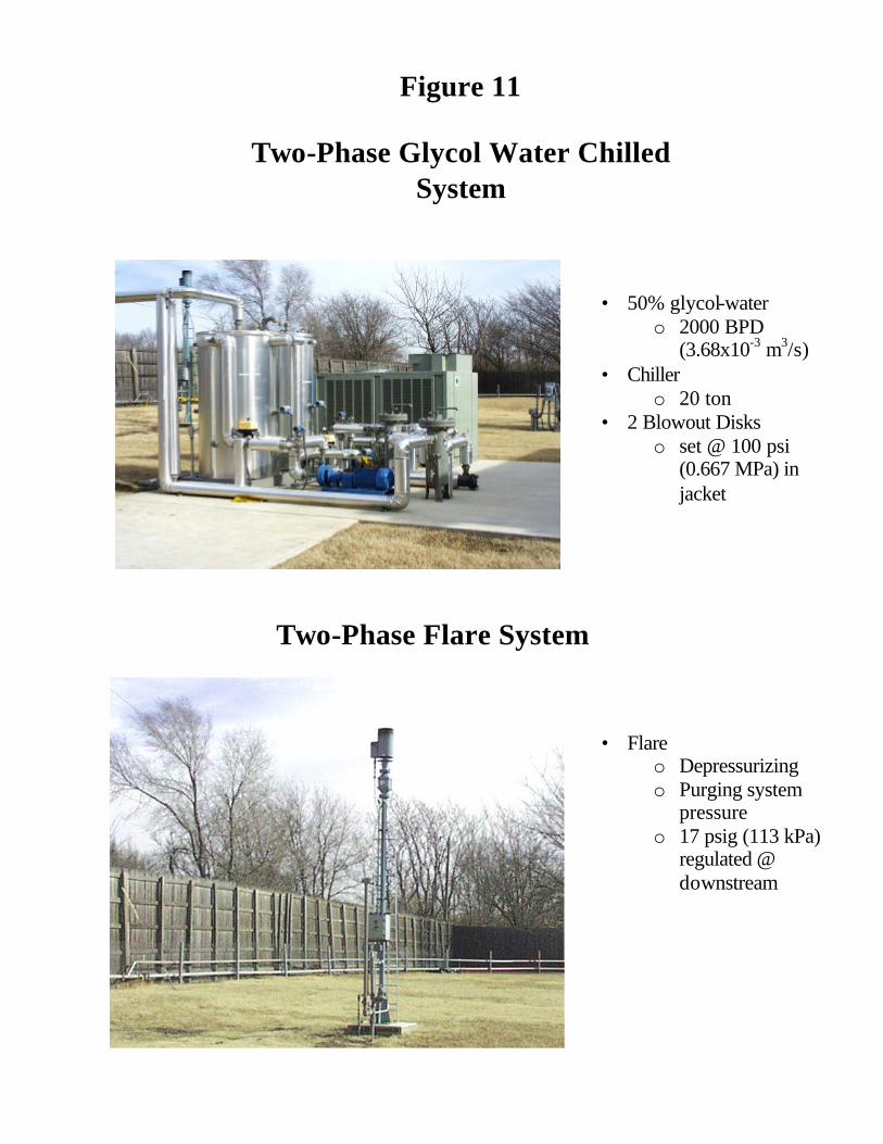
• 50% glycol-water o 2000 BPD
(3.68x10⁻³ m3/s) • Chiller
o 20 ton • 2 Blowout Disks
o set @ 100 psi (0.667 MPa) in jacket
• Flare
o Depressurizing o Purging system
pressure o 17 psig (113 kPa)
regulated @ downstream
Two-Phase Flare System
Figure 11
Two-Phase Glycol Water Chilled System

Figure 13: Paraffin Deposition Task Schedules Single-Phase Studies
Task J F M A M J J A S O N D J F M A M J J A S O N D J F M A M J J A S O N D
Project 1 - Additional Single Phase Tests
• Single-Phase Flow Loop Upgrade • South Pelto Oil Studies -Flow Regime Dependence -Effect of DT on Wax Crystals • Garden Banks Condensate Studies -Flow Regime Dependence -Aging -Shear Stripping, Roughness,Trapped Oil -Effect of DT on Wax Crystals • RMOTC Oil Studies -Flow Regime Dependence -Aging -Shear Stripping, Roughness,Trapped Oil -Effect of DT on Wax Crystals • Scale-up Comparisons • Deposition Model Enhancement • Final Report
2000 2001 2002
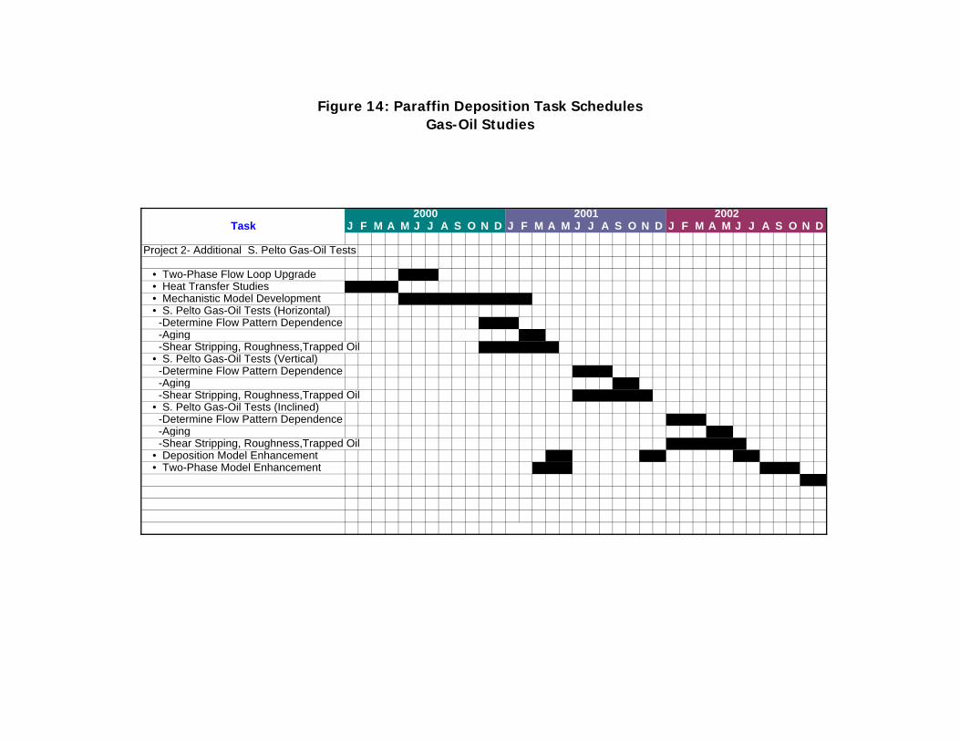
Figure 14: Paraffin Deposition Task Schedules Gas-Oil Studies
Task J F M A M J J A S O N D J F M A M J J A S O N D J F M A M J J A S O N D
Project 2- Additional S. Pelto Gas-Oil Tests
• Two-Phase Flow Loop Upgrade • Heat Transfer Studies • Mechanistic Model Development • S. Pelto Gas-Oil Tests (Horizontal) -Determine Flow Pattern Dependence -Aging -Shear Stripping, Roughness,Trapped Oil • S. Pelto Gas-Oil Tests (Vertical) -Determine Flow Pattern Dependence X X X -Aging X X -Shear Stripping, Roughness,Trapped Oil X X X X X X • S. Pelto Gas-Oil Tests (Inclined) -Determine Flow Pattern Dependence X X X -Aging X X -Shear Stripping, Roughness,Trapped Oil X X X X X X • Deposition Model Enhancement X X X X X X • Two-Phase Model Enhancement X X X X X X x x
2000 2001 2002
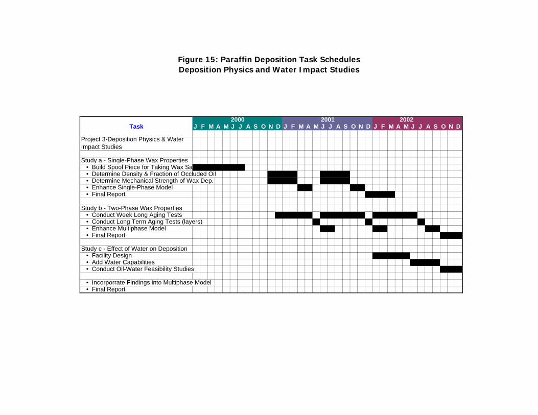
Figure 15: Paraffin Deposition Task Schedules Deposition Physics and Water Impact Studies
Task J F M A M J J A S O N D J F M A M J J A S O N D J F M A M J J A S O N D
Project 3-Deposition Physics & Water Impact Studies
Study a - Single-Phase Wax Properties • Build Spool Piece for Taking Wax Samples • Determine Density & Fraction of Occluded Oil • Determine Mechanical Strength of Wax Dep. • Enhance Single-Phase Model • Final Report
Study b - Two-Phase Wax Properties • Conduct Week Long Aging Tests • Conduct Long Term Aging Tests (layers) • Enhance Multiphase Model • Final Report
Study c - Effect of Water on Deposition • Facility Design • Add Water Capabilities • Conduct Oil-Water Feasibility Studies • Incorporrate Findings into Multiphase Model • Final Report
2000 2001 2002

Table 1: Paraffin Deposition Three Year Budget
Expense Category Year 1 Year 2 Year 3 Total
Salary, Fr, IDC Salary (3% Increases) 331,080$ 359,910$ 353,946$ ######## IDC @ 56% 185,405$ 201,549$ 198,209$ 585,163$ Fringe @ 31% 84,630$ 77,590$ 79,918$ 242,138$ Total Sal, Fr, IDC 601,115$ 639,049$ 632,073$ ########
Tuition (84 Hours) 14,400$ 21,600$ 7,200$ 43,200$
Equipment Single-Phase Flow Loop Upgrade 60,000$ 60,000$ Two-Phase Flow Loop Upgrade 10,000$ 10,000$ Deposition Physics Studies 50,000$ 80,000$ 90,000$ 220,000$ Total Flow Loop 120,000$ 80,000$ 90,000$ 290,000$ Outside Services PVT Analyses 5,000$ 5,000$ Electrical 5,000$ 5,000$ 10,000$ Insulation 5,000$ 5,000$ 10,000$ Total Subcontracts 10,000$ 5,000$ 10,000$ 25,000$
Miscellaneous Travel 10,000$ 10,000$ 10,000$ 30,000$ Adv Bd and Committee Meetings 8,000$ 8,000$ 10,000$ 26,000$ Office Supplies 5,000$ 5,000$ 8,000$ 18,000$ Research Supplies 20,000$ 20,000$ 20,000$ 60,000$ Maintenance 13,000$ 13,000$ 14,000$ 40,000$ Printing/Dup/Postage 8,000$ 8,000$ 8,000$ 24,000$ Computers/Software 8,000$ 8,000$ 8,000$ 24,000$ Telecommunications 2,000$ 2,000$ 2,000$ 6,000$ Total Miscellaneous 74,000$ 74,000$ 80,000$ 228,000$
Total 819,515$ 819,649$ 819,273$ ########
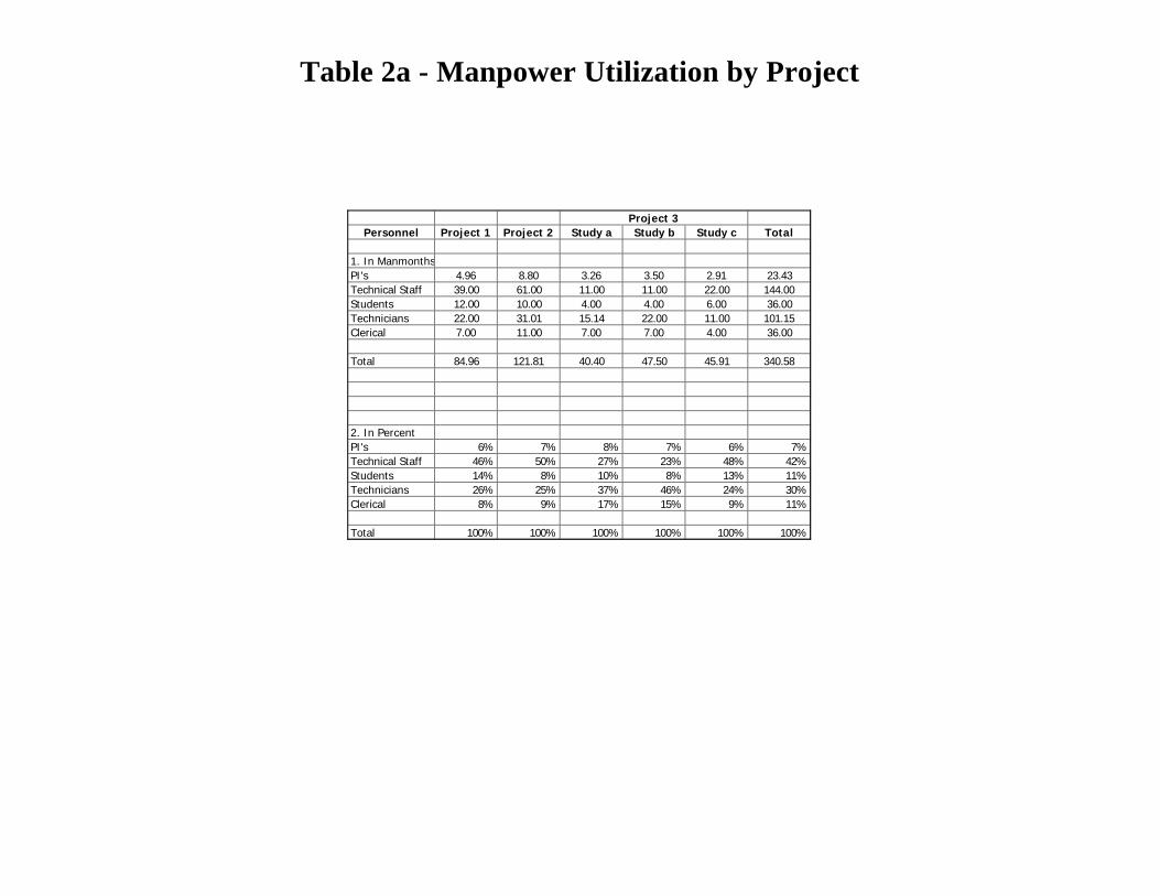
Table 2a - Manpower Utilization by Project
Personnel Project 1 Project 2 Study a Study b Study c Total
1. In ManmonthsPI's 4.96 8.80 3.26 3.50 2.91 23.43Technical Staff 39.00 61.00 11.00 11.00 22.00 144.00Students 12.00 10.00 4.00 4.00 6.00 36.00Technicians 22.00 31.01 15.14 22.00 11.00 101.15Clerical 7.00 11.00 7.00 7.00 4.00 36.00
Total 84.96 121.81 40.40 47.50 45.91 340.58
2. In PercentPI's 6% 7% 8% 7% 6% 7%Technical Staff 46% 50% 27% 23% 48% 42%Students 14% 8% 10% 8% 13% 11%Technicians 26% 25% 37% 46% 24% 30%Clerical 8% 9% 17% 15% 9% 11%
Total 100% 100% 100% 100% 100% 100%
Project 3

Table 2b - Total Manmonths for First Three Years of Wax Project
Personnel Project 1 Project 2 Study a Study b Study c Total
Full Time Employees PI 1.9 3 0.86 1 1.13 7.89 Co-PI 1.86 2.8 1.7 1.7 1.03 9.09 Post Doc 1 8 0 4 0 6 18 Post Doc 2 0 14 0 4 0 18 Mechanical Technician 6 5 2 2 3 18 Electronics Technician 6 5 2 2 3 18 Administrative 3.5 5.5 3.5 3.5 2 18 Clerical 3.5 5.5 3.5 3.5 2 18 G.C.Technician 7 11 7 7 4 36 Operator 1 (Single-phase Loop) 24 0 0 0 12 36 Operator 2 (Two-phase Loop) 0 36 0 0 0 36Subtotal 61.76 87.8 24.56 24.7 34.16 232.98 Part Time Employees Co-PI (Brill) 1.2 3 0.7 0.8 0.75 6.45Subtotal 1.2 3 0.7 0.8 0.75 6.45
Students MS 1- Single-Phase Tests 12 0 0 0 0 12 PhD- Two-Phase Tests 0 18 0 0 0 18 MS 2-Deposition Physics Study 1 0 0 12 0 0 12 MS 3-Deposition Physics Study 2 0 0 0 12 0 MS 4-Deposition Physics Study 3 0 0 0 0 6 Part Time 10 13.01 3.14 10 5 41.15Subtotal 22 31.01 15.14 22 11 101.15
Total 84.96 121.81 40.4 47.5 45.91 340.58
Project 3

Table 2c - Manmonths for Year 1 of Wax Project
Personnel Project 1 Project 2 Study a Study b Study c Total
Full Time Employees PI 1.2 1 0.43 2.63 Co-PI 1.03 1 1 3.03 Post Doc 1 4 2 6 Post Doc 2 6 6 Mechanical Technician 4 1 1 6 Electronics Technician 4 1 1 6 Administrative 2 2 2 6 Clerical 2 2 2 6 G.C.Technician 4 4 4 12 Operator 1 (Single-phase Loop) 12 12 Operator 2 (Two-phase Loop) 12 12Subtotal 34.23 30 13.43 77.66 Part Time Employees Co-PI (Brill) 0.8 1 0.35 2.15Subtotal 0.8 1 0.35 2.15
Students MS 1- Single-Phase Tests 6 6 PhD- Two-Phase Tests 6 6 MS 2-Deposition Physics Study 1 6 6 MS 3-Deposition Physics Study 2 MS 4-Deposition Physics Study 3 Part Time 5 4.29 1 10.29Subtotal 11 10.29 7 28.29
Total 46.03 41.29 20.78 0 0 108.1
Project 3
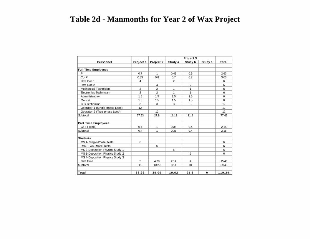
Table 2d - Manmonths for Year 2 of Wax Project
Personnel Project 1 Project 2 Study a Study b Study c Total
Full Time Employees PI 0.7 1 0.43 0.5 2.63 Co-PI 0.83 0.8 0.7 0.7 3.03 Post Doc 1 4 2 6 Post Doc 2 4 2 6 Mechanical Technician 2 2 1 1 6 Electronics Technician 2 2 1 1 6 Administrative 1.5 1.5 1.5 1.5 6 Clerical 1.5 1.5 1.5 1.5 6 G.C.Technician 3 3 3 3 12 Operator 1 (Single-phase Loop) 12 12 Operator 2 (Two-phase Loop) 12 12Subtotal 27.53 27.8 11.13 11.2 77.66 Part Time Employees Co-PI (Brill) 0.4 1 0.35 0.4 2.15Subtotal 0.4 1 0.35 0.4 2.15
Students MS 1- Single-Phase Tests 6 6 PhD- Two-Phase Tests 6 6 MS 2-Deposition Physics Study 1 6 6 MS 3-Deposition Physics Study 2 6 6 MS 4-Deposition Physics Study 3 Part Time 5 4.29 2.14 4 15.43Subtotal 11 10.29 8.14 10 39.43
Total 38.93 39.09 19.62 21.6 0 119.24
Project 3

Table 2e - Manmonths for Year 3 of Wax Project
Employee Project 1 Project 2 Study a Study b Study c Total
Full Time Employees PI 0 1 0.5 1.13 2.63 Co-PI 1 1 1.03 3.03 Post Doc 1 6 6 Post Doc 2 4 2 6 Mechanical Technician 2 1 3 6 Electronics Technician 2 1 3 6 Administrative 2 2 2 6 Clerical 2 2 2 6 G.C.Technician 4 4 4 12 Operator 1 (Single-phase Loop) 12 12 Operator 2 (Two-phase Loop) 12 12Subtotal 30 13.5 34.16 77.66 Part Time Employees Co-PI (Brill) 1 0.4 0.75 2.15Subtotal 1 0.4 0.75 2.15
Students MS 1- Single-Phase Tests 0 PhD- Two-Phase Tests 6 6 MS 2-Deposition Physics Study 1 0 MS 3-Deposition Physics Study 2 6 6 MS 4-Deposition Physics Study 3 6 6 Part Time 4.43 6 5 15.43Subtotal 10.43 12 11 33.43
Total 41.43 25.9 45.91 113.24
Project 3

Figure 16 - Manpower by Project
Total Manpower
PI's7%
Technical Staff41%
Students30%
Technicians11%
Clerical11%
Manpower for Project 1Single Phase Flow Loop Experiments
PI's6%
Technical Staff
46%Students
26%
Technicians14%
Clerical
8%
Manpower for Project 2Gas-Oil Experiments
PI's7%
Technical Staff51%
Students25%
Technicians8%
Clerical9%
Manpower for Project 3 Study bTwo-Phase Wax Properties
PI's
7%
Technical Staff23%
Students
47%
Technicians8%
Clerical
15%
Manpower for Project 3 Study cEffect of Water on Deposition
PI's6%
Technical Staff48%Students
24%
Technicians13%
Clerical9%
Manpower for Project 3 Study aSingle Phase Wax Properties
PI's
8%
Technical Staff
27%
Students38%
Technicians
10%
Clerical
17%

Table 3 - Salaries by Project
Personnel Project 1 Project 2 Study a Study b Study c Total
1. In DollarsPI's 48,722$ 92,845$ 32,928$ 36,468$ 30,127$ 241,090$ Technical Staff 108,646 178,451 34,212 36,722 65,423 423,454 Students 40,930 66,183 32,609 40,932 20,466 201,120 Technicians 38,378 32,818 12,858 13,243 20,157 117,454 Clerical 11,816 18,888 11,818 12,222 7,073 61,817
Total 248,492$ 389,185$ 124,425$ 139,587$ 143,246$ 1,044,935$
2. In PercentPI's 20% 24% 26% 26% 21% 23%Technical Staff 44% 46% 27% 26% 46% 41%Students 16% 17% 26% 29% 14% 19%Technicians 15% 8% 10% 9% 14% 11%Clerical 5% 5% 9% 9% 5% 6%
Total 100% 100% 100% 100% 100% 100%
Project 3
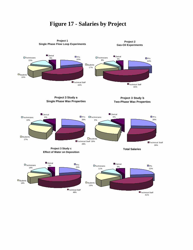
Figure 17 - Salaries by Project
Total Salaries
PI's23%
Technical Staff41%
Students19%
Technicians11%
Clerical6%
Project 1Single Phase Flow Loop Experiments
PI's20%
Students16%
Technicians15%
Clerical5%
Technical Staff44%
Project 2Gas-Oil Experiments
PI's24%
Technical Staff46%
Students17%
Technicians8%
Clerical5%
Project 3 Study aSingle Phase Wax Properties
PI's26%
Technical Staff28%
Students27%
Technicians10%
Clerical9%
Project 3 Study bTwo-Phase Wax Properties
PI's26%
Technical Staff26%
Students30%
Technicians
9%
Clerical9%
Project 3 Study cEffect of Water on Deposition
PI's21%
Technical Staff46%
Students14%
Technicians14%
Clerical5%

59
Appendix
LETTER OF AGREEMENT
PROJECT ORIENTED PARAFFIN DEPOSITION CONSORTIA
This Agreement, effective on this date of _________, is made and entered into by and between Company Name ("PARTICIPANT"), whose mailing address Company Address, and The University of Tulsa, a not for profit corporation having a principal place of business at 600 South College Ave, Tulsa, OK 74104-3187 hereinafter referred to as "UNIVERSITY". PARTICIPANTS will include oil and gas companies, service companies, and the Department of Energy (hereinafter "DOE"). UNIVERSITY is conducting research on “Paraffin Deposition Prediction in Multiphase Flowlines and Wellbores” (the "PROJECT"). PARTICIPANT desires to participate in the PROJECT and to have access to the results of the PROJECT from UNIVERSITY. Accordingly, in consideration of the mutual promises exchanged below, PARTICIPANT and UNIVERSITY hereby agree as follows: Article 1 - The PROJECT 1.1 UNIVERSITY will perform the PROJECT which will include, but not be limited to, the scope
of work defined in the attached Exhibit A. The PROJECT scope of work was developed under the assumption that many of the technical tasks are achievable in the time frame specified. Due to the research nature of the project, changes and rescheduling may be required. All changes in the scope of work, timetable and/or budget will require approval of the Project Advisory Board (delineated in Article 1.5).
1.2 The period of performance of the PROJECT under this Agreement is specified as a period of
three years from the commencement date unless sooner terminated in accordance with the provisions herein. The period of performance will automatically extend with the beginning of a new year. During the performance of the PROJECT, PARTICIPANT will be allowed to have input to the PROJECT, including monitoring the progress of the technical work, attending meetings with UNIVERSITY and UNIVERSITY'S engineering contractors and consultants, and providing comments and recommendations which will be given due regard and good faith consideration by UNIVERSITY with regard to the technical aspects of the PROJECT.
1.3 Two (2) copies of the final report (the “Report”) will be provided to PARTICIPANT at the
conclusion of each phase of the PROJECT. The Reports will contain a collection of deliverables for each PROJECT which are listed in Exhibit B.
1.4 The PROJECT will be performed by UNIVERSITY using mostly graduate students, research
associates and faculty, generally in accordance with the schedule contained in Exhibit C.
60
1.5 PARTICIPANTS will each appoint a Project Technical Representative to serve on the Project Advisory Board which will be established by UNIVERSITY for the PROJECT. The Project Advisory Board will provide input and make recommendations to UNIVERSITY to enhance the PROJECT; however, responsibility for direction and management of the PROJECT lies with UNIVERSITY.
1.6 The PROJECT is a non-profit cooperative industry-university-government research project in
which PARTICIPANTS can contribute funding in a lump-sum or over a period of three years. 1.7 UNIVERSITY will hold semi-annual Advisory Board Meetings. Article 2 - Grant 2.1 PARTICIPANT and Affiliates will have the non-exclusive, irrevocable world-wide royalty-free
rights to: (a) use the report and deliverables and all data and information contained therein in its
business; (b) make copies of the deliverables, and; (c) prepare derivative works based on the deliverables. PARTICIPANT may freely use, copy, distribute, and disclose the deliverables and all data
and information contained therein without restriction, and without accounting to UNIVERSITY or any other party therefore.
2.2 (a) Each PARTICIPANT will receive MODELS for predicting paraffin deposition in
multiphase flow (herein after MODEL) with Source Code and will have the right to transfer the MODEL with Source Code to third parties without accounting to UNIVERSITY or PARTICIPANTS.
(b) UNIVERSITY shall take all reasonable action to ensure that any software
developed or distributed pursuant to this agreement is free of all viruses. Article 3 - Commencement, Funding and Payment 3.1 Subject to Article 4.2 herein, the Commencement Date for the PROJECT shall be January
1, 2000. 3.2 The membership fee is $30,000 per year. PARTICIPANTS that were not members of the
PARAFFIN JIP will be charged an additional one time information fee of $35,000 which is waived for companies that agree to join for a minimum of three years.
(a) UNIVERSITY will invoice PARTICIPANTS on September 1 for the next PROJECT
Year. Payment is due within 30 days after the beginning of each PROJECT Year. 3.3 Unless PARTICIPANT agrees to an accelerated annual payment schedule, payment shall
be made according to the following schedule:
A PROJECT fee cost of $90,000 to PARTICIPANTS with two payment options shall be invoiced to each PARTICIPANT within thirty (30) days after execution of this Agreement to cover the total cost due from each PARTICIPANT. The two fee

61
schedules are listed in Exhibit D. UNIVERSITY will reference the title of this Agreement on each invoice and will mail the invoice to:
PARTICIPANT
Attn: Name
Address:
3.4 The payment from PARTICIPANT to UNIVERSITY determined according to Items 3.2 and
3.3 above, will be deemed to include sales, use, excise, or other similar tax which may be due as a result of the transfer of the results to PARTICIPANT or otherwise as a result of this Agreement. UNIVERSITY will separately list all such taxes on the invoice submitted to PARTICIPANT. As a not for profit corporation, UNIVERSITY is exempt from most taxes.
3.5 UNIVERSITY shall recruit and execute agreements similar to this Agreement with
additional PARTICIPANTS of the PROJECT. Fees resulting from such agreements may be used to provide funding, to replace the funding of a PARTICIPANT which has terminated its agreement or to enhance the PROJECT. All PARTICIPANTS shall have the same right to report, licenses and other PROJECT materials, except as otherwise provided for herein.
PARTICIPANT and each additional PARTICIPANT shall be provided with a list of all
PARTICIPANTS. 3.6 A PROJECT fee of $1,200,000 shall be invoiced to the National Petroleum Technology
Office (NPTO) to cover their costs according to EXHIBIT D. Article 4 - Termination 4.1 This Agreement may be terminated by either party under the following conditions: (a) PARTICIPANT may terminate this Agreement by giving UNIVERSITY at least sixty
(60) days advance written notice. In the event of such termination, PARTICIPANT agrees to forfeit its rights to receive any future reports on the progress of the PROJECT, licenses to computer programs and/or other copyrighted, patented or patentable materials produced by the PROJECT after the termination date, and the unspent portion of any funds invested in the PROJECT. In the event of such termination, PARTICIPANT shall have no further obligations to UNIVERSITY except to make any payments which may have become due under Article 3 above prior to termination.
(b) UNIVERSITY may terminate this Agreement by giving thirty (30) days written
notice to PARTICIPANT in the event that PARTICIPANT fails to make any payment in accordance with the schedule in Paragraph 3 above. PARTICIPANT agrees to forfeit its rights to PROJECT materials and licenses in accordance with Article 2 above, provided that within an additional sixty (60) day period PARTICIPANT may make such payment, in which case termination is not effected; provided, further, that no PARTICIPANT may delay payment by use of this provision more than once without advance written permission from UNIVERSITY and for good reason.
62
4.2 This Agreement is contingent upon UNIVERSITY obtaining DOE and participating
funding that adequately supports the PROJECT, as described in Exhibit E. Should this not occur, UNIVERSITY shall either terminate this Agreement and return all uncommitted funds to PARTICIPANTS after as provided for herein or seek approval within 30 days of all committed PARTICIPANTS to increase fee to cover costs.
Article 5 - Warranty and Liability 5.1 UNIVERSITY will not be liable to PARTICIPANT or any of its Affiliates for any damages to
any well, platform, drilling equipment, or other property, or for injury to any person as a result of any use by PARTICIPANT or its Affiliates of the data and information contained in the deliverables.
5.2 To the extent permitted by law, UNIVERSITY agrees to and hereby indemnifies and saves
PARTICIPANTS harmless from and against any and all claims of any kind, including but not limited to liability for injury to persons or damage to property, to the extent such claims arise from strict liability, negligent acts or omissions or intentional tortious conduct of UNIVERSITY, its employees, agents or assignees in the performance of the Work done under this Agreement including any and all expenses, costs, attorneys’ fees, settlements, judgments or awards incurred by PARTICIPANTS in the defense of any such claims or lawsuit.
5.3 UNIVERSITY represents that it is insured and that such insurance and other insurance that
may be carried by UNIVERSITY shall be sufficient for any and all liabilities and risks associated with the proposed Work and shall cover all UNIVERSITY’S operations during the performance of this Agreement.
UNIVERSITY shall not allow any subcontractor to commence any part of the Work until it
shall obtain and maintain for the period of performance of the subcontract, Worker’s Compensation and/or all other necessary social insurance and Comprehensive General Liability insurance, and if applicable, Professional Liability Insurance, covering all the subcontractor’s operations under this Contract, in the minimum amount of Two Million Dollars ($2,000,000.00).
All policies of insurance obtained pursuant to this Agreement shall provide that such
insurance shall not be changed or canceled until thirty (30) days prior written notice has been given to PARTICIPANTS.
Article 6 - Miscellaneous 6.1 UNIVERSITY will not use the name of PARTICIPANT in any advertising or publication
relating to the subject matter of this Agreement without PARTICIPANT'S prior written consent.
6.2 The validity and interpretation of this Agreement will be governed by the laws of the state of
Oklahoma. The parties agree that venue is proper in a court of competent jurisdiction in Tulsa County, Oklahoma.
6.3 The term “Affiliate” as used herein with respect to PARTICIPANT will mean and include
PARTICIPANT and any other company at least fifty percent (50%) of whose stock having the right to vote for or appoint is now or hereafter owned or controlled, directly or indirectly, by PARTICIPANT or any other company which owns or controls directly or indirectly at least fifty percent (50%) of the stock of PARTICIPANT.
63
6.4 This Agreement sets forth the entire understanding between the parties, and supersedes,
cancels, and merges all prior representations, understandings, covenants, or agreements, whether oral or written, with respect to the subject matter hereof. No change, alteration, or modification to this Agreement will be effective unless it is in writing and signed by the authorized representative of both parties.
6.5 In the event of any conflict between the foregoing terms and conditions and attached
Exhibits A, B, C, D, and E the foregoing terms and conditions will be deemed to be controlling.
6.6 The parties will attempt in good faith to resolve any controversy or claim arising out of or
relating to this Agreement by mediation in accordance with the Center for Public Resources MODEL Procedure for Mediation of Business Disputes and as such procedural document may be amended from time to time.
6.7 The following legal notice shall be affixed to each technical report, and at a minimum on the
diskette label, on the first screen of any such Computer Program and on any copies of the Source Code furnished or disseminated by UNIVERSITY to PARTICIPANTS hereunder and to any report resulting from this agreement:
LEGAL NOTICE
This report was prepared by (‘UNIVERSITY’) as an account of work sponsored by the U.S.
Department of Energy (DOE) and PARTICIPANTS. Neither UNIVERSITY, DOE, PARTICIPANTS, their Affiliates, members, nor any person acting on behalf of either:
(a) Makes any warranty or representation, express or implied with respect to the
accuracy, completeness, or usefulness of the information contained in this program or report, or that the use of any information, apparatus, method or process disclosed in this report may not infringe privately-owned rights, or
(b) Assumes any liability with respect to the use of, or for any and all damages
resulting from the use of, any information, apparatus, method or process disclosed in this report.
6.8 The parties agree that rights or obligations under this Agreement may not be assigned by
PARTICIPANT without prior written consent from UNIVERSITY. 6.9 The parties separately represent that they comply to the extent applicable with all
applicable federal and state laws prohibiting discrimination against any member of a class protected against discrimination under such laws. Each party further represents and warrants that it is in compliance with the Americans with Disabilities Act to the extent applicable.
6.10 The parties agree that UNIVERSITY shall hold title to all patents, copyrights and
trademarks resulting from this Agreement. A royalty-free, non-exclusive, worldwide, irrevocable patent license will be granted by UNIVERSITY to PARTICIPANTS, their subsidiaries and affiliates, including the right to make, use and sell inventions covered by such patents.
6.11 The failure of either party to exercise its rights arising from a breach of this Agreement shall
not be deemed a waiver of such rights.
64
Article 7 – Assurances of Compliance
7.1 UNIVERSITY will keep accurate books, records, and other documentation in accordance with generally accepted accounting practice to support all charges made hereunder and to verify that any fees received pursuant to Article 3 have been properly handled. For two years following completion of the PROJECT, University will preserve such books, records, and other documentation and will permit representatives of PARTICIPANT to inspect them during usual business hours and to make excerpts therefrom for the purpose of auditing and verifying such charges and fee handling.
7.2 UNIVERSITY shall establish and maintain such business standards, procedures, and controls as
are necessary to avoid any real or apparently impropriety in connect6ion with the Project or any adverse impact on the interests of PARTICIPANT or any of its affiliates. At the request of PARTICIPANT, University shall review with limitation those related to the activities of University’s employees and agents with their relations with PARTICIPANT’S employees, agents, and representatives, and with third parties.
7.3 While performing the PROJECT, University’s employees, agents, and subcontractors will not be
under the influence of alcohol, any unprescribed controlled substances, or any misused legitimate prescription drugs. University shall ensure that all of its employees, agents, and subcontractors who may be asked to perform services under the Project are aware of and will comply with the provisions of this Paragraph.
7.4 If the UNIVERSITY does subcontract any portion of the PROJECT, UNIVERSITY will enter into a
written subcontract with each subcontractor. Each subcontractor will secure for PARTICIPANTS rights to the results of the subcontracted work which are at least equivalent to those set forth in Article 2 of this Agreement.
In consideration of the foregoing terms and conditions, PARTICIPANT and UNIVERSITY have executed this agreement in duplicate originals which shall be of equal dignity and are to be effective the date first written above.
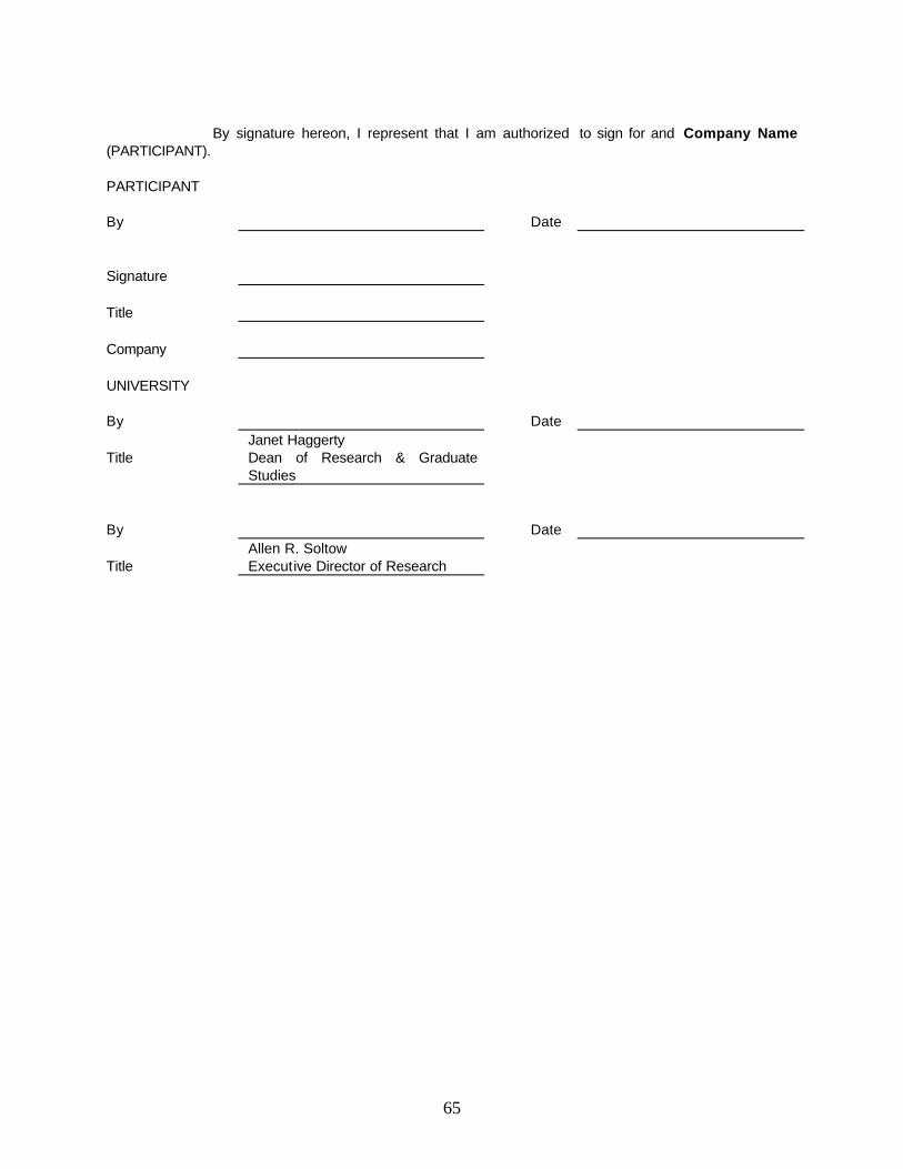
65
By signature hereon, I represent that I am authorized to sign for and Company Name (PARTICIPANT). PARTICIPANT
By Date Signature Title Company UNIVERSITY
By Date Janet Haggerty Title Dean of Research & Graduate
Studies By Date Allen R. Soltow Title Executive Director of Research

66

67
LETTER OF AGREEMENT
Exhibit A
PROPOSED SCOPE OF WORK
Two state-of-the-art test facilities, P&ID shown in Figure 12, were developed for use in the current JIP. These facilities were used to generate high-quality data. It is proposed that these facilities be utilized to gather large quantities of single and multiphase flow data to enhance the capabilities of the predictive models during the first three years of the Project Oriented Paraffin Deposition Consortium. The work plan for this Project Oriented Paraffin Deposition Consortium shows the project beginning with three projects (Project 1 – conduct a large number of single-phase flow tests to more accurately model the single-phase deposition process; Project 2 – conduct a large number of two-phase flow tests to more accurately model the two-phase deposition process and Project 3 – focused experiments that would shed light on various aspects of deposition physics and the effect of water). The task schedules for Projects 1-3 are described below.
Project 1: Additional Single-Phase Oil Tests
In general, the effects of oil temperature and the difference between the oil and coolant temperatures on deposition rate can be predicted with a molecular diffusion model. However, no deposition model exists that can account for the effects of flow rate and aging, and predict trapped oil content and thermal conductivity of deposits. It is clear from the experiments conducted in the current Paraffin JIP that neither shear dispersion nor molecular diffusion can adequately predict all the paraffin deposition phenomena that were observed. More basic research is needed, as is a larger, more diverse database. The first project conducted in the new consortium will include tasks that must be completed to gain a better understanding of paraffin deposition in single-phase flow. An MS student and a visiting Scholar sponsored by Elf will conduct the flow loop experiments. The tasks for this project include automating the single-phase flow loop, conducting additional single-phase paraffin deposition tests, and enhancing the existing single-phase model to be less dependent on a specific oil. Each of these tasks is discussed in greater detail below.
Test Facility Enhancement While conducting the single-phase flow tests, a number of recommendations were made that would improve the flow loop, thereby enabling the operator to take higher quality single-phase data. Objective: Modify the single-phase flow loop to enable obtaining higher quality data.
The modifications to the existing single-phase flow loop will take five months. A static mixer will be added to eliminate the non-uniform temperature distributions observed during laminar testing. Existing manual valves will be replaced with computer controlled valves. The data acquisition system will be changed to Intellution Fix 32 Control software that will enable the tests to be automated and also permit simultaneous analysis of data. Temperature sensitive components in the instrument patch panel will be replaced and the pressure tap lines in the test section will be heat traced.
Single-Phase Paraffin Deposition Tests Objective: Use the flow loop to obtain single-phase test data on three oils: the South Pelto black oil, the Garden Banks
condensate and a black oil from the Rocky Mountain Oil Technology Center (RMOTC) that is currently planned for use in a DeepStar study.
68
The single-phase flow tests will generate new data for making improvements to the existing single-phase paraffin deposition model. They will also provide a better understanding of flow regime dependence, the effect of lower temperature gradients on paraffin crystal properties, and provide insight into deposit aging (much longer running times), shear stripping, mechanical strength, roughness and trapped oil concentration.
Use of the RMOTC crude oil depends on whether this oil is indeed used in future tests planned by
both Texaco (4-in. flow loop) and DeepStar (possible 6-in. flow loop). These data would provide valuable scale-up information when compared with data from TU (1.7-in. flow loop).
Single-Phase Model Enhancements Objective: Modify the current single-phase model to minimize the dependency on a single crude oil.
After the single-phase flow paraffin deposition model enhancements are made, the computer program will be turned over to a software company, such as MSI, to enhance the user-friendly graphical user interface.
Project 2: Additional Gas-Oil Tests
Tests have been conducted using South Pelto crude oil and natural gas at a pressure of 350 psia (24 bars). Ten tests have been conducted with the loop in a horizontal configuration (0o), six in a vertical configuration (90o) and three uphill and three downhill tests (+2o and –1o). The test conditions included one inlet two-phase mixture temperature and one inlet coolant temperature. Additional gas-oil test data are needed to adequately model paraffin deposition in two-phase flow.
The second project conducted in the new consortium will include tasks that must be completed to
gain a more in-depth understanding of paraffin deposition in two-phase flow. A Ph.D. student and a Post Doctoral Research Associate will conduct this project. The tasks for this project include upgrading the flow loop, development of a mechanistic heat transfer model, conducting numerous additional two-phase paraffin deposition tests, and enhancing the existing two-phase model developed in the current Paraffin JIP.
Test Facility Upgrade Objective: Modify the two-phase flow loop to enable obtaining higher quality data as well as permit long (days) term
testing.
The modifications to the existing two-phase flow loop will take three months. Piping modifications will be made that will allow for feed gas injection at a constant flow rate throughout the duration of a test in order to maintain a constant system pressure. Piping changes will also be made that will allow gas that accumulates in the oil tank to be transferred to the receiver, thereby allowing the oil in the separator to be at a relatively constant level during a long duration test. A LabView™ based data acquisition system will be added to supplement the existing data acquisition system. This will allow fast data acquisition rates for the gamma densitometer and selected other signals.
Mechanistic Heat Transfer Model Development Objective: Conduct heat transfer studies and develop flow pattern dependent mechanistic heat transfer model.
The model that is developed will be transformed into a computer code. The model predictions will be compared to the experimental data gathered. If necessary, the model will be refined and/or enhanced. The final model will be integrated into the existing two-phase deposition computer program.
69
Two-Phase Paraffin Deposition Tests Objective: Use the test facility to obtain additional two-phase deposition data using the South Pelto crude oil.
The two-phase flow tests will generate additional deposition data with the test section in the horizontal, vertical and limited inclined positions. The two-phase flow tests will generate additional data for making improvements to the existing two-phase paraffin deposition model. They will also provide a better understanding of flow pattern dependence, flow regime (laminar vs. turbulent) dependence, the effect of lower temperature gradients on paraffin crystal properties, and provide insight into deposit aging (much longer running times), shear stripping, roughness and trapped oil concentration.
Two-Phase Model Enhancements Objective: Modify the current two-phase model to more accurately predict paraffin deposition in a two-phase flow
environment.
After the two-phase flow paraffin deposition model enhancements are made, the computer program will be turned over to a software company, such as MSI, to enhance the user-friendly graphical user interface.
Project 3 - Deposition Physics and Water Impact Studies
Objective: Conduct focused experiments to better understand various aspects of deposition physics and the effect of water on deposition.
Previous single-phase flow studies have identified issues such as how the composition of the deposit changes with time or what the shear mechanics are along the pipe wall. By isolating phenomena such as these, an understanding of the deposition physics will be gained. The term deposition physics is used to denote the many phenomena beyond molecular diffusion that influence paraffin deposition. Other issues such as the impact on the deposition rate from adding water are not well understood. The findings from studies such as these will be incorporated into the model for predicting paraffin deposition. Specific studies within Project 3 are listed below; however, discussions will be held with the participants and the scope of the studies will be finalized before they are commenced.
Study a: Single-Phase Paraffin Properties
Spool Piece Modification Objective: Modify both single-phase spool pieces to allow taking samples as a function of time.
Design, development and testing will take seven months. It is envisioned that a retractable coupon sampler will be installed. A prototype system will be developed and tested. Necessary modifications will be made and two spool pieces will be built.
Single-Phase Paraffin Property Determination Objective: Use the coupon sampler to determine physical properties of paraffin samples as a function of time.
The coupon sampler will provide samples that once analyzed will provide insight into the aging process and the mechanical strength of the paraffin deposit as a function of time. The results from these measurements will be used to make improvements to the existing single-phase model.
70
Single-Phase Model Enhancements Objective: Modify the current single-phase model to more accurately account for aging and shear strength of paraffin
deposits.
After the single-phase flow paraffin deposition model enhancements are made, the computer program will be turned over to a software company, such as MSI, to enhance the user-friendly graphical user interface.
Study b: Two-Phase Paraffin Properties
Objective: Analyze paraffin deposits after conducting long term tests (one week to one month in duration) to better understand the aging process as well as the layering effect observed in field deposits.
This study will investigate the aging process in two-phase flow by conducting deposition tests that are run for 5 days. The deposits will be analyzed for occluded oil. Some long-term tests (30 days) will be run to examine the layering effect observed in field samples and long term aging. Samples will be taken from each layer and analyzed for occluded oil, density, composition, shear strength, etc.
Two-Phase Model Enhancements Objective: Modify the two-phase model to more accurately account for aging and the prediction of long term deposition.
After the two-phase flow paraffin deposition model enhancements are made, the computer program will be turned over to a software company, such as MSI, to enhance the user-friendly graphical interface.
Study c: Effects of Water on Paraffin Deposition
The third study in Project 3 will investigate the effects of water on paraffin deposition under multiphase flow conditions. This study will be conducted by an MS student and a Post Doctoral Research Associate. The tasks for this study include expanding the gas-oil deposition flow loop to handle a third phase (water), and conducting two and three-phase paraffin deposition tests. Each of these tasks is discussed in greater detail below.
Flow Loop Expansion Objective: Modify the two-phase flow loop to accommodate water
Expansion of the two-phase flow loop will take five months. A second Moyno pump will be added and a water-oil separation facility will be designed and installed. Automated valves will be purchased and the piping and associated instrumentation installed. The entire water facility will be insulated.
Two and Three-Phase Paraffin Deposition Tests Objective: Conduct a sufficient number of two-phase (oil-water) and three-phase (gas-oil-water) tests using the South Pelto
crude oil to provide an understanding of the impact water has on paraffin deposition in a multiphase flow environment.
The oil-water and gas-oil-water tests will be conducted with the flow loop in a horizontal position. At least two water cuts will be used. These multiphase flow tests will generate unique data that will be utilized in developing a preliminary understanding of the deposition process when water is present in flowlines and wellbores. These tests will also provide some insight on shear stripping, roughness and occluded oil concentration in paraffin. The need to conduct more extensive tests in a follow-on investigation will be evaluated.
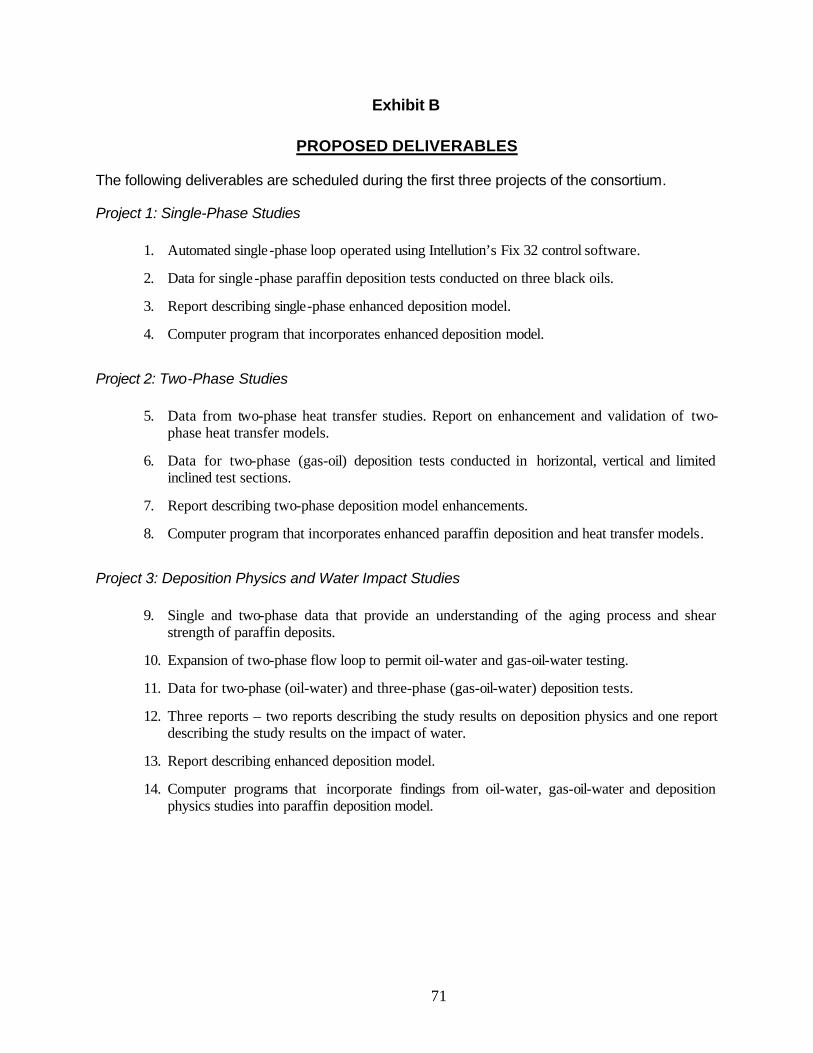
71
Exhibit B
PROPOSED DELIVERABLES
The following deliverables are scheduled during the first three projects of the consortium.
Project 1: Single-Phase Studies
1. Automated single-phase loop operated using Intellution’s Fix 32 control software.
2. Data for single-phase paraffin deposition tests conducted on three black oils.
3. Report describing single-phase enhanced deposition model.
4. Computer program that incorporates enhanced deposition model.
Project 2: Two-Phase Studies
5. Data from two-phase heat transfer studies. Report on enhancement and validation of two-phase heat transfer models.
6. Data for two-phase (gas-oil) deposition tests conducted in horizontal, vertical and limited inclined test sections.
7. Report describing two-phase deposition model enhancements.
8. Computer program that incorporates enhanced paraffin deposition and heat transfer models.
Project 3: Deposition Physics and Water Impact Studies
9. Single and two-phase data that provide an understanding of the aging process and shear strength of paraffin deposits.
10. Expansion of two-phase flow loop to permit oil-water and gas-oil-water testing.
11. Data for two-phase (oil-water) and three-phase (gas-oil-water) deposition tests.
12. Three reports – two reports describing the study results on deposition physics and one report describing the study results on the impact of water.
13. Report describing enhanced deposition model.
14. Computer programs that incorporate findings from oil-water, gas-oil-water and deposition physics studies into paraffin deposition model.

72
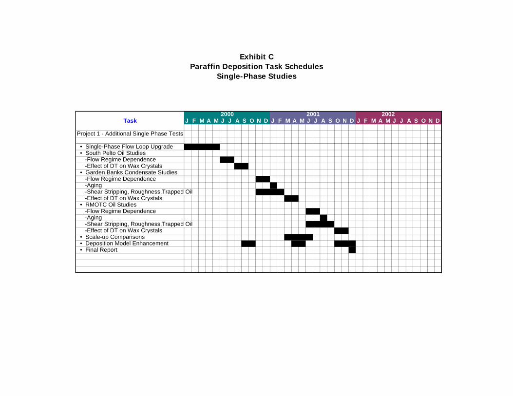
Exhibit CParaffin Deposition Task Schedules
Single-Phase Studies
Task J F M A M J J A S O N D J F M A M J J A S O N D J F M A M J J A S O N D
Project 1 - Additional Single Phase Tests
• Single-Phase Flow Loop Upgrade • South Pelto Oil Studies -Flow Regime Dependence -Effect of DT on Wax Crystals • Garden Banks Condensate Studies -Flow Regime Dependence -Aging -Shear Stripping, Roughness,Trapped Oil -Effect of DT on Wax Crystals • RMOTC Oil Studies -Flow Regime Dependence -Aging -Shear Stripping, Roughness,Trapped Oil -Effect of DT on Wax Crystals • Scale-up Comparisons • Deposition Model Enhancement • Final Report
2000 2001 2002

Exhibit CParaffin Deposition Task Schedules
Gas-Oil Studies
Task J F M A M J J A S O N D J F M A M J J A S O N D J F M A M J J A S O N D
Project 2- Additional S. Pelto Gas-Oil Tests
• Two-Phase Flow Loop Upgrade • Heat Transfer Studies • Mechanistic Model Development • S. Pelto Gas-Oil Tests (Horizontal) -Determine Flow Pattern Dependence -Aging -Shear Stripping, Roughness,Trapped Oil • S. Pelto Gas-Oil Tests (Vertical) -Determine Flow Pattern Dependence X X X -Aging X X -Shear Stripping, Roughness,Trapped Oil X X X X X X • S. Pelto Gas-Oil Tests (Inclined) -Determine Flow Pattern Dependence X X X -Aging X X -Shear Stripping, Roughness,Trapped Oil X X X X X X • Deposition Model Enhancement X X X X X X • Two-Phase Model Enhancement X X X X X X x x
2000 2001 2002
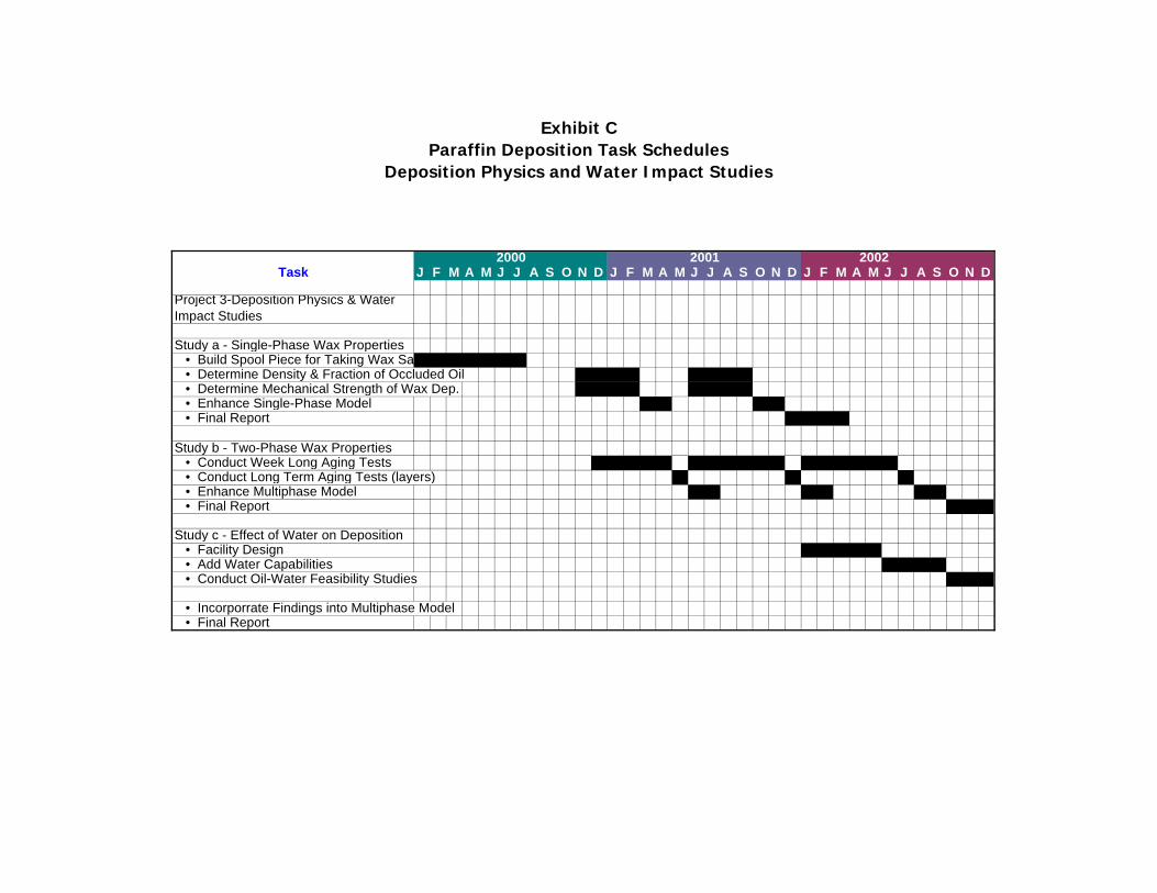
Exhibit CParaffin Deposition Task Schedules
Deposition Physics and Water Impact Studies
Task J F M A M J J A S O N D J F M A M J J A S O N D J F M A M J J A S O N D
Project 3-Deposition Physics & Water Impact Studies
Study a - Single-Phase Wax Properties • Build Spool Piece for Taking Wax Samples • Determine Density & Fraction of Occluded Oil • Determine Mechanical Strength of Wax Dep. • Enhance Single-Phase Model • Final Report
Study b - Two-Phase Wax Properties • Conduct Week Long Aging Tests • Conduct Long Term Aging Tests (layers) • Enhance Multiphase Model • Final Report
Study c - Effect of Water on Deposition • Facility Design • Add Water Capabilities • Conduct Oil-Water Feasibility Studies • Incorporrate Findings into Multiphase Model • Final Report
2000 2001 2002
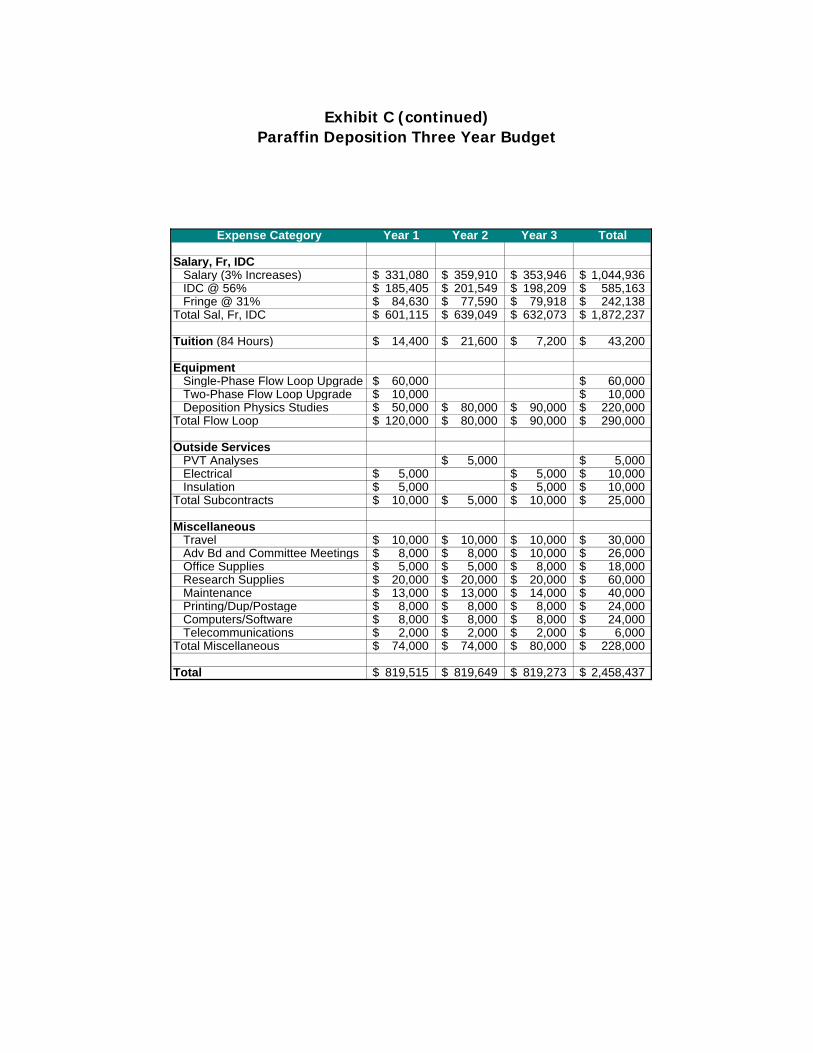
Exhibit C (continued)Paraffin Deposition Three Year Budget
Expense Category Year 1 Year 2 Year 3 Total
Salary, Fr, IDC Salary (3% Increases) 331,080$ 359,910$ 353,946$ 1,044,936$ IDC @ 56% 185,405$ 201,549$ 198,209$ 585,163$ Fringe @ 31% 84,630$ 77,590$ 79,918$ 242,138$ Total Sal, Fr, IDC 601,115$ 639,049$ 632,073$ 1,872,237$
Tuition (84 Hours) 14,400$ 21,600$ 7,200$ 43,200$
Equipment Single-Phase Flow Loop Upgrade 60,000$ 60,000$ Two-Phase Flow Loop Upgrade 10,000$ 10,000$ Deposition Physics Studies 50,000$ 80,000$ 90,000$ 220,000$ Total Flow Loop 120,000$ 80,000$ 90,000$ 290,000$ Outside Services PVT Analyses 5,000$ 5,000$ Electrical 5,000$ 5,000$ 10,000$ Insulation 5,000$ 5,000$ 10,000$ Total Subcontracts 10,000$ 5,000$ 10,000$ 25,000$
Miscellaneous Travel 10,000$ 10,000$ 10,000$ 30,000$ Adv Bd and Committee Meetings 8,000$ 8,000$ 10,000$ 26,000$ Office Supplies 5,000$ 5,000$ 8,000$ 18,000$ Research Supplies 20,000$ 20,000$ 20,000$ 60,000$ Maintenance 13,000$ 13,000$ 14,000$ 40,000$ Printing/Dup/Postage 8,000$ 8,000$ 8,000$ 24,000$ Computers/Software 8,000$ 8,000$ 8,000$ 24,000$ Telecommunications 2,000$ 2,000$ 2,000$ 6,000$ Total Miscellaneous 74,000$ 74,000$ 80,000$ 228,000$
Total 819,515$ 819,649$ 819,273$ 2,458,437$

Exhibit DProposed Fee Schedule
Fiscal Participants Participants DOEYear Option A Option B
2000 30,000.00$ 81,000.00$ 400,000.00$ 2001 30,000.00$ 400,000.00$ 2002 30,000.00$ 400,000.00$
Total 90,000.00$ 81,000.00$ 1,200,000.00$
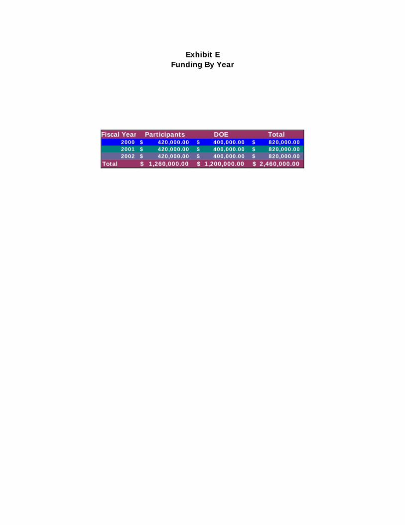
Exhibit EFunding By Year
Fiscal Year Participants DOE Total2000 420,000.00$ 400,000.00$ 820,000.00$ 2001 420,000.00$ 400,000.00$ 820,000.00$ 2002 420,000.00$ 400,000.00$ 820,000.00$
Total 1,260,000.00$ 1,200,000.00$ 2,460,000.00$