Embed Size (px)
Citation preview

PROPORTIONAL-INTEGRAL-DERIVATIVE CONTROL ALGORITHM WITH
DELAY COMPENSATION FOR STEER-BY-WIRE UNDER
NETWORK CONTROLLED SYSTEM
MOHD SAZLAN BIN ZAINAL
A project report submitted in partial fulfilment of the
requirements for the award of the degree of
Master of Engineering (Mechatronics & Automatic Control)
Faculty of Electrical Engineering
Universiti Teknologi Malaysia
DECEMBER 2015

iii
To my parents, who has been supportive throughout my life, my wife and children,
for their love, support, patience, sacrifice and encouragements.
iv
ACKNOWLEDGEMENT
Alhamdullilah. First and foremost, my grateful appreciation goes to Allah s.w.t
for His blessing and lending me the strength in the process of completing this project.
In this opportunity, I would like to express my gratitude to my supervisor,
Associate Professor Dr. Abdul Rashid bin Husain for the guidance, encouragement,
critics, advice and a lot of brilliant ideas. Without his continued support and interest,
this thesis would not have been the same as presented here.
I am indebted to the Ministry of Higher Education for funding my studies here
in Universiti Teknologi Malaysia.
My sincere appreciation also goes to my fellow postgraduate students for their
support, knowledge sharing and assistance at various occasion during my postgraduate
experience. Unfortunately, it is not possible to list all of them in this limited space but
their friendly faces and gestures will always be remembered.
Last but not least, my special warmest gratitude goes to my parent and family,
whom are very supportive to me during the period of my study. Special thanks to my
wife, Marjan Mastura binti Mohamad and my three cheeky but kind and adorable
children, Muhammad Sofiy, Marissa Sofia and Munira Sofia for being patient and so
understanding to me. Their love, sacrifice and support will always be there in a special
place in my heart. Thank you.
v
ABSTRACT
Controller Area Network (CAN) is a popular network commonly used in the
automotive industry which is an advanced serial bus system designed for real-time
control system. This thesis addresses the modelling and controller design for Steer-by-
Wire (SbW) system under the influence of a network controlled system. The analysis
of the control performance of the SbW system under several CAN configuration
setting is discussed in detail. The mathematical model of the SbW system is adopted
from previous research works using both steering rack dynamic and the vehicle system
dynamic. Proportional-Integral-Derivative (PID) controller that can compensate delay
is designed to achieve the desired control performance of the SbW system. The
analysis of the control performance is solely based on the simulation conducted in the
Matlab/Simulink software environment with Truetime toolbox to simulate the real
time performance of the SbW system. The simulation is performed based on nine
different cases in the event of several difference in the CAN network properties such
as the network speed, sampling periods, scheduling techniques, rate of data losses,
interruption by higher priority data and clock drift to evaluate the control performance
of the SbW system. The result is found that the SbW system control performance
deteriorates by the selection of low network speed, sensor’s sampling periods and the
rate of data losses.

vi
ABSTRAK
Pengawal Rangkaian Kawasan (CAN) adalah rangkaian popular yang biasa
digunakan dalam industri automotif iaitu sistem talian rangkaian bersiri canggih yang
direka untuk sistem kawalan masa nyata. Laporan tesis ini melaporkan kaedah untuk
mendapatkan model dan merekabentuk pengawal untuk sistem Pacuan-melalui-Wayar
(SbW) dibawah pengaruh sistem kawalan rangkaian. Analisis prestasi kawalan sistem
SbW di bawah beberapa tetapan konfigurasi CAN dibincangkan secara menyeluruh
dan terperinci. Model matematik sistem SbW yang diguna pakai dari kajian sebelum
ini, menggunakan kedua-dua model dinamik rak roda stereng dan model dinamik
sistem kenderaan. Pengawal Berkadar-Kamiran-Terbitan (PID) yang boleh
menyelesaikan masalah lengah masa direka untuk mencapai prestasi kawalan yang
dikehendaki oleh sistem SbW itu. Analisis prestasi kawalan adalah berasaskan kepada
simulasi yang dijalankan menggunakan perisian Matlab/Simulink dengan Truetime
untuk mensimulasikan prestasi masa nyata sistem SbW itu. Simulasi ini dijalankan
berdasarkan sembilan kes yang berbeza mengikut beberapa perbezaan dalam ciri-ciri
rangkaian CAN seperti kelajuan rangkaian, tempoh persampelan, teknik penjadualan,
kadar kehilangan data, gangguan oleh data yang lebih utama dan gelinciran waktu
untuk menilai prestasi kawalan sistem SbW. Hasilnya didapati bahawa prestasi sistem
kawalan SbW merosot dengan pemilihan kelajuan rangkaian yang rendah, tempoh
persampelan di pengesan dan kadar kehilangan data.

vii
TABLE OF CONTENTS
CHAPTER TITLE PAGE
DECLARATION ii
DEDICATION iii
ACKNOWLEDGEMENTS iv
ABSTRACT v
ABSTRAK vi
TABLE OF CONTENTS vii
LIST OF TABLES x
LIST OF FIGURES xi
LIST OF SYMBOLS xiii
LIST OF ABBREVIATIONS xv
LIST OF APPENDICES xvii
1 INTRODUCTION 1
1.1 Introduction 1
1.1.1 Conventional Steering System 2
1.1.2 Steer-by-Wire (SbW) System 4
1.1.2.1 Steer-by-Wire (SbW) System
Requirements
6
1.2 Problem Statement 7
1.3 Objectives of the Project 7
1.4 Scopes of the Project 8
1.5 Outline of Thesis 9

viii
2 LITERATURE REVIEW 10
2.1 Modelling of Steer-by-Wire (SbW) System 11
2.2 Control Methods and Strategies 13
2.3 Steer-by-Wire (SbW) in Networked Controlled
System (NCS)
17
2.4 Proportional-Integral-Derivative (PID) with
Delay Compensation
19
2.5 Components of Delay in Network Controlled
System (NCS)
21
2.6 Conclusion of the Literature Review 23
3 METHODOLOGY 24
3.1 Steer-by-Wire (SbW) System Model 27
3.1.1 Dynamic Model of a Steering Rack at
Front Wheel Side
28
3.1.2 Vehicle Dynamics Model 30
3.2 PID Controller 33
3.2.1 Practical Aspect of the PID Controller 35
3.3 Conclusion of the Methodology 37
4 SIMULATION RESULT AND DISCUSSION 38
4.1 Simulation Environment Setup 39
4.1.1 Block Diagram Setup of the Steer-by-
Wire (SbW) System
39
4.1.2 Controller Area Network (CAN) 42
4.1.3 Matlab/Truetime Simulation Toolbox 44
4.2 Simulation Parameters 46
4.2.1 Steer-by-Wire (SbW) System Parameters 46
4.2.2 Controller Area Network (CAN)
Simulation Parameters
48
4.2.3 Proportional-Integral-Derivative (PID)
Controller Parameters
50
4.2.4 System Performance Indices 51
4.3 Simulation Result and Discussion for Nine
Different Cases of Steer-by Wire System (SbW)
52
ix
4.3.1 Case 1: SbW System without CAN
network
52
4.3.2 Case 2: SbW System in Ideal CAN
Network
54
4.3.3 Case 3: SbW System in High Speed CAN
Network
57
4.3.4 Case 4: SbW System in Low Speed CAN
Network
60
4.3.5 Case 5: A Change in Sensor’s Sampling
Time in CAN Network
62
4.3.6 Case 6: Interruption by Higher Priority
Nodes in CAN Network
64
4.3.7 Case 7: Network Data Losses in CAN
Network
67
4.3.8 Case 8: Scheduling Technique in CAN
Network
70
4.3.9 Case 9: Clock Drift Phenomenon in
CAN Network
73
4.4 SbW System Control Performance 76
4.5 Summary of the Simulation Result and
Discussion
77
5 CONCLUSION AND RECOMMENDATION FOR
FUTURE WORKS
79
5.1 Conclusion 79
5.2 Recommendation for Future Works 81
REFERENCES 82
Appendices A – J 89 - 98

x
LIST OF TABLES
TABLE NO. TITLE PAGE
4.1 Steer-by-Wire (SbW) System Parameters 47
4.2 Nodes Configuration of Controller Area Network
(CAN) for Steer-By-Wire (SbW) System Simulation
49
4.3 PID Tuned Parameters 50
4.4 CAN Network Configuration Parameters for Case 2 54
4.5 CAN Network Configuration Parameters for Case 3 57
4.6 CAN Network Configuration Parameters for Case 4 60
4.7 CAN Network Configuration Parameters for Case 5 62
4.8 CAN Network Configuration Parameters for Case 6 64
4.9 CAN Network Configuration Parameters for Case 7 67
4.10 CAN Network Configuration Parameters for Case 8 70
4.11 CAN Network Configuration Parameters for Case 9 73
4.12 Performance Comparison of the SbW System for
Each Cases in CAN Network
76
xi
LIST OF FIGURES
FIGURE NO. TITLE PAGE
1.1 Parallelogram Linkage Steering System 3
1.2 Rack and Pinion Steering System 4
1.3 Comparison of Conventional Steering System and SbW
System
5
2.1 Components of Delay in Time-Driven Systems 22
3.1 Flowchart of the Project Methodology 24
3.2 Full Project Methodology 26
3.3 Overview of SbW System 27
3.4 Steering Rack at Front Wheel Dynamic 28
3.5 Single Track Vehicle Model 30
4.1 Overall SbW System Block Diagram without CAN
Network
39
4.2 Overall SbW System Block Diagram with CAN
Network
40
4.3 SbW Simulation Block Diagram without CAN Network 41
4.4 SbW Simulation Block Diagram with CAN Network 41
4.5 Node A Wins Arbitration over Node B 43
4.6 Truetime Matlab/Simulink Block Diagram 45
4.7 Response of SbW System without CAN Network 52
4.8 Voltage of DC Motor of SbW System without CAN
Network
53
4.9 Road Wheel Angle, 𝜃𝑟 vs Steering Wheel Angle, 𝜃𝑠 for
Case 2
55
xii
4.10 Voltage of DC Motor of SbW System in Case 2 56
4.11 Road Wheel Angle, 𝜃𝑟 vs Steering Wheel Angle, 𝜃𝑠 for
Case 3
58
4.12 Voltage of DC Motor of SbW System in Case 3 59
4.13 Road Wheel Angle, 𝜃𝑟 vs Steering Wheel Angle, 𝜃𝑠 for
Case 4
61
4.14 Voltage of DC Motor of SbW System in Case 4 61
4.15 Road Wheel Angle, 𝜃𝑟 vs Steering Wheel Angle, 𝜃𝑠 for
Case 5
63
4.16 Voltage of DC Motor of SbW System in Case 5 63
4.17 Road Wheel Angle, 𝜃𝑟 vs Steering Wheel Angle, 𝜃𝑠 for
Case 6
65
4.18 Voltage of DC Motor of SbW System in Case 6 66
4.19 Road Wheel Angle, 𝜃𝑟 vs Steering Wheel Angle, 𝜃𝑠 for
Case 7
68
4.20 Voltage of DC Motor of SbW System in Case 7 69
4.21 Road Wheel Angle, 𝜃𝑟 vs Steering Wheel Angle, 𝜃𝑠 for
Case 8
71
4.22 Voltage of DC Motor of SbW System in Case 8 72
4.23 Road Wheel Angle, 𝜃𝑟 vs Steering Wheel Angle, 𝜃𝑠 for
Case 9
74
4.24 Voltage of DC Motor of SbW System in Case 9 75

xiii
LIST OF SYMBOLS
𝜏𝑝 - Processing Delay
𝜏𝑛 - Network Delay
𝜏𝑠 - Synchronization Delay
𝜏𝑐𝑙 - Closed-Loop Delay
𝜏𝑠𝑐 - Delay from Sensor to Controller
𝜏𝑐𝑎 - Delay from Controller to Actuator
�̈�𝑟 - Road Wheel Angular Acceleration
𝑏𝑟 - Viscous Damping Coefficient
𝐽𝑟 - Moment Of Inertia of The Road Wheel
�̇�𝑟 - Road Wheel Angular Velocity
𝜂 - Steering Ratio
𝐾𝑡𝑟 - Constant
𝑖𝑟 - Motor Current
𝜏𝑎 - Self-Aligning Torque
𝜏𝑓 - Friction Torque
𝑖̇̇𝑟 - Derivative of Motor Current
𝐾𝑒𝑟 - Constant
𝐿𝑟 - Motor Inductance
𝑅𝑟 - Motor Resistance
𝑉𝑟 - Motor Voltage
𝐶𝛼𝐹 - Front Tire Cornering Coefficient
𝛼𝐹 - Front Tire Slip Angle
𝑔 - Gravity Acceleration
𝑡𝑝 - Tire Pneumatic Trail

xiv
𝑡𝑚 - Tire Mechanical Trail
𝑊𝑓 - Front Tire Weight
𝜇 - Friction Coefficient
𝛽 - Vehicle Body Slip Angle
𝑟 - Yaw Rate
𝑎 - Distance from the Front Tire to the Vehicle Centre of
Gravity
𝑏 - Distance from the Rear Tire to the Vehicle Centre of
Gravity
𝑣 - Vehicle Longitudinal Velocity
𝐶𝛼𝑅 - Rear Tire Cornering Coefficient
𝑚 - Vehicle Mass
𝐼𝑧 - Vehicle Moment of Inertia
𝜃𝐿 - Left Steering Angles
𝜃𝑅 - Right Steering Angles
𝛼𝑅 - Rear Tire Slip Angle
𝑢 - Control Signal
𝐾𝑝 - Proportional Gain
𝑒 - Error Signal
𝑇𝑖 - Integral Time Constant
𝑇𝑑 - Derivative Time Constant
𝑢𝑝 - Proportional Control Signal
𝑢𝑖 - Integral Control Signal
𝑢𝑑 - Derivative Control Signal
𝑘 - time-step
ℎ - Sampling Time
𝑁 - Filter time Constant
𝜃𝑟 - Road Wheel Angle
𝜃𝑠 - Steering Wheel Angle
𝑒𝑠𝑠 - Steady-State Error

xv
LIST OF ABBREVIATIONS
SbW - Steer-by-Wire
ABS - Anti-lock Braking System
DbW - Drive-by-Wire
PID - Proportional-Integral-Derivative
CAN - Controller Area Network
DC - Direct Current
SLMC - Sliding Mode Learning Control
PD - Proportional-Derivative
MDPP - Minimum-Degree Pole Placement
RCS - Robust Control Scheme
NFC - Nominal Feedback Controller
SMC - Sliding Mode Compensator
NCS - Networked Control System
FD-NCS - Fully Distributed Networked Control System
SD-NCS - Semi Distributed Networked Control System
PI - Proportional-Integral
ADS - Asynchronous Dynamical System
CoG - Centre of Gravity
ECU - Electronic Control Unit
CSMA/CD - Carrier Sense Multiple Access Protocol with
Collision Detection
DM - Deadline Monotonic
EDF - Earliest Deadline First
EMI - Electromagnetic Interference
ISE - Integral Squared Error

xvi
IAE - Integral Absolute Error

xvii
LIST OF APPENDICES
APPENDIX TITLE PAGE
A Controller Node Initialization Matlab Script 89
B Controller Node Matlab Script 90
C Interference Node Initialization Matlab
Script 91
D Interference Node Matlab Script with
Dummy Code 92
E Network Handler Matlab Script 93
F Example of Sensor Node Initialization
Matlab Script 94
G Example of Sensor Node Matlab Script 95
H Actuator Node Initialization Matlab Script 96
I Actuator Node Matlab Script 97
J Matlab/Simulink Block for SbW System in
CAN Network 98

CHAPTER 1
INTRODUCTION
This chapter covers brief introduction of the present scenario of the automotive
industry together with the technological advancements that brought benefit to
mankind. The conventional steering system and the Steer-by-Wire (SbW) system
overview is also presented in the chapter. This chapter provides the framework of the
project to be done with the detail explanation of the problem statement, objectives and
the scopes of the project. This chapter ends with the outline of the project thesis report
that will provides the basic idea on how the project report thesis is presented.
1.1 Introduction
As more than 100 years old industry, the automotive sector has experienced an
incredible technological advancement in the past decades. With the development and
improvement of control system engineering, a lot of changes has been incurred to the
automotive industry. Several advanced control technologies have been integrated into
the automotive world such as anti-lock braking system (ABS), vehicle traction control,
electronic stability control system, and active suspension system.

2
Blossoming from the industrial realization and effort to develop green, safe and
comfortable version of a vehicle, the drive-by-wire (DbW) technology is attracting a
lot of interest from a lot of researchers all over the world. This so-called “drive-by-
wire” technology is referring to a new technological advancement in automotive
industry which is very much dependent on the electronic actuators, controllers and
sensors to replace the conventional mechanical and hydraulic system for braking,
suspension, throttle and steering function [1].
1.1.1 Conventional Steering System
The steering system of a passenger cars have evolved from the mechanical
steering system, to hydraulic and electro-hydraulic power assisted steering system,
through to the electric power assisted steering system. In general, a steering system is
a group of parts that transmit the movement of the steering wheel to the front, and
sometimes the rear, wheels of vehicles. The primary purpose of a steering system is to
allow the driver to guide the vehicle. When a vehicle is being driven straight ahead,
the steering system must keep it from wandering without requiring the driver to make
constant corrections. The steering system must also allow the driver to have some road
feel which is the feedback through the steering wheel about road surface conditions.
The steering system must help maintain proper tire-to-road contact. For maximum tire
life, the steering system should maintain the proper angle between the tires both during
turns and straight-ahead driving. The driver should be able to turn the vehicle with
little effort, but not so easily that it is hard to control the movement of the vehicle.
3
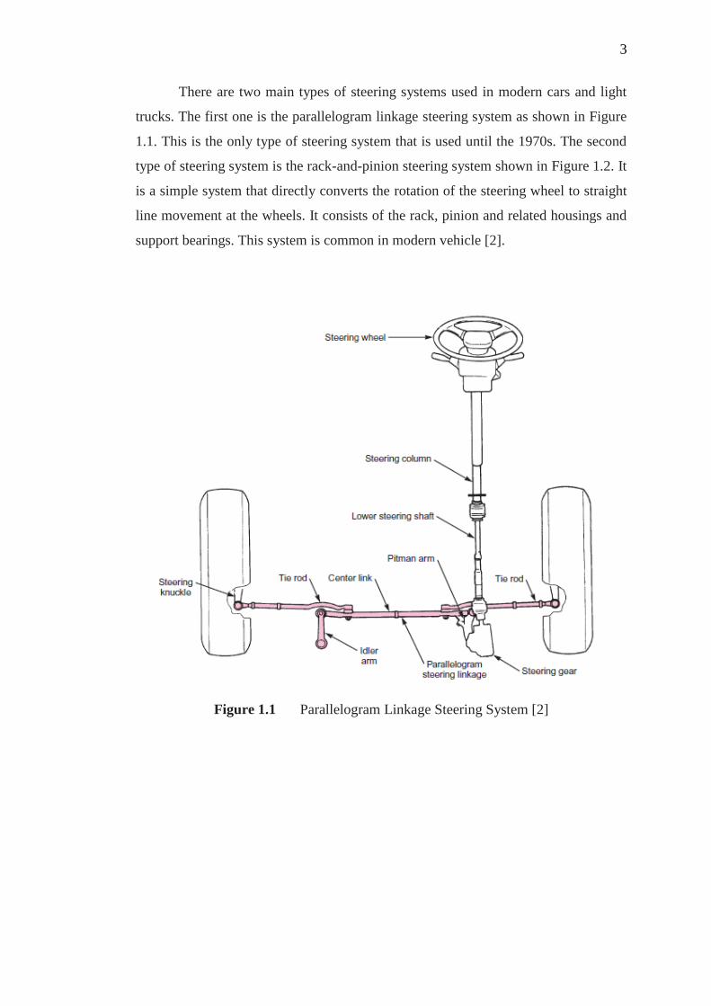
There are two main types of steering systems used in modern cars and light
trucks. The first one is the parallelogram linkage steering system as shown in Figure
1.1. This is the only type of steering system that is used until the 1970s. The second
type of steering system is the rack-and-pinion steering system shown in Figure 1.2. It
is a simple system that directly converts the rotation of the steering wheel to straight
line movement at the wheels. It consists of the rack, pinion and related housings and
support bearings. This system is common in modern vehicle [2].
Figure 1.1 Parallelogram Linkage Steering System [2]

4
Figure 1.2 Rack and Pinion Steering System [2]
1.1.2 Steer-by-Wire (SbW) System
The SbW system is a relatively new technology that is being contemplated by
researchers in automotive industry as the alternative to replace the conventional
steering systems that are currently being used in the industry. In conventional vehicles,
the steering wheel is connected to the front wheels of a vehicle through a link that can
be mechanical, hydraulic or a combination of both system [3]. The SbW system
eliminates such a link thus, the steering command is transmitted by a communication
network to the front wheel. The orientation of the front wheel is controlled by
electronic actuators based on electrical signal from the controllers, as shown in Figure
1.3[1].
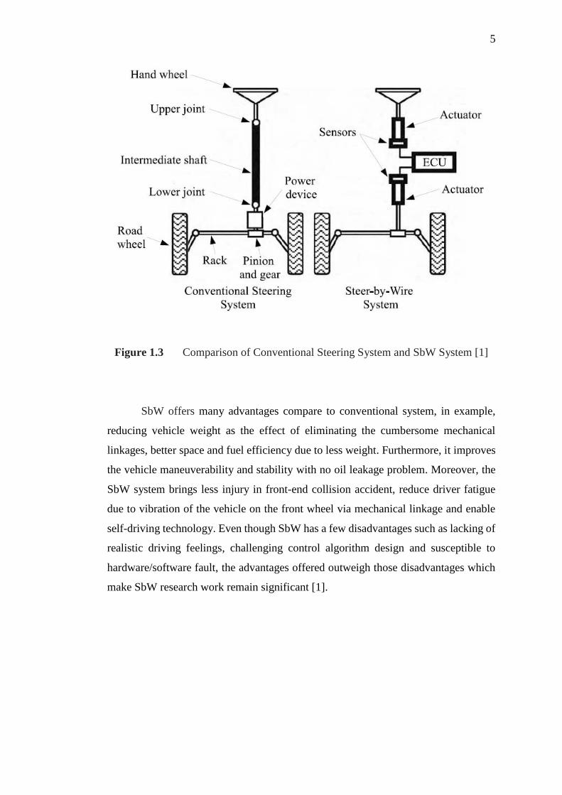
5
Figure 1.3 Comparison of Conventional Steering System and SbW System [1]
SbW offers many advantages compare to conventional system, in example,
reducing vehicle weight as the effect of eliminating the cumbersome mechanical
linkages, better space and fuel efficiency due to less weight. Furthermore, it improves
the vehicle maneuverability and stability with no oil leakage problem. Moreover, the
SbW system brings less injury in front-end collision accident, reduce driver fatigue
due to vibration of the vehicle on the front wheel via mechanical linkage and enable
self-driving technology. Even though SbW has a few disadvantages such as lacking of
realistic driving feelings, challenging control algorithm design and susceptible to
hardware/software fault, the advantages offered outweigh those disadvantages which
make SbW research work remain significant [1].
6
1.1.2.1 Steer-by-Wire (SbW) System Requirements
There are main several requirements for SbW system [4]:
1. Directional control and wheel synchronization.
- The front wheel follow the driver input command from the steering wheel.
2. Capability of steering wheel return or free control.
- The steering wheel should return automatically to the centre if the hands of
driver is removed or released from the steering.
3. Variable steering ratio.
- The steering ratio between steering wheel angle and front wheel angle. For
example, steering ratio 10:1. By means steering wheel it to 10 degrees
angle, the front tire wheel should turn to 1 degrees angle.
4. Adjustable variable steering feel.
- The vehicle driver relies on steering feel to sense the force of road condition
with tire to ground contact and maintain control of the vehicle.
This project is only focused on the directional control and wheel synchronization of
the SbW system.

7
1.2 Problem Statement
The delay that occurs in the network between sensors, controller and actuators
of a Steer-by-Wire (SbW) system leads to performance deterioration and at worst,
destabilizing the SbW system. It is harmful to the vehicle because it affects the vehicle
performance and stability and directly, the safety of the driver and passengers cannot
be guaranteed.
1.3 Objectives of the Project
The objectives of this project are:
1. To adapt the mathematical model for the SbW system from existing work.
2. To adapt the Proportional-Integral-Derivative (PID) control algorithm that can
compensate delay for the SbW system under Controller Area Network (CAN)
from existing work.
3. To analyse and evaluate the performance of the proposed PID controller
algorithm on SbW system connected in the CAN network protocol.
8
1.4 Project Scopes
This project is solely based on the software simulation development to implement the
designed PID that can compensate delay control method on the SbW system.
The scopes of the project are:
1. SbW system model for vehicle with front wheel drive only.
2. CAN protocol as the network system interconnecting the components of the
SbW system.
3. PID controller that can compensate delay as the controller of the system.
4. Simulation is done using the Matlab/Simulink with Truetime toolbox.

9
1.5 Outline of Thesis
The thesis report is organized in 5 chapters. The first chapter gave an overview
of the project that provides a brief description about the subject of study, the problem
statement, the objective, and the scope of this project.
Chapter 2 covered literature review on SbW system, related works and
controller design. It contains the previous research works done in the area of SbW with
difference in controller design methods which brought out a few motivation in building
the framework of this project works.
The third chapter covers the flow of methodology and description of each
procedure. It starts with the modelling of the SbW system derived from existing work.
Then, the control strategy and control method of the SbW model is formulated based
from the previous works with the aim to compensate delay.
Chapter 4 mainly present and discuss the simulation results of the performance
of the SbW system with PID controller in the CAN network protocol.
The conclusion of the project is discussed in chapter 5. It covers the whole
perspective of the project and with some recommendations for the research on the SbW
system under network control to be considered in the future work.

82
REFERENCES
1. Nor Shah, M. B., Husain, A. R. and Dahalan, A. S. A. An Analysis of CAN-
based Steer-by-Wire System Performance in Vehicle. IEEE International
Conference on Control System, Computing and Engineering. Penang,
Malaysia: IEEE. 2013. 350–355.
2. Johanson, C. and Stockel, M. T. Auto Suspension and Steering Textbook. 3rd.
ed. Tinley Park, Illanois: Goodheart-Willcox Publisher, 2010.
3. Bertoluzzo, M., Buja, G., Menis, R. and Sulligoi, G. An Approach to Steer-by-
Wire System Design. IEEE International Conference on Industrial
Technology. Hong Kong: IEEE. 2005. 443–447.
4. Tau, Y. Vehicle Steer-by-Wire System Control. SAE Technical Paper. 2006-
01-1157, 2006
5. Zhang, X., Kong, H. and Wang, H. A Composite Control Scheme for
Automotive Steer-by-Wire System. International Conference on Modelling,
Identification and Control, Melbourne, Australia. 2014. 237– 242.
6. Fahami, S. M. H., Zamzuri, H., Mazlan, S. A. and Zakaria, M. A. Modelling
and Simulation of Vehicle Steer by Wire System. IEEE Symposium on
Humanities, Science and Engineering Research. Kuala Lumpur, Malaysia:
IEEE. 2012. 765–770.

83
7. Oh, S.-W., Chae, F.-C., Yun, S.-C. and Han, C.-S. The Design of a Controller
for the Steer-by-Wire System. JSME International Journal. 2004. 47(3). 896-
907.
8. Im, J., Ozaki, F., Matsunaga, N. and Kawaji, S. Bilateral Control for Steer-by-
Wire Vehicle. SICE-ICASE Internal Joint Conference, 2006.
9. Amberkar, S., Bolourchi, F., Demerly, J. and Millsap, S. A Control System
Methodology for Steer-by-Wire Systems. SAE Technical Paper Series. 2004-
01-1106. 2004.
10. Do, M. T., Zhihong, M., Cishen, Z., Wang, H. and Tay, F. S. Robust Sliding
Mode-Based Learning Control for Steer-by-Wire Systems in Modern Vehicles.
IEEE Transactions on Vehicular Technology. 63(2). 2014. 580-590.
11. Daher, N. and Ivantysynova, M. An Indirect Adaptive Velocity Controller for
a Novel Steer-by-Wire System. Journal of Dynamic Systems, Measurement,
and Control. 136(5). 2014. 1–9.
12. Hai, W., Zhihong, M., Weixiang, S., Zhenwei, C., Jinchuan, Z., Jiong, J. and
Do, M. T. Robust Control for Steer-by-Wire Systems with Partially Known
Dynamics. IEEE Transaction on Industrial Informatics. 10(4). 2014. 2003–
2015.
13. Jianmin, D., Ran, W. and Yongchuan, Y. Research on Control Strategies of
Steer-by-Wire System. International Conference on Intelligent Computation
Technology and Automation. 2010. 1122–1125.
14. Pimentel, J. R. An Architecture for a Safety-Critical Steer-by-Wire System.
Society of Automotive Engineers Technical Papers, 2004.
15. Chaaban, K. and Leserf, P. Simulation Of a Steer-By-Wire System Using Flex
Ray-based ECU Network. International Conference on Advances in
Computational Tools for Engineering Applications. 2009. 21 – 26

84
16. Jianmin, D., Hualin, D. and Yongchuan, Y. Co-Simulation of SBW and
FlexRay Bus Based on CANoe_MATLAB. IEEE International Conference
on Automation and Logistics. 2010. 202–206.
17. Veeramachaneni, S. R. and Watkins, J. M. Robust Performance of PID
Controllers for Time-Delay System with a Smith Predictor. American Control
Conference. 2014. 2462–2467.
18. Mirzal, A. Stability Analysis and Compensation of Time Delays in Analog
Control Systems. International Journal of Control and Automation, 5(4). 2012.
1–17.
19. Maqsood, I., Nasir, H. A. and Muhammad, A. PID Controller Tuning for
Networked Delayed Motion Control. International Conference on
Communications, Computing and Control Applications. 2011.
20. Xiangdong, D. and Qingling, Z. Stability and PID Control of NCS with Time-
Varying Delay and Data Packet Dropout. Proceeding of Chinese Control
Conference. 2010. 4417–4422.
21. Eriksson, L. PID Controller Design and Tuning in Networked Control System.
Ph.D. Thesis. Helsinki University of Technology; 2008.
22. Pohjola, M. PID Controller Design in Networked Control System. M. Sc.
Thesis, Helsinki University of Technology; 2006.
23. Nilsson, J. Real-Time Control Systems with Delays. M. Sc. Thesis. Lund
Institute of Technology; 1998.
24. Nguyen, B.-H. and Ryu, J.-H. Direct Current Measurement Based Steer-by-
Wire Systems for Realistic Driving Feeling. IEEE International Symposium
on Industrial Electronics. 2009. 1023–1028.

85
25. Anwar, S. and Chen, L. An Analytical Redundancy-Based Fault Detection and
Isolation Algorithm for a Road-Wheel Control Subsystem in a Steer-by-Wire
System. IEEE Transaction on Vehicular Technology. 56(5). 2007. 2859–2869.
26. Isaksson, A. J. and Graebe, S. F. Derivative Filter is an Integral Part of PID
Design”. IEE Proceedings: Control Theory and Applications. 61(149). 2002.
27. Åström, K. J. and Hägglund, T. PID Controllers: Theory, Design, and Tuning.
2nd Edition. Instrument Society of America, Research Triangle Park, North
Carolina, 1995.
28. Bosch, R. GmbH, CAN Specification: Version 2.0. Stuttgart, Germany. 1991.
29. Cervin, A., Henriksson, D. and Ohlin, M. TrueTime 2.0 Beta – Reference
Manual. Department of Automatic Control. Lund University. Sweden. 2010.
30. Cervin, A., Henriksson, D., Lincoln, B., Eker, J. and Årzén. K. E. How Does
Control Timing Affect Performance? Analysis and Simulation of Timing
Using Jitterbug and TrueTime. IEEE Control System Magazine. 23(3). 2003.
16-30.
31. Jie, T., Jin, W. and Ning, C. Fractional PIλDμ Control for Steer-by-Wire
System. Advanced Material Research. 279. 2011. 423–428.
32. Xuyun, Q., Mingjin, Y., Zhulin, Z. and Jiuhong, R. Research on Steering
Control and Simulation of Vehicle Steer-by-Wire System. Advanced Material
Research. 403–408. 2012. 5076–5081.
33. Hayama, R., Kawahara, S., Nakano, S. and Kumamoto, H. Resistance torque
Control for Steer-by-Wire System to Improve Human-Machine Interface.
Vehicle System Dynamics: International Journal of Vehicle Mechanics and
Mobility. 48(9). 2010. 1065–1075.
34. Yun, Y. J., Feng, K. and Yuan, W. F. Control Strategy for Front Wheel Angle
of Steer-by-Wire based on Variable Steering Ratio. International Conference
on Computer Science and Network Technology. 2011. 852–856.
86
35. Bertoluzzo, M., Buja, G. and Menis, R. Control Schemes for Steer-by-Wire
Systems: Design and Experimentation Issues for Improved Control of Steering
Maneuvers,” IEEE Industrial Electronic Magazine. 1(1). 2007. 20–27. 2007.
36. Tavoosi, V., Kazemi, R. and Hosseini, S. M. Vehicle Handling Improvement
with Steer-by-Wire System Using Hardware in the Loop Method. Journal of
Applied Research and Technology. 12. 2014. 769–781.
37. Yixin, Y. Vehicle Steer-by-Wire System Control. SAE Technical Paper
Series. 2006-01-1175. 2006.
38. Saruchi, S. A., Zamzuri, H., Mazlan, S. A., Fahami, S. M. H. and Zulkarnain,
N. Wheel Synchronization Control in Steer-By-Wire Using Composite
Nonlinear Feedback. Applied Mechanics and Materials. 575. 2014. 762–765.
39. O’Dwyer, A. PID Compensation of Time Delayed Process: A Survey.
Proceedings of the Irish Signals and Systems Conference. 2000. 5–12.
40. Ait-Oufroukh, N., Messaoudene, K. and Mammar, S. Dynamic Model of Steer-
by-Wire System for Driver Handwheel Feedback. IEEE International
Conference on Networking, Sensing and Control (ICNSC). 2013. 780–785.
41. Fangyuan, W., Feng, K. and Jiangyun, Y. Intelligent Fault Diagnosis of Steer-
by-Wire Automobile. Journal of Computers. 7(5). 2012. 1204 – 1211.
42. Balachandran, A. and Gerdes, J. C. Designing Steering Feel for Steer-by-Wire
Vehicles Using Objectives Measures IEEE/ASME Transaction on
Mechatronics. vol. 20(1). 2015. 373–383.
43. Xiaoran, S., Fang, L. and Chenglin, L. Network Level Fault Diagnosis of Steer-
by-Wire System based on ANFIS. IEEE Conference and Expo Transportation
Electrification Asia-Pacific (ITEC Asia-Pacific). 2014. 1–5.
87
44. Mane, S. P. S., Sonavane, S. and Shingare, P. P. A Review on Steer-By-Wire
System Using Flexray. International Conference on Wireless Communication,
Vehicular Technology, Information Theory and Aerospace and Electronics
Systems Technology (Wireless VITAE). 2011. 1–4.
45. Kleine, S. and van Niekerk, J. L. Modelling and Control of a Steer-by-Wire
Vehicle. Vehicle System Dynamics: International Journal of Vehicle
Mechanics and Mobility. 29(1). 1998. 114–142.
46. Bajçinca, N., Cortesão, R. and Hauschild, M. Robust Control for Steer-by-Wire
Vehicle. Journal of Autonomous Robot. 19(2). 2005. 193–214.
47. Hibi, M., Kobune, T., Miki, D., Kano, Y. and Abe, M. A Study on Steering
Reactive Torque for Steer-by-Wire Vehicle Using Driving Simulator.
Proceedings of the FISITA 2012 World Automotive Congress: Lecture Notes
in Electrical Engineering. 10. 2013. 237–246.
48. Sadale, R., Kolhe, R., Wathore, S., Aghav, J., Warade, S. and Udayagiri, S.
Steer-by-Wire Implementation Using Kinect. Proceedings of International
Conference on Advances in Computing. 2012. 163–170.
49. Li, Q., Shi, G., Wei, J. and Lin, Y. Yaw Stability Control of Active Front
Steering with Fractional-Order PID Controller. International Conference on
Information Engineering and Computer Science. 2009. 1–4.
50. Mulder, M., Abbink, D. A., Boer, E. R. and van Paassen, M. M. Human-
Centered Steer-by-Wire Design. IEEE International Conference on Systems,
Man, and Cybernetics. 2012. 3015–3019.
51. Hussain, K., Baharom, M. and Day, A. Analysis of The Properties of A
Steering Shaft used as a Back-Up for a Steer-by-Wire System during System
Failure. Proceedings of the Institution of Mechanical Engineers, Part D:
Journal of Automobile Engineering. 223(2). 2009. 177–189.
88
52. Shaheen, S., Heffernaan, D. and Leen, G. A comparison of emerging time-
triggered protocols for automotive X-by-wire control networks. Proceedings
of Institute of Mechanical Engineers: Part D: Journal of Automotive
Engineering. 217. 2003. 13–22.