Embed Size (px)
Citation preview

CHAPTERI
Properties of Ferro magnetic MaterialsSometimes the best \ vay to realize the value of any object is to try to
imagine what \ vould happen if it \ vere taken a \ vay . If the iron and steel
in dynamo - electric machinery , po \ ver and audio - frequency transformers ,
telephone receivers , relays , loudspeakers , and hundreds of other electromagnetic
devices should suddenly lose their magnetic properties , these
devices could no longer function properly . It is hard to imagine how
\ vithout these materials ne \ v designs could be made \ vithin a reasonable
range of space and cost . Obviously , any substance \ vhich permits a large
flux density for a specified magnetizing force or \ vhich makes possible
the constraint of flux to definite desired paths is bound to be of inestimable
value to the designer . These properties are found in certain forms
of iron and its alloys \ vith cobalt , tungsten , nickel , aluminum , and other
metals , \ vhich are called the ferro magnetic materials . Easy to magnetize ,
such substances \ vhen used for the cores of apparatus make possible
flux densities ....vhich are hundreds or even thousands of times greater
than could be conveniently established with a practical coil \ vithout the
ferro magnetic core .
1 . IM : PORTANCE OF FERROMAGNETIC MATERIALS
The commercial importance of ferro magnetic materials is indicated by
the thousands of tons produced annually , comprising a wide range of
physical and magnetic properties . The materials are available commercially
in numerous forms such as sheets a fe , v thousandths up to
about one - fourth inch thick , as wires a few thousandths up to about
one - fourth inch in diameter , as bars of various cross - sectional shapes ,
and as castings , , - eighing a fe , v ounces up to several hundred tons for
use in machines or other devices .
The fields of application of these materials , which are discussed briefly
in Art . 6 , are so broad and the requirements of each application are so
different that engineers , physicists , and metallurgists have had to develop
a wide range of ferro magnetic alloys , each having particular qualities
valuable in specific applications . The value of these accomplishments
can hardly be overestimated , and many of the recent , perhaps startling ,
developments in the design - technique of electrical machinery have
arisen because better materials have been made available by metal -
lurgical research and because the engineer has utilized physical and
magnetic properties to better advantage . To emphasize this point , it
,~ h . ould be noted that the basic electromagnetic phenomena in a modern
3

-
0 " ' " d rot
- . . o . . . . ~
n . . . . 0 ~
~
~
rot
- N
. . . . . . . . - . rot
- p . . ~
p . J n C / J 0 ' " d . . . . ' " d 0 ' " 1 ~
~
~
~
~
0 ~
~
~
' - : : ' " 1 P " " ~
( " " to
P " " p . J p . . ' " 1 0 ~
p P " " . ~
~
0 0 . . . . . ~
~
~
n - . ~
~
p . J - . ~
p ~
' " 1 P
; : j : J - . 0 \
-
~ : ; ~
( i J p . J n . . . . S
~
( 5 . 0 ' ; 1 " . ~
~
~
. , d " " " B
( " " to
~
p . . 0 . . . B
t : j ~ . rot
- ~
( " " to
~
- . ~
~
tr1
( J3 . ' ; 1 " . ~
n p . J ~ CJ1
I . . - . u ( " " to
~
~
n ~
~
C / J ~
P " " " " " ' : j . - . . p . J P
P " " ~
( ? . . . . . ( ? 0 " ' p " " ' " P " " ' " ~
( i J ~
~
~
( ? C / J " " ' . . . . . . < : : >
~
~
~
~
P " " ' ; 1 " . ~
P " " ~
( " " to
~
5 ~
~
~
~
< : : ~
~
~
C / J ~
; . ~
- . 5 . ~
S
Q
5 ~
C / J ~ . ( Jq
Q
C / J ~
H - . < : : >
~
. ~
' : ! : . g ~
~
0 . . . ~
p . J ~
p . J . ' ; 1 " . 2 - ~
M
3 . ' " 1 , . . . , . . . Q
5 . S
Q
( J ~
~
( J ~
n ~
n ~
g e ? - . 5 . ~
0 @
( " " to
E : : ! : . ?
.
' ; : : j 0 " ~
' " 1 ( " " to
> <
~
~
C / J o ' ~
0 n ~
I : : : : : ! 0 ~
n p ( : > " " " ~
0 5 ( " " to
~
. . . . . ~
Q
: : : : ; . ro
P
( " " to
C / J ( ? C / J - . ' " d ro
~
2 ' ro
o
C / J " <
< . ' " d ~ . u ( " " to
~
~
~
~
0 ~
p . ; P " " C / J n 0 . . . ~
P " " ~
( " " to
~
' " 1 n ' " 1 ~
5 . ~
Q
. C / J S
rot
: j <
0
n 0 C / J ro
~
~
~ . 0 p . J ro
P
( " " to
' " 1 ~
~
. . . . ( " " to
o . ~
ro
~
Q
Q
. . . . . ~
~
( ] q ( ] q ~ ~ . r ; : : ' " 1 P
~
~
~
. . . . - . ( " " to
I - - " . . . . ( J ~
C / J 0 0 ( J ~
p . J ~
( " " to
rot
- ' " d C / J ~ . - . ~
' " d " <
> <
~
C / J H - . <
~
n ~
' " rot
- - . 0 ~
:: r " ! : I - ~
" <
~
~
. - . 0 0 ( " " to
~
( " " to
0 P " " r ; : : - . n : : : : . ~
' " " ' " 1 ~
( " " to
~
P " " Q
: : : : . ~
( J ~
? . . P " " OS
~
CJ
; Q
al ' " - J
-
- = - , r I - - " . ( " " to
. . . . . . . . . ~
- . ro
0 G
' " 0 ~
. . . . " " " " , 0 ' " ' n . 0 - ' . . . . . rot
- . . . . C / J C / J ~
' " ' "
~
f . ) P " " . . . . . P " " ( J ~
~
P
( " " to
' " 1 p . . f - = j c5
' " 1 ' " 1 . . . . . . Q
. . . . ' " 1 ~ . . . . . , ( " " to
0 , . . . n . . . . . Q
C / J , . . . ~
~
~
I - . . .
~
. . . . ro " " " H
. . . . - - - " " . . . ( " " to
. . . . . . . . . . C / J ' ro
0 u ~
I - - " H
( " " to
. . . . p " " n . . . . . . . . . . . . . . " ro
\ J
I- j ' ( t ; ~ ~ ~ ~ , , J ~ e . . P " " p " " ~ ~ Q
~
' " 1 . ( " " to ( ? ' " d - . Q ~ , , < - . ( " " to
Q ( " " to ( " " to
p . J3p
. Jp " " ' " 1 ~
~
~
~
( J ~
o ! d ~
~
~ : [ : g ; ( J ~ : g . ~
~
~
~ ~ . ~
~ . ~ . ~ . g . s ' %
~o " " " . g ~
~
~
~
2 - ' 3 @
~
~
~
"" : : r " ro
' " 1 . . . . . 0 ( " " to
C / J ro
p " " ' " 1 ~
. . . . L , . . . ~
0 , . . " " " " " ~
~
Q
~ . . . . . ( " " to
( " " to
<
~
~
~
U) [ jj . ' " 1 , . . . , . . . rr : ; ~
- . ro
0 C / J ro
: : ; - : C / J ~
~
M
~
~
- - - " " ~
~
' " 1 ( ] q 0 ( " " to . 0 " ' p . . ~
~
~
~ . n . . o o ' 0 Q
n . - . . p . J C . , )
.. . . . . . . U
( JJ
( ? ( " " to
, . . . , . . . Q
P
' - - ' ~
~
' " 1 . . . . ' " d ( " " to
- . ~
Q
' " ' 0 ~
0 . . . ~
I ~
. . . . . ~
p " " - . ' " 1
f. ) f . ) ~
ro
0 ~
0 Un
~
C / J ' " d " , ( " " to
~
( Jq
~
rot
- . ( ? 0 . . . . . " " ' . . . . . . ~
U
C / J . - . . n ~ . . . . ~
~
. . . . . " , ro
.. . . ~
. - . . b " " 0 <
ro
0 ~
rot
- ' " 1 . - p " " . . . . . . . . . . . . . C / J . . . . rot
- Q
' " 1 . . . . . I - - " 0 C / J " " . . . . . . Q
ro
. . . a
~
; : : ; . ( JJ ~ . - . 0 " ' ~
, ~
0 ~
( ? cn
rD
~
0 Z
0 ~
~
p " " C / J ( ? . . . . . ~
~
~
ri ~
8 . . 0 - ' ~
<
n ; ' ' : t ' j
-
~
~
( " " to
C / J " <
0 " ' ~
rot
- . J ~
: : : : p . . " <
~
rot
- ~
~
- . " " . Q
Q
( " " to
~
" " " ~
0 ~ . . . . . Q
( " " to
Q
ro
ro
g. ~ . ~ : : : : J . . p " " ~
~
B . ~
: . ~
P
~
0 ' g . . . . . { jj . S
0 ~
: : : : . g 0 . . . ~
~
eo : ~
~
; . ( " " to
~
H - . ~
~
~
C / J 0 . . . ~
C / J ' : t ' j
~
U ) , - ; rot
- ( ? . . . . . ' " 1 . . . . - . ~
C / J n ~
- " " ' . . . . ~ . . . . . . . " " " . . . . . ' " 1 ro
0 rot
- ( ? . . . . . " " ' , . . . ~
~
~
' P
. . . . . . p " " ~
( t C / J ( J ~
E . . " ' . ' ; 1 " . . . . . ( ? - . . . . . ~
t : j ~
( ? 0 rot
- ~
( 3 . " <
rot
- 0 " ' ~
~
~
g - < . n ~
~
~
~
S
~
'3 " 7J " S . ( t ; 0 . . . p " " p . J ~
~
g p . . ; . 0 { jj . 0 " ' ~
0 ~
- . ~
0 C / J ~
<
~
~
q Q
p " " Q
q ~
( " " to
rot
- " <
ro
~
S
~
. . . . . ~
5 . r ; ; f ; ; ~
~
n rot
-o " " . p . . S
Q
S
p . . ~
( J ~
~
~
; . S
~
~ : g ~
c - t - " <
, . . . 8 - ~
0 . . . Q . ~
~
~
rE
~
. 9
"" ' - . . . n ~
. . . . . ' " " ' . . . . . ro
' " ro
, . . , " ' " 0 " " . ~
. . . . . . . . . . . . . . . . . . . . . . ' " Q ' " ' " ' V ' o ( C / J " " " '
a' i f . ) ~
~
< : : " - . 0 - ' ~
( ? ' " 1 ~
. . . ~
cn
c - t - " " . . 0 . . . C / J <
( J ~
~
' " 1 Q
C / J . . . . . ' " d . . . . . . . . . C / J " " " . . . . . . ~
I - - " 0 . . . . . ~
~~
' " " O8
o - ' ~ go
n ~ ~ ~ ~ n ~ ~ c ; " ' ~ C / J ~ ~ oQ ~ qp . . ~ ~ ~ . ~
~
': ! . . z C / J c - t - n rr ; ; 0 c - t - ~
8 . . " <
~
~
: : ! . <
o ' f . ~
p " " p . . rot
- Q
p ' ~
0 ~
~
o . 0 ~ . ( ? ~
( J ~
( ] q ~
~
~
n
q . . . . ro
0 . . . ~
~
' " ' , ~
: : ; - : 0 " ' . . . . A
~
~
~
c - t - 0 . rot
- . . . . . c - t - p " " c - t - ri - . ~
< : : ~
~
Q
p " " < ,
~
~
" <
3 ! ; f1 . . o : : : : J . . ~
C / J . . . . . ~
. . . . . .3 ~
~
8 . . ~
~
. . . . . . . . . . Q
' " Ij p " " s 2 . . E : : ! : . Q
. . . . . p " " ~
c - t - . . . . o ' ~
Q
~
~
' y ' ~
:: r " 9 . ' " d ~
G
n ~
ro
ro
. . . . . . ~
riP
rot
- ~
Q
S
~
. . . . . <
n Q
. . . . . p " " 0 ( ? ~
~ . ~
. . . . . ~
~
g
; : j . , ' " 1 p " " e . . <
~ . ~
( J ~
~
' " Ij S
~
S
. . . . = = - ~
rot
- o ' ' " 1 ~
~
~
c - t - Q
p " " c - t - ~
~
C / J 5 . n ~
~
~
. . . . .
~
5 : ; 3 ~
9 ; : ; " 2 . . 8 ' " " 0 nO " ' ~ ' ' " d ~
~
N . H - . < . ~
. . . . . ~
~
SO
; ; S ' ~
H - . 5 Q
Q
0 n ( ] q ~
9 - q - ( " ' )
" ' 0 ( t ; Q
<
~
0 . . . . . . . . . . . ~
C / J Q
c - t - ' " d ( J ~
c - t - p . J ~
~
C / J ~ . ' " 1 ~
~
~
( : > " " " 0 . . . - . 0 ~
. . . . . ro
l ~ J
'0 ~
C / J ~
( t ; rot
- ' " 0 rot
- ~
. : : ! r ; ' ; ~
C / J ' " 1 ~
p " " ~ . ' " d p . ; rot
- ' " 1 ~ . . . 0 ~ Q
C / J <
( J ~
~
Q
c - t - ~
0 0 . . . ~
~
p . . ~
~
n ( t ; ~
. . . . . . Q
0 I - - " . . . . 0 ( ? ( ? 0 ' " 1 p . . c - t - - ( ? . . . ~
. . . . ~
~
P
p " " c - t - - . ( ? C / J . . . . .
.
~
~
~
< : : p . . 0 2 ~
: : : : ~
' " d c - t - . . . . . . 0 " , ro
~
0 . . ' c ; j ~
rot
- ~ . ' " 1 . . . . ( ? < . Q
~
0 C / J ro
C / Jo
~
~
=
. . . . . ~
' " 1 ( i ) c - t - rf ) . . . . n ~
c - t - , j { jj . , . . J , . . J 0 - ' ~
~ . ' " 1 . . . p " " ( J . . . . . c - t - ~
n . . . . c : . c - t - ~
. . . . . " - ' 1
~
g S
~
' 0 q S
p " " ~
' ; ; ; ro
0 ~
~
S
~
: : : ( : > " " " ~
e . . ~
S ~ . ( ? ~
~
~
c - t - ~
o . 8 . ~
p " " ' " 1 ~
~
~
~
. . . . ' " d 0 . . . ~
ro
p " " ' " 1 . . . . . c - t - - . S
~
C / J 0 p . . ~
c - t - " " " I ( ? p " " ' ' " 1 ~
C / J ro
Q
n 0 : ~
.
~
' ( 3 S . ro
p . J ; . ' " 0 o ' ~
( ? ~
c - t - ~
p . J p . ; c : . C / J ' " 1 0 ' " 1 ~
C / J ~
= = - : ~
~
~
H
B
( J ~
Q
' " 1 0 . . . ~
. . a . . . . .
"" 1 ~
. . . . < : : ~
' " 1 ~
- - . . C / J ( Jq
p " " ~
' " 1 , . . J Q
- . Q
~
c - t - ~ . ~
e . . p " " 0 C / J ~
. . . . . - . ' " d ~
' " d 0 ~
.. . - = - ~
c - t - ( ? ' " ' Q
( ? . . . . . . p " " ~
( J " ro
0 0 . . . . - ro
c - t - r . . - , n ' " ' ~
, . . . , . . . < : : ; : : i , . . . ro
. . . . . . . c - t - Q
' " d p " " Q
p . J . . . . . . t ' " 1
~
S
" , ~ . . . . . . ~
C / J C / J ~
' ; : : ; : " 0 - . 0 V ' o ( ~ . . . . . . C / J un . . . . p . J c - t - ' " 1 ' " 1 " <
n p . J C , , )
~
f . ) S
ro
~
C / J c - t - n ro
C / J ~
~
c9 : c - t - ( : : ? . . ' " d 0 - ' < . . . . . ~
c - t - ro
Q
E . . 3 . S . ; . ~
' " d 8 . g C / J SH
- . ' " 1
~
: S
S
0 ~
c - t - g >
' ; : : : j ' rr : ; ~ ~ . . CD
~
Q
: : ~
g - ~
g . q - . p . . Q
~
' " d ~
S
~
n . ~
" <
~
-. . ; ~
rot
- p . J ro
S
Q
c - t - n ~
0 0 . . . 8 . . <
~
~
c - t - ~
. . . . . ~
, . , p . J c - t - ~
~
n . . . . . ' " 1 ~
~
rot
- e . . 0 p . J ~
a' i C / J ( J ~
ro
~
p " " ( ? ~
~
ron
0 ' " 1 ~
. . . . p . . ~
- . ~
0 ~
n ~
C / J ro
~
( ] q . . . . ~
ro
~
~
P " " : 3 r ; ; ~
~
( ' ; ) ~
~ " . . J g . 5 0 . . @
3 ~
<
~
c - t - ~
P
n - . ~
p ~
~
~
( ' ; ) ~
~
~
C / J 0 . . . ~
~
w
' : ! . ~
ro
<
~
~
~
' " 1 c - t - 0 p . J - . p . J ( ? rot
- e : @
0 ' " 1 go
0 . . " " . ~
~
~
~
~
~
0 S
c - t - ( " " to
Q
;: ) 0 . . < ~ . ~ . ~
' " 1 " <
. . . . . ~ ' O
p " " ~
( JO
0 C / J ~
~
~
C / J " , ~
ro
~
ro
8 n ~
Q
n ' " 1 ~ . g ~
e ? - . p " " 0 .
~
~
ron
. . . . . . . . ro
~
c - t - C / J ~
c - t - I ' " 1 ro
p . . . . . . . . . . c - t - . . . " " ' " ~
I I . . . . Q
c - t - , " Q
C / J n - - . . I . - . . ro
' " 1 . . . . .

l '11 E Uj~1' 01" ./\lA (;lYE1'j ::>'l\/ "Art. 2]
been achieved almost entirely as a result of empirical investigation , and
only in comparatively recent times has the theory been developed to the
stage where it can serve as a reliable guide to experimentation . Only the
briefest qualitative statement of the present theory , which in its details
includes many aspects of modern atomic and quantum theory , is given
here .
Visualizing the magnetic behavior of actual samples of material in
accordance , \ ith the present concepts of magnetism involves considering
several different subdivisions of matter . ' [ he smallest particles concerned
are the components of the atom ; namely , the nucleus and its associated
electrons . Next in size are the atoms . Larger than the atom are the
domains , which are sub crystalline particles of varying shapes and sizes
having a volume of about 10 - 9 cubic centimeter and containing about
1015 atoms . \ Videly varying numbers of domains are included in acrys -
Tai , and all but very special samples of magnetic ma - v
terials contain many crystals . . . ... . .~ . . . . . . . . . . . . . . '
2a . Electrons and i " \ T uclei . - Magnetism is believed ~ ~ - ~ - - - -
to be basically electrical . \ Vhen an electric charge + q r p
q moves with a velocity . . J. , a magnetic field is set up FIG . 1 . Moving
as indicated in Fig . 1 in which . . J. shows the direction charge + q proof
motion and P indicates the point at which ' X is to duces a magnetic
be determined . If the charge is positive , and if the field ~ n the sur -
I . d h . PhI f rounding space .ve OClty vector an te pOInt are m te pane 0
the paper , the direction of ' X is away from the reader perpendicular to
the plane of the paper and its magnitude is
J ( = ~ sin ( ) [ 1 ]r
In the atom , electrons move in orbits about the heavier nucleus and
at the same time each electron , as \ vell as the nucleus , spins2 about an
axis of its o \ vn . A spinning electron or a spinning nucleus has a definite
moment of momentum ( angular momentum ) and a definite magnetic
moment . For the electron , these moments are in opposite directions and ,
for the nucleus , in the same direction . r \ n electron in an atom has , in
addition to its spin moments , a moment of momentum and a magnetic
moment due to its motion in its orbit . The total magnetic moment of
an atom is the vector sum of all its component magnetic moments .
2b . The Atom . - The latest atom model3 as conceived by the physicists
is pictured as a spinning nucleus composed of protons and neutrons
surrounded by definite numbers of spinning electrons performing certain
orbital motions . The simplest of the atoms is that of hydrogen having a
2 K . K . Darrow , " Spinning Atoms and Spinning Electrons , " BiS . T . J . , 16 ( 1937 ) , 319 - 336 .
3 LB . Loeb , . .1tomic Structure ( Ne \ v York : John Wiley & Sons . 1938 ) .

6 PROPERTIES OF FERROMAGNETIC MATERIALS [Ch. l
proton for its nucleus and a single orbital electron. The atom as a wholehas a magnetic moment composed of three parts - the magnetic momentof the positive charge spinning on its axis, that of the negative chargespinning on its axis, and that produced by the negative charge moving inits orbit . The magnetic moment associated \vith the orbital and spinmotions of the electron are of an order of magnitude one thousand timesthe magnetic moment of the spinning proton . Hence the magnetic effectof the nucleus is difficult if not impossible to detect in experiments withhydrogen atoms unless the magnetic moments of the electron can be insome way neutralized . This neutralization actually takes place in thehydrogen molecule since, in the combination of two atoms, the electronspins oppose each other as do the orbital motions. As might be expected,the two proton spins also oppose each other in some of the molecules(parahydrogen), while in the others (orthohydrogen ) the proton spinsline up in the same direction . Under ordinary conditions, about three-fourths of the molecules are of the ortho type .
According to the above discussion, parahydrogen should not have anymagnetic moment at all , but experiments disclose for it the presence ofa magnetic moment of the same order of magnitude as that of or tho-hydrogen but somewhat smaller. The explanation is that the rotatingcharges precess about the direction of applied magnetic field. An analysisof this precession shows that , regardless of the direction of orbital motionor spin, the precessional motion of all charges is such as to set up a fieldin opposition to the applied field . In the parahydrogen molecule, then,the only resultant magnetic effect is this weakening of the field due tothe precessional magnetic moments. This effect is known as diamagnetism.Orthohydrogen has, in addition to this effect, a nuclear spin moment ofsomewhat larger magnitude.
When a single electron has been removed from the hydrogen molecule,the result is a singly charged hydrogen ion. Here the neutralization ofspin and orbital magnetic moments has been destroyed, and the ion tendsto align its orbital and spin magnetic moments in the direction of theapplied field. This strengthening of the field is known as paramagnetism.Both diamagnetic and paramagnetic substances lose their magneticeffects when the external field is removed: the diamagnetic because theprecessions about a fixed direction cease when the field is removed; andthe paramagnetic because, ",ithout an external field , the magnetic moments
are so oriented, as specified by quantum considerations, that their
sum is zero. The atoms of the noble gases are diamagnetic and so also arecertain ions such as Na + , Mg + + , and CI- . The greater number ofatoms and ions are paramagnetic.
The properties of the ferro magnetic substances are not determined

7, Art. 2] THEORY OF MAGNETIS.~f
10
5
00 200 400 600 800
JC in oersteds
8 PROPERTIES OF FERROMAGNETICMATERIALS [Ch. l
100 100
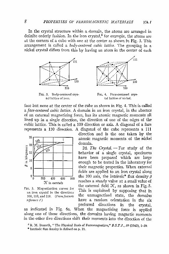
FIG. 3.
FIG. 5. Magnetization curves foran iron crystal in the directions
Body-centered crys-tai lattice of iron.
face but none at the center of the cube as shown in Fig . 4 . This is called
a face - centered cubic lattice . A domain in an iron crystal , in the absence
of an external magnetizing force , has its atomic magnetic moments all
lined up in a single direction , the direction of one of the edges of the
cubic lattice . This is called a 100 direction or axis . A diagonal of a face
represents a 110 direction . A diagonal of the cube represents a 111
direction and is the one taken by the
25 magnetic moments of the nickel
20
study the
15
fJ
in
kilo
gaus
ses
100, 110, and 111.reference 1.)
(Front footnote
atomic
domain .
2d . The Crystal . - For of
behavior of a single crystal , specimens
have been prepared which are large
enough to be tested in the laboratory for
their magnetic properties . When external
fields are applied to an iron crystal along
the 100 axis , the intrinsic * flux density { 3
reaches a steady value at a small value of
the external field X , as shown in Fig . 5 .
This is explained by supposing that in
the un magnet ized state , the domains
have a random orientation in the six
preferred directions in the crystal ,
as indicated in Fig . 6a . \ Vhen the magnetizing force is applied
along one of these directions , the domains having magnetic mom en ts
in the other five directions shift their moments into the direction of the
5 R . M . Bozarth , " The Physical Basis of Ferro magnetism , " BiS . T . J . , / 9 ( 1940 ) , 1 - 39 .
* Intrinsic flux density is defined on p . 21 .
In the crystal structure within a domain, the atoms are arranged indefinite orderly fashion. In the iron crystalS for example, the atoms areat the corners of a cube with one at the center as shown in Fig . 3. Thisarrangement is called a body-centered cubic lattice. The grouping in anickel crystal differs from this by having an atom in the center of each
FIG. 4. Face-centered cryg-Tai lattice of nickel.

applied field, as indicated in Fig . 6b. This 100 axis is called the directionof easy magnetization . If the field is applied along a face diagonal 110,four of the six magnetic moments first shift to the two directions having
components along 110 and then, with increasing field, the moments ofall domains are gradually shifted to the field direction. The 110 directionis for an iron crystal the direction of medium magnetization. Finally, ifthe field is applied along a cube diagonal 111, three of the magneticmoments shift to the three directions having
components along 111 and then a 8further increase in the field brings all the cnmoments into the 111 direction, known ~ 6as the direct.ion of hard magnetization. j 4The corresponding curves for nickel are ~shown in Fig. 7. ; 2
The presence of domains is indicated ina striking way by the photographs pro- 00 100 200 300 400duced by W. C. Elmore and sho\\n in c;r . t d. J\. In oers esFIg. 8. The three parts represent three
. f h FIG. 7. Magnetization curves forexposures of the same portIon 0 te sur- . k 1 t 1. th d. t.. a ruc"e crys a In e Irec Ionsface of a cobalt crystal under three dIffer- 100, 110, and 111. (Fro1nfoot11oleent conditions of external field. In Fig. refere11ce 1.)8a, the crystal is magnetizcd by the application
of an external field; in Fig. 8b, the crystal has been demagne-tized and in Fig. 8c the direction of the field has been reversed. Thepatterns are believed to be produced by the action of the magnetizeddomains upon a colloidal suspension of iron oxide which is placed onthe surface of the crystal and viewed under a microscope. Such arrange-
9Art. 2] TIIEORY OF MAGNETISM
. ~x ..'X
(a ) (b )
FIG. 6. (a) Domains have ma~netic moments in all six 100 clirections in an un magnet izediron crystal ; (b) in the same 100 clire\ tion when the cr)'stalis fully ma~netized in a 100clj rection.
0 (:> - ! t -
- - tE !) ! e
! 0 - - (:> t
- t ! 0 - 9
0 - 0 t - !
t ! <D - 0 -
- - - - - -
- - - - - -
- - - - - -
- - - - - -
- - - - - -
- - - - - -

/0 MATERIALSPROPERTIES OF FERROMAGNETIC [Ch. I
ments of the iron particles never take place on nonferromagnetic sub-stances, but are produced by the spontaneously magnetized domainsat the surface of an iron or a cobalt crystal even though the crystal asa whole is unmagnetized.
COIlrlesy TV. C . Elmore .
FIG . 8. Powder patterns on a plane surface parallel to the direction of easy magnetizationof a cobalt crystal (a) magnetized toward reader , (b) demagnetized , (c) magnetized awayfrom reader .
2e. Polycrystalline Substances. - A polycrystalline sample of iron orof a magnetic alloy is composed of many crystals packed rigidly togetherbut ,vith no definite directional alignment of their axes. When no externalfield is applied, each domain in such materials is spontaneously andcompletely magnetized in one of its 100 directions. The magnetic momentsof the domains in each crystal are distributed equally in the six directionsof easy magnetization , "\vith the result that each crystal is in the unmag-netized state. The random alignment of crystals produces a randomdistribution of magnetic moments throughout the material .
Imposing an external magnetic field is believed to result first in en-larging all domains having magnetic moments in the general directionof the applied field by reducing the size of adjacent domains whosemagnetic moments are in less favorable directions. The effect of thr-supposed enlargement of domains on the magnetic state of the materi "llas observed externally is very small, and predominates only for extremel)'small applied fields.

As the applied field is increased beyond the extremely small values, asecond effect becomes noticeable, in which the magnetic moments ofindividual domains are aligned in the direction of the preferred crystalaxis nearest to that of the impressed field. This effect takes place, not byrealignment of the domain as a rigid body, but by realignment of theaxes of the spins of the individual electrons within the domain from onestable direction to another stable direction . Throughout anyone domain,this realignment of spins takes place simultaneously. As the field con-
11Art. 2] THEORY OF MAGNETISM
0 X
FIG. 9. The three regions of magnetization: (a) boundary displacement, (b) sudden changein orientation, and (c) slo\v change in orientation. (From footnote refere11,Ce 1.)
tinues to be increased from the very small values, the flux density ffi isobserved experimentally tJ increase by finite jumps, each increase corresponding
to the realignment of spins in one domain. rrhis step,vise
buildup , kno,vn as the Barl,hausen effect, is illustrated by the magnifiedportion of the curve of Fig . 9. Of course, these steps do not occur in anycurve actually plotted from experimental data, but the fact that thechange in magnetization occurs in jumps can be observed by means ofa loudspeaker connected to a coil surrounding the specimen, as shownin Fig. 10. Each reorientation of a domain suddenly changes the fluxthrough the pickup coil and causes a click in the ]oudspeaker.
Because of the great number of crystal edges not parallel to the direction of the applied field , a third effect becomes apparent with externally
applied magnetizing forces greater than those required to align the domain mom en ts along the crystal edges most nearly parallel to the applied
field vector . This last mode of magnetization consists of a smooth orientation of all domain moments from the position in line ,vith the crystal
edges to the position in line ,vith the direction of the applied field . Nosharp demarcation exists bet,veen regions (b) and (c) of the curve butthe sudden jumps become less frequent as saturation is approached.

magnetizaiicn predominates, which is caused by the sudden alignmentsof groups of spins along the crystal axes most nearly parallel to the impressed
field. 1'he region for which this phenomenon principally occursis marked (b) in Fig . 9. For values of magnetizing force larger than thosefor which a pronounced Bark hausen effect occurs, the final mode ofmagnetization predominates. This mode is described as aslo ,v rotationor alignment of the domains into the direction of the field and aivayfrom the crystal axes nearest in line with the applied field. The regionfor \vhich this mode principally occurs is marked (c) in Fig . 9. The firstand last modes result in a much smaller change in flux density for a givenchange in magnetizing force than does the intermediate mode. Duringthe last mode, the iron is becoming magnetically saturated, and, whenall the domain moments are aligned in the direction of the applied field,the material is fully magnetized.
Ferro magnetic materials can be magnetized up to intrinsic flux densitiesranging from 5,000 to 25,000 gausses, have relative permeabilities of theorder of hundreds or thousands, exhibit a pronounced saturation effect,and retain some of their magnetism \vhen the field is removed. Paramagnetic
substances have very small positive relative permeabilities andlose all their magnetism \vhen the external field is removed. Diamagneticsubstances also respond weakly to magnetization , but their relativepermeabilities are less than unity .
12
magnetizing pickup coilcoil
specimen
loudspeaker
amplifier
WMoV- - - I I'Circuit connc(:tions for demonstration of Barkhauscn effect.FIG. 10.
j->R OPE R1'1 E::>' OJ,' jiERRO.~1"1(;J.V E1'j (..' .I~l AlE Rl A L) ' [Ch. l
The a,bove phenomena can be summarized briefly as Folio\vs: When agradually increasing, but small, magnetizing force is applied to a massof initially un magnet ized iron , the first mode of magnetization that predominates
is caused by the slight gro\vth in the size of domains magnetizedin the direction most nearly parallel to the applied field, at the expenseof the size of neighboring domains. A small amount of magnetizationbuilds up, and the increase takes place smoothly . The portion of themagnetization curve for \vhich this phenomenon occurs is marked (a) inFig . 9. As the magnetizing force is increased further , a second mode of

Just as the crystal of chromium is nonmagnetic* even though itsatom has six uncompensated positive spins, the crystal lattice of ironalloyed with certain other elements may not have pronounced ferro-magnetic properties. l \ lloys of this kind frequently encountered arecertain manganese and stainless steels. Specifically, an alloy comprisingabout 0.3 per cent carbon, 10 per cent manganese, 6.5 per cent nickel,and the remainder iron is essentially nonm~Lgnetic at room temperature .Curiously , however, certain ~Llloys called I Ieusler alloys, formed fromessentially nonmagnetic materi~tls, are observed to exhibit strong magnetic
properties. The most highly m~lgnetic of these contains approxi-m~Ltely 65 per cent copper, 20 per cent mang~mese, ~md 15 per centaluminum . The best specimens c~m be magnetized about as (,~Lsily ~LSlow-grade iron . Although they h~I've not found any extensi\'c commercialutilization at the present time, they have properties of marke(l interestin the development of theories of magnetism.
The preceding remarks concerning the phenomen~L of magnetizationapply chiefly to single ferro magnetic crystals and isotropic assemblies ofthese crystals in an unstrained condition . r\ sample of iron comprisingmany crystals oriented wholly at r~m(Lorn and free from strains hasproperties that are an average or composite of magnetization in alldirections of a single crystal . Frequently , ho\vever, the polycrystallineferro magnetic materi~tls used in engineering are not strain free, nor arethey isotropic ; that is, their cryst~tl ~Lxes are not ~tl \vays (]is tributed equ~tilyin every direction . Rolle(l sheet steel is ~L good i ]]ustr~Ltion of this conditionand frequently exhibits \\.ide]y different magnetic properties for differentdirections of magnetiz~Ltion. t
1'he subject of strains is closely connected \\'ith certain aspects offerro magnetic theory . For instance, the magnetic forces in ~l crystaloccurring as a result of the spins of the electrons are balanced by theelectric forces occurring as a result of the electric charges on the electrons.\Vhen a rearrangement of the magnetic vectors occurs, the balancebet\veen the magnetic and electric forces is disturbed . Consequently,the physical dimensions of the material are observed to vary . Thisphenomenon is one of many effects \vhich ha\'e to do \\'ith strains, mechanical
or magnetic, and are referred to collectively as magnetostriction.The magnetostrictive properties of iron are opposite to those of nickel .The effect of mechanical tension on iron is to increase the magnetizationfor a specified magnetizing force, \vhereas the effect of mechanical compression
is to decrease it . ,Vith nickel , the effect of tension i:3 to decreasethe magnetization for a specified magnetizing force, \vhereas the effectof compression is to increase it . \Vith iron , the length of the material
* see p. I.t See footnote 1, Ch. III .
13Art. 2] THEORY OF MAGNETISM

- -
""""' " ,;........
"' " " "
"""' ",
" " """
""" ,
4040 45 50 55 60 65 70 75 80 85 90 95 100
Exp
ansi
on
~~00"w "Z~(oj(oj !'..p.~X....,~~
(latent or residual strain ) . Where permanence of magnetization is desired, high internal strain is beneficial, because the larger the strain the
more stable is the direction of the magnetization of the domain. This condition is well borne out in permanent magnets, which frequently exhibit
magnetic hardness simultaneously with the physical hardness that istypical of a metal with large internal strain .
On the other hand, when ease of magnetization is desired - that is,\vhen a material is to have a large permeability - negligible internalstrain or magnetostrictive effect is desirable. This condition is ,veIlillustrated by the data of Fig . 11, since the nickel -iron alloys which sho\vsmall magnetostriction exhibit large permeabilities . Actually , the largestrelative permeability thus far obtained, about 600,000, occurred \vhenan alloy of 65 per cent nickel and 35 per cent iron \vas heated first inhydrogen for 18 hours at about 1,400 degrees centigrade to remove thenonmetallic impurities and to relieve the chemical strain and next atabout 650 degrees for one hour , and then \vas cooled in hydrogen underthe influence of a field intensity of about 16 oersteds. This treatment
jtJ PROPERTIES OF FERROMAGNETIC MATERIALS [ChI
increases as the magnetization is increased (positive magnetostriction ) ,whereas ,vith nickel the length decreases (negative magnetostriction ).The limiting values of magnetostriction occur simultaneously with themagnetic saturation of the material . The curve of Fig . 11 shows thesaturation magnetostriction properties of the iron-nickel alloys commonlyknown as Permalloys.
Strains are produced in a material in several '\vays, such as by cold,vorking , by the presence of impurities in the material which give riseto crystal lattice distortion (chemical strain ), or by magnetostriction
30
20
10
0
Per cent nickel in nickel-iron alloy
Saturation magnetostriction of the nickel iron alloys. (FrOl1t footnote reference 1.)FIG. 11.
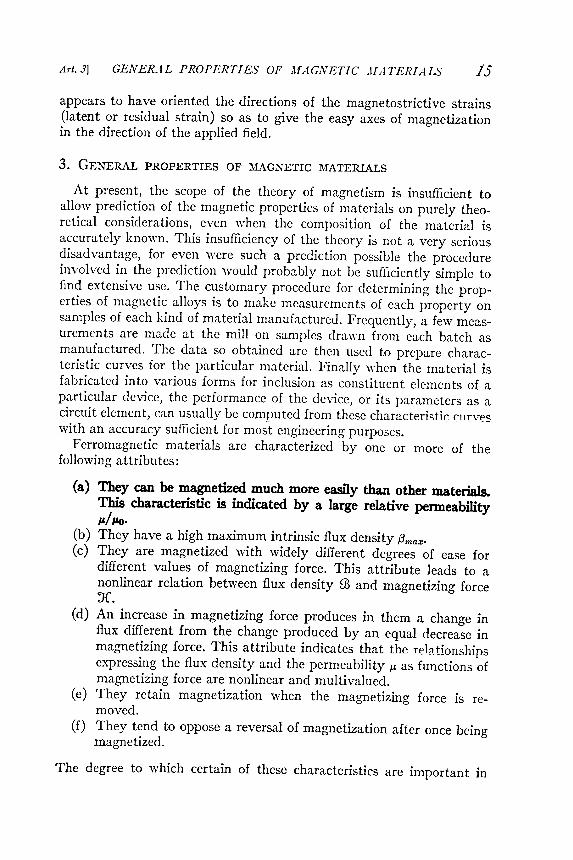
The degree to which certain of these characteristics are important in
Art. J] GENER..iL PROPERTIES OF "'f A GiVE T/ C .If.iTER/AI,:)' 15
(b ) They have a high maximum intrinsic flux density !3max.
(c ) They are magnetized \ vith \ videly different degrees of ease for
different values of magnetizing force . This attribute leads to a
nonlinear relation between flux density ill and magnetizing forceJr .
(d ) An increase in magnetizing force produces in them a change in
flux different from the change produced by an equal decrease inmagnetizing force . This attribute indicates that the rel :lti- --- __onshipsexpressing the flux density and the permeability f.J. as functions ofmagnetizing force are nonlinear and multivalued .
(e) They retain magnetization when the magnetizing force is removed.
(f ) They tend to oppose a reversal of magnetization after once beingmagnetized.
appears to have oriented the directions of the magnetostrictive strains(latent or residual strain ) so as to give the easy axes of magnetizationin the direction of the applied field.
3. GENERAL PROPERTIES OF ~{AGNETIC : MATERIALS
At present, the scope of the theory of magnetism is insufficient toallo\v prediction of the magnetic properties of materials on purely theoretical
considerations, even \\,.hen the composition of the material is
accurately kno\\.n. This insufficiency of the theory is not a very seriousdisadvantage, for even \vere such a prediction possible the procedureinvolved in the prediction would probably not be sufficiently simple tofind extensive use. The customary procedure for determining the properties
of magnetic alloys is to make measurements of each property on
samples of each kind of material manufactured . Frequently , a fe\v measurements are made at the mill on samples dra\vn from each batch as
manufactured . The data so obtained are then used to prepare characteristic curves for the particular material . Finally when the material is
fabricated into various forms for inclusion as constituent elements of aparticular device, the performance of the device, or its parameters as acircuit element, can usually be computed from these characterjstjr rllrvp ~-with an accuracy sufficient for most engineering purposes.
Ferro magnetic materials are characterized by one or more of thefollowing attributes :

I :lROPE1~16 ~TIES O}f' FERROMAGNETIC M.tl TE Rl ALS [Ch. I
particular applications of magnetic materials depends upon the circum-stances encountered in each application .
Of the materials available , iron finds the most extensive use . Its
permeability is large and its cost per pound is least of all the ferro-magnetic materials . av.ailable. ..In its commercially pure form, .it .i? .~sec Jfrequently in the structures of numerous machines. It is used also as thebase element for practically all the ferro magnetic alloys. Probably thealloy produced in the largest quantity is that composed of essentiallypure iron and between 1 and 4 per cent of silicon, depending upon thepurpose for which the material is required. \Vilen this alloy is given aparticular heat treatment , a material is obtained which , comparec I withiron , has better magnetic properties at low values of magnetizing forceand larger resistivity . As sho\vn later , both these properties are desirable.1'his alloy is rolled into sheets and strip , principally in the thicknessrange 0.014 to 0.025 inch , and annealed ; it is designated in the tradeliterature as silicon steel sheets and strip . The sheet form is convenient
for punching into many shapes used in the construction of electromagnetic apparatus. Ty~ ical shapes of punchings are shown in Fig . 12.
The silicon sheet steels used in the electrical industry are known amongsteel manufacturers U,7 and electrical designers by certain descriptivenames .
Field grade sheets contain about one-fourth of 1 per cent silicon andhave a resistivity of about 16 microhmcentimeters . This grade is usedfor smalllo \v-priced motors.
Armature grade sheets contain about one-half of 1 per cent silicon andhave a resistivity of about 19 microhmcentimeters . This grade is relatively
soft and for this reason easy to punch. It is used in small motorand generator field poles , armatures , and other devices in which highflux densities are required but core losses are not of great importance .
Electrical grade sheets contain about 1 per cent silicon and have aresistivity of about 26 microhmcentimeters . This grade is widely usedin commercial motors and generators of small and moderate sizes andmedium efficiencies, and in transformers, relays, and other devices designed
for intermittent operation.Motor grade sheets contain about 2.5 per cent silicon and ha \ .e a re-
sistivity of approximately 42 microhmcentimeters . rrhis material isused in medium-size motors and generators of good efficiencies, in control
apparatus, and in inexpensive radio transformers.Dynamo grade sheets contain about 3.5 per cent silicon and have a
resistivity of about 50 microhmcentimeters . This grade is used in high -
6 Carnegie -Illinois Steel Corporation , l ' ittsourgh , l ' a., l ~lectrical Stefl Shc(~ts, TechnicalBlllletin No . 2 ( 1941) .
7 l\ ilegheny Steel Co ., l3rackenridge , l ' a., III a.~J/etic Core III a.terials Practice (1937) .

Art . 3 ] GEJ .VERAL PROPERTIES OF ..1I ./1GiVETIC ..lI ...1TERIALS 17
efficiency motors and generators , small power - distribution transformers ~
and radio transformers .
Several transformer grades are available , the principal ones being
designated 72 ( radio C ) , 6S ( radio B ) , 58 ( radio f \ ) , and 52 . The nUffi -

18 MATERIALS [Cis.!PROPERTIES OF. FERROMAGNETIC
Because of the multitude of ferro magnetic alloys available at the
present time , to mention the properties of more than a fe \ v of those frequently
encountered \ vould be impractical . Certain properties of a
selected group of the more common alloys , and some of their fields of
use fulness are discussed in Art . 6 ; but , before these matters are considered ,
the properties of the magnetization curves of typical ferro magnetic
materials when subjected to a direct magnetizing force will be investigated
more fully .
4 . CIIARACTERISTICS AND MAGNETIZATION CURVES OF : MAGNETIC
MATERIALS
The relation between the magnetizing force X and the flux density
or magnetic induction ill which it produces in a ferro magnetic material
is of considerable importance in the engineering uses of the material . It
is most conveniently expressed by means of characteristic curves . S . 9
For purposes of explanation , a ferro magnetic material is consiclered to be
placed in a region \ \ ' here the magnetic field intensity can be varied . A
possible arrangementl O consists of a toroidal ring of the material on which
is wound a coil of \ \ ' ire as in Fig , 13a . The magnetizing force is varied
through changing the current in the coil . The material is originally de -
magnetized . If the flux density ill is measured by an appropriate method ,
as a function of the magnetizing force X for values of X up to a maximum
, say + Xmax , and the relation is plotted , a curve similar to oab of
Fig . 13a is obtained . This curve is sometimes referred to as the rising
magnetization curve . If X is now decreased , a different relation bet \ veen
ill and X is found , as is typified by the curve bc , which lies above the
rising curve . A flux density , given by oc on the plot , remains when ' J ( is
made zero . This flux density is called the remanence or remanent magnetism
. To reduce the flux density to zero , a magnetizing force od must be
applied in the direction opposite to that of the force formerly applied .
For certain conditions of magnetization , as discussed belo \ v , this mag -
netizing force is called the coercive force .
As X is made more negative until it reaches the value - Xmax , the
relation between ill and X Folio \ vs the curve db ' . Then if X is increased
from - Xmax through zero to the value + Xmax , the curve follows a path
such as b ' c ' d ' e . The point e differs from the point b by a small amount ,
and the path does not yet form a closed loop . If X is varied through
8 F . Bitter , Introduction to Ferro magnet is11t ( New York : McGra \ v - Ilill Book Co . , Inc . , 1937 ) .
9 Carnegie - Illinois Steel Corporation , Pittsburgh , Pa . , Electrical Steel Sheets , Technical
Bulletilt . 1' . 0 . 2 ( 1941 ) .
10 Thomas Spooner , Properties a1zd Testing of . ' f agnetic At aterials ( New York , McGraw -
Iii ! ! Book Co . , Inc . , 1927 ) , Chs . xv ancl xvii

CHARACTERISTICS OF MAGNETIC MATERIALS 1$A , t. t/J
� ill
I
X
b'e '
I
( a )
toroidal ring
ffi> .
. . . . .
' ; n
c 93 -Co) - -
' "0 +_ .2~ ~ - - - - - - - - b, - ->< I
~ I.. .. I
c I
1------ : II II II II , I
~ r + J.C'maz + XmazI Ii II I
, I I
- Xmax - Xmax I I
: magnetizing force : xIIIII
III
IIIIII
I
b' = (b )
sample . (b) TypicalhysteresisFIG. 13. (a) ~ (X ) curves from initially un magnet izedloops.

11 TheseSociety for
:!u [Ch. IPROPERTIES OF FERROMAGNETIC MATERIALS
another cycle between the same limits of X , the relation between illand X follows the path efe'f 'h' to g. As the variation in X is carriedthrough additional identical cycles, the path gradually approach es afixed curve. Finally , after many cycles the path becomes a closed loop,as indicated by the loops of Fig . 13b. If the positive and the negativevalues of Xmax are equal , the loop is symmetrical about the origin . Thesteel is then in its symmetrically cyclically magnetize<l conditionsome -times abbreviated to cyclic condition , for the particular numerical valueXmax .
Mention has already been made that the values of 93 on the fallingcurve are greater than those on the rising curve . Thus the material hasthe property of tending to oppose a change in the , "alue of the fluxdensity . This property is kno \\.n as hysteresis, which is a tenn meaning ajagging behind. The closed loop obtained \vhen the magnetizing force istaken through a complete cycle of values is known as a hysteresis loop.l\ lthough the word hysteresis implies a time lag, the hysteresis phenomenon
does not depend on time but only on \vhether the magnetizing
force is decreasing or increasing. If at any instant the magnetizing forceis raised to a new value , and the magnetic material is not jarred , theflux density apparently ne\"er increases abo \ .e or settles belo \v its ne\\'initial value . 'The hysteresis phenomenon results in a dissipation ofenergy , called hysteresis loss, within the material \vhen c).clic , 'ariationsof magnetizing force are considered . The distinction bet \veen hysteresisloss and the above hysteresis phenomenon is explained in Ch. V .
If the magnetic material is subject to a cycle involving smaller valuesof X and 93, as from + X ~ax to - X ~air;, a smaller hysteresis loop aa' a,Fig . 13b, is obtained. If the magnetizing force is not varied continuouslyin one direction between the maximum values of X , small internal loopsare introduced . If , for example , after descending from point a, Fig . 13b,to e at \vhich X is equal to Xe , X is increased to XI and then broughtback to X e, a loop ef is introduced into the curve.
When the properties of different magnetic materials are compared,some of the properties are denoted by special terms. Those of majorinterest in this part of the treatment are (a) remanence, (b) residualflux density or residual induction , (c) retentivity , (d) coercive force, and(e) coercivity . The usually accepted definitions ! ! of these terms are asfollows :
(a) Remanence is the flux density , or magnetic induction , which remains in a magnetic material after the removal of an applied
magnetizing force .
definitions are in substantial agreement with the definitions of the American
Testing Materials standards A 34.

~
: : : : : . ~
I ' j ( / ) S
. . , 0 ( ' ) CD
ro
t" . 3 . - t - ~
( i ; . U
J
0 - ( " " " to
: : =
p P
: : : 3 US
0 " " ~
~
~
~
: : : 3 ~
~
: : : 3 . - . P
' ( ; ; ' " ? ; . . , P " ' ~
P " ' 0 ~
~
@
' ; to
~
: : : : - . p ( D
~ . ; ! . .
;: J ~
: : : : - . ' Q
( " " " to
C
TQ
p . . f : f ) ~
( ' ) ~
( D
~
C
13
. ~
~
' 1j
0 O ' Q
0 CT
Q
: : : 3 : : : 3 ~
( D
1 - 3 " ' ( : ; ' - - - . . n - - - . . '
UJ
/ " ' 1 ' - ' ( D
( ? ~
( " " " to " 1 C / ) q P " ' : ; . ' " 1 . . - . . <
c - f - CT
~
~
~
~
~
~
~
CT
~
" < : ~
~
P " ' ' - - " ~
' - - " ~
~
~. . . . . . U
J p . . ( D
P " " ' " 0 , . . . . " < : ; : J ~
S . ( D
U
J ~
CT
Q
~
, . . , ~
( ? ( D
CD
~
f : f ) ~
0 " " ff . ( ? 0 o . ~
~
~
~
( D
: : : 3 S " @
~
P " ' ~ . ~
9i
ff . S
S
: : : 3 S
0 ' : : : ; t ) S ' ( " ) S
S
( " ) ~
S
> : : 1 UJ
~
S
S
~
0 ~
" . p . . " < : . <
. - . ( D
I - " ( D
S
, . . . . U
J , . . . . ( ? ( " " " to
~
~
, . . . . p ~
P
' " 1 ~
~
p p ~
( " " " to
. . , ~
i - - . ~
~
~ v
.- . q . - E
" " . , - . t . ~ . e . . 9i
q ~
@
, . . . . ] ~
: - - ~
&
~
~ . 9i
~ ? C
T- ; C
Ta
~
CT
a C
T~
~ : ; . ~
S " a - ; ~
~
~
~
~
CT
Q
( ; " ~
;: . ~
~
P " ' 0 ~
: : P . . . 0 ' ~
~ . 2 . . ~
' " 1 C
T~
1 - 3 p ~
( " " " to
~
( ? P
: ~
~
~
( ? 8 ~
C
D
~ . : : : 1 . ~
~ . ~
~
~ . ( D
~
~
: : : 1 . ~
p ~
" q p ( D
~
0 ( ? ' " 1 c - f - ~
~ . ~
U
P" ' ~
( ' ) ~ . ~
' " d - 0 . : : : ; ' " . " " . E : : . g . : : : 3 . ~
S
~ . ~
' ; to
~
, . . .0 . . : : : ; ' " . ~
( " " " to
=
: : : : - . ~
~
. .
c- f - . - ( ' ) p . . ( ' ) . . . . . . ( ' ) ~
. . - . . ( ' ) ' - ' . . . . . . ( ? ( ? , . . , ~
' - ' . . . . ( ? ~
' " 1 N
( ' ) . . . . . . ' " CT
" UJ
~
. V
N
L . N . , . . . . ' " 1 " < : N
~
. . .
ov
~
( ' ) S
P
~
c - f - r - J UJ
0 ( " " " to
~
' " 1 0 ' " 1 UJ
~
' " 1 ( ? ( ' ) Po
' , . . , S " " , . . . . ~
- , . . . . , . . . . c : ; " " ' ~
, . . . . , < " " . , . . . . , . . . . ~
P
P " ' ~
~
r ; : ' ; ~
~ ~ . ~
~
~
o ' ? ? : ~
rr ; ; 8 ~
~
g , ~
0 ' q ( ? ' ; to ' ~
~
CT
Q
8 " ; q ~
( i ; . ~
~
~
' ; : : ' ~
~ . g . S
~
: ~
~
'" 1 ( D
U
J . . - ' - . ~
. . , ( " " " to
' " " - ' ~
( " " " to
( ? I v . \ " ~ : : : s C
D
I - + . 0 ~
UJ
, . . . . ' - ' ~ , . . , v . . . - . . Po
' ' " ' ( ' " ' )
(" " " to
, . . . . N
0 ( ? ' 0 . - S ' UJ
! f1
0 ~
( ' ) ~
9i
p ( i ; . Po
' ~
~
f ; ; d ~
~ ~ . 0 ' B
~
~ ; : . G . I - + . p . . . - . . . ( " " " to
" < : CT
q I - + . ~
~
~
g, ~
0 ~
. - . g , ( i ; . a ~
a ~
P
o' ' " 1 I - + . ~
( ? ' " 1 8 " ; ( " " " to
U
J U
J . ( D
~
S
~
( ? rr ; ; ' " 1 U
J
UJ
( " " " to
~
~
9i
~
~
9i
~
( ' ) ~
9i
<
~
~
(" " " to
q U
t , . . . . ~
P
~
@
~
~
~
~
( ' ) : : : 3 " < : P " ' ~
, . . . . 0 . . I - + . ; : J S
~
@ ~ . p 0 ( ' ) ( ' ) ~
' ; t ( ' ) " < : ( " " " to
( ' ) ~
~
~
P" ' , . . . . 0 U
J , . . . . ; : . . 0 0 . . H
, . . . . ~ o : : : : - . ( D
p ~ . 0 ~ . &
~
' " 1 ~
p ! f1
0 . . 0 g N
0 ~
( D
I - + . o . ( D
: : : ; t ) c . . ~ . ~ ( D
. . - . . ~
~
~
~
0 CT
~
a . ~
( D
- t ~
~
8 ~
0 ~
~
~
r ; : ; g ~
~
, . . . . ~ . g UJ
" < : ( D
( i ; . ~
' " 1 ~
3 ; B
Po
' 9i
: : : 3 ~
~
o ' ( D
~ ~ . ~
:: : ; t ) o . p ~
U
J 0 U
J ( D
S
P
0 ( ? ~ . U
J ' " " - ' ~
0 U
J : : : 3 ; : J ! : : : j ( " " " to
; : . ov
UJ
~
0 0 ( " " " to
~
P " ' ~
' " 1 0 . . ~
' <
" - . ; j
~
CT
~
0 . . ~
P
~
P " ' : : : 1 . ' " d I - " 0 Po
' S " ; : J PoP
" ' p I - + . 0 CT
- ; p ; : J P " ' ~
: : : 3 P " ' , . . . . ' ; : : ; " ' < . a ~
~ : : : ; i 0 . . ~ . P " ' g , ~
( ' " ' )
~
: : : ; t ) ~
CD
P
S
U
J ~
. . , P
o' , . . . . ~
~
' " 1 ~
' " 1 " < : C
ot) , . . . . U
' " . . - . . e . . ~
0 . . ~
9 ~
0 ~
~
~
S
UJ
o . . g ~
( t ; 0 ~
0. . ~
U
J
. ( D
c - f - \ " W
' " 1 : : : 3 Po
' . . . . . . ~
( D
CD
U
J ~
~
( " " " to
. - P
o' . . - . . , . . , P " ' , . . . . ~
, . . , ~
' " 1 ' " " ' Po
' , . . , . . . ( ? , . . . ~
rot
" . ' " 1
~
UJ
0 ~
( D
c - f - . ( D
p . . ~
~
0 ' " 1 , . . . ( " " " to
( ' ) Po
' ' " 1 , . . . . : : : 3 UJ
, . . . . ; : J 0 ' , . . . . " " . ' - ' : : : 3 ~ . ~ . , . . . . P - a
g
~ . - . : : : a CT
Q
p . UJ
I - . . j p . . ~
UJ
t " ' " ) ' " ~
~ . 3 ; ~
@
~ . a ~
~
P " ' ~
a - ; ~ . ( " " " to
: : : 3 Po
' ' " 1 ~
&
~
~
c - f - . . : J " ( D
UJ
c - f - CD
" ' t ~
UJ
0 . . , . . , ' " 1 ( " " " to
~
J ( ' ) UJ
0 ~
. " " ~
( , . . - . . Po
' 0 : : : 3 P " ' p . . ( ' ) ~
~
- - . ! : : : j 0 . . P " ' ~
~
~. ( D
P
a ( D
g . ~
~
d ~
' ; to
~
r ; : ; : C
TJ
. ' " 1 ~
UJ
. S ' ~
8 . CT
Q
' " 1 ~
<
~
0 a , 3 . . Po
' ~
8 ~
c ( " " " to
~
b ( " " " to
~
, . . . . CD
~ ~ . ~
"< : ~
U
J ~
( ' ) ( D
" - " ! : : : j ( ' ) 0 ~
( i >
~
0 ~
( i ; S ' ~
<
CD
~
" - . . ~
~
( " " " to
P
t. : : : 3 ' " 1 " - . . P " ' o . @
P " ' : : : 3 ~
: . <
~
~
'" , . . . . ' " ~
0 " 1 : j , . . . . ; : J 0 ~
: : : ' " 1 U
J ~
; : J . . - . . ~
a " 0 " " ~
P
o' . . . . 0 0 ( " " " to , . . . . p . . ~
( ' ) ~
! : : : j ( ' ) Po
' root
- ~ . ! : : : j ~
~
- ( " " " to
v . I 0 , . . . . U
J
' " 1 . . : : . . . ( D
UJ
' " 1 ~
0 , . . . . , . : ! . . " < : " . . - . . . . . . I - + . ( " " " to
<
P " ' 0 . . . . . . . . . . . " < : ! : : : j ; : J P
c - f - . , . . , ; : J p . . ~
~
(" " " to
" < : P " ' : : : 1 . 0 . - . a ~
~
p . . Cf
\ ' " " ' , . . . . ( ? UJ
~ . 0 a ~
. . . . . . . ~ . ~
' 1j
Q
~
' " ( D
: : : 3 ( " " " to
~
t ' " ) " " " , " , ; : J 0 . . . . . . . . CT
~
~
( D
~
~
(" " " to
op ' " 1 . O " " . " " . c ; : ; I " " . ~ U
J( " " " to
. " - . . ~
\ / ~ ' - " " ' . . . . . ' " " " ' " ' Po
' . . . . . . . . . . ' ( " " " to . . . . < : i
'" 1 ~ . . - . . p . . ( D
a Q
: : : 3 " 1 ( ' ) . ~
( " " " to
' 1j
. . - . . p . . Po
' . ( " " " to
~ ; : . ~
~
. 0 ' " 1 ~
~
( " " " to
" - . . UJ
( D
, . . . . ( D
, . . , ~
. ~
~" Q ; ) . p . . S ' ( p " ' ~
g - . C
T~
~
P " ' P
o' ~
0 . . g - . - . ~
P
o' P
3 g . ~
0 ~
~
P " ' ~
~
~
~
g ~
~
a . ( D
S
~
: : : 1 . ~ . ~
~
~
( i ; . 0 Po
' Pt
. 0 " " ~
~
( " " " too
~
( i ; . ~
P " ' ! f1
( " " " to
~
. u ai
~
~
~
( " " " to
~
~
( i ; . ~
~
8 . : =
0 . . p ' . ~ ~ . ( De
. . " < : ~
~
p
0 " " ( D
( " " " to
' " 1 , . . . . <
Po
' , . . , ( " " " to
' " 1 ( D
Po
' , . . . . CD
" " . ~
P " ' ~ ; : J ( " " " to
0 . . ' " 1 0 " < : ( ? " ' " . - 5 p . . ~
" J
o" " ~ " < : U
J~ o . ~ ~ ~ . ~ p . . ~ : 3 ( ' ) ~ ~ U
J~
: ~ B " < : ~ u ~ S ? i ~ ~
~ ' " 1 ~ ~ ( i ; . gUJ
. - . . . ( i ; . 0 ' ~
~
'5 ' ( " " " to : : : 3 p P " ' ~
~
( ' ) ; : : : J . ~ . . . . . . I S
' " 1 <
" < : ~
" < : , . . , UJ
( ? ; : J . . . . . ' " 1 , . . . . ' " 1 ' " 1 ' " ~
S
~
0 g , . . - . . 0 ( " " " to
( i ; . ~
0 ~ . . , ' " 1 ( " " " to
; : . ~
Po
' <
S
Po
' : : : 1 . ( ' ) ~ . ' 1j
0 . . P
( " " " to
( " " " to
~
~
0 0 " " c - f - . , . . ~
c- f -o ~ . CD
c - f - ~ : : ; : ; 0 U
J p . . ( D
~
~
~
P " ' ( D
~
UJ
~
p : : : - ' p ~
c p . . : J " 0 ~
a . 3 ; " < : ' ; ; r , . . .0 . c - f - S
( D
P " ' C
f \ 1 - - 3
,. . , ( " " " to
' " " ' - . ( D ' " ' " 1 ~
\ " ( D
. . . . S " " . ~
a ~ " " . . . . . . - . ~
- - . ~
( ' ) . . . . . \ " P " ' , . . . . CD
c ; : ; I ~
;: . ~
B
? ? : e : ~
~
0 " " ( D
' " 1 O . p . . p . . 0 ~
S
C
T~
~
~
~
~
( D
~
, . . . . ( " " " to
Po
' 8 " ; ~
~ . ( i ; . S
~
( D
ci
~
( ' ) ' J ~
'" 1 ( ' ) U
J ( " " " to
. . , ( D
~
p . . <
( D
( " " " to
I - + . ~
P
o' ( " " " to
' " " - ' ~
( ? ~
, . . . . U
J P " ' P " ' U
J
: : : 3 ( " " " to
~
S
~
0 ~
~
6 =
<
g ( ' ) UJ
q ~ oo
( " " " to
~
ro
~
0 ~
~
CT
a ~
: : : 1 . 7 ~
R . ~
~
~
~
~
~
CT
Q
g - ~
~
~
~
p ~
UJ
5 . s ' ~
~
~
CD
p ~
( ; " ' 1j
~
g - - . 0 ' ~ . ~ a . Q
~
~
P
t. g . ~
0 . . ( ' ) g . @
~
S
( D
O. b ~ . d S . ~
( ; " ~
' S
~
~
'" 10
~ t " " " ' ) 0 C
D
<
~ : ; : : . 00
( " " " to
c - f - ' " 1 " " " ' . . - . . . . . ro : : : : - . ' " 1 . . . . . . . . , . . . ~
' " 1 P
. . . . P
' " ~
' " . . . . ~
' " ' ' " 1 ' " B
, . . . . ~
I- + . ~
\ 1 P " ' ( ' ) " - . . ~
~
~
N " " . P " ' 1 : : =
~ . . - . . UJ
" " . - ' ' V " " ' . - j " " ~
. . . . " " ! : : : j 0
3 P
o' ~
~
. . , ~
; : . ( D
( D
~
t " " " ' ) ~
UJ
, . . . . ( ' ) " < : ro
~
( ' ) ( ' ) a 9 S " ~
~
~
~
< ; p . . ~
~
~ ; : J ~
! : : : j
Po
' ~
" , ' ( " " " to
~
UJ
: : : 3 ~
( D
( " " " to
' - - " ~
~
. ~
~
UJ
p . . ~
0 <
' " 1 " < : g p . . P " ' CD
U ; " - " ~ ; : J
a. : s p . . ~
~
@
@
0 ~
<
~
~
~
~
~ " < : C
T: ab
( ; " ( ' ) ~
~
~
g , ? : <
. : 3 . ~
~
g S ? . . ~ . ~
~ : : : 1 . g , ~
,. . , . , . . . ~
' 1j
' " 1 UJ
Po
' ; : J ~
P " ' 0 , . . " . . . . 0 - . - oj
' " 1 ~
" ' t , . . . , . . . . . ~
c - f - . . . . . ~ . . " < : c - f - ( ' ) D
(D
( i ; . ~
( " " " to
~
' " 1 S
~
I - " ( D
~
, . . . . ' " 1 9 U
J ' " 1 ' " ( D
' " 1 ~
o . g . ( " " " to
t : 1 . . - . . P " ' ' ; t . ~ . c - f - c - f - ~
( " " " to
Po
' ~
CD
'; to
' " " ' " . ~
U
Jo
( D
. . , UJ
~
: : : 1 . 0 Q . ' " ~
' ; : : . ( ' ) p . . ~ . <
~
: : : 3 ' " 1 P " ' ~
~
~
' " ~
. . : J " P " ' P " ' 0 " , P " ' ~
' " 1 ' ; to
~
(' ) . - , , ~
1 . . - . . ~
CD
I . - . , . . , . - U
J . . . . . ~
ro
UJ
( D
" ' - UJ
I CD
I , . . , ( D
- . . . . . - - . ( D
C
D
' " 1 . - ~
" - . 0 ( ' ) ~

22 PROPERTIES OF FERROMAGNETIC MATERIALS [ChI
characteristic of the material . When the material becomes saturated, itcan make no further contribution to the flux density ; hence as JC is
10,000 ........- - // /
V /
8,000 I /I I6, ()()()
4,000
CJ)OJ 2, 000CJ)CJ) .:J I'" I~ 3 2 1 - + 1 2 3= X in oersteds.-~
2,000
4,000J Hysteresis LoopASTM method A.34 ~
6 000 Grade: USS electrical r - -, , / .',. / Gauge: 24 U.s. std." Notes. t)rpical data -
. . / ' / test # 12077Oct. 19388,000 '
/ /,., / V10,000 / - ~ ICourtesy Carnegie-Illinois Steel CO1/J.
FIG. 14a. Hysteresis loop.increased beyond the values which saturate the material, the slope ofthe ffi (X) curve becomes JJ.o, the permeability of free space, and {3 be-

rf f.~!I!quaw.tad0 0 0 0 00 c. 0 0 00 c' -=> 0 000' l-- ~. .6 ~.
23CHARACTERISTiC,)' OF ..lIAG1V ETIC lWA~rE R(ALSAit. 1-]
Cou
rt
~ y Car
negi
e
- Illin
ois
Ste
el
Cor
p
.
0 0 <=>0 6 8 00 <=> <=>. . ~ <=>~ .... 0 -.... .... .... CO) <=> <=> <:>'=' '=' 00 0 0M c.f .-., O :::>'=>~ 3Q'=>='," :;'.'\
" ~ ~ '=>\ ?- ro g- "0 '"\ ~ -Co) ro- Co)c co; - '0, g.~..;. ro >. ='. '. Co) . -.. .-.- '- "0CO:'" '"--" '-= NO "':' (/)00 '=>v) '- ~ OJ ='\ ~~ ~uj~ ""\ \ CE <lI ..... '=>
.\ ~IJ - cn ~ . ='co: "" ,~ ..... "1'--- f-o v...,. OJ\:; .,e;CJ) ~C'-jo~ < .. '. ..E ~~tn g" '"- "O~::, '"" 0 ;: roO\ z oo Z '=> w'=', .... '0~I '=> ~\ I "" I/)- I 0 H\ '" ~0
\~ / :=> s:'\ :-:: / / ~ -~~- o '=>~~ \\, - , .... (;JTI;~\\L -' - .,,-~ -\\\
~:\ ~ '"\~- 'r-~ ~~ /' -' , / / -:-... ~'~', /' .
~ ~~l ~~~;J~' ..... '"
( ..........~.....l ....I I """" ",,::-~- ' --!_ ,- '-- '--""""'~ - ....- --~ '-j --~~ -.I .....-- - , --... :-., ~~ f--<D'- '~:\, .,.\~. .- ~
....0 0 8 0 0 0 0 <=> <=> 0 0 0 o '= = 0 <=> <::> <=> <=> <=> <=> <=> <=>= = <=> <=> <=> <=> = <=> <=> = =..".~ ~~ 0 00 tD ..".~ C'-j- 0 00 tD ~ C'-i~ ~ C'-j .-4 - - - -
sassn~'B U!. el .to [)
F~ G . 14
b
. Cur
ves
of
flux
dens
ity
and
perm
eabi
lity
.
21 [C/:. I
~2J
PROPER 1 'IE . s' 01 " FERROMAGNETIC MATERIALS
comes constant . With most ferro magnetic materials , the difference between
normal flux density ill and intrinsic flux density { 3 is negligible
until saturation conditions are approached .
The static permeability JJ. of the material is defined by the relation
ill
JJ. = X '
in which ill is the total flux density and J { ' is the magnetizing force , ill
and J { ' being related by the normal magnetization curve . In other words ,
the static permeability ( as distinguished from the dynamic or incremental
penneability defined in Ch . VI ) at any point on the magnetization curve
is the slope ( gausses / oersteds ) of a line drawn through the origin to the
point on the normal magnetization curve . In Fig . 14b , a curve of static
permeability is shown as a function of the magnetizing force J { ' . Static
permeability and its reciprocal , called reluctivity , are sometimes useful
quantities , but , for most practical engineering , york involving calculations
on magnetic circuits , the characteristic curves giving the relation between
ill and J { ' contain the same information in a more useful form .
The general form of the hysteresis loop of nearly all the ferro magnetic
materials is similar to that sho , vn in Fig . 14a . The proportions of such
a loop frequently vary consider ably among different materials , and , for
a given material , vary with the heat treatment and mechanical , vorking
to , vhich the material is subjected . Normal intrinsic magnetization curves
for a , vide variety of magnetic materials are sho , vn in Fig . lSa . Figure
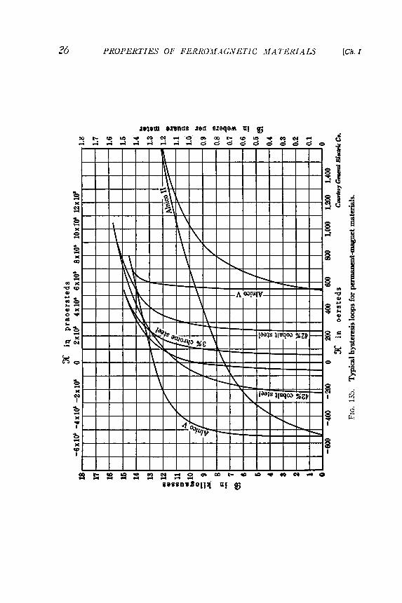
1Sb sho , vs hysteresis loops for some of the typical permanent - magnet
materials . The chief purpose in presenting the curves of various materials
on the same sheet and to the same scale is to facilitate comparison of
the magnetic properties among these materials .
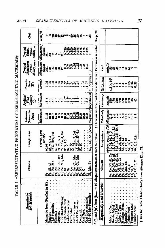
Representative properties for a selected group of magnetic materials
are given in Table I . These figures represent an average of values for
the various materials given by several sources . 12 In this table , the magnetically
soft materials are arranged in order according to their maximum
permeabilities , the material having highest permeability appearing at
the top . This order is also essentially that of decreasing relative magnetic
softness , a magnetically soft material having a relatively narrow hyster -
esis loop and hence a small coercivity , usually less than about 3 oersteds .
Magnetically soft materials are used in devices ' \vhere high permeabilities
are desired , and where the materials are subjected to alternating fields .
Magnetically hard materials are used for permanent magnets ; their uses
are discussed inChIV .
12 V . E . Legg , II Survey of Magnetic Materials and Applications in the Telephone System , "
BiS . T J . , 18 ( 1939 ) , 438 - 464 .

Mag
netiz
ing
FIG. l
Sa. N
orm
al
d-c m
agne
tizat
ion
curv
es
for va
rious
m
agne
tic
mat
eria
ls.
~!SU~ UI
25CHARAC1'ERI.':>'1'1~'.':>' OF MAGNE1'[ C MA1' ERl..1LSArt. 1]
l ~ dUl ~l ~nbS J~d S.taq~M. U! JG urf - 93 = [}<>t..>-..~~~]~~~~~()C,)
""M~ ....9;"J"J "J N
forc
e X
in
pra
oers
teds
Mag
netiz
ing
forc
e X
in
oer
sted
s
~ ~ ~ ~ <=) m ro t - ( 0 1/ ) - 1' M e- 1 . . . . <=) m ro t -e - 1 . . . . . . . . . . . . . . . . . . . . . . . . . . . . . . . . . . . . . . . .
sassn~201!){ U! JG 11 - ~ = f1 f4 !suap xnlJ
to ~ ..,. M ~ .... O
OC ) OOt - CDO ! ) " " " ' ~, . , j - , - , - , - , - , - , - , - ,
. . . . < = >
~ ~
li !SUdP xnlJ ~!SU!.1iUI
C) CX) t - to Ln . . , . C? c. t . . . .' - ; ' - ; ' - ; " , ; d ' - ; " , ; " , ; " , ; " "
f\ )
0. .
PRO PER TIE S' OF FERROMAG1VET1C ./}[ Al ' E R I ALS ~ ~F
IG. i S
b.
27Art. 4] CHARACTERISTIC,S' OF MAGNETIC MATERIALS
TA
BLE
I - RE
PR
ES
EN
TA
TIV
E
PR
OP
ER
TIE
S
OF
F
ER
RO
MA
GN
ET
IC

;:8 PROPERTIES OF FERROM.t1GJ.VETIC MATERIALS [Ch. l
The characteristics tabulated for the magnetically soft materials are:the maximum intrinsic flux density {3max, the residual flux density illr ,the coercive force Xc (also the retentivity and the coercivity respectivelysince the symmetrical cyclic magnetization was carried to saturation ,except as noted) , the maximum and initial permeabilities J.Lmax and J.Li,and the cost of the ra \v material . The characteristics tabulated for the
magnetically hard materials are the retentivity , the coercivity , themaximum value of the product of ill and X occurring bet\veen the pointsX = 0 and X = - Xc , and the cost. The product (ffiX )ma.z: is a measureof the effectiveness of the material for use in permanent magnets ; its
significance is discussed inChIV . The composition of the alloys in partsper hundred is given for both hard and soft materials . Inadvertent im -purities are not indicated , although they frequently produce seriouseffects . Almost all the materials mentioned in the table are commerciallyavailable, but a few are in the stage of laboratory development.
The extent of the dependence of certain of the magnetic propertiesof all ferro magnetic materials on the heat treatment to which they aresubjected cannot be overemphasized. A discussion of the heat-treatmentprocedure13 is beyond the scope of this textbook , but the importance ofthe treatment may be illustrated by the fact that Hipernik and Conpernik,although having the same composition, display \videly different magneticproperties. The differences are brought about wholly by a difference inthe heat treatment to which each material is subjected . The Perminvarsmaintain a practically constant permeability J.Li if not magnetized aboveabout 1,000 gausses. Magnetization above this value destroys the property
of constant permeability and this can be restored only by furtherheat treatment . Of the characteristics tabulated , the maximum intrinsic
flux density is the one subject to the least variation . It is dependentchiefly on the percentage of ferro magnetic material present in the alloy .The degree to which the other characteristics are subject to variationincreases in the order , residual inducti ' Jn, coercive force , and permeability
.
From the curves of ~igs. I3a and I Sh and the data of Table I , thematerial best suited from the magnetic point of view for any specificpurpose can be chosen. Whether the material should be used depends,of course, on numerous other factors such as availability , cost, mechanical
strength, and machinability . Characteristics of magnetic materialssubjected to alternating fields are given in Ch. V . Additional magneticdata on commercial materials may be obtained from the manufacturersor from the literature .
13 CE . Webb , " Recent Developments in Magnetic Materials ," I .E .E .J ., 82 ( 1938),303 - 323 .

Art. 5J MAGNETIC TRSTING 29
5. MAGNETIC TESTING
The normal magnetization curve and a family of hysteresis loops for a magnetic material give the information necessary for the solution of problems involving the use of the material in direct-current applications. In order to get these curves experimentally, some kind of permeameter� 4 is required in which a sample of the material can be tested.
Of the many types of permeameter, only those most commonly used will be described here. These are the Fahy simplex permeameter, which
Courtesy Mr. Frank P. Faky.
FIG. 16a. The Fahy simplex permeameter.
gives good precision up to magnetizing forces of 300 oersteds, and with an adapter up to 1,000 oersteds, and the /zigh- K permeameter, which permits a range up to 5,000 oersteds.
The Fahy simplex permeameter is pictured in Fig. 16a and is repre-sented diagrammatically in relation to its associated equipment in Fig. 16b. The circuit shown is somewhat simpler than the actual laboratory layout, since the object of this treatment is to set forth the method of testing rather than to stress the technique of manipulation. The ballistic galvanometer is first calibrated by the adjustment of its resistances R 8 , R , and RH, so that a change of some convenient unit of flux density in coil B (called the Es-coil) or a change of some definite unit of field
14 R. L. Sanford, �Magnetic Testing,� Cire. Nat. Bur. Stand. C415 (1937).

intensity in coil H (called the X -coil) produces a galvanometer deflection of one main scale division . This calibration requires the use of a
standard mutual inductor not sho\vn in the diagram.The specimenS to be tested is clamped bet\\'een the solid iron posts
P and the ends of the laminated iron yoke Y, forming a magnetic circuitin which flux is set up by the magnet()illotive force of coil ..11. The currentin this magnetizing winding is supplied from a steady direct -currentsource and can be a Jjusteu oy the variable resistor l ~.if . The s\\.itch S2
�
is closed when the normal magnetization curve is being taken and theswitch Sl serves to reverse the direction of the current in the coil. Thecoil H is an air-core solenoid of many turns of fine wire that provides ameans for measuring the difference in magnetic potential between theposts P . This difference in magnetic potential divided by the distancebetween posts l.s the magnetizing force JC in the specimen.
Before data for the normal ill (JC) curve are taken, the sample is de-magnetized, and, with s\\'itch S2 closed, rheostat RM is set for the lowestpoint on the curve. S\\.itch Sl is placed in either closed position andS3 is left open. The current in coil J.1I is reversed several times by meansof s\vitch Sl in order to put the sample in cyclically magnetized conditionS
\\itch S3 is no\, closed in the lo\\"er position and Sl is moved from
one pair of contacts to the other . The deflection of the ballistic galvanometer then indicates the change in flux density 03 in the sample. A
repetition of the process with S3 in the upper position , using the samevalue of magnetizing current as before, gives the corresponding change inmagnetizing force JC in the sample. Other points on the curve can beobtained through increasing the current in coil AI , putting the sample incyclic condition by several reversals of Sl , and then taking data as for
30 PRO P Ej~TIE.s' OF FER1{O.~l .11 (;1\' f~l 'I L' .J~fAT ERI A J..S' [Ch.I
FIG. 16b.R .lf
Diagram of connections for J"ahypermeameter .
Rr

ill
ffi ",or - - - - - - - - - - - - - - - - - - - -
fII4Z x
,/"
/ "/ .."/ "
. , /
-=::::~~::~-----_.._......,........,
Art. 5] MAGNETIC TESTING 31
the first point . The normal magnetization curve is the locus of point ~plotted from these data as indicated by the broken line in Fig . 17.
When a hysteresis loop is to be determined, the cyclic condition isfirst established at the desired value of ffimax. The rheostat RT is set to
FIG. 17. Points on hysteresis and normal magnetization curves obtained with permeameter
give a small decrease in the reading of ammeter A when S2 is opened .With S3 in the lower position , S2 is opened and the galvanometer de~flection is noted. The reading indicates the change in 93 as it is decreasedfrom 93max. This will give the value 93max - 93' as indicated in Fig . 17.The cyclic condition at the tip of the loop is no\v restored through reversingS
], closing S2, and then reversing Sl again. If , \vith S3 in the upperposition , S2 is again opened, the value Xmax - X ' is obtained. Pointsfarther do \vn the loop can be obtained in the same way by the use of

32 [Ch. IPROPERTIES OF FERROMAGNETIC MATERIALS
larger values of resistance RT, each reading being made from a cyclicalcondition at the tip of the loop. This makes it possible to establish identical
initial conditions for the ill and X readings and also to avoid cumulative errors which would accrue ingoing from point to point .
When the points on the hysteresis loop are near the horizontal (X )axis , small errors in the determination of ill are not of much consequence ,
because the curve is nearly vertical , but errors in X are of importance .The method just described for the determination of X is likely to introduce
a considerable error in this region , since the values of X are found
through taking the difference between Xmax and another large valueX maz - X determined from the test . Greater precision in these valuesof X is obtained by the use of an attachment which makes possible themeasurement of X directly at a fIXed magnetization of the specimenthrough quickly rotating the coil H 180 degrees. Not only is greater
precision possible in a singlereading by the use of thisdevice , but several readingsof X can be taken without
~ changing the magnetic con-..'?; dition of the specimen ..~ Since a considerable differ-
~
.~ ence in magnetic potential~ exists bet\veen the ends ofS
the test bar , a leakage offlux a \vay from the bar
0 distance from center of test bar through the surrounding airis bound to occur . For this
reason, the flux density deFIG. 18. Distribution of magnetizing force X along creases alon (J" the bar from
test bar for : (a) coil on yoke , (b) coil surrounding the d t b d th. ( ) b . . f ( ) d (b) en s owar e cen -
speCImen, C Corn Inat Ion 0 ,a an . . h .ter WIt a correspondIngdecrease in magnetizing force as sho\vn in curve (a) of Fig . 18.The greater the total applied magneto motive force , the greater will bethis leakage and resulting nonuniformity in X along the specimen. Formagnetizing forces greater than 300 oersteds , this effect becomes greatenough to interfere \vith the precision of the instrument . The recognitionof this situation and the need for testing the ne\v hard permanent -magnetalloys led to the development of the super -X adapter . This device isclamped against the yoke Y in place of the sample and auxiliary postsP and holds near its center a short length of test material and an accompanying
short X -coil . Magnetizing forces up to 2,500 oersteds can be
applied to the sample without overheating the apparatus , but the precision of the measurements above about 1,000 oersteds is doubtful .

Art. 5) MAGNETIC TESTING 33
The curve (b) of Fig. 18 shows the variation of magnetizing force along a specimen when the magnetizing coil is a solenoid surrounding the specimen rather than a winding on the yoke. Here the value of JC is greatest near the center and drops off toward the end. Curve (c) repre-sents a combination of these two curves and indicates that, with a part of the magnetizing winding on the yoke and a part surrounding the specimen, a uniform field can be obtained over a considerable length about the center of the test bar. This principle is used in the Babbitt� 5 permeameter, which gives good precisior up to 1,000 oersteds.
The most recent development is the Sanford-Bennett� 6 � 7 high-�JC permeameter of the U. S. Bureau of Standards. This in-
strument is claimed to measure
both E and 3C in small samples (up to cross-sectional dimensions 0.75 in. X 1.5 in.) for magnetiz-ing forces up to 5,000 oersteds with an error not exceeding 1 per cent. Values of K up to 9,000 oersteds can be used with-out overheating the instrument or the sample, but the precision for the higher values has not yet been determined. Figure 19
courlesy ivat onal Bureau of Standards. shows this permeameter. The two large coils in the center FIG. 19. The Sanford-Bennett high-X per-
meameter. surround the pole pieces and comprise the main magnetizing winding. Each of these coils has 2,690 turns of 14 AWG silk-enamel wire. Each of the auxiliary or yoke coils has 1,600 turns. Several 3-coils are available in order that one may be chosen which fits snugly around the sample to be tested. Each of these coils has 25 turns of fine wire wound on a thin brass shell. This is clearly visible at the middle of the picture, as is also the JC-coil just beneath the E1 -coil. The device at the front is a motor-driven rotator for the 3C-coil, in order that JC may be measured at a fixed magnetization
� B. J. Babbitt, �An Improved Permeameter for Testing Magnet Steel,� J.O.S.A. and R.S.I., 17 (1928), 47�58.
� 6 R. L. Sanford and E. G. Bennett, �An Apparatus for Magnetic Testing at High Mag-netizing Forces,� J. Res. Nat. Bur. Stand., 10 (1933),. 567�573.
17 R. L. Sanford and E. G. Bennett, �An Apparatus for Magnetic Testing at Magnetizing Forces up to 5.000 Oersteds,� J. Res. Nat. Bur. Stand., 23(1939), 415�425.

34 [Ch.IPROPERTIES OF FER R Olrf A G NE TIC MATERIALS
of the specimen . The instrument connections are essentially the same asfor the Fahysimplexpermeameter .
6 . ENGINEERING UTILIZATION OF FERROMAGNETIC MATERIALS
A detailed study of the data of Figs . I Sa and I Sb and 'l 'able I showsthat the various alloys mentioned display the characteristics typical offerro magnetic materials to markedly varying degrees. The predominanceof certain characteristics determines the use fulness of aparticularmate -rial for a specific purpose. For example, for an electromagnet, a materialthat has a relatively large permeability and a large saturation fluxdensity is usually desirable in order that the magneto motive force andthe volume of material required shall be small . But these properties mustnot be achieved at too great a sacrifice of the desirable mechanical
properties, or at too large a cost. A relatively pure iron or low-silicon-content sheet steel is frequently used for such purposes. However, whenthe flux is varying with time, as it does in transformers, reactors, androtating machines, energy is dissipated in the iron in a manner explainedin Ch . V . Because of heating , and for economic reasons, this dissipationof energy must be small . Electrical - sheet steel with between 2 and 4
per cent silicon is used frequently in such devices. Its cost per pound isrelatively small and it is commercially available in many forms convenient
for fabrication into desired shapes. Some of these forms are illustrated in Fig . 12. Because of its silicon content , it has relatively high
resistivity and a hysteresis loop of relatively small area,* wllich reducethe energy loss in an alternating field. \Vhen more than about 4 per centof silicon is used, the improvement in the magnetic properties is negligible,and the material becomes brittle and difficult to punch into desiredshapes. Manufacturing difficulties are then increased .
In some communications equipment , a material having an extremelyhigh permeability is desirable . For such applications , certain nickel -ironalloys, known as Permalloys18 , 19 (permeability alloy) or Hipernik in theUnited States , or a nickel -iron -copper alloy , known as Mumeta12 O anddeveloped in England , may be used . The use of these alloys involves anincreased cost per pound of material but not of cost per unit of inductance .
. Representative values of core loss for symmetrical cyclic magnetization and representative values of resistivity for average samples of various materials are tabulated in
Art . 3 , Ch . V .
18 G. \V. Elmen , " Magnetic Alloys of Iron , Nickel , and Cobalt ," A .JE.E . Trans ., 51( 1935) , 1292- 1299.
19 V . E . Legg and F . J . Given , " Compressed Powdered Molybdenum Permalloy for High -Quality Inductance Coils ," BiS .T .J ., 19 ( 1940) , 385- 406 .
20 W . F . Randall , " Nickel -Iron Alloys of High Permeability with Special Reference toMumetal ," J .E .E .J ., 80 ( 1937) , 647.

35Art. 6] UTIliZATION OF FERROMAGNETIC MATERIALS
The large permeability of these alloys is chiefly the result of their havingbeen subjected to a particular heat-treatment procedure, for ,vhichcareful control is necessary. Also, their permeability is very susceptibleto strains introduced by mechanical ,vorking ; hence their use may increasemanufacturing problems.
In Ch. V an analysis is presented sho,ving that eddy-current loss canbe reduced through building ferromagnetic of laminated sheetsinsulated from each other by their surfacelacquer . Another method of reducing eddy
cores
oxides or by an insulatingcurrents is to reduce the
material to a powder and then to insulate the particles from one anotherby an insulating substance tough enough to withstand the forces of com-pression when the powder is molded into the cores of various shapes.Figure 20 is indicative of the advance given to this art by the engineersand physicists of the Bell System during the past 20 years.
In certain other communications problems, extreme constancy ofpermeability throughout the working range is imperative . A nickel-iron-cobalt alloy known as Perminvar (permeability invariable ) and a nickel-iron alloy known as Conpernik possess this property at relatively lowflux densities. Unfortunately , the permeability of these alloys is low.They have the unique properties of negligible residual magnetism andof negligible coercive force throughout their useful range. Perminvarhas a low resistivity , of the order of 20 microhm-centimeters, but by theaddition of about 7 per cent of molybdenum its resistivity is increasedby a factor of about four ,vithout appreciable sacrifice of its magneticproperties.
' Vhen a material is to be used in rotating machinery, one having prop -erties different from the above is required. Mechanical strength becomes
important , since in the rotors of turbo-alternators , centrifugal forces

36 PROPERTIES OF FERROMAGNETICMATERIALS [Ch. I
are often large and a material with large tensile strength is then essential.\Vhen the magnetizing forces are essentially constant , solid steel forgingsof nickel stcel or nickel -chromium steel are often used. These alloys possess
the high values of saturation flux density desired in steels for these
applications . In the parts of the machine where the flux is alternating , asit is in the neighborhood of the alternating -current windings , the resulting
energy losses are of considerable concern . For these parts , asuitable silicon steel is used .
In rotating -armature machines , a special problem arises. The fluxdensity in the teeth is large , and a material with a very large saturationflux density is desired in order that a large flux per pole shall be availablewithout uneconomical values of excitation in spite of the constriction atthe roots of the teeth .
An iron-cobalt alloy called Permendur (permeability enduring) mayhold interesting possibilities for these ~tpplications , although it has notyet been usc.~d to any extent for them . 1'he present lligh cost vf this alloy ,its brittleness , and its lo,v resistivity are deterrents to ,vicile use. Theaddition of about 1.7 per cent of vanac.lium , ho" .ever , decreases the brittleness
, and increases the resistivity to about 24 microhmcentimeters . Atpresent, Permendur is used only in small electromagnets, relays, or telephone
equipment . In certain applications such as in aeronautical orother equipment ,vhere space or " .cight is at a premium , the item of itscost should not be a serious one. The important factors are the relationbetween the cost per pound of the material , the cost per pound of thefinished article , and the percC':!1tage by ,,"cight of the material in thefinished article .
When ferro magnetic materials are used as permanent magnets , otherproperties become primary in importance. Permanent-magnet applications
usually arc in instruments , meters, and small motors or generators,where the cost per pound of the finished product is relatively large . Themagnets are subject frequently to severe mechanical shock , to alternatingfields , and to moderate changes in temperature . The mechanical strengthof the magnets is usually consider ably in excess of that necessary . Thecoercivity and retentivity of the matel -ial become , in a general ,vay , thefigures of merit . For many applications , the determining factor is themaximum value of the product (ill ' X) along the demagnetization curvebetween ' X equals 0 and ' X equals ' Xc as is explained inChIV . Thisproduct is tabulated as (ill ' X)max in Table I for those materials that aresuitable for use as permc ,nent magnets .
During the early days of the electrical industry , the carbon steels usedfor permanent magnets ,,'ere seriously ,veakened magnetically by vibration
, alternating fields , and temperature variations , and ,vere thereforeof little use where constancy of field ,vas desired. The development of

37Art. 6] UTILIZATION OF FERRO..' f ",l G NE TIC -,V.tl TE R I ALS
tungsten-steel and chromium-steel alloys provided improved permanent -magnet materials which still find wide application where the cost of thematerial is of major importance and space is not . 1'hcse steels are subjectto the same kind of defects as carbon steel but to a lesser degree.
The deveiopmellt of cobalt steel provided a materi ::tl superior magnetically to either tungsten or chromium steel. Not only can stronger
fields be produced by a cobalt-steel magnet, but ::tlternating fields andmechanical vibration have relatively little effect on its permanency.Recently has come the development of other alloys containing chieflyiron , nickel , cobalt, and aluminum . Thcse alloys, "\vhich are kno"\vn bythe trade n::tme Alnico in the United States ancl Nipermag in England ,are less expensive to procluce and lighter in wei,~ht than cob::Tit steel, andyet have better magnetic properties. rl'he alloy Alnico21 is produced"\\"ith various compositions, an average composition being about 20 percent nickel , 12 per cent ::tluminum , 5 per cent c()l)~Tit, 0.4 per cent manganese
plus silicon, and the remainder iron . It h;L3 a l ::trge (ill X )max andits properties are changccl only slightly by vibr ::ttion, altcrnating fields,or even a surprisingly "\\'ide range of temperature v::triation . The use ofthis alloy introduces a ne"\v problem, ho\\"ever, for it cannot be machinedreadily and frequently must be cast in the form in which it is to be used.Hence use of it may involve a complicated manufacturing problem. Thisproblem has been partly solved by sintering ,22 a process in which thepo\\'"dered constituents are diffused togr:-ther at high temperature andunder tremendous pressure. Some of the parts formed with considerableaccuracy by this process are sho\vn in Fig . 21. Larger elements, as wellas the ones sho\vn, are commercially av::til~Lble ancl f:::tn be combined "\vithsoft iron or steel in the construction of magnetic devices.
Certain other alloys, and also the oxides of iron and iron-cobalt , showdesirable properties as permanent magnets. rrhe oxide magnets must bemolded and are relatively brittle . Future developments in this part ofthe art may yield useful products . In many devices, no single ferro-magnetic material is adequate. For example, the modern telephone receiver
sho\\'"n in Fig . 22 has Remalloy permanent magnets, 45-Permalloypole pieces, and a Permendur diaphragm.
In certain devices, such as relays, resistors, and transformers, a materialhaving magnetic properties very sensitive to tcmperature can be used toadvantage. This conclition has only recently become of ~ngineeringimportance, although the change in the magnetic property with temperature
has been of theoretical significance since the era of early attemptsto forrnul::tte a theory of ferro magnetism. By appropriate composition,an alloy is obtained having the temperature at which it ceases to be ferro-
21 J. Q. i\ dams, II i\1nico - Its Properties and Possibilities," GiE. Re-ol., 41 (1938),518-523.22 G. H. I Iowe, II Sintcring of Alnico," Iro'~ Age, 145 (1940), 27.

38 PROPERTIES OF FERROMAGNETIC MATERIALS [ C / i!
Courtesy General Electric Co.
Fxo. 21. Representative collection of small Alnico magnets. Paper clip included to indicate size.
� diaphragm air gaps polarizing ______ magnets
olepi Courtesy Bell Telephone Laboratories.
Fio. 22. Magnetic circuit of telephone receiver.

39Art. 6] U T I' ll Z A T I ON OF FERROMAGNETIC MATERIALS
magnetic (that is, its Curie point ) in a useful range for many engineeringapplications . Alloys having this property are used for the temperature-sensitive element in temperature -sensitive reactors , contactors , and
transformers. The possibilities for useful application of alloysof this kindmay be better appreciated when it is realized that an alloy23 comprisingapproximately 35 per cent nickel , 5 per cent chromium, 60 per cent iron ,and 0.3 per cent silicon, appropriately heat-treated, has a saturationflux density of about 6,000 gausses at a temperature of 60 degrees centigrade
but is essentially nonmagnetic at 160 degreest \ nother of thesealloys , 12.5- 80 i\ Io -Permalloy , becomes nonmagnetic at 40 degreescentigrade , or slightly above normal room temperature .
The magnetic properties of many ferro magnetic materials changegradually with time , a phenomenon known as aging . All the steels behavethis \yay to some extent since their iron-carbon compounds are not stable,but change from one form to another \yith time . The changes may proceedrapidly at high temperatures, but appropriate sudden cooling as part ofthe heat treatment can so retard the rate that the whole effect is distributed
over a period of years. I Iowever, the aging cannot be completelystopped . The silicon steels sho\v only a slight aging effect because of thereaction occurring among the silicon , oxygen , and carbon during theirproduction .
While the effects of aging on the magnetic properties of all steels areimportant , usually causing a decrease in the permeability and an increasein coercivity of magnetically soft materials, the effects are especiallyserious when they occur in magnetically hard steels used for magnets ininstruments and meters . Here the strength of the magnet is decreased ,
and the accuracy of the device is impaired by even a very small changein the strength . The use fulness of the magnetically hard carbon steelscan be increased by artificial aging. For example, if the steel is subjectedto a temperature of about 100 degrees centigrade for several hours , arapid aging and considerable change in strength occur . The subsequentrate of change of magnetic strength at normal room temperature is thengreatly reduced.
i\ Iany of the newer alloys do not contain carbon in significant amountsand are not subject to these aging effects . Some of the compounds formed ,notably Alnico , are stable even up to temperatures above 600 degreescentigrade. Welding is even possible with some of these alloys after theyhave been heat-treated, without appreciably impairing their desiredmagnetic properties. The advantages offered by such alloys for manufacturing
process es may therefore be readily appreciated.
23 L . R . Jackson and H . W . Russell , " Temperature -Sensitive Magnetic Alloys and TheirUses," lnstrume ' tts, 11 ( 1938), 280- 282.

appeared in the periodical literature in the fields ofsince this textbook was published.
Plot, on the same horizon ta J axis, a complete cycle of sinusoidal voltage and thecorresponding cycles of flux density and magnetizing force. Use a horizontal scale of40 degrees = 1 in . Use vertical scales of 1,000 v = 1 in ., 0.40 weber per sq m = 1 in.,and 1,000 praoersteds = 1 in. The waveform of J( is similar to that of the magnetizingcurrent of the transformer described in Ch. VI .
40 ICh. r
ill in webers/ sq m X in praoersteds
- 1 .00 - 3 ,750
- 0 .92 - 1 ,500- 0 .77 0
- 0 .50 + 1,400- 0 .20 + 2,100
0 .00 + 2 ,350+ 0 .45 + 2,500+ 0 .75 + 2 ,950+ 1.00 + 3 ,750
24 See " Magnetic Delay." GiE. Re'V.. 45 (1942), 245, 246,
PROPERTIES OF FER R O11f A G NE TIC MATERIALS
PROBLEMS
1 . Describe briefly any new developments in the theory of magnetism which have
physics and electrical engineering
2. Give the physical properties including characteristic curves of any importantferro magnetic materials not included in this chapter.
3. A strip of specially treated stainless steel (18% chromium, 8% nicke]), whenfirst placed under a powerful permanent magnet. shows very little tendencv to belifted , but , after the lapse of about one and one-half minutes, is strongly attractedto the poles of the ma[':n~t . The special treatment consists in removing the nitrogenfrom the metal and quenching in water from a temperature of 1,100 F. The magneticexperiment is performed immediately after quenching. I Io\v can this change in magnetic
properties be explC1.ined? Does your explanation indicate that the strip regainsits nonferromagnetic properties when removed from the magnetic field ?24
4. When a sinusoidal voltage of 2,300 v effective value is applied at the primaryterminals of a transformer, the maximum flux density in the core is 1 \veber per sq m.The data for the hysteresis loop of the steel in the transformer core are given in thefollowing table: