Embed Size (px)
Citation preview
Prompt Kicker
M. Aoki
2
3
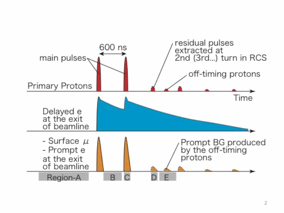
H-Line Kicker• Prompt Burst: 5e8 / 200-ns @ H-line exit
– Any detectors will be saturated.• Need to reduce the prompt burst by kicker.
Mag. Field > 385 Gauss
Gap 320 mm
Width 320 mm
Length 400 mm
No. 4
Fall Time < 300 nsec
Rep. Rate 25Hz
Electric Noise Minimum
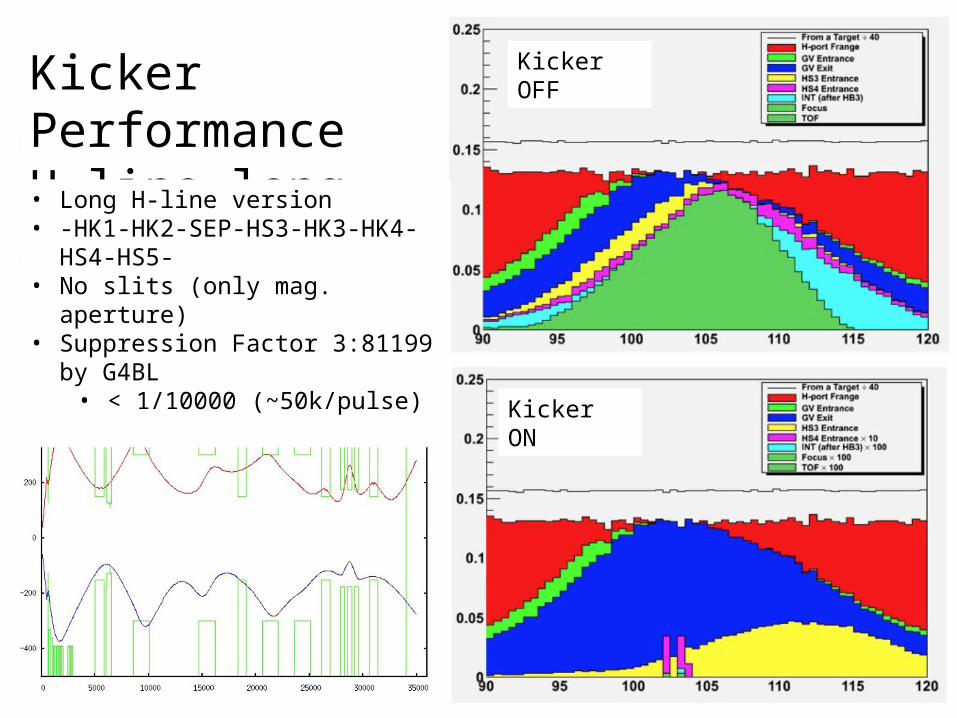
Kicker PerformanceH-line long• Long H-line version• -HK1-HK2-SEP-HS3-HK3-HK4-HS4-HS5-• No slits (only mag. aperture)• Suppression Factor 3:81199 by G4BL
• < 1/10000 (~50k/pulse)
Kicker OFF
Kicker ON
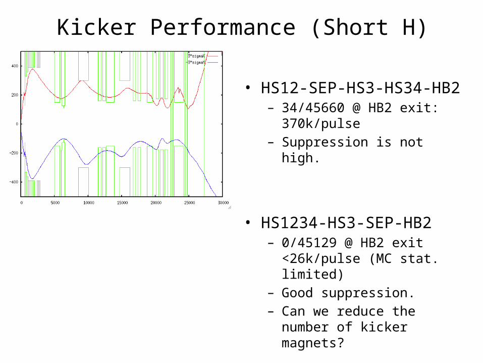
Kicker Performance (Short H)
• HS12-SEP-HS3-HS34-HB2– 34/45660 @ HB2 exit: 370k/pulse– Suppression is not high.
• HS1234-HS3-SEP-HB2– 0/45129 @ HB2 exit
<26k/pulse (MC stat. limited)– Good suppression.– Can we reduce the number of
kicker magnets?
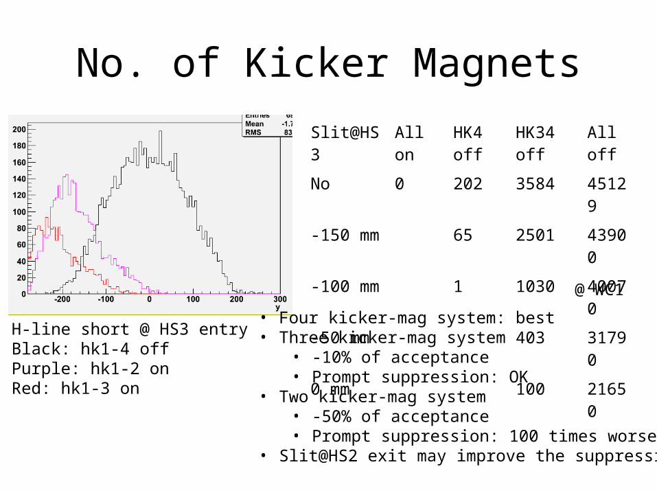
No. of Kicker MagnetsSlit@HS3 All on HK4 off HK34 off All off
No 0 202 3584 45129
-150 mm 65 2501 43900
-100 mm 1 1030 40070
-50 mm 403 31790
0 mm 100 21650
H-line short @ HS3 entryBlack: hk1-4 offPurple: hk1-2 onRed: hk1-3 on
@ WC1
• Four kicker-mag system: best• Three kicker-mag system
• -10% of acceptance• Prompt suppression: OK
• Two kicker-mag system• -50% of acceptance• Prompt suppression: 100 times worse
• Slit@HS2 exit may improve the suppression.
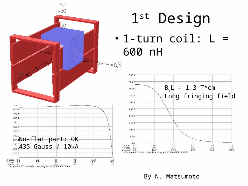
1st Design
No-flat part: OK435 Gauss / 10kA
ByL = 1.3 T*cmLong fringing field
By N. Matsumoto
• 1-turn coil: L = 600 nH
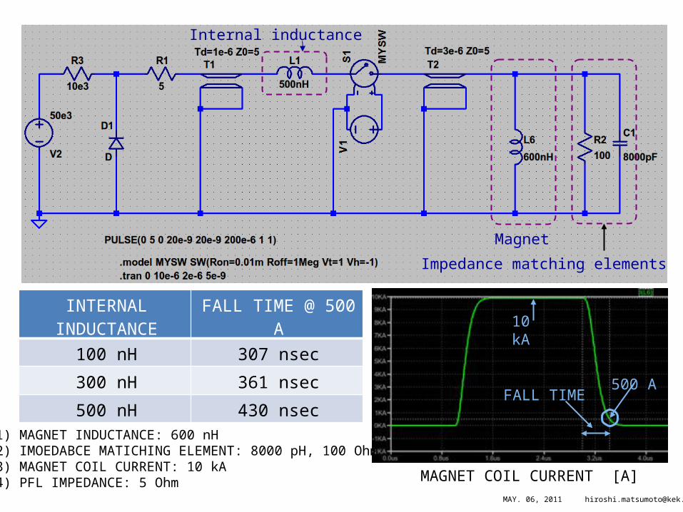
Magnet
Impedance matching elements
Internal inductance
INTERNAL INDUCTANCE
FALL TIME @ 500 A
100 nH 307 nsec
300 nH 361 nsec
500 nH 430 nsec
500 A
10 kA
FALL TIME
MAGNET COIL CURRENT [A]
1) MAGNET INDUCTANCE: 600 nH2) IMOEDABCE MATICHING ELEMENT: 8000 pH, 100 Ohm3) MAGNET COIL CURRENT: 10 kA4) PFL IMPEDANCE: 5 Ohm
MAY. 06, 2011 [email protected]
9
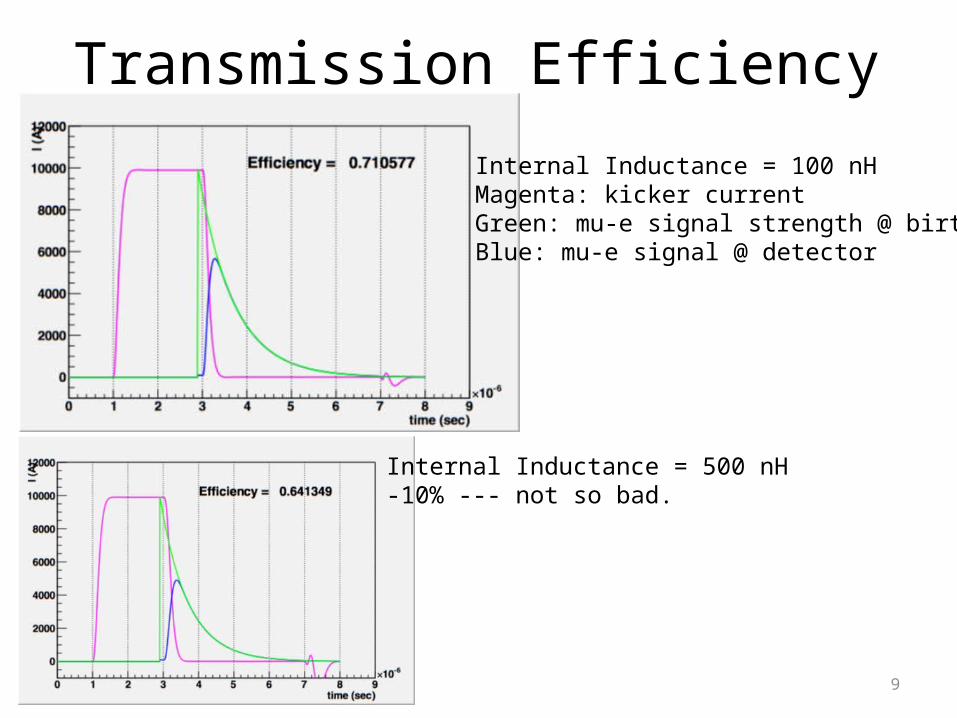
Transmission Efficiency
Internal Inductance = 100 nHMagenta: kicker currentGreen: mu-e signal strength @ birthBlue: mu-e signal @ detector
Internal Inductance = 500 nH-10% --- not so bad.
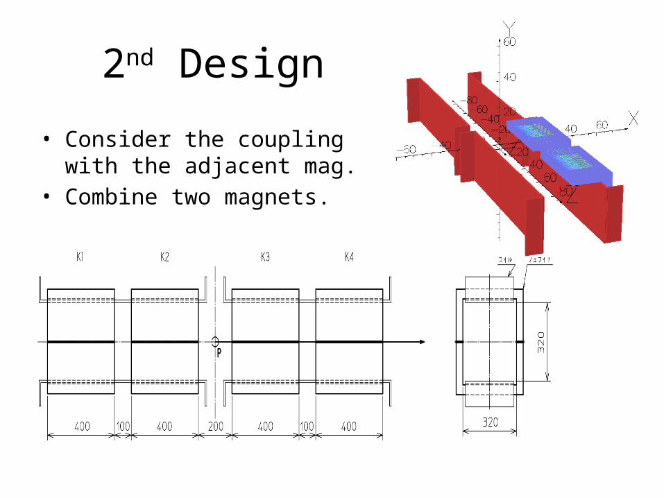
2nd Design
• Consider the coupling with the adjacent mag.
• Combine two magnets.
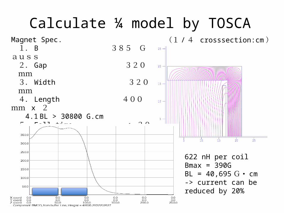
Magnet Spec. 1. B 385 Gauss 2. Gap 320 mm 3. Width 320 mm 4. Length 400 mm x 2
4.1 BL > 30800 G.cm 5. Fall time < 300 nsec 6. Coil 6.1 No. of turns 1 T 6.2 Current 10,300 A
(1 / 4 crosssection:cm )
Calculate ¼ model by TOSCA
622 nH per coilBmax = 390GBL = 40,695G・ cm-> current can be reduced by 20%
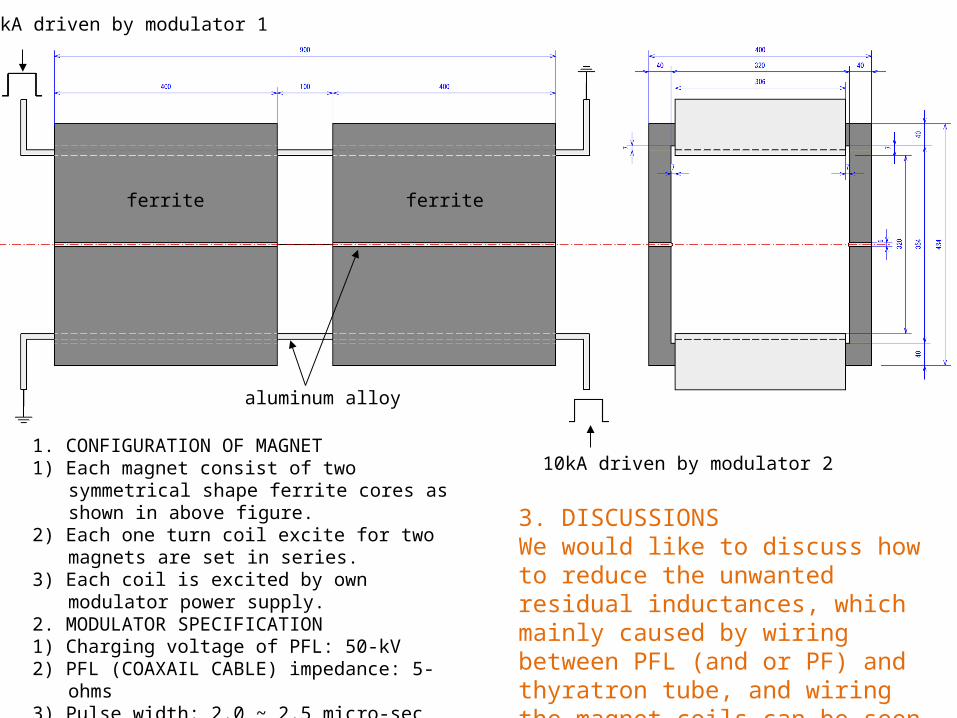
10kA driven by modulator 1
10kA driven by modulator 2
aluminum alloy
ferrite ferrite
1. CONFIGURATION OF MAGNET1) Each magnet consist of two symmetrical shape
ferrite cores as shown in above figure. 2) Each one turn coil excite for two magnets are
set in series.3) Each coil is excited by own modulator power
supply.2. MODULATOR SPECIFICATION1) Charging voltage of PFL: 50-kV2) PFL (COAXAIL CABLE) impedance: 5-ohms3) Pulse width: 2.0 ~ 2.5 micro-sec4) Load: short terminated inductor (622-nH)
3. DISCUSSIONSWe would like to discuss how to reduce the unwanted residual inductances, which mainly caused by wiring between PFL (and or PF) and thyratron tube, and wiring the magnet coils can be seen in page 2-3.
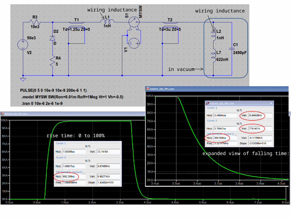
rise time: 0 to 100%
wiring inductance wiring inductance
in vacuum
expanded view of falling time:
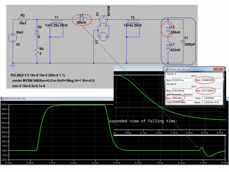
expanded view of falling time:
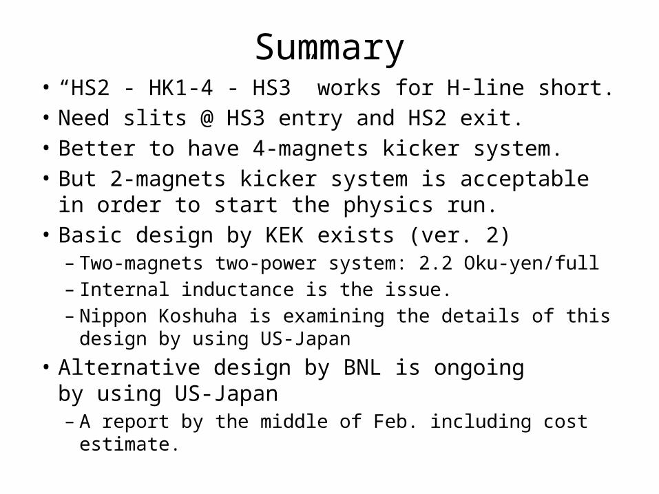
Summary• “HS2 - HK1-4 - HS3” works for H-line short.• Need slits @ HS3 entry and HS2 exit.• Better to have 4-magnets kicker system.• But 2-magnets kicker system is acceptable in order to
start the physics run.• Basic design by KEK exists (ver. 2)
– Two-magnets two-power system: 2.2 Oku-yen/full– Internal inductance is the issue.– Nippon Koshuha is examining the details of this design by
using US-Japan• Alternative design by BNL is ongoing
by using US-Japan– A report by the middle of Feb. including cost estimate.