Embed Size (px)
Citation preview
712/08/2008 - Sigma/ 1
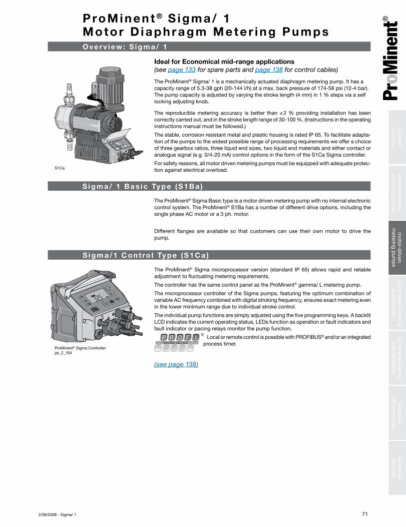
S1Ca
The ProMinent® Sigma microprocessor version (standard IP 65) allows rapid and reliable adjustment to fluctuating metering requirements.
The controller has the same control panel as the ProMinent® gamma/ L metering pump.
The microprocessor controller of the Sigma pumps, featuring the optimum combination of variable AC frequency combined with digital stroking frequency, ensures exact metering even in the lower minimum range due to individual stroke control.
The individual pump functions are simply adjusted using the five programming keys. A backlit LCD indicates the current operating status, LEDs function as operation or fault indicators and fault indicator or pacing relays monitor the pump function.
Local or remote control is possible with PROFIBUS® and/or an integrated process timer.
(see page 138)
ProMinent® Sigma Controller pk_2_104
ProMinent ® S igma/ 1 Motor D iaphragm Mete r ing Pumps
The ProMinent® Sigma Basic type is a motor driven metering pump with no internal electronic control system. The ProMinent® S1Ba has a number of different drive options, including the single phase AC motor or a 3 ph. motor.
Different flanges are available so that customers can use their own motor to drive the pump.
Overv iew : S igma/ 1
S igma/1 Cont ro l Type (S1Ca )
Ideal for Economical mid-range applications (see page 133 for spare parts and page 138 for control cables)
The ProMinent® Sigma/ 1 is a mechanically actuated diaphragm metering pump. It has a capacity range of 5.3-38 gph (20-144 l/h) at a max. back pressure of 174-58 psi (12-4 bar). Thepumpcapacityisadjustedbyvaryingthestrokelength(4mm)in1%stepsviaaselflocking adjusting knob.
The reproduciblemetering accuracy is better than±2%providing installationhasbeen correctlycarriedout,andinthestrokelengthrangeof30-100%.(Instructionsintheoperatinginstructions manual must be followed.)
The stable, corrosion resistant metal and plastic housing is rated IP 65. To facilitate adapta-tion of the pumps to the widest possible range of processing requirements we offer a choice of three gearbox ratios, three liquid end sizes, two liquid end materials and either contact or analogue signal (e.g. 0/4-20 mA) control options in the form of the S1Ca Sigma controller.
For safety reasons, all motor driven metering pumps must be equipped with adequate protec-tion against electrical overload.
S igma/ 1 Bas ic Type (S1B a )
analyticalsensors
analyticalinstrum
entationp
ump
engineeringsp
ecificationsp
ump
spare p
arts &accessories
motor-d
rivenm
etering pum
ps
solenoid-d
rivenm
etering pum
ps
prod
uctoverview

72 2/08/2008 - Sigma/ 1
Standard Modes and Func t ions
Feed rate is determined by stroke length and stroke rate. Stroke length is manually adjustable from 1to100%inincrementsof1%viathe stroke length knob.
Stroke rate can be set to a maxi-mum of 90, 170 or 200 strokes per minute (pump dependent). An illuminated LCD displays stroke length, stroke rate and an accumu-lative stroke counter, which can be cleared and reset.
Pump capacity output is displayed in either U.S. gph or l/h, set by the operator. Output is accumu-lated and totalized capacity is also displayed in either U.S. gallons or litres.
The “i” key is used to scroll in-formation screens for stroke rate, stroke length, stroke counter, ca-pacity and totalized capacity. Other information is available depending on control mode.
Control Modes trol ModesThe control modes available with the Sigma/1 include manual, external contact with pulse con-trol (multiplier/divider), batch, or analog control. The Profibus option includes all control modes, plus fieldbus connection.
In the “Manual” mode, stroke rate is controlled manually. The “Con-tact” external mode allows adjust-ments to be made externally (e.g. by means of a pulse-type water meter for proportional chemical feed). Pulse signals are fed into the contact input of the pump by an optional control cable. Each pulse from a water meter or pulse-type controller provides the pump an input to pump at the selected pulse ratio, up to the pump’s maximum stroke rate. Over-stroking the pump is not possible.
Standard Functions “Calibrate” The pump can be directly calibrat-ed in-line to actual flow. Calibra-tion is maintained within the stroke frequency range of 90/170/200 spm (model dependent). A warning indicator flashes when adjustments to the stroke volume are made outside the calibrated range of +/-10%.
“Auxiliary Frequency” An auxiliary frequency can be pro-grammed. This default stroking rate can be enabled via the optional control cable.
“Flow”The Sigma/1 series metering pumps will monitor their own output, with an optional adjustable flow monitor. Every fluid discharge is sensed and fed back to the elec-tronic control circuit of the pump. If insufficient fluid is discharged for a predetermined number of strokes (up to 125), the pump automati-cally stops and the red LED lights. The optional fault relay changes state to issue an alarm or activate a standby pump.Call for availability.
Ensure fluid fl“Float Switch”An optional two-stage ProMinent float switch can be plugged into the pump to monitor chemical tank levels. An early warning is issued when the allowable minimum level is reached. The pump contin-ues to operate while the display flashes, the yellow LED lights and an optional collective fault relay changes state to issue an alarm. If the liquid level in the supply tank drops another 3/4” (20 mm), the pump automatically shuts down, the LCD displays “Minim” and the red LED lights. The optional fault relay remains activated.
“Pause”The Sigma/1 series can be re-motely started and stopped via a dry contact through the optional control cable.
“Stop”The Sigma/1 can be stopped by pressing the STOP/START key without disconnecting from the power supply.
“Prime”Priming is activated by pressing both arrow keys at the same time while the frequency display is showing.
Function and Error Indicators xs
Three LED lights on the pump faceplate signal operational status. The green light flashes during normal operation, and the yellow light warns of a situation that could lead to a fault (e.g. low chemical). If a fault occurs “error” will appear on the LCD screen and the red LED light appears.
ProMinent ® S igma/ 1 Motor D iaphragm Mete r ing Pumps
sole
noid
-driv
enm
eter
ing
pum
ps
mot
or-d
riven
met
erin
g p
ump
sp
ump
sp
are
par
ts &
acce
ssor
ies
pum
p e
ngin
eerin
gsp
ecifi
catio
nsan
alyt
ical
inst
rum
enta
tion
anal
ytic
alse
nsor
sp
rod
uct
over
view
732/08/2008 - Sigma/ 1
ProMinent ® S igma/ 1 Motor D iaphragm Mete r ing PumpsOpt iona l Modes and Func t ions
Optional Control Modes
“Analog” Mode
With this option, the stroking rate of the Sigma/1 is directly proportional to the analog signal. For a custom range setting, the curve feature of the analog input can be selected. With this, the pump response to the analog input can be easily pro-grammed.
“Contact” Mode with Pulse Control
This feature is used to “tune” the pump to contact generators of any kind (e.g. pulse-type water meter or process controller), and elimi-nate the need for a costly external control unit. The following func-tions can be selected by means of the keypad.
Pulse step-up (multiply) and step-down (divide)
By simply entering a factor in the 0.01-99.99 range, the step-up or step-down ratio is set.
For example:
Step-up Factor:99.99 1 pulse = 99.99 pump strokes10 1 pulse = 10 pump strokes
Step-down Factor: 0.25 4 pulses = 1 pump stroke0.01 100 pulses = 1 pump stroke
“Batch” Mode
The Batch mode is a variation of the contact operating mode. A number of strokes can be predeter-mined up to 65,535 strokes (whole numbers) or the feed quantity can be predetermined. The batch is then initiated by either pressing the “P” key on the pump face or providing a contact to the external control cable.
Access Code
A programmable access code to prevent unauthorized changes to settings is available as an option.
Relay outputs. . .Fault annunciating relay
For low tank level (flow switch), loss of flow (flow monitor), loss of analog signal and diaphragm failure detector, system faults and fuse/power supply failure.
Fault annunciating and Pacing relay
In addition to the fault annunciating relay, a contact closure is issued with every pump stroke (contact duration 150 ms). This allows a second ProMinent metering pump to be paced synchronously, or to totalize flow with an external stroke counter.
4-20 mA Analog Output
A 4-20 mA analog output option is available for use with pumps that operate in the manual mode or by a remote 4-20 mA analog reference signal. The 4-20 mA analog output signal is linear to pump frequency multiplied by the percentage of stroke length. The output signal is isloated and can drive up to 300 Ohms impedance. Analog output can be used for status feedback to higher level control systems for closed loop control or for monitor-ing chemical usage. This option is available in combination with either the fault annunciating or pacing relay.
Timer Relay
The optional integrated 2-week timer offers 81 programmable events. It can be set to hourly, daily, work days, weekend, weekly or two-week periods with switch-on times from 1 second to two weeks. The timer can be programmed to change operation mode, frequency and the function of two relays. All the functions can be programmed independently of one another. Up to 13 delay times can be pro-grammed into the timer function.
The range of applications exceeds that of a “standard timer”. Typical application is disinfection in cooling towers, process water, etc. with the ability to automatically program shock dosages or increase the con-centration at a certain interval.
Fieldbus connection
Monitor and control remotely via a SCADA/PLC system using the profibus-DP system.
Note: Relay options not available with profibus. Profibus is not field retrofittable.
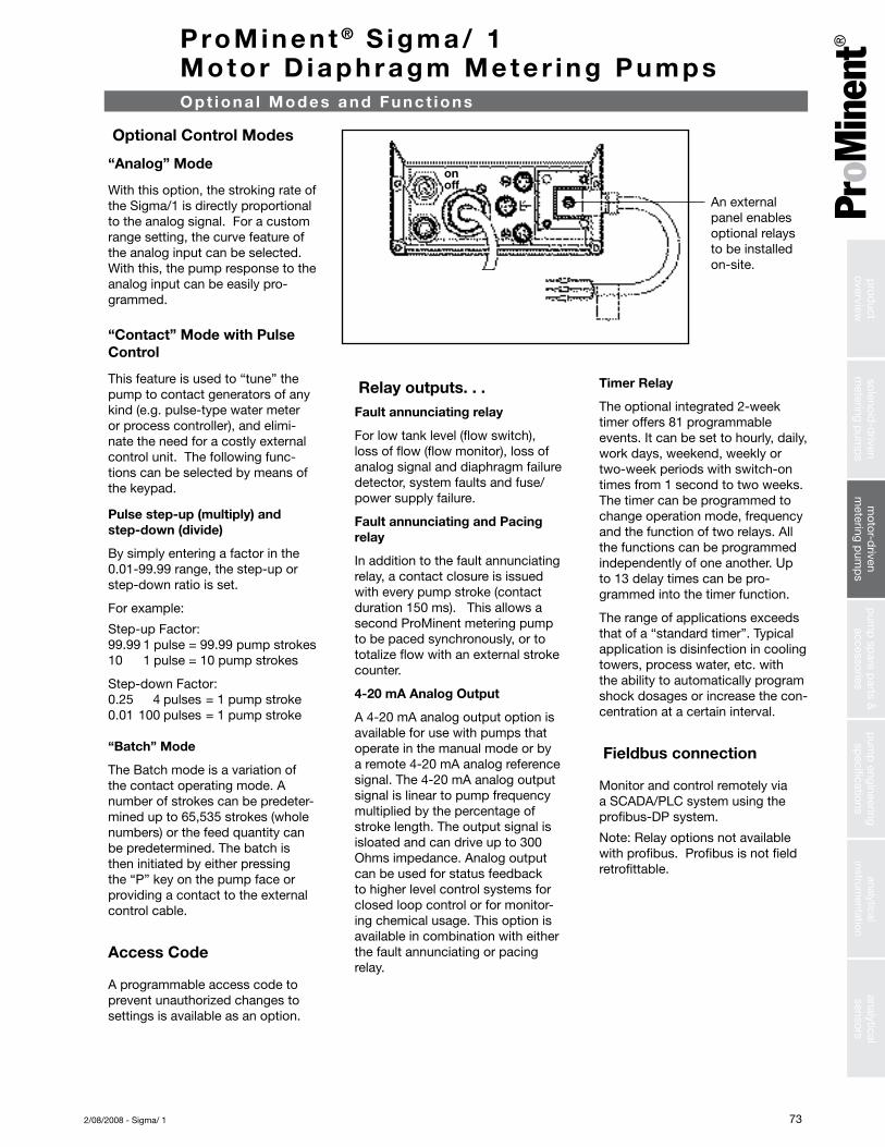
An external panel enablesoptional relays to be installed on-site.
onoff
analyticalsensors
analyticalinstrum
entationp
ump
engineeringsp
ecificationsp
ump
spare p
arts &accessories
motor-d
rivenm
etering pum
ps
solenoid-d
rivenm
etering pum
ps
prod
uctoverview
74 2/08/2008 - Sigma/ 1
ProMinent ® S igma/ 1 Motor D iaphragm Mete r ing PumpsSpec i f i ca t ions
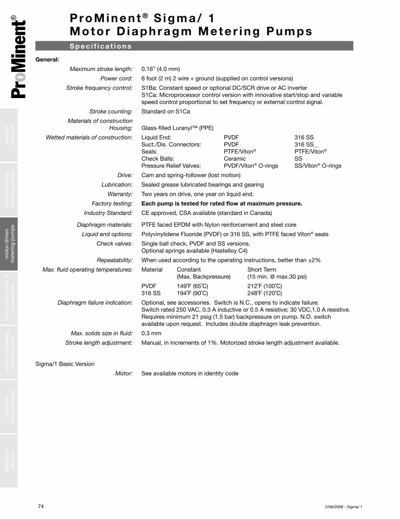
General: Maximum stroke length: 0.16” (4.0 mm)
Power cord: 6 foot (2 m) 2 wire + ground (supplied on control versions)
Stroke frequency control: S1Ba: Constant speed or optional DC/SCR drive or AC inverter S1Ca: Microprocessor control version with innovative start/stop and variable speed control proportional to set frequency or external control signal.
Stroke counting: Standard on S1Ca
Materials of construction Housing: Glass-filled Luranyl™ (PPE)
Wetted materials of construction: Liquid End: PVDF 316 SS Suct./Dis. Connectors: PVDF 316 SS Seals: PTFE/Viton® PTFE/Viton®
Check Balls: Ceramic SS Pressure Relief Valves: PVDF/Viton® O-rings SS/Viton® O-rings
Drive: Cam and spring-follower (lost motion)
Lubrication: Sealed grease lubricated bearings and gearing
Warranty: Two years on drive, one year on liquid end.
Factory testing: Each pump is tested for rated flow at maximum pressure.
Industry Standard: CE approved, CSA available (standard in Canada)
Diaphragm materials: PTFE faced EPDM with Nylon reinforcement and steel core
Liquid end options: Polyvinylidene Fluoride (PVDF) or 316 SS, with PTFE faced Viton® seals
Check valves: Single ball check, PVDF and SS versions. Optional springs available (Hastelloy C4)
Repeatability: Whenusedaccordingtotheoperatinginstructions,betterthan±2%
Max. fluid operating temperatures: Material Constant Short Term (Max. Backpressure) (15 min. @ max.30 psi)
PVDF 149˚F (65˚C) 212˚F (100˚C) 316 SS 194˚F (90˚C) 248˚F (120˚C)
Diaphragm failure indication: Optional, see accessories. Switch is N.C., opens to indicate failure. Switch rated 250 VAC, 0.3 A inductive or 0.5 A resistive; 30 VDC,1.0 A resistive. Requires minimum 21 psig (1.5 bar) backpressure on pump. N.O. switch available upon request. Includes double diaphragm leak prevention.
Max. solids size in fluid: 0.3 mm
Stroke length adjustment: Manual,inincrementsof1%.Motorizedstrokelengthadjustmentavailable.
Sigma/1 Basic Version
Motor: See available motors in identity code
sole
noid
-driv
enm
eter
ing
pum
ps
mot
or-d
riven
met
erin
g p
ump
sp
ump
sp
are
par
ts &
acce
ssor
ies
pum
p e
ngin
eerin
gsp
ecifi
catio
nsan
alyt
ical
inst
rum
enta
tion
anal
ytic
alse
nsor
sp
rod
uct
over
view
752/08/2008 - Sigma/ 1
ProMinent ® S igma/ 1 Motor D iaphragm Mete r ing PumpsSpec i f i ca t ions
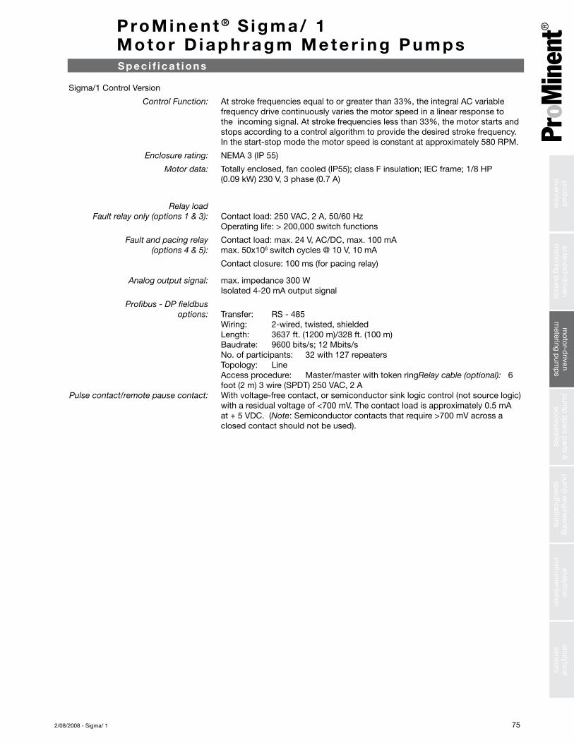
Sigma/1 Control Version
Control Function: Atstrokefrequenciesequaltoorgreaterthan33%,theintegralACvariablefrequency drive continuously varies the motor speed in a linear response to theincomingsignal.Atstrokefrequencieslessthan33%,themotorstartsandstops according to a control algorithm to provide the desired stroke frequency. In the start-stop mode the motor speed is constant at approximately 580 RPM.
Enclosure rating: NEMA 3 (IP 55)
Motor data: Totally enclosed, fan cooled (IP55); class F insulation; IEC frame; 1/8 HP (0.09 kW) 230 V, 3 phase (0.7 A)
Relay load Fault relay only (options 1 & 3): Contact load: 250 VAC, 2 A, 50/60 Hz Operating life: > 200,000 switch functions
Fault and pacing relay Contact load: max. 24 V, AC/DC, max. 100 mA (options 4 & 5): max. 50x106 switch cycles @ 10 V, 10 mA
Contact closure: 100 ms (for pacing relay)
Analog output signal: max. impedance 300 W Isolated 4-20 mA output signal
Profibus - DP fieldbus options: Transfer: RS - 485 Wiring: 2-wired, twisted, shielded Length: 3637 ft. (1200 m)/328 ft. (100 m) Baudrate: 9600 bits/s; 12 Mbits/s No. of participants: 32 with 127 repeaters Topology: Line Access procedure: Master/master with token ringRelay cable (optional): 6 foot (2 m) 3 wire (SPDT) 250 VAC, 2 A Pulse contact/remote pause contact: With voltage-free contact, or semiconductor sink logic control (not source logic) with a residual voltage of <700 mV. The contact load is approximately 0.5 mA at + 5 VDC. (Note: Semiconductor contacts that require >700 mV across a closed contact should not be used).
analyticalsensors
analyticalinstrum
entationp
ump
engineeringsp
ecificationsp
ump
spare p
arts &accessories
motor-d
rivenm
etering pum
ps
solenoid-d
rivenm
etering pum
ps
prod
uctoverview

76 2/08/2008 - Sigma/ 1
Liquid End Suction/Discharge Valve Seals/ Balls connector ball seat
PVT PVDF (Polyvinylidenefluoride) PVDF (Polyvinylidenefluoride) PTFE/PTFE Ceramic
SST Stainless steel Stainless steel PTFE/PTFE Stainless steel
M ater ia l s I n Contac t W i th Chemica ls
P roMinent ® S igma/ 1 Motor D iaphragm Mete r ing Pumps
Technical 60 Hz (1750 RPM) operation Max. Output Max. Max. Suction/ Shipping data: Capacity at Maximum Stroke per Suction Suction Discharge Weight Pressure Rate Stroke Lift Pressure Connector w/Motor
Pump Version psig (bar) U.S. (L/h) Stroke/ mL/ (water) psig (bar) DN in. (approx.)S1Ba HM GPH min. stroke ft. (m) lbs. (kg)
12017 PVT 145 (10) 5.3 (20) 88 4 23 (7) 14.5 (1) 10 1/2 MNPT 19.8 (9)12017 SST 174 (12) 5.3 (20) 88 4 23 (7) 14.5 (1) 10 3/8 FNPT 26.5 (12)12035 PVT 145 (10) 11.1 (42) 172 4 23 (7) 14.5 (1) 10 1/2 MNPT 19.8 (9)12035 SST 174 (12) 11.1 (42) 172 4 23 (7) 14.5 (1) 10 3/8 FNPT 26.5 (12)10050 PVT 145 (10) 15.8 (60) 240 4 23 (7) 14.5 (1) 10 1/2 MNPT 19.8 (9)10050 SST 145 (10) 15.8 (60) 240 4 23 (7) 14.5 (1) 10 3/8 FNPT 26.5 (12)
10022 PVT 145 (10) 6.8 (26) 88 5.1 19.6 (6) 14.5 (1) 10 1/2 MNPT 19.8 (9)10022 SST 145 (10) 6.8 (26) 88 5.1 19.6 (6) 14.5 (1) 10 3/8 FNPT 26.5 (12)10044 PVT 145 (10) 14 (53) 172 5.1 19.6 (6) 14.5 (1) 10 1/2 MNPT 19.8 (9)10044 SST 145 (10) 14 (53) 172 5.1 19.6 (6) 14.5 (1) 10 3/8 FNPT 26.5 (12)07065 PVT 102 (7) 20.6 (78) 240 5.1 19.6 (6) 14.5 (1) 10 1/2 MNPT 19.8 (9)07065 SST 102 (7) 20.6 (78) 240 5.1 19.6 (6) 14.5 (1) 10 3/8 FNPT 26.5 (12)
07042 PVT 102 (7) 13.2 (50) 88 9.7 9.8 (3) 14.5 (1) 15 3/4 MNPT 21 (9.5)07042 SST 102 (7) 13.2 (50) 88 9.7 9.8 (3) 14.5 (1) 15 1/2 FNPT 29.8 (13.5)04084 PVT 58 (4) 26.7 (101) 172 9.7 9.8 (3) 14.5 (1) 15 3/4 MNPT 21 (9.5)04084 SST 58 (4) 26.7 (101) 172 9.7 9.8 (3) 14.5 (1) 15 1/2 FNPT 29.8 (13.5)04120 PVT 58 (4) 38 (144) 240 9.7 9.8 (3) 14.5 (1) 15 3/4 MNPT 21 (9.5)04120 SST 58 (4) 38 (144) 240 9.7 9.8 (3) 14.5 (1) 15 1/2 FNPT 29.8 (13.5)
Sigma/1 Basic Version
Technical 60 Hz operation Max. Output Max. Max. Suction/ Shipping data: Capacity at Maximum Stroke per Suction Suction Discharge Weight Pressure Rate Stroke Lift Pressure Connector w/Motor
Pump Version psig (bar) U.S. (L/h) Stroke/ mL/ (water) psig (bar) DN in. (approx.)S1Ca HM GPH min. stroke ft. (m) lbs. (kg)
12017 PVT 145 (10) 5.3 (20) 90 4 23 (7) 14.5 (1) 10 1/2 MNPT 19.8 (9)12017 SST 174 (12) 5.3 (20) 90 4 23 (7) 14.5 (1) 10 3/8 FNPT 26.5 (12)12035 PVT 145 (10) 11.1 (42) 170 4 23 (7) 14.5 (1) 10 1/2 MNPT 19.8 (9)12035 SST 174 (12) 11.1 (42) 170 4 23 (7) 14.5 (1) 10 3/8 FNPT 26.5 (12)10050 PVT 145 (10) 13.2 (50) 200 4 23 (7) 14.5 (1) 10 1/2 MNPT 19.8 (9)10050 SST 145 (10) 13.2 (50) 200 4 23 (7) 14.5 (1) 10 3/8 FNPT 26.5 (12)
10022 PVT 145 (10) 6.8 (26) 90 5.1 19.6 (6) 14.5 (1) 10 1/2 MNPT 19.8 (9)10022 SST 145 (10) 6.8 (26) 90 5.1 19.6 (6) 14.5 (1) 10 3/8 FNPT 26.5 (12)10044 PVT 145 (10) 14 (53) 170 5.1 19.6 (6) 14.5 (1) 10 1/2 MNPT 19.8 (9)10044 SST 145 (10) 14 (53) 170 5.1 19.6 (6) 14.5 (1) 10 3/8 FNPT 26.5 (12)07065 PVT 102 (7) 17.2 (65) 200 5.1 19.6 (6) 14.5 (1) 10 1/2 MNPT 19.8 (9)07065 SST 102 (7) 17.2 (65) 200 5.1 19.6 (6) 14.5 (1) 10 3/8 FNPT 26.5 (12)
07042 PVT 102 (7) 13.2 (50) 90 9.7 9.8 (3) 14.5 (1) 15 3/4 MNPT 21 (9.5)07042 SST 102 (7) 13.2 (50) 90 9.7 9.8 (3) 14.5 (1) 15 1/2 FNPT 29.8 (13.5)04084 PVT 58 (4) 26.7 (101) 170 9.7 9.8 (3) 14.5 (1) 15 3/4 MNPT 21 (9.5)04084 SST 58 (4) 26.7 (101) 170 9.7 9.8 (3) 14.5 (1) 15 1/2 FNPT 29.8 (13.5)04120 PVT 58 (4) 31.7 (120) 200 9.7 9.8 (3) 14.5 (1) 15 3/4 MNPT 21 (9.5)04120 SST 58 (4) 31.7 (120) 200 9.7 9.8 (3) 14.5 (1) 15 1/2 FNPT 29.8 (13.5)
Note: Universal control cable necessary for external Sigma control. (see page 138)
Sigma/1 Control Version
Capac i t y Da ta
sole
noid
-driv
enm
eter
ing
pum
ps
mot
or-d
riven
met
erin
g p
ump
sp
ump
sp
are
par
ts &
acce
ssor
ies
pum
p e
ngin
eerin
gsp
ecifi
catio
nsan
alyt
ical
inst
rum
enta
tion
anal
ytic
alse
nsor
sp
rod
uct
over
view
772/08/2008 - Sigma/ 1
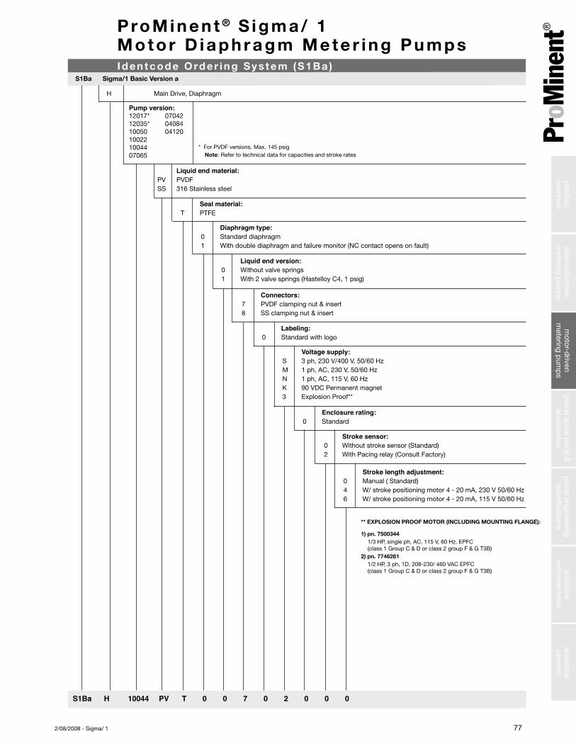
ProMinent ® S igma/ 1 Motor D iaphragm Mete r ing PumpsIdentcode Order ing Sys tem (S1Ba )
S1Ba Sigma/1 Basic Version a
H Main Drive, Diaphragm
Pump version:12017* 07042 12035* 0408410050 0412010022 1004407065
S1Ba H 10044 PV T 0 0 7 0 2 0 0 0
Liquid end material:PV PVDFSS 316 Stainless steel
Seal material:T PTFE
Diaphragm type:0 Standard diaphragm1 With double diaphragm and failure monitor (NC contact opens on fault)
Liquid end version:0 Without valve springs1 With 2 valve springs (Hastelloy C4, 1 psig)
Connectors:7 PVDF clamping nut & insert8 SS clamping nut & insert
Labeling:0 Standard with logo
Voltage supply:S 3 ph, 230 V/400 V, 50/60 HzM 1 ph, AC, 230 V, 50/60 HzN 1 ph, AC, 115 V, 60 HzK 90 VDC Permanent magnet3 Explosion Proof**
Stroke sensor:0 Without stroke sensor (Standard)2 With Pacing relay (Consult Factory)
Enclosure rating:0 Standard
Stroke length adjustment:0 Manual ( Standard)4 W/ stroke positioning motor 4 - 20 mA, 230 V 50/60 Hz6 W/ stroke positioning motor 4 - 20 mA, 115 V 50/60 Hz
* For PVDF versions. Max. 145 psig Note: Refer to technical data for capacities and stroke rates
** EXPLOSION PROOF MOTOR (INCLUDING MOUNTING FLANGE):
1) pn. 7500344 1/3 HP, single ph, AC, 115 V, 60 Hz, EPFC
(class 1 Group C & D or class 2 group F & G T3B)2) pn. 7746261 1/2 HP, 3 ph, 1D, 208-230/ 460 VAC EPFC
(class 1 Group C & D or class 2 group F & G T3B)
analyticalsensors
analyticalinstrum
entationp
ump
engineeringsp
ecificationsp
ump
spare p
arts &accessories
motor-d
rivenm
etering pum
ps
solenoid-d
rivenm
etering pum
ps
prod
uctoverview

78 2/08/2008 - Sigma/ 1
Stroke length adjustment:
C Manual + Calibration
Flow monitor:0 Input for metering monitor
signal (pulse)1 Input for maintained flow
switch signal
Access code:0 No access code1 Access code
Control variants:0 Manual + External with pulse control (multi-
plier/divider)1 Manual + External with pulse control & ana-
log control4 Option 0 + timer5 Option 1 + timerP Option 1 + Profibus (Relay must be 0)
Relay:0 Without relay1 Fault annunciating relay, drops out3 Fault annunciating relay, pulls in4 Option 1 + pacing relay5 Option 3 + pacing relayC 4-20 mA output, drops outD 4-20 mA output, pulls inE 4-20 mA output, pacing relay
Cable and plug with 6 ft (2 m) power cord, single phase:A European plug, 230 VD N. American plug, 115 VU N. American plug, 230 V
Voltage supply: U 1 ph, 115-230 V +10%,50/60Hz
Labeling:0 Standard with logo
Connectors:7 PVDF clamping nut & insert8 SS clamping nut & insert
Liquid end version:0 Without valve springs1 With 2 valve springs (Hastelloy C4, 1.45 psig)
Diaphragm type:0 Standard diaphragm, PTFE1 With double diaphragm and failure monitor (NC contact opens on fault)2 With double diaphragm and failure monitor (alarm & continues to operate)
Liquid end materials:PVT PVDF with PTFE gasketSST 316 Stainless steel with PTFE gasket
Pump version:12017* 10022 07042 *For PVDF versions, max. 145 psig12035* 10044 04084 10050 07065 04120 Note: Refer to technical data for capacities and stroke rates
Main drive H Main drive/Diaphragm
S1Ca H 07042 PVT 0 0 7 0 U D 0 0 0 0 C
Iden tcode Order ing Sys tem (S1Ca )
P roMinen t ® S igma/ 1 Motor D iaphragm Mete r ing Pumps
S1Ca Sigma/1 Control Version a
sole
noid
-driv
enm
eter
ing
pum
ps
mot
or-d
riven
met
erin
g p
ump
sp
ump
sp
are
par
ts &
acce
ssor
ies
pum
p e
ngin
eerin
gsp
ecifi
catio
nsan
alyt
ical
inst
rum
enta
tion
anal
ytic
alse
nsor
sp
rod
uct
over
view
792/08/2008 - Sigma/ 1
ProMinent ® S igma/ 1 Motor D iaphragm Mete r ing Pumps
7.7 (196)
5.4 (136)
4.7 (120)A
B Fmax.1.4 (36)
E/E1
D/D1
1.1 (28)
0.25 (6.5)
4.7 (120)
7.8 (197)
6.3
(160
)
14.9
(378
)***
C
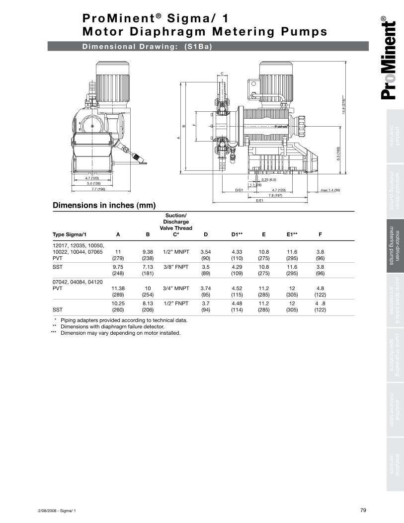
Suction/ Discharge Valve ThreadType Sigma/1 A B C* D D1** E E1** F
12017, 12035, 10050, 10022, 10044, 07065 11 9.38 1/2” MNPT 3.54 4.33 10.8 11.6 3.8PVT (279) (238) (90) (110) (275) (295) (96)
SST 9.75 7.13 3/8” FNPT 3.5 4.29 10.8 11.6 3.8 (248) (181) (89) (109) (275) (295) (96)
07042, 04084, 04120 PVT 11.38 10 3/4” MNPT 3.74 4.52 11.2 12 4.8 (289) (254) (95) (115) (285) (305) (122)
10.25 8.13 1/2” FNPT 3.7 4.48 11.2 12 4 .8SST (260) (206) (94) (114) (285) (305) (122)
Dimensions in inches (mm)
* Piping adapters provided according to technical data. ** Dimensions with diaphragm failure detector. *** Dimension may vary depending on motor installed.
Dimens iona l Draw ing : (S1B a )
analyticalsensors
analyticalinstrum
entationp
ump
engineeringsp
ecificationsp
ump
spare p
arts &accessories
motor-d
rivenm
etering pum
ps
solenoid-d
rivenm
etering pum
ps
prod
uctoverview

80 2/08/2008 - Sigma/ 1
ProMinent ® S igma/ 1 Motor D iaphragm Mete r ing PumpsDimens iona l Draw ing : (S1Ca )
A
B F
E/E1
D/D1
C
7.7 (196)
5.4 (136)
4.7 (120)
1.1 (28)
0.25 (6.5)
4.7 (120 )max. 1.4(36)
7.8 (197)
6.3
(160
)
14.9
(378
)
Suction/ Discharge Valve ThreadType Sigma/1 A B C* D D1** E E1** F
12017, 12035, 10050, 10022, 10044, 07065 11 9.38 1/2” MNPT 3.54 4.33 10.8 11.6 3.8PVT (279) (238) (90) (110) (275) (295) (96)
SST 9.75 7.13 3/8” FNPT 3.5 4.29 10.8 11.6 3.8 (248) (181) (89) (109) (275) (295) (96)
07042, 04084, 04120 PVT 11.38 10 3/4” MNPT 3.74 4.52 11.2 12 4.8 (289) (254) (95) (115) (285) (305) (122)
10.25 8.13 1/2” FNPT 3.7 4.48 11.2 12 4 .8SST (260) (206) (94) (114) (285) (305) (122)
Dimensions in inches (mm)
* Piping adapters provided according to technical data. ** Dimensions with diaphragm failure detector.
sole
noid
-driv
enm
eter
ing
pum
ps
mot
or-d
riven
met
erin
g p
ump
sp
ump
sp
are
par
ts &
acce
ssor
ies
pum
p e
ngin
eerin
gsp
ecifi
catio
nsan
alyt
ical
inst
rum
enta
tion
anal
ytic
alse
nsor
sp
rod
uct
over
view