Embed Size (px)
Citation preview

(IJACSA) International Journal of Advanced Computer Science and Applications,
Vol. 8, No. 2, 2017
119 | P a g e
www.ijacsa.thesai.org
Prolonging the Network Lifetime of WSN by using
the Consumed Power Fairly Protocol
Ahmed Jamal Ahmed
Communication Engineering Department
Universiti Tun Hussein Onn Malaysia,
Parit Raja, Malaysia 86400
Jiwa Abdullah
Communication Engineering Department
Universiti Tun Hussein Onn Malaysia,
Parit Raja, Malaysia 86400
Abstract—In wireless sensor networks (WSN), energy saving
is always a key concern. Since nodes have limited power, some of
them may use specific routes, thus leading to exhaustion of
intermediate nodes. These nodes die, which results in routing
holes in the network. Consequently, the overall throughput of the
network may get reduced. Therefore, in this study, the
mathematical proposed model is leaded to optimal route by
depending on equal power consumption from whole nodes in the
network. Moreover, a new routing protocol model was designed.
The protocol is termed as Consumed Power Fairly (CPF). This
protocol could achieve high power efficiency by distributing
power consumption equally to all nodes in the network. Our
proposed model works on finding the route to destination with
high power availability after summation of the total power for all
nodes from the source to the destination node, thus subtracting
the power consumption for particular data required to send. In
short, the proposal CPF protocol reduces the number of dead
nodes and keeps the connectivity high, which increases
prolonging the network lifetime.
Keywords—WSN; network topology; energy consumption;
graph theory; Consumed Power Fairly
I. INTRODUCTION
Wireless sensor network (WSN) consists typically of multiple autonomous, tiny, low cost and low power sensor nodes. These nodes gather data about their environment and collaborate to forward sensed data to centralized backend units called base stations or sinks for further processing [1]. WSN is known as a kind of wireless ad hoc networks [2]. In sensor networks, energy saving is always a key concern due to various reasons. Some of environments might be very dangerous [3]. Supplying energy through batteries, solar cells energy, other local energy sources are viable options though such challenges are limited to prolong the lifetime of WSN [4]. Therefore, it is important to minimize power requirements across all levels of the protocol stack and minimize the amount of message passing for network control and coordination.
In the field of WSN, recharging is almost impossible due to the small size required for sensors, and large physically distributed networks increase the difficulty of changing batteries [5]. Therefore, researchers and system developers toured to develop the WSN architecture or network layer to minimize energy consumption in order to make the network and overall system application more energy efficient.
The IEEE 802.15.4 standard is specifically meant to support long battery life time [6]. Yet, there are still some
precautions to be taken by which a sensor network system application that is based on the standard can run for a longer period of time [7]. Thus, routing is recognized as an essential feature of every network because it is the backbone of a network and it is in charge of forwarding packets among nodes [8]. The routing protocol layer plays an important role in improving the performance of wireless sensor networks for fixed and mobile nodes in the network [9, 10]. Forwarding an amount of data from one node to sink node through intermediate nodes leads to fast death of nodes, especially those nodes which are near to the sink node [3, 11-14]. This will increase the possibility of the whole network death. Therefore, in this study, the demonstrated routing protocol for WSN that is capable of achieving high power efficiency by distributing power consumption equally to all nodes in the network. The sensor node near the sink consumes more power than others, which leads speedy death of nodes and shortening the network lifetime.
As previously stated, in the field of WSN, nodes have limited power, and therefore, some nodes use specific routes, which exhausts the intermediate nodes [15]. Consequently, these nodes die, thus resulting into routing holes in the network that harm the overall network. Furthermore, several problems such as (Shortest path problems, Network flow problems, Matching problems, 2-SAT problem, Traveling Salesman Problem (TSP), and many more) can be formulated and solved by graphs. They use different methods to calculate and select the optimal route from a source to a destination node. To achieve a prolonging lifetime of WSN by fining the optimal path that depends on distributing power consumption on the whole WSN network equally, it is sufficient to achieve energy saving over the whole network. Thus, the study aimed to design a routing protocol for WSN that is able to achieve high power efficiency by distributing power consumption equally on all nodes in the network.
This paper is organized as follows. Section II introduces the mathematical model of energy consumption for our new routing protocol used to find the optimal path. Followed by section III, triangular matrix table to representing a computer network mathematically and graphically. The network topology is represented using a triangular matrix to obtain full topology information. This is followed by Section IV presents the experimental modeling to measure real energy consume to sending and receiving data packets by using CC2420 device (IEEE 802.15.4). As result section V packet energy consumption explain the routing implementation and how to
(IJACSA) International Journal of Advanced Computer Science and Applications,
Vol. 8, No. 2, 2017
120 | P a g e
www.ijacsa.thesai.org
calculate power consumption for each path. Also discusses the method of finding a route inside the WSN. It concludes and shows the simulation and experimental results obtained by using MATLAB.
II. MATHEMATICAL MODEL OF ENERGY CONSUMPTION
FOR ROUTING
In this section, the description of mathematical model used to find the optimal path while transmitting data packets. The sensor node should know the measured value from the environment by reading the sensor value, and then, it should send them to the sink by multi hops and sleep till the next process iteration takes place. Our proposed model depends on finding the route to the destination with high power available after summation of the total power for all nodes from the source to the destination node, thus subtracting power consumption for particular data required to send. Our proposed model depends on network topology.
A graph is a data type structure, which has two components: vertices or nodes and the edges or links that connect them. Graphs can either be undirected or directed. Undirected graphs comprise a group of nodes and a group of links with no direction between a pair of nodes. A group of mobile nodes in a specific domain forms a network that can be represented by a graph. The edges represent the physical wireless connection link among devices, and allow physical transmission between nodes. Topology is defined as a mathematical study of shapes and spaces as represented in (1) where G (N, E) can be the topology graph, N can be the nodes, E stands for the links, and (i, j) refer to the link from Node i to Node j. Let the information be transmitted by f. The variable
vector
is then defined as follows:
{
( )
( ) (1)
The above equation indicates that the variable vector
is
one if the link (i, j) is used to transmit the flow f. Otherwise the vector will be zero if it cannot be used for transmission [16]. As shown in Fig. 1, in order to reach Node 2, only two possible routes exist from Node 5: through the first path ((5, 1) and (1, 2)) and through the second path (5,4), (4,3), and (3, 2)).
Fig. 1. Graph of routes from Nodes 5 to 2 [17]
Suppose that the
represent the power available in each
node. So, to calculate the total summation power available for
the first path while = 1, and
=1, first, the current power
saving (battery) in each node must be read. Assuming the destination node is a sink node that has the infinity power (no
battery). So that, it have to sum the power remaining
in Node i=5, and i=1 only (
, and
). In general, (2) shows the total power available to a specific path from the source to destination,
{∑
( )}
(2)
Where T.P denotes the total power available for one path, h represents the number of hops, and h= n-1 where n represents the number of nodes for that particular path.
In assuming that P.N denotes the total power needed (required) to transmit particular data from the source to the sink node, then, power consumption will depend on the receiver and transmitter circuit ( ). The number of particular
transmitted data will also be equal to the number of hops h, denoted as t=h, but for receiving is r=h-1. From the example above, Node 5 transmits only, whereas Node 1 receives and transmits as well. However, to transmit k bits with distance d, the energy consumed is expressed as follows:
( ) ( ) ( )
{
(3)
Where is the distance threshold for swapping
amplification models, which can be calculated as √
.
Then, the radio will consume power for a k-bit message through the receiving process.
( )
(4)
The total power needed for one path is calculated as.
∑ ( ) ∑ ( )
(5)
If supposed that there are a several of paths to the sink node, then the (2) and (3) should be vectors T.P =[ path1, path2,..pathn] and P.N=[ path1, path2,..pathn]. Subtracting T.P - P.N, collecting the remaining power in particular path within the vector as shown in (6).
∑{∑ ( )
}
(6)
Where, P.R represents the residual power for every possible path from the source to the sink node, and p represents the number of possible paths. Hence, P.R represents the vector of elements that give all possible residual power from the source to the sink node. The maximum number represents the optimal path to be selected to achieve a prolong network lifetime. Max
(IJACSA) International Journal of Advanced Computer Science and Applications,
Vol. 8, No. 2, 2017
121 | P a g e
www.ijacsa.thesai.org
{ P.R: optimal path i }. The sender node must find an optimal route based on network topology and power saving as illustrated in (6). Therefore, the next section explains how to find all possibly available paths based on the network topology.
III. TRIANGULAR MATRIX TABLE (TMT)
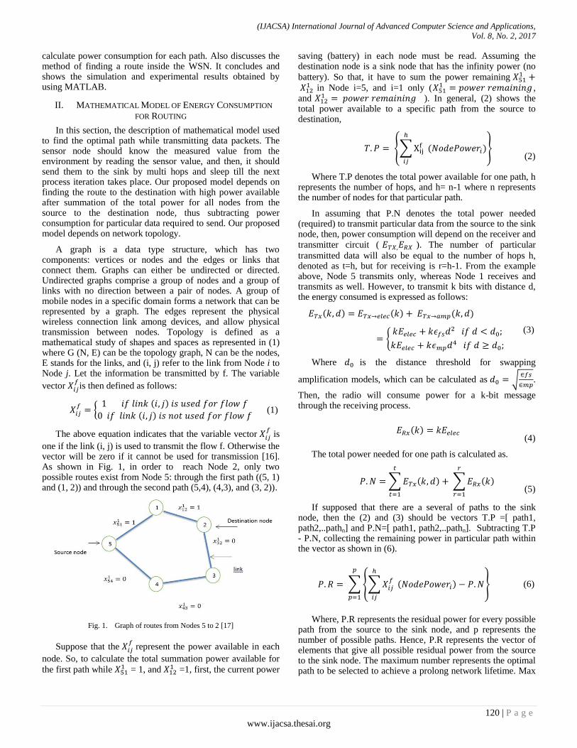
After representing a computer network mathematically and graphically, the network topology is represented using a triangular matrix to obtain full topology information. N is assumed to be the set of nodes and E is the set of links, where n denotes the number of network nodes, that is, n = |N|. Inside the network is a source node s ⋲ N and a destination node t ⋲ N, and (i, j) ⋲ E is the link from Node i to Node j. Using the Triangular Matrix Table (TMT) denotes saving the whole network topology information in a small memory size. First, dimensions of a triangular matrix are equal to the number of nodes, and each node inside the network has a number that represents the diagonal of the lower matrix. At first, the content of the lower matrix must be empty (zero). Each link between two nodes represents one bit inside the lower matrix. Otherwise, the lack of link between the two nodes means that each link will be represented by a zero bit inside the lower matrix depending on the cross of the row node with the column node for nodes with links. Fig. 2 shows the network topology which can be represented mathematically by using digit pairs: (1,2) , (1,3) , (1,4) , (1,5) , (2,3) , (2,4) , (2,5) , (3,4) , (3,5) , (4,5).
Fig. 2. Representation of Triangular Matrix Table (TMT) and undirected
graph
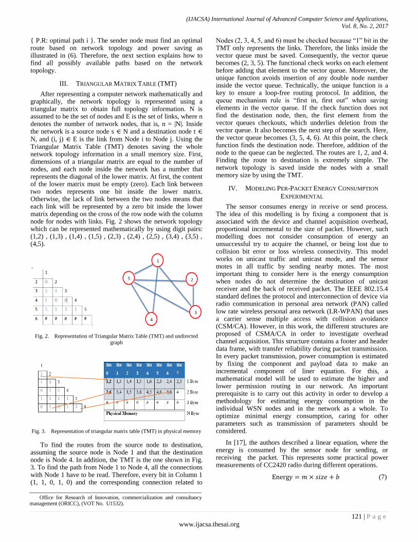
Fig. 3. Representation of triangular matrix table (TMT) in physical memory
To find the routes from the source node to destination, assuming the source node is Node 1 and that the destination node is Node 4. In addition, the TMT is the one shown in Fig. 3. To find the path from Node 1 to Node 4, all the connections with Node 1 have to be read. Therefore, every bit in Column 1 (1, 1, 0, 1, 0) and the corresponding connection related to
Nodes (2, 3, 4, 5, and 6) must be checked because “1” bit in the TMT only represents the links. Therefore, the links inside the vector queue must be saved. Consequently, the vector queue becomes (2, 3, 5). The functional check works on each element before adding that element to the vector queue. Moreover, the unique function avoids insertion of any double node number inside the vector queue. Technically, the unique function is a key to ensure a loop-free routing protocol. In addition, the queue mechanism rule is “first in, first out” when saving elements in the vector queue. If the check function does not find the destination node, then, the first element from the vector queues checkouts, which underlies deletion from the vector queue. It also becomes the next step of the search. Here, the vector queue becomes (3, 5, 4, 6). At this point, the check function finds the destination node. Therefore, addition of the node to the queue can be neglected. The routes are 1, 2, and 4. Finding the route to destination is extremely simple. The network topology is saved inside the nodes with a small memory size by using the TMT.
IV. MODELING PER-PACKET ENERGY CONSUMPTION
EXPERIMENTAL
The sensor consumes energy in receive or send process. The idea of this modelling is by fixing a component that is associated with the device and channel acquisition overhead, proportional incremental to the size of packet. However, such modelling does not consider consumption of energy an unsuccessful try to acquire the channel, or being lost due to collision bit error or loss wireless connectivity. This model works on unicast traffic and unicast mode, and the sensor motes in all traffic by sending nearby motes. The most important thing to consider here is the energy consumption when nodes do not determine the destination of unicast receiver and the back of received packet. The IEEE 802.15.4 standard defines the protocol and interconnection of device via radio communication in personal area network (PAN) called low rate wireless personal area network (LR-WPAN) that uses a carrier sense multiple access with collision avoidance (CSM/CA). However, in this work, the different structures are proposed of CSMA/CA in order to investigate overhead channel acquisition. This structure contains a footer and header data frame, with transfer reliability during packet transmission. In every packet transmission, power consumption is estimated by fixing the component and payload data to make an incremental component of liner equation. For this, a mathematical model will be used to estimate the higher and lower permission routing in our network. An important prerequisite is to carry out this activity in order to develop a methodology for estimating energy consumption in the individual WSN nodes and in the network as a whole. To optimize minimal energy consumption, caring for other parameters such as transmission of parameters should be considered.
In [17], the authors described a linear equation, where the energy is consumed by the sensor node for sending, or receiving the packet. This represents some practical power measurements of CC2420 radio during different operations.
(7)
Office for Research of Innovation, commercialization and consultancy management (ORICC), (VOT No. U1532).

(IJACSA) International Journal of Advanced Computer Science and Applications,
Vol. 8, No. 2, 2017
122 | P a g e
www.ijacsa.thesai.org
Where coefficients m and b stand for various operations, m represents the incremental cost and b represents fixed costs [18]. Moreover, the size represents the payload (data packet) by the number of bytes. Therefore, power consumption to send packet is:
( ) ( ) ( ) (8)
And for receiving packet is:
( ) ( ) ( ) (9)
The LR-WPAN defines four frame structures:
A. Data frame
Based on the data frame structure as shown in Fig. 5, the length of the physical data packet is 11 bytes + (0 to 20 bytes) + n bytes, where n represents the payload data. Practically, (6 bytes) is needed for addressing purposes. Where, (2-byte) addresses are assigned to the sensor motes, and (2 bytes) source PAN identifier is left empty. Then, (2 byte) destination PAN identifier is assigned. Therefore, the length of the data packet gets 11+6 + n bytes= 17 bytes + n byres.
B. Acknowledgment frame
The length of the acknowledgment packet is (11 bytes) based on the acknowledgment frame. However, to send data between two nodes, there are sender Node and receiver Node. The sender Node transmits a 17 +n bytes (data frame) and receive 11 bytes (acknowledgment frame). For the receiver Node, it also needs to receive 17 +n bytes (data frame) and sends 11 bytes (acknowledgment frame). Ignore beacons which are transmitted by the coordinator to provide synchronization services in IEEE 802.15.4. This is followed by calculating power consumption for CC2420 (Single-Chip 2.4 GHz IEEE 802.15.4 Compliant ZigBee) through either providing the synchronization of IEEE 802.15.4 if not used in PAN or transmitting the MAC sub-layer using CSMA/CA as follows: 1-initializing the local back off variables or random back off period.2. Then, clear channel assessment to ensure channel is free. 3. After that, data should be transmitted 4. Finally, the acknowledgment frame should be used.
The first step is not included in the measurement and this first step is an internal step in measuring the upper and the lower bounds of energy consumption of rout. Based on the IEEE802.15.4 framework, there is no listening before receiving the acknowledgement by the data transmitter. Moreover, there is no clear channel assessment before sending the acknowledgment by the receiver of the data frame.
Clear Channel Assessment CCA and Sending: To measure the power needed for sending operation. It requires a 46-byte packet. Where 28 bytes data payload and 18 bytes header and footer. Therefore, power consumptions to send 1 byte, 11 bytes and 18 bytes are 0.12 mJ, 1.32 mJ and 2.16 mJ, respectively.
Listening and Receiving: To measure receiving power consumption needed for Listening and Receiving operations, and this requires a 46-byte packet for receiving. There is listening for the duration of 10 ms which is a short periodic receive check before receiving
the data. It takes 0.58 mJ. Therefore, power consumptions to receive 1 byte, 11 bytes and 18 bytes are 0.12 mJ, 1.3 mJ and 2.13 mJ, respectively. However, based on previous measurements (8) and (9) are written as follows:
( ) ( ) ( ) (10)
( ) ( ) ( ) (11)
V. CPF PROTOCOL AND PACKET ENERGY CONSUMPTION
In this section, the routing implementation and how to calculate power consumption for each path in finding the optimal one are explained. In this simulation, using 100 m × 100 m area with 100 Nodes (sensors) scattered randomly. As shown in Fig. 4, the sink node has unlimited power, and it is located in the central area represented by the green color. The simulation parameters are illustrated in Table 1. Basically, sensor nodes use battery such as Nickel Metal Hydride rechargeable. With regular AA, all batteries have a nominal voltage. The charge capacity (C) of battery finishes during time, usually specified as how many amperes a battery can deliver during one hour. For instance, suppose a battery has C = 1200 mAh, this means 1.2 Amperes (1200 mA) for one hour. To measure the total enrage equivalent to the number of Joules, this is performed as follows: Energy (Joules) = Current * 1hour * 3600 sec / 1 hour * V = 1200 mA * 1 hour * 3600 sec / 1 hour * 1.2 V = 5184 Joule. In addition, for each bit, our radio model is assumed to dissipate the energy = 50nJ/bit to run the transmitter or receiver circuit. To transmit the data bits over a distance (d).
TABLE I. SIMULATION PARAMETER
Operation Parameter Values
Transmitter/Receiver
Electronics 50nJ/bit
Entail power 0.5J
Number of bits k 4000
Number of nodes n 100
Transmit Amplifier if dmax
<= €fs 10pJ/bit/m2
Transmit Amplifier if dmax
>= €mp 0.0013pJ/bit/m4
area x, y 100 m × 100 m
After running the simulation, the first nod dies after 325 iterations of sending the data. Where Node ID is 34. Then, after that, Nodes 35, 36, 44, and 46 die accordingly. Fig. 4 (b) represents the network after 800 iterations of sending the data where the sink node is in the center. Observing the most of nodes die are those nodes which are near to the sink node. This death of such nodes is due to their frequent usage as intermediate nodes when transmitting the data more than the edge nodes. Consequently, they consume more power and die first. In the same experiment, the sink node moves to upper as shown in Fig. 5. The number of dead node increases from 5

(IJACSA) International Journal of Advanced Computer Science and Applications,
Vol. 8, No. 2, 2017
123 | P a g e
www.ijacsa.thesai.org
nodes in Fig. 4 to 16 nodes in Fig. 5. This occurs due to the same reason mentioned above. It also means that routing protocols do not consume power equally from all nodes in the network. This also happens even in the case of applying energy aware protocols as shown in Fig. 4 and 5.
(a) Network topology for 100 sensors
(b) Network topology with dying nodes
Fig. 4. Network topology for 100 sensors with sink node in the center of
field
(a) Network topology for 100 sensors
(b) Network topology with dying nodes
Fig. 5. Network topology for 100 sensors with sink node in the top of field
Because of this problem, the proposed mathematical model can be find the optimal route by consuming power equally from all nodes in the network. The optimal route is proved in the result section by comparing it with previous studies. This resulted in increasing the lifetime of the network. Our new proposed Consume Power Fairly (CPF) protocol method is illustrated below:

(IJACSA) International Journal of Advanced Computer Science and Applications,
Vol. 8, No. 2, 2017
124 | P a g e
www.ijacsa.thesai.org
1) Adding a Triangular Matrix Table for every node in the
network to save the whole network topology information.
2) Using a table to save the power remaining for every
node in the network.
3) Finding the possibility of all routes to the destination
node (sink) with the help of TMT.
4) Applying our proposed equations to find the best route.
As follows:
5) Assuming that the Path consists of several intermediate
nodes to the destination. Then, the total power for that route is
stated as in (2).
a) The power needed to transmit a particular data is
given in (5), which is the power required to transmit a
particular size data.
b) (6) provides the total residual power for that
particular route, where the result gives several paths.
-Triangular Matrix Table
-Power remaining table
-PRinitial=0
Find all possible routes
Optimal path=pathnumber
For each path
-Calculate Energy dissipated Tx
-Calculate Energy dissipated Rx
-PRt(Eq6)= TP(Eq2)-PN(Eq5)
No
If path==last path
No
pathnumber= path;
PRinitial=PRt;
Send data packet
if (PRt>PRinitial)
Yes
Yes
Start
End
Fig. 6. Method of protocol
However, the optimal route that is selected depends on getting the high number of PR after applying new proposed (6). As a result, prolonging Node Lifetime is increased by applying new Consume Power Fairly (CPF) protocol compared with energy aware protocol as shown in Fig. 7.
(a) Energy aware protocol
(b) Consume Power Fairly protocol
Fig. 7. Network topology for energy aware protocol compared to CPF
protocol
In Fig. 8 (a), the energy aware protocol generates holes of dying nodes that will affect the whole network. Consequently, the network will die fast. In Fig. 8 (b), the number of dying nodes is 6 if compared with 10 dying nodes for energy aware protocol. The iteration of sending data is 1000 number of rounds for both results. Secondly, the dying node distributed in the field will not affect the rest of other nodes where the holes affect the dying node itself only (See Fig. 8-b).
Fig. (8) illustrates how the number of dying nodes affects the network overall. The energy aware protocol generates a big hole around the sink node through 1200 iteration as shown in Fig. 9 (a). This will cause fast death to the whole network. This is because these protocols depend on energy aware protocols that select the optimal path with minimum hops count. In addition, they do not consider the network topology to keep the network live for a long period. Unlike this, our proposed model considers network topology with the help of TMT as shown in (2), (5), and (6) to select the optimal path. Selecting the optimal path may not be the minimum hops count. Therefore, Fig. 9 (b) shows that the network topology is strongly connected, which reflects that the dying nodes do not affect the whole network connections. As a result, there is an increase in the prolonging network Lifetime. Fig. 10 also shows the number of alive nodes. In summary, the proposal CPF protocol reduces the number of dead nodes and keeps the connectivity high, which increases prolonging network Lifetime.

(IJACSA) International Journal of Advanced Computer Science and Applications,
Vol. 8, No. 2, 2017
125 | P a g e
www.ijacsa.thesai.org
(a) Energy aware protocol
(b) Consume Power Fairly protocol
Fig. 8. Network topology after nodes dying for energy aware protocol
compared to CPF protocol for 100 sensors with dying nodes
(a) Energy aware protocol
(b) Consume Power Fairly protocol
Fig. 9. Network topology after 1200 number of iterations for 100 sensors
with dying nodes
Fig. 10. Number of alive nodes after 1200 iterations
TABLE II. COMPARE BETWEEN TWO PROTOCOLS
Iteration
No. of node
die at
consume power
fairly
No. of node die
at energy aware protocol
Consume
power fairly
network
status
Energy
aware
protocol
status
1000 6 10 Connected Small hole
1200 7 13 Connected Big hole

(IJACSA) International Journal of Advanced Computer Science and Applications,
Vol. 8, No. 2, 2017
126 | P a g e
www.ijacsa.thesai.org
VI. CONCLUSION
The main objective of this paper is to fulfil Prolonging Lifetime for WSN. In achieving this research objective, two contributions to previous research are offered. Firstly, the new mathematical model is proposed to increase the lifetime of WSN. Secondly, the mathematical model was applied to our new protocol called Consume Power Fairly (CPF), where selecting the optimal math depends on consume power fairly among all nodes inside the network to increase the lifetime of the network. An efficient route based on the power consumption and network topology are presented, which can effectively control and distribute the power over the whole WSN to save power for prolonging network lifetime.
ACKNOWLEDGMENT
The authors would like to thank the staff of wireless and radio science center (WARAS) of Universiti Tun Hussein Onn Malaysia (UTHM) for support. Research funding for this work is fully provided by Office for Research of Innovation, commercialization and consultancy management (ORICC), (VOT No. U1532).
REFERENCES
[1] S. Tanwar, N. Kumar, and J. J. P. C. Rodrigues, “A systematic review on heterogeneous routing protocols for wireless sensor network, ” Journal of Network and Computer Applications, vol. 53, pp. 39-56, 2015.
[2] C. Sergiou, V. Vassiliou, and A. Paphitis, “Congestion control in Wireless Sensor Networks through dynamic alternative path selection, ” Computer Networks, vol. 75, pp. 226-238, 2014.
[3] C. Sergiou, V. Vassiliou, and A. Paphitis, “Congestion control in Wireless Sensor Networks through dynamic alternative path selection, ” Computer Networks, vol. 75, Part A, pp. 226-238, 2014.
[4] A. Razaque and K. Elleithy, “Modular Energy-Efficient and Robust Paradigms for a Disaster-Recovery Process over Wireless Sensor Networks, ” Sensors, vol. 15, no.7, pp.16162-16195, 2015.
[5] L. Liu, N. Zhang, and Y. Liu, “Topology control models and solutions for signal irregularity in mobile underwater wireless sensor networks,” Journal of Network and Computer Applications, vol. 51, pp. 68-90, 2015.
[6] S. Chen, T. Sun, J. Yuan, X. Geng, C. Li, S. Ullah, et al., “Performance analysis of IEEE 802.15.4e Time Slotted Channel Hopping for low-rate wireless networks,” KSII Transactions on Internet and Information Systems, vol. 7, no. 1, pp. 1-21, 2013.
[7] A. A. T. Rahem, M. Ismail, I. A. Najm, and M. Balfaqih, “Topology sense and graph-based TSG: efficient wireless ad hoc routing protocol for WANET,” Telecommunication Systems, pp. 1-16, 2017.
[8] A. Saad, A. J. Hussein, I. A. Najm, and A. T. Rahem, “Vehicular ad hoc networks: Growth and survey for three layers,” Indian Journal of Science and Technology, vol. 7, no. 1, pp. 1-21, 2017.
[9] A. T. Rahem, M. ismail, M. Fadhil, and A. Jamal, “Studying and analyzing algorithm behavior and mechanism for wireless ad hoc routing protocols,” Journal of Engineering and Applied Sciences, vol. 11, no. 19, pp. 11760- 11769, 2016.
[10] A. T. Rahem, M. Ismail, A. Idri, and A. Dheyaa, “A comparative and analysis study of VANET routing protocols,” Journal of Theoretical and Applied Information Technology, vol. 66, no. 3, pp. 691-698, 2014.
[11] A. P. Silva, S. Burleigh, C. M. Hirata, and K. Obraczka, “A survey on congestion control for delay and disruption tolerant networks,” Ad Hoc Networks, vol. 25, Part B, pp. 480-494, 2015.
[12] N. Parrado and Y. Donoso, “Congestion Based Mechanism for Route Discovery in a V2I-V2V System Applying Smart Devices and IoT,” Sensors, vol. 15, no, 4, pp. 7768-7806, 2015.
[13] A. Ghaffari, “Congestion control mechanisms in wireless sensor networks: A survey, ” Journal of Network and Computer Applications, vol. 52, pp. 101-115, 2015.
[14] A. T. Rahem, M. Ismail, N. F. Abdullah, and M. Balfaqih, “Node cooperation to avoid early congestion detection congestion by alternative route based on cross-layer for wireless ad hoc networks,” IJECE, vol. 6, no. 5, pp. 2322-2330, 2016.
[15] R. F. Yezid Donoso, “Multi-Objective Optimization in Computer Networks Using Metaheuristics,” Boca Raton New York: AUERBACH PUBLICATIONS, Dec 12, 2010, Press.
[16] A. T. Rahem, M. Ismail, and A. Saad, “A triangular matrix routing table representation for efficient routing in manet,” Journal of Theoretical & Applied Information Technology, vol. 64, no. 2, pp.401-412, 2014.
[17] L. M. Feeney and M. Nilsson, “Investigating the energy consumption of a wireless network interface in an ad hoc networking environment,” in INFOCOM 2001. Twentieth Annual Joint Conference of the IEEE Computer and Communications Societies. Proceedings. IEEE, 2001, vol. 3, pp. 1548-1557.
[18] M. Amiri, “Evaluation of lifetime bounds of wireless sensor networks,” Computer Research Repository (CoRR), vol. abs/1011.2103, 2010.