Embed Size (px)
Citation preview
Prologue: Software Architectures and DocumentationBy Paul Clements,Felix Bachmann,Len Bass,David Garlan,James Ivers,Reed Little,Paulo Merson,Robert Nord,Judith Stafford
Date: Nov 11, 2010
Sample Chapter is provided courtesy of AddisonWesley Professional.
Return to the article
This prologue to Documenting Software Architectures: Views and Beyond, 2nd Edition begins with short overviews of software architecture and architecture documentation and then discusses architecture views, architecture styles and rules for sound documentation.
Click to view larger image
The prologue establishes a small but fundamental set of concepts that will be used throughout the book. We begin with short overviews of software architecture (Section P.1) and architecture documentation (Section P.2), and then we go on to discuss the following topics:
• Section P.3: Architecture views• Section P.4: Architecture styles (and their relation to architecture patterns) and the classification of styles into three
categories: module styles, componentandconnector styles, and allocation styles • Section P.5: Rules for sound documentation
P.1 A Short Overview of Software Architecture
P.1.1 Overview
The software architecture of a computing system is the set of structures needed to reason about the system, which comprise software elements, relations among them, and properties of both.
Software architecture has emerged as an important subdiscipline of software engineering. Architecture is roughly the prudent partitioning of a whole into parts, with specific relations among the parts. This partitioning is what allows groups of people—often separated by organizational, geographical, and even timezone boundaries—to work cooperatively and productively together to solve a much larger problem than any of them could solve individually. Each group writes software that interacts with the other groups’ software through carefully crafted interfaces that reveal the minimal and most stable information necessary for interaction. From that interaction emerges the functionality and quality attributes—security, modifiability, performance, and so forth—that the system’s stakeholders demand. The larger and more complex the system, the more critical is this partitioning—and hence, architecture. And as we will see, the more demanding those quality attributes are, the more critical the architecture is.
A single system is almost inevitably partitioned simultaneously in a number of different ways. Each partitioning results in the creation of an architectural structure: different sets of parts and different relations among the parts. Each is the result of careful design, carried out to satisfy the driving quality attribute requirements and the most important business goals behind the system.
Page 1 of 32Articles
14/09/2011http://www.informit.com/articles/printerfriendly.aspx?p=1641654
Many projects make the mistake of trying to impose a single partition in multiple component domains, such as equating threads with objects, which are equated with modules, which in turn are equated with files. Such an approach never succeeds fully, and adjustments eventually must be made, but the damage of the initial intent is often hard to repair. This invariably leads to problems in development and occasionally in final products.—Jazayeri, Ran, and van der Linden (2000, pp. 16–17)
Architecture is what makes the sets of parts work together as a coherent and successful whole. Architecture documentation help architects make the right decisions; it tells developers how to carry them out; and it records those decisions to give a system’s future caretakers insight into the architect’s solution.
P.1.2 Architecture and Quality Attributes
For nearly all systems, quality attributes such as performance, reliability, security, and modifiability are every bit as important as making sure that the software computes the correct answer. A software system’s ability to produce correct results isn’t helpful if it takes too long doing it, or the system doesn’t stay up long enough to deliver it, or the system reveals the results to your competition or your enemy. Architecture is where these concerns are addressed. For example:
• If you require high performance, you need to ◦ Exploit potential parallelism by decomposing the work into cooperating or synchronizing processes.◦ Manage the interprocess and network communication volume and data access frequencies.◦ Be able to estimate expected latencies and throughputs.◦ Identify potential performance bottlenecks.
• If your system needs high accuracy, you must pay attention to how the data elements are defined and used and how their values flow throughout the system.
• If security is important, you need to ◦ Legislate usage relationships and communication restrictions among the parts.◦ Identify parts of the system where an unauthorized intrusion will do the most damage.◦ Possibly introduce special elements that have earned a high degree of trust.
• If you need to support modifiability and portability, you must carefully separate concerns among the parts of the system, so that when a change affects one element, that change does not ripple across the system.
• If you want to deploy the system incrementally, by releasing successively larger subsets, you have to keep the dependency relationships among the pieces untangled, to avoid the “nothing works until everything works” syndrome.
The solutions to these concerns are purely architectural in nature. It is up to architects to find those solutions and communicate them effectively to those who will carry them out. Architecture documentation has three obligations related to quality attributes. First, it should indicate which quality attribute requirements drove the design. Second, it should capture the solutions chosen to satisfy the quality attribute requirements. Finally, it should capture a convincing argument why the solutions provide the necessary quality attributes. The goal is to capture enough information so that the architecture can be analyzed to see if, in fact, the system(s) derived from it will possess the necessary quality attributes.
Chapter 10 will show where in the documentation to record the driving quality attribute requirements, the solutions chosen, and the rationale for those solutions.
What Is Software Architecture?
If we are to agree on what it means to document a software architecture, we should establish a common basis for what it is we’re documenting. No universal definition of software architecture exists. The Software Engineering Institute’s Web site collects definitions from the literature and from practitioners around the world; so far, more than 150 definitions have been collected.
Page 2 of 32Articles
14/09/2011http://www.informit.com/articles/printerfriendly.aspx?p=1641654
Software architecture is the set of design decisions which, if made incorrectly, may cause your project to be cancelled.—Eoin Woods (SEI 2010)
It seems that new fields try to nail down standard definitions or their key terms as soon as they can. As the field matures, basic concepts become more important than ironclad definitions, and this urge seems to fade. When objectoriented development was in its infancy, you could bring any OO meeting to a screeching halt by putting on your best innocent face and asking, “What exactly is an object?” This largely ended when people realized that the scatter plot of definitions had an apparent (if unarticulated) centroid, from which very useful progress could be made. Sometimes “close enough” is, well, close enough.
You can read the SEI collection of definitions, or contribute your own, at www.sei.cmu.edu/architecture.
This seems to be the case with software architecture. Looking at the major attempts to nail down its definition gives us a good glimpse at our own centroid. With that in mind, here are a few influential definitions:
By analogy to building architecture, we propose the following model of software architecture: Software Architecture = {Elements, Form, Rationale}. That is, a software architecture is a set of architectural (or, if you will, design) elements that have a particular form. We distinguish three different classes of architectural elements: processing elements; data elements; and connecting elements. The processing elements are those components that supply the transformation on the data elements; the data elements are those that contain the information that is used and transformed; the connecting elements (which at times may be either processing or data elements, or both) are the glue that holds the different pieces of the architecture together. (Perry and Wolf 1992, p. 44) . . . beyond the algorithms and data structures of the computation; designing and specifying the overall system structure emerges as a new kind of problem. Structural issues include gross organization and global control structure; protocols for communication, synchronization, and data access; assignment of functionality to design elements; physical distribution; composition of design elements; scaling and performance; and selection among design alternatives. (Garlan and Shaw 1993, p. 1) The structure of the components of a program/system, their interrelationships, and principles and guidelines governing their design and evolution over time. (Garlan and Perry 1995, p. 269)An architecture is the set of significant decisions about the organization of a software system, the selection of the structural elements and their interfaces by which the system is composed, together with their behavior as specified in the collaborations among those elements, the composition of these structural and behavioral elements into progressively larger subsystems, and the architecture style that guides this organization—these elements and their interfaces, their collaborations, and their composition. (Booch, Rumbaugh, and Jacobson 1999, p. 31)The fundamental organization of a system embodied in its components, their relations to each other, and to the environment, and the principles guiding its design and evolution. (IEEE 1471 2000, p. 9)The software architecture of a program or computing system is the structure or structures of the system, which comprise software elements, the externally visible properties of those elements, and the relations among them. By “externally visible properties,” we are referring to those assumptions other components can make of a component, such as its provided services, performance characteristics, fault handling, shared resource usage, and so on. (Bass, Clements, and Kazman 2003, p. 27)The set of principal design decisions governing a system. (Taylor, Medvidovic, and Dashofy 2009, p. xv)
A few other “mainstream” definitions have emerged since then, but they are largely restatements and recombinations of the ones we just listed. The centroid seems to have stabilized.
That centroid takes a largely structural perspective on software architecture: Software architecture is composed of elements, connections or relations among them, and, usually, some other aspect or aspects, such as (take your pick) configuration; constraints or semantics; analyses or properties; or rationale, requirements, or stakeholders’ needs.
These perspectives do not preclude one another, nor do they represent a fundamental conflict about what software architecture is. Instead, they represent a spectrum in the software architecture community about the emphasis that should be placed on architecture: its constituent parts, the whole entity, the way it behaves once built, or the building of it. Taken together, they form a consensus view of software architecture.
In this book we use a definition similar to the one from Bass, Clements, and Kazman (2003). We chose it because it helps us know what to document about an architecture. The definition emphasizes the plurality of structures present in every
Page 3 of 32Articles
14/09/2011http://www.informit.com/articles/printerfriendly.aspx?p=1641654

software system. These structures, carefully chosen and designed by the architect, are the key to achieving and reasoning about the system’s design goals. And those structures are the key to understanding the architecture. Therefore, they are the focus of our approach to documenting a software architecture. Structures consist of elements, relations among the elements, and the important properties of both. So documenting a structure entails documenting those things.
Perspectives: What’s the Difference Between Architecture and Design?
The question of how architecture is different from design has nipped at the heels of the software development community for years. It is a question I often hear when teaching an introductory course on architecture. It matters here because the question deals with what we should put in an architecture document and what we should put somewhere else.
The first thing we can say is that clearly architecture is design, but not all design is architecture. That is, many design decisions are left unbound by the architecture and are happily left to the discretion and good judgment of downstream designers and even implementers. The architecture establishes constraints on downstream activities, and those activities must produce artifacts—finergrained designs and code—that comply with the architecture.
It’s tempting to stop there, but if you’re paying attention you’ve seen that we’ve just translated the question: Architecture consists of architectural design decisions, and all others are nonarchitectural. So what decisions are nonarchitectural? That is, what design decisions does the architect leave to the discretion of others?
To answer this question, we return to the primary purpose of architecture, which is to assure the satisfaction of the system’s quality and behavioral requirements and business goals. The architect does this by making design decisions that manifest themselves in the system’s architectural structures.
Thus, architectural decisions are ones that permit a system to meet its quality attribute and behavioral requirements. All other decisions are nonarchitectural.
Clearly any design decisions resulting in element properties that are not visible—that is, make no difference outside the element—are nonarchitectural. A typical example is the selection of a data structure, along with the algorithms to manage and access that data structure.
You may have been hoping for a more concrete answer, such as “the first three levels of module decomposition are architectural, but any subsequent decomposition is not.” Or, “the classes, packages and their relations in a UML class diagram are architectural, but sequence diagrams are not.” Or “defining the services of an SOA system is architectural, but designing the internal structure of each service provider component is not.”
But those don’t work because they draw arbitrary and artificial boundaries. Attempts like that to be practical end up being impractical because true architecture bleeds across those boundaries.
Here are some more sometimesheard artificial definitions.
First, “architecture is the small set of big design decisions.” Some people define “small set” by insisting that an architecture document should be no more than 50 pages. Or 80. Or 30. Their feeling, apparently, is that architecture is the set of design decisions that you can squeeze into a given page quota, and everything beyond that is not. This is, of course, utter nonsense.
Another oftheard nonanswer is “architecture is what you get before you start adding detail to the design.” Terminology often directs our thinking, rather than serves it. A pernicious example that puts us in the wrong mind set is “detailed design.” Detailed design is what many people say follows architecture. The term is everywhere, and needs to be stamped out. It implies that the difference between architectural and nonarchitectural design is something called “detail.” Architecture is apparently not allowed to be detailed, because if it is, well, you’re doing detailed design then, aren’t you? Never mind that we have no idea how to measure “detail” nor to set a threshold for when there is too much of it to be architectural. If your design starts to look “detailed” then you aren’t doing architecture and you’ll be reported to the Detailed Design Police for overstepping your authority. More utter nonsense.
Don’t use the term “detailed design”! Use “nonarchitectural design” instead.
It’s true that some architectural design decisions may lack much specificity; that is, they preserve freedom of choice for downstream designers. Some architectural design decisions may not be “decisions” at all, but broad constraints. Plugins that
Page 4 of 32Articles
14/09/2011http://www.informit.com/articles/printerfriendly.aspx?p=1641654

populate your Web browser are an example. No architecture nails down the complete set, but the architecture does constrain new ones to meet certain standards and interfaces. Or the architect might describe an element by saying, “The element delivers its computational result through this published interface, is threadsafe, puts no more than three messages on the network per invocation, and returns its answer in less than 20 ms.” The team implementing that element is free to make whatever design decisions they wish as long as they satisfy the architect’s prescription for it.
On the other hand, some architectural decisions can be quite “detailed,” such as the adoption of specific protocols, an XML schema, or communication or technology standards. Such decisions are usually made for purposes of interoperability or various flavors of modifiability (such as scalability or extensibility).
Even interfaces of elements, which some decry as “obviously” outside the realm of architecture, can be supremely architectural. For instance, in a serviceoriented architecture (SOA), components interact through published interfaces. Important design decisions made when defining these interfaces include the granularity of the operations, the data format, and the type of interaction (synchronous or asynchronous) for each operation. Or consider an element that processes data from a realtime sensor. Making this element’s interface process a stream as opposed to individual data elements will make an enormous difference in the ability of the element (and hence the system) to meet realtime performance requirements. This decision cannot be left up to the element’s development team; everything depends on it.
A legitimate question about detail does arise when considering modules and other hierarchical elements: When do you stop? When have you designed enough levels in the hierarchy? Are submodules enough, or does the architect need to design subsubsubsubmodules? Here’s a good test of our claim for when architecture stops. Module decomposition is about achieving independent development and modifiability. Both are achieved by carefully assigning coherent responsibilities to each module. When the modules you’ve designed are finegrained enough to satisfy the system’s modifiability and independent development requirements, you’ve discharged your obligation as an architect.
A hierarchical element is any kind of element that can consist of likekind elements. A module is a hierarchical element because modules consist of submodules, which are themselves modules. A task or a process is not a hierarchical element.
Finally, what is architectural is sensitive to context. Suppose the architect identifies an element but is content to sketch the element’s interface and behavior in broad terms. If the element being prescribed is very large and complex, the team developing it may choose to give it an internal substructure of its own, which for all the world looks like an architecture. And within the context of that element, it is. But in the context of the overall system, the substructure is not architectural but merely an internal design decision made by the development team for that element.
To summarize, architecture is design, but not all design is architectural. The architect draws the boundary between architectural and nonarchitectural design by making those decisions that need to be bound in order for the system to meet its development, behavioral, and quality goals. All other decisions can be left to downstream designers and implementers. Decisions are architectural or not, according to context. If structure is important to achieve your system’s goals, that structure is architectural. But designers of elements, or subsystems, that you assign may have to introduce structure of their own to meet their goals, in which case such structures are architectural: to them but not to you.
And (repeat after me) we all promise to stop using the phrase “detailed design.” Try “nonarchitectural design” instead.
—P.C.
P.2 A Short Overview of Architecture Documentation
P.2.1 Why Document Software Architecture?
Even the best architecture, most perfectly suited for the job, will be essentially useless if the people who need to use it do not know what it is, cannot understand it well enough to apply it, or (worst of all) misunderstand it and apply it incorrectly. All of the effort, analysis, hard work, and insightful design on the part of the architecture team will have been wasted. They might as well have gone on vacation for all the good their architecture will do.
Page 5 of 32Articles
14/09/2011http://www.informit.com/articles/printerfriendly.aspx?p=1641654
Doing business without advertising [or designing an architecture without documenting it] is like winking at a girl in the dark. You know what you’re doing, but nobody else does. —Steuart Henderson Britt
Creating an architecture isn’t enough. It has to be communicated in a way to let its stakeholders use it properly to do their jobs. If you go to the trouble of creating a strong architecture, you must go to the trouble of describing it in enough detail, without ambiguity, and organized so that others can quickly find needed information.
Documentation speaks for the architect. It speaks for the architect today, when the architect should be doing other things besides answering a hundred questions about the architecture. And it speaks for the architect tomorrow, when he or she has left the project and now someone else is in charge of its evolution and maintenance.
Documentation is often treated as an afterthought, something people do because they have to. Maybe a contract requires it. Maybe a customer demands it. Maybe a company’s standard process calls for it. In fact, these may be legitimate reasons. But none of them are compelling enough to produce highquality documentation. Why should the architect spend valuable time and energy just so a manager can check off a deliverable?
The best architects produce the best documentation not because it’s “required,” but because they see that it is essential to the matter at hand: producing a highquality product, predictably and with as little rework as possible. They see their immediate stakeholders as the people most intimately involved in this undertaking: developers, deployers, testers, and analysts.
But the best architects also see documentation as delivering value to themselves. Documentation serves as the receptacle to hold the results of design decisions as they are made. A wellthoughtout documentation scheme can make the process of design go much more smoothly and systematically. Documentation helps the architect while the architecting is in progress, whether in a sixmonth design phase or a sixday Agile sprint.
Coming To Terms: Specification, Representation, Description, Documentation
What shall we call the activity of writing down a software architecture for the benefit of others or for our own benefit at a later time? Leading contenders are documentation, representation, description, and specification. None of these terms has a standardized meaning in our field: the difference between them is unclear. For the most part, we use documentationthroughout this book, and we want to explain why.
Specification tends to connote an architecture rendered in a formal language. Now, we are all for formal specs. But formal specs are not always practical, nor are they always necessary. Sometimes, they aren’t even useful: How, for example, do you capture in a formal language the rationale behind your architectural decisions, and why would you try?
Representation connotes a model, an abstraction, a rendition of a thing that is separate or different from the thing itself. Is architecture something more than what someone writes down about it? Arguably yes, but it’s certainly pretty intangible in any case. We felt that raising the issue of a model versus the thing being modeled would only elicit needlessly diverting questions best left to those whose hobby, or calling, is philosophy: Does an abstraction of a tree falling in a model of a forest make a representation of a sound? This does not seem like the start of a productive conversation.
Description has been staked out by the architecture description language (ADL) community, and more recently by the standards community coming up with mandates for how to write down an architecture. It’s curious that the people you’d think would be the most formal snagged the least rigorous sounding term of the bunch. (The next time you board a jet, sit in front of a computercontrolled Xray machine, or watch the launch of a billiondollar space vehicle your tax dollars paid for, ask yourself whether you hope the control software has been specified to the implementers, or merely described.) We eschewed description, then, because it all at once sounds too formal—we didn’t want people to think that writing down an architecture requires an architecture description language—and too informal. Descriptions can be notoriously vague, such as when your friends describe the blind date they set you up with. Sometimes we need a little more specificity in our lives, and certainly we need it in our architectures.
ADLs are discussed in Section 3.4.2 and in the For Further Reading section of Chapter 8. For an overview of ADLs, see the work by Stafford and Wolf (2001).
Page 6 of 32Articles
14/09/2011http://www.informit.com/articles/printerfriendly.aspx?p=1641654
That leaves documentation. Documentation connotes the creation of an artifact: namely, a document, which may of course consist of electronic files, Web pages, a snapshot of a whiteboard, or paper. Thus, documenting a software architecture becomes a concrete task: producing a software architecture document. Viewing the activity as creating a tangible product has advantages. We can describe good architecture documents and bad ones. We can use completeness criteria to judge how much work is left in producing this artifact and determining when the task is done. Planning or tracking a project’s progress around the creation of artifacts, or documents, is an excellent way to manage. Making the architecture information available to its consumers and keeping it up to date reduces to a solved problem of configuration control. Documentation can be formal or not, as appropriate, and may contain models or not, as appropriate. Documents may describe, or they may specify. Hence, the term is appropriately general.
Section 6.1.3 (“Spectrum of Design”) discusses how architecture documentation captures the very abstract to the very detailed.
No matter what you call it, the essence of the activity is writing down—and keeping current—the results of architectural decisions so that the stakeholders of the architecture—people who need to know what it is to do their job—have the information they need in an accessible, nonambiguous form.
P.2.2 Uses and Audiences for Architecture Documentation
Architecture documentation must serve varied purposes. It should be sufficiently abstract to be quickly understood by new employees. It should be sufficiently concrete to serve as a blueprint for construction. It should have enough information to serve as a basis for analysis.
In Chapter 9, the documentation’s expected uses, along with the documentation obligations each use imparts, become the basis for helping an architect plan the documentation package.
Architecture documentation is both prescriptive and descriptive. For some audiences, it prescribes what should be true, placing constraints on decisions yet to be made. For other audiences, it describes what is true, recounting decisions already made about a system’s design.
The best architecture documentation for, say, performance analysis may well be different from the best architecture documentation we would wish to hand to an implementer. And both of these will be different from what we put in a new hire’s “welcome aboard” package or a briefing we put together for an executive. The process of documentation planning and review needs to ensure support for all the relevant needs.
We can see that many different kinds of people are going to have a vested interest in an architecture document. They hope and expect that the architecture document will help them do their respective jobs. Understanding their uses of architecture documentation is essential, as those uses determine the important forms.
Chapter 9 discusses planning the contents of a documentation package. Chapter 11 discusses reviewing documentation.
Fundamentally, architecture documentation has three uses.
1. Architecture serves as a means of education. The educational use consists of introducing people to the system. The people may be new members of the team, external analysts, or even a new architect. In many cases, the “new” person is the customer to whom you’re showing your solution for the first time, a presentation you hope will result in funding or goahead approval.
2. Architecture serves as a primary vehicle for communication among stakeholders. An architecture’s precise use as a communication vehicle depends on which stakeholders are doing the communicating. Some examples are described in Table P.1.
Page 7 of 32Articles
14/09/2011http://www.informit.com/articles/printerfriendly.aspx?p=1641654
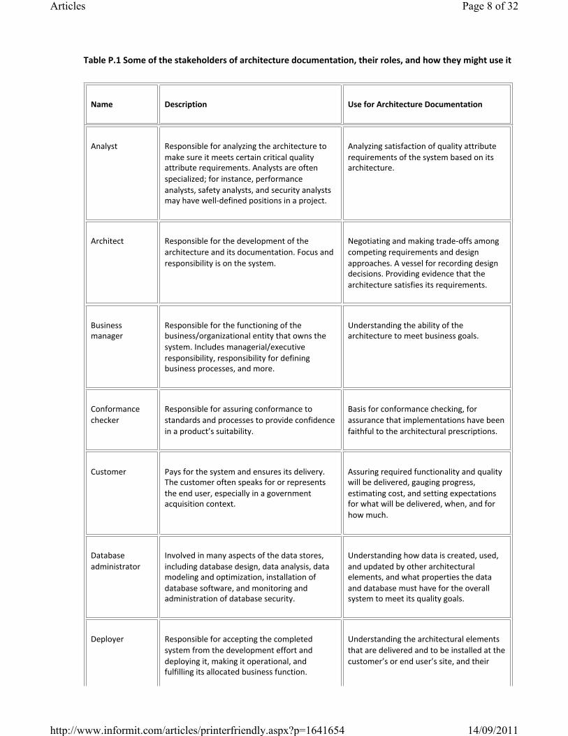
Table P.1 Some of the stakeholders of architecture documentation, their roles, and how they might use it
Name Description Use for Architecture Documentation
Analyst Responsible for analyzing the architecture to make sure it meets certain critical quality attribute requirements. Analysts are often specialized; for instance, performance analysts, safety analysts, and security analysts may have welldefined positions in a project.
Analyzing satisfaction of quality attribute requirements of the system based on its architecture.
Architect Responsible for the development of the architecture and its documentation. Focus and responsibility is on the system.
Negotiating and making tradeoffs among competing requirements and design approaches. A vessel for recording design decisions. Providing evidence that the architecture satisfies its requirements.
Business manager
Responsible for the functioning of the business/organizational entity that owns the system. Includes managerial/executive responsibility, responsibility for defining business processes, and more.
Understanding the ability of the architecture to meet business goals.
Conformance checker
Responsible for assuring conformance to standards and processes to provide confidence in a product’s suitability.
Basis for conformance checking, for assurance that implementations have been faithful to the architectural prescriptions.
Customer Pays for the system and ensures its delivery. The customer often speaks for or represents the end user, especially in a government acquisition context.
Assuring required functionality and quality will be delivered, gauging progress, estimating cost, and setting expectations for what will be delivered, when, and for how much.
Database administrator
Involved in many aspects of the data stores, including database design, data analysis, data modeling and optimization, installation of database software, and monitoring and administration of database security.
Understanding how data is created, used, and updated by other architectural elements, and what properties the data and database must have for the overall system to meet its quality goals.
Deployer Responsible for accepting the completed system from the development effort and deploying it, making it operational, and fulfilling its allocated business function.
Understanding the architectural elements that are delivered and to be installed at the customer’s or end user’s site, and their
Page 8 of 32Articles
14/09/2011http://www.informit.com/articles/printerfriendly.aspx?p=1641654
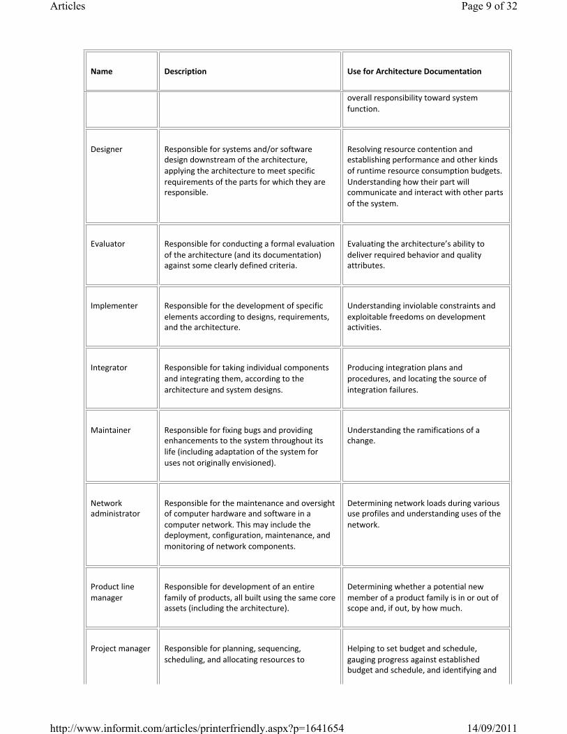
Name Description Use for Architecture Documentation
overall responsibility toward system function.
Designer Responsible for systems and/or software design downstream of the architecture, applying the architecture to meet specific requirements of the parts for which they are responsible.
Resolving resource contention and establishing performance and other kinds of runtime resource consumption budgets. Understanding how their part will communicate and interact with other parts of the system.
Evaluator Responsible for conducting a formal evaluation of the architecture (and its documentation) against some clearly defined criteria.
Evaluating the architecture’s ability to deliver required behavior and quality attributes.
Implementer Responsible for the development of specific elements according to designs, requirements, and the architecture.
Understanding inviolable constraints and exploitable freedoms on development activities.
Integrator Responsible for taking individual components and integrating them, according to the architecture and system designs.
Producing integration plans and procedures, and locating the source of integration failures.
Maintainer Responsible for fixing bugs and providing enhancements to the system throughout its life (including adaptation of the system for uses not originally envisioned).
Understanding the ramifications of a change.
Network administrator
Responsible for the maintenance and oversight of computer hardware and software in a computer network. This may include the deployment, configuration, maintenance, and monitoring of network components.
Determining network loads during various use profiles and understanding uses of the network.
Product line manager
Responsible for development of an entire family of products, all built using the same core assets (including the architecture).
Determining whether a potential new member of a product family is in or out of scope and, if out, by how much.
Project manager Responsible for planning, sequencing, scheduling, and allocating resources to
Helping to set budget and schedule, gauging progress against established budget and schedule, and identifying and
Page 9 of 32Articles
14/09/2011http://www.informit.com/articles/printerfriendly.aspx?p=1641654
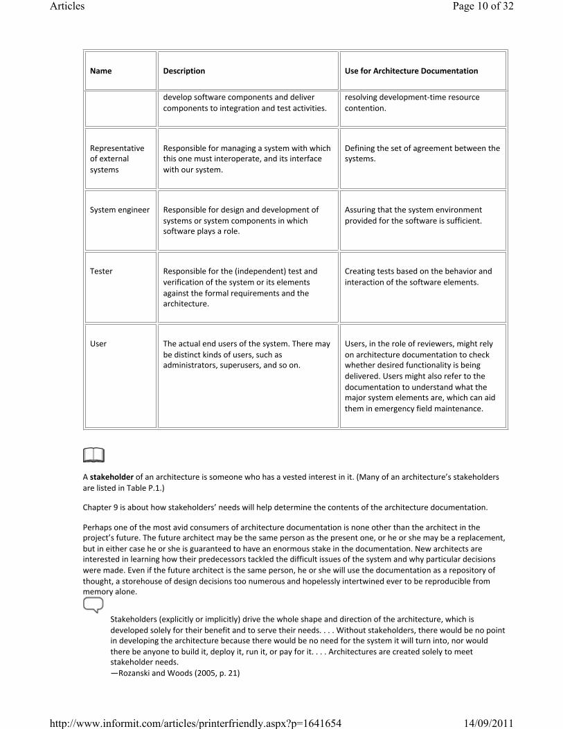
Name Description Use for Architecture Documentation
develop software components and deliver components to integration and test activities.
resolving developmenttime resource contention.
Representative of external systems
Responsible for managing a system with which this one must interoperate, and its interface with our system.
Defining the set of agreement between the systems.
System engineer Responsible for design and development of systems or system components in which software plays a role.
Assuring that the system environment provided for the software is sufficient.
Tester Responsible for the (independent) test and verification of the system or its elements against the formal requirements and the architecture.
Creating tests based on the behavior and interaction of the software elements.
User The actual end users of the system. There may be distinct kinds of users, such as administrators, superusers, and so on.
Users, in the role of reviewers, might rely on architecture documentation to check whether desired functionality is being delivered. Users might also refer to the documentation to understand what the major system elements are, which can aid them in emergency field maintenance.
A stakeholder of an architecture is someone who has a vested interest in it. (Many of an architecture’s stakeholders are listed in Table P.1.)
Chapter 9 is about how stakeholders’ needs will help determine the contents of the architecture documentation.
Perhaps one of the most avid consumers of architecture documentation is none other than the architect in the project’s future. The future architect may be the same person as the present one, or he or she may be a replacement, but in either case he or she is guaranteed to have an enormous stake in the documentation. New architects are interested in learning how their predecessors tackled the difficult issues of the system and why particular decisions were made. Even if the future architect is the same person, he or she will use the documentation as a repository of thought, a storehouse of design decisions too numerous and hopelessly intertwined ever to be reproducible from memory alone.
Stakeholders (explicitly or implicitly) drive the whole shape and direction of the architecture, which is developed solely for their benefit and to serve their needs. . . . Without stakeholders, there would be no point in developing the architecture because there would be no need for the system it will turn into, nor would there be anyone to build it, deploy it, run it, or pay for it. . . . Architectures are created solely to meet stakeholder needs. —Rozanski and Woods (2005, p. 21)
Page 10 of 32Articles
14/09/2011http://www.informit.com/articles/printerfriendly.aspx?p=1641654
Even in the short term, documenting an architecture helps in the process of designing the architecture. First, the documentation provides dedicated compartments for recording various kinds of design decisions as soon as they are made. Second, the documentation gives you a rough but helpful way to gauge progress and the work remaining: As “TBD”s disappear from the document, completion draws near. Finally, documentation provides a framework for systematic attack on designing the architecture. Key design decisions, usually made early, should be written down so that the shadow they cast on subsequent design decisions is explicit and remembered.
Quote
In our organization, a development group writes design documents to communicate with other developers, external test organizations, performance analysts, the technical writers of manuals and product helps, the separate installation package developers, the usability team, and the people who manage translation testing for internationalization. Each of these groups has specific questions in mind that are very different from the ones that other groups ask:
◦ What test cases will be needed to flush out functional errors?◦ Where is this design likely to break down?◦ Can the design be made easier to test?◦ How will this design affect the response of the system to heavy loads?◦ Are there aspects of this design that will affect its performance or ability to scale to many users?◦ What information will users or administrators need to use this system, and can I imagine writing it from the
information in this design? ◦ Does this design require users to answer configuration questions that they won’t know how to answer?◦ Does it create restrictions that users will find onerous?◦ How much translatable text will this design require?◦ Does the design account for the problems of dealing with doublebyte character sets or bidirectional
presentation?
—Kathryn Heninger Britton (Hoffman and Weiss 2001, pp. 337–338)
3. Architecture serves as the basis for system analysis and construction. ◦ Architecture tells implementers what to implement.◦ For those interested in the ability of the design to meet the system’s quality objectives, the architecture
documentation serves as the fodder for evaluation. The architecture documentation must contain the information necessary to evaluate a variety of attributes, such as security, performance, usability, availability, and modifiability. Analyses of each one of these attributes have their own information needs.
◦ For system builders who use automatic codegeneration tools, the documentation may incorporate the models used for generation.
Get the habit of analysis—analysis will in time enable synthesis to become your habit of mind.—Frank Lloyd Wright
P.2.3 Architecture Documentation and Quality Attributes
If architecture is largely about the achievement of quality attributes, and if one of the main uses of architecture documentation is to serve as a basis for analysis (to make sure the architecture will achieve its required quality attributes), where do quality attributes show up in the documentation? There are five major ways:
1. Any major design approach (such as an architecture pattern or style) chosen by the architect will have quality attribute properties associated with it. Clientserver is good for scalability, layering is good for portability, an informationhidingbased decomposition is good for modifiability, services are good for interoperability, and so forth. Explaining the choice of approach is likely to include a discussion about the satisfaction of quality attribute requirements and tradeoffs incurred. Look for the place in the documentation where such an explanation occurs. In our approach, we call that rationale.
Page 11 of 32Articles
14/09/2011http://www.informit.com/articles/printerfriendly.aspx?p=1641654
For more on styles and patterns, see “Coming to Terms: ‘Architecture Style’ and ‘Architecture Pattern’” on page 32, in this chapter.
Documenting rationale is covered in Section 6.5.
2. Individual architectural elements that provide a service often have quality attribute bounds assigned to them. Consumers of the services need to know how fast, secure, or reliable those services are. These quality attribute bounds are defined in the interface documentation for the elements, sometimes in the form of a Quality of Service contract. Or they may simply be recorded as properties that the elements exhibit.
Interface documentation is covered in Chapter 7.
Properties are discussed in Section I.3, in the introduction to Part I.
3. Quality attributes often impart a “language” of things that you would look for. Security involves things like security levels, authenticated users, audit trails, firewalls, and the like. Performance brings to mind buffer capacities, deadlines, periods, event rates and distributions, clocks and timers, and so on. Availability conjures up mean time between failure, failover mechanisms, primary and secondary functionality, critical and noncritical processes, and redundant elements. Someone fluent in the “language” of a quality attribute can search for the kinds of architectural elements (and properties of those elements) that were put in place precisely to satisfy that quality attribute requirement.
4. Architecture documentation often contains a mapping to requirements that shows how requirements (including quality attribute requirements) are satisfied. If your requirements document establishes a requirement for availability, for instance, then you should be able to look up that requirement by name or reference in your architecture document to see the place(s) where that requirement is satisfied.
Documenting a mapping to requirements is covered in Section 10.3.
5. Every quality attribute requirement will have a constituency of stakeholders who want to know that that quality attribute requirement is going to be satisfied. For these stakeholders, the architect should provide a special place in the documentation’s introduction that either provides what the stakeholder is looking for or tells the stakeholder where in the document to find it. It would say something like “If you are a performance analyst, you should pay attention to the processes and threads and their properties (defined [here]), and their deployment on the underlying hardware platform (defined [here]).” In our documentation approach, we put this here’swhatyou’relookingfor information in a section called the documentation roadmap.
The documentation roadmap is described in Section 10.2.
P.2.4 Economics of Architecture Documentation
We’d all like to make our stakeholders happy, of course. Giddy, in fact. So why is producing highquality architecture documentation often relegated to the “I’ll do it if I have time” category of an architect’s many tasks? Why do project managers often fail to insist that architecture documentation accompany the other archival artifacts produced during development? The answer, of course, is that an architecture document, let alone one that induces giddiness, costs time and money.
The man who stops advertising to save money is like the man who stops the clock to save time. [The same could be said for the architect who stops documenting.] —Thomas Jefferson
Page 12 of 32Articles
14/09/2011http://www.informit.com/articles/printerfriendly.aspx?p=1641654
Project managers are, by and large, rational people. (No, seriously, they are.) They are willing to invest resources in activities that yield demonstrable benefit, and not so much otherwise. As architects, we should be able to make a business case for producing and maintaining architecture documentation. And here it is: Activities that the project manager is going to have to fund will be less costly in the presence of highquality, uptodate documentation than they would otherwise.
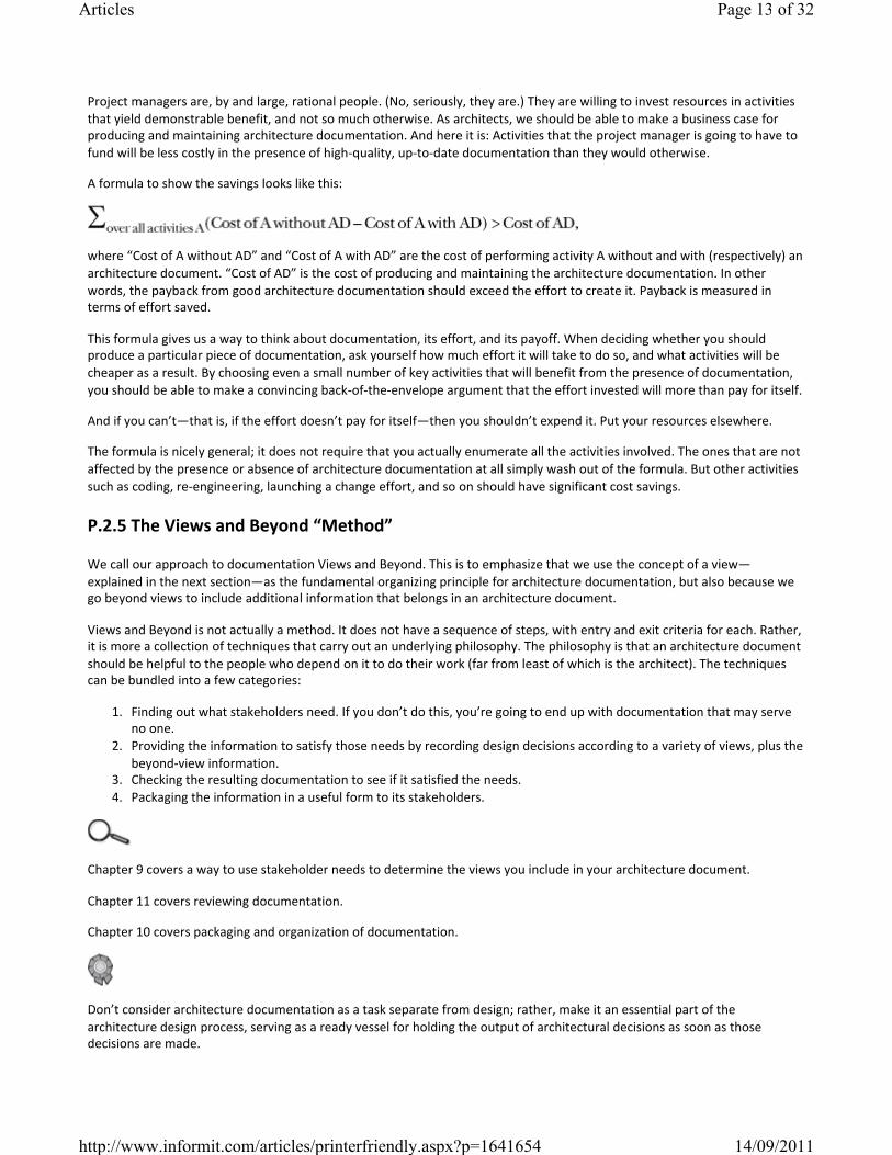
A formula to show the savings looks like this:
where “Cost of A without AD” and “Cost of A with AD” are the cost of performing activity A without and with (respectively) an architecture document. “Cost of AD” is the cost of producing and maintaining the architecture documentation. In other words, the payback from good architecture documentation should exceed the effort to create it. Payback is measured in terms of effort saved.
This formula gives us a way to think about documentation, its effort, and its payoff. When deciding whether you should produce a particular piece of documentation, ask yourself how much effort it will take to do so, and what activities will be cheaper as a result. By choosing even a small number of key activities that will benefit from the presence of documentation, you should be able to make a convincing backoftheenvelope argument that the effort invested will more than pay for itself.
And if you can’t—that is, if the effort doesn’t pay for itself—then you shouldn’t expend it. Put your resources elsewhere.
The formula is nicely general; it does not require that you actually enumerate all the activities involved. The ones that are not affected by the presence or absence of architecture documentation at all simply wash out of the formula. But other activities such as coding, reengineering, launching a change effort, and so on should have significant cost savings.
P.2.5 The Views and Beyond “Method”
We call our approach to documentation Views and Beyond. This is to emphasize that we use the concept of a view—explained in the next section—as the fundamental organizing principle for architecture documentation, but also because we go beyond views to include additional information that belongs in an architecture document.
Views and Beyond is not actually a method. It does not have a sequence of steps, with entry and exit criteria for each. Rather, it is more a collection of techniques that carry out an underlying philosophy. The philosophy is that an architecture document should be helpful to the people who depend on it to do their work (far from least of which is the architect). The techniques can be bundled into a few categories:
1. Finding out what stakeholders need. If you don’t do this, you’re going to end up with documentation that may serve no one.
2. Providing the information to satisfy those needs by recording design decisions according to a variety of views, plus the beyondview information.
3. Checking the resulting documentation to see if it satisfied the needs.4. Packaging the information in a useful form to its stakeholders.
Chapter 9 covers a way to use stakeholder needs to determine the views you include in your architecture document.
Chapter 11 covers reviewing documentation.
Chapter 10 covers packaging and organization of documentation.
Don’t consider architecture documentation as a task separate from design; rather, make it an essential part of the architecture design process, serving as a ready vessel for holding the output of architectural decisions as soon as those decisions are made.
Page 13 of 32Articles
14/09/2011http://www.informit.com/articles/printerfriendly.aspx?p=1641654
While items 3 and 4 denote documentcentric activities, items 1 and 2 denote activities that should be carried out in conjunction with performing the architecture design. That is, we don’t want Views and Beyond to be an architecture documentation method; rather, we want it to help the architect identify and record the necessary design decisions as they are made. Documentation should be the helpful result of making an architecture decision, not a separate step in the architecture process. The more that documentation is treated like a followon to design, with its own separate method, the less likely it is to be done at all.
P.2.6 Views and Beyond in an Agile Environment
It is an unfortunate myth that Agile development and documentation (particularly architecture documentation) are at odds with each other. They aren’t, and there are many examples of Agile leaders saying exactly that. Nevertheless, it is possible to interpret the advice in this book as prescribing a heavyweight and cumbersome approach to documentation. You can imagine an architect lagging hopelessly behind the project, which has gone on to deliver the product while he or she is still struggling to complete a ViewsandBeyondstyle documentation package from six iterations ago. Neither the architect (nor this book) would likely be invited back to the next project.
[W]e have come to value . . . working software over comprehensive documentation.—The Agile Manifesto (Agile Alliance 2002)
Section E.4 in the epilogue elaborates on architecture documentation in an Agile environment.
Here is some advice that applies to all projects but especially to Agile projects: The Views and Beyond approach provides guidance for documenting many kinds of architecture information: structures, elements, relations, behavior, interfaces, rationale, traces to requirements, style guides, system context, and a whole lot more. But nowhere is it written that you have to do all of that. Decide what is useful (you can use the formula in Section P.2.4 to help you decide). Then, for example, if you decide that documenting the rationale behind a certain design decision is going to pay off in the future, then you can use the available guidance to help you do it. If you decide that documenting certain views is useful, then you can use the available guidance to help you do it. And so forth.
Choose what’s useful and costeffective to document. Document that. Period.
P.2.7 Architectures That Change Faster Than You Can Document Them
When your Web browser encounters a file type it’s never seen before, odds are that it will go to the Internet, download the appropriate plugin to handle the file, install it, and reconfigure itself to use it. Without even needing to shut down, let alone go through the codeintegratetest development cycle, the browser is able to change its own architecture by adding a new component.
Serviceoriented systems that utilize dynamic service discovery and binding also exhibit these properties. More challenging systems that are highly dynamic, selforganizing, and reflective (meaning selfaware) are on the horizon. In these cases, the identities of the components interacting with each other cannot be pinned down, let alone their interactions, in any static architecture document.
Another kind of architectural dynamism, equally challenging from a documentation perspective, is found in systems that are rebuilt and redeployed with great rapidity. Some development shops, such as those responsible for commercial Web sites, build and “go live” with their system many dozens of times every single day.
Whether an architecture changes at runtime, or as a result of a highfrequency releaseanddeploy cycle, both share something in common with respect to documentation: They change much faster than the documentation cycle. In either case, nobody is going to hold up things until a new architecture document is produced, reviewed, and released.
But knowing the architecture of these systems is every bit as important, and arguably more so, than for systems in the world of more traditional life cycles. Here’s what you can do if you’re an architect in a highly dynamic environment:
Page 14 of 32Articles
14/09/2011http://www.informit.com/articles/printerfriendly.aspx?p=1641654
1. Document what is true about all versions of your system. Your Web browser doesn’t go out and grab just any piece of software when it needs a new plugin; a plugin must have specific properties and a specific interface. And it doesn’t just plug in anywhere, but in a predetermined location in the architecture. Record those invariants as you would for any architecture. This may make your documented architecture more a description of constraints or guidelines that any compliant version of the system must follow. That’s fine.
2. Document the ways the architecture is allowed to change. In the previous examples, this will usually mean adding new components and/or replacing components with new implementations. In the Views and Beyond approach, the place to do this is called the variability guide.
Using a variability guide to document an architecture’s variation points is covered in Section 6.4.
3. Make your system capture its own architectureofthemoment automatically. When your Web browser or SOA system crashes, your recovery team is going to want to know exactly what configuration was running when the problem occurred. This ability can run the spectrum from primitive (write changes in a log file) to sophisticated (drive a realtime display of the components and their interactions, much like what is found in network service centers).
P.3 Architecture Views
Perhaps the most important concept associated with software architecture documentation is that of the view. A software architecture is a complex entity that cannot be described in a simple onedimensional fashion. Our analogy with the bird wing proves illuminating. If you are interested in any but the most superficial understanding, then no single rendition of a bird wing will do. Instead, you need many: feathers, skeleton, circulation, muscular views, and many others. Which of these views is the “architecture” of the wing? None of them. Which views convey the architecture? All of them.
A view is a representation of a set of system elements and the relationships associated with them.
For more information about the bird wing analogy, see “About the Cover” on page xxi.
In this book, we use the concept of views to give us the most fundamental principle of architecture documentation, illustrated in Figure P.1:
Documenting an architecture is a matter of documenting the relevant views and then adding documentation that applies to more than one view.
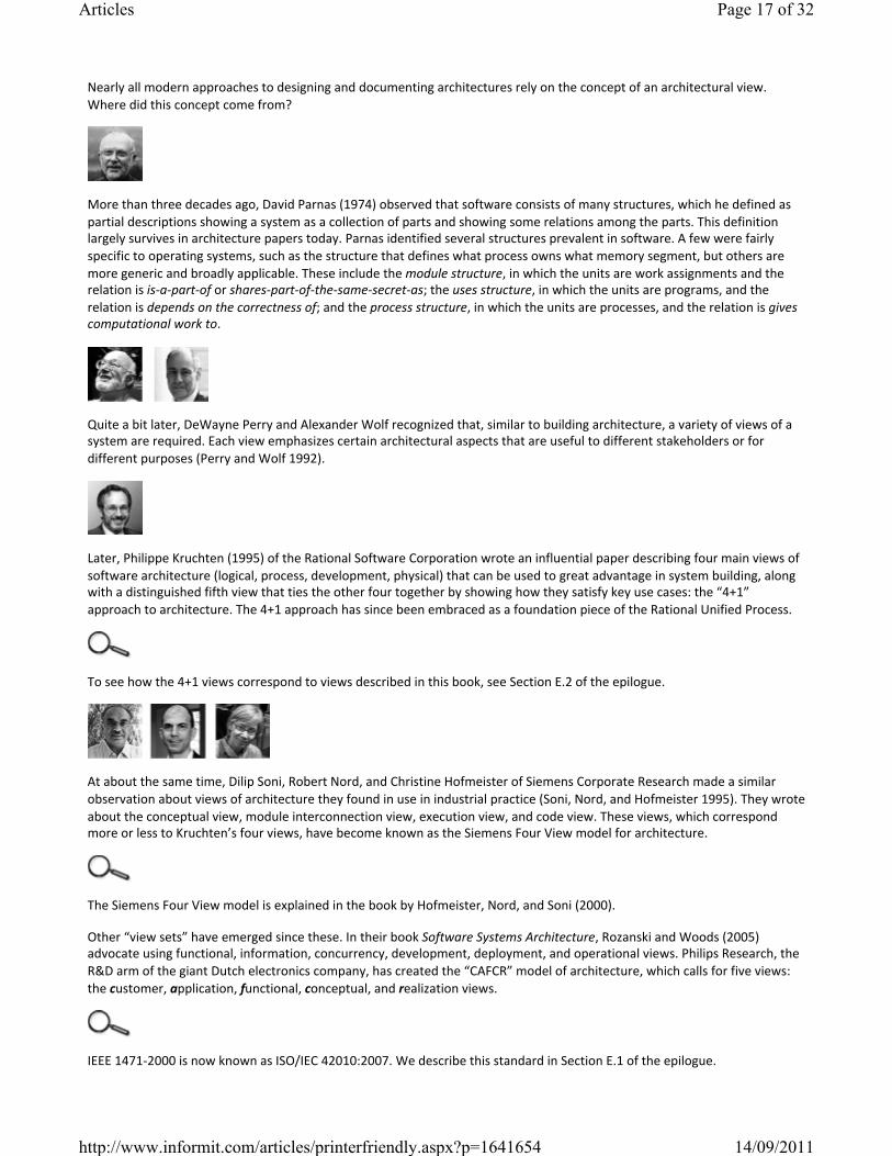
Figure P.1 A documentation package for a software architecture can be composed of one or more view documents and documentation that explains how the views relate to one another, introduces the package to its readers, and guides them through it.
What are the relevant views? It depends on your goals. As we saw previously, architecture documentation can serve many purposes: a mission statement for implementers, a basis for analysis, the specification for automatic code generation, the starting point for system understanding and asset recovery, or the blueprint for project planning.
Chapter 9 shows how to choose the relevant views. Section 10.1 shows how to document a view, and Section 10.2 shows how to document the information that applies to more than one view.
Page 15 of 32Articles
14/09/2011http://www.informit.com/articles/printerfriendly.aspx?p=1641654
Different views also expose different quality attributes to different degrees. Therefore, the quality attributes that are of most concern to you and the other stakeholders in the system’s development will affect the choice of what views to document. For instance, a layered view will tell you about your system’s portability, a deployment view will let you reason about your system’s performance and reliability, and so forth.
Layered views are covered in Section 2.4. Deployment views are covered in Section 5.2.
Different views support different goals and uses. This is fundamentally why we do not advocate a particular view or collection of views. The views you should document depend on the uses you expect to make of the documentation. Different views will highlight different system elements and/or relations.
It may be disconcerting that no single view can fully represent an architecture. Additionally, it feels somehow inadequate to see the system only through discrete, multiple views that may or may not relate to one another in any straightforward way. The essence of architecture is the suppression of information not necessary to the task at hand, and so it is somehow fitting that the very nature of architecture is such that it never presents its whole self to us but only a facet or two at a time. This is its strength: Each view emphasizes certain aspects of the system while deemphasizing or ignoring other aspects, all in the interest of making the problem at hand tractable. Nevertheless, no one of these individual views adequately documents the software architecture for the system. That is accomplished by the complete set of views along with information that transcends them.
An objectoriented program’s runtime structure often bears little resemblance to its code structure. The code structure is frozen at compiletime; it consists of classes in fixed inheritance relationships. A program’s runtime structure consists of rapidly changing networks of communicating objects. In fact, the two structures are largely independent. Trying to understand one from the other is like trying to understand the dynamism of living ecosystems from the static taxonomy of plants and animals, and vice versa.—Gamma et al. (1995, p. 22)
The documentation for a view contains
• A primary presentation, usually graphical, that depicts the primary elements and relations of the view• An element catalog that explains and defines the elements shown in the view and lists their properties• A specification of the elements’ interfaces and behavior• A variability guide explaining any builtin mechanisms available for tailoring the architecture
Section 10.1 substantially elaborates this outline.
• Rationale and design information
The documentation that applies to all of the views contains
• An introduction to the entire package, including a reader’s guide that helps a stakeholder find a desired piece of information quickly
Section 10.2 substantially elaborates this outline.
• Information describing how the views relate to one another, and to the system as a whole• Constraints and rationale for the overall architecture• Such management information as may be required to effectively maintain the whole package
Coming To Terms: A Short History of Architecture Views
Page 16 of 32Articles
14/09/2011http://www.informit.com/articles/printerfriendly.aspx?p=1641654
Nearly all modern approaches to designing and documenting architectures rely on the concept of an architectural view. Where did this concept come from?
More than three decades ago, David Parnas (1974) observed that software consists of many structures, which he defined as partial descriptions showing a system as a collection of parts and showing some relations among the parts. This definition largely survives in architecture papers today. Parnas identified several structures prevalent in software. A few were fairly specific to operating systems, such as the structure that defines what process owns what memory segment, but others are more generic and broadly applicable. These include the module structure, in which the units are work assignments and the relation is is-a-part-of or shares-part-of-the-same-secret-as; the uses structure, in which the units are programs, and the relation is depends on the correctness of; and the process structure, in which the units are processes, and the relation is gives computational work to.
Quite a bit later, DeWayne Perry and Alexander Wolf recognized that, similar to building architecture, a variety of views of a system are required. Each view emphasizes certain architectural aspects that are useful to different stakeholders or for different purposes (Perry and Wolf 1992).
Later, Philippe Kruchten (1995) of the Rational Software Corporation wrote an influential paper describing four main views of software architecture (logical, process, development, physical) that can be used to great advantage in system building, along with a distinguished fifth view that ties the other four together by showing how they satisfy key use cases: the “4+1” approach to architecture. The 4+1 approach has since been embraced as a foundation piece of the Rational Unified Process.
To see how the 4+1 views correspond to views described in this book, see Section E.2 of the epilogue.
At about the same time, Dilip Soni, Robert Nord, and Christine Hofmeister of Siemens Corporate Research made a similar observation about views of architecture they found in use in industrial practice (Soni, Nord, and Hofmeister 1995). They wrote about the conceptual view, module interconnection view, execution view, and code view. These views, which correspond more or less to Kruchten’s four views, have become known as the Siemens Four View model for architecture.
The Siemens Four View model is explained in the book by Hofmeister, Nord, and Soni (2000).
Other “view sets” have emerged since these. In their book Software Systems Architecture, Rozanski and Woods (2005) advocate using functional, information, concurrency, development, deployment, and operational views. Philips Research, the R&D arm of the giant Dutch electronics company, has created the “CAFCR” model of architecture, which calls for five views: the customer, application, functional, conceptual, and realization views.
IEEE 14712000 is now known as ISO/IEC 42010:2007. We describe this standard in Section E.1 of the epilogue.
Page 17 of 32Articles
14/09/2011http://www.informit.com/articles/printerfriendly.aspx?p=1641654
In the year 2000, the IEEE adopted a standard (IEEE 14712000) for architecture descriptions. Unlike approaches that prescribe a fixed set of views, this standard advocates creating your own views that best serve the stakeholders and their concerns associated with your system. (The Views and Beyond approach also advises flexibility in choosing your view set.)
P.4 Architecture Styles
Recurring forms have been widely observed, even if written for completely different systems. These forms occur often enough that they are worth writing and learning about in their own right. We call these forms architecture styles. (In this book, we usually just say styles.) Styles have implications for architecture documentation and deserve definition and discussion in their own right.
An architecture style is a specialization of element and relation types, together with a set of constraints on how they can be used.
Styles allow one to apply specialized design knowledge to a particular class of systems and to support that class of system design with stylespecific tools, analysis, and implementations. The literature is replete with a number of styles, and most architects have a wide selection in their repertoires.
For example, we’ll see that modules can be arranged into a useful configuration by restricting what each one is allowed to use. The result is a layered style that imparts to systems that use it qualities of modifiability and portability. Different systems will have a different number of layers, different contents in each layer, and different rules for what each layer is allowed to use. However, the layered style is abstract with respect to these options and can be studied and analyzed without binding them.
In all processes of life people imitate, and so must artists. They are influenced by their peers as by their antecedents because this is the way of organic development. Late Beethoven and early Schubert, for instance, are almost indistinguishable; while Brahms took certain themes, note for note, from Beethoven; and Shakespeare stole nearly all of his plots—all the good ones certainly.—Agnes de Mille, American dancer and choreographer (Atlantic 1956)
For another example, we’ll see that clientserver is a common architecture style. The elements in this style are clients, servers, and the protocol connectors that depict their interaction. When used in a system, the clientserver style imparts desirable properties to the system, such as the ability to add clients with little effort. Different systems will have different protocols, different numbers of servers, and different numbers of clients each can support. However, the clientserver style is abstract with respect to these options and can be studied and analyzed without binding them.
The layered style is described in Section 2.4.
The clientserver style is described in Section 4.3.1.
Some styles are applicable in every software system. For example, every system is decomposed into modules to divide the work; hence, the decomposition style applies everywhere. Other examples of “universal styles” are uses, deployment, and work assignment. Some styles occur only in systems in which they were explicitly chosen and designed in by the architect: layered, service oriented, and multitier, for example.
A style guide is the description of an architecture style that specifies the vocabulary of design (sets of element and relationship types) and the rules (sets of topological and semantic constraints) for how that vocabulary can be used.
Page 18 of 32Articles
14/09/2011http://www.informit.com/articles/printerfriendly.aspx?p=1641654
The contents of a style guide are given in Section I.2, in the introduction to Part I. Section 6.1.4 discusses how to create and document a new style.
Choosing a style, whether it’s one covered in this book or somewhere else, imparts a documentation obligation to record the specializations and constraints that the style imposes and the characteristics that the style imparts to the system. We call this piece of documentation a style guide. The obligation to document a style can usually be discharged by citing a description of the style in the literature: this book, for example. If you invent your own style, however, you should write a style guide for it because it will help you and your peers to apply that style in other systems.
No system is built exclusively from a single style. On the contrary, every system can be seen to be an amalgamation of many different styles. Some (such as decomposition and work assignment) occur in every system, but in addition to these, systems can exhibit a combination of one or more “chosen” styles as well.
Combining views is an important concept covered in Section 6.6.
Even restricting our attention to componentandconnector styles, it’s possible for one system to exhibit several styles in the following ways:
A bridging element is an element that is common to two views and is used to provide the continuity of understanding from one view to the other. A bridging element appears in both views and has supporting documentation, usually a mapping between views, that makes the correspondence clear, perhaps by showing the combined picture.
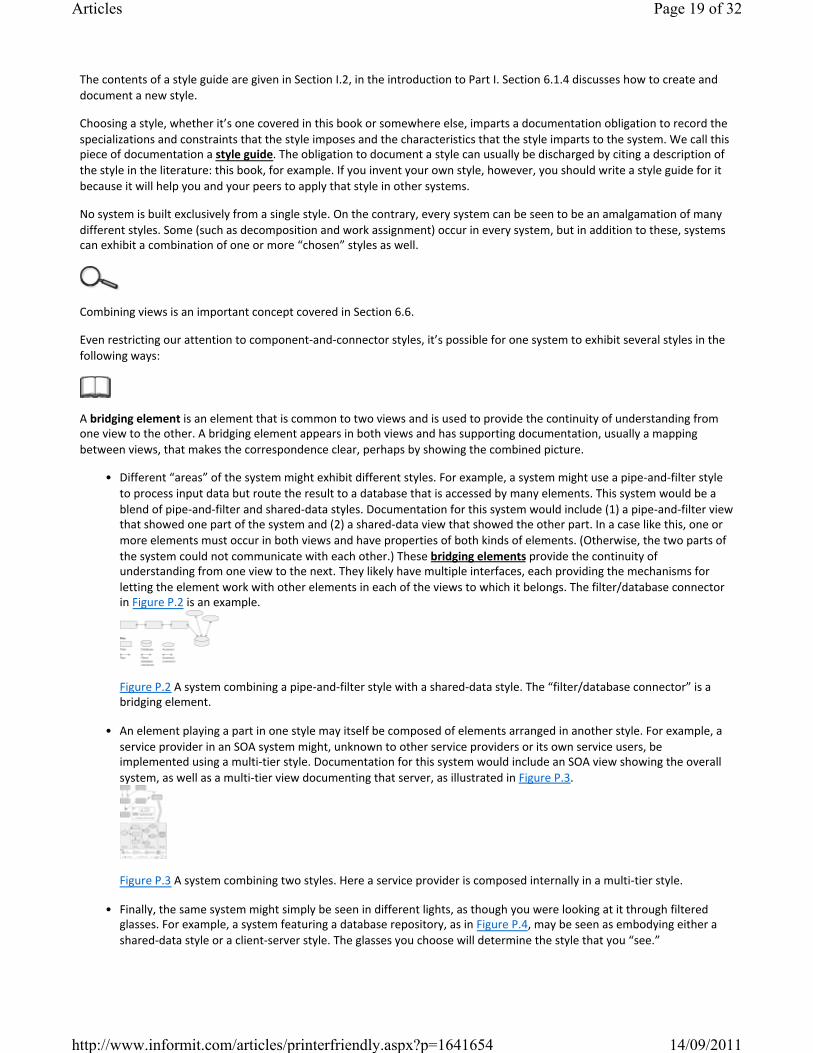
• Different “areas” of the system might exhibit different styles. For example, a system might use a pipeandfilter style to process input data but route the result to a database that is accessed by many elements. This system would be a blend of pipeandfilter and shareddata styles. Documentation for this system would include (1) a pipeandfilter view that showed one part of the system and (2) a shareddata view that showed the other part. In a case like this, one or more elements must occur in both views and have properties of both kinds of elements. (Otherwise, the two parts of the system could not communicate with each other.) These bridging elements provide the continuity of understanding from one view to the next. They likely have multiple interfaces, each providing the mechanisms for letting the element work with other elements in each of the views to which it belongs. The filter/database connector in Figure P.2 is an example.
Figure P.2 A system combining a pipeandfilter style with a shareddata style. The “filter/database connector” is a bridging element.
• An element playing a part in one style may itself be composed of elements arranged in another style. For example, a service provider in an SOA system might, unknown to other service providers or its own service users, be implemented using a multitier style. Documentation for this system would include an SOA view showing the overall system, as well as a multitier view documenting that server, as illustrated in Figure P.3.
Figure P.3 A system combining two styles. Here a service provider is composed internally in a multitier style.
• Finally, the same system might simply be seen in different lights, as though you were looking at it through filtered glasses. For example, a system featuring a database repository, as in Figure P.4, may be seen as embodying either a shareddata style or a clientserver style. The glasses you choose will determine the style that you “see.”
Page 19 of 32Articles
14/09/2011http://www.informit.com/articles/printerfriendly.aspx?p=1641654
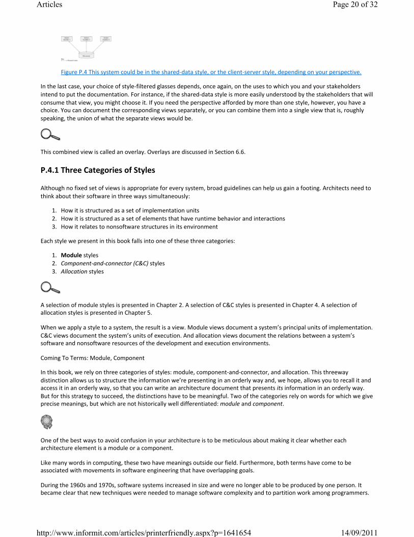
Figure P.4 This system could be in the shareddata style, or the clientserver style, depending on your perspective.
In the last case, your choice of stylefiltered glasses depends, once again, on the uses to which you and your stakeholders intend to put the documentation. For instance, if the shareddata style is more easily understood by the stakeholders that will consume that view, you might choose it. If you need the perspective afforded by more than one style, however, you have a choice. You can document the corresponding views separately, or you can combine them into a single view that is, roughly speaking, the union of what the separate views would be.
This combined view is called an overlay. Overlays are discussed in Section 6.6.
P.4.1 Three Categories of Styles
Although no fixed set of views is appropriate for every system, broad guidelines can help us gain a footing. Architects need to think about their software in three ways simultaneously:
1. How it is structured as a set of implementation units2. How it is structured as a set of elements that have runtime behavior and interactions3. How it relates to nonsoftware structures in its environment
Each style we present in this book falls into one of these three categories:
1. Module styles 2. Component-and-connector (C&C) styles 3. Allocation styles
A selection of module styles is presented in Chapter 2. A selection of C&C styles is presented in Chapter 4. A selection of allocation styles is presented in Chapter 5.
When we apply a style to a system, the result is a view. Module views document a system’s principal units of implementation. C&C views document the system’s units of execution. And allocation views document the relations between a system’s software and nonsoftware resources of the development and execution environments.
Coming To Terms: Module, Component
In this book, we rely on three categories of styles: module, componentandconnector, and allocation. This threeway distinction allows us to structure the information we’re presenting in an orderly way and, we hope, allows you to recall it and access it in an orderly way, so that you can write an architecture document that presents its information in an orderly way. But for this strategy to succeed, the distinctions have to be meaningful. Two of the categories rely on words for which we give precise meanings, but which are not historically well differentiated: module and component.
One of the best ways to avoid confusion in your architecture is to be meticulous about making it clear whether each architecture element is a module or a component.
Like many words in computing, these two have meanings outside our field. Furthermore, both terms have come to be associated with movements in software engineering that have overlapping goals.
During the 1960s and 1970s, software systems increased in size and were no longer able to be produced by one person. It became clear that new techniques were needed to manage software complexity and to partition work among programmers.
Page 20 of 32Articles
14/09/2011http://www.informit.com/articles/printerfriendly.aspx?p=1641654

To address such issues of “programming in the large,” various criteria were introduced to help programmers decide how to partition their software. Encapsulation, information hiding, and abstract data types became the dominant design paradigms of the day. Until this movement, computer programs were largely about calculating the correct answer, but thought leaders were now saying that how you structure your code determines other important properties of the system. Module became the carrier of their meaning. The 1970s and 1980s saw the advent of “module interconnection languages” and features of new programming languages such as Modula modules, Smalltalk classes, and Ada packages. Today’s dominant design paradigm—objectoriented programming—has these module concepts at its heart. Components, by contrast, are in the limelight with componentbased software engineering and the componentandconnector perspective in the software architecture field.
Both movements aspire to achieve rapid system construction and evolution through the selection, assembly, and wholesale replacement of independent subpieces. Both modules and components are about the decomposition of a whole software system into constituent parts. But beyond that, the two terms take on different shades of meaning.
• A module refers first and foremost to a unit of implementation. Parnas’s foundational work in module design (Parnas 1972) used information hiding as the criterion for allocating responsibility to a module. Information that was likely to change over the lifetime of a system, such as the choice of data structures or algorithms, was assigned to a module, which had an interface through which its facilities were accessed. Modules have long been associated with source code, but information models, XML files, config files, BNF files for parsers, and other implementation artifacts are all perfectly fine modules.
• A component refers to a runtime entity. Szyperski says that a component “can be deployed independently and is subject to composition by third parties” (Szyperski 1998, p. 30). The emphasis is clearly on the finished product and not on the implementation considerations that went into it. Indeed, the operative model is that a component is delivered in the form of an executable binary only: Nothing upstream from that is available to the system builder.
In short, a module suggests implementation units and artifacts, with less emphasis on the delivery medium and what goes on at runtime. A component is about units of software active at runtime with no visibility into the implementation structure.
Who cares? If every module turned into exactly one component at runtime, it would be easy to sweep the difference under the rug. But this is often far from reality! In many systems, a single module might turn into many components, or it might take many modules to turn into a single component. An easy way to see this is to imagine a trivially simple clientserver system. Suppose our system has a single server, which at runtime serves up some interesting piece of data to ten interested clients, all of which do the same thing. This system has eleven components but only two modules. The server module maps 1:1 onto the server component S1. The client module maps 1:10 to the client components C1–C10. Failing to distinguish between modules and components makes it too easy to blithely assume that every unit of implementation turns into exactly one unit of execution. It isn’t so.
Figure P.5 A clientserver system might consist of two modules but eleven components.
Our use of the terms in this book reflects their pedigrees. Module styles described in this book reflect implementation artifact considerations: decompositions that assign parts of the problem to units of design and implementation, layers that reflect what uses are allowed when software is being written, and classes that factor out commonality from a set of instances. Modules in these styles are often units of source code, but there’s also the data model style, where the module is a model of the data that the system manipulates. Of course, all these module styles have runtime implications; that’s the end game of software design, after all. C&C styles described in this book focus on how processes interact and data travels around the system during execution.
Section 10.2 describes how to document the mapping between a system’s modules and its components. Sections 1.5 and 3.5 discuss how modules and components relate to each other.
In many architectures, there is a onetoone mapping between modules and components. Further, the module and its component counterpart are usually given the same name in this case. This makes it tempting to believe that the modules and components are the same, which in turn makes it tempting to believe there is no difference. Don’t be tempted. Although a
Page 21 of 32Articles
14/09/2011http://www.informit.com/articles/printerfriendly.aspx?p=1641654
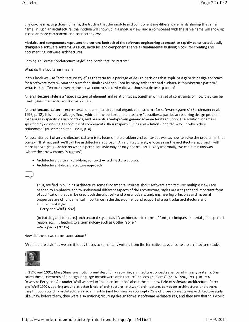
onetoone mapping does no harm, the truth is that the module and component are different elements sharing the same name. In such an architecture, the module will show up in a module view, and a component with the same name will show up in one or more componentandconnector views.
Modules and components represent the current bedrock of the software engineering approach to rapidly constructed, easily changeable software systems. As such, modules and components serve as fundamental building blocks for creating and documenting software architectures.
Coming To Terms: “Architecture Style” and “Architecture Pattern”
What do the two terms mean?
In this book we use “architecture style” as the term for a package of design decisions that explains a generic design approach for a software system. Another term for a similar concept, used by many architects and authors, is “architecture pattern.” What is the difference between these two concepts and why did we choose style over pattern?
An architecture style is a “specialization of element and relation types, together with a set of constraints on how they can be used” (Bass, Clements, and Kazman 2003).
An architecture pattern “expresses a fundamental structural organization schema for software systems” (Buschmann et al. 1996, p. 12). It is, above all, a pattern, which in the context of architecture “describes a particular recurring design problem that arises in specific design contexts, and presents a wellproven generic scheme for its solution. The solution scheme is specified by describing its constituent components, their responsibilities and relations, and the ways in which they collaborate” (Buschmann et al. 1996, p. 8).
An essential part of an architecture pattern is its focus on the problem and context as well as how to solve the problem in that context. That last part we’ll call the architecture approach. An architecture style focuses on the architecture approach, with more lightweight guidance on when a particular style may or may not be useful. Very informally, we can put it this way (where the arrow means “suggests”):
• Architecture pattern: {problem, context} → architecture approach• Architecture style: architecture approach
Thus, we find in building architecture some fundamental insights about software architecture: multiple views are needed to emphasize and to understand different aspects of the architecture; styles are a cogent and important form of codification that can be used both descriptively and prescriptively; and, engineering principles and material properties are of fundamental importance in the development and support of a particular architecture and architectural style. —Perry and Wolf (1992)
[In building architecture,] architectural styles classify architecture in terms of form, techniques, materials, time period, region, etc. . . . leading to a terminology such as Gothic “style.”—Wikipedia (2010a)
How did these two terms come about?
“Architecture style” as we use it today traces to some early writing from the formative days of software architecture study.
In 1990 and 1991, Mary Shaw was noticing and describing recurring architecture concepts she found in many systems. She called these “elements of a design language for software architecture” or “design idioms” (Shaw 1990, 1991). In 1992 Dewayne Perry and Alexander Wolf wanted to “build an intuition” about the stillnew field of software architecture (Perry and Wolf 1992). Looking around at other kinds of architecture—network architecture, computer architecture, and others—they hit upon building architecture as rich in fertile (and borrowable) concepts. One of those concepts was architecture style. Like Shaw before them, they were also noticing recurring design forms in software architectures, and they saw that this would
Page 22 of 32Articles
14/09/2011http://www.informit.com/articles/printerfriendly.aspx?p=1641654
be a useful term to appropriate to describe those forms. Styles, then, were observed phenomena, approaches (manifest in the kinds of elements and relations employed) that the authors noticed were being used over and over. The emphasis was on discovery and categorization of utilized forms.
“An architectural pattern expresses a fundamental structural organization schema for software systems. It provides a set of predefined subsystems, specifies their responsibilities, and includes rules and guidelines for organizing the relationships between them.” (Buschmann et al. 1996, p. 12)
In 1996 Frank Buschmann and his colleagues at Siemens made the inevitable connection between two powerful concepts: software architecture and design patterns (the latter having electrified software engineering the previous year). Their book, PatternOriented Software Architecture, Volume 1: A System of Patterns (Buschmann et al. 1996; PoSA, for short), is where the term architectural pattern was first used. Followed over the years by (at this writing) four sequels, the PoSA series does for architects what Design Patterns (Gamma et al. 1995) did for designers and programmers.
Both design patterns and (software) architecture patterns owe their meaning to the building architect Christopher Alexander, who in the 1970s wrote several books detailing architecture approaches to solve common building design problems. People love to sit next to windows, he wrote, so make every room have a place where they can comfortably do so. People love balconies, he wrote, but observations show they won’t spend time on a balcony less than 10 feet wide. So make your balconies at least 10 feet wide. People love outdoor spaces, he wrote, but not if they’re in the shadow of a building. So in the northern hemisphere put your courtyards on the south side. He called these design nuggets patterns: “a threepart rule, which expresses a relation between a certain context, a problem, and a solution” (Alexander 1979, p. 247). The patterns community (of whatever flavor) has tried to remain faithful to his meaning.
We must not forget that the wheel is reinvented so often because it is a very good idea; I’ve learned to worry more about the soundness of ideas that were invented only once.—D. L. Parnas (1996)
Why do patterns seem more specific?
It has turned out, not as a matter of the intrinsic nature of these things but rather as a matter of practice, that the published architecture patterns tend to be more constraining—that is, they embed more design decisions—than the published architecture styles. Patterns often look “more detailed” or “less abstract” than styles. Styles tend to tell people what the element and relation types of interest are, and give topological constraints: Put layers on top of layers; pipes connect to filters, not pipes; and so on. Patterns tend to be more specific, showing instances of the element type interacting with each other.
That’s because the collectors of styles were motivated to find commonality where none had been observed before. Broad categories are more inclusive. Pattern writers have tended to record very specific and contextdependent problems; hence their solutions are correspondingly specific.
Architects can use this de facto distinction to their advantage. For instance, if you’re handling a lot of data in your system, you might want to consider a style (the shareddata style is a good candidate) and ask yourself if the element and relation types are what you need: That is, do you really need a database? Yes? OK, now go look for a more constrained architecture approach (which might very well be given as a pattern).
Page 23 of 32Articles
14/09/2011http://www.informit.com/articles/printerfriendly.aspx?p=1641654
The shareddata style is described in Section 4.5.1.
Why did we use “architecture style” in this book?
In this book, which is about documenting software architectures and not so much about designing them, we concentrate on presenting a variety of solution approaches—architecture styles—so that we can show how to document systems built using them. In a software architecture document, one doesn’t document a pattern, one documents an application of it—that is, the instantiated solution approach.
How do I document the use of a style or pattern in a software architecture document?
Architects can use either patterns or styles as a starting point for their design. They might be published in existing catalogs, stored in an organization’s proprietary repository of standard designs, or created specifically for the problem at hand by the architect. In either case, they provide a generic (that is, incomplete) solution approach that the architect will have to refine and instantiate.
The software architecture document templates in Chapter 10 will provide a place for all of this information.
First, record the fact that the given style or pattern is being used. Then say why this solution approach was chosen—why it is a good fit to the problem at hand. If the chosen approach comes from a pattern, show that the problem at hand fits the problem and context of the pattern. If the chosen approach comes from a style, explain why the style does the needed job.
The concept of making successively more constrained design decisions is called a “spectrum of design” and is discussed in Section 6.1.3.
Using a pattern or a style means making successive design decisions that eventually result in an architecture. These design decisions manifest themselves as newly instantiated elements and relations among them. The architect can document a snapshot of the architecture at each stage. How many stages there are depends on many things, not the least of which is the ability of readers to follow the design process in case they have to revisit it in the future.
Summary
Styles are described using a common set of information; this layout is called a style guide. The style guide we use to describe the styles covered in this book is explained in the introduction to Part I.
Architecture styles represent observed architecture approaches. A style description does not generally include detailed problem/context information. Architecture patterns do. An architecture approach might be documented (and several are) as an architecture style and an architecture pattern. Both styles and patterns are a set of prepackaged design decisions involving the choice of element types, relation types, properties, and constraints on the topology and interaction among the elements via the relations. Both provide vocabularies that shortcut explanation and allow greatly facilitated communication (“My system is layered.” “Ah, I understand. What are the layers?”), and help chart a course to the satisfaction of specific quality attribute requirements. Both can be used in combination—it is a rare system that uses only one style or one architecture pattern. And both represent essential elements of an architect’s vocabulary.
These are the rules for any technical documentation, including software architecture documentation:
1. Write documentation from the reader’s point of view.2. Avoid unnecessary repetition.3. Avoid ambiguity.4. Use a standard organization.
Page 24 of 32Articles
14/09/2011http://www.informit.com/articles/printerfriendly.aspx?p=1641654
5. Record rationale.6. Keep documentation current but not too current.7. Review documentation for fitness of purpose.
P.5 Seven Rules for Sound Documentation
Architecture documentation is much like the documentation we write in other facets of our software development projects. As such, it obeys the same fundamental rules for what distinguishes good, usable documentation from poor, ignored documentation. We close the prologue with seven rules for sound software documentation. Use this checklist when you write technical documentation. (You can also use it when you read technical documentation: the rules provide objective criteria for judging a document’s quality, and they let you say something constructive in a critical review.)
Rule 1: Write Documentation from the Reader’s Point of View
The consumer isn’t a moron. She is your wife.—David Ogilvy, writing about advertising
This rule simply reminds us to keep the end game in mind as we produce our documentation: Make your document serve its stakeholders and their intended uses of it. It is surprisingly easy to forget that rule in the midst of looming deadlines, an overflowing email queue, and a cell phone that won’t shut up.
The great computing scientist Edsger Dijkstra (1930–2002), the inventor of many of the software engineering principles we now take for granted, once said that he would happily spend two hours pondering how to make a single sentence clearer. He reasoned that if the paper were read by a couple of hundred people—a decidedly modest estimate for someone of Dijkstra’s caliber—and he could save each reader a minute or two of confusion, it was well worth the effort. Professor Dijkstra’s consideration for the reader reflects his classic manners, but it also gives us a new and useful concept of the effort associated with a document. Usually we just count how long it takes to write. Dijkstra taught us to be concerned with how long it takes to use. Writing a document that a reader finds easy to use will help tilt the economics of documentation in our favor, as defined in the formula in Section P.2.4.
I have made this letter rather long only because I have not had time to make it shorter.—Blaise Pascal, French mathematician, physicist, and moralist
Writing for the reader is just plain polite, but it has a practical advantage as well. A reader who feels that the document was written with him or her in mind appreciates the effort but, more to the point, will come back to the document again and again in the future. Documents written for the reader will be read; documents written for the convenience of the writer will not. All of us like to shop at stores that seem to want our business, and we avoid stores that do not. This is no different.
Tips on how to write for the reader include:
• Find out who your readers are, what they know, and what they expect of the document. Have an informal chat with some representatives of various kinds of readers and see what their expectations are. Don’t make uninformed assumptions about what your readers know.
The true measure of a man is how he treats someone who can do him absolutely no good.—Attributed to Samuel Johnson
• Avoid stream of consciousness writing. If you find yourself writing things down in the order they occur to you, without an overall organizational plan, stop. Work out where specific kinds of information should go and put them where they belong. Make sure that you know what question(s) are being answered by each section of a document.
• Avoid unnecessary insider jargon. The documentation may be read by someone new to the field or from a company that does not share the same jargon. Add a glossary to define specialized terms.
Page 25 of 32Articles
14/09/2011http://www.informit.com/articles/printerfriendly.aspx?p=1641654

Rozanski and Woods’s book Software Systems Architecture (2005) lists the following properties of an “effective architectural description”: correctness, sufficiency, conciseness, clarity, currency, and precision.
• Avoid overuse of acronyms. Resist using an acronym when the spelledout phrase is short or it appears only a few times. Always provide a dictionary that decodes whatever acronyms you do use.
Rule 2: Avoid Unnecessary Repetition
Each kind of information should be recorded in exactly one place. This makes documentation easier to use and much easier to change as it evolves. It also avoids confusion: information that is repeated is likely to be in a slightly different form, and now the reader must wonder “Was the difference intentional? If so, what is the meaning of the difference? Did the author change one place and forget to update the other?”
It should be a goal that information never be repeated. However, at times the cost to the reader of not repeating information in the other places where it’s needed is high. Readers don’t like to flip pages or click hyperlinks unnecessarily. The information may be repeated in two or more different places for clarity or to make different points. Also, expressing the same idea in different forms is often useful for achieving a thorough understanding. If keeping the information separate comes at too high a cost to the reader, repeat the information.
In a document maintained and viewed online, hyperlinks make this rule easier to follow. For example, each term can be hyperlinked to its definition; a concept can be hyperlinked to an explanation or elaboration.
Perspectives: Beware Notations Everyone “Just Knows”
Rule 3 admonishes us to avoid ambiguity. “A welldefined notation with precise semantics,” we say, “goes a long way toward eliminating whole classes of linguistic ambiguity from a document.” Here we want to emphasize the part about “precise semantics.” Just having a welldefined notation is not enough.
The data flow diagrams . . . don’t seem to be much use. They’re just vague pictures suggesting what someone thinks might be the shape of a system to solve a problem, and no one’s saying what the problem is. [T]he big picture isn’t much use if it doesn’t say anything you can understand. You’re all just guessing what Fred’s diagram means. It wouldn’t mean anything at all to you if you didn’t already have a pretty good idea of what the problem is and how to solve it. —A character in a parable about data flow diagrams written by Michael Jackson (1995)
Consider data flow diagrams. Years ago Michael Jackson wrote a wonderful Socratic dialogue that showed how a data flow diagram is largely incapable of conveying useful information about a software design unless you already have a pretty good idea what the design is by the time you start looking at it (Jackson 1995, pp. 42–47; we reprinted the dialogue in Chapter 11 of the first edition of this book [Clements et al. 2003]). Data flow diagrams, for heaven’s sake! They’ve been around for decades. Can it really be that nobody understands what they mean? Jackson was able to show convincingly how easily they can be misinterpreted.
Consider layer diagrams. Layered systems were first described more than four decades ago. We’ve all seen them; we’ve all written them. Yet how many times have we stopped to ask exactly what they mean? A layer diagram is about the only graphical representation of architecture in which position is significant. Box 1 on top of Box 2 is quite a different system than Box 2 on top of Box 1. What does it mean, exactly, that some rectangles are stacked up on top of each other? “Oh, the programs on top can call programs below” is an answer I often get when I ask this question in class. Well, can programs at the top call any programs below, or just the programs in the next lower layer? Ask this question in a room full of professional software engineers, and (if my experience teaching to these groups is any measure) you’ll usually get onethird nods, onethird head shakes, and onethird looking as though you just told them the sun is made of really shiny cheese. Can programs in a layer call other programs in the same layer? Generally the same response. And everyone, absolutely everyone, forgets to tell me that programs below are not allowed to call programs above, which is a rather important thing to remember about layers.
Page 26 of 32Articles
14/09/2011http://www.informit.com/articles/printerfriendly.aspx?p=1641654

So, surprise: Simple layer diagrams are inherently ambiguous. Common variants, such as what I call “layers with a sidecar,” where a vertical box is smooshed up against the stack on one side, are even more ambiguous. (The good news is that they can be easily disambiguated.)
A welldefined notation is one in which you can look at an example and tell whether it’s a legal example of using the notation or not. Layers and data flow diagrams both have this property. But neither, traditionally presented, have precise enough semantics to be unambiguous.
Notations like this, where software engineers “just know” what they mean, are the most dangerous. We all might “know” what a layer diagram means. The problem is that what I “know” it means will be different from what you “know” it means, and different still from what the architect meant. So we’ll all go merrily along with no hint of a problem until late in the project when our errors in understanding may cause us to miss a deadline or suffer an operating failure.
—P.C.
Rule 3: Avoid Ambiguity
It is far better to be explicit and wrong than to be vague.—Frederick Brooks, Jr. (1995, p. 259)
Ambiguity occurs when documentation can be interpreted in more than one way and at least one of those ways is incorrect. The most dangerous kind of ambiguity is undetected ambiguity. Here, each reader will think he or she understands the document, but unwittingly each reader will come to different conclusions about what it is saying.
Following two of the other rules will help you avoid ambiguity:
• By avoiding needless repetition (rule 2), you avoid the “almost but not quite alike” form of ambiguity.• Reviewing the document with members of its intended audience (rule 7) will help spot and weed out ambiguities.
Clarity is our only defense against the embarrassment felt on completion of a large project when it is discovered that the wrong problem has been solved.—C. A. R. Hoare (1985, p. 85)
A welldefined notation with precise semantics goes a long way toward eliminating whole classes of linguistic ambiguity from a document. This is one area where standard languages and notations help a great deal, but using a formal language isn’t always necessary. Simply adopting a set of notational conventions and then using them consistently and rigorously will help eliminate many sources of ambiguity. But if you do adopt a notation, then the following corollary applies:
Advice
We have several things to say about boxandline diagrams masquerading as architecture documentation.
• Don’t be guilty of drawing one and claiming that it’s anything more than a start at an architecture description.• If you draw one yourself, make sure that you explain precisely what the boxes and lines mean.• If you see one, ask its author what the boxes mean and what, precisely, the arrows connote. The result is usually
illuminating, even if the only thing illuminated is the author’s confusion.
Rule 3a: Explain Your Notation
The ubiquitous boxandline diagrams that people always draw on whiteboards are one of the greatest sources of ambiguity in architecture documentation. Although not a bad starting point, these diagrams are certainly not good architecture documentation. First, most such diagrams suffer from ambiguity. Are the boxes supposed to be modules, objects, classes, services, clients, servers, databases, processes, functions, tiers, procedures, processors, or something else? Do the arrows mean calls, uses, data flow, I/O, inheritance, communication, processor migration, or something else?
Page 27 of 32Articles
14/09/2011http://www.informit.com/articles/printerfriendly.aspx?p=1641654
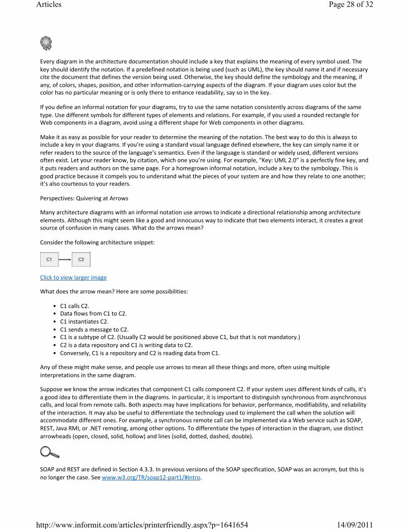
Every diagram in the architecture documentation should include a key that explains the meaning of every symbol used. The key should identify the notation. If a predefined notation is being used (such as UML), the key should name it and if necessary cite the document that defines the version being used. Otherwise, the key should define the symbology and the meaning, if any, of colors, shapes, position, and other informationcarrying aspects of the diagram. If your diagram uses color but the color has no particular meaning or is only there to enhance readability, say so in the key.
If you define an informal notation for your diagrams, try to use the same notation consistently across diagrams of the same type. Use different symbols for different types of elements and relations. For example, if you used a rounded rectangle for Web components in a diagram, avoid using a different shape for Web components in other diagrams.
Make it as easy as possible for your reader to determine the meaning of the notation. The best way to do this is always to include a key in your diagrams. If you’re using a standard visual language defined elsewhere, the key can simply name it or refer readers to the source of the language’s semantics. Even if the language is standard or widely used, different versions often exist. Let your reader know, by citation, which one you’re using. For example, “Key: UML 2.0” is a perfectly fine key, and it puts readers and authors on the same page. For a homegrown informal notation, include a key to the symbology. This is good practice because it compels you to understand what the pieces of your system are and how they relate to one another; it’s also courteous to your readers.
Perspectives: Quivering at Arrows
Many architecture diagrams with an informal notation use arrows to indicate a directional relationship among architecture elements. Although this might seem like a good and innocuous way to indicate that two elements interact, it creates a great source of confusion in many cases. What do the arrows mean?
Consider the following architecture snippet:
Click to view larger image
What does the arrow mean? Here are some possibilities:
• C1 calls C2.• Data flows from C1 to C2.• C1 instantiates C2.• C1 sends a message to C2.• C1 is a subtype of C2. (Usually C2 would be positioned above C1, but that is not mandatory.)• C2 is a data repository and C1 is writing data to C2.• Conversely, C1 is a repository and C2 is reading data from C1.
Any of these might make sense, and people use arrows to mean all these things and more, often using multiple interpretations in the same diagram.
Suppose we know the arrow indicates that component C1 calls component C2. If your system uses different kinds of calls, it’s a good idea to differentiate them in the diagrams. In particular, it is important to distinguish synchronous from asynchronous calls, and local from remote calls. Both aspects may have implications for behavior, performance, modifiability, and reliability of the interaction. It may also be useful to differentiate the technology used to implement the call when the solution will accommodate different ones. For example, a synchronous remote call can be implemented via a Web service such as SOAP, REST, Java RMI, or .NET remoting, among other options. To differentiate the types of interaction in the diagram, use distinct arrowheads (open, closed, solid, hollow) and lines (solid, dotted, dashed, double).
SOAP and REST are defined in Section 4.3.3. In previous versions of the SOAP specification, SOAP was an acronym, but this is no longer the case. See www.w3.org/TR/soap12part1/#intro.
Page 28 of 32Articles
14/09/2011http://www.informit.com/articles/printerfriendly.aspx?p=1641654
Suppose that we know that C1 calls C2. Sometimes we feel tempted to also show a data flow between the two. We could use the preceding figure and assume the arrow indicates data flow (instead of “calls”), but if C2 returns a value to C1, shouldn’t an arrow go both ways? Or should a single arrow have two arrowheads? These two options are not interchangeable. A doubleheaded arrow typically denotes a symmetric relationship between two elements, whereas two singleheaded arrows suggest two asymmetric relationships at work. In either case, the diagram will lose the information that C1 initiated the interaction. Suppose that C2 also invokes C1. Would we need to put two doubleheaded arrows between C1 and C2? When a component C1 calls a component C2, C1 may pass data as arguments to C2 and C2 may return data back to C1. Therefore, it’s often a better idea to use the arrow to indicate the call’s relation rather than data flow; otherwise the diagram may easily end up full of doubleheaded arrows that don’t tell much.
Although arrows are often used to indicate interactions, often one can avoid confusion by not using them where they are likely to be misinterpreted. For example, one can use lines without arrowheads. Sometimes physical placement, rather than lines, can convey the same information. For example, a layer A on top of a layer B indicates that modules in A can use modules in B. Nesting one element inside another often means “is part of.”
Finally, a good key is essential for understanding the meaning of arrows, even ones that represent “simple” interactions such as “calls.” A useful arrow, suitably explained in the key, will leave no doubt as to which is the calling end and which is the called end of a callreturn connector, and which way the data flows.
—D.G. and P.M.
Rule 4: Use a Standard Organization
Establish a standard, planned organization scheme, make your documents adhere to it, and ensure that readers know about it. A standard organization, also called a template, offers many benefits.
Section I.2, in the introduction to Part I, contains a standard organization for a style guide. Sections 10.1 and 10.2 contain a standard organization that we recommend for documenting views and information beyond views. Chapter 7 contains a standard organization for the documentation of a software interface.
• It helps the reader navigate the document and find specific information quickly. Thus, this benefit is also related to the writeforthereader rule.
• It also helps the document writer plan and organize the contents. The writer doesn’t have to start with a blank page when answering the question “What topics and in what order should I have in this document?” The template already provides an outline of the important topics to cover.
• It allows the writer to record information as soon as it’s known. For example, pieces of section 4 may be written before sections 1–3 are there.
• It reveals what work remains to be done by the number of sections labeled “TBD” (to be determined) or “To Do.”• It embodies completeness rules for the information; the sections of the document constitute the set of important
aspects that need to be conveyed. Hence, the standard organization can form the basis for a firstorder validation check of the document at review time.
Take any long explanations of figures that are in the main text and move these to the figures’ captions. Intext explanations would serve firsttime readers well, but putting explanations in captions will serve secondtime readers better: When they see a figure they’re looking for they won’t have to go search the text for its explanation.—Instructions to the editors of this book, explaining one way in which we tried to organize the book for ease of reference
Corollaries to this rule are these:
1. Organize documentation for ease of reference. Software documentation may be read from cover to cover at most once, probably never. But a document is likely to be referenced hundreds or thousands of times. Do what you can to make it easy to find information quickly. Adding a table of contents, an index, a glossary, and an acronym list are all good ways to help readers look up specific information.
Page 29 of 32Articles
14/09/2011http://www.informit.com/articles/printerfriendly.aspx?p=1641654
Don’t leave sections blank. Mark them as “not applicable” or “to be determined,” as appropriate. Better: “Not applicable because [reason]” and “To be determined by [date or milestone].”
2. Don’t leave any section blank; mark as “TBD” what you don’t yet know or “NA” what you know is not applicable. Many times, we can’t fill in a document completely because we don’t yet know the information, or because decisions have not been made, or because we didn’t yet have time to do it. In that case, mark the document accordingly (for example, “TBD” or “To Do”). Templates are by nature generic and hence comprehensive. If a given section of the template does not apply for the document you’re creating, mark it as “NA.” If the section is blank, the reader will wonder whether the information is coming later or whether it is indeed supposed to be blank. Thus this advice is related to the rule about avoiding ambiguity.
Rule 5: Record Rationale
Architecture is the result of making a set of important design decisions, and architecture documentation records the outcomes of those decisions. For the most important decisions, you should record why you made them the way you did. You should also record the important or most likely alternatives you rejected and state why. Later, when those decisions come under scrutiny or pressure to change, you will find yourself revisiting the same arguments and wondering why you didn’t take another path. Recording your rationale will save you enormous time in the long run, although it requires discipline to record your rationale in the heat of the moment.
“Well, it’s an idea, and even a bad idea is better than none,” said Master Li. “Error can point the way to truth, while emptyheadedness can only lead to more emptyheadedness or to a career in politics.”—Barry Hughart, Bridge of Birds (1984)
Of course, not every single design decision should have the rationale captured in the architecture documentation. If a design decision is key to achieve a quality requirement of the system, its rationale is probably worth capturing. If a design decision required a long meeting with stakeholders, that’s a good decision to capture. If you conducted technical experiments and studies or created prototypes to evaluate design alternatives, the conclusions of this effort should be captured as rationale for the chosen alternative. Keep in mind that one week, one month, or one year from now, you may not remember why you did things that way, and other people will not know either.
Section 6.5 discusses the documentation of rationale.
Rule 6: Keep Documentation Current but Not Too Current
Documentation that is incomplete or out of date does not reflect truth, does not obey its own rules for form and internal consistency, and is not used. Documentation that is kept current and accurate is used. Why? Because questions about the software can be most easily and most efficiently answered by referring to the appropriate document. Documentation that is somehow inadequate to answer the question needs to be fixed. Updating it and then referring the questioner to it will deliver a strong message that the documentation is the final, authoritative source for information.
Even with the best intentions, sometimes budget and schedule preclude conscientious updating of an architecture document as the system undergoes change. In that case, as happens all too often, the code becomes the final source of authority. Try to use the formula in Section P.2.4 to justify maintaining the document by making a case that doing so is worth the investment. If that fails, then at least mark the sections of the document that are out of date so that readers can still have confidence in the remainder.
Page 30 of 32Articles
14/09/2011http://www.informit.com/articles/printerfriendly.aspx?p=1641654
During the design process, on the other hand, decisions are made and reconsidered with great frequency. Revising documentation to reflect decisions that will not persist is an unnecessary expense.
Your development plan should specify particular points at which the documentation is brought up to date or the process for keeping the documentation current. For example, the end of each iteration or sprint, or each incremental release, could be associated with providing revised documentation. Every design decision should not be recorded and distributed the instant it is made; rather, the document should be subject to version control and have a release strategy, just as every other artifact does.
Rule 7: Review Documentation for Fitness of Purpose
Only the intended users of a document will be able to tell you whether it contains the right information presented in the right way. Enlist their aid. Before a document is released, have it reviewed by representatives of the community or communities for which it was written.
Chapter 11 covers reviewing architecture documents.
P.6 Summary Checklist
• The goal of documenting an architecture is to write it down so that others can successfully use it, maintain it, and build a system from it.
• Documentation exists to further architecture’s uses as a means of education, as a vehicle for communication among stakeholders, and as the basis for analysis.
• Documenting an architecture is a matter of documenting the relevant views and then adding documentation that applies to more than one view.
• Documentation should pay for itself by making development activities less costly.• Module styles help architects think about their software as a set of implementation units. C&C views help architects
think about their software as a set of elements that have runtime behavior and interactions. Allocation views help architects think about how their software relates to the nonsoftware structures in its environment.
• An architecture style is a specialization of elements and relations, together with a set of constraints on how they can be used. A style defines a family of architectures that satisfy the constraints.
• Some styles are applicable in every software system. Other styles occur only in systems in which they were explicitly chosen and designed in by the architect.
• Follow the seven rules for sound documentation. 1. Write documentation from the point of view of the reader, not the writer.2. Avoid unnecessary repetition.3. Avoid ambiguity. Always explain your notation.4. Use a standard organization.5. Record rationale.6. Keep documentation current but not too current.7. Review documentation for fitness of purpose.
P.7 Discussion Questions
1. Think of a technical document that you remember as being exceptionally useful. What made it so?2. Think of a technical document that you remember as being dreadful. What made it so?3. List several architectural aspects of a system you’re familiar with, and state why they are. List several aspects that are
not architectural, and state why they are not. List several aspects that are “on the cusp,” and make a compelling argument for putting each into “architectural” or “nonarchitectural” categories.
4. If you visit Seoul, Korea, you might see the following sign presiding over one of the busy downtown thoroughfares:
Click to view larger image
Page 31 of 32Articles
14/09/2011http://www.informit.com/articles/printerfriendly.aspx?p=1641654

What does it mean? Is the information this sign conveys structural, behavioral, or both? What are the elements in this system? Are they more like modules or like components? What qualities about the notation make this sign understandable or not understandable? Does the sign convey a dynamic architecture, or dynamic behavior within a static architecture? Who are the stakeholders of this sign? What quality attributes is it attempting to achieve? How would you validate it, to assure yourself that it was satisfying its requirements?
5. How much of a project’s budget would you devote to software architecture documentation? Why? How would you measure the cost and the benefit?
P.8 For Further Reading
The full treatment of software architecture—how to build one, how to evaluate one to make sure it’s a good one, how to recover one from a jumble of legacy code, and how to drive a development effort once you have one—is beyond the scope of this book. However, general books on software architecture are plentiful. Several authors provide good coverage: Bass, Clements, and Kazman (2003); Hofmeister, Nord, and Soni (2000); Shaw and Garlan (1996); Bosch (2000); and Gorton (2006). Also, Jeff Garland and Richard Anthony’s Large-Scale Software Architecture: A Practical Guide Using UML is a good resource (Garland and Anthony 2003).
The Software Engineering Institute’s software architecture Web page—at www.sei.cmu.edu/architecture—provides a wide variety of software architecture resources and links, including a broad collection of definitions of the term (SEI 2010).
One of the goals of documentation is to provide sufficient information so that an architecture can be analyzed for fitness of purpose. For more about analysis and evaluation of software architectures, see the book by Clements, Kazman, and Klein (2002).
The seven rules of sound documentation are adapted from a paper by Parnas and Clements (1986), which also espouses a philosophy directly relevant to this book. That paper holds that although system design is almost always subject to errors, false starts, and resourceconstrained compromises, systems should be documented as though they were the product of an idealized, stepbystep, smoothly executed design process. That is the documentation that will be the most helpful in the long run. This book is consistent with that philosophy, in that it lays out what the end state of your documentation should be.
If you want a deeper appreciation of the field of architecture and its roots, then diving into some of the early papers will be worth your time:
David Parnas (1974) first made the observation that software can be described by many structures, not just one. This insight led directly to the concept of views that we use today. Architecture views in general, and “4+1 views” in particular, are a fundamental aspect of the Rational (now IBM Rational) Unified Process for objectoriented software (Kruchten 1995).
An early paper on software architecture that tied us to building architecture and our “architecture styles” to the architecture styles of buildings is by Perry and Wolf (1992).
A tour de force in style comparison is found in the paper by Shaw (1995), in which the author examines 11 different previously published solutions to the automobile cruisecontrol problem and compares each solution through the lens of architecture style. Chapter 3 of the book by Shaw and Garlan (1996) continues the theme. A number of example problems are presented. For each one, several architecture solutions are presented, each based on the choice of a different style. These sidebyside comparisons not only reveal qualities of the styles themselves, but also richly illustrate the overall concept.
For encyclopedic catalogs of architecture patterns, see the Pattern-Oriented Software Architecture series of books by the following authors: Buschmann et al. (1996); Schmidt et al. (2000); Kircher and Jain (2004); and Buschmann, Henney, and Schmidt (2007a and 2007b). Also see Martin Fowler’s book Patterns of Enterprise Application Architecture (2002).
Smith and Williams (2002) include three chapters of principles and guidance for architecting systems in which performance is an overriding concern.
© 2011 Pearson Education, Inc. All rights reserved.800 East 96th Street Indianapolis, Indiana 46240
Page 32 of 32Articles
14/09/2011http://www.informit.com/articles/printerfriendly.aspx?p=1641654
Software Design Document (SDD) Template
Software design is a process by which the software requirements are translated into a representation of software components, interfaces, and data necessary for the implementation phase. The SDD shows how the software system will be structured to satisfy the requirements. It is the primary reference for code development and, therefore, it must contain all the information required by a programmer to write code. The SDD is performed in two stages. The first is a preliminary design in which the overall system architecture and data architecture is defined. In the second stage, i.e. the detailed design stage, more detailed data structures are defined and algorithms are developed for the defined architecture.
This template is an annotated outline for a software design document adapted from the IEEE Recommended Practice for Software Design Descriptions. The IEEE Recommended Practice for Software Design Descriptions have been reduced in order to simplify this assignment while still retaining the main components and providing a general idea of a project definition report. For your own information, please refer to IEEE Std 10161998 1 for the full IEEE Recommended Practice for Software Design Descriptions.
1 http://www.cs.concordia.ca/~ormandj/comp354/2003/Project/ieeeSDD.pdf

(Team Name) (Project Title) Software Design Document
Name (s): Lab Section: Workstation:
Date: (mm/dd/yyyy)

Software Design Document
1
TABLE OF CONTENTS
1. INTRODUCTION 2 1.1 Purpose 2 1.2 Scope 2
1.3 Overview 2 1.4 Reference Material 2
1.5 Definitions and Acronyms 2
2. SYSTEMOVERVIEW 2
3. SYSTEMARCHITECTURE 2 3.1 Architectural Design 2
3.2 Decomposition Description 3 3.3 Design Rationale 3
4. DATA DESIGN 3 4.1 Data Description 3
4.2 Data Dictionary 3
5. COMPONENT DESIGN 3
6. HUMAN INTERFACE DESIGN 4 6.1 Overview of User Interface 4
6.2 Screen Images 4 6.3 Screen Objects and Actions 4
7. REQUIREMENTSMATRIX 4
8. APPENDICES 4
Software Design Document
2
1. INTRODUCTION
1.1 Purpose Identify the purpose of this SDD and its intended audience. (e.g. “This software design document describes the architecture and system design of XX. ….”).
1.2 Scope Provide a description and scope of the software and explain the goals, objectives and benefits of your project. This will provide the basis for the brief description of your product.
1.3 Overview Provide an overview of this document and its organization.
1.4 Reference Material This section is optional. List any documents, if any, which were used as sources of information for the test plan.
1.5 Definitions and Acronyms This section is optional. Provide definitions of all terms, acronyms, and abbreviations that might exist to properly interpret the SDD. These definitions should be items used in the SDD that are most likely not known to the audience.
2. SYSTEM OVERVIEW
Give a general description of the functionality, context and design of your project. Provide any background information if necessary.
3. SYSTEM ARCHITECTURE
3.1 Architectural Design Develop a modular program structure and explain the relationships between the modules to achieve the complete functionality of the system. This is a high level overview of how
Software Design Document
3
responsibilities of the system were partitioned and then assigned to subsystems. Identify each high level subsystem and the roles or responsibilities assigned to it. Describe how these subsystems collaborate with each other in order to achieve the desired functionality. Don’t go into too much detail about the individual subsystems. The main purpose is to gain a general understanding of how and why the system was decomposed, and how the individual parts work together. Provide a diagram showing the major subsystems and data repositories and their interconnections. Describe the diagram if required.
3.2 Decomposition Description
Provide a decomposition of the subsystems in the architectural design. Supplement with text as needed. You may choose to give a functional description or an objectoriented description. For a functional description, put toplevel data flow diagram (DFD) and structural decomposition diagrams. For an OO description, put subsystem model, object diagrams, generalization hierarchy diagram(s) (if any), aggregation hierarchy diagram(s) (if any), interface specifications, and sequence diagrams here.
3.3 Design Rationale Discuss the rationale for selecting the architecture described in 3.1 including critical issues and trade/offs that were considered. You may discuss other architectures that were considered, provided that you explain why you didn’t choose them.
4. DATA DESIGN
4.1 Data Description Explain how the information domain of your system is transformed into data structures. Describe how the major data or system entities are stored, processed and organized. List any databases or data storage items.
4.2 Data Dictionary Alphabetically list the system entities or major data along with their types and descriptions. If you provided a functional description in Section 3.2, list all the functions and function parameters. If you provided an OO description, list the objects and its attributes, methods and method parameters.
5. COMPONENT DESIGN
In this section, we take a closer look at what each component does in a more systematic way. If
Software Design Document
4
you gave a functional description in section 3.2, provide a summary of your algorithm for each function listed in 3.2 in procedural description language (PDL) or pseudocode. If you gave an OO description, summarize each object member function for all the objects listed in 3.2 in PDL or pseudocode. Describe any local data when necessary.
6. HUMAN INTERFACE DESIGN
6.1 Overview of User Interface
Describe the functionality of the system from the user’s perspective. Explain how the user will be able to use your system to complete all the expected features and the feedback information that will be displayed for the user.
6.2 Screen Images Display screenshots showing the interface from the user’s perspective. These can be hand drawn or you can use an automated drawing tool. Just make them as accurate as possible. (Graph paper works well.)
6.3 Screen Objects and Actions
A discussion of screen objects and actions associated with those objects.
7. REQUIREMENTS MATRIX
Provide a crossreference that traces components and data structures to the requirements in your SRS document.
Use a tabular format to show which system components satisfy each of the functional requirements from the SRS. Refer to the functional requirements by the numbers/codes that you gave them in the SRS.
8. APPENDICES
This section is optional.

Software Design Document
5
Appendices may be included, either directly or by reference, to provide supporting details that could aid in the understanding of the Software Design Document.

IEEE P1016/D5.0; 12 December 2005
IEEE Draft Standard for Software Design Descriptions
Sponsor
Software & Systems Engineering Standards Committee of the
IEEE Computer Society
Abstract: The required information content and organization for Software Design Descriptions (SDDs) are described. An SDD is a representation of a software design to be used for communicating design information to its stakeholders. The requirements for the design languages (notations and other representational schemes) to be used for conformant SDDs are specified. This standard is applicable to automated databases and design description languages but can be used for paper documents and other means of descriptions. Keywords: design state, design subject, design view, design viewpoint, software design, software design description, diagram.
Copyright © 2005 by IEEE P1016 Working Group
All rights reserved. This document is an unapproved draft of a proposed IEEE Standard. As such, this document is subject to change. USE AT YOUR OWN RISK! Because this is an unapproved draft, this document must not be utilized for any conformance/compliance purposes. Permission is hereby granted for IEEE Standards Committee participants to reproduce this document for purposes of IEEE standardization activities only. Prior to submitting this document to another standards development organization for standardization activities, permission must first be obtained from the Manager, Standards Licensing and Contracts, IEEE Standards Activities Department. Other entities seeking permission to reproduce this document, in whole or in part, must obtain permission from the Manager, Standards Licensing and Contracts, IEEE Standards Activities Department.
IEEE Standards Activities Department Standards Licensing and Contracts 445 Hoes Lane, P.O. Box 1331 Piscataway, NJ 08855-1331, USA

12 December 2005 IEEE P1016/D5.0
Copyright © 2005 IEEE P1016 Working Group. All rights reserved. This is an unapproved IEEE Standards Draft, subject to change.
ii
Introduction
(This introduction is not part of IEEE P1016, IEEE Standard for Software Design Descriptions.)
This standard specifies requirements on the information content and organization for Software Design Descriptions (SDDs). An SDD is a representation of a software design that is to be used for recording design information addressing various design concerns and communicating that information to the design’s stakeholders.
SDDs play a pivotal role in the development and maintenance of software systems. During its lifetime, an SDD is used by acquirers, project managers, quality assurance staff, configuration managers, software designers, programmers, testers, and maintainers. Each of these stakeholders has unique needs, both in terms of required design information and optimal organization of that information. Hence, a design description will contain the design information needed by those stakeholders.
The standard also specifies requirements on the design languages to be used when producing SDDs conforming to these requirements on content and organization.
The standard specifies that an SDD be organized into a number of design views. Each view addresses a specific set of design concerns of the stakeholders. Each design view is prescribed by a design viewpoint. A viewpoint identifies the design concerns to be focused upon within its view and selects the design languages used to record that design view. The standard establishes a common set of viewpoints for design views, as a starting point for the preparation of a SDD, and a generic capability for defining new design viewpoints thereby expanding the expressiveness of an SDD for its stakeholders.
This standard is intended for use in design situations in which an explicit software design description is to be prepared. These situations include traditional software design and construction activities leading to an implementation as well as “reverse engineering” situations where a design description is to be recovered from an existing implementation.
This standard can be applied to commercial, scientific, military and other types of software. Applicability is not restricted by size, complexity, or criticality of the software. This standard considers both the software and its system context, including the developmental and operational environment. It can be used where software comprises the system or where software is part of a larger system characterized by hardware, software and human components and their interfaces.
This standard is applicable whether the SDD is captured using paper documents, automated databases, software development tools or other media. This standard does not explicitly support, nor is it limited to, use with any particular software design methodology or particular design languages, although it establishes minimum requirements on the selection of those design languages.
This standard is consistent for use with IEEE/EIA Std 12207.0–1996, Software Life Cycle; it may also be applied in other life cycle contexts.
This standard consists of six clauses.
Clause 1 defines the scope and purpose of the standard.
Clause 2 references documents containing material required to understand and apply the standard.
Clause 3 provides definitions of terms used within the context of the standard.
Clause 4 provides a framework for understanding software design descriptions in the context of their preparation and use.
Clause 5 describes the required content and organization of an SDD.
12 December 2005 IEEE P1016/D5.0
Copyright © 2005 IEEE P1016 Working Group. All rights reserved. This is an unapproved IEEE Standards Draft, subject to change.
iii
Clause 6 defines several design viewpoints.
Annex A provides a bibliography.
Annex B defines how a design language to be used in an SDD may be described in a uniform manner.
Annex C contains templates for organizing an SDD conforming to the requirements of this standard.
This standard follows the IEEE Standards Style Manual. In particular, the word shall identifies requirements that must be satisfied in order to claim conformance with this standard. The verb should identifies recommendations and the verb may is used to denote that particular courses of action are permissible.
This standard is modeled after IEEE Std 1471, extending it primarily to support detailed design and construction for software. The demarcation between architecture, high-level and detailed design is arbitrary for small to medium sized systems. While IEEE 1471 recommends the use of certain viewpoints, P1016 requires the use of specific viewpoints.
At the time this standard was completed, the working group had the following membership: Vladan V. Jovanovic, Chair (acting) Basil A. Sherlund, Chair (emeritus) Rich Hilliard, Secretary and Technical Editor
Nenad Anicic
Edward Byrne
Bob Cook
Ed Corlett
Philippe Kruchten
Kathy Land
Joaquin Miller
James Moore
Stevan Mrdalj
Ira Sachs
Judith Speights
The following members of the balloting committee voted on this standard. Balloters may have voted for approval, disapproval, or abstention. (To be provided by IEEE editor at time of publication.)
12 December 2005 IEEE P1016/D5.0
Copyright © 2005 IEEE P1016 Working Group. All rights reserved. This is an unapproved IEEE Standards Draft, subject to change.
iv
TABLE OF CONTENTS
INTRODUCTION.................................................................................................. II
1. OVERVIEW ................................................................................................... 7
1.1 Scope ............................................................................................................................................................ 7
1.2 Purpose........................................................................................................................................................ 7
1.3 Intended Audience..................................................................................................................................... 7
1.4 Conformance .............................................................................................................................................. 8
2. REFERENCES .............................................................................................. 8
3. DEFINITIONS................................................................................................ 8
4. CONCEPTUAL FRAMEWORK FOR SOFTWARE DESIGN DESCRIPTIONS 9
4.1 Software Design in Context...................................................................................................................... 9
4.2 Software Design Descriptions within the Life Cycle.......................................................................... 12 4.2.1 Influences on SDD Preparation ......................................................................................................... 12 4.2.2 SDD Influences on Software Life Cycle Products........................................................................... 13 4.2.3 Design Verification and Design Role in Validation ........................................................................ 13
5. DESIGN DESCRIPTION INFORMATION CONTENT ................................. 13
5.1 Introduction.............................................................................................................................................. 13
5.2 SDD Identification ................................................................................................................................... 13
5.3 Design Stakeholders and Concerns ...................................................................................................... 14
5.4 Design views.............................................................................................................................................. 14
5.5 Design viewpoints .................................................................................................................................... 15
5.6 Design elements........................................................................................................................................ 15 5.6.1 Design entities .................................................................................................................................... 15 5.6.2 Design attributes................................................................................................................................. 16 5.6.3 Design relationships ........................................................................................................................... 17 5.6.4 Design constraints .............................................................................................................................. 17
5.7 Design overlays ........................................................................................................................................ 17
12 December 2005 IEEE P1016/D5.0
Copyright © 2005 IEEE P1016 Working Group. All rights reserved. This is an unapproved IEEE Standards Draft, subject to change.
v
5.8 Design rationale ....................................................................................................................................... 17
5.9 Design languages...................................................................................................................................... 18
6. DESIGN VIEWPOINTS ............................................................................... 18
6.1 Introduction.............................................................................................................................................. 18
6.2 Context Viewpoint ................................................................................................................................... 20 6.2.1 Design Concerns ................................................................................................................................ 20 6.2.2 View Elements ................................................................................................................................... 21 6.2.3 Example languages............................................................................................................................. 22
6.3 Composition Viewpoint .......................................................................................................................... 22 6.3.1 Design concerns ................................................................................................................................. 22 6.3.2 View elements .................................................................................................................................... 22 6.3.3 Example languages............................................................................................................................. 23
6.4 Logical Viewpoint .................................................................................................................................... 23 6.4.1 Design Concerns .................................................................................................................................... 23 6.4.2 View elements ........................................................................................................................................ 23 6.4.3 Example languages ................................................................................................................................ 23
6.5 Dependency Viewpoint ........................................................................................................................... 23 6.5.1 Design concerns ................................................................................................................................. 23 6.5.2 View elements .................................................................................................................................... 24 6.5.3 Example Languages ........................................................................................................................... 24
6.6 Information Viewpoint ........................................................................................................................... 24 6.6.1 Design concerns ................................................................................................................................. 24 6.6.2 View elements .................................................................................................................................... 24 6.6.3 Example Languages ........................................................................................................................... 25
6.7 Patterns Use Viewpoint .......................................................................................................................... 25 6.7.1 Design concerns ................................................................................................................................. 25 6.7.2 View elements .................................................................................................................................... 25 6.7.3 Example languages............................................................................................................................. 25
6.8 Interface Viewpoint ................................................................................................................................. 25 6.8.1 Design concerns ................................................................................................................................. 25 6.8.2 View elements .................................................................................................................................... 26 6.8.3 Example Languages ........................................................................................................................... 26
6.9 Structure Viewpoint ................................................................................................................................ 26 6.9.1 Design concerns ................................................................................................................................. 26 6.9.2 View elements .................................................................................................................................... 26 6.9.3 Example languages............................................................................................................................. 27
6.10 Interaction Viewpoint ........................................................................................................................... 27 6.10.1 Design concerns ............................................................................................................................... 27 6.10.2 View elements .................................................................................................................................. 27 6.10.3 Examples........................................................................................................................................... 27
12 December 2005 IEEE P1016/D5.0
Copyright © 2005 IEEE P1016 Working Group. All rights reserved. This is an unapproved IEEE Standards Draft, subject to change.
vi
6.11 State Dynamics Viewpoint ................................................................................................................... 27 6.11.1 Design concerns ............................................................................................................................... 27 6.11.2 View elements .................................................................................................................................. 27 6.11.3 Example languages .......................................................................................................................... 27
6.12 Algorithm Viewpoint ............................................................................................................................ 27 6.12.1 Design concerns ............................................................................................................................... 28 6.12.2 View elements .................................................................................................................................. 28 6.12.3 Examples........................................................................................................................................... 28
6.13 Resource Viewpoint .............................................................................................................................. 28 6.13.1 Design concerns ............................................................................................................................... 28 6.13.2 View elements .................................................................................................................................. 28 6.13.3 Examples........................................................................................................................................... 29
ANNEX A (INFORMATIVE) BIBLIOGRAPHY................................................... 30
ANNEX B (INFORMATIVE) CONFORMING DESIGN LANGUAGE DESCRIPTION................................................................................................... 32
B.1 Information on Conforming Design Languages (normative?) ........................................................ 32
B.2 Example: StateCharts ............................................................................................................................ 33
B.3 Example: IDEF0 ..................................................................................................................................... 33
B.4 Example: IDEF1 ..................................................................................................................................... 34
ANNEX C (INFORMATIVE) TEMPLATES FOR AN SDD ................................. 36
12 December 2005 IEEE P1016/D5.0
Copyright © 2005 IEEE P1016 Working Group. All rights reserved. This is an unapproved IEEE Standards Draft, subject to change.
7
IEEE Draft Standard for Software Design Descriptions
1. Overview
1.1 Scope
This is a standard for software design descriptions (SDD). An SDD is a representation of a software design to be used for recording design information and communicating that design information to key design stakeholders.
This standard is intended for use in design situations in which an explicit software design description is to be prepared. These situations include traditional software construction activities, when design leads to code, and “reverse engineering” situations where a design description is to be recovered from an existing implementation.
The standard can be applied to commercial, scientific, or military software that runs on digital computers. Applicability is not restricted by the size, complexity, or criticality of the software. This standard can be applied to the description of high-level and detailed designs.
This standard is not limited to use with specific methodologies for design, configuration management, or quality assurance. This standard does not require the use of any particular design languages, but establishes requirements on the selection of design languages for use in an SDD. The standard can be applied to the preparation of SDDs captured as paper documents, automated databases, software development tools or other media.
NOTE—The requirements in P1016 are intended to be consistent with the use of other IEEE standards (specifically, IEEE 830, IEEE 1012, IEEE 1471 and IEEE/EIA 12207).
1.2 Purpose
This standard specifies requirements on the information content and metadata organization of SDDs. This standard specifies requirements for the selection of design languages to be used for software design description, and requirements for documenting design viewpoints to be used in organizing a software design description.
1.3 Intended Audience
This standard is intended for technical and managerial stakeholders who prepare and use SDDs. It will guide a designer in the selection, organization, and presentation of design information. For an organization developing its own design description practices, the use of this standard will help to ensure that design descriptions are complete, concise, consistent, interchangeable, appropriate for recording design experiences and lessons learned, well organized and easy to communicate.
12 December 2005 IEEE P1016/D5.0
Copyright © 2005 IEEE P1016 Working Group. All rights reserved. This is an unapproved IEEE Standards Draft, subject to change.
8
1.4 Conformance
A Software Design Description conforms to this standard if it satisfies all of the requirements of this standard. Requirements are denoted by the verb shall.
2. References
None
3. Definitions
For the purposes of this standard, the following terms and definitions apply. The IEEE Standard Dictionary of Electrical and Electronics Terms [IEEE Std 100], and Industry Implementation of International Standard ISO/IEC 12207:1995 Software life cycle processes [IEEE/EIA Std 12207.0–1996] should be referenced for terms not defined in this clause.
design concern: an area of interest with respect to a software design.
design constraint: an element of a design view which names and specifies a rule or restriction on a design entity, design attribute or design relationship. See: design entity, design relationship, design attribute
NOTE—May need to reconcile with an earlier IEEE definition: design constraint: Any requirement that affects or constrains the design of a software system or software system component (for example, physical requirements, performance requirements, software development standards, software quality assurance standards). [ANSI/IEEE Std 610.12-1990]
design element: an item occurring in a design view which may be any of the following: design entity, design relationship, design attribute, or design constraint.
design attribute: an element of a design view which names a characteristic or property of a design entity, design relationship or design constraint. See: design entity, design relationship, design constraint
design entity: an element of a design view which is structurally, functionally or otherwise distinct from other elements, or plays a different role relative to other design entities. See: design view
design overlay: a representation of additional, detailed or derived design information organized with reference to a previously-defined design view.
design rationale: information capturing the reasoning of the designer which led to the system as designed, including design options, tradeoffs considered, decisions made, and the justifications of those decisions.
design relationship: an element of a design view which names a connection or correspondence between design entities. See: design entity
design stakeholder: an individual, organization or group (or classes thereof playing the same role) having an interest in, or design concerns relative to, the design of some software item. See: design concern
design subject: any software item or system which is to be constructed or which already exists and is to be analyzed, for which a software design description will be prepared. Alternate terms to consider: software under design or system under design.
designer: the stakeholder responsible for devising and documenting the software design.
12 December 2005 IEEE P1016/D5.0
Copyright © 2005 IEEE P1016 Working Group. All rights reserved. This is an unapproved IEEE Standards Draft, subject to change.
9
design view: a representation comprised of one or more design elements to address a set of design concerns from a specified design viewpoint. See: design concern, design element, design viewpoint
design viewpoint: a specification of the elements and conventions available for constructing and using a design view. See: design view
diagram (type): a logically coherent fragment of a design view, using selected graphical icons and conventions for visual representation from an associated design language, to be used for representing selected design elements of interest for a system under design from a single viewpoint See: design subject
4. Conceptual Framework for Software Design Descriptions
This clause establishes a conceptual framework for Software Design Descriptions. The conceptual framework includes basic terms and concepts of software design description, the context in which SDDs are prepared and used, the stakeholders who use them, and how they are used.
4.1 Software Design in Context
A design is a framework which demonstrates a means to fulfill the requirements for some software item and to guide the implementation of that software item. A design subject is any software item to be constructed or which already exists and is to be analyzed, without loss of generality we will also refer to a design subject as the system under design or software under design. This standard does not establish what a design subject may be. Examples of design subjects include systems, subsystems, applications, components, libraries, application frameworks, application program interfaces (APIs) and design pattern catalogs.
A software design description (SDD) is a representation of some design subject of interest. An SDD is prepared to represent exactly one design subject. An SDD can be produced to capture one or more levels or layers of concern with respect to its design subject. These levels or layers are usually defined by the design methods in use or the life cycle context; they have names such as architectural design, logical design, or physical design. An SDD can be prepared and used in a variety of design situations. Typically, an SDD is prepared to support the development of a software item to solve a problem, where this problem has been expressed in terms of a set of requirements. The contents of the SDD can then be traced to these requirements. In other cases, an SDD can be prepared to understand an existing system lacking any design documentation. Typically, there is a system under development or under review for which an SDD is to be described such that information of interest is to be captured, organized, presented and disseminated to all interested parties. This information of interest can be used for planning, analysis, implementation and evolution of the software system, by identifying and addressing essential design concerns. A design concern is any area of interest in the design, pertaining to its development, implementation, or operation. Design concerns are expressed by design stakeholders—those parties which may be individuals, groups and organizations with an interest in the design of the system. Frequently design concerns arise from specific requirements on the software, others arise from contextual constraints. Typical design concerns include functionality, reliability, performance, and maintainability. Typical design stakeholders include users, developers, software designers, system integrators, maintainers, acquirers, and project managers.
NOTE—From a system-theoretic standpoint, an SDD is the information content of the design state space with convenient inputs (typically design diagrams and specifications produced by designers) and outputs (results of transformations typically produced by software tools). System state in case of design information typically contains alternative designs and design rationale information in addition to the minimal information of the current version of design. An interesting property of a design description as a system is that its configuration is subject to dynamic evolution and the respective state space (based on its design elements) is not given in advance but created iteratively in a manner of system analysis by synthesis. The final design (synthesis) is obtained via successive analysis of intermediate designs. Therefore, a design description can be considered an open, goal-directed system whose end state is a detailed model of the system under design.
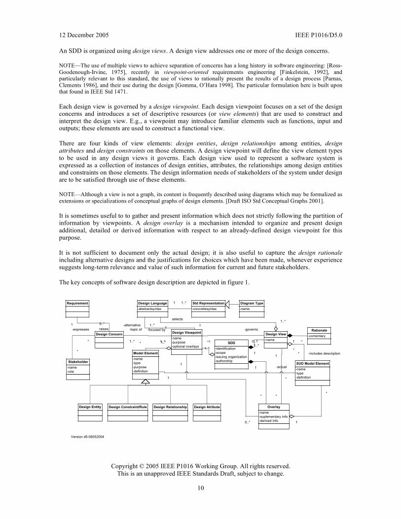
12 December 2005 IEEE P1016/D5.0
Copyright © 2005 IEEE P1016 Working Group. All rights reserved. This is an unapproved IEEE Standards Draft, subject to change.
10
An SDD is organized using design views. A design view addresses one or more of the design concerns.
NOTE—The use of multiple views to achieve separation of concerns has a long history in software engineering: [Ross-Goodenough-Irvine, 1975], recently in viewpoint-oriented requirements engineering [Finkelstein, 1992], and particularly relevant to this standard, the use of views to rationally present the results of a design process [Parnas, Clements 1986], and their use during the design [Gomma, O’Hara 1998]. The particular formulation here is built upon that found in IEEE Std 1471.
Each design view is governed by a design viewpoint. Each design viewpoint focuses on a set of the design concerns and introduces a set of descriptive resources (or view elements) that are used to construct and interpret the design view. E.g., a viewpoint may introduce familiar elements such as functions, input and outputs; these elements are used to construct a functional view.
There are four kinds of view elements: design entities, design relationships among entities, design attributes and design constraints on those elements. A design viewpoint will define the view element types to be used in any design views it governs. Each design view used to represent a software system is expressed as a collection of instances of design entities, attributes, the relationships among design entities and constraints on those elements. The design information needs of stakeholders of the system under design are to be satisfied through use of these elements.
NOTE—Although a view is not a graph, its content is frequently described using diagrams which may be formalized as extensions or specializations of conceptual graphs of design elements. [Draft ISO Std Conceptual Graphs 2001].
It is sometimes useful to to gather and present information which does not strictly following the partition of information by viewpoints. A design overlay is a mechanism intended to organize and present design additional, detailed or derived information with respect to an already-defined design viewpoint for this purpose.
It is not sufficient to document only the actual design; it is also useful to capture the design rationale including alternative designs and the justifications for choices which have been made, whenever experience suggests long-term relevance and value of such information for current and future stakeholders.
The key concepts of software design description are depicted in figure 1.
Requirement
Design Concern
1 0..*
1
1..*
Design Relationship
raises
1..*
*
1..*
1
selects
-name
-role
Stakeholder
*
-expresses
* 1
-governs
0..1
-topic of
1..*
-focused by
1..*
Version d5-08052004
*-includes description*
-comentary
Rationale
1 *
-name
-type
-purpose
-definition
Model Element
-name
-type
-definition
SUD Model Element
1
-actual
*
1..**
Design Constraint/Rule
-concretesyntax
Std Representation1..*1
-name
Diagram Type
-abstractsyntax
Design Language
1-alternative 1..*
1
*
1
*
1
*
Design Atribute
1
0..*
Design Entity
-name
-purpose
-optional overlays
Design Viewpoint
-identification
-scope
-issuing organization
-authorship
SDD-name
Design View
-name
-suplementary info
-derived info
Overlay
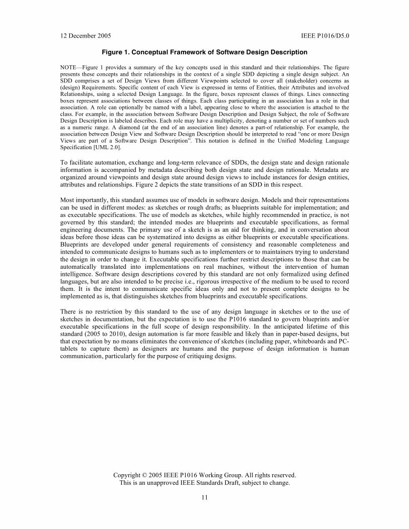
12 December 2005 IEEE P1016/D5.0
Copyright © 2005 IEEE P1016 Working Group. All rights reserved. This is an unapproved IEEE Standards Draft, subject to change.
11
Figure 1. Conceptual Framework of Software Design Description
NOTE—Figure 1 provides a summary of the key concepts used in this standard and their relationships. The figure presents these concepts and their relationships in the context of a single SDD depicting a single design subject. An SDD comprises a set of Design Views from different Viewpoints selected to cover all (stakeholder) concerns as (design) Requirements. Specific content of each View is expressed in terms of Entities, their Attributes and involved Relationships, using a selected Design Language. In the figure, boxes represent classes of things. Lines connecting boxes represent associations between classes of things. Each class participating in an association has a role in that association. A role can optionally be named with a label, appearing close to where the association is attached to the class. For example, in the association between Software Design Description and Design Subject, the role of Software Design Description is labeled describes. Each role may have a multiplicity, denoting a number or set of numbers such as a numeric range. A diamond (at the end of an association line) denotes a part-of relationship. For example, the association between Design View and Software Design Description should be interpreted to read “one or more Design Views are part of a Software Design Description”. This notation is defined in the Unified Modeling Language Specification [UML 2.0].
To facilitate automation, exchange and long-term relevance of SDDs, the design state and design rationale information is accompanied by metadata describing both design state and design rationale. Metadata are organized around viewpoints and design state around design views to include instances for design entities, attributes and relationships. Figure 2 depicts the state transitions of an SDD in this respect.
Most importantly, this standard assumes use of models in software design. Models and their representations can be used in different modes: as sketches or rough drafts; as blueprints suitable for implementation; and as executable specifications. The use of models as sketches, while highly recommended in practice, is not governed by this standard; the intended modes are blueprints and executable specifications, as formal engineering documents. The primary use of a sketch is as an aid for thinking, and in conversation about ideas before those ideas can be systematized into designs as either blueprints or executable specifications. Blueprints are developed under general requirements of consistency and reasonable completeness and intended to communicate designs to humans such as to implementers or to maintainers trying to understand the design in order to change it. Executable specifications further restrict descriptions to those that can be automatically translated into implementations on real machines, without the intervention of human intelligence. Software design descriptions covered by this standard are not only formalized using defined languages, but are also intended to be precise i.e., rigorous irrespective of the medium to be used to record them. It is the intent to communicate specific ideas only and not to present complete designs to be implemented as is, that distinguishes sketches from blueprints and executable specifications.
There is no restriction by this standard to the use of any design language in sketches or to the use of sketches in documentation, but the expectation is to use the P1016 standard to govern blueprints and/or executable specifications in the full scope of design responsibility. In the anticipated lifetime of this standard (2005 to 2010), design automation is far more feasible and likely than in paper-based designs, but that expectation by no means eliminates the convenience of sketches (including paper, whiteboards and PC-tablets to capture them) as designers are humans and the purpose of design information is human communication, particularly for the purpose of critiquing designs.
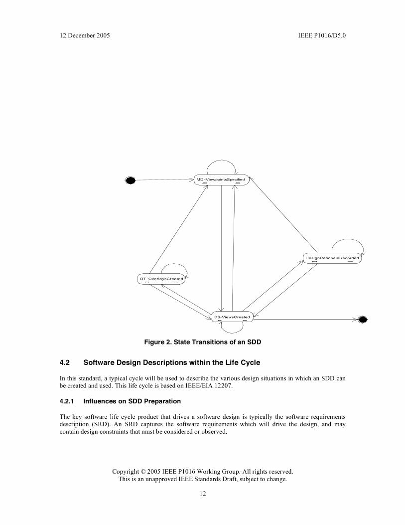
12 December 2005 IEEE P1016/D5.0
Copyright © 2005 IEEE P1016 Working Group. All rights reserved. This is an unapproved IEEE Standards Draft, subject to change.
12
MD -ViewpointsSpecified
DS-ViewsCreated
OT -OverlaysCreated
DesignRationaleRecorded
Figure 2. State Transitions of an SDD
4.2 Software Design Descriptions within the Life Cycle
In this standard, a typical cycle will be used to describe the various design situations in which an SDD can be created and used. This life cycle is based on IEEE/EIA 12207.
4.2.1 Influences on SDD Preparation
The key software life cycle product that drives a software design is typically the software requirements description (SRD). An SRD captures the software requirements which will drive the design, and may contain design constraints that must be considered or observed.
12 December 2005 IEEE P1016/D5.0
Copyright © 2005 IEEE P1016 Working Group. All rights reserved. This is an unapproved IEEE Standards Draft, subject to change.
13
4.2.2 SDD Influences on Software Life Cycle Products
The SDD influences the content of several major software life cycle products. Developers of these products will be recognized among the SDD’s intended audience. − Software Requirements Description. Design decisions, or design constraints discovered during the
preparation of the SDD, may lead to requirements changes. Often traceability between requirements and design is maintained to manage these changes.
− Test Documentation. Test planning can be influenced by the SDD, but any white-box testing activities at the level of unit, integration, and system testing, are directly influenced by the SDD. Developers of any test specifications and test cases that relate to this type of testing should cover the design functionality, relationships, objects, and data descriptions contained in the SDD.
4.2.3 Design Verification and Design Role in Validation
Verification is a process for determining whether the software products of an activity fulfill the requirements or conditions imposed on them in the previous activities. [IEEE/EIA 12207.0] An SDD can be subject to design verification to ascertain whether the design: is consistent with stated requirements; implements intended design decisions (such as those pertaining to interfaces, inputs, outputs, algorithms, resource allocation, and error handling); achieves intended qualities (such as safety, security, maintainability); and conforms to an imposed architecture. Verification therefore raises a set of design concerns which can be dealt with in the SDD and subjected to inspection or analysis.
Validation is a process for determining whether the requirements and the final, as-built system or software product fulfills its specific intended use. [IEEE/EIA 12207.0] The SDD can play a role in this process mainly by providing: an overview necessary for understanding the implementation; the rationale justifying design decisions made; and traceability back to the requirements on the software item.
5. Design description information content
5.1 Introduction
The required elements of an SDD are: − an identification of the SDD, − its identified stakeholders, − its identified design concerns, − its selected design viewpoints, each with type definitions of its allowed design elements and design
languages, − its design views, − its design overlays, and − its design rationale.
These are described in the remainder of this clause.
5.2 SDD Identification
An SDD shall include the following descriptive information: − date of issue and status; − scope; − issuing organization; − authorship (responsibility or copyright information); − references; − context; − one or more design languages for each design viewpoint used;
12 December 2005 IEEE P1016/D5.0
Copyright © 2005 IEEE P1016 Working Group. All rights reserved. This is an unapproved IEEE Standards Draft, subject to change.
14
− body; − summary; − glossary; − change history.
NOTE—This requirement enables an SDD to conform with the IEEE/EIA Std 12207.1 Item Content Guidelines. The description of design languages will be a proper part of the design viewpoint declarations (5.5). The body of the SDD will be organized into design views (5.4), possibly with associated overlays (5.7) and design rationale (5.8).
5.3 Design Stakeholders and Concerns
An SDD shall identify the stakeholders for the design subject.
An SDD shall identify the design concerns for each stakeholder.
An SDD shall address each identified design concern. In addition, an SDD shall address the following design concerns when applicable to the system under design: − purpose: describe the design of a software item. (the software design description and the architecture
description provides the detailed design needed to implement the software.) may be supplemented by software item interface design and database design.
− description of how the software item satisfies the software requirements, including algorithms and data structures;
− software item input/output description; − static relationships of software units; − concept of execution, including data flow and control flow; − requirements traceability: 1) software component-level requirements traceability; 2) software unit-level
requirements traceability; − rationale for software item design; − reuse element identification.
NOTE—This requirement enables an SDD to meet the software design description requirements of [IEEE/EIA 12207.1 (6.16)]:
5.4 Design views
A software design description shall be organized into one or more design views. A design view is a representation consisting of design entities, design entity attributes, design relationships and design constraints to address an identified set of design concerns from a specific viewpoint.
The purpose of a design view is to address design concerns pertaining to the design subject, to allow a design stakeholder to focus on design details from a different perspective or design viewpoint, and effectively address relevant requirements.
Design views are the means of organizing an SDD to satisfy the needs of each design stakeholder and to promote separation of concerns. Each design view addresses one or more design concerns. Together, these views provide a comprehensive description of the design in a concise and usable form that simplifies information access and assimilation. Each software design stakeholder can have a distinct perspective on what are the essential aspects of a software design. Other design information may be extraneous to that stakeholder.
An SDD is complete when each identified design concern is the topic of at least one design view, all design attributes refined from each design concern by some viewpoint have been specified for all of the design entities and relationships in its associated view and all design constraints have been applied.
An SDD is consistent if there are no known conflicts between the elements of its design views.

12 December 2005 IEEE P1016/D5.0
Copyright © 2005 IEEE P1016 Working Group. All rights reserved. This is an unapproved IEEE Standards Draft, subject to change.
15
NOTE—Users of P1016 may wish to state delivery requirements on an SDD in terms of the notions of completeness and consistency.
5.5 Design viewpoints
A design viewpoint is a specification of the conventions for constructing and using a design view. It identifies the resources from which to develop individual design views. For each design view in an SDD, there shall be a design viewpoint governing it.
Each design viewpoint shall be specified by: − the viewpoint name; − the concerns which are the topics of the viewpoint; − the resources, or view elements, provided by that viewpoint, specifically the types of design entities,
attributes, relationships and constraints introduced by that viewpoint or used by that viewpoint (which may have been defined elsewhere). These elements may be realized by one or more design languages;
− analytical methods or other operations to be used in constructing the view based upon the viewpoint, and criteria for evaluating the design based upon the viewpoint; and
− the viewpoint source (e.g., authorship or citation) when applicable.
In addition, a design viewpoint specification may provide the following information on using the viewpoint: − formal or informal consistency and completeness tests to be applied to the models making up an
associated view; − evaluation or analysis techniques to be applied to the models; and − heuristics, patterns, or other guidelines to assist in construction or synthesis of an associated view.
An SDD shall include a rationale for the selection of each selected viewpoint.
Each design concern identified in an SDD shall be addressed by at least one viewpoint selected for use. A design concern may be the focus of more than one viewpoint in an SDD.
NOTE—A design viewpoint specification may be included in the SDD or incorporated by reference.
NOTE—It is envisioned that through the selection of suitable viewpoints an SDD can achieve conformance to other development standards.
5.6 Design elements
A design element (or model element) is any item occurring in a design view. A design element may be any of the following: design entity, design relationship, design attribute, or design constraint.
Each design element shall have the following attributes: a name, a type and an expression.
The type of each design element shall be introduced within exactly one design viewpoint definition.
A design element may be referenced in one or more design views.
NOTE—A design element is introduced and “owned” by exactly one design view; conforming to its type definition within the associated viewpoint definition. It may be shared or referenced within other design views. Sharing of design elements permits the expression of design aspects. [Aspect-Oriented Programming]
5.6.1 Design entities
Design entities capture key elements of a software design. Each design entity shall bear a unique name and may be referenced by that name throughout the SDD. The intent of design entities is to divide the design
12 December 2005 IEEE P1016/D5.0
Copyright © 2005 IEEE P1016 Working Group. All rights reserved. This is an unapproved IEEE Standards Draft, subject to change.
16
subject into separate elements that can be considered, implemented, changed, and verified with minimal effect on other entities.
Entities can represent systems, subsystems, libraries, frameworks, abstract collaboration patterns, generic templates, components, classes, data stores, modules, programs, and processes.
The number and type of entities needed to express a design view are dependent on a number of factors, such as the complexity of the system, the design technique used, and the programming environment.
Although entities are different in nature, they possess common characteristics. Each design entity will have a name, type, and purpose. The common characteristics of entities are described by design entity attributes (5.7). There are common relationships among entities such as interfaces or shared data (5.8).
5.6.2 Design attributes
A design attribute is a named characteristic or property of a design entity, design constraint, or a design relationship. It provides a statement of fact about the design element. Design attributes can be thought of as questions about design elements. The answers to those questions are the values of the attributes. All the questions can be answered, but the content of the answer will depend upon the nature of the entity. The collection of answers provides a complete description of an entity.
All attributes declared by a design viewpoint shall be specified. Attribute descriptions should include references and design considerations such as tradeoffs and assumptions when appropriate. In some cases, attribute descriptions may have the value none. − The design attributes defined in 5.7.1 through 5.7.3 shall be applied to all design entities used in an
SDD.
NOTE—Design attributes have been generalized from the concept of design entity attribute (which appeared in IEEE 1016-1998 and applied only to design entities) to apply to design entities, design relationships and design constraints.
NOTE—The design attributes listed below insure compatibility with IEEE 1016-1998. Other design attributes required as a part of specific design viewpoints are defined with those viewpoints (6). Some design attributes (such as subordinates [see 6.2.2.1] can be more usefully represented as design relationships. This was not possible in IEEE 1016–1998.
5.6.2.1 Unique naming attribute
The name of the element. All design elements shall have a name. Each element shall have an unambiguous reference name. The names for the elements may be selected to characterize their nature. This will simplify referencing and tracking in addition to providing identification.
5.6.2.2 Entity type attribute
A description of the kind of element. The type attribute shall describe the nature of the element. It may simply name the kind of element, such as subsystem, component, framework, library, class, subprogram, module, function, procedure, process, object, persistent object, class, or data store. Alternatively, design elements may be grouped into major classes to assist in locating an element dealing with a particular type of information. For a given design description, the chosen element types shall be applied consistently.
5.6.2.3 Purpose attribute
A description of why the element exists. The purpose attribute shall provide the rationale for the creation of the element.
12 December 2005 IEEE P1016/D5.0
Copyright © 2005 IEEE P1016 Working Group. All rights reserved. This is an unapproved IEEE Standards Draft, subject to change.
17
5.6.2.4 Author attribute
Identification of designer. The author attribute shall identify the author of the element, as an individual, or the organization responsible for design description.
5.6.3 Design relationships
A design relationship is a named association or correspondence among two or more design entities. It provides a statement of fact about those design entities.
NOTE—There are no required design relationships in this standard, however most design techniques use design relationships extensively. Normally these design relationships will be defined as a part of a design viewpoint. For example, structured design methods are built around design relationships including input (datum I is an input to process A), output (datum O is an output of process A) and decompose (process A decomposes into processes A1, A2 and A3) relationships. Object-oriented design methods use design relationships including encapsulation, generalization, specialization, composition, aggregation, realization and instantiation.
5.6.4 Design constraints
A design constraint is an element of a design view which names a rule or restriction imposed on another design element which may be a design entity, design attribute or design relationship.
5.7 Design overlays
A design overlay is a mechanism for presenting additional, detailed or derived information with respect to an already-defined design view. It is frequently convenient to capture such information, as an alternative to introducing a new viewpoint, using overlays upon a subset of the information in the diagrams selected in existing relevant viewpoints.
Each design overlay shall be clearly marked.
Each design overlay shall be clearly associated with a single viewpoint.
NOTE—Reasons to utilize a design overlay as a part of an SDD include: to provide an extension mechanism for design information to be presented conveniently on top of some view without a requirement for existing external standardization of languages and notations for such representation; to extend expressive power of representation with additional details while reusing information from existing views (i.e. without a need to define additional views or persistently store derivable design information); and to relate design information with facts from the system environment for the convenience of the designer (or other stakeholders).
5.8 Design rationale
Design rationale is information capturing the reasoning of the designer which led to the system as designed, including design options, tradeoffs considered, decisions made, and the justifications of those decisions.
Design rationale takes the form of commentary, made throughout the decision process and associated with collections of design elements. It captures the reasoning that led to the system as it has been designed. Design rationale includes: design issues raised and addressed in response to design concerns; design options considered; tradeoffs evaluated; decisions made; criteria used to guide design decisions; and arguments and justifications made to reach decisions.
12 December 2005 IEEE P1016/D5.0
Copyright © 2005 IEEE P1016 Working Group. All rights reserved. This is an unapproved IEEE Standards Draft, subject to change.
18
5.9 Design languages
A design language is a notation, representational scheme or other modeling technique used to develop, analyze, and document a software design. There are many design languages used to describe software designs. Design languages are selected as a part of design viewpoint declaration (5.5).
A design language may be selected for a design viewpoint only if it supports all modeling elements defined by that viewpoint.
For use in SDDs, design languages shall be selected which have: − a well-defined syntax and semantics; and − the status of an available standard or equivalent defining document.
In a conforming SDD, only standardized and established* (defined and convenient) design languages shall be used. In the case of a newly-invented design language, the language definition must be provided as a part of the viewpoint declaration.
NOTE—Standardized design languages in common use are preferable to established one without a formal definition. Examples of standardized languages include: IDEF0, IDEF1X, Conceptual Graphs, UML, VDL, and Z. Examples of established languages include: Petri Nets, State Machines, Automata, Decision Tables, Warnier Diagrams, JSP, PDL, Structure Charts, HIPO, JSD, Reliability Models, Queueing Models.
NOTE—It is acceptable to use a design language in more than one view. It is also acceptable to use more than one design language within any of the views as long as they were declared by the viewpoint. Even for the portion of the design as long as one is used as a basis for interchange whenever that is necessary due to organizational consideration such as development by non-collocated team members, subcontracting of a partial design responsibility, taking advantages of several case tools and/or key designer’s expertise, etc.
NOTE—Annex B establishes a uniform format for describing design languages to be used in SDDs.
NOTE—In case that no adequate design language is readily available for a specified viewpoint, it is the designer’s responsibility to provide an adaptation of an existing language or the definition of an appropriate new design language. In exceptional cases, the definition provided by the designer shall be included in the SDD after proper evaluation for the reference before any use of such language is to be approved for capture of a view information in an SDD. This does not restrict exploratory use in sketching designs but excludes any use in formal documents, blueprints and executable specifications without prior update of SDD metadata with adequate design language. Informal documents without notification of nonstandard language or nonstandard use of a design language in them, can not be included in a conformant SDD. This note clarifies dynamic nature of leading edge design technology and points to a process necessary in adapting SDD metadata before populating or communicating SDD (design state) view information. Explicit status of not-yet-approved SDD information is necessary if some exploratory methodological information is to be included for review purposes and archived with rationale for decisions made.
6. Design Viewpoints
6.1 Introduction
This clause defines several design viewpoints for use in SDDs. It illustrates the specification of viewpoints in terms of design language selections, relates design concerns with viewpoints and establishes language- (notation-, method-, and process-) neutral names for selected viewpoints. Table 1 summarizes these viewpoints. For each viewpoint, its name, design concerns, and appropriate design languages, are listed. Short descriptions relating a minimal set of design entities, design relationships, design entity attributes, and design constraints are provided for each viewpoint. Additional references pertinent to the use of each viewpoint are also listed.
These viewpoints are required with a caveat, a qualified designer judgment is necessary to tailor out viewpoints not of interest in a particular situation, or to refine viewpoints (see for example viewpoint 2).
12 December 2005 IEEE P1016/D5.0
Copyright © 2005 IEEE P1016 Working Group. All rights reserved. This is an unapproved IEEE Standards Draft, subject to change.
19
Table 6.1 also list several suggested Overlays. Furthermore it is an explicit requirement of this standard that designer has responsibility of determining additional (using her professional judgment) viewpoints and explicitly provides information on concerns (interested stakeholders), design elements, relationships, attributes and constraints of interest and select (define) appropriate design languages.
Design Viewpoint Design Concerns Example Design Languages
Context (6.2) Systems services and users
IDEF0, UML Use Case Diagram, Structured Analysis Data Flow Context Diagram
Composition (6.3)
Can be refined into new viewpoints, such as: functional (logical) decomposition and run-time (physical) decomposition.
Composition and modular assembly of systems in terms of subsystems and (pluggable) components, buy vs. build, reuse of components
Logical: UML Package Diagram, UML Component Diagram, Architecture Description Languages, IDEF0, Structure Chart, HIPO
Physical: UML Deployment Diagram
Logical (6.4) Static structure (Classes, Interfaces and their relationships)
Reuse of Types and implementations (Classes, data types)
UML Class Diagram, UML Object Diagram
Dependency (6.5)
Information (6.6) with Data Distribution Overlay and Physical Volumetric Overlay
Persistent Information IDEF1X, UML Class Diagram, variety of ER Diagrams
Patterns (6.7) Reuse of Patterns and available Framework Template
UML Collaboration Diagram
Interface (6.8)
Structure (6.9) Internal structure of components in terms of components and classes in terms of classes
UML Internal (composite) Structure Diagram, UML Class Diagram
Interaction (6.10) Object Interaction, UML Sequence Diagram, UML

12 December 2005 IEEE P1016/D5.0
Copyright © 2005 IEEE P1016 Working Group. All rights reserved. This is an unapproved IEEE Standards Draft, subject to change.
20
messaging Communication Diagram
State Dynamics (6.11) Dynamic state transformations
UML State Machine Diagram, Statechart Diagram (Harel’s), State Transition Table (Matrix), Automata, Petri Net
Algorithm (6.12) Procedural logic Decision Table, Warnier Diagram, JSP, PDL, (pseudo) code C#, Java, etc.
Resources (6.13)
May be refined into resource based viewpoints with possible Overlays
Resource utilization UML RT Profile, UML Class Diagram, UML OCL
Table 1. Summary of Design Viewpoints
6.2 Context Viewpoint
The Context Viewpoint is used to depict the services provided by a design subject with reference to an explicit context. That context is defined by reference to actors which include users and other stakeholders which interact with the design subject in its environment. The Context Viewpoint provides a “black box” perspective on the design subject.
Services depict an inherently functional aspect or anticipated cases of use of the design subject (hence “use cases” in UML). Stratification of services and their descriptions in the form of scenarios of actors’ interactions with the system provide a mechanism for adding detail. Services may also be associated with actors through information flows. The content and manner of information exchange with the environment implies additional design information and the need for additional viewpoints (e.g., Interaction Viewpoint).
A Deployment Overlay to a Context view can be transformed into a Deployment view whenever the execution hardware platform is part of the design subject; for stand-alone software design, a Deployment Overlay maps software entities onto externally available entities not subject of the current design effort. Similarly, work allocation to teams and other management perspectives are overlays in the design.
6.2.1 Design Concerns
The purpose of the Context Viewpoint is to identify a design subject’s offered services, its actors (users and other interacting stakeholders), to establish the system boundary, to effectively delineate the design subject’s scope of use, operation.
Drawing a boundary separating a design subject—whether system, subsystem, or component—from its environment, determining a set of services to be provided, and the information flows between design subject and its environment, is typically a key design decision; making this viewpoint applicable to most design efforts.
As the system is portrayed as a black box, with internal decisions hidden, the Context view is often a starting point of design, showing what is to be designed functionally as the only available information about the design subject: a name and an associated set of externally identifiable services. Requirements
12 December 2005 IEEE P1016/D5.0
Copyright © 2005 IEEE P1016 Working Group. All rights reserved. This is an unapproved IEEE Standards Draft, subject to change.
21
analysis may identify these services with a specification of Quality of Service attributes, henceforth invoking many non-functional requirements. Frequently incomplete a context view is begun in requirements analysis and the work persists in completing this view during the design process.
6.2.2 View Elements
Entities: Actors: external active elements interacting with the design subject, including users, other stakeholders and external systems or other items. Services: also called use cases. Directed information Flows between the design subject, treated as a black box, and its actors associate actors with services. Flows capture the expected information content exchanged.
Relationships: receive generated output and provide received input (between actors and the design subject).
All design entities of this viewpoint are recursively decomposable into like entities to support hierarchical description. Therefore composition and generalization relationships are needed.
Constraints: Qualities of service, formats and media of interaction (provided to and received from) with environment as required by the environment are design constraints for this viewpoint.
User
Service
Design Element
Generalized DE
1
*
Figure 6.1 Meta-model (minimal requirements ) for design languages compatible with the Context Viewpoint
{Generalized DE can be
composed only of the like DE ,
for example Service of Services ,
Actor of Actors and
Flow of Flows }
Flow
genera
ted
receives
ou
tpu
t
receivedp
rovi
de
s
inpu
t
Figure 3. Meta model of Context Viewpoint
12 December 2005 IEEE P1016/D5.0
Copyright © 2005 IEEE P1016 Working Group. All rights reserved. This is an unapproved IEEE Standards Draft, subject to change.
22
6.2.3 Example languages
Any “black box”-type diagrams can be used to realize the Context Viewpoint. Appropriate languages include data flow languages for Structured Analysis (e.g., IDEF0 or those of the DeMarco or Gane-Sarson variety), the Cleanroom’s Black Box Diagrams and UML use cases.
6.3 Composition Viewpoint
The Composition Viewpoint describes the way the design subject, as an evolving solution, is (recursively) structured into constituent large-grained parts and establishes the roles of those parts.
6.3.1 Design concerns
Software developers and maintainers use this viewpoint to identify the major design constituents of the design subject, to localize and allocate functionality, responsibilities, or other design roles to these constituents. In maintenance, it can be used to conduct impact analysis and localize the efforts of making changes. Reuse, on the level of existing subsystems and large-grained components, can be addressed as well. The information in a composition view can be used by acquisition management and in project management for specification and assignment of work packages, and for planning, monitoring, and control of a software project. This information, together with other project information, can be used in estimating cost, staffing, and schedule for the development effort. Configuration management may use the information to establish the organization, tracking, and change management of emerging work products [IEEE Std 828-1998].
6.3.2 View elements
Entities: The design entities are the types of constituents of a system: subsystems, components, modules, ports, and (provided and required) interfaces. Entities of interest include also libraries, frameworks, software repositories and catalogs, templates, and independent functions.
Relationships: The key design relationships are composition, use and generalization. The Composition Viewpoint supports the recording of the part-whole relationships between these entities using realization, dependency, aggregation, composition and generalization relationships. Additional design relationships are required and provided (for interfaces), and the attachment of ports to components.
Attributes: For each entity, the viewpoint provides a reference to the detailed description via the identification attribute. The attribute descriptions for identification, type, purpose, function, and definition attribute should be included in this design view.
6.3.2.1 Function attribute
A statement of what the entity does. The function attribute shall state the transformation applied by the entity to inputs to produce the desired output. In the case of a data entity, this attribute shall state the type of information stored or transmitted by the entity.
NOTE—This design entity attribute is retained for compatibility with IEEE 1016–1998.
6.3.2.2 Subordinates attribute
The identification of all entities composing this entity. The subordinates attribute shall identify the composed-of relationship for an entity. This information is used to trace requirements to design entities and to identify parent/child structural relationships through a software system decomposition.
NOTE—This design entity attribute is retained for compatibility with IEEE 1016–1998. Equivalent capability is available through the composition relationship.
12 December 2005 IEEE P1016/D5.0
Copyright © 2005 IEEE P1016 Working Group. All rights reserved. This is an unapproved IEEE Standards Draft, subject to change.
23
6.3.3 Example languages
UML Component Diagrams cover this viewpoint. The simplest graphical technique used to describe functional system decomposition is a hierarchical decomposition diagram, such diagram can be used together with natural language descriptions of purpose and function for each entity. One example is provided by IDEF0 the other options are Structured Chart, and IBM’s HIPO Diagram. Run time composition representation can also use Structured Diagrams.
6.4 Logical Viewpoint
The purpose of the Logical Viewpoint is to elaborate existing and designed types and their implementations as classes and interfaces with their structural static relationships. This viewpoint also uses examples of instances of types in outlining design ideas.
6.4.1 Design Concerns
The Logical Viewpoint is used to address the development and reuse of adequate abstractions and their implementations. For any implementation platform, a set of types is readily available for the domain abstractions of interest in a design subject and a number of new types is to be designed, some of which may be considered for reuse. The main concern is the proper choice of abstractions and their expression in terms of existing types (some of which may had been specific to the design subject).
6.4.2 View elements
Entities: class, interface, power type, data type, object, attribute, method, association class, template, and namespace.
Relationships: association, generalization, dependency, realization, implementation, instance of, composition, and aggregation.
Attributes: name, role name, visibility, cardinality, type, stereotype, redefinition, tagged value, parameter, and navigation efficiency.
Constraints: value constraints, relationships exclusivity constraints, navigability, generalization sets, multiplicity, derivation, changeability, initial value, qualifier, ordering, static, precondition, postcondition, and generalization set constraints.
6.4.3 Example languages
UML Class Diagrams and UML Object Diagrams (showing objects as instances of their respective classes). Lattice of types, and references to available implemented types are commonly used as supplementary information for this viewpoint.
6.5 Dependency Viewpoint
The Dependency Viewpoint specifies the relationships of interconnection and access among entities. These relationships include shared information, prescribed order of execution, or well-defined parameterized interfaces.
6.5.1 Design concerns
A dependency view provides an overall picture of the design subject in order to assess the impact of requirements or design changes. It can help maintainers to isolate entities causing system failures or

12 December 2005 IEEE P1016/D5.0
Copyright © 2005 IEEE P1016 Working Group. All rights reserved. This is an unapproved IEEE Standards Draft, subject to change.
24
resource bottlenecks. It can aid in producing the system integration plan by identifying the entities that are needed by other entities and that must be developed first. This description can also be used by integration testing to aid in the production of integration test cases.
6.5.2 View elements
Entities: subsystem, component and module. Attributes: identification, type, purpose, dependencies, and resources. This attribute information should be provided for all design entities. Relationships: uses, provides and requires.
6.5.2.1 Dependencies attribute
A description of the relationships of this entity with other entities. The dependencies attribute shall identify the uses or requires the presence of relationship for an entity. These relationships are often graphically depicted by structure charts, data flow diagrams, and transaction diagrams.
This attribute shall describe the nature of each interaction including such characteristics as timing and conditions for interaction. The interactions may involve the initiation, order of execution, data sharing, creation, duplicating, usage, storage, or destruction of entities.
NOTE—This design entity attribute is retained for compatibility with IEEE 1016–1998.
6.5.3 Example Languages
There are a number of methods that help minimize the relationships among entities by maximizing the relationship among elements in the same entity. These methods emphasize low module coupling and high module cohesion [Freeman and Wasserman].
UML component diagrams and UML package diagrams showing dependencies among subsystems [OMG, UML].
6.6 Information Viewpoint
The Information Viewpoint is applicable when there is a substantial persistent data content expected with the design subject.
6.6.1 Design concerns
Key concerns include: persistent data structure, data content, data management strategies, data access schemes, and definition of metadata.
6.6.2 View elements
Elements: data items, types and classes, data stores, access mechanisms. Attributes: persistence and quality properties. Relationships: association, uses, implements. Data attributes, their constraints and static relationships among data entities, aggregates of attributes and relationships.
6.6.2.1 Data attribute
A description of data elements internal to the entity. The data attribute shall describe the method of representation, initial values, use, semantics, format, and acceptable values of internal data.
The description of data may be in the form of a data dictionary that describes the content, structure, and use of all data elements. Data information shall describe everything pertaining to the use of data or internal data
12 December 2005 IEEE P1016/D5.0
Copyright © 2005 IEEE P1016 Working Group. All rights reserved. This is an unapproved IEEE Standards Draft, subject to change.
25
structures by this entity. It shall include data specifications such as formats, number of elements, and initial values. It shall also include the structures to be used for representing data such as file structures, arrays, stacks, queues, and memory partitions.
The meaning and use of data elements shall be specified. This description includes such things as static versus dynamic, whether it is to be shared by transactions, used as a control parameter, or used as a value, loop iteration count, pointer, or link field. In addition, data information shall include a description of data validation needed for the process.
NOTE—This design entity attribute is retained for compatibility with IEEE 1016–1998.
6.6.3 Example Languages
IDEF1X, UML Class Diagrams, a variety of ER-type diagrams.
6.7 Patterns Use Viewpoint
This viewpoint addresses design ideas (emergent concepts) as collaboration patterns involving abstracted roles and connectors.
6.7.1 Design concerns
Key concerns include: reuse at the level of design ideas (design patterns), architectural styles and framework templates.
6.7.2 View elements
Entities: collaboration, class, connector, role, framework template, pattern. Relationships: association, collaboration use, connector. Attributes: name. Constraints: collaboration constraints.
6.7.3 Example languages
UML Collaboration Diagram and a combination of the UML Class Diagram and the UML Package Diagram.
6.8 Interface Viewpoint
The Interface Viewpoint provides information designers, programmers, and testers the means to know how to correctly use the services provided by a design subject. This description includes the details of external and internal interfaces not provided in the software requirements description. This viewpoint consists of a set of interface specifications for each entity.
NOTE—User interfaces are addressed separately.
6.8.1 Design concerns
An interface view description serves as a binding contract among designers, programmers, customers, and testers. It provides them with an agreement needed before proceeding with the detailed design of entities. In addition, the interface description may be used by technical writers to produce customer documentation or may be used directly by customers. In the latter case, the interface description could result in the production of a human interface view.
Designers, programmers, and testers may need to use design entities that they did not develop. These entities may be reused from earlier projects, contracted from an external source, or produced by other
12 December 2005 IEEE P1016/D5.0
Copyright © 2005 IEEE P1016 Working Group. All rights reserved. This is an unapproved IEEE Standards Draft, subject to change.
26
developers. The interface description settles the agreement among designers, programmers, and testers about how cooperating entities will interact. Each entity interface description should contain everything another designer or programmer needs to know to develop software that interacts with that entity. A clear description of entity interfaces is essential on a multi-person development for smooth integration and ease of maintenance.
6.8.2 View elements
The attribute descriptions for identification, function, and interfaces should be included in this design view. This attribute information should be provided for all design entities.
6.8.2.1 Interface attribute
A description of how other entities interact with this entity. The interface attribute shall describe the methods of interaction and the rules governing those interactions. The methods of interaction include the mechanisms for invoking or interrupting the entity, for communicating through parameters, common data areas or messages, and for direct access to internal data. The rules governing the interaction include the communications protocol, data format, acceptable values, and the meaning of each value.
This attribute shall provide a description of the input ranges, the meaning of inputs and outputs, the type and format of each input or output, and output error codes. For information systems, it should include inputs, screen formats, and a complete description of the interactive language.
NOTE—This design entity attribute is retained for compatibility with IEEE 1016–1998
6.8.3 Example Languages
The interface description should provide the language for communicating connections, content expected, so that the interface can serve as a contract for cooperating design elements. Interfaces as connectors may be treated as first order design entities.
In case of GUI interfaces the UI description should provide language for communicating with each entity to include screen formats, valid inputs, and resulting outputs. For those entities that are data driven, a data dictionary should be used to describe the data characteristics. Those entities that are highly visible to a user and involve the details of how the customer should perceive the system should include a functional model, scenarios for use, detailed feature sets, and the interaction language.
6.9 Structure Viewpoint
The Structure Viewpoint is used to document the internal structure of coarse-grained components and classes in terms of like elements (recursively).
6.9.1 Design concerns
Compositional structure of coarse-grained components and classes and reuse of fine-grained components and classes.
6.9.2 View elements
Entities: port, connector, interface, part, class. Relationships: connected, part of, enclosed, provided, required. Attributes: name, type, purpose, definition. Constraints: interface constraints, reusability constraints, dependency constraints.
12 December 2005 IEEE P1016/D5.0
Copyright © 2005 IEEE P1016 Working Group. All rights reserved. This is an unapproved IEEE Standards Draft, subject to change.
27
6.9.3 Example languages
UML Internal (composite) Structure Diagram, UML Class Diagram and UML Package Diagram.
6.10 Interaction Viewpoint
The Interaction Viewpoint defines strategies for interaction among entities, provides information needed to perceive how, why, where, and at what level actions occur. This could include designing with concurrent tasks and/or asynchronous messaging, messaging among objects, etc.
6.10.1 Design concerns
Designers for responsibility allocation in collaborations especially when adapting design patterns. Discovery of or detail description of interactions in terms of messages (method calls) among affected objects in fulfilling required actions.
For designing state transition logic and concurrent tasks, for reactive, interactive, distributed, real-time, and similar systems.
6.10.2 View elements
Classes, methods. states, events, signals, hierarchy, concurrency, timing and synchronization.
6.10.3 Examples
6.11 State Dynamics Viewpoint
Reactive systems and systems whose objects may have interested states require this dynamic viewpoint.
6.11.1 Design concerns
Modes, states, transitions, and constrains in time ordered events- systems dynamic
6.11.2 View elements
Entities: event, condition, state, transition, activity, composite state, submachine state, region, trigger. Relationships: part-of, internal, effect, entry, exit, attached-to. Attributes: name, completion, active, initial, final. Constraints: guard conditions, concurrency, synchronization, state invariant, transition constraint, protocol.
6.11.3 Example languages
UML State machine Diagrams, Statechart Diagram (Harrel’s), State Transition Table (Matrix), Automata, Petri Net.
6.12 Algorithm Viewpoint
The detailed design description of operations (methods, functions), the internal details, logic, of each design entity; this applies to components, classes, and individual methods as design entities.
12 December 2005 IEEE P1016/D5.0
Copyright © 2005 IEEE P1016 Working Group. All rights reserved. This is an unapproved IEEE Standards Draft, subject to change.
28
6.12.1 Design concerns
This description contains the details needed by programmers, analysts of algorithms re time-space performance and specifically coders prior to implementation. The detailed design description can also be used to aid in producing unit test plans.
6.12.2 View elements
These details include the attribute descriptions for identification, processing, and data. This attribute information should be provided for all design entities.
6.12.1 Processing attribute
A description of the rules used by the entity to achieve its function. The processing attribute shall describe the algorithm used by the entity to perform a specific task and shall include contingencies. This description is a refinement of the function attribute. It is the most detailed level of refinement for this entity.
This description should include timing, sequencing of events or processes, prerequisites for process initiation, priority of events, processing level, actual process steps, path conditions, and loop back or loop termination criteria. The handling of contingencies should describe the action to be taken in the case of overflow conditions or in the case of a validation check failure.
NOTE—This design entity attribute is retained for compatibility with IEEE 1016–1998.
6.12.3 Examples
Decision tables, flowcharts, actual programming languages may also be used.
6.13 Resource Viewpoint
The purpose of the Resource Viewpoint is to model the characteristics and utilization of resources in a software design.
6.13.1 Design concerns
Key concerns include: resource utilization, availability, performance.
6.13.2 View elements
Entities: Resources, usage policies, performance measures. Relationships: Allocation. Attributes: resource name, rate of consumption, units of measurement. Constraints: Priorities, Locks, Resource Constraints,
6.13.2.1 Resources attribute
A description of the elements used by the entity that are external to the design. The resources attribute shall identify and describe all of the resources external to the design that are needed by this entity to perform its function. The interaction rules and methods for using the resource shall be specified by this attribute.
This attribute provides information about items such as physical devices (printers, disc-partitions, memory banks), software services (math libraries, operating system services), and processing resources (CPU cycles, memory allocation, buffers).
12 December 2005 IEEE P1016/D5.0
Copyright © 2005 IEEE P1016 Working Group. All rights reserved. This is an unapproved IEEE Standards Draft, subject to change.
29
The resources attribute shall describe usage characteristics such as the process time at which resources are to be acquired and sizing to include quantity, and physical sizes of buffer usage. It should also include the identification of potential race and deadlock conditions as well as resource management facilities.
NOTE—This design entity attribute is retained for compatibility with IEEE 1016–1998.
6.13.3 Examples
UML RT Profile, UML Class Diagram, UML OCL.
=======================================================

12 December 2005 IEEE P1016/D5.0
Copyright © 2005 IEEE P1016 Working Group. All rights reserved. This is an unapproved IEEE Standards Draft, subject to change.
30
Annex A (informative) Bibliography
Abran, A. and J.W. Moore, Guide to the Software Engineering Body of Knowledge: 2004 Edition. IEEE Press, 2005.
Arlow J., and I. Neustadt, Enterprise Patterns and MDA: Building better software with archetype patterns and UML. Addison-Wesley, 2004.
Coplien J., Multi-Paradigm Design for C++. Addison-Wesley, 1998.
D’Souza D., and A. Wills, Objects, Components, and Frameworks with UML. Addison-Wesley 1999.
Douglass B.P., Real-Time UML. 3rd edition, Addison-Wesley, 2004.
Douglass B.P., Doing Hard Time: Developing Real-Time Systems with UML, Objects, Frameworks and Patterns. Addison-Wesley, 1999.
Draft ISO Standard Conceptual Graphs. 2001 (See: http://www.jfsowa.com/cg/cgstand.htm).
Evitts P., A UML Pattern Language. Sams, 2000.
Fayad, M.E., and R.E. Johnson (editors), Domain-Specific Application Frameworks. Wiley, 2000.Feldmann C.G., The Practical Guide to Business Process Reengineering Using IDEF0. Dorset House Publishing, 1998.
Gamma E. et al., Design Patterns: Elements of Reusable Object-Oriented Software. Addison-Wesley, 1995.
Gomma H., Designing Concurrent, Distributed, and Real-Time Applications with UML. Addison-Wesley, 2000.
Gomma H., Designing Software Product Lines with UML. Addison-Wesley, 2005.
Graham I., Object-Oriented Methods. Addison-Wesley, 2001.
IEEE Std 1012–1998, IEEE Standard for Software Verification and Validation.
IEEE Std 1016–1998, IEEE Recommended Practice for Software Design Descriptions.
IEEE Std 1320.1–1998, IEEE Standard for Functional Modeling Language—Syntax and Semantics for IDEF0.
IEEE Std 1320.2–1998, IEEE Standard Conceptual Modeling Language—Syntax and Semantics for IDEF1X.
IEEE Std 1471–2000, IEEE Recommended Practice for Architectural Description of Software-Intensive Systems.
IEEE Std 830–1998, IEEE Recommended Practice for Software Requirements Specifications.
IEEE/EIA Std 12207.1–1997, Industry Implementation of International Standard ISO/IEC 12207:1995 Software life cycle processes—Life cycle data.
12 December 2005 IEEE P1016/D5.0
Copyright © 2005 IEEE P1016 Working Group. All rights reserved. This is an unapproved IEEE Standards Draft, subject to change.
31
IEEE/EIA Std 12207.2–1997, Industry Implementation of International Standard ISO/IEC 12207:1995 Software life cycle processes—Implementation considerations.
ISO/IEC 13568:2002, Information technology—Z formal specification notation—Syntax, type system and semantics.
ISO/IEC 13817–1:1996, Information technology—Programming languages, their environments and system software interfaces—Vienna Development Method—Specification Language—Part 1: Base language.
Kruchten, P. The Rational Unified Process. Addison-Wesley, 2000.
OMG formal/05-04-01, Unified Modeling Language (UML). version 1.4.2, 2001.
OMG formal/05-07-04, UML 2.0 Superstructure Specification.
Page-Jones M., The Practical Guide to Structured Systems Design. second edition, Prentice Hall, 1988.
Parnas, D.L. and P.C. Clements, A rational design process: how and why to fake it. IEEE Transactions on Software Engineering, 12(7), 1986.
Ross D.T., J.B. Goodenough and C.A. Irvine, Software engineering: Process, principles, and goals. COMPUTER 8(5) (May 1975): 17–27
Ross D.T., Structured Analysis: a language for communicating ideas. IEEE Transactions on Software Engineering, 1977.
Rumbaugh J., I. Jacobson, and G. Booch, UML Reference Manual. second edition, Addison-Wesley, 2005.
Shon D., The Reflective Practitioner. Basic Books, 1983.
Weiss D. and C. Lai, Software Product Line Engineering. Addison-Wesley, 1999.
Winograd T., (editor). Bringing Design to Software. Addison-Wesley, 1996.
Yourdon E., and L. Constantine, Structured Design. Prentice Hall, 1979.
12 December 2005 IEEE P1016/D5.0
Copyright © 2005 IEEE P1016 Working Group. All rights reserved. This is an unapproved IEEE Standards Draft, subject to change.
32
Annex B (informative) Conforming Design Language Description
NOTE TO REVIEWERS: At the 15-16 February 2003 meeting in Savannah, GA, it was proposed that it would be useful to have a “standard” template for exchanging information about design languages conforming to P1016. XML would be one useful way to describe such a template. It was further proposed that this would be a more useful annex to P1016 than the current planned summaries of IDEF0, IDEF1 and UML. The working group investigated the P1016 PAR [charter with the IEEE Software Engineering Standards Committee] to see whether this change would impact our planned work, or would require a PAR revision. The only relevant text in the PAR (18 Oct 2001 version) was to “harmonize with IEEE Stds 1302 (IDEF0 and IDEF1). This would be easily accommodated with the new work plan. It was further suggested that this proposal would generate useful interest among users and vendors to apply the terminology and concepts of the standard in describing their design language(s).
The group agreed to draft text outlining this change to place into the next revision (D3.0) and prepare an annex to replace current annex drafts (IDEF, UML) with an XML DTD. This is that annex.
This annex defines a uniform format for describing design languages. Any design language may be documented in terms of a number of characteristics. These characteristics have been chosen to facilitate the selection of design languages in the selection and definition of viewpoints (clause 5). The format has a textual form intended to allow both human and machine-readable application.
It is envisioned the providers of design languages (whether commercial, industrial, research or experimental) will be able to document the intended usage of the design language using this format. This documentation will allow Designers to more readily review the properties of that design language for use in an SDD because the attributes captured in the DLD match the considerations to be made when defining a design viewpoint in accordance with clauses 5 and 6 of this standard.
B.1 Information on Conforming Design Languages (normative?)
Every well-formed design language description must specify the design language name.
Examples: IDEF0, UML StateChart
Every well-formed design language description must have a reference to the definition of the design language. This may be a reference to a standard or other defining document.
Examples: IEEE Std 1302.1, OMG-Unified Modeling Language, v1.4 September 2001
Every well-formed design language description must contain an identification of one or more design concerns which are capable of being expressed using this design language. This information can be used by Designers to choose appropriate design languages to implement selected design viewpoints within an SDD.
Examples: Functionality, Reliability
Every well-formed design language description must identify each design entity type defined by the design language.
Examples: State, Transition, Event
Every well-formed design language description must identify each design entity attribute type, and the design entity that define it.
Examples: transitionLabel defined by: Transition; guardCondition defined by: Transition.
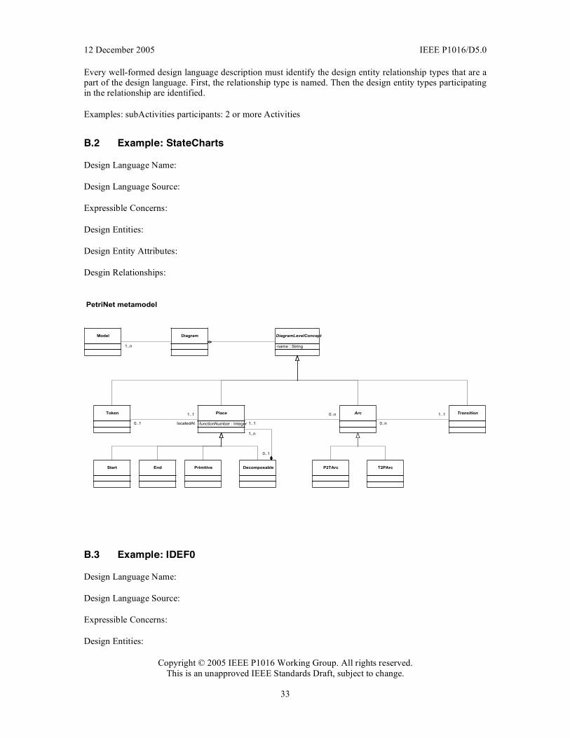
12 December 2005 IEEE P1016/D5.0
Copyright © 2005 IEEE P1016 Working Group. All rights reserved. This is an unapproved IEEE Standards Draft, subject to change.
33
Every well-formed design language description must identify the design entity relationship types that are a part of the design language. First, the relationship type is named. Then the design entity types participating in the relationship are identified.
Examples: subActivities participants: 2 or more Activities
B.2 Example: StateCharts
Design Language Name:
Design Language Source:
Expressible Concerns:
Design Entities:
Design Entity Attributes:
Desgin Relationships:
B.3 Example: IDEF0
Design Language Name:
Design Language Source:
Expressible Concerns:
Design Entities:
Place
-functionNumber : Integer
Transition
Primitive Decomposable
1..n
0..1
Token Arc
Start End
DiagramLevelConcept
-name : String
Model Diagram
1..n
1..1
0..n
0..n
1..1
P2TArc T2PArc
PetriNet metamodel
0..1
1..1
locatedAt
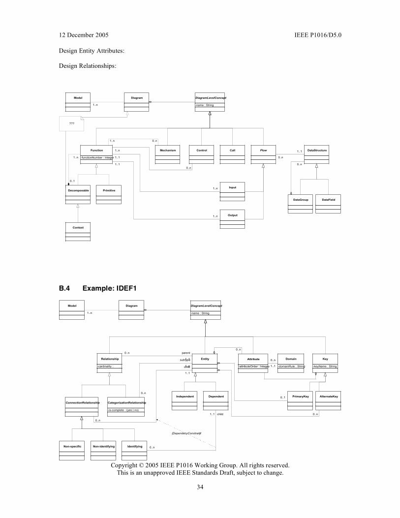
12 December 2005 IEEE P1016/D5.0
Copyright © 2005 IEEE P1016 Working Group. All rights reserved. This is an unapproved IEEE Standards Draft, subject to change.
34
Design Entity Attributes:
Design Relationships:
Function
-functionNumber : Integer
Flow
Input
Output
PrimitiveDecomposable
1..n
0..1
1..n
1..1
1..1
1..n
Mechanism Control
1..n 0..n
1..n
0..n
Context
DataGroup DataField
0..n
DiagramLevelConcept
-name : String
Model Diagram
1..n
DataStructure
0..n
1..1Call
???
B.4 Example: IDEF1
DiagramLevelConcept
-name : String
Model Diagram
1..n
Entity Attribute
-attributeOrder : Integer
Relationship
-cardinality :
ConnectionRelationship CategorizationRelationship
-is-complete : (yes | no)
0..n
1..1 child
0..n
Domain
-domainRule : String
0..n
1..11..n
0..n
subtype Key
-keyName : String
PrimaryKey AlternateKey
0..1
0..n
DependentIndependent
IdentifyingNon-identifying
1..1
0..n parent
Non-specific
0..n
1..1
child
{DependecyConstraint}

12 December 2005 IEEE P1016/D5.0
Copyright © 2005 IEEE P1016 Working Group. All rights reserved. This is an unapproved IEEE Standards Draft, subject to change.
35
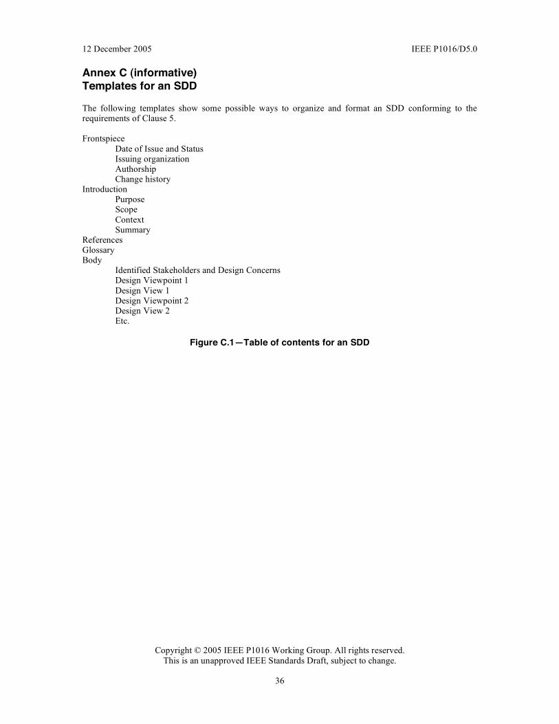
12 December 2005 IEEE P1016/D5.0
Copyright © 2005 IEEE P1016 Working Group. All rights reserved. This is an unapproved IEEE Standards Draft, subject to change.
36
Annex C (informative) Templates for an SDD
The following templates show some possible ways to organize and format an SDD conforming to the requirements of Clause 5. Frontspiece
Date of Issue and Status Issuing organization Authorship Change history
Introduction Purpose Scope Context Summary
References Glossary Body
Identified Stakeholders and Design Concerns Design Viewpoint 1 Design View 1 Design Viewpoint 2 Design View 2 Etc.
Figure C.1—Table of contents for an SDD