Embed Size (px)
Citation preview

Products Solutions Services
Brief Operating InstructionsProline t-mass T 150Thermal mass flowmeter
These Instructions are Brief Operating Instructions; they do notreplace the Operating Instructions included in the scope ofsupply.For detailed information, refer to the Operating Instructionsand other documentation on the CD-ROM provided or visit"www.endress.com/deviceviewer".
KA01155D/06/EN/01.1371237441
Table of contents Proline t-mass T 150
2 Endress+Hauser
Table of contents
1 Document information . . . . . . . . . . . . . . . . . . . . . . . . . . . . . . . . . . . . . . . . . . . . . . . . . . . . . . . . . . . 31.1 Symbols used . . . . . . . . . . . . . . . . . . . . . . . . . . . . . . . . . . . . . . . . . . . . . . . . . . . . . . . . . . . . . . . . . . . . . . . . 3
2 Basic safety instructions . . . . . . . . . . . . . . . . . . . . . . . . . . . . . . . . . . . . . . . . . . . . . . . . . . . . . . . . . 52.1 Requirements for the personnel . . . . . . . . . . . . . . . . . . . . . . . . . . . . . . . . . . . . . . . . . . . . . . . . . . . . . . . . . . . 52.2 Designated use . . . . . . . . . . . . . . . . . . . . . . . . . . . . . . . . . . . . . . . . . . . . . . . . . . . . . . . . . . . . . . . . . . . . . . . 52.3 Workplace safety . . . . . . . . . . . . . . . . . . . . . . . . . . . . . . . . . . . . . . . . . . . . . . . . . . . . . . . . . . . . . . . . . . . . . . 62.4 Operational safety . . . . . . . . . . . . . . . . . . . . . . . . . . . . . . . . . . . . . . . . . . . . . . . . . . . . . . . . . . . . . . . . . . . . . 62.5 Product safety . . . . . . . . . . . . . . . . . . . . . . . . . . . . . . . . . . . . . . . . . . . . . . . . . . . . . . . . . . . . . . . . . . . . . . . . 72.6 IT security . . . . . . . . . . . . . . . . . . . . . . . . . . . . . . . . . . . . . . . . . . . . . . . . . . . . . . . . . . . . . . . . . . . . . . . . . . . 7
3 Product description . . . . . . . . . . . . . . . . . . . . . . . . . . . . . . . . . . . . . . . . . . . . . . . . . . . . . . . . . . . . . . 83.1 Product design . . . . . . . . . . . . . . . . . . . . . . . . . . . . . . . . . . . . . . . . . . . . . . . . . . . . . . . . . . . . . . . . . . . . . . . 8
4 Incoming acceptance and product identification . . . . . . . . . . . . . . . . . . . . . . . . . . . . . . . . . . 94.1 Incoming acceptance . . . . . . . . . . . . . . . . . . . . . . . . . . . . . . . . . . . . . . . . . . . . . . . . . . . . . . . . . . . . . . . . . . . 94.2 Product identification . . . . . . . . . . . . . . . . . . . . . . . . . . . . . . . . . . . . . . . . . . . . . . . . . . . . . . . . . . . . . . . . . 10
5 Storage and transport . . . . . . . . . . . . . . . . . . . . . . . . . . . . . . . . . . . . . . . . . . . . . . . . . . . . . . . . . . . 115.1 Storage conditions . . . . . . . . . . . . . . . . . . . . . . . . . . . . . . . . . . . . . . . . . . . . . . . . . . . . . . . . . . . . . . . . . . . . 115.2 Transporting the product . . . . . . . . . . . . . . . . . . . . . . . . . . . . . . . . . . . . . . . . . . . . . . . . . . . . . . . . . . . . . . . 115.3 Packaging disposal . . . . . . . . . . . . . . . . . . . . . . . . . . . . . . . . . . . . . . . . . . . . . . . . . . . . . . . . . . . . . . . . . . . 12
6 Installation . . . . . . . . . . . . . . . . . . . . . . . . . . . . . . . . . . . . . . . . . . . . . . . . . . . . . . . . . . . . . . . . . . . . . 136.1 Installation conditions . . . . . . . . . . . . . . . . . . . . . . . . . . . . . . . . . . . . . . . . . . . . . . . . . . . . . . . . . . . . . . . . . 136.2 Mounting the measuring device . . . . . . . . . . . . . . . . . . . . . . . . . . . . . . . . . . . . . . . . . . . . . . . . . . . . . . . . . . 216.3 Post-installation check . . . . . . . . . . . . . . . . . . . . . . . . . . . . . . . . . . . . . . . . . . . . . . . . . . . . . . . . . . . . . . . . . 24
7 Electrical connection . . . . . . . . . . . . . . . . . . . . . . . . . . . . . . . . . . . . . . . . . . . . . . . . . . . . . . . . . . . . 257.1 Connection conditions . . . . . . . . . . . . . . . . . . . . . . . . . . . . . . . . . . . . . . . . . . . . . . . . . . . . . . . . . . . . . . . . . 257.2 Connecting the measuring device . . . . . . . . . . . . . . . . . . . . . . . . . . . . . . . . . . . . . . . . . . . . . . . . . . . . . . . . . 287.3 Ensuring the degree of protection . . . . . . . . . . . . . . . . . . . . . . . . . . . . . . . . . . . . . . . . . . . . . . . . . . . . . . . . 297.4 Post-connection check . . . . . . . . . . . . . . . . . . . . . . . . . . . . . . . . . . . . . . . . . . . . . . . . . . . . . . . . . . . . . . . . . 30
8 Operation options . . . . . . . . . . . . . . . . . . . . . . . . . . . . . . . . . . . . . . . . . . . . . . . . . . . . . . . . . . . . . . 318.1 Structure and function of the operating menu . . . . . . . . . . . . . . . . . . . . . . . . . . . . . . . . . . . . . . . . . . . . . . . . 318.2 Access to the operating menu via the local display . . . . . . . . . . . . . . . . . . . . . . . . . . . . . . . . . . . . . . . . . . . . 328.3 Access to the operating menu via the operating tool . . . . . . . . . . . . . . . . . . . . . . . . . . . . . . . . . . . . . . . . . . . 38
9 System integration . . . . . . . . . . . . . . . . . . . . . . . . . . . . . . . . . . . . . . . . . . . . . . . . . . . . . . . . . . . . . . 40
10 Commissioning . . . . . . . . . . . . . . . . . . . . . . . . . . . . . . . . . . . . . . . . . . . . . . . . . . . . . . . . . . . . . . . . . 4010.1 Function check . . . . . . . . . . . . . . . . . . . . . . . . . . . . . . . . . . . . . . . . . . . . . . . . . . . . . . . . . . . . . . . . . . . . . . 4010.2 Switching on the measuring device . . . . . . . . . . . . . . . . . . . . . . . . . . . . . . . . . . . . . . . . . . . . . . . . . . . . . . . . 4010.3 Setting the operating language . . . . . . . . . . . . . . . . . . . . . . . . . . . . . . . . . . . . . . . . . . . . . . . . . . . . . . . . . . 4110.4 Configuring the measuring device . . . . . . . . . . . . . . . . . . . . . . . . . . . . . . . . . . . . . . . . . . . . . . . . . . . . . . . . 4110.5 Defining the tag name . . . . . . . . . . . . . . . . . . . . . . . . . . . . . . . . . . . . . . . . . . . . . . . . . . . . . . . . . . . . . . . . . 4210.6 Protecting settings from unauthorized access . . . . . . . . . . . . . . . . . . . . . . . . . . . . . . . . . . . . . . . . . . . . . . . . 42
11 Diagnostic information and remedial measures . . . . . . . . . . . . . . . . . . . . . . . . . . . . . . . . . 44

Proline t-mass T 150 Document information
Endress+Hauser 3
1 Document information
1.1 Symbols used
1.1.1 Safety symbols
Symbol Meaning
DANGER
A0011189-EN
DANGER!This symbol alerts you to a dangerous situation. Failure to avoid this situation will result inserious or fatal injury.
WARNING
A0011190-EN
WARNING!This symbol alerts you to a dangerous situation. Failure to avoid this situation can result inserious or fatal injury.
CAUTION
A0011191-EN
CAUTION!This symbol alerts you to a dangerous situation. Failure to avoid this situation can result inminor or medium injury.
NOTICE
A0011192-EN
NOTICE!This symbol contains information on procedures and other facts which do not result in personalinjury.
1.1.2 Electrical symbols
Symbol Meaning
A0011197
Direct currentA terminal to which DC voltage is applied or through which direct current flows.
A0011198
Alternating currentA terminal to which alternating voltage is applied or through which alternating current flows.
A0017381
Direct current and alternating current• A terminal to which alternating voltage or DC voltage is applied.• A terminal through which alternating current or direct current flows.
A0011200
Ground connectionA grounded terminal which, as far as the operator is concerned, is grounded via a grounding system.
A0011199
Protective ground connectionA terminal which must be connected to ground prior to establishing any other connections.
A0011201
Equipotential connectionA connection that has to be connected to the plant grounding system: This may be a potentialequalization line or a star grounding system depending on national or company codes of practice.
Document information Proline t-mass T 150
4 Endress+Hauser
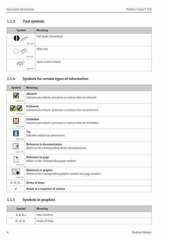
1.1.3 Tool symbols
Symbol Meaning
A0011220
Flat blade screwdriver
A0011221
Allen key
A0011222
Open-ended wrench
1.1.4 Symbols for certain types of information
Symbol Meaning
A0011182
AllowedIndicates procedures, processes or actions that are allowed.
A0011183
PreferredIndicates procedures, processes or actions that are preferred.
A0011184
ForbiddenIndicates procedures, processes or actions that are forbidden.
A0011193
TipIndicates additional information.
A0011194
Reference to documentationRefers to the corresponding device documentation.
A0011195
Reference to pageRefers to the corresponding page number.
A0011196
Reference to graphicRefers to the corresponding graphic number and page number.
, …, Series of steps
Result of a sequence of actions
1.1.5 Symbols in graphics
Symbol Meaning
1, 2, 3,... Item numbers
, …, Series of steps

Proline t-mass T 150 Basic safety instructions
Endress+Hauser 5
Symbol Meaning
A, B, C, ... Views
A-A, B-B, C-C, ... Sections
A0013441
Flow direction
- A0011187
Hazardous areaIndicates a hazardous area.
. A0011188
Safe area (non-hazardous area)Indicates a non-hazardous area.
2 Basic safety instructions
2.1 Requirements for the personnelThe personnel must fulfill the following requirements for its tasks:‣ Trained, qualified specialists must have a relevant qualification for this specific function
and task‣ Are authorized by the plant owner/operator‣ Are familiar with federal/national regulations‣ Before beginning work, the specialist staff must have read and understood the instructions
in the Operating Instructions and supplementary documentation as well as in thecertificates (depending on the application)
‣ Following instructions and basic conditions
2.2 Designated useApplication and mediaThe measuring device described in these Operating Instructions is intended only for flowmeasurement of liquids.Measuring devices for use in hazardous areas, in hygienic applications or in applicationswhere there is an increased risk due to process pressure, are labeled accordingly on thenameplate.To ensure that the measuring device remains in proper condition for the operation time:‣ Only use the measuring device in full compliance with the data on the nameplate and the
general conditions listed in the Operating Instructions and supplementary documentation.‣ Based on the nameplate, check whether the ordered device is permitted for the intended
use in the hazardous area (e.g. explosion protection, pressure vessel safety).‣ Use the measuring device only for media against which the process-wetted materials are
adequately resistant.‣ If the measuring device is not operated at atmospheric temperature, compliance with the
relevant basic conditions specified in the device documentation provided (on the CD-ROM)is absolutely essential.

Basic safety instructions Proline t-mass T 150
6 Endress+Hauser
Incorrect useNon-designated use can compromise safety. The manufacturer is not liable for damage causedby improper or non-designated use.
!WARNINGRisk of injury if the process connection and sensor gland are opened under pressure.‣ The process connection and the sensor gland should only be opened in an unpressurized
state.
NOTICEPenetration of dust and moisture when the transmitter housing is opened.‣ Only open the transmitter housing briefly, ensuring that no dust or moisture enters the
housing.
NOTICEDanger of breakage of the sensor due to corrosive or abrasive fluids!‣ Verify the compatibility of the process fluid with the sensor material.‣ Ensure the resistance of all fluid-wetted materials in the process.‣ Keep within the specified pressure and temperature range.
Verification for borderline cases:‣ For special fluids and fluids for cleaning, Endress+Hauser is glad to provide assistance in
verifying the corrosion resistance of fluid-wetted materials, but does not accept anywarranty or liability as minute changes in the temperature, concentration or level ofcontamination in the process can alter the corrosion resistance properties.
Residual risksThe external surface temperature of the housing can increase by max. 15 K due to the powerconsumption of the electronic components. Hot process fluids passing through the measuringdevice will further increase the surface temperature of the housing. The surface of the sensor,in particular, can reach temperatures which are close to the fluid temperature.Possible burn hazard due to fluid temperatures!‣ For elevated fluid temperature, ensure protection against contact to prevent burns.
2.3 Workplace safetyFor work on and with the device:‣ Wear the required personal protective equipment according to federal/national
regulations.
For welding work on the piping:‣ Do not ground the welding unit via the measuring device.
2.4 Operational safetyRisk of injury!‣ Operate the device in proper technical condition and fail-safe condition only.‣ The operator is responsible for interference-free operation of the device.

Proline t-mass T 150 Basic safety instructions
Endress+Hauser 7
2.5 Product safetyThis measuring device is designed in accordance with good engineering practice to meet state-of-the-art safety requirements, has been tested, and left the factory in a condition in which itis safe to operate.It meets general safety standards and legal requirements. It also complies with the ECdirectives listed in the device-specific EC Declaration of Conformity. Endress+Hauser confirmsthis by affixing the CE mark to the device.
2.6 IT securityWe only provide a warranty if the device is installed and used as described in the OperatingInstructions. The device is equipped with security mechanisms to protect it against anyinadvertent changes to the device settings.IT security measures in line with operators' security standards and designed to provideadditional protection for the device and device data transfer must be implemented by theoperators themselves.Endress+Hauser can be contacted to provide support in performing this task.
Product description Proline t-mass T 150
8 Endress+Hauser
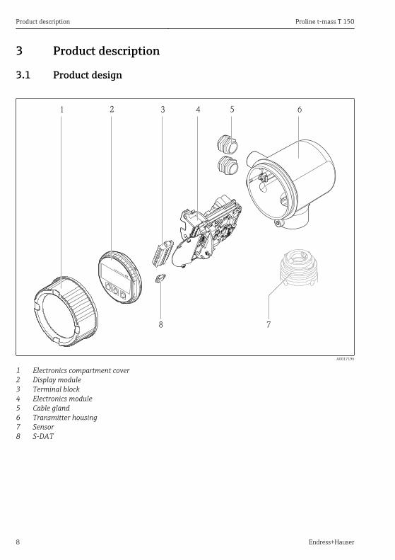
3 Product description
3.1 Product design
1
2
22
23
24
25
26
27
7
Esc
1 2 3 4 5 6
8
A0017196
1 Electronics compartment cover2 Display module3 Terminal block4 Electronics module5 Cable gland6 Transmitter housing7 Sensor8 S-DAT

Proline t-mass T 150 Incoming acceptance and product identification
Endress+Hauser 9
4 Incoming acceptance and product identification
4.1 Incoming acceptance
A0015502
1+
2
1+
2
A0013843
Are the order codes on thedelivery note (1) and on theproduct sticker (2) identical?
A0013695
A0015502
A0013698
Are the goods undamaged?
A0015502
A0013699
Do the nameplate data matchthe ordering information onthe delivery note?
A0015502
A0013697
Is the CD-ROM with theTechnical Documentation(depends on device version)and documents present?
• If one of the conditions is not satisfied, contact your Endress+Hauser Sales Center.• Depending on the device version, the CD-ROM might not be part of the delivery! In
such cases, the technical documentation is available via the Internet or via the Endress+Hauser Operations App, see the "Device documentation" section (→ 10).

Incoming acceptance and product identification Proline t-mass T 150
10 Endress+Hauser
4.2 Product identificationThe following options are available for identification of the measuring device:• Nameplate specifications• Order code with breakdown of the device features on the delivery note• Enter serial numbers from nameplates in W@M Device Viewer
(www.endress.com/deviceviewer): All information about the measuring device is displayed.• Enter the serial number from the nameplates into the Endress+Hauser Operations App or
scan the 2-D matrix code (QR code) on the nameplate with the Endress+Hauser OperationsApp: all the information for the measuring device is displayed.
Order code:
Ext. ord. cd.:
Ser. no.:
1
2
3
4
A0021952
1 Example of a nameplate
1 Order code2 Serial number (Ser. no.)3 Extended order code (Ext. ord. cd.)4 2-D matrix code (QR code)
For detailed information on the breakdown of the specifications on the nameplate, seethe Operating Instructions for the device (→ 10).
4.2.1 Device documentationAll devices are supplied with Brief Operating Instructions. These Brief OperatingInstructions are not a substitute for the Operating Instructions pertaining to the device!
Detailed information about the device can be found in the Operating Instructions and theother documentation:• On the CD-ROM supplied (is not included in the delivery for all device versions).• Available for all device versions via:
– Internet: www.endress.com/deviceviewer– Smart phone/tablet: Endress+Hauser Operations App
The information required to retrieve the documentation can be found on the nameplate of thedevice (→ 1, 10).

Proline t-mass T 150 Storage and transport
Endress+Hauser 11
Technical documentation can also be downloaded from the Download Area of theEndress+Hauser web site: www.endress.com→ Download. However this technicaldocumentation applies to a particular instrument family and is not assigned to a specificdevice.
W@M Device Viewer1. Launch the W@M Device Viewer: www.endress.com/deviceviewer2. Enter the serial number (Ser. no.) of the device: see nameplate (→ 1, 10).
All the associated documentation is displayed.
Endress+Hauser Operations AppThe Endress+Hauser Operations App is available both for android smart phones (GooglePlay store) and for iPhones and iPads (App Store).
Via the serial number:1. Launch the Endress+Hauser Operations App.2. Enter the serial number (Ser. no.) of the device: see nameplate (→ 1, 10).
All the associated documentation is displayed.
Via the 2-D matrix code (QR code):1. Launch the Endress+Hauser Operations App.2. Scan the 2-D matrix code (QR code) on the nameplate (→ 1, 10).
All the associated documentation is displayed.
5 Storage and transport
5.1 Storage conditionsObserve the following notes for storage:• Store in original packaging.• Do not remove the protection cap mounted on the transducer.• Protect from direct sunlight.• Select a storage location where moisture cannot collect in the measuring device.• Storage temperature: –40 to +60 °C (–40 to +140 °F)• Store in a dry and dust-free place.• Do not store outdoors.
5.2 Transporting the productObserve the following notes during transport:• Transport the measuring device to the measuring point in the original packaging.• Do not remove the protection cap mounted on the transducer. It prevents mechanical
damage and contamination in the measuring tube.

Storage and transport Proline t-mass T 150
12 Endress+Hauser
5.3 Packaging disposalFor detailed information about disposing of the packaging materials, refer to theOperating Instructions for the device on the CD-ROM provided

Proline t-mass T 150 Installation
Endress+Hauser 13
6 Installation
6.1 Installation conditionsFor mechanical reasons and to protect the pipe, support is recommended for heavy sensors(e.g. with a hot-tap retractable assembly).
6.1.1 Mounting position
OrientationThe direction of the arrow on the sensor body helps you to install the sensor according to theflow direction (direction of medium flow through the piping).For detailed information on aligning with the flow direction: (→ 19)
Installation is generally not recommended in the event of high vibrations or unstableinternal fittings.
Orientation Recommendation
Vertical orientation
A0017337
1)
Horizontal orientation, transmitter head up
A0015589
Horizontal orientation, transmitter headdown
A0015590
1) Partially filled pipe detection is not possible in this orientation.
For detailed information about partially filled pipe detection, refer to the OperatingInstructions for the device on the CD-ROM provided
PipesThe measuring device must be professionally installed, and the following points must beobserved:

Installation Proline t-mass T 150
14 Endress+Hauser
Further information → ISO standard 14511
A0005103
Correctly aligned flanges and seals
Insertion depth
Standard versionOrder code for "Insertion Length", option L5 "110mm 4"" and L6 "330mm 13""
NOTICEMetal clamping ferrules undergo plastic deformation during the initial installation.As a result the insertion depth is fixed after initial installation and the clamping ferrules canno longer be replaced.‣ Pay attention to information on preconditions and on determining the insertion depth.‣ Check the insertion depth closely before tightening the clamping ferrules.
Preconditions
AB
D
C
110
110
A0022049
A Fixed insertion depth 8 mm (0.31 in) ±2 mm (0.08 in)B Pipe wall thicknessC Mounting boss heightD Socket height (incl. coupling)
1. Determine pipe wall thickness (B).2. Measure socket height (D).

Proline t-mass T 150 Installation
Endress+Hauser 15
NOTE! Mounting for the first time: Tighten thread adapter nut of the couplinghand tight.
3. Observe the maximum socket height D. NOTE! The pipe wall thickness (B) and socket height (D) may not exceed the
permitted height.B + D may not be greater than 102 mm (4.02 in).
4. If a mounting boss is used, pay attention to mounting boss height C. NOTE! The pipe wall thickness (B) and mounting boss height (C) may not exceed
the permitted height.B + C may not be greater than 53 mm (2.09 in).
Determining the insertion depth before mounting for the first time‣ For all nominal diameters: 8 + B + D -1
Controlling the insertion depth after mounting‣ For all nominal diameters: 8 + B + D
Hygienic versionOrder code for "Insertion Length", option LH "Hygienic version"
Factory lengthOrder code for "Insertion Tube Material; Sensor", option BB "Stainless steel, factory length,0.8μm, mechanically polished" and option BC "Stainless steel, factory length, 0.4μm,mechanically polished"
NOTICECertain dimensions are required to comply with the factory length.‣ Pay attention to information in the dimension drawings.
Installation Proline t-mass T 150
16 Endress+Hauser
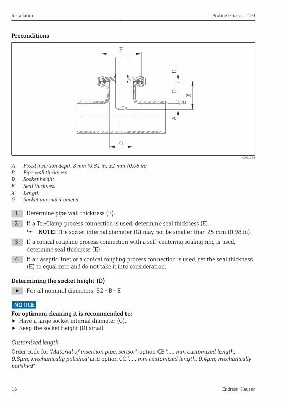
Preconditions
G
F
DE
A
XB
A0022058
A Fixed insertion depth 8 mm (0.31 in) ±2 mm (0.08 in)B Pipe wall thicknessD Socket heightE Seal thicknessX LengthG Socket internal diameter
1. Determine pipe wall thickness (B).2. If a Tri-Clamp process connection is used, determine seal thickness (E).
NOTE! The socket internal diameter (G) may not be smaller than 25 mm (0.98 in).3. If a conical coupling process connection with a self-centering sealing ring is used,
determine seal thickness (E).4. If an aseptic liner or a conical coupling process connection is used, set the seal thickness
(E) to equal zero and do not take it into consideration.
Determining the socket height (D)‣ For all nominal diameters: 32 - B - E
NOTICEFor optimum cleaning it is recommended to:‣ Have a large socket internal diameter (G).‣ Keep the socket height (D) small.
Customized lengthOrder code for "Material of insertion pipe; sensor", option CB "….. mm customized length,0.8μm, mechanically polished" and option CC "….. mm customized length, 0.4μm, mechanicallypolished"

Proline t-mass T 150 Installation
Endress+Hauser 17
Order code for "Material of insertion pipe; sensor", option CD "….. inch customized length,0.8μm, mechanically polished" and option CE "….. inch customized length, 0.4μm, mechanicallypolished"
NOTICEWhen ordering the customized length, it is necessary to declare the sensor length withthe following decimal accuracies:‣ SI units (mm): With a minimum of 1 decimal place. Example: 43.3 mm‣ US units (in): With a minimum of 2 decimal places. Example: 17.05 in‣ When ordering, a maximum of 3 decimal places can be declared.
NOTICECertain dimensions are required for determining the customized length.‣ Pay attention to information in the dimension drawings.
Preconditions
G
F
DE
A
XB
A0022058
A Fixed insertion depth 8 mm (0.31 in) ±2 mm (0.08 in)B Pipe wall thicknessD Socket heightE Seal thicknessX LengthG Socket internal diameter
1. Determine pipe wall thickness (B).2. Measure socket height (D).3. Observe the maximum socket height D.
NOTE! The pipe wall thickness (B) and socket height (D) may not exceed thepermitted height.B + D may not be greater than 77 mm (3.03 in).

Installation Proline t-mass T 150
18 Endress+Hauser
4. If a Tri-Clamp process connection is used, determine seal thickness (E). NOTICE! The pipe wall thickness (B), socket height (D) and sealing thickness (E)
may not exceed the permitted height.B + D + E may not be greater than 77 mm (3.03 in).
5. If a conical coupling process connection with a self-centering sealing ring is used,determine seal thickness (E). NOTE! The pipe wall thickness (B), socket height (D) and sealing thickness (E) may
not exceed the permitted height.B + D + E may not be greater than 77 mm (3.03 in).
6. If an aseptic liner or a conical coupling process connection is used, set the seal thickness(E) to equal zero and do not take it into consideration. NOTE! The pipe wall thickness (B) and socket height (D) may not exceed the
permitted height.B + D may not be greater than 77 mm (3.03 in).
Determining the customized length‣ For all nominal diameters: 8 + B + D + E
Installation conditions for nipples
90° (±3°)
D
90° (±3°)
A0011843
2 Installation conditions for mounting bosses and threadolets
D = 20.0 mm ± 0.5 mm (0.79 in ± 0.02 in)
‣ In the case of weld-in couplings with PEEK clamping ferrules, remove the clampingferrules before you commence welding to avoid heat damage from the welding process.

Proline t-mass T 150 Installation
Endress+Hauser 19
Alignment with flow direction
Insertion version
90° ( 7°)±
110
A0022051
1. Check and ensure that the sensor on the pipe is aligned at a 90° angle to the direction offlow (as shown in the graphic).
2. Rotate the sensor so that the arrow marking on the sensor body corresponds to thedirection of flow.
3. Align the scale to the pipe axis.
Inlet and outlet runsFor the dimensions and installation lengths of the device, see the "Technical Information"document, "Mechanical construction" section

Installation Proline t-mass T 150
20 Endress+Hauser
20 × DN 5 × DN
5 × DN35 × DN
35 × DN5 × DN 5 × DN
5 × DN35 × DN5 × DN50 × DN
20 × DN
1
4
2
6
3
5
A0022381
1 reduction2 expansion3 90 ° elbow or T-section4 2 × 90° elbow5 Control valve6 2 × 90 ° elbow 3-dimensional
6.1.2 Requirements from environment and process
Ambient temperature range
Measuring device –40 to +60 °C (–40 to +140 °F)
Local display –20 to +60 °C (–4 to +140 °F), the readability of the display may be impaired attemperatures outside the temperature range.
‣ If operating outdoors:Avoid direct sunlight, particularly in warm climatic regions.
System pressureNOTICE
Depending on version:Observe information on nameplate.‣ Max. 40 bar g (580 psi g)
!WARNINGIf the coupling is opened incorrectly under full process pressure, the sensor will shootout. Therefore it must be ensured that the sensor does not accelerate to a dangerous exitvelocity.‣ Use a safety chain for pressures > 4.5 bar (65.27 psi) in combination with PEEK clamping
ferrules .

Proline t-mass T 150 Installation
Endress+Hauser 21
!WARNINGThe sensor is exposed to high temperatures.Risk of burns from hot surfaces or leaking medium!‣ Before commencing work: allow the system and measuring device to cool to a safe
temperature.
Thermal insulationThe maximum possible thickness of the thermal insulation layer is:Order code for "Insertion Length", option L5 "110mm 4"": 100 mm (3.94 in)The following is recommended for thicker insulation layers:Order code for "Insertion Length", option L6 "330mm 13"": 320 mm (12.6 in)
A0015763
6.2 Mounting the measuring device
6.2.1 Required tools
For transmitterFor turning the transmitter housing (in increments of 90°): Allen screw 4 mm (0.15 in)
For sensor
6.2.2 Preparing the measuring device1. Remove all remaining transport packaging.2. Remove stick-on label on the electronics compartment cover.

Installation Proline t-mass T 150
22 Endress+Hauser
6.2.3 Mounting the measuring device
!WARNINGDanger due to improper process sealing!‣ Ensure that the gaskets are clean and undamaged.‣ Ensure that the correct sealing material has been used (e.g. Teflon tape for NPT ¾").‣ Install the gaskets correctly.
230
220
210
200
190
180
9
8
7
30 mm
1.
2.3.
x
A0017331
3 Engineering unit mm (in)
x number of turns to tighten
1. Ensure that the direction of the arrow on the sensor matches the flow direction of themedium. Ensure the insertion depth (→ 14)and alignment (→ 19) are correct.
2. Tighten thread adapter nut hand tight.3. Depending on the process connection:
Tighten thread adapter nut with x turns: For PEEK clamping ferrules continue with Step 4.
For metallic clamping ferrules continue with Step 5.For hygienic process connections continue with Step 6.
4. For PEEK clamping ferrules:Mounting for the first time: tighten thread adapter nut with 1¼ turns (→ 22).Repeat mounting: tighten thread adapter nut with 1 turn (→ 22). NOTE! If strong vibrations can be expected, tighten the thread adapter nut with 1½
turns (→ 22) when mounting for the first time.5. For metallic clamping ferrules:
Mounting for the first time: tighten thread adapter nut with 1¼ turns (→ 22).Repeat mounting: tighten thread adapter nut with ¼ turn (→ 22).
6. For hygienic process connections:Make sure the connection is aligned correctly and tighten the union nut or clamp forTri-Clamp (not included in the delivery).

Proline t-mass T 150 Installation
Endress+Hauser 23
7. Install the measuring device or turn the transmitter housing so that the cable entries donot point upwards.
A0013964
6.2.4 Turning the transmitter housingTo provide easier access to the connection compartment or display module, the transmitterhousing can be turned clockwise or counterclockwise to 4 indexed positions by a maximum of2× 90°:
max. 2 × 90°
4 mm 4 mm
1.
2.
3.
A0017227
4 Engineering unit mm (in)

Installation Proline t-mass T 150
24 Endress+Hauser
6.2.5 Turning the display module
Esc
A0017228
6.3 Post-installation check
Is the device undamaged (visual inspection)?
Does the measuring device conform to the measuring point specifications?
For example:• Process temperature• Process pressure (refer to the chapter on "Material load curves" of the "Technical Information"
document on the CD-ROM provided)• Ambient temperature (→ 20)• Measuring range
Has the correct orientation for the sensor been selected (→ 13)?
• According to sensor type• According to medium properties• According to medium temperature• According to process pressure
Does the arrow on the sensor match the direction of flow of the medium through the piping (→ 13)?
Have sufficient inlet and outlet runs been provided upstream and downstream of the measuring point?
Correctly aligned in the direction of flow?
Is the device adequately protected from precipitation and direct sunlight?
Is the device protected against overheating?
Is the device protected against excessive vibrations?
Check liquid properties (e.g. purity, cleanness).
Are the measuring point identification and labeling correct (visual inspection)?
Proline t-mass T 150 Electrical connection
Endress+Hauser 25
7 Electrical connection
7.1 Connection conditions
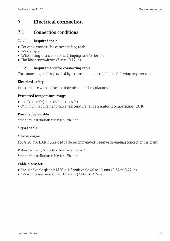
7.1.1 Required tools• For cable entries: Use corresponding tools• Wire stripper• When using stranded cables: Crimping tool for ferrule• Flat blade screwdriver≤3 mm (0.12 in)
7.1.2 Requirements for connecting cableThe connecting cables provided by the customer must fulfill the following requirements.
Electrical safetyIn accordance with applicable federal/national regulations.
Permitted temperature range• –40 °C (–40 °F) to ≥ +80 °C (+176 °F)• Minimum requirement: cable temperature range ≥ ambient temperature +20 K
Power supply cableStandard installation cable is sufficient.
Signal cable
Current outputFor 4-20 mA HART: Shielded cable recommended. Observe grounding concept of the plant.
Pulse/frequency/switch output, status inputStandard installation cable is sufficient.
Cable diameter• Included cable glands: M20 × 1.5 with cable 6 to 12 mm (0.24 to 0.47 in)• Wire cross-sections 0.5 to 1.5 mm2 (21 to 16 AWG)

Electrical connection Proline t-mass T 150
26 Endress+Hauser
7.1.3 Terminal assignment
Transmitter
Connection version 4-20 mA HART, pulse/frequency/switch output, status input
5
1
2
3
12
23
22
24
25
26
27
4
A0017178
1 Supply voltage2 Status input3 Signal transmission: pulse/frequency/switch output4 Signal transmission: 4-20 mA HART5 Ground terminal for cable shield
Supply voltage
Order code for"Power supply"
Terminal numbers
1 (L+) 1) 2 (L-) 1)
Option D DC 18 to 30 V
1) Securely tighten the screws of the terminal. Recommended torque: 0.5 Nm.
Signal transmission
Order codefor"Output,input"
Terminal numbers
Output 1 Output 2 Input
26 (+) 1) 27 (-) 1) 24 (+) 1) 25 (-) 1) 22 (+) 1) 23 (-) 1)
Option A 4-20 mA HART (active) - -
Option B 4-20 mA HART (active) Pulse/frequency/switch output(passive)
-

Proline t-mass T 150 Electrical connection
Endress+Hauser 27
Order codefor"Output,input"
Terminal numbers
Output 1 Output 2 Input
26 (+) 1) 27 (-) 1) 24 (+) 1) 25 (-) 1) 22 (+) 1) 23 (-) 1)
Option K - Pulse/frequency/switch output(passive)
-
Option Q 4-20 mA HART (active) Pulse/frequency/switch output(passive)
Status input
1) Securely tighten the screws of the terminal. Recommended torque: 0.5 Nm.
7.1.4 Pin assignment of the connector
Supply voltage
Supply voltage for all communication types (on the device side)
1
2
4
3
5
A0016809
Pin Assignment Coding Plug/socket1 L+ DC24 V A Plug2 + Status input3 - Status input4 L- DC24 V5 Grounding/shielding
4-20 mA HART with pulse/frequency/switch output
4-20 mA HART with pulse/frequency/switch output (on the device side)
3
2
4
1
5
A0016810
Pin Assignment Coding Plug/socket1 + 4-20 mA HART (active) A Socket2 - 4-20 mA HART (active)3 + Pulse/frequency/switch output (passive)4 - Pulse/frequency/switch output (passive)5 Grounding/shielding
7.1.5 Requirements for the supply unit
Supply voltageDC 24 V (18 to 30 V)The power supply circuit must comply with SELV/PELV requirements.

Electrical connection Proline t-mass T 150
28 Endress+Hauser
Load0 to 750 Ω, depending on the external supply voltage of the power supply unit
7.1.6 Preparing the measuring device1. Remove dummy plug if present.2. NOTICE! Insufficient sealing of the housing. Operational reliability of the measuring
device could be defeated. Use suitable cable glands corresponding to the degree ofprotection.If measuring device is delivered without cable glands:Provide suitable cable gland for corresponding connecting cable.
3. If measuring device is delivered with cable glands:Observe cable specification .
7.2 Connecting the measuring deviceNOTICE
Limitation of electrical safety due to incorrect connection!‣ SELV/PELV-compliant 24 V DC (18 to 30 V) power supply.‣ 4 to 20 mAHART active‣ Maximum output values: DC 24V, 22 mA, load0 to 750 Ω

Proline t-mass T 150 Electrical connection
Endress+Hauser 29
7.2.1 Connecting the cables
E+–
1
2
22
23
24
25
26
27
10 (0.4)
3 (0.12)
1
2
22
23
24
25
26
27
24 mm
1.
2.
3.
4.
5.
7.
8.
A0017250
5 Engineering unit mm (in)
‣ NOTICE! Housing degree of protection voided due to insufficient sealing of the housing.Screw in the thread without using any lubricant. The threads on the cover are coatedwith a dry lubricant.Reverse the removal procedure to reassemble the transmitter.
For HART communication: When connecting the cable shielding to the ground terminal,observe the grounding concept of the facility.
7.3 Ensuring the degree of protectionThe measuring device fulfills all the requirements for the IP66 and IP67 (Type 4X enclosure)degree of protection.
To guarantee IP 66 and IP 67 degree of protection (Type 4X enclosure), carry out thefollowing steps after the electrical connection:

Electrical connection Proline t-mass T 150
30 Endress+Hauser
1. Check whether the housing seals of the connection and electronics compartment areclean and inserted correctly. Dry, clean or replace the seals if necessary.
2. Tighten all housing screws and screw covers.3. Firmly tighten the cable glands.4. To ensure that moisture does not enter the cable entry, route the cable so that it loops
down before the cable entry ("water trap").
A0013960
5. Insert dummy plugs into unused cable entries.
7.4 Post-connection check
Are cables or the device undamaged (visual inspection)?
Are the power supply and signal cables correctly connected?
Does the supply voltage correspond to the specifications in the connection diagram?
Do the cables comply with the requirements ?
Do the cables have adequate strain relief? Are they routed securely?
Is the cable type route completely isolated? Without loops and cross-overs?
Are all the screw terminals firmly tightened?
Are all the cable glands installed, firmly tightened and leak-tight? Cable run with "water trap"?(→ 25)
Does the supply voltage match the specifications on the transmitter nameplate ?
Is the terminal assignment correct ?
If supply voltage is present, is the device ready for operation and do values appear on the displaymodule?
Are all housing covers installed and firmly tightened?

Proline t-mass T 150 Operation options
Endress+Hauser 31
8 Operation options
8.1 Structure and function of the operating menu
8.1.1 Structure of the operating menu
!
Expert
Operating menu for experts
Language
Operation
Setup
Diagnostics
Operating menu for operators and maintenancesO
pe
rato
r
Ma
inte
na
nce
task
-ori
en
ted
fun
ctio
n-o
rie
nte
d
Ex
pe
rt
A0014058-EN
6 Schematic structure of the operating menu
8.1.2 Operating philosophyThe individual parts of the operating menu are assigned to certain user roles. Each user rolecorresponds to typical tasks within the device lifecycle.
For detailed information about the operating philosophy of the instrument, refer to theOperating Instructions for the device on the CD-ROM provided
Operation options Proline t-mass T 150
32 Endress+Hauser
8.2 Access to the operating menu via the local display
5
4ABC_ DEFG
UserHIJK
LMNO PQRS TUVW
XYZ Aa1
2.1
2.2
2.4
2.5
2.3
2.6
2 X X X X X XX
l/s
19.184 mA
12.5
3.1
3.2
Ã
Español
Français
Language
EnglishDeutsch
31.1
1.3
1.5
1.6ESC
E
X X X X X XX
20.50S
mA
1.4
1.7
1.2
1
3 40 1 295 6 87
30
A0014013
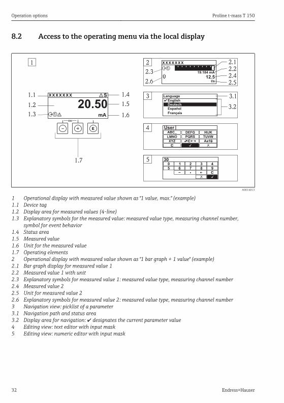
1 Operational display with measured value shown as "1 value, max." (example)1.1 Device tag1.2 Display area for measured values (4-line)1.3 Explanatory symbols for the measured value: measured value type, measuring channel number,
symbol for event behavior1.4 Status area1.5 Measured value1.6 Unit for the measured value1.7 Operating elements2 Operational display with measured value shown as "1 bar graph + 1 value" (example)2.1 Bar graph display for measured value 12.2 Measured value 1 with unit2.3 Explanatory symbols for measured value 1: measured value type, measuring channel number2.4 Measured value 22.5 Unit for measured value 22.6 Explanatory symbols for measured value 2: measured value type, measuring channel number3 Navigation view: picklist of a parameter3.1 Navigation path and status area3.2 Display area for navigation: designates the current parameter value4 Editing view: text editor with input mask5 Editing view: numeric editor with input mask

Proline t-mass T 150 Operation options
Endress+Hauser 33
8.2.1 Operational display
Status area
Status signals
A0013956 A0013959 A0013958 A0013957
Failure Function check Out of specification Maintenance requiredDiagnostic behavior Locking Communication
A0013961 A0013962 A0013963 A0013965
Alarm Warning Device locked Remote operation enabled
Display area
Measured variablesSymbol Meaning
A0013711
Volume flow
A0013710
Mass flow
A0013947
Temperature
A0013943
Totalizer
A0013945
Current output
A0017270
Status input
Symbols for measurement channel numbers
A0016325
Measurement channel 1 to 4
The measurement channel number is displayed only if more than one channel is present for the same measuredvariable type.Symbols for diagnostic behaviorThe diagnostic behavior pertains to a diagnostic event that is relevant to the displayed measured variable.For more information about the symbols, refer to the "Status area" section

Operation options Proline t-mass T 150
34 Endress+Hauser
8.2.2 Navigation view
Status areaThe following appears in the status area of the navigation view in the top right corner:• In the submenu
– The direct access code for the parameter you are navigating to (e.g. 0022-1)– If a diagnostic event is present, the diagnostic behavior and status signal
• In the wizardIf a diagnostic event is present, the diagnostic behavior and status signal
Display area
Icons for menus
A0013973 A0013974 A0013975 A0013966
Display/operat. Setup Diagnostics ExpertIcons for submenus, wizards, parameters Lock symbols
A0013967 A0013968 A0013972 A0013963
Submenu Wizard Parameters within a wizard Parameter locked
8.2.3 Editing view
Input mask
Operating symbols in the numeric editor
A0013985 A0016621 A0013986
Confirms selection. Moves the input position one positionto the left.
Exits the input without applying thechanges.
.
A0016619
–
A0016620 A0014040
Inserts decimal separator at the inputposition.
Inserts minus sign at the inputposition.
Clears all entered characters.
Operating symbols in the text editor
A0013985 A0013987 A0013986
Confirms selection. Switches to the selection of thecorrection tools.
Exits the input without applying thechanges.
A0014040
Aa1 A0013981
Clears all entered characters. Toggle• Between upper-case and lower-case
letters• For entering numbers• For entering special characters
Proline t-mass T 150 Operation options
Endress+Hauser 35
Correction symbols under
A0013989 A0013990 A0013991 A0013988
Clears all entered characters. Moves the input positionone position to the left.
Moves the input positionone position to the right.
Deletes one characterimmediately to the left of
the input position.
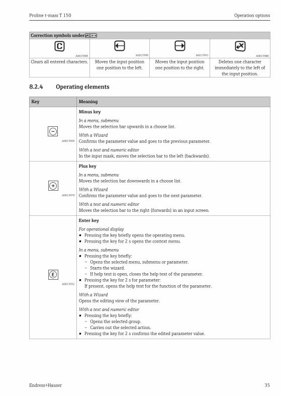
8.2.4 Operating elements
Key Meaning
A0013969
Minus key
In a menu, submenuMoves the selection bar upwards in a choose list.
With a WizardConfirms the parameter value and goes to the previous parameter.
With a text and numeric editorIn the input mask, moves the selection bar to the left (backwards).
A0013970
Plus key
In a menu, submenuMoves the selection bar downwards in a choose list.
With a WizardConfirms the parameter value and goes to the next parameter.
With a text and numeric editorMoves the selection bar to the right (forwards) in an input screen.
A0013952
Enter key
For operational display• Pressing the key briefly opens the operating menu.• Pressing the key for 2 s opens the context menu.
In a menu, submenu• Pressing the key briefly:
– Opens the selected menu, submenu or parameter.– Starts the wizard.– If help text is open, closes the help text of the parameter.
• Pressing the key for 2 s for parameter:If present, opens the help text for the function of the parameter.
With a WizardOpens the editing view of the parameter.
With a text and numeric editor• Pressing the key briefly:
– Opens the selected group.– Carries out the selected action.
• Pressing the key for 2 s confirms the edited parameter value.

Operation options Proline t-mass T 150
36 Endress+Hauser
Key Meaning
+
A0013971
Escape key combination (press keys simultaneously)
In a menu, submenu• Pressing the key briefly:
– Exits the current menu level and takes you to the next higher level.– If help text is open, closes the help text of the parameter.
• Pressing the key for 2 s returns you to the operational display ("home position").
With a WizardExits the wizard and takes you to the next higher level.
With a text and numeric editorCloses the text or numeric editor without applying changes.
+
A0013953
Minus/Enter key combination (press the keys simultaneously)
Reduces the contrast (brighter setting).
+
A0013954
Plus/Enter key combination (press and hold down the keys simultaneously)
Increases the contrast (darker setting).
++
A0013955
Minus/Plus/Enter key combination (press the keys simultaneously)
For operational displayEnables or disables the keypad lock.
8.2.5 Calling up help textHelp text is available for some parameters and can be called up from the navigation view. Thehelp text provides a brief explanation of the parameter function and thereby supports swiftand safe commissioning.
Calling up and closing the help textThe user is in the navigation view and the selection bar is on a parameter.
1. Press for 2 s. The help text for the selected parameter opens.
2. Press + simultaneously. The help text is closed.

Proline t-mass T 150 Operation options
Endress+Hauser 37
8.2.6 User roles and related access authorizationThe two user roles "Operator" and "Maintenance" have different write access to the parametersif the customer defines a user-specific access code. This protects the device configuration viathe local display from unauthorized access .
Access authorization to parameters
User role Read access Write access
Without access code(from the factory)
With access code Without access code(from the factory)
With access code
Operator -- 1)
Maintenance
1) Despite the defined access code, certain parameters can always be modified and thus are excepted from the writeprotection, as they do not affect the measurement. Refer to the "Write protection via access code" section
For detailed information about parameters which can always be modified, refer to theOperating Instructions for the device on the CD-ROM provided
If an incorrect access code is entered, the user obtains the access rights of the "Operator" role.The user role with which the user is currently logged on is indicated by the Access statusdisplay parameter. Navigation path: Operation menu →Access status displayparameter
8.2.7 Disabling write protection via access codeIf the -symbol appears on the local display in front of a parameter, the parameter is write-protected by a user-specific access code and its value cannot be changed at the moment usingthe local display .
The locking of the write access via local operation can be disabled by entering the customer-defined access code via the respective access option.
1. After you press , the input prompt for the access code appears.2. Enter the access code.
The -symbol in front of the parameters disappears; all previously write-protectedparameters are now re-enabled.
8.2.8 Enabling and disabling the keypad lockThe keypad lock makes it possible to block access to the entire operating menu via localoperation. As a result, it is no longer possible to navigate through the operating menu orchange the values of individual parameters. Users can only read the measured values on theoperational display.
Local operation with mechanical push buttons (display module SD02)Display module SD02: order characteristic "Display; Operation", option C

Operation options Proline t-mass T 150
38 Endress+Hauser
The keypad lock is switched on and off in the same way:
Switching on the keypad lock
‣ The device is in the measured value display.Press the + + keys simultaneously. The message Keylock on appears on the display: The keypad lock is switched on.
Switching off the keypad lock
‣ The keypad lock is switched on.Press the + + keys simultaneously. The message Keylock off appears on the display: The keypad lock is switched off.
8.3 Access to the operating menu via the operating toolFor detailed information about access to the operating menu via operating tool, refer tothe Operating Instructions for the device on the CD-ROM provided
8.3.1 Via HART protocolThis communication interface is present in the following device version:• Order code for "Output", option A: 4-20 mA HART• Order code for "Output", option B: 4-20 mA HART, pulse/frequency/switch output• Order code for "Output", option Q: 4-20 mA HART, pulse/frequency/switch output, status
input

Proline t-mass T 150 Operation options
Endress+Hauser 39
1 2 3 5
4 6
7
A0017373
7 Options for remote operation via HART protocol
1 Control system (e.g. PLC)2 Field Communicator 4753 Computer with operating tool (e.g. FieldCare, AMS Device Manager, SIMATIC PDM)4 Commubox FXA195 (USB)5 Field Xpert SFX350 or SFX3706 VIATOR Bluetooth modem with connecting cable7 Transmitter

System integration Proline t-mass T 150
40 Endress+Hauser
8.3.2 Via service interface (CDI)
1 2 3
E+–
A0017253
1 Service interface (CDI) of the measuring device2 Commubox FXA2913 Computer with "FieldCare" operating tool with COM DTM "CDI Communication FXA291"
9 System integrationFor system integration, see the Operating Instructions for the device (→ 10).
10 Commissioning
10.1 Function checkBefore commissioning the device, make sure that the post-installation and post-connectionchecks have been performed.• "Post-installation check" checklist (→ 24)• "Post-connection check" checklist
10.2 Switching on the measuring deviceAfter a successful function check, switch on the measuring device.After a successful startup, the local display switches automatically from the startup display tothe measured value display.

Proline t-mass T 150 Commissioning
Endress+Hauser 41
If nothing appears on the local display or a diagnostic message is displayed, refer to thedevice's operating instructions which can be found on the CD-ROM supplied with thedevice.
10.3 Setting the operating languageFactory setting: English or ordered local language
X X X X X X XX X
20.50
Operation
Setup
Main menu 0104-1
LanguageEnglish
Español
Français
Language
EnglishDeutsch
Ã
0104-1
Ã
Español
Français
Language
EnglishDeutsch
0104-1
Betrieb
Setup
Hauptmenü
SpracheDeutsch
0104-1
XXXX
A0013996
10.4 Configuring the measuring deviceThe Setup menu contains all the parameters that are needed for standard measuringoperation.Navigation"Setup" menu
Overview "Setup" menu
Options Meaning

Commissioning Proline t-mass T 150
42 Endress+Hauser
Device tag Enter the name for the measuring point.Temperature Displays the temperature currently measured.Pipe inner diameter Enter the inner diameter of the pipe.Installation factor Enter the factor to adjust the installation conditions.Assign status input Select the function for the status input.Assign current output Select process variable for current output.4 mA value Enter 4 mA value.20 mA value Enter 20 mA value.Operating mode Specify the output as a pulse, frequency or switch output.Assign frequency output Select the process variable for the frequency output.Measuring value at minimum frequency Enter the measured value at the minimum frequency.Measuring value at maximum frequency Specify the measured value at maximum frequency.Switch output function Select the function for the switch output.Assign limit Select the process variable for the limit function.Switch-off value Enter the measured value for the switch-off value.Switch-on value Enter the measured value for the switch-on value.Assign status Select the device status for the switch output.Assign diagnostic behavior Select the diagnostic behavior for the switch output.Assign pulse output Select the process variable for the pulse output.Value per pulse Enter the measured value for the pulse output.
10.5 Defining the tag nameTo enable fast identification of the measuring point within the system, you can enter a uniquedesignation using the Device tag parameter and thus change the factory setting.Navigation"Setup" menu → Device tag
Parameter overview with brief description
Parameter Description User entry Factory setting
Device tag Enter tag for measuringpoint.
Max. 32 characters, such asletters, numbers or specialcharacters (e.g. @, %, /).
t-mass
10.6 Protecting settings from unauthorized accessThe following options exist for protecting the configuration of the measuring device fromunintentional modification after commissioning:• Write protection via access code• Write protection via write protection switch• Write protection via keypad lock
10.6.1 Write protection via access codeWith the customer-specific access code, the parameters for the measuring deviceconfiguration are write-protected and their values can no longer be changed via localoperation.

Proline t-mass T 150 Commissioning
Endress+Hauser 43
Navigation"Setup" menu → Advanced setup → Administration → Def. access code
Structure of the submenu
Define access code → Define access code
Confirm access code
Defining the access code via local display
Define access code1. Navigate to the Enter access code parameter.2. Define a max. 4-digit numeric code as an access code.3. Enter the access code again to confirm the code.
The -symbol appears in front of all write-protected parameters.
The device automatically locks the write-protected parameters again if a key is not pressed for10 minutes in the navigation and editing view. The device locks the write-protectedparameters automatically after 60 s if the user skips back to the operational display modefrom the navigation and editing view.
• If write access is activated via access code, it can be also be deactivated only via theaccess code (→ 37).
• The user role with which the user is currently logged on via the local display (→ 37)is indicated by the Access status display parameter. "Operation" menu → Accessstat.disp
10.6.2 Write protection via write protection switchUnlike write protection via user-specific access code, this allows write access to the entireoperating menu - other than the Contrast display parameter - to be locked.The parameter values are now read only and cannot be edited any more (exception Contrastdisplay parameter):• Via local display• Via service interface (CDI)• Via HART protocol

Diagnostic information and remedial measures Proline t-mass T 150
44 Endress+Hauser
E+–
ON OFF
1
2
1
2
A0017255
1. Unscrew the electronics compartment cover.2. Pull out the display module with a gentle rotational movement. To make it easier to
access the lock switch, attach the display module to the edge of the electronicscompartment. Display module is attached to the edge of the electronics compartment.
3. Setting the write protection switch (WP) on the main electronics module to the ONposition enables the hardware write protection. In the Locking status parameter the Hardware locked option is displayed. In
addition, on the local display the -symbol appears in front of the parameters inthe header of the operational display and in the navigation view.
4. Feed the cable into the gap between the housing and electronics module and plug thedisplay module into the electronics compartment in the desired direction until itengages.
5. Screw down the electronics compartment cover.
11 Diagnostic information and remedial measuresFaults detected by the self-monitoring system of the measuring device are displayed as adiagnostic message in alternation with the operational display. The message on the remedialmeasures can be called up from the diagnostic message, and contains important informationon the fault.

Proline t-mass T 150 Diagnostic information and remedial measures
Endress+Hauser 45
X X X X X X XX X X X X X X X XX XS S
XX
20.50X i Menu
S
(ID:153)
S441 0d00h08m30s
1
2
4
6
3
5
S441
S441 Curr.output 1
Diagnostic list
Diagnostics 1
Diagnostics 2Diagnostics 3
Curr.output 1
Curr.output 1
1.Check process2.Check current outputsettings
A0022311-EN
8 Message for remedial measures
1 Diagnostic information2 Short text3 Service ID4 Diagnostic behavior with diagnostic code5 Operation time of occurrence6 Remedial measures
The user is in the diagnostic message.1. Press ( symbol).
The Diagnostic list submenu opens.2. Select the desired diagnostic event with or and press .
The message for the remedial measures for the selected diagnostic event opens.3. Press + simultaneously.
The message for the remedial measures closes.


www.addresses.endress.com